

Page 1

Operation instruction • english
Gebrauchsanweisung • deutsch
Gebruiksaanwijzing • nederlands
Manuel d'utilisation • français
KEMPACT
PULSE 3000
KEMPACTCooL
10
19101811E
0813
Page 2

CONTENTS
1. PREFACE....................................................................................................................... 3
1.1. INTRODUCTION .........................................................................................................
1.2. PRODUCT INTRODUCTION ...................................................................................... 3
1.3. SAFETY INSTRUCTIONS ........................................................................................... 3
2. BEFORE YOU START USING THE UNIT .................................................................... 6
2.1. UNPACKING ...............................................................................................................
2.2. PLACEMENT OF THE UNIT ....................................................................................... 6
2.3. SERIAL NUMBER ....................................................................................................... 6
2.4. CONNECTION TO THE MAINS SUPPLY ................................................................... 6
2.5. GROUND CABLE ........................................................................................................ 6
2.6. INSTALLATION OF WELDING GUN ........................................................................... 8
2.7. MOUNTING AND LOCKING OF WIRE REEL ............................................................. 8
2.8. AUTOMATIC WIRE FEED TO GUN ............................................................................ 8
2.9. ADJUSTMENT OF PRESSURE .................................................................................. 8
2.10. ADJUSTMENT OF TIGHTNESS OF SPOOL BRAKE ............................................... 9
2.11. SHIELDING GAS ....................................................................................................... 9
2.12. COOLING UNIT (KEMPACTCOOL 10) ................................................................... 10
3. OPERATION .................................................................................................................11
3.1. MAIN SWITCH AND SIGNAL LIGHTS .......................................................................
3.2. TO SELECT POLARITY FOR WELDING ...................................................................11
3.2.1. CHANGING THE POLARITY ...................................................................11
3.3. PANEL ....................................................................................................................... 12
3.3.1. CHOOSING START SWITCH FUNCTION ............................................. 12
3.3.2. CHOOSING THE WELDING METHOD .................................................. 12
3.3.3. SELECTING 1-MIG/PULSE MIG SYNERGY CURVES .......................... 13
3.3.4. ADJUSTMENTS, DISPLAY AND WELD DATA ....................................... 15
3.3.5. TIMER ..................................................................................................... 15
3.3.6. ADJUSTMENT OF WELDING DYNAMICS............................................. 15
3.3.7. REMOTE CONTROL .............................................................................. 15
3.3.8. MIG EXTRA FUNCTIONS ....................................................................... 15
3.3.9. USE OF GAS TEST ................................................................................ 16
3.3.10. TESTING WIRE FEED .......................................................................... 16
3.3.11. MEMORY CHANNELS, MEMORY ........................................................ 17
3.3.12. SETUP .................................................................................................. 17
3.3.13. ERROR CODES ................................................................................... 19
3.4. COOLING UNIT OPERATION (KEMPACTCOOL 10) ............................................... 19
11
3
6
4. MAINTENANCE ........................................................................................................... 20
4.1. DAILY MAINTENANCE .............................................................................................
4.2. REGULAR MAINTENANCE ...................................................................................... 20
4.3. DISPOSAL OF THE MACHINE ................................................................................. 20
5. ORDERING INFORMATION ........................................................................................ 20
6. TECHNICAL DATA ...................................................................................................... 22
7. TERMS OF GUARANTEE ........................................................................................... 23
2 – Kempact pulse 3000, Kempactcool 10 / 0813 © Kemppi oy
20
Page 3

1. PREFACE
1.1. INTRODUCTION
Congratulations on having purchased a KEMPPI product. Properly installed and used KEMPPI
products should prove to be productive machines requiring only a small amount of regular
maintenance.This manual is designed to give you a good understanding of the equipment and its safe
use. There is also information on maintenance of the unit and the machine´s technical data. Read
the instructions before bringing the machine into use or servicing it for the rst time. Additional
information on Kemppi products and their use can be obtained from Kemppi or a Kemppi dealer.
The specications and designs presented in this manual are subject to change without prior notice.
In this document, the following symbol is used to indicate a risk of injury or death:
Read the warnings carefully and follow the instructions. Please also study the instructions for safe
operation and follow them when installing, operating and servicing the machine.
1.2. PRODUCT INTRODUCTION
The Kempact Pulse 3000 is a compact MIG inverter suitable for repair and installation use, and
for light and medium industrial use.
1.3. SAFETY INSTRUCTIONS
Kemppi welding devices conform to international safety standards. Safety is an important issue
in equipment design and manufacturing. Therefore, Kemppi welding solutions are unparalleled in
safety. There are, however, always certain hazards involved in using welding equipment. Therefore,
to ensure your personal safety and the safety of your working environment, carefully read the safety
instructions below and respect them.
Use of personal protective equipment
• The arc and its reflecting radiation damage unprotected eyes. Shield your eyes and
face appropriately before you start welding or observe welding. Also note the different
requirements for the darkness of the screen in the mask as the welding current changes.
• The arc radiation and spatters burn unprotected skin. Always wear protective gloves, clothing
and footwear when welding.
• Always wear hearing protection if the ambient noise level exceeds the allowable limit (e.g.,
85 dB(A)).
General operating safety
• Exercise caution when handling parts heated in welding. For example, the tip of the welding
torch, the end of the welding rod and the work piece will heat during gouging to a burning
temperature.
• Never wear the device on the shoulder during welding and never suspend it by the carrying
strap during welding.
• Do not expose the machine to high temperatures, as heat may cause damage to the
machine.
• Keep the torch cable and earthing cable as close to each other as possible throughout their
length. Straighten any loops in the cables. This minimises your exposure to harmful magnetic
elds, which may interfere with a pacemaker, for example.
• Do not wrap the cables around the body.
• In environments classied as dangerous, only use S-marked welding devices with a safe idle
voltage level. These work environments include, for example, humid, hot or small spaces
where the user may be directly exposed to the surrounding conductive pieces.
Kempact pulse 3000, Kempactcool 10 / 0813 – 3© Kemppi oy
Page 4

Spatter and re safety
• Welding is always classied as hot work, so pay attention to re safety regulations during
welding and after it.
• Remember that re can break out from sparks even several hours after the welding work is
completed.
• Protect the environment from welding splatter. Remove ammable materials, such as
ammable uids, from the welding vicinity and supply the welding site with adequate re
ghting equipment.
• In special welding jobs, be prepared for hazards such as re or explosion when welding
container type work pieces.
• Never direct the spark spray or cutting spray of a grinder toward the welding machine or
ammable materials.
• Beware of hot objects or splatter falling on the machine when working above the
machine.
• Welding in ammable or explosive sites is absolutely forbidden.
General electric safety
• Only connect the welding machine to an earthed electric network.
• Note the recommended mains fuse size.
• Do not take the welding machine inside a container, vehicle or similar work piece.
• Do not place the welding machine on a wet surface and do not work on a wet surface.
• Do not allow the mains cable to be directly exposed to water.
• Ensure cables or welding torches are not squashed by heavy objects and that they are not
exposed to sharp edges or a hot work piece.
• Make sure that faulty and damaged welding torches are changed immediately as they can
be lethal and may cause electrocution or re.
• Remember that the cable, plugs and other electric devices may be installed or replaced only
by an electrical contractor or engineer authorised to perform such operations.
• Turn off the welding machine when it is not in use.
Welding power circuit
• Insulate yourself from the welding circuit by using dry and undamaged protective
clothing.
• Never touch the work piece and welding rod, welding wire, welding electrode or contact tip
at the same time.
• Do not put the welding torch or ground cable on the welding machine or other electric
equipment.
Welding fumes
• Ensure proper ventilation and avoid inhaling the fumes.
• Ensure sufcient supply of fresh air, particularly in closed spaces. You can also ensure the
supply of clean and sufcient breathing air by using a fresh-air mask.
• Take extra precautions when working on metals or surface-treated materials containing lead,
cadmium, zinc, mercury or beryllium.
4 – Kempact pulse 3000, Kempactcool 10 / 0813 © Kemppi oy
Page 5

Transportation, lifting and suspension
• Never pull or lift the machine by the welding torch or other cables. Always use the lift points
or handles designed for that purpose.
• Only use a transportation platform designed for the equipment.
• Try to transport the machine in an upright position, if possible.
• Never lift a gas cylinder and the welding machine at the same time. There are separate
provisions for gas cylinder transportation.
• Never use a welding machine when suspended unless the suspension device has been designed
and approved for that particular purpose.
• Do not exceed the maximum allowed load of suspension booms or the transportation trolley
of welding equipment.
• It is recommended that the wire coil be removed during lifting or transportation.
Environment
• Protect welding machines from heavy rain and direct sunshine even if it were suitable for
outdoor use.
• Always store the machine in a dry and clean space.
• Protect the machine from sand and dust during use and in storage.
• The recommended operating temperature range is -20 to +40 °C. The machine’s operation
efciency decreases and it becomes more prone to damage if used in temperatures in excess
of 40 °C.
• Place the machine so that it is not exposed to hot surfaces, sparks or spatter.
• Make sure the airow to and from the machine is unrestricted.
• This electromagnetic compatibility (EMC) of professional equipment is usually designed for
industrial use. Such class-A equipment is not intended for use in residential locations where
the electrical power is provided by the public low-voltage supply system. The machine may
interfere with sensitive home electronic devices.
Gas bottles and pneumatic devices
• Adhere to the instructions for handling pneumatic devices and gas bottles.
• Make sure that gas bottles are used and stored in properly ventilated spaces. A leaking gas
bottle may replace the oxygen in the inhaled air, causing suffocation.
• Before use, make sure that the gas bottle contains gas suitable for the intended purpose.
• Always x the gas cylinder securely in an upright position, against a cylinder wall rack or
purpose-made cylinder cart.
• Never move a protective gas bottle when the ow adjuster is in place. Put the valve cover
in place during transportation.
• Always close the gas cylinder valve after use.
Kempact pulse 3000, Kempactcool 10 / 0813 – 5© Kemppi oy
Page 6

2. BEFORE YOU START USING THE UNIT
2.1. UNPACKING
The equipment is packed in durable packages, designed specially for it. Nevertheless, before using
the equipment, always make sure it was not damaged during transport. Also check that you have
received what you ordered and it is accompanied by the appropriate instructions. NOTE! The
packaging material is suitable for recycling.
2.2. PLACEMENT OF THE UNIT
Place the unit on a horizontal, solid, and clean surface. Shield it from heavy rain and scorching
sun. Make sure that cooling air circulates freely.
2.3. SERIAL NUMBER
The serial number of the unit is marked on its rating plate. The serial number makes it possible to
trace product manufacturing series. You might need the serial number when placing spare parts
orders or when planning maintenance.
2.4. CONNECTION TO THE MAINS SUPPLY
The Kempact Pulse 3000 is delivered with a ve metre mains cable without a plug. Installation of
the plug should be carried out only by a competent electrician. For fuse and cable sizes, see the
technical data in the end of this document.
2.5. GROUND CABLE
Fasten the earth clamp of the return current cable carefully, preferably direct onto the piece to be
welded. The contact surface of the earth clamp should always be as large as possible.
Clean the fastening surface of paint and rust. Use at least two 35 mm² cables. Thinner cross sectional
areas may cause the connectors to overheat.
6 – Kempact pulse 3000, Kempactcool 10 / 0813 © Kemppi oy
Page 7

2. 2.
1.
Kempact pulse 3000, Kempactcool 10 / 0813 – 7© Kemppi oy
Page 8

2.6. INSTALLATION OF WELDING GUN
Make sure the gun wire conduit and the contact tip match the manufacturer’s recommendations
for the type and diameter of wire you use. Too small a conduit may overload the wire feed device
and impede the wire feeding. Tighten the gun’s quick connector to eliminate voltage loss. A loose
joint will heat up the gun and wire heater.
Never use defected gun.
2.7. MOUNTING AND LOCKING OF WIRE REEL
LOCKED OPEN
– Release locking nails of wire reel hub by turning locking knob a quarter round.
– Mount the reel at its place. Note rotating direction of reel!
– Lock the reel with locking knob, locking nails of hub remain to outside position and will
lock the reel.
2.8. AUTOMATIC WIRE FEED TO GUN
Automatic wire feed makes change of wire reel more rapid. In reel change the pressure of feed
rolls need not to be released and ller wire goes automatically to correct wire line.
– Make sure that groove of feed roll matches the diameter of welding wire used.
– Release the wire end from reel and cut off the bent length. Be careful that the wire does not
spill from the reel to sides!
– Straighten about 20 cm of the wire and see that the end of it has no sharp edges (le off if
necessary). A sharp edge may damage the wire guide tube and contact tip of the welding
gun.
– Draw a bit of loose wire from wire reel. Feed wire through back liner to feed rolls. Do not
release pressure of feed rolls!
– Press the gun switch and feed a bit wire until wire goes through feed rolls to gun. See that
wire is in grooves of both feed roll pairs!
– Press still the gun switch until wire has come through contact tip.
Automatic feed may sometimes fail with thin wires (Fe, Fc, Ss: 0,6...0,8 mm, Al: 0,8...1,0 mm). In
that case you might have to open feed rolls and feed wire manually through feed rolls.
Note! Check that the wire or wire reel does not touch the equipment body, there is
a danger of short circuit
2.9. ADJUSTMENT OF PRESSURE
Adjust the pressure of the feed rolls with the control screw so that the wire is fed into the wire
guide tube evenly and allows a little braking when emerging from the contact tip, without slipping
on the feed rolls.
Excessive pressure will cause the ller wire to atten and damage its coating, as well
as undue wear and tear of the feed rolls and friction damage.
8 – Kempact pulse 3000, Kempactcool 10 / 0813 © Kemppi oy
Page 9

2.10. ADJUSTMENT OF TIGHTNESS OF SPOOL BRAKE
Brake force can be adjusted through the hole in the spool hub’s locking device of spool hub by
screwing the control screw with a screwdriver. Adjust the braking force so that it is sufcient to
prevent the wire from becoming too loose on the spool and spilling when the spool stops rotating.
The greater the wire feed speed, the greater the braking force required. Do not keep the brake
unnecessarily tight, since this will impose a strain on the motor.
A
2.11. SHIELDING GAS
The MIG shielding gas consists of carbon dioxide, mixed gases and argon. Shielding gas ow
rate is determined by the amount of welding current. The typical ow rate of gas in the welding
steel is 8-15 l /min.
A Gas bottle valve
B Press regulation screw
C Connecting nut
D Hose spindle
E Jacket nut
F Gas bottle pressure meter
G Gas hose pressure meter
The following installation instructions are valid for
most gas ow regulator types:
1. Step aside and open the bottle valve (A) for a while to blow out possible impurities.
2. Turn the press regulation screw (B) of the regulator until no spring pressure can be felt.
3. Close the needle valve if there is one in the regulator.
4. Install the regulator onto bottle valve and tighten the connecting nut (C) with a wrench.
5. Install the hose spindle (D) and jacket nut (E) into the gas hose and tighten with a hose clamp
6. Connect the hose with the regulator and the other end with the wire feed unit.
Tighten jacket nut.
7. Open the bottle valve slowly. The gas bottle pressure meter (F) shows bottle pressure.
Note! Do not use the whole contents of the bottle. The bottle pressure should be lled when
bottle pressure is 2 bar.
8. Open the needle valve if there is one in the regulator.
9. Turn the regulation screw (B) until the hose pressure meter (G) displays the required ow
(or pressure). When regulating the ow amount, the power source should be switched on
and the "GAS PURGE" -switch pressed simultanously.
Close the bottle valve after welding is nished. If the machine will not be in use for a long time,
unscrew the pressure regulation screw.
CAF
G
B
E
D
Always fasten the gas cylinder securely in an upright position on a wall rack intended
for the purpose or on a cylinder cart. Always close the cylinder valve after you have
nished welding.
Kempact pulse 3000, Kempactcool 10 / 0813 – 9© Kemppi oy
Page 10

2.12. COOLING UNIT (KEMPACTCOOL 10)
Cooling liquid is injurious! Avoid also contact with skin or eyes. In case of injury,
seek for medical advice.
Cooling unit KempactCool 10 together with MIG-gun of Kemppi's PMT-W and MMT-W range
enables MIG welding with water-cooled gun.
The cooling unit is installed beneath the power source with screws and mounting plate. Electrical
connections are on the bottom of power source. Fill the reservoir with a 20 - 40 % mixture of etanol
and water, or with any other suitable antifreeze. The capacity of the reservoir is 3 litres.
Electrical connection
for the cooling unit:
Installation of cooling unit:
The bottom of power source
1. 400 V
2. Control connector
3. Equipment earth
Only an authorised electrician is allowed
to install electrical connection!
Filling the reservoir:
10 – Kempact pulse 3000, Kempactcool 10 / 0813 © Kemppi oy
Page 11

3. OPERATION
3.1. MAIN SWITCH AND SIGNAL LIGHTS
With the switch in the ‘I’ position, the primary and control circuits of the machine become live
and the ‘ON’ signal light on the panel lights up. The welding circuit receives voltage when the gun
switch is operated or when the wire feed test switch is pressed. Always use the main switch to turn
the machine on and off with the main switch; do not use the power plug for this purpose.
3.2. TO SELECT POLARITY FOR WELDING
Solid wire is usually welded in the +pole and gasfree ller wires in the - pole gun. When welding
with other ller wires, check for the recommended polarity on the package or consult the supplier
of the product. The welding of very thin steelplates (0.5 to 0.7 mm) a - polarity might also work
best for solid wire.
3.2.1. Changing the polarity
- pole
+ pole
Only a service shop authorised by Kemppi may change the polarity.
Kempact pulse 3000, Kempactcool 10 / 0813 – 11© Kemppi oy
Page 12

3.3. PANEL
3.3.1. Choosing start switch function
MIG welding by 4-function start switch, MIG 4T
MIG welding by 2 function start switch, MIG 2T
3.3.2. Choosing the welding method
Normal MIG/MAG welding:
with a separate wire feed and voltage regulation can be chosen in the 1-MIG position.
Curve number “00” provides a free wire feed range between 1-18 m/min. The voltage
can be set between special pre-programmed limits depending on the wire feed. Curve
number “01” wire feed speed and voltage are not depended on each other. When curve
“01” is selected, the wire feed speed and voltage will be independent of one another.
Synergic MIG/MAG welding (1-MIG)
Synergic MIG/MAG welding (1-MIG): MIG welding in which the wire feed speed
determines all the other welding parameter values, allowing the adjustment of welding
power with a single knob. Choose the appropriate synergy curve for the ller wire and
shielding gas to determine how the wire feed speed affects the pulse parametres.
Synergic Pulse MIG welding:
through this welding method, based on pulsing the welding current, the ller metal on the
workpiece is kept spatter-free. The power source pulse parameters change automatically
(synergy) enabling welding power regulation using a single knob. Choose the appropriate
synergy curve for the ller wire and shielding gas to determine how the wire feed speed
affects the pulse parametres.
Double pulse:
the wire feed will become higher or lower according to the wire feed range. While the
synergic welding parameters change to correspond to the momentary wire speed. The
purpose is to get a goodlooking weld and a proper penetration while improving the
controllability of the weld pool during position welding.
12 – Kempact pulse 3000, Kempactcool 10 / 0813 © Kemppi oy
Page 13
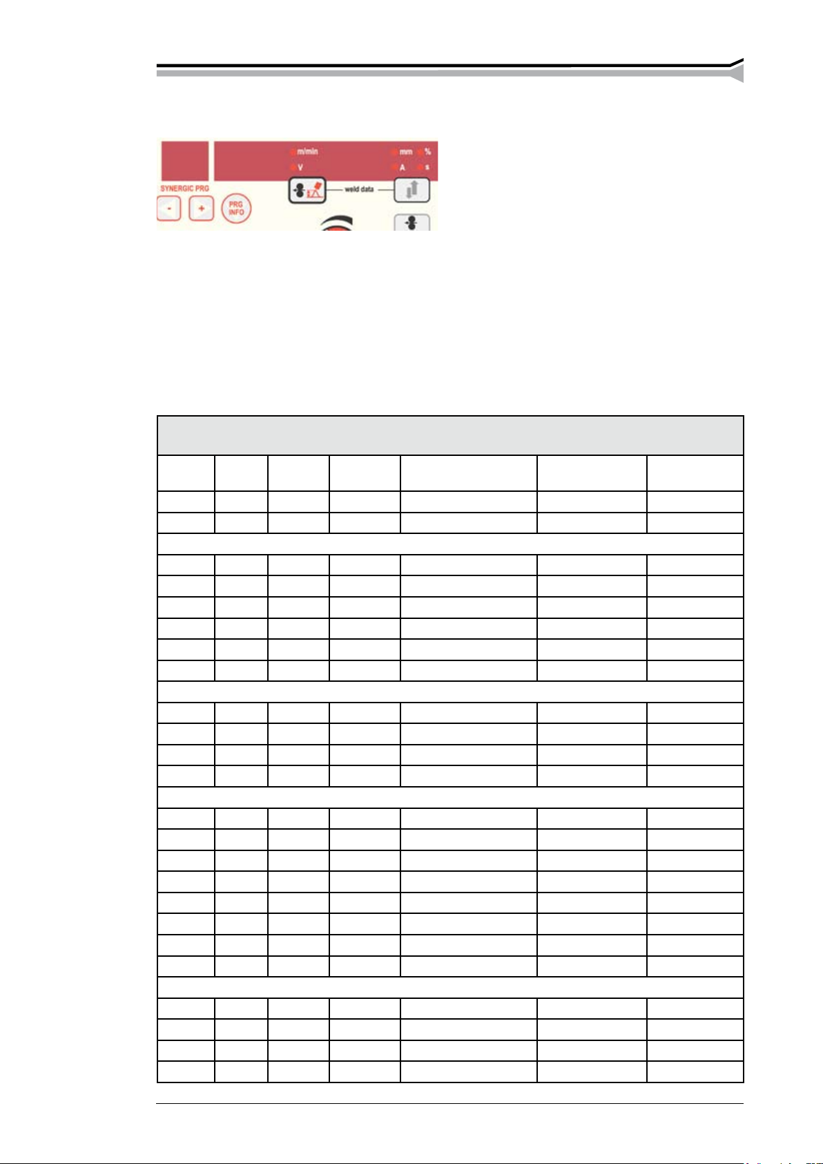
3.3.3. Selecting 1-mig/pulse mig synergy curves
The program number of the synergy curve is selected using the plus-minus buttons and is displayed
on "SYNERGIC PRG".
The middle display is actual material group display (eg. SS, AL, CUS, FE, GEN). Wire diameter
(mm) can be seen on the right side. This information will only be displayed for a while.
The “PRG INFO” button gives more curve information:
One press will revert to the material group and diameter display, a second will display the type
number of the material and a third run through the gas consistency components one by one.
KEMPACT PULSE 3000 Synergic programs
1-MIG Pulse Double
Pulse
00 All All All 1,0 - 18,0
01 All All All 0,5 - 18,0
SS-group
S1 S1 S1
S2 S2 S2
S3 S3 S3
S4 S4 S4
S5
S7
Al-group
A1 A1 A1 1,0 mm AlMg5 / AlMg4,5Mn Ar
A2 A2 A2 1,2 mm AlMg5 / AlMg4,5Mn Ar
A6 A6 A6 1,0 mm AlSi5 / AlSi12 Ar
A7 A7 A7 1,2 mm AlSi5 / AlSi12 Ar
Cu-group
C1 C1 C1 0,8 mm CuSi3 Ar
C2 C2 C2 0,9 mm CuSi3 Ar
C3 C3 C3 1,0 mm CuSi3 Ar
C4 C4 C4 1,2 mm CuSi3 Ar
C5 C5 C5 0,8 mm CuAl8 Ar
C6 C6 C6 0,9 mm CuAl8 Ar
C7 C7 C7 1,0 mm CuAl8 Ar
C8 C8 C8 1,2 mm CuAl8 Ar
Fe-group
F1 F1 F1 0,8 mm Fe Ar + 18 % CO
F2 F2 F2 0,9 mm Fe Ar + 18 % CO
F3 F3 F3 1,0 mm Fe Ar + 18 % CO
F4 F4 F4 1,2 mm Fe Ar + 18 % CO
Wire, ø Material Gas Wire Feed
Range
0,8 mm SS 308 / 316 Ar + 2 % CO
0,9 mm SS 308 / 316 Ar + 2 % CO
1,0 mm SS 308 / 316 Ar + 2 % CO
1,2 mm SS 308 / 316 Ar + 2 % CO
0,9 mm SS 316 FC Ar + 18 % CO
1,2 mm SS 316 FC Ar + 18 % CO
²
²
²
²
²
²
²
²
²
²
Kempact pulse 3000, Kempactcool 10 / 0813 – 13© Kemppi oy
Page 14

1-MIG Pulse Double
Pulse
F5 0,8 mm Fe CO
F6 0,9 mm Fe CO
F7 1,0 mm Fe CO
F8 1,2 mm Fe CO
FA FA FA 1,0 mm FeMC Ar + 18 % CO
FB FB FB
FD 1,2 mm FeFC Ar + 18 % CO
Wire, ø Material Gas Wire Feed
Range
²
²
²
²
²
1,2 mm FeMC Ar + 18 % CO
²
²
Auto
20 20 1,0 mm CuSi3-A Ar 1,1 – 2,0
1 21 21 1,0 mm CuSi3-A Ar 2,0 – 2,6
2 22 22 1,0 mm CuSi3-A Ar 2,4 – 3,1
3 23 23 1,0 mm CuSi3-A Ar 3,0 – 3,6
4 24 24 1,0 mm CuSi3-A Ar 3,5 – 4,1
5 25 25 1,0 mm CuSi3-A Ar 4,0 – 4,6
6 26 26 1,0 mm CuSi3-A Ar 4,5 – 5,1
7 27 27 1,0 mm CuSi3-A Ar 5,0 – 5,5
8 28 28 1,0 mm CuSi3-A Ar 5,5 – 6,0
9 29 29 1,0 mm CuSi3-A Ar 6,0 – 6,5
10 30 30 1,0 mm CuSi3-A Ar 6,4 – 7,0
11 31 31 1,0 mm CuSi3-A Ar 6,9 – 7,6
12 32 32 1,0 mm CuSi3-A Ar 7,4 – 8,1
14 – Kempact pulse 3000, Kempactcool 10 / 0813 © Kemppi oy
Page 15

3.3.4. Adjustments, display and weld data
Display for welding current and welding material
thickness. Changing can be made using the button
behind the display. There is a percentage display
(eg. gas consistency) and seconds display (see
timer). The relative length of arc will be displayed
when adjusted. Otherwise the predicted current
value is displayed (not in 2-MIG).
Process Manager™ for setting all welding
parameters.
The display for wire feed speed, welding voltage or material group. This can be switched using
the button under the display (wire feed speed/length of arc). The voltage can be adjusted in the
normal and 1-MIG position (wire feed range/the length of arc). During pulse welding the voltage
is determined by the wire feed speed while the length of arc affects some other parameters.
When pressed simultaneously, the weld data buttons recall the wire feed speed on the display, the
welding voltage and welding current values which have been used when welding was stopped.
3.3.5. Timer
intermittent welding
spot welding
The spot time is set immediately after pressing the switch button, on the display SPt.
The pause time is set accordingly, on the PSE display. The time is set using the Process
Manager.
3.3.6. Adjustment of welding dynamics
For adjusting of MIG/MAG welding dynamics, the adjustment value dyn -9...0...9 is
displayed. The welding stability and quantity of spatter are affected by the welding
dynamics control, the 0-position is the recommended reference range. Values -9...-1
give a smoother arc and less spatter, while values 1...9 give a rougher arc and increased
stability, when using a 100% CO² shielding gas when welding steel.
3.3.7. Remote control
Gun control, wire feed speed or welding power control is changed using RMT 10.
Control of the welding voltage or the length of the welding arc can be adjusted using
the potentiometer on the panel. Panel control, adjustments using the potentiometer on
the panel.
3.3.8. Mig extra functions
Crater lling, 1-MIG and pulse MIG:
Crater lling reduces welding mistakes caused by end craters. By pressing the 4T-trigger
continuously at the end of weld, a descending welding power is achieved which lls end
craters in a controlled manner. The descending time is kept constant using the 2T function,
and the welding power and end level can be changed using the SETUP-function.
Kempact pulse 3000, Kempactcool 10 / 0813 – 15© Kemppi oy
Page 16

Hot Start
Wire range/power/
Welding current
Start switch 4T
Crater lling
The Hot Start:
The Hot Start function is used with 1-MIG and pulse MIG welding. The Hot Start time by 4T Hot
Start time is determined by trigger function (see picture) and while by 2T function it is determined
by the SETUP parameters. The level of Hot Start can be changed by SETUP function.
The Hot Start level, Hot Start time by 2T, crater ll level and downslope time can be easily adjusted
using the ‘QUICK SETUP’ function:
1. Select the gun trigger function: 4T or 2T.
2. First, press the SETUP button and then , while still pressing the SETUP button, press the
extra function button.
3. Adjust the Hot Start level.
4. Repeat step 2, upon which the display will show the next adjustable parameter, depending
on the switch mode.
Exit by pressing any button (except SETUP)
3.3.9. Use of gas test
If you press the gas test button, gas will begin to ow without any starting power source
or wire feed. Gas ow can be measured by using an external measuring device.
Cut off the gas ow by pressing the same button again, or the gun trigger. If the trigger
is not pressed again, the gas ow will end within 20 seconds.
The display will show “GAS” and the time.
3.3.10. Testing wire feed
The wire feed switch will start the wire feed motor without opening the gas valve. The
power source will start up, but without providing welding power. The wire feed range
will be 5m/min but can be adjusted as desired.
16 – Kempact pulse 3000, Kempactcool 10 / 0813 © Kemppi oy
Page 17

3.3.11. Memory channels, MEMORY
The pulse panel has 100 channels for different welding options. Memory channels can be chosen
on the lower part of the panel using the memory block. Both welding values and functions can be
saved. Do the following:
1. Press twice if needed and and the SET light will start blinking if the channel is not
in use, while the light will stay on if the channel is in use.
2. Select the memory channel you want by pressing CH button
3. Make settings and save by pressing SAVE button.
4. Press twice. ON light turns on.
5. Start welding and set the values.
To change the values, the light must be switched from the ON to SET and then you can choose the
parameters, pressing the SAVE button afterwards. It is also possible to save the used parameters by
pressing SET when memory function is OFF (no lights). The channel can be emptied by pressing
and SET button in SET simultaneously.
Using saved settings
1. Press button.
2. Select the memory channel by pressing the CH button.
3. Start welding.
Memory channels in control device
Select memory channels by pressing the CH REMOTE button simultaneously and the gun control
light will start to blink. Use the saved values through the gun’s remote control.
You can use ve channels.
3.3.12. SETUP
Using the SETUP function, the user can change welding parameters which do not have their own
panel functions. These parameters can be set separately for 1-MIG and Pulse MIG. SETUP settings
are separate for each memory channel.
Kempact pulse 3000, Kempactcool 10 / 0813 – 17© Kemppi oy
Page 18

Setup functions on pulse panel
Parameter Name Nr Display 1-MIG Pulsed
MIG
PostGasTime 1 PoG X X Curve s PostGas time 0.0…9.9 s
PreGasTime 2 PrG X X Curve s PreGas time, functions by
HotStartLevel 11 Hot X X 30 % Hot start ratio to welding
HotStartTime 2T 12 H2t X X 2 s 2T Hot start timer 0.1-9.9 s
CraterFillLevel 14 CFL X X 30 % Welding end level 10-90 %
CraterFillSlope 15 CFS X X 1 s/10m Wire slowing-down
CreepStartLevel 17 CSL X X Syn Wire speed start value
CreepStartSlope 18 CSS X X 0 s/10m Wire speed up time
DoubleFrequency 21 dFr X Curve Hz Double pulse frequency
DoubleAmpiltude 22 dA X Curve m/min Double pulse power
StartPower 31 StP X X 0 Start power control
PulseCurrent 33 PuC X 0 % Pulse top current control
ArcLength
AdjRange
Calibration 42 CAL X X 1 V/100A Setting mid value of arc
WFS
Gun 53 Gun On liquidcooled thermal
GunRemote 54 GrE On Disabling of gun remote
Display reset
time
PRG INFO - feeld
selection
Restore 99 FAC X OFF Restoring factory settings
41 ALr X X 0 % Arc length adjustment
51 FS 18 m/min Wire feed maximum
81 dLY X X 5 s 1...20 s
82 diS X X 1 1,2,3
Factory
value
Unit Explanation
2T 0.0…9.9 s
power 50…+75%
1…20 s/10m
10…90
0.1…5 s/10m
control 0.4…8.0 Hz
variation
control 0.1…3.0 m/min
-9…0…+9
10…+15%
range 50…+75%
length ne adjustment
0.0…10.0 V/100A
18 or 25 m/min
protection on/off
control automatic
identication
(OFF=no reset,
Pan=panel and setup
ALL= also memory
channels)
18 – Kempact pulse 3000, Kempactcool 10 / 0813 © Kemppi oy
Page 19

Changing parameters
By pressing the 2T/4T (SETUP) selection switch a little longer the machine will enter the SETUP
state. The display will show the set parameter’s runnning number (blinking), its abbreviation and
value. Select the parameter number using the “SYNERGIC PRG” + and - buttons or the “SETUP”
button (which will jump by tens). Change the value using the control button (in some cases, the
value can be found from the synergy curve). “Syn” and the curve value will blink by turns on the
right of the display. Set the value by turning the button anticlockwise.
Exit for SETUP using a long press.
Frequency and amplitude of double pulse can be set in the separate ‘SET’ mode, obtained by rst
pressing the 2T/4T (SETUP) and, without releasing it, the method button. “dFr” and the frequency
in Hz will be displayed. “Syn” will appear if the frequency is based on synergy curves. Change this
value by turning the control button anticlockwise. Press it twice to display “dA” i.e. the amplitude
(m/min). Adjust this accordingly and exit SETUP by pressing any button other than SETUP.
3.3.13. Error codes
Error codes are among others the following:
Err 3: Overvoltages in the mains supply. Also the pilot light of overvoltage is lighting.
Err 4: The thermal protection of power suorce has stopped welding. Also the pilot light of
thermal protection is lighting.
Err 5: The cooling device has stopped welding.
Err 6: The terminal voltage has rised. Take the device to service.
Err 153: Liquid cooled PMT- or WS-gun is overheated. Or torch-PTC or RMT10 has beeb installed,
but the jumber inside the torch is in FU-position, look also instruction of torch.
Err 154: Overloading of the wire feed motor
Error code is eliminated when the reason is aborted, except Err 6, which demands to turn down
the machine.
3.4. COOLING UNIT OPERATION (KEMPACTCOOL 10)
The operation of cooling units KempactCool 10 is
controlled by the power source. The cooling unit pump
starts automatically when welding starts. Proceed as
follows:
1. Start power source.
2. Check water level and input ow of the reservoir, add
liquid if needed.
3. If you use a water-cooled gun you can ll it with
cooling liquid by pressing TEST-button (on cooling
unit).
The pump operates for 5 another minutes after welding has
been nished to cool the liquid to the same temperature
as in the machine surrounds. This reduces the need of
service.
Thermal overload
The thermal overload light is lit, the machine stops and display shows Err 5 when temperature
control of the machine has detected cooling water overheating. The cooling unit fan cools down
the water, and when the light goes out welding can be started again.
Water ow signal
Display shows Err 5 when water ow is blocked.
Kempact pulse 3000, Kempactcool 10 / 0813 – 19© Kemppi oy
Page 20

4. MAINTENANCE
4.1. DAILY MAINTENANCE
Be careful of mains voltage when handling electric cables!
Clean the wire channel of the gun and check the contact tip regularly. Always check the condition
of the mains and welding cable before operation and replace defective cables.
Note! Only a qualied electrician should remove or install the mains cable!
4.2. REGULAR MAINTENANCE
KEMPPI -service workshops sign special service contracts with customers for regular maintenance.
All parts are cleaned, checked and if necessary, repaired. The operation of the welding machine
is also tested.
4.3. DISPOSAL OF THE MACHINE
Do not dispose of electrical equipment together with normal waste!
In observance of European Directive 2002/96/EC on Waste Electrical and Electronic
Equipment and its implementation in accordance with national law, electrical equipment
that has reached the end of its life must be collected separately and returned to an
environmentally compatible recycling facility. As the owner of the equipment, you should
get information on approved collection systems from our local representative.
By applying this European Directive you will improve the environment and human
health!
5. ORDERING INFORMATION
Item Ordering number
Kempact Pulse 3000 621830002
KempactCool 10 621860001
GH 30 Gun holder 6256030
PMT 25 3 m 6252513
PMT 25 4,5 m 6252514
PMT 27 3 m 6252713
PMT 27 4,5 m 6252714
PMT 32 3 m 6253213
PMT 32 4,5 m 6253214
PMT 30W 6253043
PMT 30W 6253044
PMT 35 3 m 6253513
PMT 35 4,5 m 6253514
WS 35 6 m Al1,2 6253516A12
WS 35 6 m Ss1,0 6253516S10
WS 30W 6 m Al 1,2 6254206A12
WS 30W 6 m Ss 1,0 6254206S10
20 – Kempact pulse 3000, Kempactcool 10 / 0813 © Kemppi oy
Page 21

MMT 25 3 m 6252513MMT
MMT 25 4,5 m 6252514MMT
MMT 27 3 m 6252713MMT
MMT 27 4,5 m 6252714MMT
MMT 30W 3 m 6253043MMT
MMT 30W 4,5 m 6253044MMT
Remote Control Unit RMT 10 6185475
Earth cable 35 mm² 5 m 6184311
Transport unit ST 7 6185290 (for power source and gas bottle)
Transport unit P20 6185261 (power source, cooling unit and gas bottle)
Transport unit P250 6185268 (power source)
Lift hook 4298180
Gas hose 6 m W000566
Wire spool pole 4289880
5 kg spool adapter 4251270
DuraTorque™ 400 metal feed rolls
Parts of the DT400 metal feed rolls
W000731
W000732
W000711
W000718
W000891
9420507 washer 10.5x30x2.5 2 pcs per unit
gear ring 1 driving 2 pcs per unit
gear ring 2 pressing 2 pcs per unit
drive ring V groove 1,2/1,2 optional 4 pcs per unit
drive ring V groove 1,0/1,0 optional 4 pcs per unit
drive ring V groove 1,0/1,2 4 pcs per unit
Recommended for aluminium welding with Pulse MIG.
Kempact pulse 3000, Kempactcool 10 / 0813 – 21© Kemppi oy
Page 22

6. TECHNICAL DATA
Kempact Pulse 3000
Mains connection 3~400V +/-15%, 50/60Hz
Connected load
40% ED 12 kVA 250A
60% ED 10 kVA 207A
100% ED 7,5 kVA 160A
Mains cable/fuse 4x1,5 mm² - 5 m/16A delayed
Load capacity
40% ED 250A /26,5V
60% ED 207A /24V
100% ED 160A /22V
Adjustment range 8 - 30V
Wire feed speed
Open circuit voltage 56 V
Power ratio 0,69 (250A / 26V)
Efciency 0,84 (250A / 26V)
Filler wires
Fe, Ss
Cored wire 0,9 ... 1,2 mm
Al 0,9 ... 1,2 mm
CuSi
Shielding gas CO², Ar, Ar & CO² mixed gases
Wire spool diameter
Feed roll Ø 32 mm
Thermal class H (180 °C) / B (130 °C)
Dimensions
length 580 mm
width 280 mm
height 440 mm
Weight
Gun connector EURO
Principle of operation 4-wheel feed
1 - 18 m/min
0,6 ... 1,2 mm
0.8 ... 1,2 mm
300 mm (15 kg)
22 kg
Cooling unit KempactCool 10
Connection voltage 400 V - 15 % ... 10 %
Connection capacity 250 W
Cooling power 1 kW
Start pressure, max 4,5 bar
Cooling liquid 20 % - 40 % etanol/water
Reservoir volume n. 3 l
External dimensions length 580 mm
width 280 mm
height 300 mm
Weight
Kempact Pulse 3000 and Cooling unit KempactCool 10
Range of temperature for use - 20 °C ...+ 40 °C
Storage temperature for use - 40 °C ...+ 60 °C
Degree of protection IP23C
13 kg
The products meet conmormity reguirements for CE marking.
22 – Kempact pulse 3000, Kempactcool 10 / 0813 © Kemppi oy
Page 23

7. TERMS OF GUARANTEE
Kemppi Oy provides a guarantee for products manufactured and sold by them if defects in
manufacture and materials occur. Guarantee repairs must be carried out only by an Authorised
Kemppi Service Agent. Packing, freight and insurance costs to be paid by orderer. The guarantee is
effected on the date of purchase. Verbal promises which do not comply with the terms of guarantee
are not binding on guarantor.
Limitations on guarantee
The following conditions are not covered under the terms of guarantee: defects due to natural wear
and tear, non-compliance with operating and maintenance instructions, connection to incorrect or
faulty supply voltage (including voltage surges outside equipment spec.), incorrect gas pressure,
overloading, transport or storage damage, re of damage due to natural causes i.e. lightning or
ooding.
This guarantee does not cover direct or indirect travelling costs, daily allowances or accommodation.
Note: Under the terms of guarantee, welding torches and their consumables, feeder drive rolls and
feeder guide tubes are not covered. Direct or indirect damage due to a defective product is not
covered under the guarantee. The guarantee is void if changes are made to the product without
approval of the manufacturer, or if repairs are carried out using non-approved spare parts.
The guarantee is also void if repairs are carried out by non-authorised agents.
Undertaking guarantee repairs
Guarantee defects must be informed to Kemppi or authorised Kemppi Service Agents within the
guarantee period. Before any guarantee work is undertaken, the customer must provide proof of
guarantee or proof of purchase, and serial number of the equipment in order to validate the guarantee.
The parts replaced under the terns of guarantee remain the property of Kemppi.
Following the guarantee repair, the guarantee of the machine or equipment, repaired or replaced,
will be continued to the end of the original guarantee period.
Kempact pulse 3000, Kempactcool 10 / 0813 – 23© Kemppi oy
 Loading...