

Page 1

Operation instructions english
Gebrauchsanweisung deutsch
Gebruiksaanwijzing nederlands
Manuel dutilisation français
1922420E
Page 2

CONTENTS
1. PREFACE........................................................................................................................3
1.1. Introduction .......................................................................................................................3
1.2. Product introduction..........................................................................................................3
1.3. Operation safety................................................................................................................4
2. INSTALLATION...............................................................................................................5
2.1. Operation control and connectors.....................................................................................5
2.1.1. Feed 420R wire feeding control unit................................................................5
2.1.2. Feed 120R wire feeder ....................................................................................6
2.2. Units, accessories, cables.................................................................................................7
2.3. Parts of wire feed mechanism...........................................................................................8
2.4. Assembly of MIG system ..................................................................................................9
2.5. Installation.......................................................................................................................10
2.5.1. Wire feed mechanism (Feed 120R)......................................................................10
2.6. Mounting of MIG welding gun .........................................................................................10
2.7. Mounting and locking of wire reel (accessory)................................................................10
2.8. Automatic wire feed to gun (Feed 120R) ........................................................................ 11
2.9. Adjustment of pressure...................................................................................................11
2.10. Adjustment of tightness of wire reel brake (accessory)................................................... 11
2.11. Ground cable...................................................................................................................12
2.12. Shield gas .......................................................................................................................12
2.12.1. Installing gas bottle........................................................................................12
3. FEED 420R FUNCTIONS.............................................................................................. 13
3.1. Function panel.................................................................................................................13
3.2. Selection of welding process...........................................................................................13
3.3. Basic adjustments, basic displays...................................................................................13
3.4. MIG welding dynamics adjustment .................................................................................14
3.5. Selecting switch of main controls....................................................................................14
3.6. Display of selected 1-knob MIG synergetic program ......................................................14
3.7. 1-knob MIG synergy panel..............................................................................................14
3.8. Burn back time adjustment..............................................................................................14
3.9. Selection of 1-knob MIG synergetic curve ......................................................................15
3.10. Wire inch switch..............................................................................................................16
3.11. Gas purge switch ............................................................................................................16
3.12. Feed 420R error codes...................................................................................................16
4. ACCESSORIES............................................................................................................. 16
4.1. Synchronizing unit Sync 400...........................................................................................16
4.2. Gas guard GG 400..........................................................................................................16
4.3. Hanging onto boom.........................................................................................................16
5. SERVICE AND OPERATION DISTURBANCES...........................................................17
6. ORDERING NUMBERS ................................................................................................18
7. TECHNICAL DATA........................................................................................................19
2 – Kempomig Feed 420R, 120R / 0429
© COPYRIGHT KEMPPI OY
Page 3

1. PREFACE
1.1. INTRODUCTION
Congratulations on having purchased this product. Properly installed Kemppi products should
prove to be productive machines requiring maintenance at only regular intervals. This manual is
arranged to give you a good understanding of the equipment and its safe operation. It also
contains maintenance information and technical specifi cations. Read this manual from front
to back before installing, operating or maintaining the equipment for the fi rst time. For further
information on Kemppi products please contact us or your nearest Kemppi distributor.
Specifi cations and designs presented in this manual are subject to change without prior notice.
In this document, for danger to life or injury the following symbol is used:
Read the warning texts carefully and follow the instructions. Please also study the Operation
safety instructions and respect them when installing, operating and servicing the machine.
1.2 PRODUCT INTRODUCTION
Kempomig Feed 420R together with Feed 120R is a welding system designed for robotic
and automated welding. It consists of Feed 420R with inbuilt robot interface and a robot arm
mounted feed unit Feed 120R. These two units are connected with an intermediate cable
assembly.
Manual control is possible by using an interchangeable control panel with basic controls and
displays for MIG welding and synergetic MIG.
Welding operation is controlled by microprocessor. The wire feed motor includes an amplifi ed
tachometer feedback system to ensure accurate wire feed speed.
The interface stage handles all major I/O signals for automated requirements.
© COPYRIGHT KEMPPI OY
Kempomig Feed 420R, 120R / 0429 – 3
Page 4

1.3. OPERATION SAFETY
Please study these Operation safety instructions and respect them when installing, operating and
servicing the machine.
Welding arc and spatters
Welding arc hurts unprotected eyes. Be careful also with refl ecting arc fl ash. Welding arc and
spatter burn unprotected skin. Use safety gloves and protective clothing.
Danger for fi re or explosion
Pay attention to fi re safety regulations. Remove fl ammable or explosive materials from
welding place. Always reserve suffi cient fi re-fi ghting equipment on welding place. Be prepared
for hazards in special welding jobs, e.g. for the danger of fi re or explosion when welding
container type work pieces. Note! Fire can break out from sparks even several hours after the
welding work has been fi nished!
Mains voltage
Never take welding machine inside a work piece (eg. container or truck). Do not place welding
machine on a wet surface. Always check cables before operating the machine. Change defect
cables without delay. Defect cables may cause an injury or set out a fi re. Connection cable must
not be compressed, it must not touch sharp edges or hot work pieces.
Welding power circuit
Isolate yourself by using proper protective clothing, do not wear wet clothing. Never work on a
wet surface or use defect cables. Do not put MIG gun or welding cables on welding machine or
on other electric equipment. Do not press MIG gun’s switch, if the gun is not directed towards a
work piece.
Welding fumes
Take care that there is suffi cient ventilation during welding. Take special safety precautions
when welding metals which contain lead, cadmium, zinc, mercury or beryllium.
4 – Kempomig Feed 420R, 120R / 0429
© COPYRIGHT KEMPPI OY
Page 5
2. INSTALLATION
2.1 OPERATION CONTROL AND CONNECTORS
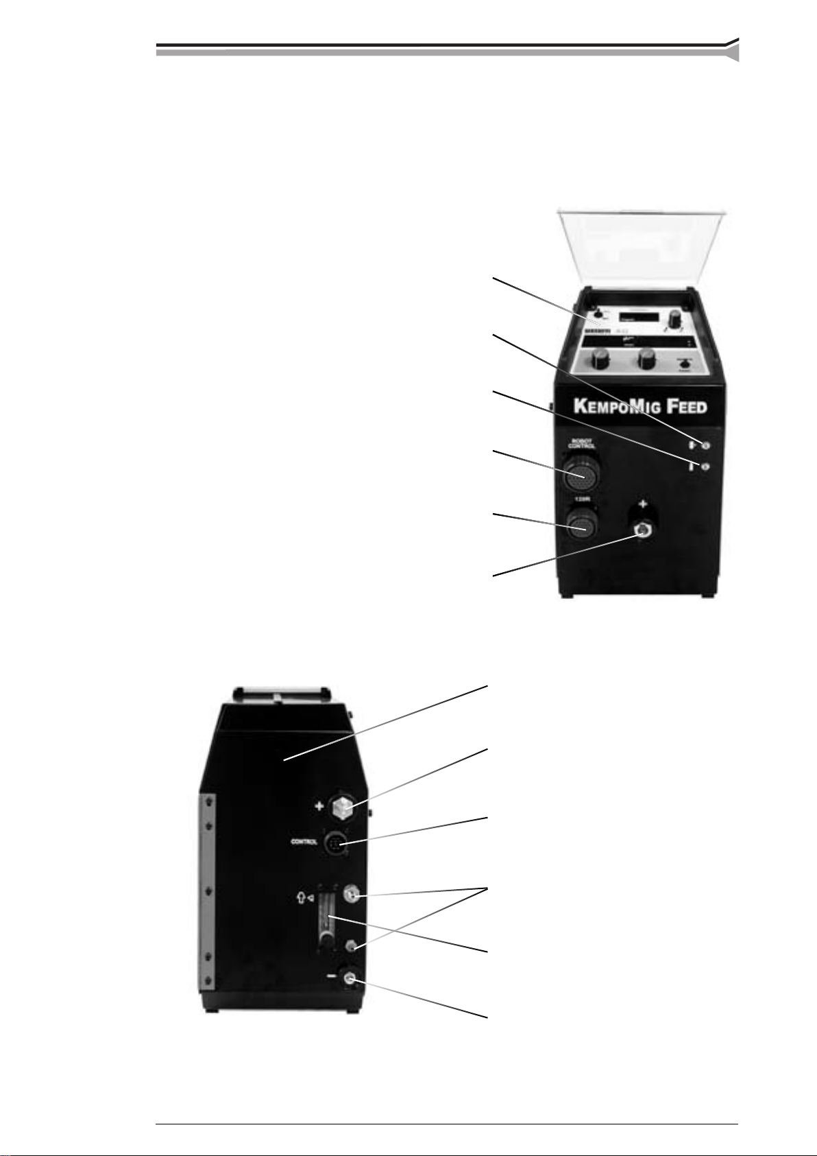
2.1.1. Feed 420R wire feeding control unit
Control panel
Wire inch
Gas purge
Robot controller
connector
Control cable connector to Feed 120R
Welding current output connector (+)
Hole for wire outlet connector
Fixed welding cable to power source
Control cable connector (Kempomig)
Gas snap connectors
© COPYRIGHT KEMPPI OY
Gas fl ow meter (accessory)
Voltage monitoring connector (–)
Kempomig Feed 420R, 120R / 0429 – 5
Page 6
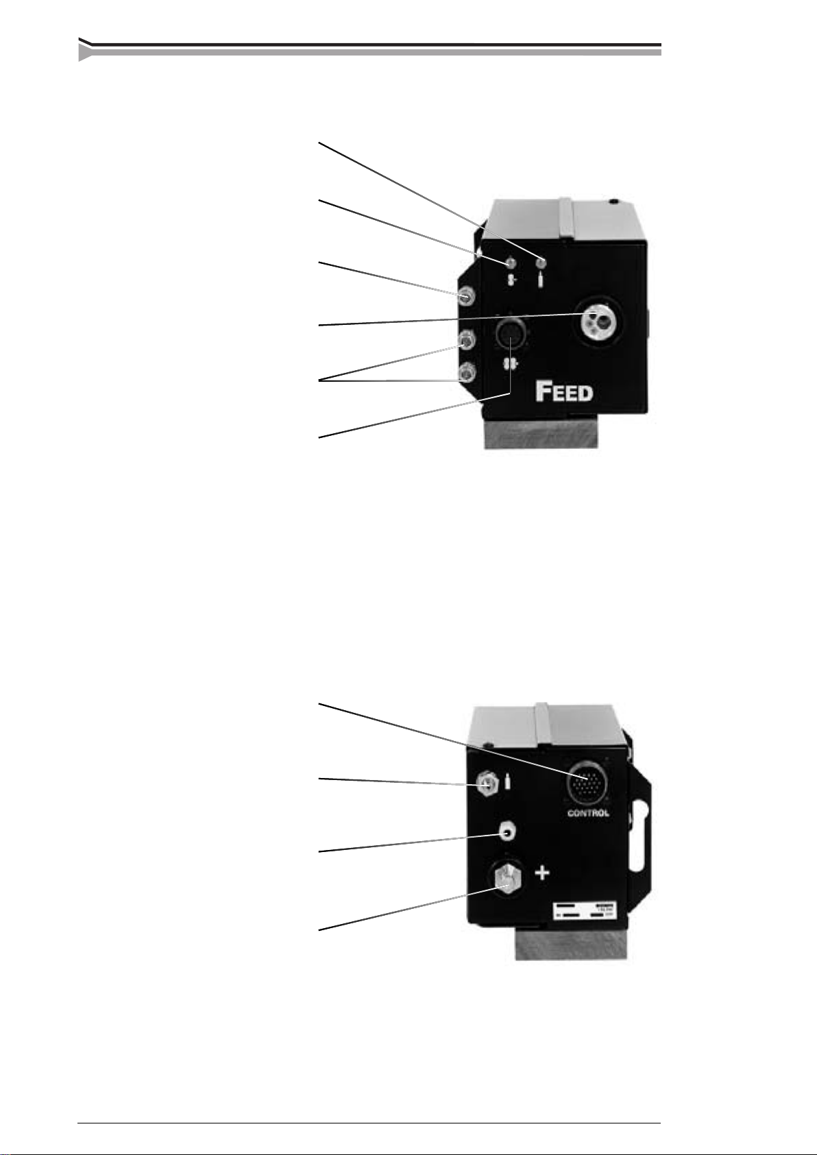
2.1.2. Feed 120R wire feeder
Gas purge
Wire inch
Snap connector for air blast
Euro connector for robot gun
Snap connectors for
cooling liquid
Connector for motorised gun
Control cable connector (Feed 420R)
Snap connector for gas
Wire liner inlet
Welding current cable connector
6 – Kempomig Feed 420R, 120R / 0429
© COPYRIGHT KEMPPI OY
Page 7

2.2. UNITS, ACCESSORIES, CABLES
SYNC400
GG400
Intermediate cable
(Kempomig-Feed)
Feed 420R
Branch cable
KEMPOMIG4000WR
MSD1
Intermediate cable
Feed 120R
© COPYRIGHT KEMPPI OY
Kempomig Feed 420R, 120R / 0429 – 7
Page 8

2.3 PARTS OF WIRE FEED MECHANISM
8 – Kempomig Feed 420R, 120R / 0429
© COPYRIGHT KEMPPI OY
Page 9

2.4. ASSEMBLY OF MIG EQUIPMENT
Kempomig power source:
Read paragraph INSTALLATION in the operation instructions (1922430E) for the Kempomigpower source in question.
Feed 420R and Feed 120R wire feeding equipment:
1. Mount the wire feeder onto the shaft which is on top of the power source. The shaft must have
plastic insulation / bear bushing.
2. Mount control cable of interconnection cable and welding current cable to connectors on the
rear wall of Feed 420R. Select the MIG gun´s polarity (+ or –) according to welding wire you
are using.
3. Mount the MIG gun to EURO connector on the front wall of the Feed 120R.
Use guide tubes and contact tips according to manufacturer´s operation instructions.
Accessories which are too tight or otherwise unsuitable for the wire type used will cause wire
feed disturbances.
4. If you mount the Feed 420R onto boom, see that the wire feeder unit´s chassis is without
galvanic contact to boom.
5. Max. wire feed speed
When the unit is delivered the max. wire feed speed is 18 m/min, which is enough for most
welding works. If you need a higher speed, you can increase the max. wire feed speed to
25 m/min by replacing the gear wheel on motor shaft to a bigger one as well as through change
of jumper on the control card. The big gear wheel (D40) belongs to delivery kit of the Feed
120R.
When necessary speed is changed according to following:
8
7
6
5
4
3
2
25 m/min 18 m/min
1
JUMPER BLOCK
A001
– Open side plate and move JUMPER BLOCK´s fi rst coding piece on control card A001 to
point 25m/min.
– Open tightening lever (20). Remove lower feed rolls (21). Release screw (23) and its washer.
Remove gear wheel D28 (24) from motor shaft.
20 25
21 23 24 21 22 25 22
– Loosen screws (25) (3 pc) 1 twist. Mount the D40 gear wheel onto motor shaft. Screw the
screw (23) with its washer back.
– Put feed rolls (21) back to their axles, however don´t fasten yet fastening screws of the feed
rolls (22).
– Lift the motor so that the tooth gap between gear wheel and both lower feed rolls is approx.
0,2 mm.
© COPYRIGHT KEMPPI OY
Kempomig Feed 420R, 120R / 0429 – 9
Page 10

– Tighten screws (25). Check gear teeth gaps, when necessary put the motor into a better
position. Screw on the mounting screws of feed rolls (22).
Too small a gap between gear wheel and feed rolls will overload motor.
Too big a gap for its part might cause too rapid wearing for teeth of feed rolls
and gear wheel.
– Mounting of push-pull gun´s synchronizing unit SYNC 400 and gas guard GG is described in
the mounting instructions delivered with the units.
2.5. INSTALLATION
2.5.1. Wire feed mechanism (Feed 120R)
Wire feed rolls are available with plain groove, knurled groove and with U groove for different
purposes.
Feed rolls with plain groove: Universal feed roll for welding of all kinds of wires
Feed rolls with knurled groove: Special feed roll for cored wires and steel wires
Feed rolls with U groove: Special feed roll for aluminium wires
Wire feed rolls have two grooves for different fi ller wire diameters. Correct wire groove is
selected by moving selecting washer (28) from one side to another in feed roll.
Feed rolls and wire guide tubes have colour codes in order to make identifi cation easier (see table
on page 8).
feed rolls
colour fi ller wire ø mm (inch)
white 0.6 and 0.8 (0.030)
red 0.9/1.0 and 1.2 (0.035, 0.045 and 0.052)
yellow 1.4, 1.6 and 2.0 (1/16 and 5/64)
black 2.4 (3/32)
guide tubes
colour fi ller wire ø mm (inch)
orange 0.6-1.6 (0.024-1/16)
blue over 1.6 (over 1/16)
In delivery Feed 120R is equipped with red feed rolls with plain groove and with orange wire
guide tubes for welding fi ller wires of 0.9-1.2 mm (0.035”, 0.045” ja 0.052”).
2.6. MOUNTING OF MIG WELDING GUN
In order to ensure trouble-free welding, check the operation instructions of gun used that wire
guide tube and contact tip of gun are according to manufacturer´s recommendation, and suitable
for wire diameter and type in question. Too tight a wire guide tube might cause for wire feeder
unit a bigger stress than normally as well as disturbances in wire feed.
Screw snap connector of gun tight to avoid any voltage losses on connecting
surface.
A loose connection will heat gun and wire feeder unit.
2.7. MOUNTING AND LOCKING OF WIRE REEL (ACCESSORY)
LOCKED OPEN
10 – Kempomig Feed 420R, 120R / 0429
© COPYRIGHT KEMPPI OY
Page 11

– Release locking nails of wire reel hub by turning locking knob a quarter of a round.
– Mount the reel at its place. Note rotating direction of reel!
– Lock the reel with locking knob, locking nails of hub remain in outside position and will
lock the reel.
Check the fi ller wire reel that there are no parts sticking out which could e.g. chafe
against chassis or door of wire feeder unit. Dragging parts might expose chassis of
wire feeder unit under voltage.
2.8. AUTOMATIC WIRE FEED TO GUN (FEED 120R)
Automatic wire feed makes change of wire reel more rapid. In reel change the pressure of feed
rolls need not be released and fi ller wire goes automatically to correct wire line.
– Make sure that groove of feed roll matches the diameter of welding wire used. Feed roll
groove is selected by moving the groove selecting washer (28).
28
28
– Release the wire end from reel and cut off the bent length. Be careful that the wire does not
spill from the reel to sides!
– Straighten the wire at a length of about 20 cm and see that its end has no sharp edges (fi le off
if necessary). A sharp edge may damage the wire guide tube and contact tip of the welding
gun.
– Draw a bit of loose wire from wire reel. Feed wire through back liner to feed rolls. Do not
release pressure of feed rolls!
– Press the gun switch and feed a bit wire until wire goes through feed rolls to gun. See that
wire is in grooves of both feed roll pairs!
– Press still the gun switch until wire has come through contact tip.
Automatic feed may sometimes fail with thin wires (Fe, Ss: 0,6...0,8 mm, Al, Fc: 0,8...1,0 mm).
In case open feed rolls and feed wire manually.
2.9. ADJUSTMENT OF PRESSURE
Adjust the pressure of feed rolls with the control screw (20) so that the wire is fed into the wire
guide tube evenly and allows a little braking when coming out from the contact tip without
slipping at the feed rolls.
Excessive pressure causes fl attening of the fi ller wire and damage to the coating.
It also causes undue wear of the feed rolls as well as friction.
2.10. ADJUSTMENT OF TIGHTNESS OF WIRE REEL BRAKE
(ACCESSORY)
41
© COPYRIGHT KEMPPI OY
Kempomig Feed 420R, 120R / 0429 – 11
Page 12

Brake force is adjusted through hole in locking device of reel hub by screwing the control screw
(41) with screwdriver.
Adjust brake force so high that the wire does not become too loose on the reel so that it would
spill from the reel when the rotation of the reel stops. Need for brake force is increased with
increase of the wire feed speed.
Since the brake loads the motor for its part, you should not keep it unnecessarily tight.
2.11. GROUND CABLE
Fasten earthing clamp of ground cable carefully, preferably direct to welding piece. Contact
surface of clamp should always be as large as possible.
Clean the fastening surface from paint and rust!
Use 50 mm
2
cables in your MIG equipment. Thinner cross-sectional areas might
cause overheating of connectors and insulations.
Make sure that the welding gun in your use is designed for max. welding current
needed!
Never use a damaged welding gun!
2.12. SHIELD GAS
Handle gas bottle with care. There is a risk for injury if gas bottle or bottle valve
is damaged!
For welding stainless steels, mixed gases are normally used. Check that the gas bottle valve
is suitable for the gas. The fl ow rate is set according to the welding power used in the job. A
suitable fl ow rate is normally 8 - 10 l/min. If the gas fl ow is not suitable, the welded joint will be
sporous. Contact your local Kemppi dealer for choosing gas and equipment.
2.12.1. Installing gas bottle
Always fasten gas bottle properly in vertical position in a special holder on the
wall or on a carriage. Remember to close gas bottle valve after having fi nished
welding.
Parts of gas fl ow regulator
A
C
F
A Gas bottle valve
B Press regulation screw
G
C Connecting nut
12 – Kempomig Feed 420R, 120R / 0429
D Hose spindle
B
E Jacket nut
F Gas bottle pressure meter
E
G Gas hose pressure meter
D
© COPYRIGHT KEMPPI OY
Page 13

The following installing instructions are valid for most gas fl ow regulator types:
1. Step aside and open the bottle valve (A) for a while to blow out possible impurities from
the bottle valve.
2. Turn the press regulation screw (B) of the regulator until no spring pressure can be felt.
3. Close needle valve, if there is one in the regulator.
4. Install the regulator on bottle valve and tighten connecting nut (C) with a wrench.
5. Install hose spindle (D) and jacket nut (E) into gas hose and tighten with hose clamp.
6. Connect the hose with the regulator and the other end with the wire feed unit.
Tighten the jacket nut.
7. Open bottle valve slowly. Gas bottle pressure meter (F) shows the bottle pressure.
Note! Do not use the whole contents of the bottle. The bottle should be fi lled when the
bottle pressure is 2 bar.
8. Open needle valve if there is one in the regulator.
9. Turn regulation screw (B) until hose pressure meter (G) shows the required fl ow
(or pressure). When regulating fl ow amount, the power source should be in switched on and
the gun switch pressed simultaniously.
Close bottle valve after having fi nished welding. If the machine will be out of use for a long
time, unscrew the pressure regulation screw.
3. FEED 420R FUNCTIONS
3.1. FUNCTION PANEL
3.2. SELECTION OF WELDING PROCESS
Synergic MIG / MAG welding (1-knob MIG): MIG welding, where wire
feed speed defi nes values of other welding parameters enabling power level
adjustment of welding from one control knob. Dependence of welding
parameters from wire feed speed is defi ned by choice of synergic curve for
fi ller wire and gas being used.
MIG / MAG welding with independent wire feed and voltage controls.
3.3. BASIC ADJUSTMENTS, BASIC DISPLAYS
© COPYRIGHT KEMPPI OY
Kempomig Feed 420R, 120R / 0429 – 13
Page 14

(1) Wire feed speed adjustment by MIG / MAG. Welding power adjustment by synergic 1-knob
MIG.
(2) Welding voltage adjustment by MIG/MAG. Arc length adjustment by synergic 1-knob MIG.
(3) Wire feed speed in m/min, plate thickness display in mm. Note! you can select the plate
thickness display only by synergic 1-knob MIG.
With the selecting switch (4) is selected which variable is visible in the display. The plate
thickness display is an informative thickness display for welding plates when making horizontal
vertical fi llet welds.
(5) Set value display for welding voltage by MIG and 1-knob MIG, V.
This display is also used as display for MIG welding dynamics, -9...0...9.
3.4. MIG WELDING DYNAMICS ADJUSTMENT
With MIG welding dynamics adjustment, you can infl uence welding stability
and spatter amount. Zero setting is recommended basic setting. Values –>
min (-1...-9), softer arc for reduced spatter amount. Values –> max (1...9),
harder arc for increased stability and when 100 % CO
shielding gas is used
2
in welding of steel.
3.5. SELECTING SWITCH OF MAIN CONTROLS
Remote control, basic controls are made from robotic control unit.
Local control, basic controls are made from potentiometers of the panel.
3.6. DISPLAY OF SELECTED 1-KNOB MIG SYNERGETIC
PROGRAM
The display shows number for 1-knob MIG program which has been
selected with selecting switches on the synergy panel. If on display is visible
´– –´, you have not selected any 1-knob MIG program. Then welding is
prevented. By normal MIG / MAG welding the display is black.
3.7. 1-KNOB MIG SYNERGY PANEL
567
4
3
2
1
Material
choice switch
1
8
9
H
L
2
3
Wire diameter
choice switch
Selecting switch for
crater fi lling
Burn back time adjustment
1-MIG synergy panel is in the reel cabinet. On the MIG synergy panel there are selecting
switches for 1-knob MIG synergetic curve, selecting switch for 1-knob MIG crater fi lling as
well as potentiometer for burn back time adjustment.
3.8. BURN BACK TIME ADJUSTMENT
Burn back time is adjusted steplessly. The value for burn back time is selected according to
material in question so that the fi ller wire will not stick on the weld piece at the weld end, and
also that there will not become too big a ”ball” at the wire tip. The burn back time is changed
automatically as correct according to changes of the wire feed speed.
14 – Kempomig Feed 420R, 120R / 0429
© COPYRIGHT KEMPPI OY
Page 15

3.9. SELECTION OF 1-KNOB IG SYNERGETIC CURVE
Feed 420R includes preset programs for synergic 1-knob MIG welding of the most common
materials. The preset programs are presented in the enclosed table. On reel cabinet door of Feed
420R there is a guide sticker, which tells positions of selecting switches and program numbers.
Material Wire diameter Program
choice switch choice switch number ø Wire material Shielding gas
1 1 11 0.8 Fe 100% CO
1 2 12 1.0 Fe 100% CO
1 3 13 1.2 Fe 100% CO
2
2
2
2 1 21 0.8 Fe Ar15-25% CO
2 2 22 1.0 Fe Ar15-25% CO
2 3 23 1.2 Fe Ar15-25% CO
3 1 - - no program
3 2 - - no program
3 3 33 1.2 Metal cored wire Ar15-25% CO
4 1 - - no program
4 2 - - no program
4 3 43 1.2 Rutile fl ux cored wire Ar15-25% CO
5 1 51 0.8 Ss316 Ar25% CO2, 0
5 2 52 1.0 Ss316 Ar25% CO2, 0
5 3 53 1.2 Ss316 Ar25% CO2, 0
6 1 - - no program
6 2 62 1.0 AlMg5, AlMg4, 5Mn 100% Ar
6 3 63 1.2 AlMg5, AlMg4, 5Mn 100% Ar
7 1 - - no program
7 2 72 1.0 AlSi5 100% Ar
7 3 73 1.2 AlSi5 100% Ar
2
2
2
2
2
2
2
2
8 1 - - no program
8 2 - - no program
8 3 83 1.2 SsFCR Ar15-25% CO
9 1 91 0.8 CuSi3 100% Ar
9 2 92 1.0 CuSi3 100% Ar
9 3 - - no program
H 1 - - no program
H 2 H2 1.0 Ss309 Ar2% CO
, 0
2
H 3 H3 1.2 Ss309 Ar2% CO2, 0
L 1 L1 0.8 Fe Ar8%CO
L 2 L2 1.0 Fe Ar8%CO
L 3 L3 1.2 Fe Ar8%CO
2
2
2
2
2
2
© COPYRIGHT KEMPPI OY
Kempomig Feed 420R, 120R / 0429 – 15
Page 16

3.10. WIRE INCH SWITCH
The wire inch switch starts the wire feed motor without starting the power
source and without opening the gas valve.
3.11. GAS PURGE SWITCH
The gas purge switch opens the gas valve without starting the wire feed
motor and the power source.
3.12. FEED 420R ERROR CODES
By every start possible error states in equipment are checked. If an error state is found, the error
in question is shown with an E text appearing in the panel display.
Here are some error codes:
E.09: Overloading of wire feed motor, which can be e.g. due to blocked wire guide tube of
gun, or too sharply bent gun cable.
E.12: The welding is prevented because the shielding gas control of the gas guard GG 400
has released.
The error codes disappear by following start, if reason of the error code is eliminated.
4. ACCESSORIES
4.1. SYNCHRONIZING UNIT SYNC 400
By means of Sync 400 you can connect the push-pull gun to the Feed 420R wire feeding control
unit. Push-pull gun is most commonly used for feeding of aluminium wires. Push-pull gun
enables extending the working radius up to 10 m. Sync 400 is mounted into electronics case of
Feed 420R. Mounting of Sync 400 is described in the mounting instructions delivered with the
unit.
4.2. GAS GUARD GG 400
With gas guard accessory you can prevent weld defects due to lacking or wrong fl ow of
shielding gas. Functions of gas guard are as follows:
– Prevention of welding if the gas pressure is not suffi cent on the wire feeder unit.
– Stopping of welding if shielding gas pressure disappears during welding.
– When gas guard has prevented welding, error message E.12 appears on welding panel
displays.
– Shielding gas fl ow meter / regulator. Regulation range 5-25 l/min. Display is calibrated for
shielding gas Ar CO
(75 % Ar, 25 % CO2)
2
4.3. HANGING ONTO BOOM
The lift hook is mounted to handle of Feed 420R. The position depends on the lift hook hole
position.
16 – Kempomig Feed 420R, 120R / 0429
© COPYRIGHT KEMPPI OY
Page 17

5. SERVICE AND OPERATION DISTURBANCES
The amount of use and working environment should be taken into consideration when planning
the frequency of maintenance of Feed 420R and 120R. Careful use and preventive maintenance
will help to ensure trouble-free operation.
Following maintenance operations should be carried out at least every six months:
Check:
– Feed roll grooves. Excessive wear of grooves causes wire
feed problems.
– Wire guide tubes. Badly worn feed rolls and wire guide
tubes should be discarded.
– Wire guide tube in the gun should be set as close to the feed
rolls as possible and the wire must follow a straight line
from the end of the tube to the groove of the feed roll.
– Reel brake adjustment.
– Electrical connections:
* Oxidized couplings must be cleaned
* Loose couplings must be tightened
Clean dust and dirt from the equipment.
When using compressed air, always protect your eyes with proper eye protection.
In case of problems contact an authorised KEMPPI service workshop.
twice a year
© COPYRIGHT KEMPPI OY
Kempomig Feed 420R, 120R / 0429 – 17
Page 18

6. ORDERING NUMBERS
Wire feed units
Feed 420R wire feed control unit 6236420
Feed 120R wire feed unit 6236120
Accessories of Feed 420R
Sync 400 6263120
GG 400 6237405
Wire reel hub 4289880
Power sources
Kempomig 4000R 6227400R
Kempomig 4000WR 6227400WR
MSD 1 6185666
Cabels
Voltage monitor cable 4288700
Branch connector 9771637
Intermediate cable assembly 5 m 6260421
10 m 6260425
Earth cable 50 mm
50 mm
Earth cable 70 mm
70 mm
2
2
2
2
5 m 6184511
10 m 6184512
5 m 6184711
10 m 6184712
MIG guns for robotic and automated welding
MT38M 3,0 m 6253038
MT-51MW 1,5 m / SK 6255156
MT-51MW 1,5 m / K30 6255157
MT-51MW 3,0 m / SK 6255158
MT-51MW 3,0 m / K30 6255159
Interconnection cables
Interconnection cables Kempomig 4000R, 4000WR / Feed 420R
KW 50-1.3-GH 6260350
Multimig 70-11-GH 6260182
Return current cable
5 m - 50 mm
18 – Kempomig Feed 420R, 120R / 0429
2
6184511
© COPYRIGHT KEMPPI OY
Page 19

7. TECHNICAL DATA
Feed 420R, 120R Feed 120R
Working voltage (safety voltage) 30 VAC 50/60 Hz
Rated power 150 VA
Loading capacity 60 % ED 400 A
100 % ED 310 A
Operation principle 4 roll drive
Diameter of feed roll 32 mm
Wire feed speed I 0...18 m / min
II 0...25 m / min
Filler wires ø Fe, Ss 0,6...1,2 mm
ø Filler wire 0,8...1,6 mm
ø Al 1,0...1,6 mm
Wire reel max. weight 20 kg
max. size ø 300 mm
Gun connector Euro
Operation temperature range -20...+40 °C
Storage temperature range -40...+60 °C
Degree of protection IP 23C
Dimensions length 570 mm 319 mm
width 210 mm 152 mm
height 440 mm 167 mm
Weight 15 kg 8 kg
The product meets conformity requirements for CE-marking.
© COPYRIGHT KEMPPI OY
Kempomig Feed 420R, 120R / 0429 – 19
Page 20

KEMPPI OY
PL 13
FIN – 15801 LAHTI
FINLAND
Tel (03) 899 11
Telefax (03) 899 428
www.kemppi.com
KEMPPIKONEET OY
PL 13
FIN – 15801 LAHTI
FINLAND
Tel (03) 899 11
Telefax (03) 7348 398
e-mail: myynti.fi @kemppi.com
KEMPPI SVERIGE AB
Box 717
S – 194 27 UPPLANDS VÄSBY
SVERIGE
Tel (08) 59 078 300
Telefax (08) 59 082 394
e-mail: sales.se@kemppi.com
KEMPPI NORGE A/S
Postboks 2151, Postterminalen
N – 3103 TØNSBERG
NORGE
Tel 33 34 60 00
Telefax 33 34 60 10
e-mail: sales.no@kemppi.com
KEMPPI DANMARK A/S
Literbuen 11
DK – 2740 SKOVLUNDE
DANMARK
Tel 44 941 677
Telefax 44 941 536
e-mail:sales.dk@kemppi.com
KEMPPI BENELUX B.V.
Postbus 5603
NL – 4801 EA BREDA
NEDERLAND
Tel (076) 5717 750
Telefax (076) 5716 345
e-mail: sales.nl@kemppi.com
KEMPPI (UK) Ltd
Martti Kemppi Building
Fraser Road
Priory Business Park
BEDFORD, MK443WH
ENGLAND
Tel 0845 6444201
Fax 0845 6444202
e-mail: sales.uk@kemppi.com
KEMPPI FRANCE S.A.
S.A. au capital de 5 000 000 F.
65 Avenue de la Couronne des Prés
78681 EPONE CEDEX
FRANCE
Tel (01) 30 90 04 40
Telefax (01) 30 90 04 45
e-mail: sales.fr@kemppi.com
KEMPPI GmbH
Otto – Hahn – Straße 14
D – 35510 BUTZBACH
DEUTSCHLAND
Tel (06033) 88 020
Telefax (06033) 72 528
e-mail:sales.de@kemppi.com
KEMPPI SP. z o.o.
Ul. Piłsudskiego 2
05-091 ZA¸BKI
Poland
Tel +48 22 781 6162
Telefax +48 22 781 6505
e-mail: info.pl@kemppi.com
KEMPPI SWITZERLAND AG
Chemin de la Colice 4
CH-1023 Crissier/ Lausanne
SUISSE
Tel. +41 21 6373020
Telefax +41 21 6373025
e-mail: sales.ch@kemppi.com
KEMPPI WELDING
MACHINES AUSTRALIA PTY LTD
P.O. Box 404 (2/58 Lancaster Street)
Ingleburn NSW 2565, Australia
Tel. +61-2-9605 9500
Telefax +61-2-9605 5999
e-mail: info@kemppi.com.au
Ver. 7
www.kemppi.com
 Loading...