

Page 1
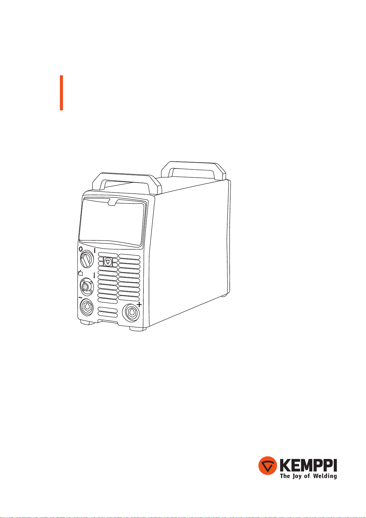
FastMig
M 320, 420, 520
Operating manual
Brugsanvisning
Gebrauchsanweisung
Manual de instrucciones
Käyttöohje
Manuel d’utilisation
Manuale d’uso
Gebruiksaanwijzing
Bruksanvisning
Instrukcja obsługi
Manual de utilização
EN
DA
DE
ES
FI
FR
IT
NL
NO
PL
PT
Инструкции по эксплуатации
Bruksanvisning
操作手册
RU
SV
ZH
Page 2

Page 3

OPERATING MANUAL
English
Page 4

EN
CONTENTS
1. Preface ........................................................................................................... 3
1.1 General ....................................................................................................................................... 3
1.2 Product introduction ............................................................................................................ 4
1.2.1 Operation control and connectors ................................................................................. 4
1.3 Accessories ................................................................................................................................ 4
1.3.1 Remote control devices ................................................................................................... 4
1.3.2 Cables ............................................................................................................................... 5
2. Installation .................................................................................................... 6
2.1 Positioning of the machine ................................................................................................ 6
2.2 Distribution network ............................................................................................................. 6
2.3 Connection to the mains supply ...................................................................................... 7
2.4 Welding and earth return cables ...................................................................................... 8
3. Operation controls .....................................................................................8
3.1 Main switch I/O ....................................................................................................................... 8
3.2 Pilot lamps ................................................................................................................................. 8
3.3 Operation of cooling fan ..................................................................................................... 8
4. Manual metal arc welding ........................................................................ 9
5. Maintenance ................................................................................................ 9
5.1 Daily maintenance ................................................................................................................. 9
5.2 Periodic maintenance ........................................................................................................... 9
5.3 Service Workshop maintenance .....................................................................................10
6. Operation disturbances .......................................................................... 10
7. Disposal of the machine ......................................................................... 11
8. Ordering numbers .................................................................................... 11
9. Technical data ............................................................................................ 12
2
FastMig M 320, 420, 520
Page 5

1. PREFACE
1.1 General
Congratulations on choosing the FastMig welding equipment. Used correctly, Kemppi
products can signicantly increase the productivity of your welding, and provide years of
economical service.
This operating manual contains important information on the use, maintenance and safety of
your Kemppi product. The technical specications of the equipment can be found at the end
of the manual.
Please read the manual carefully before using the equipment for the rst time. For your
own safety and that of your working environment, pay particular attention to the safety
instructions in the manual.
For more information on Kemppi products, contact Kemppi Oy, consult an authorised Kemppi
dealer, or visit the Kemppi web site at www.kemppi.com.
The specications presented in this manual are subject to change without prior notice.
Important notes
Items in the manual that require particular attention in order to minimise damage and
personal harm are indicated with the ’NOTE!’ notation. Read these sections carefully and follow
their instructions.
Disclaimer
While every eort has been made to ensure that the information contained in this guide
is accurate and complete, no liability can be accepted for any errors or omissions. Kemppi
reserves the right to change the specication of the product described at any time without
prior notice. Do not copy, record, reproduce or transmit the contents of this guide without
prior permission from Kemppi.
EN
© Kemppi Oy / 1515
3
Page 6

1.2 Product introduction
FastMig M 320, 420 and 520 are multi-purpose power sources designed for demanding
professional use. They are suitable for MMA and MIG welding in DC.
1.2.1 Operation control and connectors
EN
H11
S11
H12
X14
X12
F11
H11
H12
S11
X11, X13
Fuse for connection for
control table
Signal lamp I/O
Warning lamp for
thermal protection
Main switch I/O
Welding connection parallel
1.3 Accessories
6,3 A delayed
X11
X13
X12
X14 , X15
01
01
6,3A
Earth connection
Connection for control cable parallel
Inlet of mains cable
F11
X15
4
1.3.1 Remote control devices
R10
R20
MIG-MAG remote control device with controls for wire feed and voltage, memory scales 1 – 5.
You can use control device also for control of MMA current.
FastMig M 320, 420, 520
1. Control of MMA welding current, reference scale
1 – 5.
1.
1. Wire feed adjustment, electrode current
1.
2.
adjustment.
2. Voltage adjustment.
Page 7

1.3.2 Cables
NOTE ! Always check before use that the mains cable, earth return cable and its clamp,
interconnection cable and shielding gas hose are in a serviceable condition. Ensure that connectors
are correctly fastened. Loose connectors can impair welding performance and damage connectors.
Liquid cooled system: FastMig power source + MXF + FastCool 10
5.
4.
8.
1. MXF wire feed unit
2. FastMig power source
3. FastCool water cooler and power connection
4. Gas supply
5. MMA electrode holder
6. Remote control device
7. Liquid cooled welding Gun
8. Power cable
9. Earth return cable and clamp
6.
1.
7.
2.
3.
9.
EN
© Kemppi Oy / 1515
5
Page 8

Air cooled system: FastMig power source + MXF
4.
EN
3.
7.
1. MXF wire feed unit
2. FastMig power source
3. Gas supply
4. MMA electrode holder
5. Remote control device
6. Air cooled welding Gun
7. Power cable
8. Earth return cable and clamp
5.
1.
6.
2.
8.
2. INSTALLATION
2.1 Positioning of the machine
Place the machine on a rm, dry and level surface. Where possible, do not allow dust or other
impurities to enter the machines cooling air ow. Preferably site the machine above oor level;
for example on a suitable carriage unit.
Notes for positioning the machine
• The surface inclination should not exceed 15 degrees.
• Ensure the free circulation of the cooling air. There must be at least 20 cm of free space in
front of and behind the machine for cooling air to circulate.
• Protect the machine against heavy rain and direct sunshine.
NOTE! The machine should not be operated in the rain as the protection class of the machine,
IP23S, allows for outside preserving and storage only.
NOTE! Never aim metallic grinding spray/sparks towards the equipment.
2.2 Distribution network
All regular electrical devices without special circuits generate harmonic currents into
distribution network. High rates of harmonic current may cause losses and disturbance to
some equipment.
FastMig M 520:
This equipment complies with IEC 61000-3-12 provided that the short-circuit power Ssc
is greater than or equal to 5.8 MVA at the interface point between the user's supply and
the public supply network. It is the responsibility of the installer or user of the equipment
to ensure, by consultation with the distribution network operator if necessary, that the
6
FastMig M 320, 420, 520
Page 9

equipment is connected only to a supply with a short-circuit power Ssc greater than or equal
to 5.8 MVA.
FastMig M 420:
This equipment complies with IEC 61000-3-12 provided that the short-circuit power Ssc
is greater than or equal to 5.6 MVA at the interface point between the user's supply and
the public supply network. It is the responsibility of the installer or user of the equipment
to ensure, by consultation with the distribution network operator if necessary, that the
equipment is connected only to a supply with a short-circuit power Ssc greater than or equal
to 5.6 MVA.
FastMig M 320:
WARNING: This equipment does not comply with IEC 61000-3-12. If it is connected to a public
low voltage system, it is the responsibility of the installer or user of the equipment to ensure,
by consultation with the distribution network operator if necessary, that the equipment may
be connected.
2.3 Connection to the mains supply
FastMig power sources are delivered as standard with 5 meters of mains power cable. No
mains plug is tted at the Kemppi factory.
NOTE! If local country-based regulations state an alternative power cable is required, the mains
cable must be replaced in conformity with the regulations. Connection and installation of the
mains cable and plug should only be carried out by a suitably qualied person.
Remove the machine cover plate to enable mounting of a mains cable. FastMig M power
sources can be connected to the mains supply of 400 V 3~ .
EN
If changing the mains cable take into consideration the following:
The cable is entered into the machine through the inlet ring on the rear panel of the machine
and fastened with a cable clamp (05). The phase conductors of the cable are coupled to
connectors L1, L2 and L3. The earth protection coloured green-yellow is coupled to the
marked connector.
NOTE! If you are using 5-lead cable, do not connect neutral conductor.
L1
L2
L3
*)
05
*) In cables of S type there is a protective grounding conductor coloured green-yellow.
© Kemppi Oy / 1515
7
Page 10

EN
2.4 Welding and earth return cables
Recommended copper cables with cross-sectional area are as follows:
FastMig M 320 50 – 70 mm²
FastMig M 420 70 – 90 mm²
FastMig M 520 70 – 90 mm²
In enclosed table are shown typical load capacities of rubber insulated copper cables, when
ambient temperature is 25 °C and lead temperature is 85 °C.
Cable Duty cycle ED Voltage loss / 10 m
100 % 60 % 30 %
50 mm² 285 A 370 A 520 A 0.35 V / 100 A
70 mm² 355 A 460 A 650 A 0.25 V / 100 A
95 mm² 430 A 560 A 790 A 0.18 V / 100 A
Do not overload welding cables due to voltage losses and heating.
NOTE ! Always check the serviceability of the earth return cable and clamp. Ensure the metal
surface to which the cable is connected is clean from metal oxide or paint. Check the connector to
the power source is fastened correctly.
3. OPERATION CONTROLS
3.1 Main switch I/O
When you turn the switch into I-position, pilot lamp H11 on the front face is illuminated and
the machine is ready for use.
NOTE! Always turn the machine on and o with the mains switch, never use the mains plugs as a
switch.
3.2 Pilot lamps
The pilot lamps of the machine report the electric operation:
The green pilot lamp H11 when lit indicates that the machine is on and ready for use and it is
connected to the mains supply with the main switch in the I-position.
H12 indicates when lit that the thermal protection of the machine has been activated due to
over heating. The cooling fan will continue to run and cool the machine down and when the
lamp is o the machine is ready to weld.
3.3 Operation of cooling fan
In FastMig power sources there are two simultaneously operating fans.
• The fan is started for a moment when main switch is placed into position I.
• The fan will start during welding as the machine heats up and it will run for 1 to 10
minutes after the welding has stopped.
8
FastMig M 320, 420, 520
Page 11

4. MANUAL METAL ARC WELDING
The FastMig power source can be used in electrode welding by connecting a FastMig
MXF 63, MXF 65 or MXF 67 wire feeder to it. The power source can be made suitable for
electrode welding without a wire feeder by connecting an R10 or R20 remote control to the
X14 or X15 terminal at the back of the power source for welding current adjustment, and the
welding power cable connected to the power source’s (+) connector X11 or X12.
5. MAINTENANCE
When considering and planning routine maintenance, please consider the frequency of
machine use and the working environment.
Correct operation of the machine and regular maintenance will help you avoid unnecessary
downtime and equipment failure.
NOTE! Disconnect the machine from the mains before handling the electrical cables.
5.1 Daily maintenance
• Check the overall condition of the welding gun. Remove welding spatter from the
contact tip and clean the gas nozzle. Replace worn or damaged parts. Only use original
Kemppi spare parts.
• Check the condition and connection of the welding circuit components: welding gun,
earth return cable and clamp, sockets and connectors.
• Check the condition of the feed rolls, needle bearings and shafts. Clean and lubricate
bearings and shafts with a small quantity of light machine oil if necessary. Assemble,
adjust and test function.
• Check that the feed rolls are suitable for the ller wire you are using, and that their
pressure adjustment is correct.
EN
5.2 Periodic maintenance
NOTE! Periodic maintenance should only be carried out by a suitably qualied person. Disconnect
the plug of the machine from the mains socket and wait about 2 minutes (capacitor charge) before
removing the cover plate.
Check at least every half year:
• Electric connectors of the machine – clean any oxidized parts and tighten loose
connections.
NOTE! You must know the correct tension torques values before starting the reparation of the loose
joints.
Clean the inner parts of the machine from dust and dirt e.g. with a soft brush and vacuum
cleaner. Also clean the ventilation net behind the front grill.
Do not use compressed air, there is a risk that the dirt will compact even more tightly into
gaps of cooling proles.
Do not use pressure washing devices.
Only an authorized trained electrician should carry out repairs to Kemppi machines.
© Kemppi Oy / 1515
9
Page 12

5.3 Service Workshop maintenance
Kemppi Service Workshops complete maintenance according to their Kemppi service
agreement.
The major points in the maintenance procedure are listed as follows:
• Cleaning of the machine
• Checking and maintenance of the welding tools
• Checking of connectors, switches and potentiometers
• Checking of electric connections
• Checking of mains cable and plug
• Damaged parts or parts in bad condition are replaced by new ones
• Maintenance testing.
• Operation and performance values of the machine are checked, and when necessary
adjusted by means of software and test equipment.
Software loading
• Kemppi Service Workshops can also test and load rmware and welding software.
EN
6. OPERATION DISTURBANCES
Should you experience a malfunction from your machine, please consult the basic
troubleshooting text above rst, and complete some basic checks.
If the machine malfunction cannot be corrected with these measures, contact your Kemppi
maintenance service workshop.
Operation of the overload protection
Yellow thermal protection lamp is lit when the thermostat is operating due to loading beyond
the stated duty cycle.
The thermostat will operate, if machine is continuously loaded over rated values or cooling air
circulation is blocked.
Internal fans will cool the machine, and when the pilot lamp is not lit the machine is
automatically ready for welding.
Control fuses
Fuse, 6.3 A delayed, on the rear wall of machine provides protection for auxiliary devices.
Use the same type and rating of fuse as marked beside the fuse adapter. Damage caused by
incorrect fuse selection is not covered by the guarantee.
Under and over voltages in the mains supply
Primary circuits of the machine are protected against sudden, transient overvoltages. The
machine is designed to withstand 3 x 440 V voltage continuously. Ensure that voltage is kept
within this permissible limit, especially when the mains supply is provided by a combustion
engine generator. If the mains has under voltage (under approx. 300 V) or overvoltage (over
approx. 480 V) machine control stops operation automatically.
10
Loss of a phase in the mains supply
Loss of a mains power phase causes noticeably poor welding properties. In some cases the
machine won't start at all. Loss of a phase can be due to following:
• Blowing of mains supply fuse
• Defective mains cable
• Bad connection of mains power cable on machine terminal block or plug of machine.
FastMig M 320, 420, 520
Page 13

7. DISPOSAL OF THE MACHINE
Do not dispose of electrical equipment with normal waste!
In observance of European Directive 2002/96/EC on waste electrical and electronic
equipment, and its implementation in accordance with national law, electrical equipment
that has reached the end of its life must be collected separately and taken to an appropriate
environmentally responsible recycling facility.
The owner of the equipment is obliged to deliver a decommissioned unit to a regional
collection centre, per the instructions of local authorities or a Kemppi representative. By
applying this European Directive you will improve the environment and human health.
8. ORDERING NUMBERS
FastMig M 320
FastMig M 420
FastMig M 520
Wire feeders
MXF 65 EL
MXF 67 EL
MXF 63 EL
MXF 65
MXF 67
MXF 63
Panels for wire feeders
FastMig MR 200
FastMig MR 300
FastMig MS 200
FastMig MS 300
Accessories
Earth return cable
Earth return cable
Cable for MMA welding
Cable for MMA welding
R10
AS KIT
Remote controlled interconnecting cable
Cooling unit FastCool 10
Transport unit PM 500
Gun holder GH 30
6132320
6132420
6132520
EN
To be used with MS panels 6152100EL
To be used with MS panels 6152200EL
To be used with MS panels 6152300EL
To be used with MR panels 6152100
To be used with MR panels 6152200
To be used with MR panels 6152300
6136100
6136200
6136300
6136400
5 m, 50 mm² 6184511
5 m, 70 mm² 6184711
5 m, 50 mm² 6184501
5 m, 70 mm² 6184701
6185409
6264263
10 m 6185481
6068100
6185291
6256030
© Kemppi Oy / 1515
11
Page 14

EN
9. TECHNICAL DATA
Connection voltage
3~, 50/60 Hz
Rated power
60 % ED
100 % ED
Connection cable
Fuse (delayed)
Output 40 °C
60 % ED
100 % ED
Welding current and voltage range
MMA
MIG
Max. welding voltage
Open circuit voltage MMA
Open circuit voltage MIG/MAG
Idle power
Efficiency at max. current
Power factor at max. current
Operating temperature range
Storage temperature range
Degree of protection
EMC class
Minimun short circuit power Ssc
of supply network*
External dimensions
length
width
height
weight
Voltage supply for auxiliary
devices
X14, X15
Operating voltage
(for cooling unit)
FastMig M 320 FastMig M 420 FastMig M 520
400 V -15 %...+20 % 400 V -15 %...+20 % 400 V -15 %...+20 %
- 20 kVA 27 kVA
15 kVA 18 kVA 20 kVA
H07RN-F 4G6 (5 m) H07RN-F 4G6 (5 m) H07RN-F 4G6 (5 m)
25 A 35 A 35 A
- 420 A 520 A
320 A 380 A 430 A
15 A/20 V – 320 A/45 V 15 A/20 V – 420 A/44 V 15 A/20 V – 520 A/43 V
20 A/12 V – 320 A/45 V 20 A/12 V – 420 A/44 V 20 A/12 V – 520 A/43 V
45 V 45 V 45 V
U0 = 48 – 53 V
Uav = 50 V
U0 = 50 – 58 V U0 = 50 – 58 V U0 = 50 – 58 V
25 W 25 W 25 W
88 % 89 % 89 %
0.80 0.87 0.90
-20 ... +40 °C -20 ... +40 °C -20 ... +40 °C
-40 ... +60 °C -40 ... +60 °C -40 ... +60 °C
IP23S IP23S IP23S
A A A
- 5.6 MVA 5.8 MVA
590 mm 590 mm 590 mm
230 mm 230 mm 230 mm
430 mm 430 mm 430 mm
34 kg 35 kg 36 kg
50 V DC 50 V DC 50 V DC
fuse 6.3 A delayed fuse 6.3 A delayed fuse 6.3 A delayed
400 V -15 %...+20 % 400 V -15 %...+20 % 400 V -15 %...+20 %
U0 = 48 – 53 V
Uav = 50 V
U0 = 48 – 53 V
Uav = 50 V
12
*) See paragraph 2.2.
FastMig M 320, 420, 520
Page 15

Page 16

KEMPPI OY
Kempinkatu 1
PL 13
FIN-15801 LAHTI
FINLAND
Tel +358 3 899 11
Telefax +358 3 899 428
export@kemppi.com
www.kemppi.com
Kotimaan myynti:
Tel +358 3 899 11
Telefax +358 3 734 8398
myynti.@kemppi.com
KEMPPI SVERIGE AB
Box 717
S-194 27 UPPLANDS VÄSBY
SVERIGE
Tel +46 8 590 783 00
Telefax +46 8 590 823 94
sales.se@kemppi.com
KEMPPI NORGE A/S
Postboks 2151, Postterminalen
N-3103 TØNSBERG
NORGE
Tel +47 33 346000
Telefax +47 33 346010
sales.no@kemppi.com
KEMPPI DANMARK A/S
Literbuen 11
DK-2740 SKOVLUNDE
DANMARK
Tel +45 4494 1677
Telefax +45 4494 1536
sales.dk@kemppi.com
KEMPPI BENELUX B.V.
NL-4801 EA BREDA
NEDERLAND
Tel +31 765717750
Telefax +31 765716345
sales.nl@kemppi.com
KEMPPI (UK) LTD
Martti Kemppi Building
Fraser Road
Priory Business Park
BEDFORD, MK44 3WH
UNITED KINGDOM
Tel +44 (0)845 6444201
Telefax +44 (0)845 6444202
sales.uk@kemppi.com
KEMPPI FRANCE S.A.S.
65 Avenue de la Couronne des Prés
78681 EPONE CEDEX
FRANCE
Tel +33 1 30 90 04 40
Telefax +33 1 30 90 04 45
sales.fr@kemppi.com
KEMPPI GMBH
Perchstetten 10
D-35428 LANGGÖNS
DEUTSCHLAND
Tel +49 6 403 7792 0
Telefax +49 6 403 779 79 74
sales.de@kemppi.com
KEMPPI SPÓŁKA Z O.O.
Ul. Borzymowska 32
03-565 WARSZAWA
POLAND
Tel +48 22 7816162
Telefax +48 22 7816505
info.pl@kemppi.com
KEMPPI AUSTRALIA PTY LTD
13 Cullen Place
P.O. Box 5256, Greystanes NSW 2145
SMITHFIELD NSW 2164
AUSTRALIA
Tel. +61 2 9605 9500
Telefax +61 2 9605 5999
info.au@kemppi.com
OOO KEMPPI
Polkovaya str. 1, Building 6
127018 MOSCOW
RUSSIA
Tel +7 495 240 84 03
Telefax +7 495 240 84 07
info.ru@kemppi.com
ООО КЕМППИ
ул. Полковая 1, строение 6
127018 Москва
Tel +7 495 240 84 03
Telefax +7 495 240 84 07
info.ru@kemppi.com
KEMPPI, TRADING (BEIJING) COMPANY LTD
Unit 105, 1/F, Building #1,
No. 26 Xihuan South Rd.,
Beijing Economic-Technological Development
Area (BDA),
100176 BEIJING
CHINA
Tel +86-10-6787 6064
+86-10-6787 1282
Telefax +86-10-6787 5259
sales.cn@kemppi.com
肯倍贸易(北京)有限公司
中国北京经济技术开发区
西环南路26号
1号楼1层105室(100176)
电话: +86-10-6787 6064/1282
传真: +86-10-6787 5259
sales.cn@kemppi.com
KEMPPI INDIA PVT LTD
LAKSHMI TOWERS
New No. 2/770,
First Main Road,
Kazura Garden,
Neelankarai,
CHENNAI - 600 041
TAMIL NADU
Tel +91-44-4567 1200
Telefax +91-44-4567 1234
sales.india@kemppi.com
KEMPPI WELDING SOLUTIONS SDN BHD
No 12A, Jalan TP5A,
Taman Perindustrian UEP,
47600 Subang Jaya,
SELANGOR, MALAYSIA
Tel +60 3 80207035
Telefax +60 3 80207835
sales.malaysia@kemppi.com
1903470
1515
www.kemppi.com
 Loading...