

Page 1

KM=4881ROM
Keithley Data Acquisition
KeitNey MetraByte/Asyst
Page 2
FCC Class B Compliance
NOTE: This equipment has been tested
and
found to comply with the limits for a Class B
Digital Device, pursuant to Part 15 of the FCC Rules. These limits are designed to provide
reasonable protection against harmful interference in a residential installation. This
equipment generates, uses, and can radiate radio frequency energy and, if not installed in
accordance with the instructions, may cause harmful interference to radio communications.
However, there is no guarantee that interference will not occur in a particular installation. If
this equipment does not cause harmful interference to radio or television reception, which can
be determined by turning the equipment off and on, the user is encouraged to try to correct
the interference by one or more of the following measures:
l
Reorient or relocate the receiving antenna.
l
Increase the separation between the equipment and receiver.
l
Connect the equipment into
an
outlet on a circuit different from that to which the receiver
is connected.
l
Consult the dealer or an experienced radio/tv technician for help.
NOTE:
The use of a non-shielded interface cable with the referenced device is prohibited.
Page 3
User Guide
for the
KM-488-ROM
IEEE-488 Interface
Board
R~vislon A
- March $99,
Copyrlghl
Kelthley Data AC ulsltlon 1991
a Part Number: 244 9
KElTHLEY DATA ACQUISITION - Kelthley MetraSytelAsyst
440 Myles Standish Blvd., Taunton, MA 02790
TEL. 609/99%?0W. FAX MW990-0179
- 11, -
Page 4

warranty Information
All products manufactured by Keithley Data Acquisition are warranted
against defective materials and worksmanship for a period of one year
from the date of delivery to the original purchaser. Any product that is
found to be defective within the warranty period will, at the option of
the manufacturer, be repaired or replaced. This warranty does not apply
to products damaged by improper use.
warning
Keithley Data Acquisition assumes no liability for damages
consequent to the use of this product. This product is not designed
with components of a level of reliability suitable for use in life
support or critical applications.
Disclaimer
Information furnished by Keithley Data Acquisition is believed to be
accurate and reliable. However, Keithley Data Acquisition assumes no
responsibility for the use of such information nor for any infringements
of patents or other rights of third parties that may result from its use. No
license is granted by implication or otherwise under any patent rights of
Keithley Data Acquisition.
Copyright
All rights reserved. No part of this publication may be reproduced,
stored in a retrieval system, or transmitted in any form by any means,
electronic, mechanical, photoreproductive, recording, or otherwise
without the express prior written permission of the Keithley Data
Acquisition.
Note:
Keithley MetraByteW is a trademark of Keithley Instruments.
Basi? is a trademark of Dartmouth College.
IBM@ is a registered trademark of International Business Machines
Corporation.
PC, XT, AT, PS/Z, and Micro Channel Architecture@ are trademarks of
International Business Machines Corporation.
Microsoft@ is a registered trademark of Microsoft Corporation.
Turbo C@ is a registered trademark of Borland International.
- iv -
Page 5

Contents
CHAPTER 1
- INTRODUCTION
1.1
1.2
1.3
1.4
Overview
...................................
.1-l
Specifications
................................
1 1 1 1
.I-2
Ordering Information
.................................
. l-3
HowToUseThisManual..
.............................
.l-3
CHAPTER 2 - INSTALLATION
2.1
2.2
2.3
2.4
2.5
2.6
2.7
2.6
General
........................................
Unpacking & Inspecting
.2-i
Software Installation . 1 1 1 1 1 1 1 1 1 1 1 1 1 1 1 1 1 1 1 1 1 1 1 1 1 1 1 . ’
. .2-l
.2-l
Switches 3 Jumpers
.............................
: : : : .2-2
Board Installation
...................................
Configuration Of The EEPROM
.2-7
Reloading The
EEPROM
........................
: : : : : : : : : : : : : : : :
.. .2-a
2-10
Multiple Board Installation Notes
...........................
2-10
CHAPTER 3 -
INTRODUCTION TO CALLABLE ROUTINES
3.1
3.2
3.3
3.4
3.5
3.6
3.7
3.6
3.9
Initializing The KM-486-ROM.
............................
.3-3
Selecting The Receive & Transmit Terminators
Transmitting Commands&Data.
...........
: : : : : : : : : : : : : : : :
.. .3-3
.3-5
Reading Data
.....
...
..
Transmitting/Receiving Data Via
DMA
................. : : : : : : : : : : : : : : : :
3-11
3-14
Checking Device Status
..
3-15
Low-Level Routines.
...............................
.................................
3-17
Board Configuration
Routines
............................
3-16
Multiple Board Programming Notes
.........................
3-19
CHAPTER4 -
PROGRAMMING IN BASICA OR GWBASIC
4.1
4.2
4.3
General
........................................
.4-i
Description Format For Routines.
.4-3
Routines.
.
....
..
........................
: : : : : : : : : : : : : : : :
..
.4-3
CHAPTER 5 - PROGRAMMING IN QUICKBASIC
5.1
5.2
General . . . . . . . . . . . . . . . . . . . . . . . . . . . . . . . . . . . . . .5-i
5.3
Description Format For Routines. . . . . . . . . . . . . . . . . . .5-3
Routines. . . . . . . . . . . . . . . . . . . . . . . . . . . .5-3
CHAPTER 6 - PROGRAMMING IN TURBO PASCAL
6.1
6.2
6.3
General . . . . . . . . . , . . . , . . . . . . . . . . . . . . . . . . . . . .6-l
Description Format For Routines. . . . . .
Routines. . . . . . . . . . . . . . . . : : : : : : : : : : : : : : : : : ’
. .6-2
. .
6-3
Page 6
Contents
CHAPTER 7 - PROGRAMMING IN C
7.1
General.
........................................
7-l
7.2
Description Format For Routines ...........................
7-3
7.3
Routines
........................................
7-3
CHAPTER6 - FACTORYRETURNS
APPENDICES
Appendix A - ASCII Code Chart
Appendix B - IEEE Tutorial
Appendix C - IEEE Multiline Commands
Appendix D - Device Capability Codes
Appendix E - Printer & Serial Port Redirection
n DD
- vi -
Page 7

Chapter 1
INTRODUCTION
1.1 OVERVIEW
The KM4?8-ROM is an IEEE488 interface board that allows programs written on IBM
PC/XT/ATs, IBM I’S2 25/3Os, or compatibles
to communicate
with an IEEE488 bus. This
Board complies with the 1978 IEEE488 standard and is thus compatible with other IEEE488
products. Up to fourteen other devices may be connected to the IEEE488 bus, including
instruments, printers, and other computers. The KM48-ROM
comprises a board,
software,
and documentation.
Figure l-l is a block diagram of the KM-488-ROM board.
Figure l-l. KM-4&WROh4 Block Dlagram
The Kh4488-ROM design includes a Wait State Generator to adjust bus timing, allowing
performance within operating specifications of the GLIB controller chip on the fastest PCs.
This Board can also generate programmed interrupts on any of six interrupt request lines and
DMA transfers on Channels 1,2, and 3. Selection of message terminators and timeouts is
modifiable to allow communication with GPIB devices using non-standard characters and
timeouts.
INTRODUCTION 1 - 1
Page 8
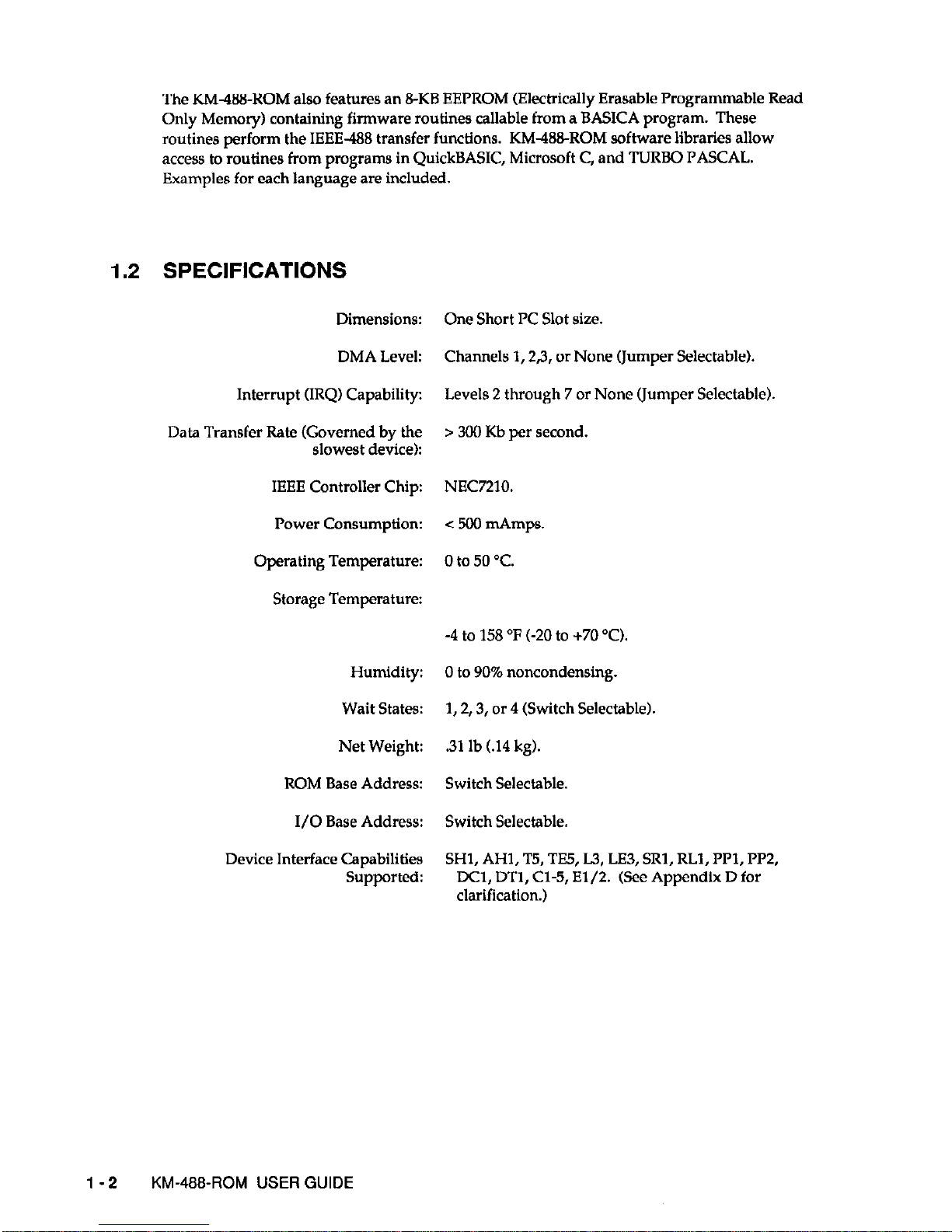
1.2
The KM-488-ROM also features an 8-KB EEPROM (Electrically Erasable Programmable Read
Only Memory) containing firmware routines callable from a BASICA program. These
routines perform the IEEE-488 transfer functions. KM-488ROM software libraries allow
access to routines from programs in QuickBASIC, Microsoft C, and TURBO PASCAL.
Examples for each language are included.
SPECIFICATIONS
Dimensions:
DMA Level:
Interrupt URQ) Capability:
Data Transfer Rate (Governed by the
slowest device):
IEEE Controller Chip:
Power Consumption:
Operating Temperature:
Storage Temperature:
Humidity:
Wait States:
Net Weight:
ROM Base Address:
I/O Base Address:
Device Interface Capabilities
Supported:
One Short PC Slot size.
Channels 1,2,3, or None (Jumper Selectable).
Levels 2 through 7 or None (Jumper Selectable).
> 300 Kb per second.
NEC7210.
< 500 mAmps.
0 to 50 T.
-4 to 158 ‘F (-20 to +70 “0.
0 to 90% noncondensing.
1,2,3, or 4 (Switch Selectable).
.31
lb (.14 kg).
Switch Selectable.
Switch Selectable.
SHl, AHI, T5, TE5, L.3, LE3, SRl, RLl, PPl, PP2,
DCl, DTl, Cl-5, E1/2. (See Appendix D for
clarification.)
1-2 KM-488~ROM USER GUIDE
Page 9
1.3 ORDERING INFORMATION
PARTNUMBER
DESCRIPTION
KM-488-ROM Includes the KM-488-ROM IEEE-488 Interface Board,
Software (on 5.25” disks), and appropriate
documentation.
KM-488-ROM/3.5 Includes the KM-488-ROM IEEE488 Interface Board,
Software (on 3.5” disks), and appropriate
documentation.
CGPIB-I 1 meter IEEE-488 cable.
CGPIB-2 2 meter IEEE-488 cable.
CGPIB-4 4 meter IEEE-488 cable.
1.4 HOW TO USE THIS MANUAL
This manual provides the information necessary to install and program the KM-488-ROM.
The manual assumes you are familiar with the language in which you are developing your
application program; it also assumes you are familiar with the IEEE-488 protocol.
Chapter 2, Installation, details how to unpack, inspect, configure, and install the KM-488
ROM and how to copy the accompanying software. Additionally, Chapter 2 describes how to
install the KM48EROM software and to configure the EEPROM and reload EEPROM
software. There are also notes on using multiple boards in one system.
Chapter 3, Zntroductfan fo the
CaRable Routines,
provides a brief functional description of each
KM488-ROM Interface Routine.
Chapter 4, Programming the
KM-488-ROM,
provides a detailed description of each KM-488-
ROM Interface Routine and how it is called from each of the supported languages:
BASICA,
QuickBASIC, C, and TURBO PASCAL.
Chapter 5, Factory Returns , gives instructions for returning the board to the factory.
The appendices contain additional useful information. Appendix A contains an ASCII
Equivalence Chart. This gives hex and
decimal
equivalents for the ASCII 128 Character set.
Appendix B is an IEEE-488 tutorial. Appendix C provides an explanation of the Device
Capability Identification codes. Appendix D provides a cross-reference chart of IEEE
Multiline Commands. Appendix E describes how to use the KM488-DD Printer Port Redirector.
INTRODUCTION 1 - 3
Page 10

0
l-4 KM-488-ROM USER GUIDE
Page 11
Chapter 2
INSTALLATION
2.1 GENERAL
Installation begins with procedures for unpacking and inspection followed by
recommendations and instructions for software. Next is a section on switch and jumper
settings. Board installation is the next step, followed by EEPROM configuration.
2.2 UNPACKING 81 INSPECTING
After removing the wrapped Board from its outer shipping carton, proceed as follows:
1. Before unwrapping the Board, place one hand firmly on a bare-metal portion of the
computer chassis to discharge static electricity from yourself and the Board (the computer
must be turned Off but grounded).
2. Carefully remove the Board fromits anti-static wrapping material. You may wish to save
the wrapping material for possible future use; if so, store it in a safe place.
3. Inspect the Board for signs of damage. If any damage is apparent, return the Board to the
factory.
4. Check the remaining contents of your package against the packing list to be sure your
order is complete. Report any missing items to the factory immediately.
5. When you are satisfied with preliminary inspection, you are ready to configure the Board.
Refer to the next section for configuration options.
2.3 SOFTWARE INSTALLATION
Backing Up The Distribution Software
As soon as possible, make a back-up copy of your Distribution Software. With one (or
more,as needed) formatted diskettes on hand, place your Distribution Sofhvare diskette in
your PC’s A Drive and log to that drive by typing A: . Then, make your backup using the
DOS
COPY
or
DISKCOPY
command, as described in your DOS reference manual
(DISKCOPY is preferred because it copies diskette identification, too).
installing The Distribution Software
Install the KM-488-ROM Distribution Software on your computer’s hard drive using the DOS
COPY command.
INSTALLATION 2 - 1
Page 12
NOTE: If you are using BASICA and the factory default settings, you may run the KM-
4%ROM board without installing any software. Instead, proceed to Section 2.4.
To install the software:
1. Turn on your PC and its display. You should see the standard DOS-level prompt.
NOTE: If you install example programs written in multiple languages, you may want to
create a directory for each language. (This is the way the Distribution Software is
organized.)
2. The following instructions create a directory named
KM488R. Type md \Rld488R
3. Change to the KM488Rdirectory by typing cd \KM488R
4. Place a KM-4&%ROM Diskette into the floppy drive (assume this is Drive a:) and type
copy a:*.*
Repeat this step for each disk and/or subdirectory, until copying is complete.
Distribution Software Contents
Your Distribution Software contains the file
FILESDOC
, an ASCII text file readable with any
text editor or with the DO!?
TYPE
command. FlLES.DOC lists and briefly describes all files
in the Distribution Software.
The README.DOC File
To learn of last-minute changes, be sure to read the ASCII file
READMEDOC
2.4 SWITCHES & JUMPERS
Factory Settings
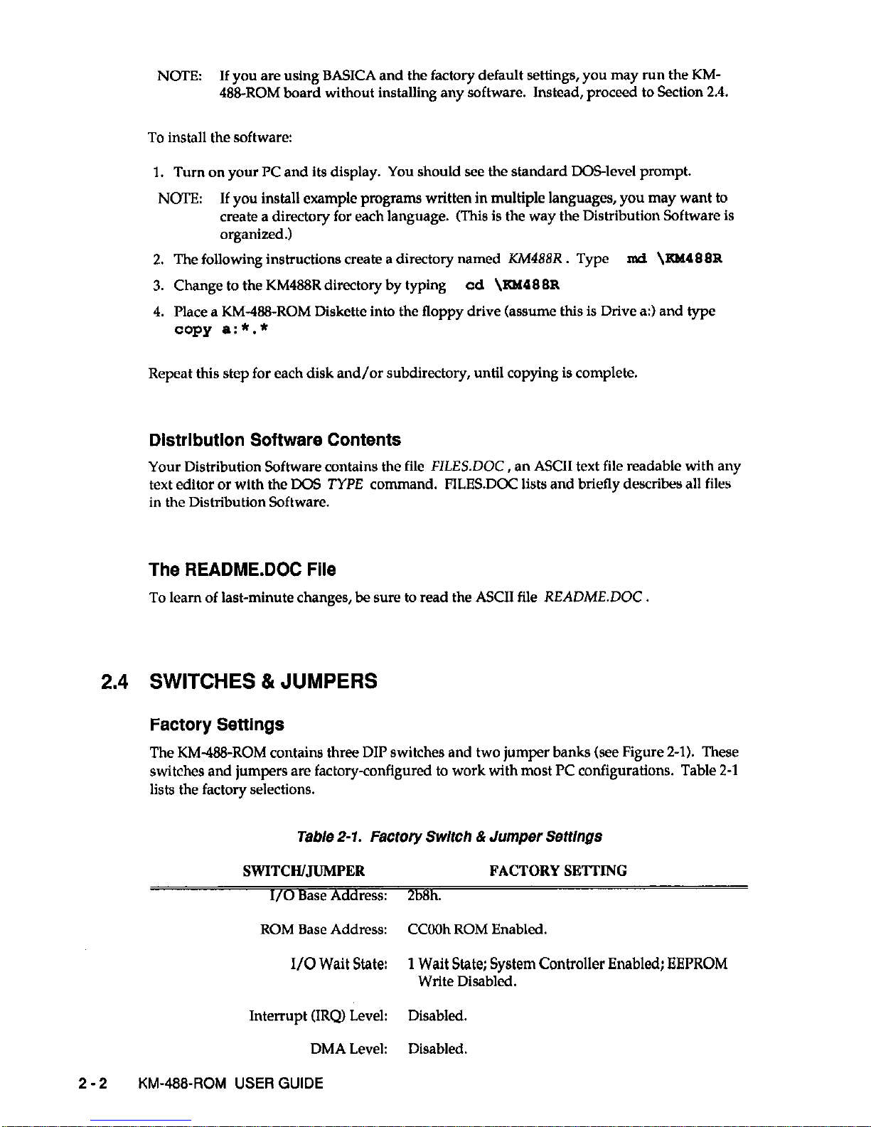
The KMG%-ROM contains three DIP switches and two jumper banks (see Figure 2-l). These
switches and jumpers are factory-configured to work with most PC configurations. Table 2-l
lists the factory selections.
Table 2-1. Factory Switch & Jumper Settlngs
SWITCH/JUMPER
FACTORY SE’ITING
I/O Base Address: 2b8h.
ROM Base Address: CCOOh ROM Enabled.
I/O Wait State:
1 Wait State; System Controller Enabled; EEPROM
Write Disabled.
Interrupt (IRQ) Level: Disabled.
DMA Level: Disabled.
2-2 KM-488~ROM USER GUIDE
Page 13
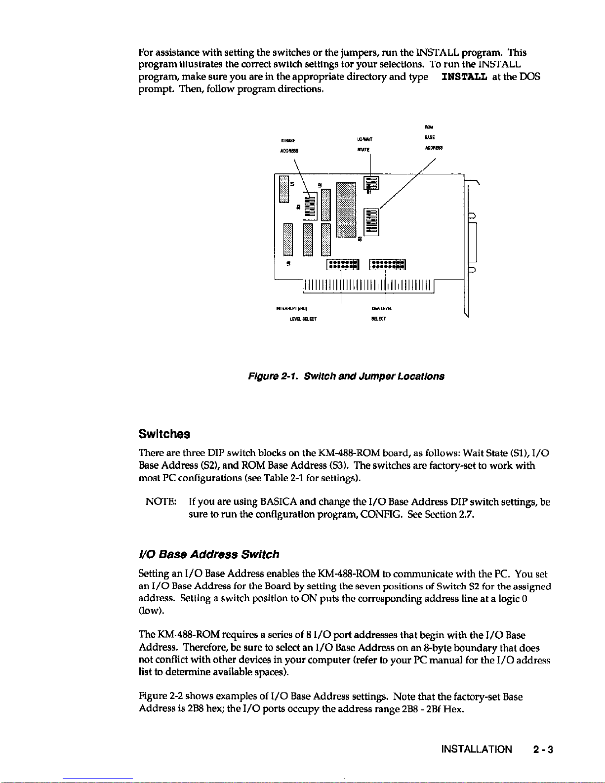
For assistance with setting the switches or the jumpers, run the INSTALL program. This
program illustrates the correct switch settings for your selections. To run the INSTALL
program, make sure you are in the appropriate directory and type INSTALL at the DOS
prompt. Then, follow program directions.
Figure 2-1. Switch and Jumper Locatlons
Switches
There are three DIP switch blocks on the KM48-ROM board, as follows: Wait State (Sl), I/O
Base Address (S2), and ROM Base Address 63). The switches are factory-set to work with
most PC configurations (see Table 2-l for settings).
NOTE: If you are using BASICA and change the I/O Base Address DIP switch settings, be
sure to run the configuration program, CONFIG. See Section 2.7.
I/O Base Address Switch
Setting an I/O Base Address enables the KM-488-ROM to communicate with the PC. You set
an I/O Base Address for the Board by setting the seven positions of Switch S2 for the assigned
address. Setting a switch position to ON puts the corresponding address line at a logic 0
(low).
The KM-488-ROM requires a series of 8 I/O port addresses that begin with the I/O Base
Address. Therefore, be sure to select an I/O Base Address on an B-byte boundary that does
not conflict with other devices in your computer (refer to your PC manual for the I/O address
list to determine available spaces).
Figure 2-2 shows examples of I/O Base Address settings. Note that the factory-set Base
Address is 288 hex; the I/O ports occupy the address range 288 - 2Bf Hex.
INSTALLATION
2-3
Page 14
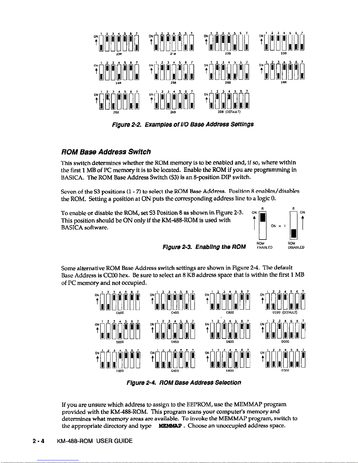
FIgore 2-2. Examples of l/O Base Address SeftlngS
ROM Base Address Switch
This switch determines whether the ROM memory is to be enabled and, if so, where within
the first 1 MB of PC memory it is to be located. Enable the ROM if you are programming in
BASICA. The ROM Base Address Switch 63) is an B-position DIP switch.
Seven of the S3 positions (1 - 7) to select the ROM Base Address. Position 8 enables/disables
the ROM. Setting a position at ON puts the corresponding address line to a logic 0.
To enable or disable the ROM, set 53 Position 8 as shown in Figure 2-3.
This position should be ON only if the KM-W-ROM is used with
BASICA software.
Flgure 2-3. Enabllng the ROM ~%B,EO %&LED
Some alternative ROM Base Address switch settings are shown in Figure 2-1. The default
Base Address is CC00 hex. Be sure to select an 8 KB address space that is within the first 1 MB
of PC memory and not occupied.
Flgure 2-4. ROM Base Address Selectlon
If you are
unsure
which address to assign to the EEPROM, use the MEMMAP program
provided with the KM-488-ROM. This program scans your computer’s memory and
determines what memory areas are available. To invoke the MEMMAI’ program, switch to
the appropriate directory and type
m . Choose an unoccupied address space.
2-4 KM-488-ROM USER GUIDE
Page 15
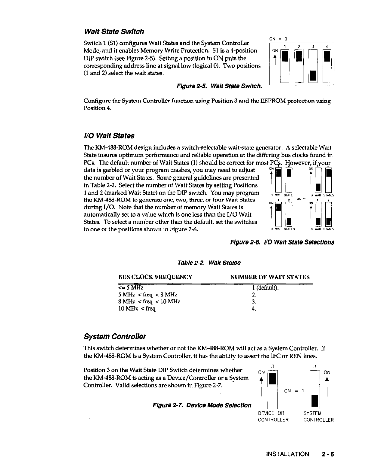
Wait State Switch
Switch 1 (Sll configures Wait States and the System Controller
ON = 0
Mode, and it enables Memory Write Protection. Sl is a 4-position
DIP switch (see Figure 2-5). Setting a position to ON puts the
corresponding address line at signal low (logical 01. Two positions
(1 and 21 select the wait states.
Flgure 2-5. Welt State Switch.
Configure the System Controller function using Position 3 and the EEPROM protection using
Position 4.
I/O Waif States
The KM-B&ROM design includes a switch-selectable wait-state generator. A selectable Wait
State insures optimum performance and reliable operation at the differing bus clocks found in
PCs. The default number of Wait States (11 should be correct for most PCs. vowever, if,youf
data is garbled or your program crashes, you may need to adjust
the number of Wait States. Some general guidelines are presented
in Table 2-2. Select the number of Wait States by setting Positions
1 and 2 (marked Wait State) on the DIP switch. You may program
‘03 911’1
, w*,, STATE , w*l, STITFS
the KM468-ROM to generate one, two, three, or four Wait States
during
I/O. Note that the number of memory Wait States is
automatically set to a value which is one less than the I/O Wait
States. To select a number other than the default, set the switches
to one of the positions shown in Figure 2-6.
iE~Yg~
2 WNT sTME9 4 WIT STATES
Figure 2-6. t/O
Walt
State Seiectlons
Table 2-2. Welt States
BUS CLOCK FREQUENCY NUMBER OF WAIT STATES
<=5MHz
1 (default).
5MHz <ticq <8MHz
2.
8MHz <freq < 10MHz
3.
10 MHz < freq
4.
System Controller
This switch determines whether or not the KM488-ROM will act as a System Controller. If
the KM-488-ROM is a System Controller, it has the ability to assert the IFC or REN lines.
Position 3 cm the Wait State DIP Switch determines whether
3 ON
the KM-438-ROM is acting as a Device/Controller or a System
Controller. Valid selections are shown in Figure 2-7.
ON i
ON = 1
Figure 2-7. Device Mode Selection
II 1’
DEVICE OR SYSTEM
CONTROLLER
CONTROLLER
INSTALLATION 2 - 5
Page 16
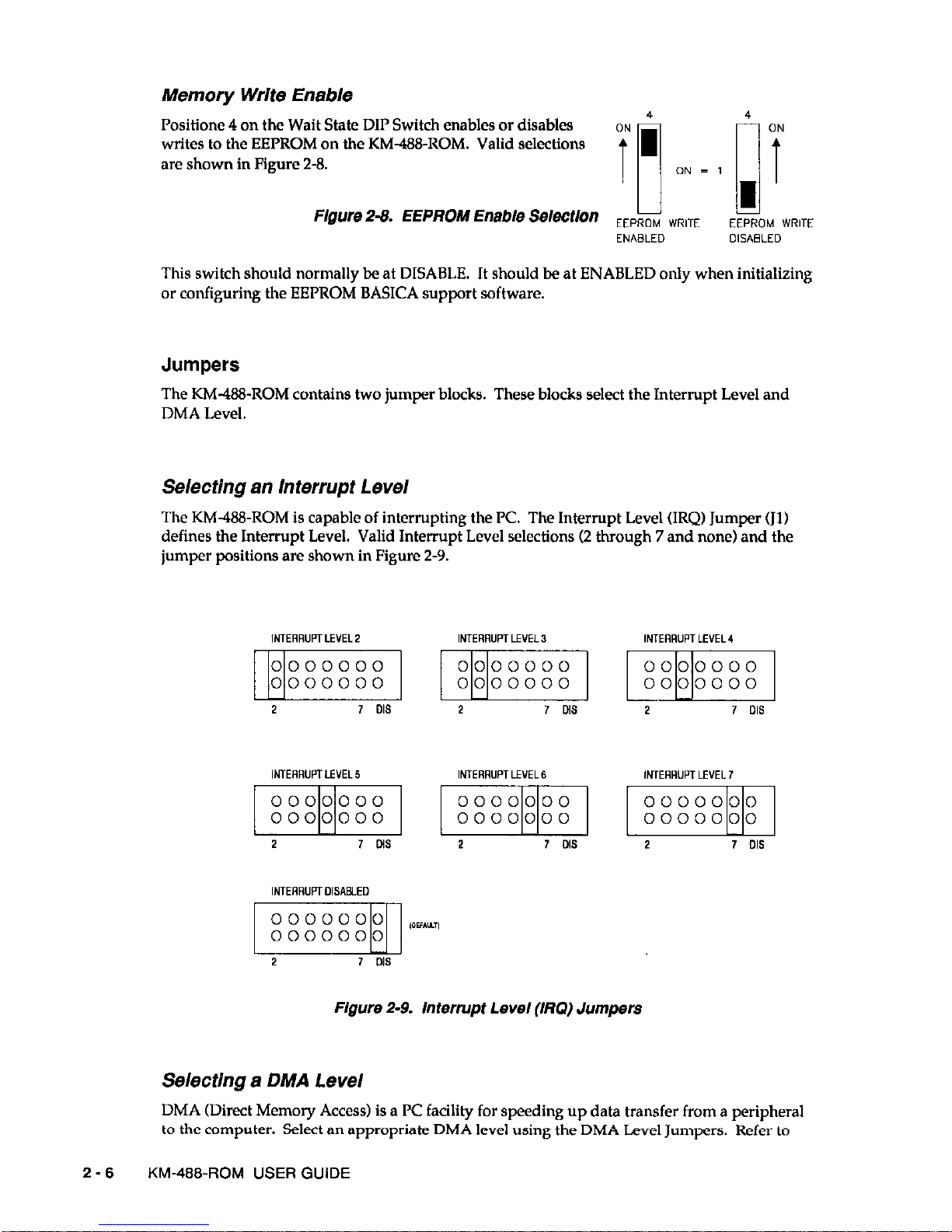
Memory Write Enable
Positlone 4 on the Wait State DIP Switch enables or disables
writes to the EEPROM on the KM488-ROM. Valid selections
are shown in Figure 2-8.
Flgure2-8. EEPROM Enable Selection
EEPROM WR,TE
EEPROM WRITE
ENABLED
DlSABLED
This switch should normally be at DISABLE. It should be at ENABLED only when initializing
or configuring the EEPROM BASICA support software.
Jumpers
The KM-ltlE-ROM contains two jumper blocks. These blocks select the Interrupt Level and
DMA Level.
Selecting an Interrupt Level
The KM-@&ROM is capable of interrupting the PC. The Interrupt Level (IRQ) Jumper (Jll
defines the Interrupt Level. Valid Interrupt Level selections (2 through 7 and none) and the
jumper positions are shown in Figure 2-9.
Figure 2-9. Interrupt Level (Ml) Jumpers
Selecting a DMA Level
DMA (Direct Memory Access) is a PC facility for speeding up data transfer from a peripheral
to the computer. Select an appropriate DMA level using the DMA Level Jumpers. Refer to
2-6
KM-488-ROM USER GUIDE
Page 17
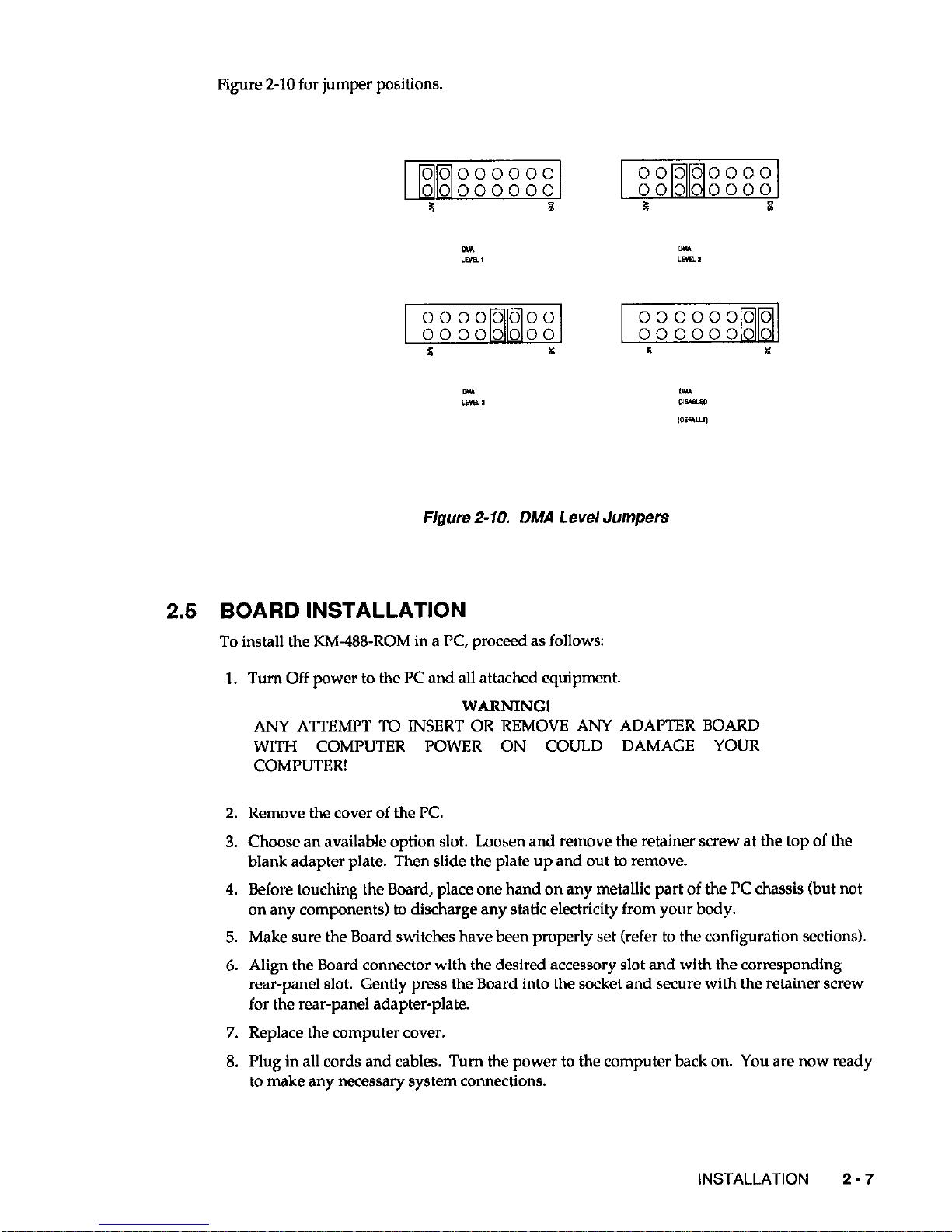
Figure 2-10 for jumper positions.
F/gum 2-10. DMA Level Jumpers
2.5 BOARD INSTALLATION
To install the KM-488-ROM in a PC, proceed as follows:
1. Turn Off power to the PC and all attached equipment.
WARNING!
ANY ATTEMPT TO INSERT OR REMOVE ANY ADAPTER BOARD
WITH COMPUTER POWER ON COULD DAMAGE YOUR
COMPUTER!
2. Remove the cover of the PC.
3. Choose an available option slot. Loosen and remove the retainer screw at the top of the
blank adapter plate. Then slide the plate up and out to remove.
4. Before touching the Board, place one hand on any metallic part of the PC chassis (but not
on any components) to discharge any static electricity from your body.
5. Make sure the Board switches have been properly set (refer to the configuration sections).
6. Align the Board connector with the desired accessory slot and with the corresponding
rear-panel slot. Gently press the Board into the socket and secure with the retainer screw
for the rear-panel adapter-plate.
7. Replace the computer cover.
8. Plug in all cords and cables. Turn the power to the computer back on. You are now ready
to make any necessary system connections.
INSTALLATION 2 - 7
Page 18

If you are developing KM488-ROM application programs in C, TURBO PASCAL or
QuickBASIC, the installation process is now complete. However, if you are developing
programs in BASICA and have changed the factory default settings, you must to run the
EEI’ROM configuration program CONFIG.
2.6
CONFIGURATION OF THE EEPROM
When KM488-ROM application programs use BASICA, the programs read interface
functions directly from the on-board EEPROM. Thus, the EEPROM must be properly
configured, which may be accomplished using the CONFIG program. This program allows
you to change such parameters of the EEPROM configuration as I/O Base Address, l/O
Timeout, DMA Timeout, and Transmit/Receive Terminators.
Before changing the EEPROM configuration, you may want to read the descriptions of the
DMA, RCV, and XMIT routines in Chapter 3. Also make sure that the ROM Base Address
switch has the ROM Write function enabled. (See Section 2.4.)
Invoking The CONFIG Program
Invoke the CONFIG program as follows:
1. Install the Distribution Software (see Section 2.3) and the KM488-ROM board (see Section
2.5).
2. Switch to the appropriate directory. At the DOS prompt, type CONFIG
The PC monitor will show a screen labelled
K&-488-ROM CONFIGURATION. The
settings
will reflect any changes which were made by running the INSTALL program.
The following PC function keys are now active:
[E-II
[ml
[F31
I Shift II F3 I
[AltI[F31
[F81
HELP Invoke Help at any time by pressing [ Fl ]
SHOW NEXT. In multiple board systems, pressing [ Fl I shows the
configuration of the next KM488-ROM.
LOAD . Pressing this key loads the file KM488ROM.BlN to the EEPROM.
This function is useful when you want to load the factory defaults back
into the KM488-ROM’s EEPROM.
LOAD NEW MEMORY. Pressing this key combination allows you to
load the contents of the KM488-ROM’S EEPROM to a new segment of
DOS memory. The value you enter here must agree with the address
selected by the ROM Base Address Switch. If you have trouble identifying
an unoccupied space, run the MEMMAP program (see Section 2.4).
EDIT I/O ADDRESS. This key combination permits you to edit the I/O
Address field only. This
is
the address for access to the KM488-ROM. It
is important that you select an l/O Base Address on an S-byte boundary
that
does not conflict with other devices in your computer. The I/O Base
Address must fall within the range 200h to 3F8h.
EDIT. This key allows editing of the configuration parameters (see the
next section for parameter descriptions). When editing is complete, press
1 MO 1. When the prompt Save changes to KM-488-ROM memory? Y/N
appears, enter the appropriate response.
2-8 KM-488-ROM USER GUIDE
Page 19
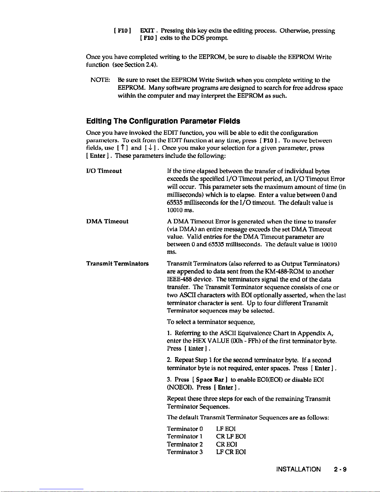
[ FlO I EXIT. Pressing this key exits the editing process. Otherwise, pressing
[ FlO I exits to the DOS prompt.
Once you have completed writing to the EEPROM, be sure to disable the EEPROM Write
function (see Section 2.4).
NmEz Be sure to reset the EEPROM Write Switch when you complete writing to the
EEI’ROM. Many software programs are designed to search for free address space
within the computer and may interpret the EEPROM as such.
Editing The Configuration Parameter Fields
Once you have invoked the EDIT function, you will be able to edit the configuration
parameters. To exit from the EDIT function at any time, press I FlO
1.
To move between
fields, use [ ? I and [ J I . Once you make your selection for a given parameter, press
[ Enter 1 These parameters include the following:
DMA Timeout
I/O Timeout If the time elapsed between the transfer of individual bytes
exceeds the specified I/O Timeout period, an I/O Timeout Error
will occur. This parameter sets the maximum amount of time (in
milliseconds) which is to elapse. Enter a value between 0 and
65535 milliseconds for the I/O timeout. The default value is
10010 Ins.
A DMA Timeout Error is generated when the time to transfer
(via DMA) an entire message exceeds the set DMA Timeout
value. Valid entries for the DMA Timeout parameter are
between 0 and 65535 milliseconds. ‘Ihe default value is 10010
Ins.
Transmit Terminators
Transmit Terminators (also referred to as Output Terminators)
are appended to data sent from the KM-488-ROM to another
IEEE-488 device. The terminators signal the end of the data
transfer. The Transmit Terminator sequence consists of one or
two ASCII characters with EOI optionally asserted, when the last
terminator character is sent. Up to four different Transmit
Terminator sequences may be selected.
To select a terminator sequence,
1. Referring to the ASCII Equivalence Chart in Appendix A,
enter the HEX VALUE @Oh - FFh) of the first terminator byte.
Press [ Enter I .
2. Repeat Step 1 for the second terminator byte. If a second
terminator byte is not required, enter spaces. Press [ Enter ] .
3. Press 1 Space Bar 1 to enable EOI(EO1) or disable EOI
(NOEOI). Press [ Enter I .
Repeat these three steps for each of the remaining Transmit
Terminator Sequences.
The default Transmit Terminator Sequences are as follows:
Terminator 0
LF EOI
Terminator 1 CR LF EOI
Terminator 2
CR EOI
Terminator 3
LF CR EOI
INSTALLATION
2 - 9
Page 20

Receive Terminators The KM488-ROM uses these items (also referred to as Input
Terminators.) to detect the end of a data transfer received from
another device. The Receive Terminator sequence consists of
one ASCII character with EOI optionally asserted. If the chosen
terminator character is detected in the incoming data, reception
will terminate. Note that any data byte received with EOI
asserted will always terminate reception, regardless of the
selected terminator.
Up to four different Receive Terminator sequences are available
for selection, as follows:
Terminator 0
LF EOI
Terminator I
CR EOI
Terminator 2 , (comma) EOI
Terminator 3
; (semi-colon) EOI
To change the terminator character, use the procedure
previously outlined for Transmit Terminators.
2.7 RELOADING THE EEPROM
Under some conditions (for example, if the EEPROM contents have been destroyed), you will
have to reload the EEPROM with the contents of the Kh4488ROM.BIN file. To perform this
requirement, run the CONFIG program, as described in the previous section.
Before you reload the EEPROM, be sure its Write/Enable switch is enabled (see Section 2.4).
The proceed as follows:
1. Invoke the CONFIG program. Switch to the appropriate directory and at the DOS
prompt, type CONFIG.
2. Press [ F3 I.
When you completed the EEPROM reload, be sure to disable the EEPROM Write Enable
switch (see Section 2.4).
2.8 MULTIPLE BOARD INSTALLATION NOTES
The KM-483-ROM software allows installation of up to four boards in a given system.
Typically, situations with excessive cable lengths or more than 14 instruments require
multiple boards.
When using multiple Kh4-488-ROMs, set the I/O Port Base Address to a different value on
each of the boards. Routines within the software library allow you to determine which board
to use by specifying the Base Address of the I/O port on that board.
When using BASICA, each board requires its own copy of software.
This means that you
must select a different EEI’ROM memory address and I/O Base Address for each board.
These Base Address ranges CANNOT overlap other address ranges within the system.
2-10
KM-4WROM USER GUIDE
Page 21

Chapter 3
INTRODUCTION TO CALLABLE ROUTINES
To use the KM488-ROM within a custom data acquisition or control environment, you have
to write software that will access the GPIB. The KM488-ROM includes a number of “callable”
routines allowing this access from high-level languages such as BASIC, Quick BASIC, C, and
TURBO PASCAL.
This chapter describes the callable-interface routines from a functional approach. Chapter 4
provides the exact syntax for calling the routine from BASIC, Quick BASIC, C, and TURBO
PASCAL. Table 3-l provides an alphabetical listing of the available routines. The remainder
of the chapter tracks the order of a routine’s usage and is organized as follows:
l
Initializing the KM488-ROM.
. Selecting the Receive and Transmit Message Terminators.
l
Transmitting Commands and Data.
l
Reading Data.
l
Transmitting/Receiving Data via DMA.
l
Checking the Status of a Device.
l
Low-level Routines.
l
Configuring the Board.
NOTE:
Explanations within this chapter assume you are familiar with IEEE486
communications. If you are new to IEEE488 or do not recognize some of the
terminology used, refer to the IEEE488 Tutorial in Appendix B.
INTRODUCTION TO CALLABLE ROUTINES
3-1
Page 22
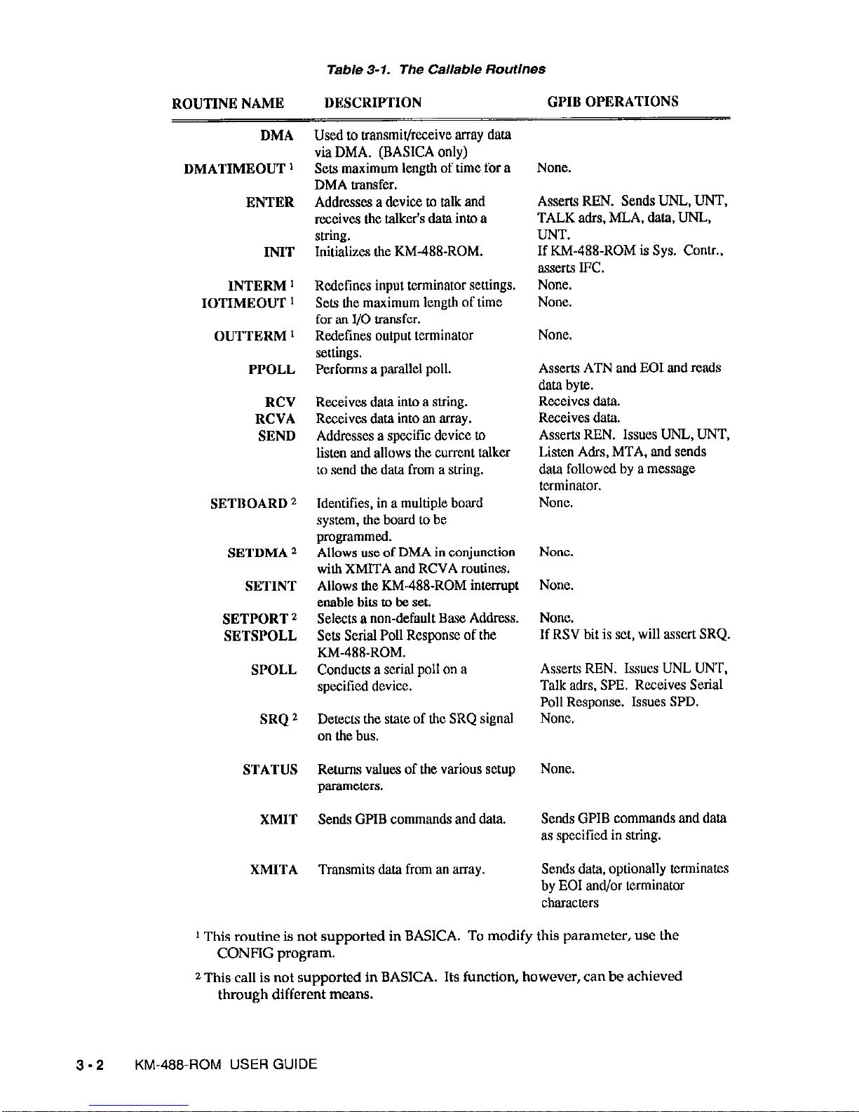
Table 3-1. The Callable RoutlnSS
ROUTINE NAME
DESCRIPTION
GPIB OPERATIONS
DMA
DMATIMEOUT ’
ENTER
INIT
INTERM ’
IOTIMEOUT 1
OUTTERM ’
PPOLL
RCV
RCVA
SEND
SETBOARD 2
SETDMA 2
SETINT
SETPORT 2
SETSPOLL
SPOLL
SRQ 2
STATUS
XMIT
XMITA
Used to transmit/receive array data
via DMA. (BASICA only)
Sets maximum length of time for a
DMA transfer.
Addresses a device to talk and
receives the talker’s data into a
suillg.
Initializes the KM-488-ROM.
Redefines input terminator settings.
Sets the maximum length of time
for an I/O transfer.
Redefines output terminator
settings.
Performs a parallel poll.
Receives data into a string.
Receives data into an array.
Addresses a specific device to
listen and allows the current talker
to send the data from a string.
Identifies, in a multiple board
system, the board to be
programmed.
Allows use of DMA in conjunction
with XMITA and RCVA routines.
Allows the KM-488~ROM interrupt
enable bits to be set.
Selects a non-default Base Address.
Sets Serial Poll Response of the
KM-488-ROM.
Conducts a serial poll on a
specified device.
Detects the state of tic SRQ signal
on the bus.
Returns values of the various setup
parameters.
Sends GPIB commands and data.
Transmits data from an array.
Asserts REN. Sends UNL, UNT,
TALK adrs, MLA, data, UNJ-,
LINT.
If KM-48%ROM is Sys. Contr.,
assert.9 IFC.
None.
None.
None.
Asserrs ATN and EOI and reads
data byte.
Receives data.
Receives data.
Asserts RBN. Issues UNL, UNT,
Listen Adrs, MTA, and sends
data followed by a message
terminator.
None.
None.
If RSV bit is set, will sssert SRQ.
Asserts REN. Issues UNL UNT,
Talk adrs, SPE. Receives Serial
Poll Response. Issues SPD.
None.
Sends GPIB commands and data
as specified in string.
Sends data, optionally terminates
by EOI and/or terminator
characters
1 This routine is not supported in BASICA. To modify this parameter, use the
CONFIG program.
2 This call is not supported in BASICA. Its function, however, can be achieved
through different means.
3-2
KM-485ROM USER GUIDE
Page 23
3.1 INITIALIZING THE KM-488-ROM
The first step in any KM488-ROM application program is to initialize the KM488-ROM
board(s), using the lNIT routine.
3.2
INIT
This routine configures the KM4?8-ROM as a device or a controller. INIT also defines the
Gl’IB address and determines whether Bus Handshaking is to be High or Low Speed. If INIT
designates the KM-488-ROM as a System Controller, the Interface Clear (IF0 line on the GPIB
is asserted momentarily when INIT is called.
Either High or Low Speed Handshaking is available. In High Speed mode, the KM-488~ROM
asserts the GPIB bus signal DAV approximately 500 ns after data is placed onto the bus. In
the low speed mode, DAV is asserted about 2 microseconds after the data. In most cases, you
will see no apparent differences in data throughput with Low Speed Handshaking. To
maximize data throughput when using DMA, select High Speed Handshaking.
NOTE: Use the High Speed mode only in smaller installations, because High Speed
Handshake mode allows less time for data to settle. Thus, as cable lengths
increase, the probability of transmission errors from cable reflections will increase.
NOTE: INIT must be the first KM-488-ROM routine called within the program.
lOTIMEOUT
This routine is not usable in BASICA. IOTIMEOUT allows you to reset the length of time that
is to elapse before a Timeout Error occurs. A timeout Error occurs when the time between
transmission and reception of adjacent bytes exceeds the set time. (I/O Timeout Error reports
occur when using SEND, ENTER, XMITA, XMIT, and RCVA calls without DMAJ The
default value of the timeout period is 10 seconds.
NOTE: The I/O Timeout may be changed at any point in the program.
SELECTING THE RECEIVE 81 TRANSMIT TERMINATORS
When data is transmitted to or from the KM-488-ROM, it may contain message terminator
characters. These terminator characters are used to signal the end of data transmission.
Every KM-488-ROM routine that transmits or receives data contains a parameter allowing you
to define which of the default terminator sequences is to be used. If your application program
is in C, QuickBASIC, or Turbo PASCAL, you may change the default terminator sequences by
calling the INTERM and OUTIERM routines.
If you are programming in BASICA, you may change the default Transmit/Receive
Terminator sequences and the I/O Timeout period only by running the CONFIG program
(see Sections 2.6 and 2.7).
INTRODUCTION TO CALLABLE ROUTINES
3 - 3
Page 24
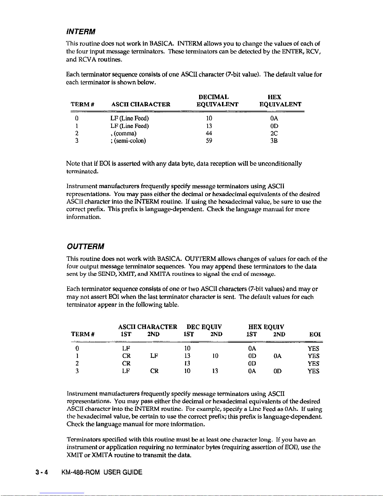
INTERM
This routine does not work in BASICA. INTERM allows you to change the values of each of
the four input message terminators. These terminators can be detected by the ENTER, RCV,
and RCVA routines.
Each terminator sequence consists of one ASCII character (7-bit value). The default value for
each terminator is shown below.
DECIMAL HEX
TERM # ASCII CHARACTER EQUIVALENT
EQUIVALENT
0
LF (Lime Feed) 10 OA
1 LF (Line Feed) 13 OD
2 , (comma) 44 2c
3 : (semi-colon) 59 3B
Note that if EOI is asserted withany data byte, data reception will be unconditionally
terminated.
Instrument manufacturers frequently specify message terminators using ASCII
representations. You may pass either the decimal or hexadecimal equivalents of the desired
ASCII character into the INTERM routine. If using the hexadecimal value, be sure to use the
correct prefix. This prefix is language-dependent. Check the language manual for more
information.
OUTTERM
This routine does not work with BASICA. OUTTERM allows changes of values for each of the
four output message terminator sequences. You may append these terminators to the data
sent by the SEND, XMIT, and XMITA routines to signal the end of message.
Each terminator sequence consists of one or two ASCII characters (irbit values) and may or
may not assert EOI when the last terminator character is sent. The default values for each
terminator appear in the following table.
ASCII CHARACTER DEC EQUIV
HEX EQUIV
TERM # IST ZND 1ST
2ND
1ST 2ND
EOI
0 LF 10 OA YES
1 CR LF 13 10 OD OA YES
2 CR 13 OD YES
3 LF CR 10 13 OA OD YES
Instrument manufacturers frequently specify message terminators using ASCII
representations. You may pass either the decimal or hexadecimal equivalents of the desired
ASCII character into the INTERM routine. For example, specify a Line Feed as OAh. If using
the hexadecimal value, be certain to use the correct prefix; this prefix is language-dependent.
Check the language manual for more information.
Terminators specified with this routine must be at least one character long. If you have an
instrument or application requiring no terminator bytes (requiring assertion of EOI), use the
XMIT or XMITA routine to transmit the data.
3-4
KM-488~ROM USER GUIDE
Page 25
3.3
TRANSMllTlNG COMMANDS AND DATA
Once the GPIB system is initialized, the next step is usually to send commands and/or data to
a device. Use any of the following routines to send:
l
SEND
l
XMIT
l
XMITA
l
IOTIMEOUT
SEND
Use this routine only when the KM488-ROM is an Active Controller.
SEND transfers string
data from the KM488-ROM to the device specified by first addressing the KM488-ROM as a
talker and the indicated device as a listener, and then asserting the REN line. Next, the
command sends the string, followed by the selected message terminator, to the listener. The
routine returns a status variable indicating whether or not the transfer is properly completed.
XMIT
The XMIT Routine allows the greatest amount of flexibility for sending GPIB commands (see
Section 3.4.) and data. Data and commands to be sent over the GLIB are expressed in string
form and then passed into the XMIT routine. All commands within the string may be UPPER
or lower case; but they must be separated by one or more spaces.
If the KM488-ROM is acting as a Controller, the XMIT routine sends both commands and
data. If executing the XMIT routine, the KM488-ROM must
l
Untalk and Unlisten all Devices.
l
Assign a Listener.
l
Address itself as a Talker.
If, however, the KM488-ROM is acting as a Device, the XMIT routine can only send data. In
this instance, the KM488-ROM must be a talker before the XMIT routine can execute.
The XMIT routine will then parse the string and extract and send the commands over the bus
in the specified sequence. The commands to carry out this sequence can all be within a single
string and handled by a single call to the XMIT routine.
The XMIT routine returns a single status variable to indicate the state of the data transfer.
XMIT will report cases of invalid syntax, invalid address, undefined commands, timeout
errors, and attempts to send bus commands while not the active controller.
THE XMIT COMMANDS
Send these commands in the XMIT command’s info string; they consist of rudimentary GPIB
and other commands and separate by function into three categories, as follows:
1. Data Transmission.
2. Polling.
3. Miscellaneous.
INTRODUCTION TO CALLABLE ROUTINES
3 - 5
Page 26
DATA
END
EOI
GTL
Use this command after the KM-488-ROM has been addressed to talk. (If
the KM-488-ROM is controller, issue an MTA. Otherwise, the Controller
must address the KM-488-ROM. See the STATUS routine description for
more information.) DATA sends the message that trails it to all previously
addressed listeners.
Data may be in two forms. In one form, data is a string of ASCII
characters that trails the DATA command. The ASCII string will be in
single quotes (for example, ‘BYE’).
In the other form, data may be a string of numeric values, each of which
ranges from 0 to 255. Each numeric value is the decimal equivalent of an
ASCII character (see Appendix A for ASCII Equivalents). One or more
spaces must separate each numeric entry. This form of entry is useful
where transmission of nonprintable characters is required. Note that you
may switch freely between the ASCII and Decimal representations after
the DATA command, as long as ASCII characters are in a string enclosed
by single quotes.
EXllmple
DATA ‘Eello’ 13 10
DATA
'Line
1’
13
10 ‘Line 2’ 13 10
If END follows the DATA command string, Message Terminator 0 signals
the End of Transmission. Section 3.2 describes the default values of the
transmit terminators and how to change them. Set the terminators to one
or two bytes, and send them with or without EOI asserted on the last byte.
Example
DATA ‘Eello’ END
If EOI (END OR IDENTIFY) follows the DATA command string, it
indicates that the character following EOI mnemonic will be sent with the
EOI line asserted.
Example
DATA ‘Hello’ 13 EOI 10
The GTL command forces bus devices addressed to listen to the Go To
Local (front panel controllable) state, as opposed to controlled via Gl’lB.
This command also onasserts the REN signal on the GPIB. Only the
System Controller may use GTL. Note that this command DOES NOT
allow you to selectively force only one device to Go To Local.
Note that it is more practical to use GTLA and LOC commands than GTL.
Example
GTL
3-6
KM-488~ROM USER GUIDE
Page 27
GTLA Only a KM488-ROM acting as a System Controller may issue this
command. Use this command is used to send a Go To Local (GTL) Gl’lB
command to those
devices
previously addressed to listen. This command
does not affect the state of the GPIB REN line.
Example
GTLA
LISTEN The KM488-ROM must be the Active Controller to execute this command.
This command addresses a given device(s) as a listener(s). LISTEN is
trailed by the decimal GPIB address (0 to 30) of the device(s) to be
addressed. When assigning multiple listeners, separate the addresses by
one or more spaces.
Note that it is good practice to untalk and unlisten all devices prior to
sending a LISTEN command. (See the IJNT and IJNL descriptions.)
Example
LISTEN 2
LISTEN 5 9 30
LOC Use this command only if the KM488-ROM is acting as the System
Controller. When the LOC command is executed, it unasserts the GPIB
RBN (Remote Enable) line. This action forces all devices on the GI’IB to
the local state.
Example
LOC
MLA The KM488-ROM must be the Active Controller to execute MLA (My
Listen Address). MLA forces the KM488-ROM to become a listener; it
sends a listen address co
mmand containing the GPIB address of the KM-
485ROM over the GPIB.
Example
b5A
MTA The KM-Q@-ROM must be the Active Controller to execute MTA (My Talk
Address). MTA makes the KM488-ROM the present talker (and
onaddresses any other talker); it sends a talk address command containing
the address of the KM488-ROM over the GPIB.
Example
MTA
REN This command can function only if the KM488-ROM is the System
Controller. The REN command asserts the REN (Remote Enable) Control
line on the IEEE-488 bus. Many devices require REN to be asserted before
they will accept commands or data.
Example
INTRODUCTION TO CALLABLE ROUTINES 3 - 7
Page 28
3-8
SEC Use thls command in conjunction with TALK and LISTEN to specify a
secondary address. SEC must appear immediately after the primary
address in a TALK or LISTEN command. The KM488-ROM must be an
Active Controller to use SEC.
Example
TALK 3 SEC 5
LISTEN 4 SEC 8
TO If this command follows the DATA command, a Transmit Message
Terminator 0 will signal the end of data transmission. Section 3.2
describes the default values of the transmit terminators and how to change
them. Set the terminators to one or two bytes, and send with or without
EOI asserted on the last byte.
Example
DATA ‘Eello’ TO
Tl
If this command follows the DATA command, Transmit Message
Terminator 1 will signal the end of data transmission. Section 3.2
describes the default values of the transmit terminators and how to change
them. Set the terminators to one or two bytes, and send with or without
EOI asserted on the last byte.
Example
DATA
‘Eello’ Tl
T2
If this command follows the DATA command, Transmit Message
Terminator 2 will signal the end of data transmission. Section 3.2
describes the default values of the transmit terminators and how to change
them. Set the terminators to one or two bytes, and send with or without
EOI asserted on the last byte.
Example
DATA 'Eello' T2
T3 If this command follows the DATA command, Transmit Message
Terminator 3 will signal the end of data transmission. Section 3.2
describes the default values of the transmit terminators and how to change
them. Set the terminators to one or two bytes, and send with or without
EOI asserted on the last byte.
Example
DATA 'Eello' T3
TALK The KM488-ROM must be the Active Controller to execute this command.
TALK designates the specified device as a Talker and is followed by the
decimal GPIB address ( 0 to 30) of the device. Remember that only one
device can talk at a given time; thus, if multiple TALK commands are in a
command string, only the last one takes effect. Note that it is good
practice to untalk and u&ten all devices prior to sending a TALK
command (see the UNT and UNL descriptions).
Example
TALK1
TALK 22
KM-488.ROM USER GUIDE
Page 29

UNT. The KM488-ROM must be the Active Controller to execute this command.
UNLISTEN unaddresses the present listeners, if any.
Example
DNL
UNT The KM488-ROM must be the Active Controller to execute this command.
UNTALK is used to unaddress the present talker, if any.
Example
UNT
POLLING COMMANDS
PPC
PPD
PPU
SPD
The Parallel Poll Configure (PPC) command signals a previously
addressed listener that a Parallel Poll Enable @‘FE) byte or Parallel Poll
Disable (PI’D) command is to follow. Note that not all devices support
parallel polling.
PPC is rudimentary GPIB command byte and is thus sent using the CMD
command (see Miscellaneous Commands). The CMD command
immediately follows the PPC command; for example,
PPC
c&m nnn
Where nnn is the decimal value of the Parallel Poll Enable byte. This byte
has the following
format:
OllOSPPP
Where S is 0 or 1. The addressed device will set the designated GPIB
data line (determined by PPP) to the given value if service is required.
PPP
is a 3-bit value which represents a GI’IB data line (0 - 7). The
configured device will use this data line to respond to a parallel poll.
Eurmple
UNL LISTEN 6
MTA
PPC CbfD 101
The PPD (Parallel Poll Disable) command disables parallel poll response
of any previously addressed listeners. PPD must always immediately
follow a PPC.
Example
DNL LISTEN 12
MTA
PPC PPD
The I’I’U (Parallel Poll Unconfigure) command disables the parallel poll
response of all devices on the bus.
Example
PPV
The Serial Poll Disable (SPD) command returns the currently addressed
talker from the serial poll state to the “normal” talker state.
Example
SPD
INTRODUCTION TO CALLABLE ROUTINES 3 - 9
Page 30
SPE The Serial Poll Enable (WE) command forces a device, previously
addressed to talk, to send its serial poll response instead of its normal
data.
Example
UNL UNT b&A TALK 20 SPE
MISCELLANEOUS COMMANDS
CMD CMD indicates the next byte is to be sent as a GPIB command. A GPIB
command is any data byte sent in conjunction with the ATN control line
asserted on the bus. The byte is must be specified in decimal format
(range 0 to 255) and must follow the CMD mnemonic within the XMIT
command string.
Example
PPC
CMD 96
DCL The Device Clear command forces all devices attached to the GPIB
(addressed or not) to a predefined state. The actual response of a device to
this command is device-dependent.
Example
DCL
GET The GET (Group Execute Trigger) command synchronizes the start of a
devicedependent operation in all previously addressed listeners. In many
devices, GET allows the KM488-ROM to trigger a measurement. This
function is not supported by all devices.
Example
LISTEN 12 GET
IFC This command can only be issued by a KM-488-ROM which is the System
Controller. The IFC (Interface clear) command resets the interface state of
all devices which are tied to the GPIB. It unaddresses all devices and
forces the System Controller to become the Active Controller (if control
had been passed to another device).
Example
IFC
LLO The LLO (Local Lockout) command allows you to disable the front panel
control of all devices that support this command. In many cases, this
command works in conjunction with the GPIB REN signal. Local control
may be restored with the GTLA or LOC commands.
Example
LLO
3-10
KM-488~ROM USER GUIDE
Page 31
SDC
TCT
This command forces those devices attached to the GPIB and addressed to
listen to a predefined state. The actual response of a device to this
command is device-dependent.
Example
SDC
The (TCT) Take Control command allows the KM-488-ROM to pass
control to another device ( with controller capabilities) on the bus, and is
able to receive control. The device to receive control must first be
addressed to talk.
Example
TALK 5 TCT
XMITA
The XMITA routine programs the KM-488-ROM to send array data when the KM-488-ROM is
a device or the Active Controller. XMITA also sends binary data; for example, data containing
embedded line feeds or other control characters. Optionally, terminator characters may be
used to mark the end of data or the data byte may be sent with EOI specified. XMITA allows
the KM-488-ROM to send up to 61 KBytes of data from an array, and is especially useful in
situations where KM488-ROM must send large amounts of data (up to 64K).
The XMITA routine transmits data stored in adjacent bytes within the computer’s memory,
starting from a specified location. The data is transferred from the lowest specified memory
address first, then from increasingly higher addresses until the end of the data is reached. In
other words, the least significant byte of the first element of the array is the first character sent.
The array may be of any data type, provided the language you are using has stored array
elements of increasing index in increasing memory addresses, and the least significant byte of
each location is the lowest address. The actual number of data bytes per location varies
according to the type of data elements contained within the array and the language being
used. Refer to a language reference manual which describes the language that you are using
for exact details.
Before you call the XMITA routine, be sure to designate the KM-488-ROM as a Talker. Hint:
If the KM488-ROM is the Active Controller, call the XMIT routine with a My Talk Address
(MTA) command. If the KM-488-ROM is a device, call the STATUS routine and check the
state of the TA bit in the Address Status Register.
3.4 READING DATA
Once an instrument has taken a measurement, its data must be read into the computer, using
any of the following routines:
l
ENTER
l
RCV
l
RCVA
INTRODUCTION TO CALLABLE ROUTINES
3-11
Page 32
3-12
ENTER
Use this routine only if the KM-488-ROM is an Active Controller. The ENTER routine
transfers data from the specified device through the KM-&S-ROM to the application program.
Calling ENTER addresses the KM-488-ROM as a listener, the device at the specified GPIB
address as a talker, and asserts the GI’IB REN line. The received data is then placed into a
string specified within the ENTER call. This data string is returned with a status byte and a
count variable containing the actual number of bytes received by the routine.
The ENTER routine retorns to the calling program when any of the following occur:
l
Calling ENTER when the KM-488-ROM is not the active controller.
l
Receiving a byte (other than the specified terminator) with the EOI signal asserted.
l
Receiving the specified message terminator (any one of the four default terminators may
be selected).
l
Filling the receive data string.
l
Expiration of the timeout period.
NOTE: If programming in BASICA, you may modify the default receive terminator
sequences by running the CONFIG program. Otherwise, call the INTERM routine.
See Section 3.2 for defaults.
When data reception is complete, all devices are at UNTALK and UNLISTEN. Therefore, to
receive strings in “pieces,” avoid using ENTER.
All Carriage Returns and the receive message terminator character are stripped from the
received data and are not stored within the string or included in the byte count. If the ENTER
routine terminates due to reception of a data character with EOI asserted (other than the
chosen receive terminator character), that character will be stored and included in the byte
count.
Before you call the ENTER routine, be sure to set up a string to store the received data.
Regardless of the language, you must allocate a string length greater than or equal to the
number of bytes you expect to receive. Otherwise, data may be stored in areas allocated from
DOS or other parts of your program, and the program will crash.
RCV
Use this routine to program the KM-488-ROM to receive data when the KM-488-ROM is a
non-System Controller. RCV is useful in situations where KM-lSS-ROM must receive data
concurrently with other listeners on the bus. The RCV routine is also useful when data must
be received immediately after sending a string of commands with the XMIT command.
Received data is placed in the string named within the call. The data string is returned along
with a status byte, and a variable containing the actual number of received bytes. The RCV
routine stores data in a manner similar to ENTER (carriage returns and the message
terminator are stripped from the received data).
The RCV routine will return to the calling program when one of the following events occurs:
l
Calling RCV when the KM-488-ROM is not a listener.
l
Receiving the selected terminator character.
KM-488~ROM USER GUIDE
Page 33
l
Receiving a data byte with EOI asserted.
l
Receiving the maximum number of bytes that will fit into the receive string.
l
Expiration of the timeout period.
Before you call the RCV routine, be sure to designate the KM-ISS-ROM as a listener. Hint:
If
the KM-488-ROM is the Active Controller, call the XMIT routine with a My Listen Address
(MLA) or LISTEN nn command. If the KM488-ROM is a device, wait until the KM&B-ROM
is addressed to listen by the Active Controller by calling the STATUS routine and checking the
state of the LA bit in the Address Status Register.
Set up a string to store the received data. Regardless of the language, you must allocate a
string length greater than or equal to the number of bytes you expect to receive. Otherwise,
data may get stored in areas allocated from DOS or other parts of your program, and the
program will crash.
RCVA
The RCVA routine is similar to the RCV Routine in that it programs the KM-488-ROM to
receive data when the KM-iSS-ROM is a device (not the Active Controller). The principal
differences are that the RCVA routine stores the received data in a specified array and all
received bytes will be stored. RCVA can also receive binary data; for example, data
containing embedded line feeds or other control characters.
The received data is placed into the array named within the call. The number of bytes
available for storage must also be specified. A status byte and a variable containing the actual
number of received bytes are also returned. The RCVA routine stores every received
character, including carriage returns and message terminator characters. These characters will
also be included within the byte count.
The RCVA routine will return to the calling program when one of the following events occurs:
l
RCVA is called when the KM488-ROM is not a listener.
l
The selected terminator character was received (if terminators were enabled).
l
A data byte was received with EOI asserted.
l
The number of bytes specified in the COUNT parameter has been received.
l
The timeout period has expired.
Before you call the RCVA routine, be sure to designate the KM-488-ROM as a listener. Hint:
If the KM-488-ROM is the Active Controller, call the XMIT routine with a My Listen Address
(MLA) command. If the KM-488-ROM is a device, call the STATUS routine and check the
state of the LA bit in the Address Status Register. You must wait for LA before calling RCVA.
Set up an array to store the received data. The number of bytes per array location will vary
according to the type of array. When the array contains more than one byte per location,
storage of the received data will begin at the least significant byte of the specified array
location and progress in accordance with the manner most languages store data in arrays.
Regardless of array size or the language, you must allocate data storage greater than or equal
to the number of bytes specified in the count variable. Otherwise, data may be stored in areas
allocated from DOS or other parts of your program, and the program will crash.
INTRODUCTION TO CALLABLE ROUTINES
3-13
Page 34
Refer to the XMITA routine for a discussion of the relationship between number of array
locations vs. number of data bytes.
3.5 TRANSMITTING/RECEIVING DATA VIA DMA
When using DMA, the computer transfers data directly between its memory and the KM-488ROM, resulting in the high speed transmission or reception of up to 64 KB of data to or from
an array. In contrast, when transferring data while not using DMA, the computer transfers
data between its memory and the device’s controller chip through registers in the
microprocessor. Because the microprocessor must also execute other instructions, the rate at
which it passes data far slower than when DMA is used.
The implementation of a DMA transfer is language-dependent. If you are programming in
BASICA, you must call the DMA routine. Other languages initiate DMA by calling the RCVA
and XMITA routines in conjunction with the SETDMA routine.
DMA
This routine works only in BASICA. The DMA (Direct Memory Access) routine permits high
speed transmission or reception of up to 64K bytes of data.
This data is received
into/transmitted from an array. In order to use the DMA routine, the KM-488-ROM must be
assigned to a DMA “channel.” Each DMA channel consists of an address pointer and a pair of
hardware signals. The KM488-ROM signals its need to transfer data via the DMA request
signal (DMARBQ). Other logic in the system arbitrates control of the address and data busses
between the microprocessor and the DMA controller. When the busses are available, the
DMA controller places the contents of the address pointer register for that channel onto the
address bus and notifies the KM-488-ROM that it is ready to perform the transfer via the
DMA Acknowledge signal (DMA ACK). The DMA controller then generates all the other
signals required to perform the transfer, with data passing directly between the KM488-ROM
and memory.
DMATIMEOUT
This routine does not work in BASICA. DMATIMEOUT allows you to reset the length of time
to elapse before a DMA Timeout Error occurs. (DMA Timeout Errors are reported when
XMITA and RCVA calls are used with DMA.) The default value of the timeout period is 10
seconds.
A DMA Timeout Error occurs when the time to transmit or receive an entire message exceeds
the set time. This is different from the I/O timeout, which occurs when the time between
adjacent bytes exceeds the timeout value. Note that it may be better to set the I/O timeout
period to a shorter length than the DMA timeout period.
NOTE: In BASICA, the DMA Timeout period is changed using the CONFIG program. See
Chapter 2.
SETDMA
This routine does not work in BASICA. The SETDMA routine, in conjunction with the
XMITA and RCVA routines, initiates a DMA data transfer.
3-14 KM-488~ROM USER GUIDE
Page 35
To perform a DMA transfer, the KM-@&ROM must be assigned to a DMA “channel.” Each
DMA channel consists of an address pointer and a pair of hardware signals. The KM-488ROM signals its need to transfer data via the DMA request signal (DMAREQ). Other logic in
the system arbitrates control of the address and data busses between the microprocessor and
the DMA controller. When the busses are available, the DMA controller places the contents of
the address pointer register for that channel onto the address bus and notifies the KM-488ROM that it is ready to perform the transfer via the DMA Acknowledge signal (DMA ACK).
The DMA controller then generates all of the other signals required to perform the transfer,
with data passing directly between the KM-488-ROM and memory.
The SETDMA routine designates a DMA channel for data transfers. The channel you assign
must agree with the setting of the DMA Level Jumpers on the KM-488-ROM board (see
Section 2.4). To initiate a DMA transfer,
l
Call SETDMA with the appropriate
channel number to
enable DMA transfer.
l
Call XMITA/RCVA.
l
Call SETDMA with a channel number other than 1,2, and 3 to disable DMA transfers.
3.6 CHECKING DEVICE STATUS
Generally, GPIB devices indicate whether or not they need servicing by means of serial
polling and/or parallel polling. Often, serial polling and parallel polling are used together to
determine the type of service needed by a device. This section describes those routines
associated with serial and parallel polling. They include
. SRQ
l
SPOLL
l
POLL
l
SETSPOLL
NOTE:
The SRQ routine does not work in BASICA. When programming in BASICA, use
the STATUS routine to check the state of the SRQ signal.
SRQ
This routine does not work in BASICA. SRQ detects the state of the SRQ signal on the GPIB
bus. When this routine returns a 1, it indicates
that the
SRQ line has been asserted. When the
routine returns a 0, it indicates that the SRQ line remains unasserted.
SRQ response can be fed into a conditional statement within your program. For example,
normally you would want to conduct a serial poll only when the SRQ line has been asserted.
In this case, you could call the SRQ function and then feed its result into a conditional which
would call an SPOLL if SRQ had been asserted.
NOTE:
Once you have obtained a TRUE response from the SRQ function, the SRQ
response will reset to FALSE --even if the SRQ line is still active. In order to reset
the SRQ response to TRUE, you must serial poll at least one device requesting
service. This action will reset the device’s SRQ line. At this time, if other devices
were asserting SRQ, the output of the SRQ function would again reset to TRUE.
Otherwise, the SRQ function would become TRUE on the next assertion of the
SRQ line.
INTRODUCTION TO CALLABLE ROUTINES
3-15
Page 36

SPOLL
The SPOLL routine allows the Active Controller to check the state of the devices tied to the
bus. Devices may be polled “at will” or in response to the Service Request line (SRQ) being
asserted on the GPIB. Calling SPOLL will return the serial poll response byte from the
addressed device.
The SPOLL routine does the following:
l
Addresses the specified device to talk.
l
Enables the specified device to send its serial poll response byte.
l
Receive the device’s serial poll response byte.
l
Disables the serial poll.
l
Untalks the specified device.
PPOLL
Use this routine only when the KM-488-ROM is an Active Controller. Calling this routine
initiates a GPIB parallel poll. The parallel poll, like the serial poll, is a mechanism allowing
the active controller to determine which device(s) need service. The parallel poll allows you
to quickly check the state of up to eight (groups of) devices simultaneously.
Before a parallel poll can be issued, each device to be polled must be assigned to a GPIB Bus
Data Line (DO - D7). This is the device’s response mechanism. If the device requires service
when the Parallel Poll command is issued, it will assert its designated bit within the data bus.
The assigned bit and its asserted value (0 or 1) must be preconfigured. This is accomplished
via a set of GLIB commands sent to the device over the bus.
To configure a device for Parallel Polling,
l
Address the device to listen.
l
Issue a GPIB Parallel Poll Configure @‘PC) command accompanied by a command byte to
the device. (Hint: Use the KM-&S-ROM’s XMIT command.)
Once configured, the device will retain its parallel poll configuration until it is powered down
(or reset by other hardware means), or until unconfigured by a GPIB Parallel Poll Unconfigure
(IWJ) or Parallel Poll Disable W’D) commands.
A parallel poll is limiting in that it can determine only that a device(s) requires service. It
cannot identify the specific conditions requiring service. In order to identify the condition(s),
the KM-488-ROM must then perform a serial poll of each device requiring service (use the
KM-488-ROM SPOLL command). The serial poll allows you to distinguish which device(s)
need service and what type of service is required.
NOTE: Many GPIB devices do not support parallel polling. Check your device’s
documentation.
3-16
KM-488-ROM USER GUIDE
Page 37

SETSPOLL
This routine allows you to program the serial poll response byte of the KM-488-ROM when it
is acting as a device (non-Controller). The actual usage and meaning of each bit is userdefined. Optionally, it allows you to drive the SRQ line to request service from the Active
Controller.
For example, consider an application where the KM-488-ROM transfers files from a computer
containing a KM-488ROM acting as a device to a second computer containing a KM488ROM that is the system controller. You could define a simple protocol in which the device
(KM48-ROM1 is addressed to listen, and the controller passes a string containing a filename
and a command byte. The command byte might signify a file read, write, create or append
operation. If the command specified a read of a filename that could not be found, the device
would notify the Controller of this error condition using the SETPOLL routine. You would
define one of the Serial Poll Response bits to mean “File Not Found.” Then, you would call
SETPOLL, with the appropriate bits set. This would immediately notify the controller of the
error condition.
3.7 LOW-LEVEL ROUTINES
It is sometimes useful to be able to check the bits of the various GPIB Controller chip registers.
Two routines enable you to do this, as follows:
l
SETlNT
l
STATUS
SET/NT
This routine sets the Interrupt mask bits within the GPIB controller chip. The most common
reason for this is to allow the generation of interrupts upon receiving a Service Request (SRQ).
Other possible reasons include using the interrupts to enable detection of other bus related
events.
If the KM-488-ROM is acting as a device, SETlNT can check its address status. For example,
using the ADSC (Address Status Change) interrupt would alleviate constant monitoring of the
state of the TA (talk addressed) and LA (listen addressed1 bits in the Address Status Register.
It is important to note that when using interrupts, you must set up an interrupt service routine
to handle the interrupting condition. The method for setting up such a routine is languagedependent. You must also assign the Kh4488-ROM to an Interrupt Level not used by other
devices within the computer. The KM488-ROM contains an Interrupt Level selection jumper
That must be set accordingly. Refer to the INSTALL program and Chapter 2 for assistance in
setting the jumpers.
STATUS
The STATUS routine checks the status bits within the GPIB Interface Chip and also the state of
DMA transfers. It is especially useful when the KM-488-ROM is acting as a device, rather
than a controller.
INTRODUCTION TO CALLABLE ROUTINES 3-17
Page 38

This routine can also
l
Examine the state of various setup parameters within the firmware. The STATUS routine
obtains the value of the I/O Port Base address of the GPIB Controller Chip, the GPIB
address of the Controller Chip, each of the four transmit/receive message terminators, and
the timeout values used in conjunction with normal and DMA transfers. This function is
particularly useful in a multiple board environment, or while developing and debugging
software.
l
Read the state of the Interrupt Status registers within the GLIB Interface Chip. These
registers provide information for using the KM488-ROM as either a device or the active
controller. This feature may be useful in a “polling” environment (one in which software
checks for certain conditions). When acting as the Controller, the STATUS routine may
check the state of SRQ or, if interrupts are set up and enabled, the STATUS routine may
check which conditions caused the interrupt.
When the KM488-ROM is acting as a device, STATUS can check for reception of a Group
Execute Trigger (GET) or Device Clear (DCL) command by reading Interrupt Status Register
1. Interrupt status register 2 can be checked to see if the device has been set to local lockout or
remote states. When the board is the active controller, STATUS can check the SRQI bit to see
if the SRQ line has been asserted.
Whenever the state of the Interrupt Status Registers is read, all “interrupt” bits within the
register are reset. It is important to note this when reading Interrupt Status Register 1. The
XMIT and RCV routines check the Dl and W bits to determine when to read or write the next
data character. If you read the Interrupt Status Register 1 and the first byte of data has been
received, the Dl bit will be cleared. If the RCV routine is then called, it will “hang up” waiting
for the Dl bit to set.
Read the state of the Terminal Count bits for each one of three possible DMA channels, by
setting the reg parameter to 3. This information is useful when using the BASICA DMA
routine in the “background” mode.
3.8 BOARD CONFIGURATION ROUTINES
This section describes those routines to use for a nonstandard interface setting. For example,
if you are developing application programs in a language other than BASICA and have
changed the factory-default setting of the I/O Base Address switch, you must call the
SETPORT routine. (In BASICA, you will have to run the CONFIG program as described in
Section 2.6.)
If an application requires the installation of more than one KM-488-ROM board in a single
computer, you will use the SETBOARD routine (except in BASICA). In BASICA, each board
has its own software EEPROM which must be assigned to its own base address. Boards are
selected by using a DEF SEG statement to point to the desired board prior to the call.
SETPORT
You will use this routine only if you have changed the default Base Address (and are not
programming in BASICA). If using multiple boards within a single computer, use SETPORT
to assign a “board number” to a given I/O port address.
3-18
KM-488-ROM USER GUIDE
Page 39
SETWOARD
You will use this routine only if your system has multiple KM&?&ROMs. This routine
identifies the board to be programmed and thus is called prior to executing a series of
routines. Only the board identified with the SETBOARD routine will be affected, until
another SETBOARD routine identifying another board is called. The “board numbers” are
associated with the I/O Port Base Address of a given board.
3.9 MULTIPLE BOARD PROGRAMMING NOTES
In a multiple-board environment, set each board to either CONTROLLER or DEVICE mode,
and assign each board any legal GPIB address (including the same GPIB address as other
boards within the same computer). It is possible to assign multiple controllers within the
same computer. Note, however, that you will NOT be able to communicate between two KM488-ROM boards within the SAME computer, even if one is configured as a device and the
other as a controller.
In a multiple-board environment, the message terminator settings and timeout values are
GLOBAL parameters. In other words, all the KM-488-ROM boards within a computer share
the values of these parameters. The IOTIMEOUT, DMATIMEOUT, INTERM, and OUTTERM
routines are callable at any time, regardless of
the
board most recently selected, and the values
that are set will affect all of the boards.
When DMA is used, it will behave in a similar manner (DMA is enabled independently of the
board was selected at that time. A
call to the
XMITA and RCVA routines will use DMA on
every board once DMA has been selected at the time DMA was enabled.
INTRODUCTION TO CALLABLE ROUTINES 3- 19
Page 40

3-20
KM-488-ROM USER GUIDE
Page 41
Chapter 4
PROGRAMMING IN BASICA OR GWBASIC
While Chapter 3 gives a brief overview of the routines available for programming the KM48%ROM, this chapter gives instructions for calling the routines from BASICA and
GWBASIC. The routines appear in alphabetical order and include a sample program for each.
4.1 GENERAL
The KM-l&?-ROM uses an EEPROM (Electrically Erasable Read Only Memory) that contains
GPIB language extension for BASIC. BASIC uses the CALL statement to access those
language extensions within a user program. Before any CALL statement can function, it must
contain three definitions, as follows:
l
The memory segment address of the KM488-ROM library code.
l
The location of the mutine (offset address).
l
The parameters used by the routine.
Definition of the memory segment address of the interface should appear at the start of a user
program in a DEF SEG statement. This statement is followed by the memory address to
which the EEPROM is mapped. The memory address is a hexadecimal value; thus it should
have a &H prefix. The memory address must match the setting of the KM-488-ROM
Memory Address Switches. Refer to Section 2.4 for more information.
When multiple KM-%t%ROM boards are present in the same system, each must have its own
unique segment address. You may then select which of the boards is to be accessed by
executing a DEF SEG to its segment address.
BASIC requires identification of the offset address of each KM-488ROM routine to know
where to call the routine from within the ROM. The offset address represents the number of
bytes the routine is offset from the DEF SEG address. Each KM-lSE-ROM interface routine
must have a variable set to the offset for that routine. For example, the offset for the INIT
routine is zero; therefore, you must include the line INIT = 0 before calling the routine.
Note that you may use any name for these routines, so long as the alternate name matches the
offset of the desired function. For example, if we define INIT = 0 and INITIALIZE = 0 within
a program, the statements CALL lNIT and CALL INITIALIZE will execute the same function.
NOTE: You must define one segment address in every program and an offset address for
each KM-488-ROM routine. The most recent DEF SEG statement must reflect the
starting address of the EEPROM on the board being used.
PROGRAMMING IN BASICA OR GWBASIC
4 - 1
Page 42

Each KM-&&X-ROM Interface Routine requires certain parameters for execution. These
parameters are always integer or string variables that must be defined prior to executing the
CALL statement. The variable names must be enclosed in parentheses and follow the
function name within the CALL statement. For example,
CALL INIT(ADRS%,bfCDE%)
These variables will pass values into and out of each of the call routines. When passing values
into a call routine, you must equate a named variable of the appropriate type with the desired
value, and subsequently pass that variable name into the call.
The example below shows the proper way to initiate a CALL statement sequence. It assumes
that the EEPROM is mapped to segment CC00 hex and the INIT routine has an offset value
of 0. In this example, the variable names ADRS% and MODE% pass the values 0,O into the
INIT routine. Note that you may assign any legal BASICA to these variables. However, the
variables must be the correct data type and value, and must be passed into a callable routines
in the same order as shown in the routine descriptions.
XXDEF SEG = SHCCOO
‘As~~iqns
mamory segment address
xxINIT=O : ADRS%=O : MODE%=0
'Gives offset
of
INIT
routine L variable
‘definitions
uCALL INIT(ADRS%,MODE%)
'uses call statement
Software Configuration
KM-488-ROM firmware contains a number of configuration parameters that govern the
default settings of the input and output message terminator settings, message timeout
periods, and I/O port addresses. If these default values are unsatisfactory, they may be
changed by running the CONFIG program (see Chapter 2).
The default DMA and I/O Timeouts are 10 seconds.
The default terminators are as shown in the following table.
TERM # OUTPUT TERMINATOR INPUT TERMINATOR
0 LF EOI
LF
1 CR LF EOI CR
2 CR EOI , (comma)
3 LFCREOI
: (semi-colon)
Programming Notes
1. In BASICA, only variable names may be passed into and out of functions.
2. Be sure to include all the parameters for the Interface Routine. The parameters must be
the same data type and appear in the same order as those given. You may, however,
change their names. BASICA has no means for checking that the exact number of
parameters are given or that the parameters of the appropriate type. If you specify an
incorkt number or type of parameters, your program may crash.
3. Strings are limited to the BASICA maximum of 256 characters.
4-2 KM-488~ROM USER GUIDE
Page 43
4. All integers are treated by the KM-488ROM routines as unsigned values (0 to 655351.
However, BASICA treats them as signed magnitudes (-32765 to +32767l. When you want
to express a value which is greater than or equal to 32768, you will have to express it in
one of two ways, as follows:
l
Convert it to a hexadecimal value. Be sure to prefix these values with &H when
equating them to a variable name. Legal hexadecimal values range from 0 to AHFFFF
and can be used to represent values from 0 to 65535.
l
Use unsigned values from 0 to 32767 as is, but for values of 32768 to 65535 subtract
65536.
5. The file HEADER.BAS is available to assist you with defining CALL routine offsets. This
is a BASICA source file that predefines the offsets. It can be modified to suit your needs.
6. Do not give your variables the same name as any of the KM488-ROM routines.
4.2 DESCRIPTION FORMAT FOR ROUTINES
The format for each descriptions is as follows:
offset
usage
alternate usage
parameters
returns
notes
example
a brief description of the routine.
See Chapter 3 for more detailed
descriptions.
. . . gives the BASICA offset for each routine.
. . . gives an example of usage for each routine and assumes the input
parameters are passed in as variables. These parameters can also be
passed in directly. See the General Programming Notes for more
information.
. . . lists alternate usage
for
the routine, if any.
Unless otherwise noted, the
alternate usage performs exactly the same function as the usage.
. . . describes each of the input parameters.
. . . describes any values returned by the routine.
. . . lists any special programming considerations.
gives a programming example using the routine.
4.3 ROUTINES
- DMA
NOTE: DMA allows data transfer rates in excess of 100 kilobytes per second. However,
the actual data rates are limited by the rates at which other bus-connected devices
can send or receive data. These rates are governed automatically by the GPIB
handshaking
signals.
purpo=
Initiates a DMA transfer.
offset 206
PROGRAMMING IN BASICA OR GWBASIC
4 - 3
Page 44

- DMA (cont.)
usage
. . .
uDMA
= 206
ucount.% =
umcde% =
ustat% = 0
uDIY
DATA%
(100)
'Assigns storage space for
'received data
useg% =
uofs%=
VARPTR(DATA%(O))
XXCALL DMA(aeg%,ofs%,count%,mode%,stat%).
parameters seg% is an INTEGER representing the segment portion of the memory
address of the data. seg% is set to -1 to indicate the BASICA data
segment.
ofs% is an INTEGER representing the offset portion of the memory
address of the data. This is usually obtained using the VARPTR
function. The VARPTR function must be called immediately prior to the
DMA function call, and all variables used within the program must be
declared prior to the VARFI’R function. The reason for this is that
BASICA can dynamically allocate storage space and if variables are
declared after the VARPTR call, the array may be relocated and the data
placed in the wrong location. This could cause your program to “crash”.
count% is an INTEGER containing the maximum number of data bytes
to be transmitted or received. If you wish to send or receive more than
32767 bytes, you must express count% differently. See Programming
Note 4 in the beginning of this section.
The DMA routine also performs “byte packing”; that is, two bytes of data
are stored in each of the integer array locations. The first byte received is
placed into the least significant byte of the first array location.
mode% is an INTEGER that defines the type of DMA transfer to be
made and the operating characteristics of the DMA controller. The most
common settings for mode% are &HZ005 for DMA input and &HZ009
for DMA output.
The mode byte format is
Mode-High Byte
BIT 16 14 13 12 11
10 9 6
X X WAIT X X X X X
Mode - High Byte
BIT 7 6 6 4 3 2 1 0
MOD1
MOD0
ADEC INIT
OUT INP CSl cso
Where
X May be any value.
4-4
KM-488~ROM USER GUIDE
Page 45

- DMA (cont.)
WAIT
cso, 1
INP
OUT
INIT
ADEC
This bit enables the DMA wait option. When this bit is 0,
the DMA routine waits for the DMA transfer to be
completed or a timeout to wcur before returning to the
called program.
When this bit is 1, the DMA controller is setup for the
transfer and control returns to the user program without
waiting for the end of the transfer.
Select the channel for DMA transfer. Possible selections are
as follows:
w
C!@
0
1
Select DMA Channel 1
1
0 Select DMA
Channel 2
1 1
Select DMA Channel 3
The selected DMA channel must agree with the setting of
the DMA Level Jumpers. See Section 2.4 for more
information.
NOTE: Some DMA channels may be assigned to other
hardware within the PC. Check your PC system
documentation to determine which channels are available.
When set to 1, this bit indicates the received data is written
to PC memory via DMA. Both this bit and the OUT bit
cannot be set to 1 at the same time.
When set to 1, indicates the transmitted data is read from
PC memory via DMA. Both this bit and the INP bit cannot
be set to 1 at the same time.
Enables DMA autoinitialize mode, when it is set to 1.
Under normal circumstances, the DMA controller transfers
the specified number of bytes to/from the PC memory from
the given starting address and terminates when completed.
When the AUTOINITIALIZE mode is enabled, the DMA
controller will reset the byte count, reset the initial address,
and repeat the transfer again. This continues indefinitely
until the DMA routine is called with INIT=O.
Controls the direction in which the DMA controller
generates its addresses and obtains data. If ADEC = 0, the
DMA controller is set to address increment mode. This
means that the data is accessed from successive locations
with ascending addresses within the PC memory. This
mode is most often selected because it duplicates the
manner in which array locations are accessed from the
calling program.
If ADEC = 1, the DMA controller is set for address
decrement mode. This means that the data is accessed from
subsequent locations with descending addresses.
PROGRAMMING IN BASICA OR GWBASIC 4 - 5
Page 46

- DMA (cont.)
MODO, 1
The DMA controller within the PC is capable of operating
in three distinct modes. These two bits set the DMA
controller mode. Available selections are
MOD1
MOD0
MODE
0
0
Demand Mode
0 1
Single Mode
1
0 Block Mode
Descriptions of these three modes follow.
Demand Mode -In this mode, when the DMA Request line
is asserted the DMA controller assumes control of the bus.
The DMA controller retains control of the bus until the
DMA request signal is unasserted. Once this signal has
been unasserted for more than one processor clock cycle,
control of bus is returned to the microprocessor. This mode
allows the DMA controller chip to pass data at a slightly
faster rate and the microprocessor to access the bus when it
is not needed.
Single Mode - In this mode, when the DMA Request line is
asserted the DMA controller assumes control of the bus and
transfers a single byte of data. Control of the bus is then
returned to the microprocessor.
Block Mode - In this mode, the DMA controller gains
control of the bus and remains in control until the specified
number of bytes has been transferred, regardless of the state
of the DMA request line. Block Mode allows the fastest
data transfer rate possible.
NOTE: BLOCK MODE IS NOT RECOMMENDED FOR
MOST APPLICATIONS. This is because when block mode
is selected, all other DMA channels are locked out and the
microprocessor
cannot execute any
bus cycles. This can be
dangerous in some circumstances. For example, in many
PCs (particularly the older XT type machines), one of the
DMA channels was used to refresh the dynamic RAM
chips. (These store user programs and data.) If memory
refresh were to be halted for an excessive period of time
(hundreds of microseconds), all data within the RAMS
would be lost.
stat% is an INTEGER describing the state of the transfer returned after
the call. This stat% word differs from the one used in other routines
because it indicates when “warning” conditions, as well as error
conditions, occur. A warning differs from an error in that some (or all)
of the transfer may have completed.
If the most significant bit of the stat% word is set, a warning has
occurred. This results in a negative stat% value.
The stat% value is interpreted according to the following format:
4-6
KM-488-ROM USER GUIDE
Page 47

-
DMA (cont.)
Stat
(Output)
-High Byte
BIT
15 14 13 12
11 10 9 8
WARN 0
0 0 0 0
0 0
Stat fOutput1
-High Byte
BIT
7 6 5 4
3 2 1 0
0 0 0 0
TM0 IOER MDER CSER
WARN
CSEA
MDER
TM0
NOTE: The meaning of the stat%‘s low bits is dependent on
the setting of the WARN bit.
Warning. If this bit is set to 1, the other bits in stat%
indicate that a Warning has occurred. If it is set to 0, the
other bits indicate that an Error has occurred.
The following are Warning indications (WARN=l):
Address Wraparound Error. If CSER=l and WARN=l, an
“address wraparound” has occurred. This condition arises
as a result of hardware limitations within the PC. The DMA
controller within most PCs generates 16 bits of address;
however, a ZO-bit address is required by the PC. Most PCs
generate the four additional address bits with a “page
register,” which is wired to the most significant address
lines. Address wraparound occurs whenever the DMA
controller counts past its maximum count (FFFF rolls over
to OiKlO), because there is no mechanism to “carry” the most
significant bit into the page register.
For example, if the DMA routine were called with the SEG
parameter set to ZOOO, and the OFS parameters set to FFFF,
the DMA controller would be loaded with a count value of
FFFF, and the page register with a 2. The first location
accessed would be absolute address 2FFFF. The DMA
controller would
then increment its address (to O), however
the page register would not change. Thus, the next location
accessed would be 2ooo0, rather than 3DDDD.
Mode Error. If MDER=l and WARN=l, it signifies that an
invalid Mode Selection was made (see the MODE
parameter description). The DMA routine substitutes
Demand Mode (00) and continues.
Timeout Error. If this bit = 1 and WARN=l, it signifies a
Timeout Error. A Timeout Error indicates that the transfer
was not completed during the designated DMA Timeout
Period. It is possible for the timeout period to expire during
a transfer of a large number of bytes to or from a slow
device, even if the transfer occurs correctly.
The following are Errors fWARN=OI:
PROGRAMMING IN BASICA OR GWBASIC
4.7
Page 48
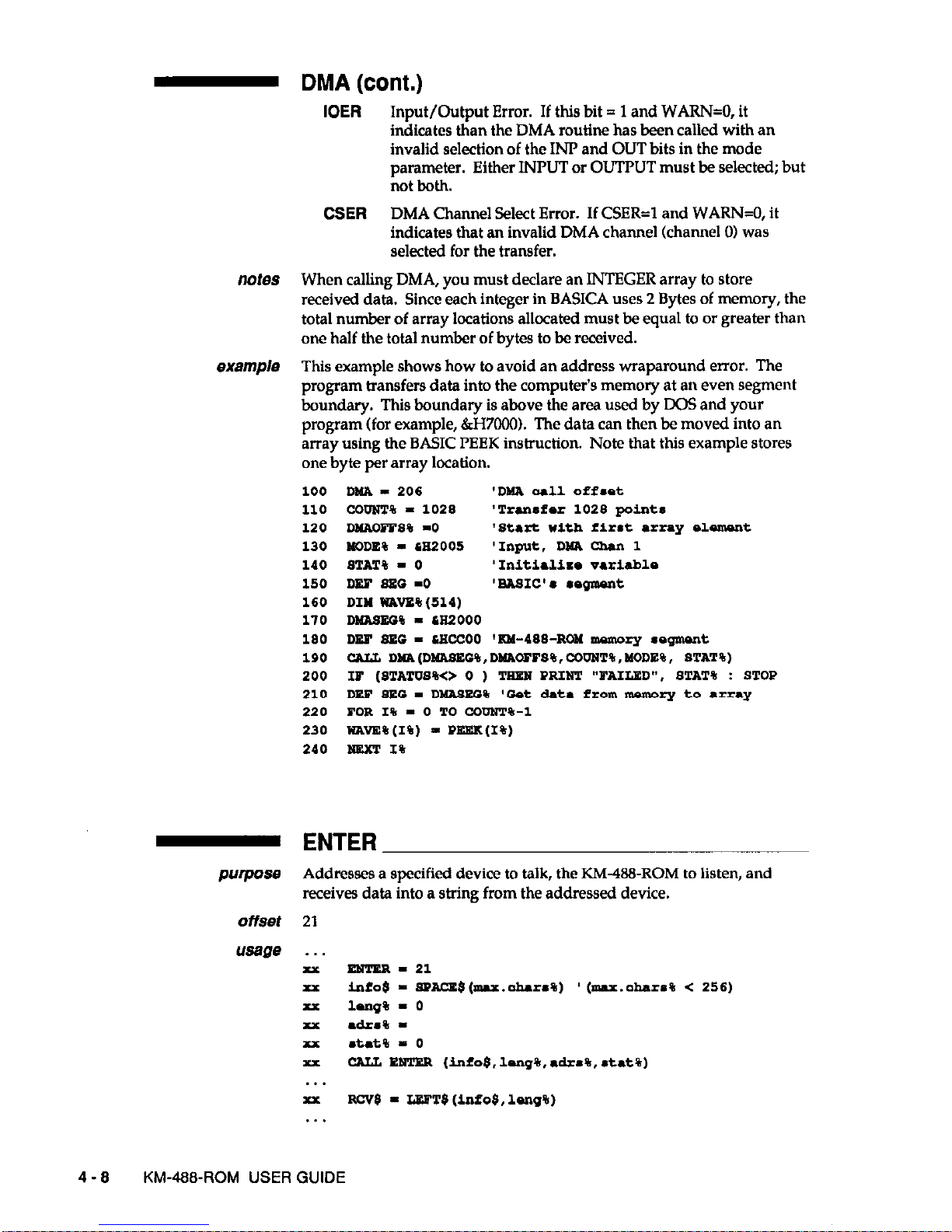
- DMA (cont.)
IOER
Input/Output Error. If this bit = 1 and WARN=O, it
indicates than the DMA routine has been called with an
invalid selection of the INP and OUT bits in
the
mode
parameter. Either INPUT or OUTPUT must be selected; but
not both.
CSER
DMA Channel Select Error. If CSER=l and WAR&O, it
indicates that an invalid DMA channel (channel 01 was
selected for the transfer.
notes When calling DMA, you must declare an INTEGER array to store
received data. Since each integer in BASICA uses 2 Bytes of memory, the
total number of array locations allocated must be equal to or greater than
one half the total number of bytes to be received.
exa!trp/e This example shows how to avoid an address wraparound error. The
program transfers data into the computer’s memory at an even segment
boundary. This boundary is above the area used by DOS and your
program (for example, &H70001. The data can then be moved into an
array using the BASIC PEEK instruction. Note that this example stores
one byte per array location.
100
110
120
130
140
150
160
170
180
190
200
210
220
230
240
DYA - 206
'DMA or11 Off.&
ccQuT% - 1028 'Trane?ar 1026 points
DuAcPPS% -0
'St.rt with first array slomont
NODE% - 6E2005 'Input. DM% Ghan 1
STAT% - 0 'Initialira variabls
DEF es5 -0
‘w&SIC’. l sgmant
DIM WAVE%(tll)
DMASEC% - CR2000
DEF SEC - CECCOO 'KM-488~Roll memory segment
CAI& D~(DHASED$,DIIAOFBX%,CDDNT%,MODE%, STAT%)
IP (STATUS%<> 0 ) TEES PRIUT "FAILED", STAT% :
STOP
DEP 8EG - D-EC% 'Cat data
from
manwry to .rn.y
POR
1%
- 0 TO CODXT%-1
wAvE%(I%)
- PEEK(I%)
tam
1%
- ENTER
purpose Addresses a specified device to talk, the KM-488-ROM to listen, and
receives data into a string from the addressed device.
offset 21
. .
xx ENTER-21
xx
infob - SPACE$(mru.ah.rs%) '(max.ohara% < 256)
xx lurg% - 0
P drS% xx mtat% - 0
xx CArL liwJ!ER (info8,lang%,akm%,
et&,%)
. . .
xx RCV$ -
LIWTB
(info$,
lsnq%)
. . .
4-8 KM-488~ROM USER GUIDE
Page 49

- ENTER (cont.)
pafameters Mo$ is a STRING (up to 256 characters) which is to hold the received
data. The string must be long enough to receive the expected number of
characters. Carriage returns and the message terminator character in the
incoming data are ignored and not stored with the received data. You
should use the BASIC SPACF$ function to declare a string which is long
enough to store the expected maximum number of characters to be
received. After the data has been received, it should be copied into a
new string which has been “trimmed” to length with the BASIC LEm$
function. Or else, you may trim the first string to length, provided that
you resize it with the BASIC SPACE$ function prior to calling the
ENTER function again.
a&s% is an INTEGER containing the IEEE bus address of the device
that will sent the data and the terminator to be used. This byte is of the
following format:
Adrs (Input Parameter) - Low Byte
BIT 7
6 5
4
3
2
1
0
TRMl TRMO 0
ADR4 ADR3 ADR2
ADRl
ADRO
Where
TRMl-0
Terminator Select. These two bits select the Message
Terminator to be used to signal the end of a transmission.
Available terminator selections are
TRMl TRMO TERMINATOR # DEFAULT
0 0 0 LF
0 1 1
CR
1 0
2
1 1
3
These terminators are defined upon system configuration
and are stored
(along
with the BASICA library code) in the
EEPROM. They can be changed by running the CONF’IG
program as described in Chapter 2.
The easiest way to specify an alternate terminator is to add
a factor to the GPIB address of the desired instrument
which is specified within the ENTER call. The factors
added for each terminator are as follows:
GPIB Address + 0 = Terminator 0
GPIB Address + 64 = Terminator 1
GPIB Address + 128
= Terminator 2
GPIB Address + 192
= Terminator 3
For example, if you wanted to receive a message using
terminator 2 from a device at GPIB address 10, the value of
adrs% supplied to ENTER would be 138 decimal (10 + 128).
ADR4-0
GPIB Address. These five bits are used to represent the
GPIB address of the device to which the data is to be sent.
GPIB addresses can range from 0 to 30.
PROGRAMMING IN BASICA OR GWBASIC
4 - 9
Page 50
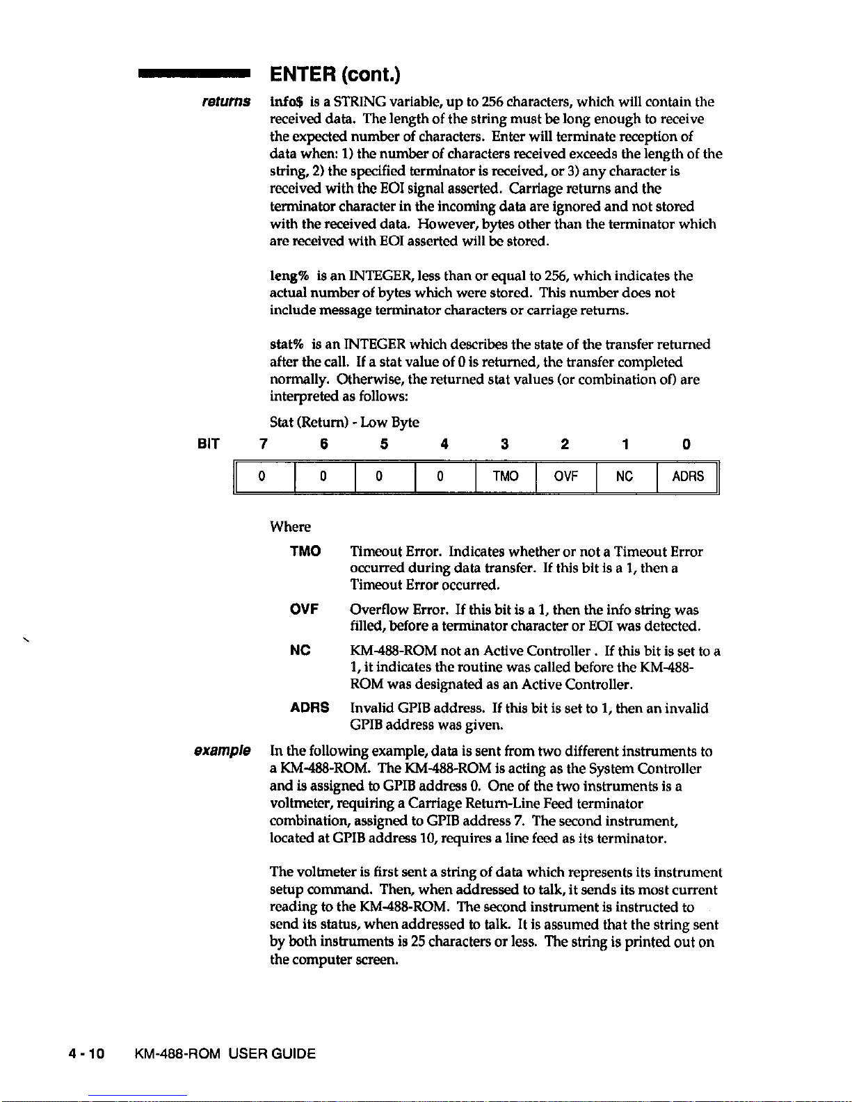
- ENTER (cont.)
fetumS info$ is a STRING variable, up to 256 characters, which will contain the
received data. The length of the string must be long enough to receive
the expected number of characters. Enter will terminate reception of
data when: 1) the number of characters received exceeds the length of the
string, 2) the specified terminator is received, or 3) any character is
received with the
EOI
signal asserted. Carriage returns and the
terminator character in the incoming data are ignored and not stored
with the received data. However, bytes other than the terminator which
are received with EOI asserted will be stored.
leng% is an INTEGER, less than or equal to 256, which indicates the
actual number of bytes which were stored. This number does not
include message terminator characters or carriage returns.
stat% is an INTEGER which describes the state of the transfer returned
after the call. If a stat value of 0 is returned, the transfer completed
normally. Otherwise, the returned stat values (or combination of) are
interpreted as follows:
Stat (Return) -Low Byte
BIT 7
6
5
4
3
2
1 0
0 0
0 0
TM0 OVF NC
ADRS
Where
TM0 Timeout Error. Indicates whether or not a Timeout Error
occurred during data transfer. If this bit is a 1, then a
Timeout Error occurred.
OVF
Overflow Error. If this bit is a 1, then the info string was
filled, before a terminator character or EOI was detected.
NC
KM-468-ROM not an Active Controller . If this bit is set to a
1, it indicates the routine was called before the KM-488ROM was designated as an Active Controller.
ADRS
Invalid GPIB address. If this bit is set to 1, then an invalid
GPIB address was given.
example In the following example, data is sent from two different instruments to
a KM-l&ROM. The KM-488-ROM is acting as the System Controller
and is assigned to GPIB address 0. One of the two instruments is a
voltmeter, requiring a Carriage Rehnn-Line Feed terminator
combination, assigned to GPIB address 7. The second instrument,
located at GPIB address 10, requires a line feed as its terminator.
The voltmeter is first sent a string of data which represents its instrument
setup command. Then, when addressed to talk, it sends its most current
reading to the KM-&J-ROM. The second instrument is instructed to
send its status, when addressed to talk. It is assumed that the string sent
by both instruments is 25 characters or less. The string is printed out on
the computer screen.
4-10
KM-488~ROM USER GUIDE
Page 51

10
20
so
31
32
34
36
40
4s
so
60
70
SO
90
100
110
120
I.30
140
150
160
170
172
180
190
200
210
220
230
2‘0
250
260
270
- INIT
purpose Initializes a KM438-ROM by assigning it a GPIB address and
establishing it as a System Controller or Device.
offset 0
usage . . .
P
IUIT - 0
xx a&*%- : mode%P 0AI.L IWIT(a&a%,modo%)
. . .
PSrS!rkVSrS adrs% is an INTEGER representing the IEEE bus address of the KM-488-
ROM. This is an integer from 0 to 30.
PROGRAMMING IN BASICA OR GWBASIC
4-11
Page 52

- INIT (cont.)
mode% is an INTEGER representing the operating mode of the KM-488ROM. These can be any of the following values:
Mode-Low Byte
BIT 7
6
6 4
3
2
1
0
X X
X X X
FAST DEV X
Where
X May be any value.
FAST
Handshake Speed. If this bit is set to 1, High Speed GPIB
bus handshaking will be usedQOOns.). If it is set to 0, Low
Speed GPIB bus handshaking (2 s.) will be used. See
Chapter 3 for more information regarding the handshake
speed.
DEV Device. If this bit is set to 1, then the KM-488-ROM is acting
as a Device. Otherwise, when this bit is set to 0, the KM488ROM is acting as a System Controller. When System
Controller is selected, the GLIB IFC line is momentarily
asserted.
refurfls None.
example This example initializes the KM-488-ROM as a System
Controller
with a
IEEE address of 0 with a High Speed Handshake.
10
DNF sEc-sEccoo
20 INIT=
30 AoNa%-o : NOON% -4
10
CALL INIT (Z&INS%, NODE%)
- PPOLL
PvP-e
Initiates a Parallel Poll and returns a parallel poll response byte.
NOTE: Many GPIB devices do not support parallel polling. Check your
device’s documentation.
offset 15
usage . . .
xx PPOIZ - 15
xx rs*p% - 0
xx PPOLL(rs~p%)
. .
parameters None.
returns resp% is an INTEGER which will contain the parallel poll response.
4-12
KM-488sROM USER GUIDE
Page 53

- PPOL (cont.)
notes Before you call the PPOLL routine, you must configure the Parallel Poll
response of the device. To do this,
l
Address it to listen.
l
Send it a GI’IB Parallel Poll Configure (PPC) command, using the
XMIT command.
l
Send a Parallel Poll Enable byte using the KM488-ROM XMIT
command. (Use the mnemonic CMD followed by nnn where nnn is the
decimal value of the Parallel Poll Enable byte.
The Parallel Poll Enable Byte is of the format OllOSPPP, where
S is the parallel poll response value (0 or 1) that the device
uses to respond to the parallel poll when service is required.
PPP is a 3-bit value that tells the device being configured
which data bit it should use as its parallel poll response
CD101 through DIOB).
example This example assumes that the KM-488-ROM is connected to a Sorenson
HPD3010 Power Supply. This device is located at GI’IB address 1. It is
also assumed that this device drives bit 3 of the Parallel Poll Response
byte to a logic “1” when service is required. To program the device to
respond properly, send the Parallel Poll enable byte 01101011 (107) via
the XMIT command.
- RCV
purpose Receives data into a string.
offset
usage
6
. . .
xx Ncv-6
P info+ sPAce$(mu.oharm%) '(mar.ohar.s% < 256)
xx hog%=
xx
.t.t% -
xx CALL Rev (info$,leng%,*tat%)
. . .
NOTE: The alternate usage assumes the use of Input Message
Terminator 0.
PROGRAMMING IN BASICA OR GWBASIC
4-13
Page 54

- RCV (cont.)
paramefers Mo$ is a STRING (256 characters max.) which will hold the received
data. The string must be long enough to receive the expected number of
characters. Carriage returns and the message terminator character in the
incoming data are ignored and not placed in received data. However,
bytes other than the terminator received with EOI will be stored. You
should use the BASIC SPACE$ function to declare a string which is long
enough to store the expected maximum number of characters to be
received. After the data has been received, it should be copied into a
new string and “trimmed” to length with the BASIC LEm$ function.
NOTE Before calling RCV, stat% must be initialized for terminator
selection.
stat% is an INTEGER that selects the input terminator to be used. ‘Ike
terminator (stat%) values follow:
Stat (Input) - Low Byte
BIT 7
6
5 4 3 2
1 0
TRMl TRMO X
X X X
X X
11
Where
X
May be any value.
TRMl-0 Terminator Select. These two bits select the Input Message
Terminator to be used to signal the end of a transmission.
Available terminator selections are
TRMl TRMO
TERMINATOR #
DEFAULT
:
0
0
LF
1 1
CR
1 0
2
1
1
3
These terminators are defined upon system configuration
and are stored (along with the BASICA library code) in the
EEPROM. To change their values, run the CONFIG
program as described in Chapter 2.
info$ is a STRING variable (256 characters max.) containing the received
data. The string must be long enough to receive the expected number of
characters. Enter will terminate reception of data when 1) the number of
characters received exceeds the length of the string, 2) a message
terminator is received, or 3) any character is received with the EOI signal
asserted. Carriage returns and the message terminator in the incoming
data are ignored and not placed in received data. However, bytes other
than the message terminator received with EOI are stored.
leng% is an INTEGER, less than or equal to 256, which indicates the
actual number of bytes which were received and stored.
stat% is an INTEGER which describes the state of the transfer returned
after the call. The returned stat% values (or combination of) are
interpreted as follows:
4-14 KM-488-ROM USER GUIDE
Page 55
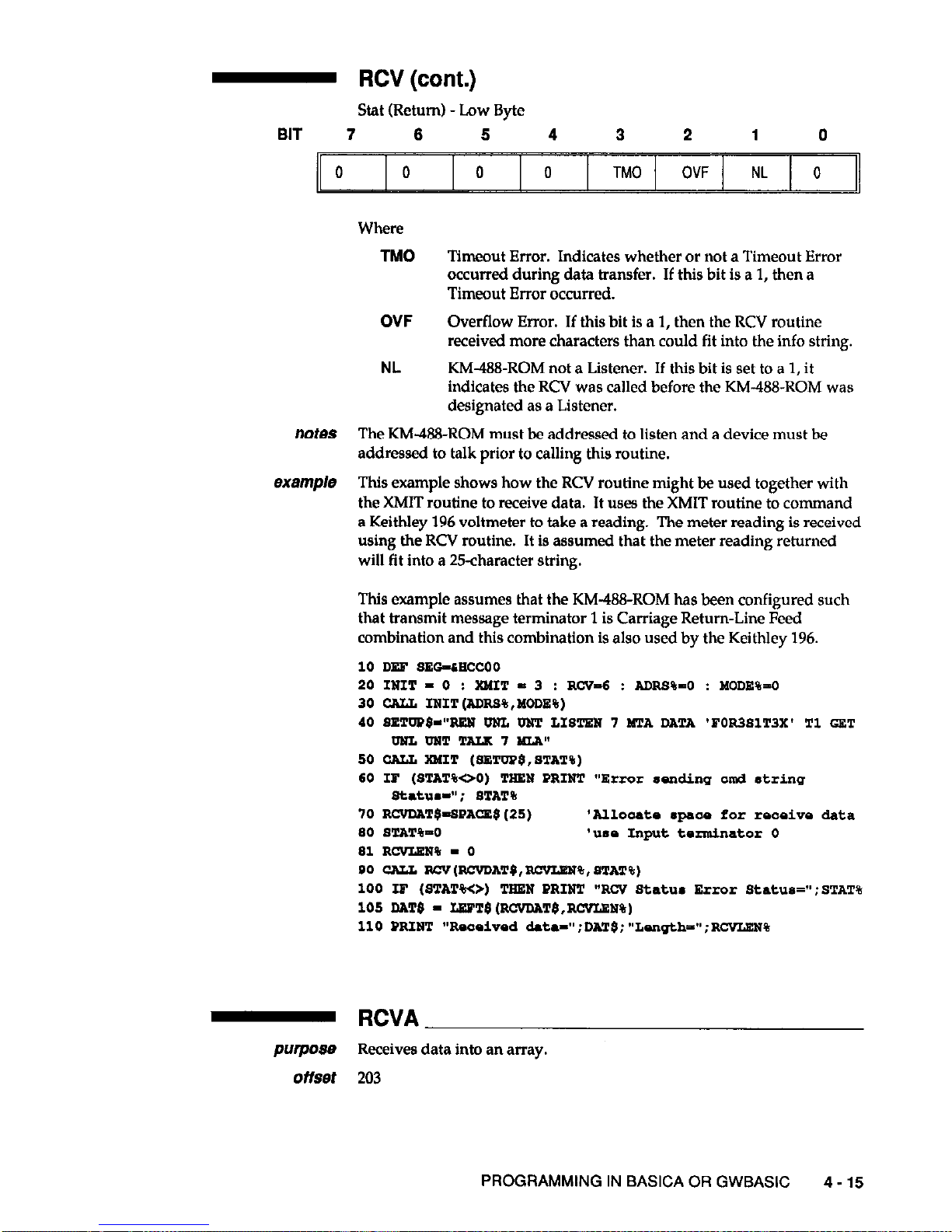
- RCV (cont.)
Stat (Return) - Low Byte
BIT 7
6 6 4
3 2 1
0
0
0 0 0
TM0 OVF NL
0
Where
TM0
Timeout Error. Indicates whether or not a Timeout Error
occurred during data transfer. If this bit is a 1, then a
Timeout Error occurred.
OVF
NL
Overflow Error. If this bit is a 1, then the RCV routine
received more characters than could fit into the info string.
KM488-ROM not a Listener. If this bit is set to a 1, it
indicates the RCV was called before the KM-488-ROM was
designated as a Listener.
note9
The KM4?8-ROM must be addressed to listen and a device must be
addressed to talk prior to calling this routine.
ex&?f1@8 This example shows how the RCV routine might be used together with
the XMIT routine to receive data. It uses the XMIT routine to command
a Keithley 196 voltmeter to take a reading. The meter reading is received
using the RCV routine. It is assumed that the meter reading retomed
will fit into a 25-character string.
This example assumes that the KM-488-ROM has been configured such
that transmit message terminator 1 is Carriage Return-Line Feed
combination and this combination is also used by the Keithley 196.
10 DEF SEG-CSCCOO
20 IUIT - 0 : WIT - 3
: RCV-6 : ADRS%-0 : MODE%=0
30 CALL IWIT(ADRS%,MODE%)
40 SETDPWTtEN DNI, DNT
IJSTE~
7 MTA DATA 'POR381T3X' Tl GET
UULIMTTAIX7MLP."
50 CALL XMIT (9ETOP$,STAT%)
60 IP (STAT%OO) THEN PRINT
“Error
sading and &ring
9tatua-";
STAT%
70 RCVDAT$=SPAcE$(25)
'Allooato *paae for roooivo data
SO
STAT%-0
'USS Input terminator 0
81 RcvLEW% - 0
90 CALL RCV(RCVDAT$, -%, STAT%)
100 LF
(STAT%<>)
TEEU PRINT "RCV Status
Error
Status=":STAT%
105 DA!l'$ - IJWT~(RCVDAT$,RCVLEN%)
110 PRINT "Reosivad &t~-":DAT$:"LMcJthi";RCVLEN%
- RCVA
purpose Receives data into an array.
offset 203
PROGRAMMING IN BASICA OR GWBASIC 4-15
Page 56

- RCVA (cont.)
usage
. . .
P EVA-203
xx DIY ISmDAT%(N%)
xx
l g% -
P ofa% -
P mmxlsn% - 2*u%
P lavlM% xx
atat% -
xx
ofa%-VARVTR(indat%(O))
P CALL RCVA(~sg%,of~%,murlon%,mvllsn%,~tat%)
alternate usage
~Y(~eg%,of~%,nurlsn%,ro"lsn%,‘t*t%)
NOTE: The alterante usage assumes the use of Input Message
Terminator 0.
parmefers
seg% is an integer representing the segment portion of the memory
address of the data. seg% is usually set to -1 to indicate the BASICA data
segment.
ofs% is the offset portion of the memory address of the data. This is
usually obtained using the VARPTR function. The VAWTR function
must be called immediately prior to the RCVA function call and all
variables used within the program must be declared prior to the
VARPTR function. This is because BASICA dynamically allocates
storage space and if variables are declared after the VARPTR call, the
array may be relocated and the data will be placed into the wrong
location. This may result in a program crash.
maxlen% is an INTEGER containing the maximum number of data
bytes to be received. See Programming Note 4, found at the beginning of
this section, if you want to send more than 32767 bytes.
stat% is an INTEGER which selects the type of terminator to be used.
This parameter must be initialized every time you call the RCVA routine.
This integer is interpreted according to the following format:
Stat (Input Parameter) - Low Byte
BIT 7
6
5 4
3
2 1 0
STRM TRMl
TRMO X
X
X X
X
Where
STRM
Enable/Disable String Message Terminators. If this bit is 1,
a Message Terminator Character will be used to detect the
end of reception. If this bit is 0, a Message Terminator
Character will not be used.
TRMl-0 Terminator Select. These two bits select the Input Message
Terminator to be used to signal the end of a transmission.
(The STRM bit must be set to 1.1 Available terminator
selections are
4-16
KM-488~ROM USER GUIDE
Page 57

- RCVA
(cont.)
TRMl TRMO TERMINATOR # DEFAULT
0 0
0 LF
0 i
:. CR
1
1 1
3
The values for these terminators can be changed by running
the CONFIG program as described in Chapter 2.
returns rcvlen% is an INTEGER containing the actual number of data bytes
which were received.
stat%
is an INTEGER describing the state of the transfer returned after
the call.
The RCVA routine returns three status bits within the STAT variable.
The TM0 bit is used to signal a timeout error. The REOI bit signals that
the routine returned because the terminator was detected (if enabled), or
EOI was received. The NL bit is set if the RCVA routine was called and
the board was not addressed to listen. Unlike other KM-488-ROM
routines, it is possible to return a non-zero status when the call was
completed successfully.
Stat (Return) -Low Byte
BIT 7
6 5
4
3
2 1
0
0
0 REOi
0 TM0
0 NL 0
REOI Reason for RCVA Termination. If this bit is a 1, then RCVA
routine ceased because an EOI or terminator character was
received. If this bit is a 0, then the RCVA was terminated
because an error occurred or the maximum byte count was
reached.
TM0
Timeout Error. Indicates whether or not a Timeout Error
occurred during data transfer. If this bit is a 1, then a
Timeout Error occurred.
NL KM-488-ROM not a Listener. If this bit is set to a 1, it
indicates the RCVA was called before the KM-488-ROM
was designated as a Listener.
1. The KM-488ROM must be addressed to listen before calling this
routine.
2. When calling RCVA, you must declare an integer array to store
received data. Since each integer in BASICA uses 2 bytes of memory, the
total number of array locations allocated must be equal to or greater than
one half the total number of bytes to be received.
3. The maxlen% parameter must not exceed twice the number of array
locations or else the data will be stored into an area of memory which
has been allocated to different parts of the system.
PROGRAMMING IN BASICA OR GWBASIC 4-17
Page 58
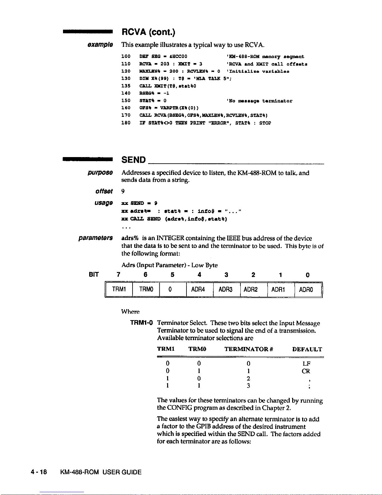
- RCVA (cont.)
This example illustrates a typical way to use RCVA.
Purpose
offset
usage
parameters
SEND
Addresses a specified device to listen, the KM-488-ROM to talk, and
sends data from a string.
9
XXSEUD - a
xx. a&*%=
: stat% - : info5 - 1). , .”
x.x CALL BEaD (drs%,info$,*t*t%)
. . .
adrs% is an INTEGER containing the IEEE bus address of the device
that the data is to be sent to and the terminator to be used. This byte is of
the following format:
Adrs (Input Parameter) - Low Byte
BIT 7 6
5 4 3 2
1
0
TRMl
TRMO 0
ADR4
ADF13 ADR2 ADRl ADRO
Where
TRMl-0 Terminator Select. These two bits select the Input Message
Terminator to be used to signal the end of a transmission.
Available terminator selections are
TRMl
TRMO TERMINATOR #
DEFAULT
0 0 0
0 1 1 ii
1
0
2
1 1
3
The values for these terminators can be changed by running
the CONFIG program as described in Chapter 2.
The easiest way to specify an alternate terminator is to add
a factor to the GPIB address of the desired instrument
which is specified within the SEND call. The factors added
for each terminator are as follows:
4-16 KM-466~ROM USER GUIDE
Page 59
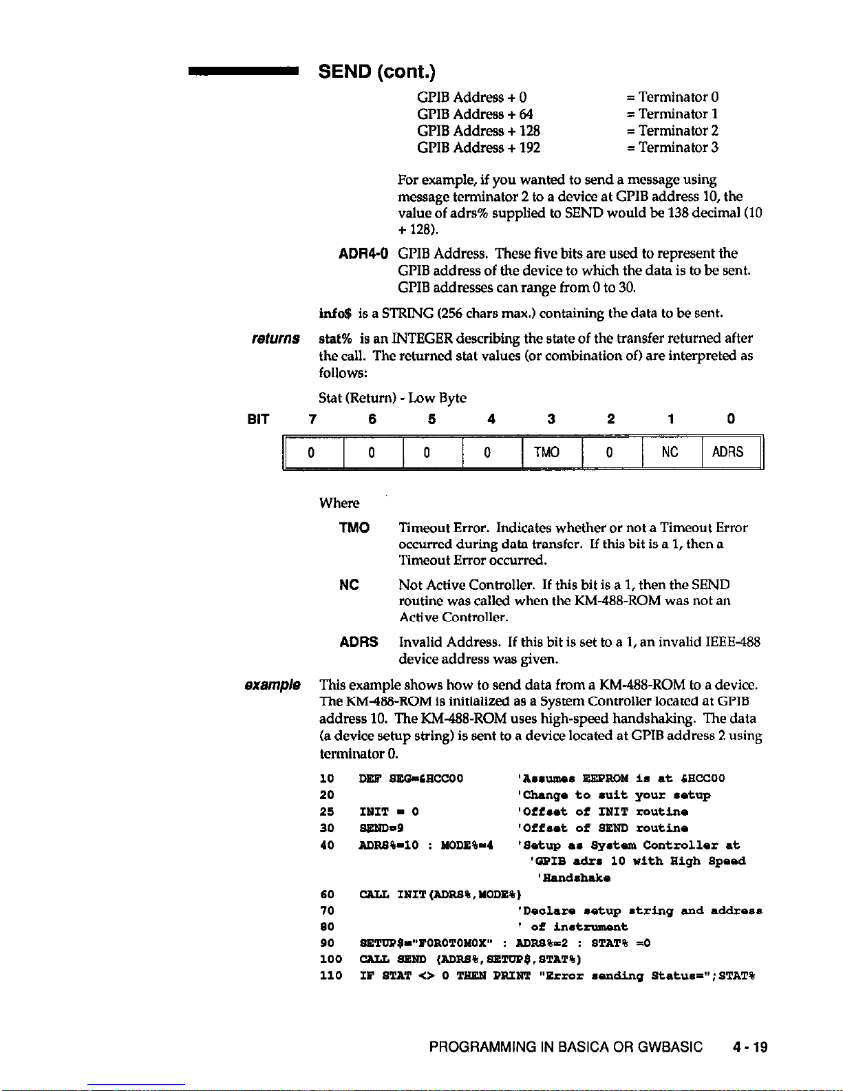
- SEND (cont.)
GPIB Address + 0
= Terminator 0
GPIB Address + 64
= Terminator 1
GPIB Address + 128
= Terminator 2
GPIB Address + 192
= Terminator 3
For example, if you wanted to send a message using
message terminator 2 to a device at GPIB address 10, the
value of adrs% supplied to SEND would be 138 decimal (10
+ 128).
ADRGO
GPIB Address. These five bits are used to represent the
GLIB address of the device to which the data is to be sent.
GLIB addresses can range from 0 to 30.
Info$ is a STRING (256 chars max.) containing the data to be sent.
returns stat% is an INTEGER describing the state of the transfer returned after
the call. The returned stat values (or combination of) are interpreted as
follows:
Stat (Return) -Low Byte
BIT 7 6 5
4
3
2 1 0
0 0 0 0 TM0 0
NC
ADRS
Where
TM0
Timeout Error. Indicates whether or not a Timeout Error
occurred during data transfer. If this bit is a 1, then a
Timeout Error occurred.
NC Not Active Controller. If this bit is a 1, then the SEND
routine was called when the KM-488-ROM was not an
Active Controller.
ADRS
Invalid Address. If this bit is set to a 1, an invalid IEEE-488
device address was given.
examp/e This example shows how to send data from a KM-488-ROM to a device.
The KM4?8-ROM is initialized as a System Controller located at GLIB
address 10. The KM488-ROM uses high-speed handshaking. The data
(a device setup string) is sent to a device located at GPIB address 2 using
terminator 0.
10
DES" SEG-LECCOO
‘Assumes
NNPROM is at CHCCOO
20 'change to suit
your l
etup
25 INIT - 0 'Offset
of INIT
routinn
30 9NNDn9
'Offast
of
SEND routine
40 Arms%-10 : MclnE%-4
‘a&up a‘ ay&xm
Controllsr at
'GPIB
adrs 10 with High Spsod
'kkndshaks
60 CALL INIT (ADl=,S% , XODE%)
70 'Dsalars .&up string and addroes
80 1
of
instrument
90 SNTDP$-~~POROTOMOX" : AD=%=2 : *TAT% -0
100 CAI& SSND
(ADBS%,SET(IP$.BTAT%)
110 IP STAT <> 0 TEEN PRINT "Error sonding Status=";STAT%
PROGRAMMING IN BASICA OR GWBASIC 4-19
Page 60

- SETINT
putpose Sets the m-488-ROM’s interrupt enable bits.
offset
212
usage . . .
P
8ETINT - 212
xx intvrl% P
CALL SETINT(izitval%)
. .
parameters IntvaI% is an INTEGER containing the address and value of the
Interrupt Mask Register. This is interpreted as follows:
INTVAL (Input) -High Byte
BIT 7
6 5 4 3 2 1 0
X X X X
X X X ADRS
Where
X May be any value.
ADRS If this bit is set to 0, bits 0 through 7 will be written to
Interrupt Mask 1. If this bit is set to 1, bits 0 through 7 will
be written to Interrupt Mask 2.
INTBRRUFF MASK 1
INTVAL (Input) -Low Byte (ADRS = 0)
BIT 7
6 5 4 3 2 1 0
0 0 GET 0 DEC 0 0 0
Where
GET
DEC
When this bit is set to 1, an interrupt will be generated
when a KM-488-ROM acting as a device received a GPIB
GET (Group Execute Trigger) command while addressed to
listen.
When this bit is set to 1, an interrupt is generated when a
Device Clear is received.
INTERRUPT MASK 2
INTVAL (Input) -Low Byte (ADRS = 1)
BIT 7 6 5 4 3 2 1 0
0 SRQI 0 0 0 LOKC REMC ADSC
SRQI When this bit is set to 1, an interrupt is generated when
SRQ is received.
LOKC
When this bit is set to 1, an interrupt is generated when the
state of the Local Lockout bit changes.
4-20 KM-488-ROM USER GUIDE
Page 61

returns
notes
examp/e
wwse
offset
usage
parameters
SETINT (cont.)
REMC When this bit is set to 1, an interrupt is generated when the
state of the Local/Remote bit changes.
ADSC
When this bit is set to 1, an interrupt is generated when the
state of the LA, TA, or CIC bits within the address status
register changes.
None.
You must have an interrupt handling routine set-up in order to use the
interrupts. In BASICA, the most common way to handle interrupts is
through a routine which maps the interrupt into BASICA’s lightpen
interrupt,
allowing
you to execute a BASICA ON PEN statement to
execute the interrupt service routine.
This example shows you how to use the SETINT routine to enable the
SRQ interrupt.
10
DER SE0 - 4HCCOO
20 SSTIST - 212
30 IuTvAL% - itI
40 CALL WTIUT (IUTVAL~) ‘Enable SRQ
intarrupt
SETSPOLL
Defines the Serial Poll Response of a KM-488-ROM acting as a device
(non-Controller).
215
xx SETWOLL - 215
P n.p* xx CALT
SETSPOIL
(reap%)
resp%
is an INTEGER describing the serial poll response and the state of
the SRQ bit. This byte is of the following format:
Resp% (Input) - Low Byte
BIT 7
6 6
4
3
2
1 0
SPRS RSV SPR6 SPR5 SPR4 SPR3 SPRZ SPRl
Where
SPRl-6
Bits 1 through 8 of this device’s Serial Poll Response Byte.
RSV
If this bit is 1, SRQ will be asserted to request servicing.
Otherwise, SRQ
will not be asserted.
returns
None.
PROGRAMMING IN BASICA OR GWBASIC
4-21
Page 62
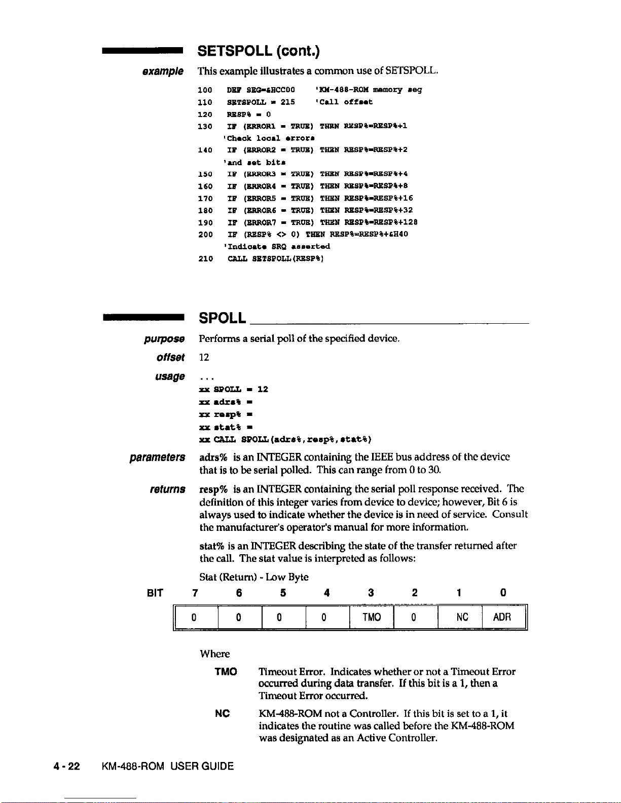
- SETSPOLL (cont.)
This example illustrates a common use of SETSPOLL.
- SPOLL
purpose
Performs a serial poll of the specified device.
offset 12
usage
. . .
XXWOLL-12
xx. a&a% -
xx rsspe -
xx
&Gate
=
xx CrLLL WOLL (adz*%, rsape, *tat%)
parameters
adrs% is an INTEGER containing the IEEE bus address of the device
that is to be serial polled. This can range from 0 to 30.
returns
resp% is an INTEGER containing the serial poll response received. The
definition of this integer varies from device to device; however, Bit 6 is
always used to indicate whether the device is in need of service. Consult
the manufacturer’s operator’s manual for more information.
stat% is an INTEGER describing the state of the transfer returned after
the call. The stat value is interpreted as follows:
Stat (Return) -Low Byte
BIT 7
6
6 4
3
2 1 0
0 0 0 0 TM0 0 NC ADR
Where
TM0
Timeout Error. Indicates whether or not a Timeout Error
occurred during data transfer. If this bit is a 1, then a
Timeout Error occurred.
NC
KM48-ROM not a Controller. If this bit is set to a 1, it
indicates the routine was called before the KM-488-ROM
was designated as an Active Controller.
4-22 KM-466~ROM USER GUIDE
Page 63
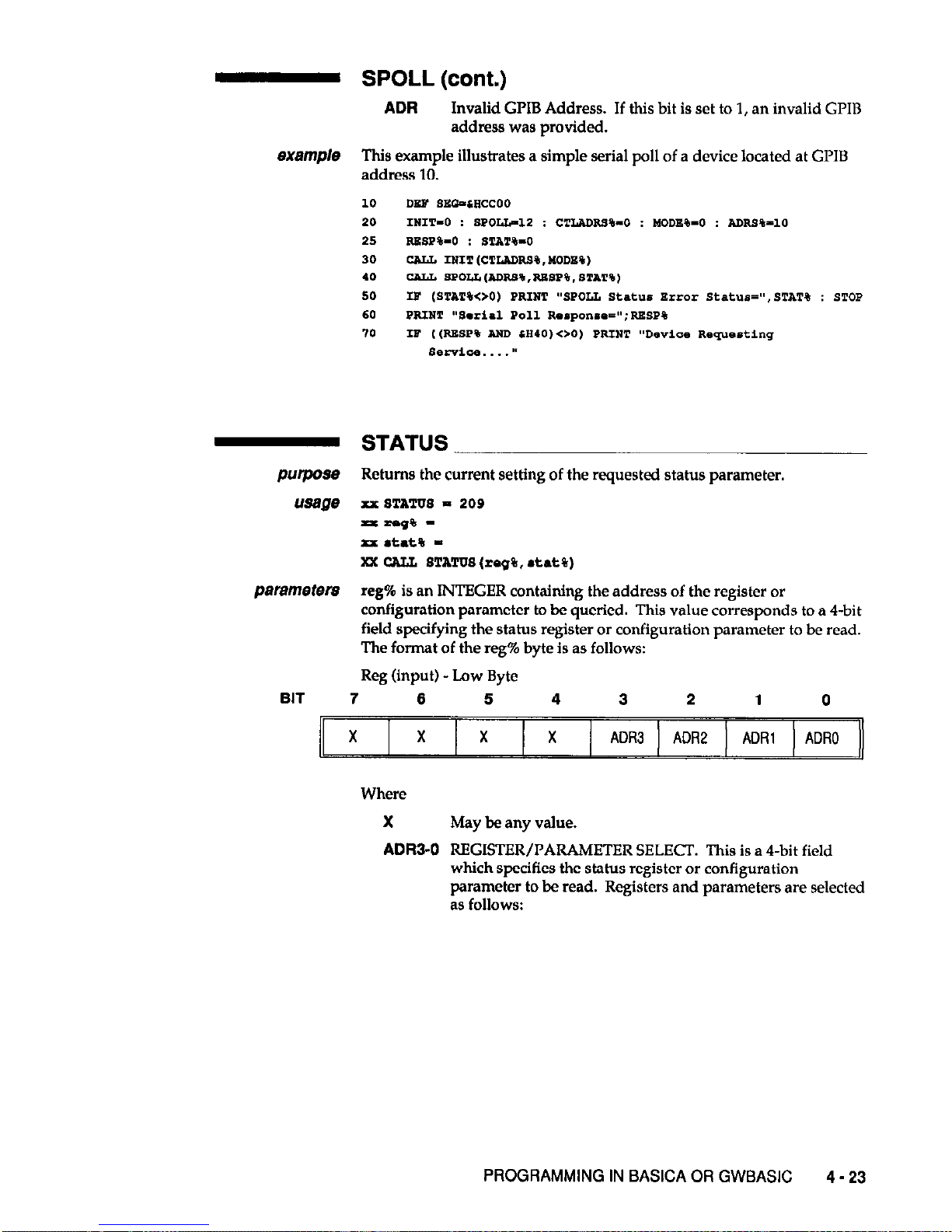
example
SPOLL (cont.)
ADR
Invalid GPIB Address. If this bit is set to 1, an invalid GLIB
address was provided.
This example illustrates a simple serial poll of a device located at GLIB
address 10.
10
20
25
30
10
SO
60
70
im-
usage
parameters
BIT 7
6 6 4
3 2 1
0
X
X
X X
ADR3
ADR2 ADRl
ADRO
STATUS
Returns the current setting of the requested status parameter.
xx
STATUS - 209
xxrrlJ% xx *tat% Xx CALL
STATUS
(rag%, &at%)
reg% is an INTEGER containing the address of the register or
configuration parameter to be queried. This value corresponds to a 4-bit
field specifying the status register or configuration parameter to be read.
The format of the reg% byte is as follows:
Reg (input) - Low Byte
X
May be any value.
ADR3-0
REGISTER/PARAMETER SELECT. This is a 4.bit field
which specifies the status register or configuration
parameter to be read. Registers and parameters are selected
as follows:
PROGRAMMING IN BASICA OR GWBASIC
4 - 23
Page 64
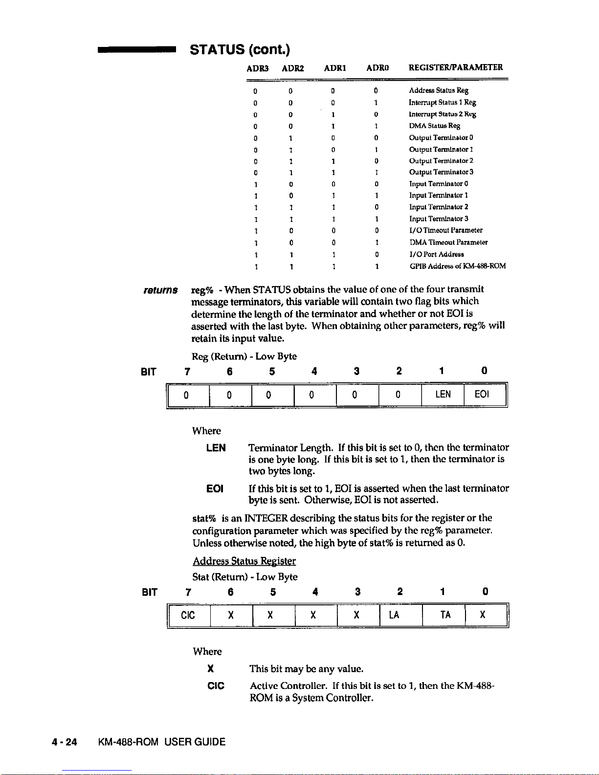
STATUS (cont.)
ADR3
ADRZ
ADRl
ADRO
REGISTER/PARAMETER
0 0 0
0 Addregs statu8 Re*
0 0 0
1 htemlpl status 1 Reg
0 0 1
0 InterNpI statw 2 aeg
0 0 *
1 DMA StalusReg
0 1 0
0 output Tdstor 0
0 1 0
1 output TermlnatM 1
0 1 1
0 output Temunator 2
0 1 1
1 output Terminstor 3
1 0 0
0 Input Terminator 0
I 0 *
1 Jnput Terminator 1
1 1 1
0 Input Terminator 2
1 1 1
1 Input Terminator 3
1 0 0
0 I/O nmeo”t Parameter
1 0 0
1 DMA Timeo”t Parameter
1 1 1
0 I/O Port Address
1 1 1
1 GPIB Address of KM488-ROM
returns reg% -When STATUS obtains the value of one of the four transmit
message terminators, this variable will contain two flag bits which
detetine the length of the terminator and whether or not EOI is
asserted with the last byte. When obtaining other parameters, reg% will
retain its input value.
Reg (Return) -Low Byte
BIT
7 6 5 4
3 2 1 0
0 0 0 0 0
0 LEN EOI
Where
LEN
Terminator Length. If this bit is set to 0, then the terminator
is one byte long. If this bit is set to 1, then the terminator is
two bytes long.
EOI
If this bit is set to 1, EOI is asserted when the last terminator
byte is sent. Otherwise, EOI is not asserted.
stat% is an INTEGER describing the status bits for the register or the
configuration parameter which was specified by the reg% parameter.
Unless otherwise noted, the high byte of stat% is returned as 0.
Address Status Reek&
Stat (Return) -Low Byte
BIT 7
6 5
4
3
2 1 0
cc
X X
X
x LA TA X
Where
X This bit may be any value.
CIC
Active Controller. If this bit is set to 1, then the KM48&
ROM is a System Controller.
4-24 KM-488~ROM USER GUIDE
Page 65

- STATUS (cont.)
LA
Listener. If this bit is set to 1, then the KM&?&ROM is a
Listener.
TA
Talker. If this bit is set to 1, then the KM488-ROM is a
Talker.
Interrout Status Reeister 1
Stat (Return) -Low Byte
BIT 7
6 5
4 3
2 1
0
X X
GET X
DEC
X X
X
Where
X
This bit may be any value.
GET
Group Execute Trigger. If this bit is set to 1, then a Group
Execute Trigger command was received while the KM488-
ROM was a device.
DEC
When this bit is set to 1, a Device Clear was received.
Interruvt Status Reeister 2
Stat (Return) -Low Byte
BIT 7
6
5
4 3
2 1 0
X SRQl LOK
REM
X X X ADSC
Where
X This bit may be any value.
SRQI
When this bit is set to 1, it indicates SRQ was active. (Active
Controller mode only.)
LOK
When this bit is set to 1, the device was set to Local Lockout.
(Device mode only.)
AEMC
When this bit is set to 1, the device was configured for
remote operation. (Device mode only.)
ADSC
When this bit is set to 1, a change of the address status
occurred (i.e., untalk to talk, device to active controller, etc.).
DMA Status Reeister
Stat (Return) - Low Byte
BIT 7
6
5 4 3
2 1 0
X X
X X
TC3
TC2 TCl X
NOTE: DMA Status Register: it is useful to check the status
of this register when running DMA operations in
background mode.
Where
X
This bit may be any value.
PROGRAMMING IN BASICA OR GWBASIC
4-25
Page 66
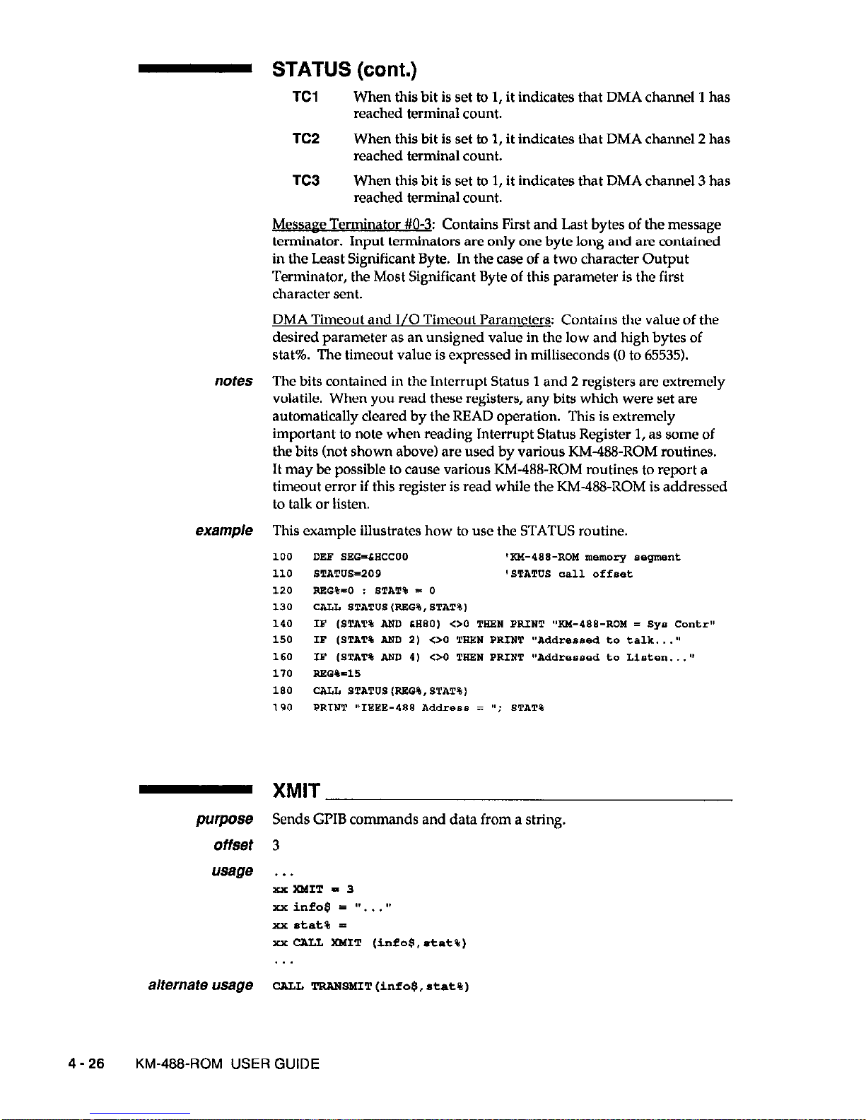
- STATUS (cont.)
TCl
When this bit is set to 1, it indicates that DMA channel 1 has
reached terminal count.
TC2
When this bit is set to 1, it indicates that DMA channel 2 has
reached terminal count.
TC3
When this bit is set to 1, it indicates that DMA channel 3 has
reached terminal count.
Message Terminator #O-3: Contains First and Last bytes of the message
terminator. Input terminators are only one byte long and are contained
in the Least Significant Byte. In the case of a two character Output
Terminator, the Most Significant Byte of this parameter is the first
character sent.
DMA Timeout and I/O Timeout Parameters: Contains the value of the
desired parameter as an unsigned value in the low and high bytes of
stat%. The timeout value is expressed in milliseconds (0 to 65535).
notes The bits contained in the Interrupt Status 1 and 2 registers are extremely
volatile. When you read these registers, any bits which were set are
automatically cleared by the READ operation. This is extremely
important to note when reading Interrupt Status Register 1, as some of
the bits (not shown above) are used by various KM&X&ROM routines.
It may be possible to cause various KM-488-ROM routines to report a
timeout error if this register is read while the KM-488-ROM is addressed
to talk or listen.
- XMIT
purpose Sends GPIB commands and data from a string.
offset 3
usage . . .
x%xMIT-3
xx infoe = #v...s*
xx stat% =
XXCALL XMIT (infos,*tat%)
alternate usage
CALL TRWS!4TT(info$,stat%)
4-26 KM-488-ROM USER GUIDE
Page 67
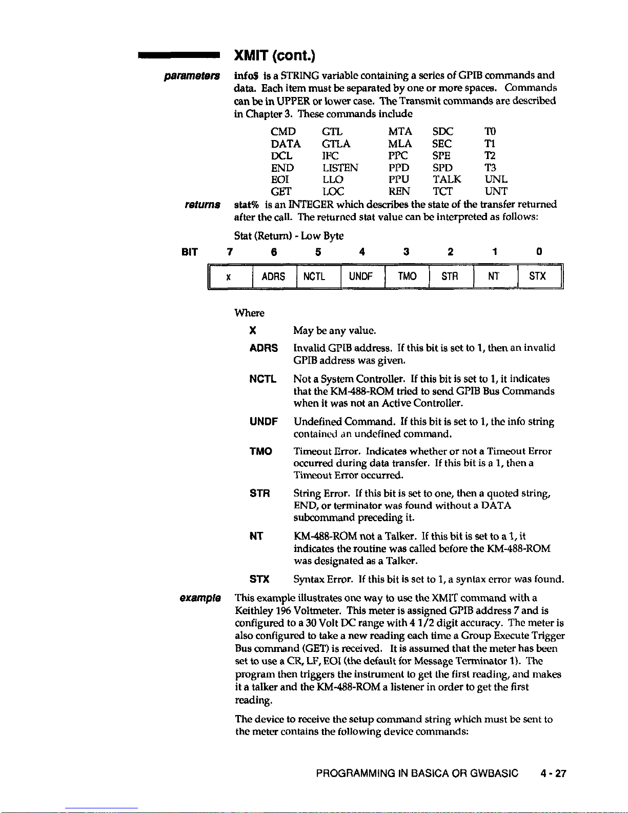
- XMIT (cont.)
psmmeters infa$ is a STRING variable containing a series of GPIB commands and
data. Each item must be separated by one or more spaces.
Commands
can be in UPPER or lower case. The Transmit comman
ds are described
in Chapter 3. These commands include
CMD GTL
MTA SDC M
DATA GTLA MLA
SEC
Tl
DCL
IFC
PIT SPE l-2
END LISTEN
PPD SI’D T3
EOI LLO FPU
TALK UNL
GET LOC
RBN
TCT
UN-r
returns stat% is an INTEGER which describes the state of the transfer returned
after the call. The returned stat value can be interpreted as follows:
Stat (Return) -Low Byte
BIT 7 6 5
4 3 2
1 0
Where
X May be any value.
ADRS
Invalid GPIB address. If this bit is set to 1, then an invalid
GPIB address was given.
NCTL Not a System Controller. If this bit is set to 1, it indicates
that the KM488-ROM tried to send GI’IB Bus Commands
when it was not an Active Controller.
UNDF Undefined Command. If this bit is set to 1, the info string
contained an undefined command.
TM0
Timeout Error. Indicates whether or not a Timeout Error
occurred during data transfer. If this bit is a 1, then a
Timeout Error occurred.
STR String Error. If this bit is set to one, then a quoted string,
END, or terminator was found without a DATA
subcommand preceding it.
NT KM-H&ROM not a Talker. If this bit is set to a 1, it
indicates the routine was called before the KM-488-ROM
was designated as a Talker.
SIX Syntax Error. If this bit is set to 1, a syntax error was found.
example This example illustrates one way to use the XMIT command with a
Keithley 1% Voltmeter. This meter is assigned GPIB address 7 and is
configured to a 30 Volt DC range with 4 l/2 digit accuracy. The meter is
also configured to take a new reading each time a Group Execute Trigger
Bus command (GET) is received. It is assumed that the meter has been
set to use a CR, LF, EOI (the default for Message Terminator I). The
program then triggers the instrument to get the first reading, and makes
it a talker and the KM&Xl-ROM a listener in order to get the first
reading.
The device to receive the setup comman d string which must be sent to
the meter contains the following device commands:
PROGRAMMING IN BASICA OR GWBASIC 4 - 27
Page 68

XMIT (cont.)
Ixl
Select DC Volts mode
R3
Select 30 Volt range
Sl
Select 4 l/2 digit accuracy
T3
Take one reading when GET received
X Execute the prior commands within the string
The device to receive the setup command string must also be
programmed to assert the GPIB REN signal (This allows the meter to
receive GPIB co
mmands.) and to LISTEN (This allows the device to
receive the string.). The programming sequence used consists of the
following:
l
Setting Remote Enable (RBN).
l
Setting all devices to UNTalk and UNListen.
l
Addressing the 196 to LISTEN.
l
Addressing the KM488-ROM to talk (My Talk Address).
l
Sending the Device-Dependent Commands as a string of DATA.
l
Sending the appropriate message terminator characters after the data.
l
Issuing the Group Execute Trigger bus command.
n
Unaddressing all devices.
l
Addressing the meter to TALK and the KM488-ROM to LISTEN (My
Listen Address) in preparation for receiving the latest reading.
- XMITA
pt~rpo~e Transmits data from an array.
offset 200
usage . .
xx XMITA = 200
xx ma*% =
xxOf#% =
xx DIM
INFO% (n%)
XI aount% - z*n%
x1( term% =
xx &at% = 0
xx OfS% = VARpTR(infO%(O))
xx GAIL XMITA(~sg%,of~%,oount%,tsnn%,stat%)
. . .
alternate usage
CALL TARRAY(~og%,of~%,aount%,tsna%, hat%)
4.20 KM-4t38-ROM USER GUIDE
Page 69

- XMITA (cont.)
parameters seg% is an INTEGER representing the segment portion of the memory
address of the data. seg% is set to -1 to the BASICA data segment.
ofs% is an INTEGER representing the offset portion of the memory
address of the data. This is usually obtained using the VARM’R
function. The VARFTR function must be called immediately prior to the
XMITA function call and all variables used within the program must be
declared prior to the VARPTR function. The reason for this is that
BASICA can dynamically allocated storage space and if variables are
declared after the VARPTR call, there is a good possibility that the array
will be relocated and the data will be placed into the wrong location.
count% is an INTEGER containing thhe number of data bytes to be
transmitted. To send more than 32767 bytes, refer to Programming Note
4 in the beginning of this section.
term% is an INTEGER which selects the terminator to be used. This
byte is of the following format:
Term (Input Parameter) -Low Byte
BIT 7
6
5 4 3 2 1 0
STRM
TRMl
TRMO
X X
1 x 1: x
EOI
Where
X This bit may be any value.
STRM Send Message Terminators. If this bit is set to 1, then the
message terminator(s) will bc sent at the end of the
transmission. Otherwise, they will not.
TRMI-0 Terminator Select. These two bits select the Output
Message Terminator to be used to signal the end of a
transmission. Available terminator selections are
TRMl TRMO TERMINATOR # DEFAULT
0 0 0 LF EOI
0 1 1 CR LF Ii01
1
0
2
CR EOI
1 1
3
LF CR Ii01
These terminators can be redefined by running the CONFIG
program as described in Chapter 2.
EOI Asserts EOI. If this bit is set to 1, then EOI will be asserted
when the last byte is sent. Otherwise, EOI will not be
asserted.
returns stat% is an INTEGER describing the state of the transfer returned after
the call. The stat value is interpreted as follows:
Stat (Return) -Low Byte
BIT 7
6 5
4
3
2
1 0
0
0 0 0 TM0 1 0 1’ NT 1 0
PROGRAMMING IN BASlCA OR GWBASIC 4 - 29
Page 70
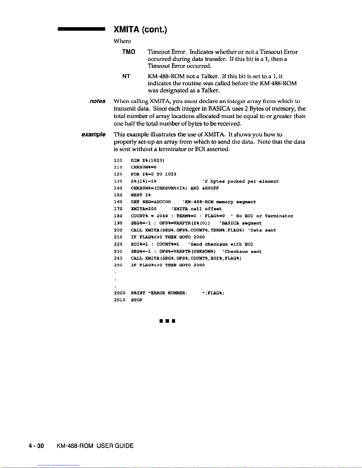
- XMITA (cont.)
Where
TM0
Timeout Error. Indicates whether or not a Timeout Error
occurred during data transfer. If this bit is a 1, then a
Timeout Error occurred.
NT
KM488-ROM not a Talker. If this bit is set to a 1, it
indicates the routine was called before the KM488-ROM
was designated as a Talker.
notes When calling XMITA, you must declare an integer array from which to
transmit data. Since each integer in BASICA uses 2 Bytes of memory, the
total number of array locations allocated must be equal to or greater than
one half the total number of bytes to be received.
exmp/e This example illustrates the use of XMITA. It shows you how to
properly set-up an array from which to send the data. Note that the data
is sent without a terminator or EOI asserted.
4-30
KM-4WROM USER GUIDE
Page 71

Chapter 5
PROGRAMMING IN QUICKBASIC
While Chapter 3 gives a brief overview of the routines available for programming the KM488-ROM, this chapter gives instructions for calling the routines from QuickBASIC. The
routines appear in alphabetical order and include a sample program for each.
5.1 GENERAL
Supported Versions
The Environment
QuickBASIC 4.0 and higher
Before you begin to develop programs in QuickBASIC, several
files must be present in your working directory. Copy the
following files from the KM-488-ROM disks to your working
directory:
QUICKBASIC 4.0 QUICKBASIC 7.O(QBX)
\QB\KM488QB.B1
‘QBKM488QB.BI
KjBKh4488QB4.QLB
/QB\KM488QB7.QLB
KjBKM488QB4.LIB
‘QBKM488QB7.LIB
File Header
Be sure to include the following line within your program:
‘$INCLUDE: ‘km488qb’
Including of this file allows QuickBASIC to check that the correct
number and type of parameters are specified for each routine
called.
Once your QuickBASIC application program has been written,
you will compile the program. Be sure to include full path
names to the various library files where needed.
From within the QuickBASIC Environment
Be sure that the appropriate .QLB file KM488QB4.QLB or
KhU38QB7.QLB) is located where QuickBASIC can find it.
Then, invoke QuickBASIC by typing
FOR QUICKBASIC 4.0
FOR QUICKBASIC 7.O(QBX)
qb /Lkm48llqb4 yourprog
qb /um488qb7 yourprog
where yourprog is the name of your program.
PROGRAMMING IN QuickSASlC 5 - 1
Page 72

Software
To create a Standalone Program
This process compiles the QuickBASIC source code and linka it
to the QuickBASIC and KM-488ROM library files. This process
is slightly different depending on the version of QuickBASIC
used. (See your manual for specifics.) The following example
shows you how to link the files in Version 4.0:
link yo”zprog,, ,baom45tkm4eeqb4;
where
yourprog is the name of your program.
bcom4.5 is the QuickBASIC Runtime library name.
km488qb4 is the linkable BASIC library file.
The KM-488~ROM firmware contains a number of configuration
parameters that govern the default settings of the input and
output message terminator settings, message timeout periods,
and I/O port addresses. The default terminators are shown in
the following table. If these default values are unsatisfactory,
they may be changed by calling either the INTBRM or
OUTTERM routine.
The default DMA and I/O Timeouts are 10 seconds. These
defaults may be altered by calling the DMATIMEOUT or
IOTIMEOUT routine.
Default Temlnator Settlngs
TERM #
OUTPUT TERMINATOR INPUT TERMINATOR
0
LF EOI
LF
1
CRLFEOI
CR
2
CR EOI
, (comma)
3
LFCREOI : (semi-colon)
Programming Notes
1. Any parameters which appear as variables may also be
passed as constants.
2. Parameters which are also used to retorn values must be
declared as variables.
3. Integer variable names end with a percent sign and integer
constants do not contain a decimal point.
4. All integers are treated by the KM-488-ROM routines as
unsigned values (0 to 65535). However, QuickBASIC treats them
as signed magnitudes (-32768 to +32767). When you need to
express a value which is greater than or equal to 32768, you will
need to express it in one of two ways:
l
Convert it to a hexadecimal value. Be sure to prefix these
values with &H when equating them to a variable name. Legal
hexadecimal values range from 0 to &HFFFF and can be used to
represent values from 0 to 65535.
l
Use unsigned values from 0 to 32767 as is, but for values of
32768 to 65535 subtract 65536.
5. Do not name any of your variables with the same name as
those assigned to the KM488-ROM routines.
5-2 KM-488~ROM USER GUIDE
Page 73

5.2 DESCRIPTION FORMAT FOR ROUTINES
The format for each descriptions is as follows:
Pwtwse
usage
alternate usage
parameters
returns
notes
example
5.3 ROUTINES
purpose
usage
alternate usage
parameters
returns
example
. . . a brief description of the routine.
See Chapter 3 for more detailed
descriptions.
. . . gives an example of usage for each routine and assumes the input
parameters are passed in as variables. These parameters can also be
passed in directly. See the General Programming Notes for more
information.
. . . lists alternate usage for the routine, if any.
Unless otherwise noted, the
alternate usage performs exactly the same function as the usage.
. . . describes each of the input parameters.
. . . describes any values returned by the routine.
. . . lists any special programming considerations.
. . . gives a programming example using the routine.
DMATIMEOUT
Sets the maximum length of time for a DMA transfer to complete before
a timeout error is reported. (See RCVA and XMITA routine
descriptions.)
CArtL DMATIMEOOT (time%,
CALL SETTIMEOUTkhne%)
NOTE: The alternate usage sets both the DMA and I/O Timeouts to the
specified value.
time%
is an INTEGER which represents the timeout period to elapse
during a DMA transfer. A DMA Timeout Error will be generated when
the time to transfer (via DMA) an entire message exceeds the set DMA
timeout value (time). time% can range from 0 to 65535 milliseconds and
is internally rounded to the closest integer multiple of 55 milliseconds.
For values greater than or equal to 32768, time must be represented
differently. See Programming Note 4 at the begining of this section.
This example sets the DMA Timeout period to 5 seconds.
DMA
TIMEOUT (5000)
PROGRAMMING IN QuickBASIC
5-3
Page 74
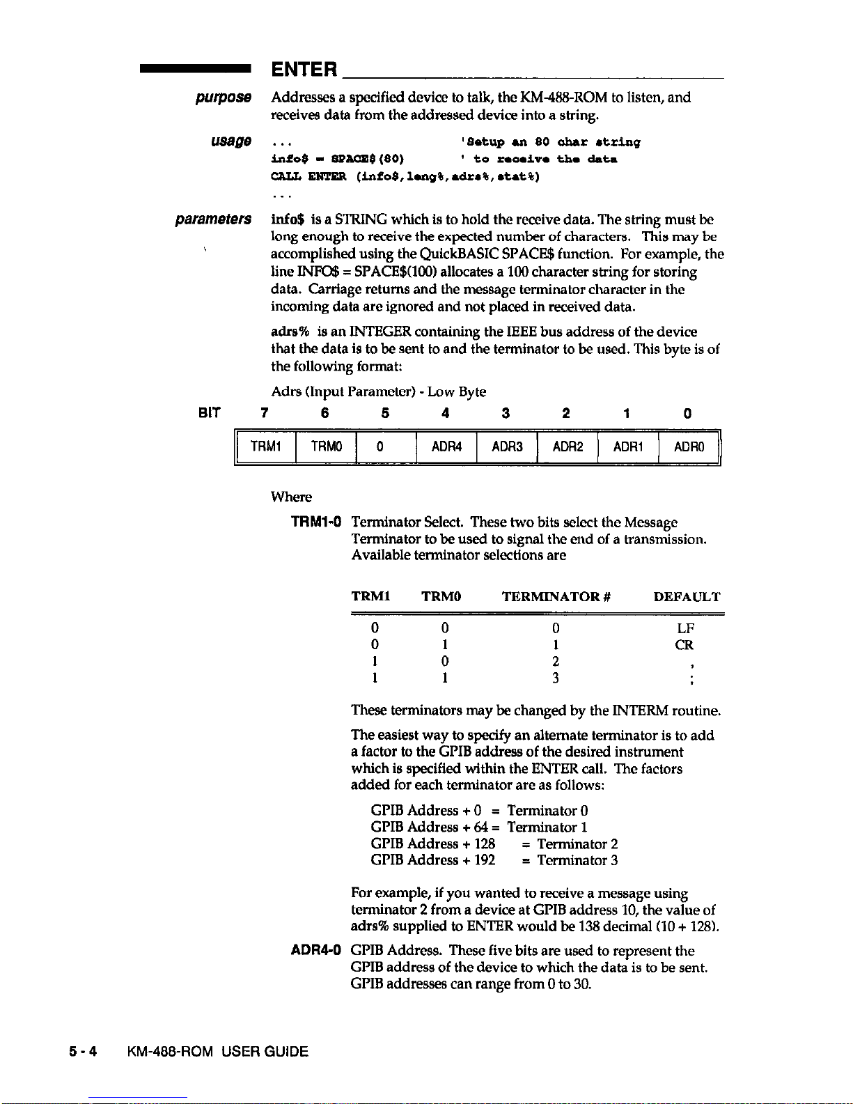
- ENTER
purpose Addresses a specified device to talk, the KM4!8-ROM to listen, and
receives data from the addressed device into a string.
usage . . .
'8etup an 80 ahar l tring
i&0$ - sPAcs$(50)
1 to rsooivs tho data
caIJ4 EUTER (info$,lmlg%,a&a%, *tat%)
parameters lnfo$ is a STRING which is to hold the receive data. The string must be
long
enough
to receive the expected number of characters.
This may be
accomplished using the QuickBASIC SPACB$ function. For example, the
line INFo$ = SPACE$(lOO) allocates a 100 character string for storing
data. Carriage returns and the message terminator character in the
incoming data are ignored and not placed in received data.
a&% is an INTEGER containing the IEEE bus address of the device
that the data is to be sent to and the terminator to be used. This byte is of
the following format:
Adrs (Input Parameter) - Low Byte
BIT 7
6
5 4
3
2
1
0
TRMl
TRMO 0
ADR4 ADR3 ADR2
ADRI ADRO
Where
TRMl-0
ADR4-0
Terminator Select. These two bits select the Message
Terminator to be used to signal the end of a transmission.
Available terminator selections are
TRMl TRMO
TERMINATOR #
DEFAULT
0 0
0
LF
0 1
1 CR
1
0
2
1 1
3
These terminators may be changed by the INTERM routine.
The easiest way to specify an alternate terminator is to add
a factor to the GPIB address of the desired instrument
which is specified within the ENTER call. The factors
added for each terminator are as follows:
GPIB Address + 0 = Terminator 0
GPIB Address + 64 = Terminator 1
GPIB Address + 128 = Terminator 2
GPIB Address + 192 = Terminator 3
For example, if you wanted to receive a message using
terminator 2 from a device at GPIB address 10, the value of
adrs% supplied to ENTER would be 138 decimal (10 + 128).
GPIB Address. These five bits are used to represent the
GPIB address of the device to which the data is to be sent.
GPIB addresses can range from 0 to 30.
5-4 KM-468~ROM USER GUIDE
Page 75
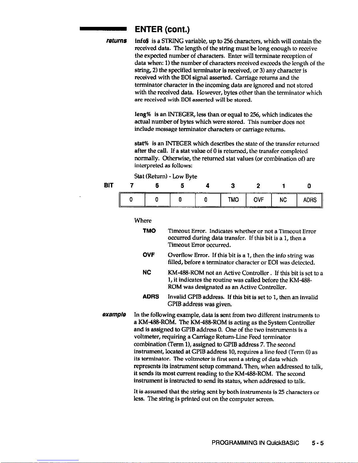
- ENTER (cont.)
returns Info8 is a STRING variable, up to 256 characters, which will contain the
received data. The length of the string must be long enough to receive
the expected number of characters. Enter will terminate reception of
data when: 1) the number of characters received exceeds the length of the
string, 21 the specified terminator is received, or 31 any character is
received with the EOI signal asserted. Carriage returns and the
terminator character in the incoming data are ignored and not stored
with the received data.
However, bytes other than the terminator which
are received with EOI asserted will be stored.
leng%
is an INTEGER, less than or equal to 256, which indicates the
actual number of bytes which were stored. This number does not
include message termmator characters or carriage returns.
stat%
is an INTEGER which describes the state of the transfer returned
after the call. If a stat value of 0 is returned, the transfer completed
normally. Otherwise, the returned stat values for combination of) are
interpreted as follows:
Stat (Return) -Low Byte
BIT 7
6 5
4
3
2
1 0
0
0 0 0
TM0 OVF NC ADRS
Where
TM0
Timeout Error. Indicates whether or not a Timeout Error
occurred during data transfer. If this bit is a 1, then a
Timeout Error occurred.
OVF
Overflow Error. If this bit is a 1, then the info string was
filled, before a terminator character or EOI was detected.
NC KM-488ROM not an Active Controller. If this bit is set to a
1, it indicates the routine was called before the KM-488-
ROM was designated as an Active Controller.
ADRS
Invalid GPIB address. If this bit is set to 1, then an invalid
GPIB address was given.
example In the following example, data is sent from two different instruments to
a KM-488-ROM. The KM-488ROM is acting as the System Controller
and is assigned to GPIB address 0. One of the two instruments is a
voltmeter, requiring a Carriage Return-Line Feed terminator
combination (Term 11, assigned to GPIB address 7. The second
instrument, located at GPIB address 10, requires a line feed (Term 01 as
its terminator. The voltmeter is first sent a string of data which
represents its instrument setup command. Then, when addressed to talk,
it sends its most current reading to the KM-I88-ROM. The second
instrument is instructed to send its status, when addressed to talk.
It is assumed that the string sent by both instruments is 25 characters or
less. The string is printed out on the computer screen.
PROGRAMMING IN QuickBASiC
5 - 5
Page 76

ENTER (cont.)
purpose
usage
alternate usage
parameters
INIT
Initializes the KM-488-ROM by assigning its GLIB address and
establishing it as a System Controller or Device.
CALL
INIT
(a&#%,m&%)
CALL INITIALINE (dr~%,m~&%)
adrs% is an INTEGER representing the IEEE bus address of the KM-488-
ROM. This is an integer from 0 to 30.
mode% is an INTEGER representing the operating mode of the KM-488ROM. These can be any of the following values:
Mode - Low Byte
BIT 7
6
5 4 3 2 1 0
X X
X
X
X
FAST
DEV X
Where
X
May be any value.
FAST
Handshake Speed. If this bit is set to 1, High Speed GPIB
bus handshaking will be used(5OOns.). If it is set to 0, Low
Speed GI’IB bus handshaking (2 s.) will be used. See
Chapter 3 for more information regarding the handshake
Speed.
5-6
KM-466~ROM USER GUIDE
Page 77
- INIT (cont.)
DEV
Device. If this bit is set to 1, then the KM488-ROM is acting
as a Device. Otherwise, when this bit is set to 0, the KM48EROM is acting as a System Controller. When System
Controller is selected, the GPIB IFC line is momentarily
asserted.
returns None.
exampte This example initializes the KM-488-ROM as a System Controller with a
IEEE address of 0 with a High Speed Handshake.
CALL
IPIT (0.4)
- INTERM
purpose Changes the input message terminator settings.
usage
CALL ImmN(num%.tsrm%)
alternate usage
CALL sETTkmJTEos
(term%)
NOTE: The Alternate Syntax will only change the value of Input
Message Terminator 0.
parameters num% is an integer which selects the number of the receive message
terminator to be changed. This ranges from 0 to 3, where
IlUlN%
TERMINATOR #
DEFAULT
0 0
1 1
2 2
3 3
term%
is an integer representing the terminator byte to be programmed.
This integer is the decimal or hex equivalent of the terminator’s ASCII
representation. Hex equivalents must be preceded by &H. See Appendix
A for ASCII Equivalents.
returns None.
eXamp/e
This example sets Input Terminator 3 to Line Feed (Hex A).
cJlLL
INTam4(3,CNA)
- IOTIMEOUT
purpose Changes the length of time to elapse before an I/O Timeout occurs.
usage . . .
GAIL
1oT1mE0uT
(tAIm%)
PROGRAMMING IN QuickBASIC
5 - 7
Page 78
- IOTIMEOUT (cont.)
parameters time% is the time elapsed before a timeout error is reported. This
occurs if the time elapsed between the transfer of individual bytes
exceeds the specified I/O Timeout period.
time% is between 045535 ms,
internally rounded to the closest multiple of 55 ms. ‘Ike default is 10
seconds.
returns None.
eXampte This sets the I/O timeout to 1 second.
CALL IOTI~O'JT(1000)
- OUTTERM
purpose Changes the output message terminator sequences.
usage CALL
OuTTERU(n~%,~r*%,~i%,tnnl%,trm2%)
alternate usage
CAwl SSTOUTPUTSOS(tnnl%,tm2%)
NOTE: The Alternate Syntax will only change the value of Terminator 0,
and will always assert EOI
upon
the transmission of the last character.
In addition, a single character terminator is programmed by setting
bTnz% to 0.
parameters num% is an INTEGER which selects the number of the transmit
message terminator to be changed. This ranges from 0 to 3, where:
num%
TERMINATOR #
DEFAULT
0 0
LF EOI
1
1
CRLFEOI
2
2
CREOI
3
3
LFCREOI
chars% is an INTEGER that selects the length of the transmit terminator.
This is 0 if a l-character terminator is required or 1 for a 2-character
terminator.
eoi% is an INTEGER that determines whether EOI is asserted when the
last terminator byte is sent. If this bit is 1, EOI will be sent. If this bit is 0,
EOI will not be sent.
&ml% is an INTEGER representing the first terminator byte to be sent;
it is the decimal or hex equivalent of the terminator’s ASCII
representation. Be sure to precede all hex values with &H. See Appendix
A for ASCII Equivalents.
4~~2% is an INTEGER representing the second terminator byte ( in a 2.
byte terminator); it is the decimal or hex equivalent of the terminator’s
ASCII representation. Be sure to precede all hex values with &H. If a l-
byte terminator is programmed, trm2% may be any value.
returns None.
example This example sets Output Terminator 1 to Carriage Return, Line Feed,
EOI.
CALL 0UTTERM(1,1,1,CED,CHI)
5-8
KM-488-ROM
USER GUIDE
Page 79
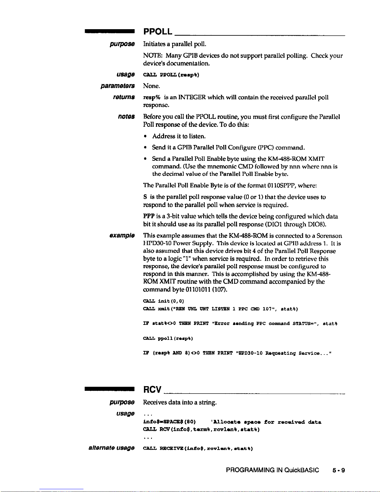
usage
parameters
returns
notes
Purpose
usage
alternate usage
PPOLL
Initiates a parallel poll.
NOTE: Many GPIB devices do not support parallel polling. Check your
device’s documentation.
CALL PRCLL
(ramp%)
None.
reap%
is an INTEGER which will contain the received parallel poll
response.
Before you call the PI’OLL routine, you must first configure the Parallel
Poll response of the device. To do this:
l
Address it to listen.
l
Send it a GI’IB Parallel Poll Configure (WC) command.
l
Send a Parallel Poll Enable byte using the KM-488-ROM XMIT
command. (Use the mnemonic CMD followed by
nnn where mm
is
the decimal value of the Parallel Poll Enable byte.
The Parallel Poll Enable Byte is of the format OllOSPPP, where:
S is the parallel poll response value (0 or 1) that the device uses to
respond to the parallel poll when service is required.
PPP is a 3-bit value which tells the device being configured which data
bit it should use as its parallel poll response (DIOI through DIOS).
This example assumes that the KM488-ROM is connected to a Sorenson
HPD30-10 Power Supply. This device is located at GPIB address 1. It is
also assumed that this device drives bit 4 of the Parallel Poll Response
byte to a logic “1” when service is required. In order to retrieve this
response, the device’s parallel poll response must be configured to
respond in this manner. This is accomplished by using the KM-488ROM XMIT routine with the CMD command accompanied by the
command byte 01101011(107).
cau hlit.(O,O)
RCV
Receives data into a string.
. . .
i&0$-SPACE8 (80)
'AlloLTatm l paaa ior roooivo* d&r
GAIL RCV(info$,tsrm%,r~lsn%,*t~t%)
1..
CALL ~~~(info$,rc"lur%,‘t.t$)
PROGRAMMING IN QuickBASIC
5 - 9
Page 80

- RCV (cont.)
NOTE: The Alternate Syntax assumes the use of Input Message
Terminator 0.
parameters
info$ is a STRING which will hold the received data. Prior to calling
RCV, you must initialize a string which is long enough to receive the
expected number of characters. This may be accomplished using the
QuickBASIC SPACE$ function. For example, the line INFO8 =
Sl’ACE$WC0 allocates a 100 character string for storing data. Carriage
returns and the message terminator character in the incoming data are
ignored and are not stored with the received data.
term% is an INTEGER containing the number of the IEEE bus
terminator to be used, where:
term%
TERMINATOR # DEFAULT
0
0
LF
1
1 CR
2
2
3
3
These terminators can be changed by calling the INTERM routine.
returns Mo$ is a STRING variable (up to 64 KBytesI which will contain the
received data. The length of the string must be long enough to receive
the expected number of characters. RCV will terminate reception of data
when: 1) the number of characters received exceeds the length of the
string, 21 a terminator is received, or 3) any character is received with the
EOI signal asserted. Carriage returns and the message terminator
character in the incoming data are ignored and not stored with the
received data.
rcvlen% is an INTEGER which indicates the actual number of bytes
which were received and stored.
stat% is an INTEGER which describes the state of the transfer returned
after the call. The returned stat values are interpreted as follows:
Stat (Return) - Low Byte
BIT 7
6
5 4 3
2 1 0
0 0
0
0 TM0
OVF NL 0
TM0
Ttmeout Error. Indicates whether or not a Timeout Error
occurred during data transfer. If this bit is a 1, then a
Timeout Error occurred.
OVF
Overflow Error. If this bit is a 1, then the info string was
filled, before a terminator character or EOI was detected.
NL KM-488-ROM not a Listener. If this bit is set to a 1, it
indicates the RCV was called before the KM488-ROM was
designated as a Listener.
notes The KM4WROM must be addressed to listen and another device
addressed to talk before calling RCV.
J-10
KM-W&ROM USER GUIDE
Page 81
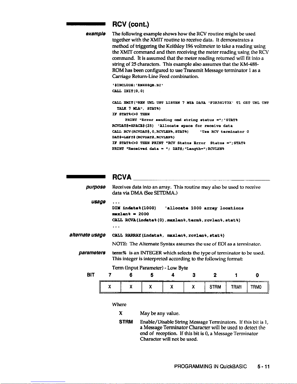
- RCV (cont.)
example The following example shows how the RCV routine might be used
together with the XMIT routine to receive data. It demonstrates a
method of triggering the KeithIey 196 voltmeter to take a reading using
the XMIT command and then receiving the meter reading using the RCV
command. It is assumed that the meter reading returned will fit into a
string of 25 characters. This example also assumes that the KM-488ROM has been configured to use Transmit Message terminator 1 as a
Carriage Return-Line Feed combination.
Purpose
usage
RCVA
Receives data into an array. This routine may also be used to receive
data via DMA (See SETDMA.)
. . .
DIM in&t*% (1000)
'allooats 1000 .rray looations
maxlen% - 2000
Cw
W”A(in&t&(O)
,mulsn%,tsrm%,r~vlon$,.t~t%)
. . .
alternate usage
paremeters
CALL stAmAY(in&ta%, msrlsn%,ravlm%,*tat%)
NOTE: The Alternate Syntax assumes the use of EOI as a terminator.
term%
is an INTEGER which selects the type of terminator to be used.
This integer is interpreted according to the following format:
Term (Input Parameter) -Low Byte
BIT 7
6 5
4
3
2 1
0
X
X
X X X
STRM
TFiMl TRMO
Where
X May be any value.
STRM
Enable/Disable String Message Terminators. If this bit is 1,
a
Message Terminator Character will be used to detect the
end of reception. If this bit is 0, a Message Terminator
Character will not be used.
PROGRAMMING IN QuickBASIC 5-11
Page 82

RCVA (cont.)
TRMl-0
Terminator Select. These two bits select the Input Message
Terminator to be used to signal the end of a transmission.
(The STRM bit must be set to 1.) Available terminator
selections are
TRMl TRMO
TERMINATOR #
DEFAULT
0 0
0
LF
0
1 1 CR
1 0
2
1
1
3
The values for these terminators can be changed by calling
the INTERM routine.
maxlen% is an integer which specifies the maximum number of data
bytes which can be received. When you want to receive more than 32767
bytes, use the technique outlined in Programming Note 4 presented at
the beginning of this section. maxlen% must be less than or equal to
twice the total number of bytes allocated in the indata% array or a
program crash may occur.
refurfls
indata% is an array which will contain the received data. All characters
received are stored.
rcvlen% is an integer which will contain the actual number of data bytes
which were received. Note that half this many array locations will
contain data. To specify more than 32767 bytes, use the technique
outlined in Programming Note 4 presented at the beginning of this
section.
stat% is an integer describing the state of the transfer returned after the
call. The RCVA routine returns three status bits within the stat%
variable. The TM0 bit is used to signal a timeout error. The REOI bit
signals that the routine returned because the terminator was detected (if
enabled), or EOI was received. The NL bit is set if the RCVA routine was
called and the card was not addressed to listen. Unlike other KM-488ROM routines, it is possible to return a non-zero status when the call was
completed successfully.
Stat (Return) - Low Byte
BIT 7
6 5
4
3 2
1
0
0
0
REOI 0
TM0 0
NL 0
Where
REOI Reason for RCVA Termination. If this bit is a 1, then RCVA
routine ceased because an EOI or terminator character was
received. If this bit is a 0, then the RCVA was terminated
because an error occurred or the maximum byte count was
reached.
TM0
Timeout Error. Indicates whether or not a Timeout Error
occurred during data transfer. If this bit is a 1, then a
Timeout Error occurred.
5.12 KM-488~ROM USER GUIDE
Page 83

- RCVA (cont.)
NL KM488-ROM not a Listener. If this bit is set to a 1, it
indicates the RCVA was called before the Kh4488-ROM
was designated as a Listener.
/10fe8
The KM488-ROM must be addressed to listen before calling this routine.
example Refer to the XMITA example.
- SEND
purpose Addresses a specified device to listen, the KM488-ROM to talk, and
sends data from a string.
usage
info$
- “d&a to be trmmdttd”
CAT& sm (a&*%,info$,*t~tu~%)
parameters adrs% is an INTEGER containing the IEEE bus address of the device
that the data is to be sent to and the terminator to be used. This byte is of
the following format:
Adrs (Input Parameter) -Low Byte
BIT 7
6 5
4 3 2
1
0
TRMI TRMO 0 ADR4 ADR3 ADR2
ADRl ADRO
Where
TRMl-0 Terminator Select. These two bits select the Input Message
Terminator to be used to signal the end of a transmission.
Available terminator s&ctions are
TRMl TRMO
TERMINATOR # DEFAULT
0 0 0
LF
0 1 1 CR
1
0 2
1 1
3
The values for these terminators can be changed by running
the CONFIG program as described in Chapter 2.
The easiest way to specify an alternate terminator is to add
a factor to the GPIB address of the desired instrument
which is specified within the SEND call. The factors added
for each terminator are as follows:
GPIB Address + 0 = Terminator 0
GPIB Address + 64 = Terminator 1
GPIB Address + 128 = Terminator 2
GPIB Address + 192 = Terminator 3
For example, if you wanted to send a message using
message terminator 2 to a device at GPIB address 10, the
value of adrs% supplied to SEND would be 138 decimal (10
+ 128).
PROGRAMMING IN QuickBASIC
5-13
Page 84

- SEND (cont.)
AOFM-0
GPIB Address. These five bits are used to represent the
GPIB address of the device to which the data is to be sent.
GPIB addresses can range from 0 to 30.
ix&$ is a STRING (256 chars max.) containing the data to be sent.
returns stat% is an INTEGER describing the state of the transfer returned after
the call. The returned stat values (or combination of) are interpreted as
follows:
Stat (Return) -Low Byte
BIT 7 6
5 4 3 2
1 0
Where
TM0
Timeout Error. Indicates whether or not a Timeout Error
occurred during data transfer. If this bit is a 1,
then a
Timeout Error occurred.
NC
Not Active Controller. If this bit is a 1, then the SEND
routine was called when the KM488-ROM was not an
Active Controller.
ADRS Invalid Address. If this bit is set to a 1, an invalid IEEE488
device address was given.
examp/e This example shows how to send data from a KM488-ROM to a device.
The KM488-ROM is initialized as a System Controller located at GPIB
address 10. The KM488-ROM uses high-speed handshaking. The data
(a device setup string) is sent to a device located at GPIB address 12.
‘~I”cLuDs:‘sn1*8QB’
CALL INTT,lll,1,
As
an alternative, the following sequence can be used:
- SETBOARD
purpose In a multiple board system, identifies the KM488-ROM to be
programmed.
usage cam kmmmto
(board%)
alternate usage
CALL BOARDSELECT (board%)
5-14
KM-488-ROM USER GUIDE
Page 85

parameters
returns
notes
example
wwse
usage
alternate usage
parameters
returns
notes
SETBOARD (cont.)
board% is an INTEGER between 0 and 3 which represents the board to
be programmed. Note that up to four boards can be installed in any one
system. The board% “number” is associated with the base address of its
I/O port.
None.
You must assign a board “number” for every KM438-ROM in the system
before calling the SETBOARD routine. Board numbers are assigned
using the SETPORT routine.
Each board must be must be initialized independently by calling the
lNIT routine. You must do this the first time a given board is selected,
before any other operations are conducted on that board.
Once a board has been selected using SETBOARD, all further I/O
operations will be performed on that board until the
next
SETBOARD is
executed.
This example line selects board “2” for communication.
SETBOXD(2)
SETDMA
NOTE: DMA allows maximum data transfer rates
in excess of
100
kilobytes per second. However, the actual data rates are limited by the
rates at which other devices connected to the bus can send or receive
data. These rates are governed automatically by the GPIB handshaking
signals.
Allows the use of DMA in conjunction with the XMITA and RCVA
routines.
CALL 8ETDI(R(ohuursl%)
CAL& Eamcamm(ahMnSl%)
channel% is an INTEGER which specifies the DMA channel to be used
for the data transfer. channel% can be from 1 to 3, where:
1 = Use DMA channel 1.
2 = Use DMA channel 2.
3 = Use DMA channel 3.
To disable DMA. set channel% to a value other than 1,2 or 3.
None.
The DMA hardware jumpers must be properly set for the DMA channel
selected by SETDMA. Note that the default setting for the jumpers is
DMA DISABLED. The jumpers are further described in Chapter 2.
When SETDMA is called to enable the use of DMA, each call to the
XMlTA and RCVA routines that follows will use DMA to accomplish the
transfer until SETDMA is called with a parameter outside the range of l-
3.
PROGRAMMING IN QuickBASIC
5-15
Page 86
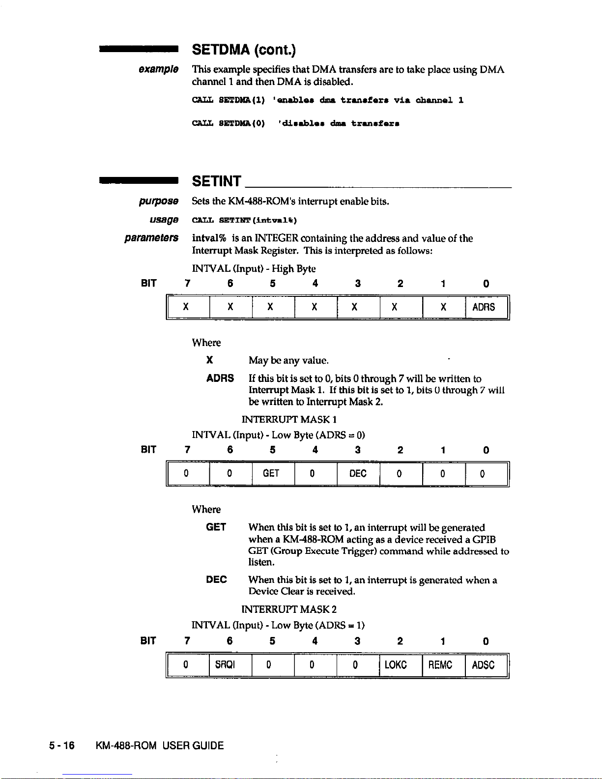
- SETDMA (cont.)
example This example specifies that DMA transfers are to take place using DMA
channel 1 and then DMA is disabled.
CALL SETDIdA(1) 'enabloa dnu trurafsra via ahannol 1
-
SETINT
purpose Sets the KM-488-ROM’s interrupt enable bits.
usage CALL
SETIm
(intval%)
parameters
intval% is an INTEGER containing the address and value of the
Interrupt Mask Register. This is interpreted as follows:
INTVAL (Input) - High Byte
BIT 7 6 5 4
3
2 1
0
X X
X
X X
X X ADRS
Where
X May be any value.
ADRS
If thls bit is set to 0, bits 0 through 7 will be written to
Interrupt Mask 1. If this bit
is set to 1, bits 0 through 7 will
be written to Interrupt Mask 2.
INTBRRUI’T MASK 1
INTVAL (Input) -Low Byte (ADRS = 01
BIT 7 6 5 4
3
2 1
0
0 0 GET 0
DEC
0 0 0
Where
GET
DEC
When thls bit is set to 1, an interrupt will be generated
when a KM438-ROM acting as a device received a GPIB
GET (Group Execute Trlgge;) command while addressed to
listen.
When this bit is set to 1, an interrupt is generated when a
Device Clear is received.
INTBRRUIT
MASK 2
INTVAL (Input) -Low Byte (ADRS = 1)
BIT 7 6
5 4 3
2 1
0
0
Stml
0 0 0
LOKC REMC ADSC
5-16 KM-488~ROM USER GUIDE
Page 87

- SETINT (cont.)
Where
SRQI
When thls bit is set to 1, an interrupt is generated when
SRQ is received.
LOKC
When this bit is set to 1, an interrupt is generated when the
state of the Local Lockout bit changes.
REMC
When this bit is set to 1, an interrupt is generated when the
state of the Local/Remote bit changes.
ADSC
When this bit is set to 1, an interrupt is generated when the
state of the LA, TA, or CIC bits within the address status
register changes.
returns None.
notes Be certain to assign the KM488-ROM to an interrupt level before using
this routine. Interrupt Levels are assigned by means of a jumper on the
KM-488-ROM board. This
jumper is
described in detail in Chapter 2.
You must set-up an interrupt handling routine within the QuickBASIC
program to deal with the interrupt condition.
example Thls example enables the KM488-ROM to generate an interrupt
when
SRQ is received.
Cw SETINT(&EltO)
- SETPORT
purp088
This routine is used to alter the range of addresses used by the KM-488ROM’s I/O port. In a multiple board environment, it is also used to
associate a given range of I/O addresses with a board number.
usage
CA&L
SETRCRT
(board%, ioport%)
PeJZVrIeterS board% is an INTEGER between 0 and 3 which represents the board to
be programmed. Note that up to four boards can be installed in any one
system. The board% “number” is associated with the base address of its
I/O ports.
ioport%
is an INTEGER representing the I/O Base Address of the KM488-ROM. The default Base Address is 288 Hex. The Base Address
selected must match the one selected by the Base Address Switch on the
KM-488-ROM. (See Chapter 2 for
more
information.)
returns
None.
notes When multiple boards are used, each board must have its own unique
base address. Any Base Address can be assigned to any board number,
provided that none of the base addresses overlap.
example This line assigns Board 0 an I/O Base Address of 300h.
*stpoa
(0, CE300)
PROGRAMMING IN QuickBASIC
5-17
Page 88

- SETSPOLL
piNpOSe
Defines the Serial Poll Response of a KM-N+ROM acting as a device
(non-Controller).
usage
CALL
BETSPOIL
(rasp%)
fXtrar#re(efS
reap% is an INTEGER describing the serial poll response and the state of
the SRQ bit. This byte is of the following format:
Resp% (Input) - Low Byte
BIT 7 6
5 4 3 2
1
0
SPR6 RSV SPR6 SPR5
SPR4
SPR3
SPR2
SPRl
Where
SPRl-6
Bits 1 through 8 of this device’s Serial Poll Response Byte.
Ftsv If this bit is 1, SRQ will be asserted to request servicing.
Otherwise, SRQ will not be asserted.
returns None.
oXample
This example illustrates a common use of SETSPOLL.
req.% = 0
purpo=
usage
parameters
returns
SPOLL
Performs a serial poll of the specified device.
CALL sPOLL(.dr.%,re.p%,.t*+%)
adrs% is an INTEGER containing the IEEE bus address of the device
that is to be serial polled. This can range from 0 to 30.
resp% is an INTEGER containing the serial poll response received. The
definition of this integer varies from device to device; however, Bit 6 is
always used to indicate whether the device is in need of service. Consult
the manufacturer’s operator’s manual for more information.
stat% is an INTEGER describing the state of the transfer returned after
the call. The stat value is interpreted as follows:
Stat (Return) -Low Byte
BIT
7 6
5 4
3 2
1 0
0 0
0 0
TM0 0
NC ADR
6-16
KM-466~ROM USER GUIDE
Page 89

- SPOLL (cont.)
Where
TM0
NC
Indicates whether a Timeout Error occurred during data
transfer. If a 1, then a Timeout Error occurred.
KM4?8-ROM not a Controller. If set to a 1, it indicates the
routine was called before the KM-488-ROM was designated
as an Active Controller.
ADR Invalid GPIB Address. If this bit is set to 1, an invalid GPIB
address was provided.
&%3m~/e This example illustrates a simple serial poll of a device located at GPIB
address 10.
- SRQ
purpose Detects the presence of the GPIB SRQ signal.
usage IP (SRW) TBeU
parameters None.
returns The SRQ function returns a 0 or FALSE when not present, or a 1 or TRUE
when present.
notes The value returned by SRQ is generally used within a conditional branch
in an application program.
Note that after obtaining a TRUE response from SRQ, SRQ response is
reset to FALSE even if the SRQ line is still active. In order to reset the
SRQ response to TRUE, you must serial poll at least one device with a
requesting service. Conducting a serial poll on a device requesting
service resets its SRQ line. Then, if other devices were simultaneously
asserting SRQ, the output of SRQ will be reset to TRUE. Otherwise, SRQ
becomes TRUE on the next SRQ assertion.
examp/e This example assumes that the KM-488-ROM is connected to an
instrument located at GPIB address 1 and capable of requesting service
via SRQ. When SRQ is detected, the SPOLL function is called and the
serial poll response of the device is printed to the computer screen.
‘$IwCLmE:
‘km488qb.k.i
IF moo) THRW
PROGRAMMING IN QuickBASIC 5-19
Page 90
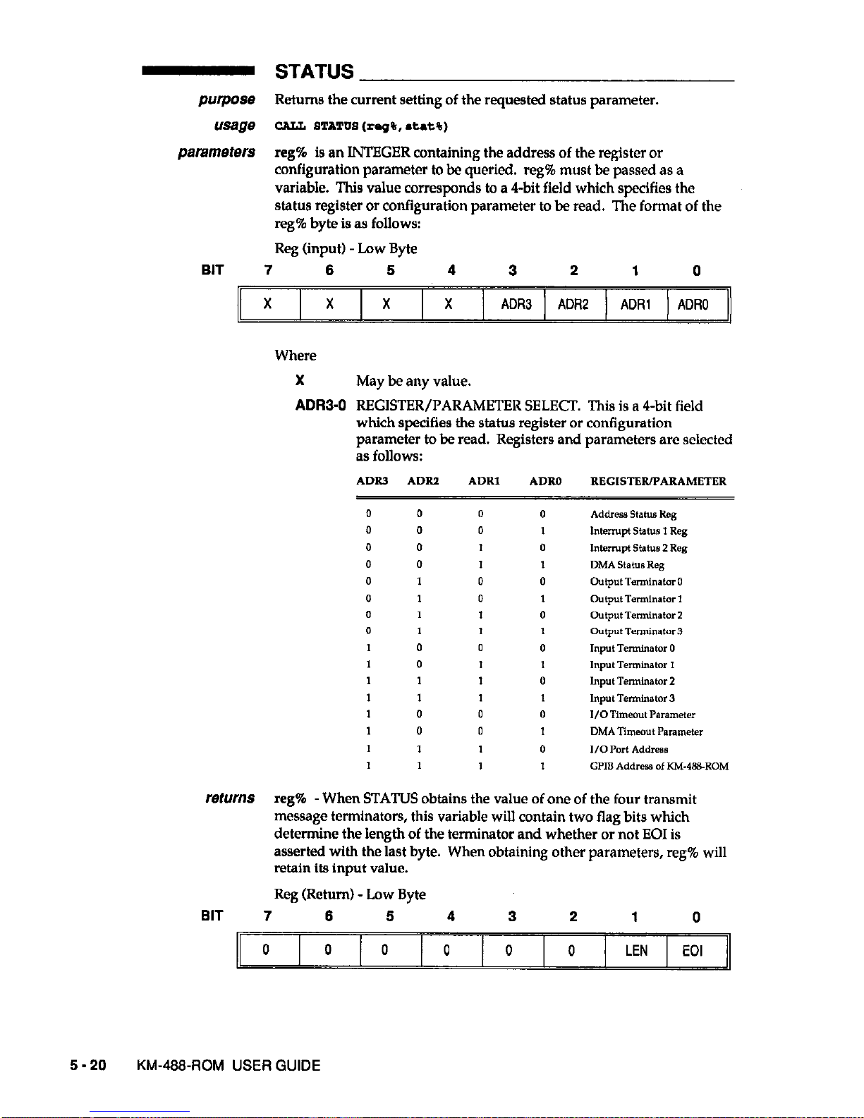
- STATUS
purpose Returns the current setting of the requested status parameter.
usage
CAL&
STATUS
(rep%, .t.t%)
parameters
reg% is an INTEGER containing the address of the register or
configuration parameter to be queried. reg% must be passed as a
variable. This value corresponds to a 4-bit field which specifies the
status register or configuration parameter to be read.
The format of the
reg% byte is as follows:
Reg (input) - Low Byte
BIT 7
6
5 4
3
2
1
0
X
X
X X ADR3 ADR2 ADRl ADRO
Where
X
May be any value.
ADRS0
REGISTER/PARAMETER SELECT. This is a 4-bit field
which specifies the status register or configuration
parameter to be read. Registers and parameters are selected
as follows:
ADRS ADIU ADRI
ADRO REGlS”?RmARAMRTER
returns
reg% -When STATUS obtains the value of one of the four transmit
message terminators, this variable will contain two flag bits which
determine the length of the terminator and whether or not EOI is
asserted with the last byte. When obtaining other parameters, reg% will
retain its input value.
Reg (Return) - Low Byte
BIT 7
6
6 4 3
2
1 0
0 0
0
0 0 0 LEN
EOI
5-20
KM-466-ROM USER GUIDE
Page 91
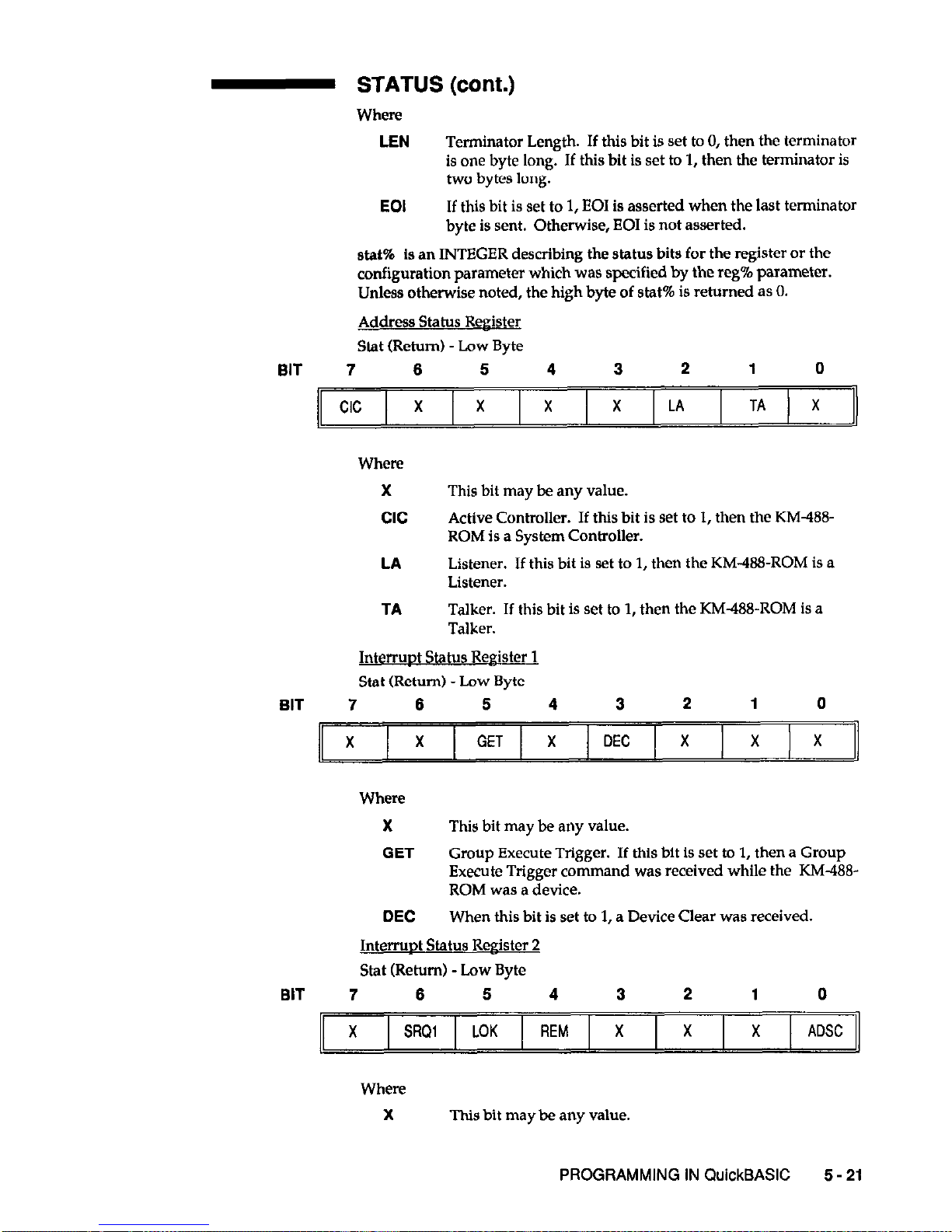
- STATUS (cont.)
Where
LEN
Terminator Length. If this bit is set to 0, then the terminator
is one byte long. If this bit is set to 1, then the terminator is
two bytes long.
EOI
If this bit is set to 1, EOI is asserted when the last terminator
byte is sent. Otherwise, EOI is not asserted.
stat% is an INTEGER describing the status bits for the register or the
configuration parameter which was specified by the reg% parameter.
Unless otherwise noted, the high byte of stat% is returned as 0.
Address Status Register
Stat (Return) -Low Byte
BIT 7 6
6 4 3
2 1 0
Where
X
cc
LA
TA
This bit may be any value.
Active Controller. If this bit is set to 1, then the KM488-
ROM is a System Controller.
Listener. If this bit is set to 1, then the KM-4&3-ROM is a
Listener.
Talker. If this bit is set to 1,
then
the KM-488-ROM is a
Talker.
InterruDt Status Reeister 1
Stat (Return) -Low Byte
BIT 7 6
6 4 3
2 1 0
Where
X This bit may be any value.
GET
Group Execute Trigger. If this bit is set to 1, then a Group
Execute Trigger comman
d was received while the KM-488-
ROM was a device.
DEC
When this bit is set to 1, a Device Clear was received.
Interruot Status Resister 2
Stat (Retorn) - Low Byte
BIT 7 6
6 4
3
2
1 0
X SRQl LOK
REM X
X
X ADSC
Where
X
This bit may be any value.
PROGRAMMING IN QuickBASIC 6-21
Page 92

- STATUS (cont.)
SRQI
When this bit is set to 1, it indicates SRQ was active. (Active
Controller mode only.)
LOK
When this bit is set to 1, the device was set to Local Lockout.
(Device mode only.)
REM
When this bit is set to 1, the device was configured for
remote operation. (Device mode only.)
ADSC
When this bit is set to 1, a change of the address status
occurred (i.e., untalk to talk, device to active controller, etc.).
Transmit and Receive Messave Terminator #l-4. Contains First and Last
bytes of the message terminator. Input Terminators and Single
Character Output Terminators are contained in the Least Significant
Byte. In the case of a two character Output Terminator, the Most
Significant Byte of this parameter is the first character sent.
DMA Timeout and I/O Timeout Parameters. Contains the value of the
desired parameter as an unsigned value in the low and high bytes of
stat%. The timeout value is expressed in milliseconds (065535).
notes The bits contained in the Interrupt Status 1 and 2 registers are extremely
volatile. When you read these registers, any bits which were set are
automatically cleared by the READ operation. This is extremely
important to note when reading Interrupt Status Register 1, as some of
the bits (not shown above) are used by various KM-@&ROM routines.
It may be possible to cause various KM-488-ROM routines to report a
timeout error if this register is read at while the KM-488-ROM is
addressed to talk or listen.
example This example illustrates a possible use for the STATUS routine.
re@ml : ‘f.t.5 - 0
CALL sT*r”s,reg%,.tat%,
- XMIT
purpose Sends GPIB comman
ds and data from a string.
usage CA?& IDlIT (info$, *tat%)
pammeters Info.$ is a STRING variable containing a series of GPIB commands and
data. Each item must separated by one or more spaces.
All the
available co
mmands are described in Chapter 3. These commands
include
5-22 KM-48%ROM USER GUIDE
Page 93
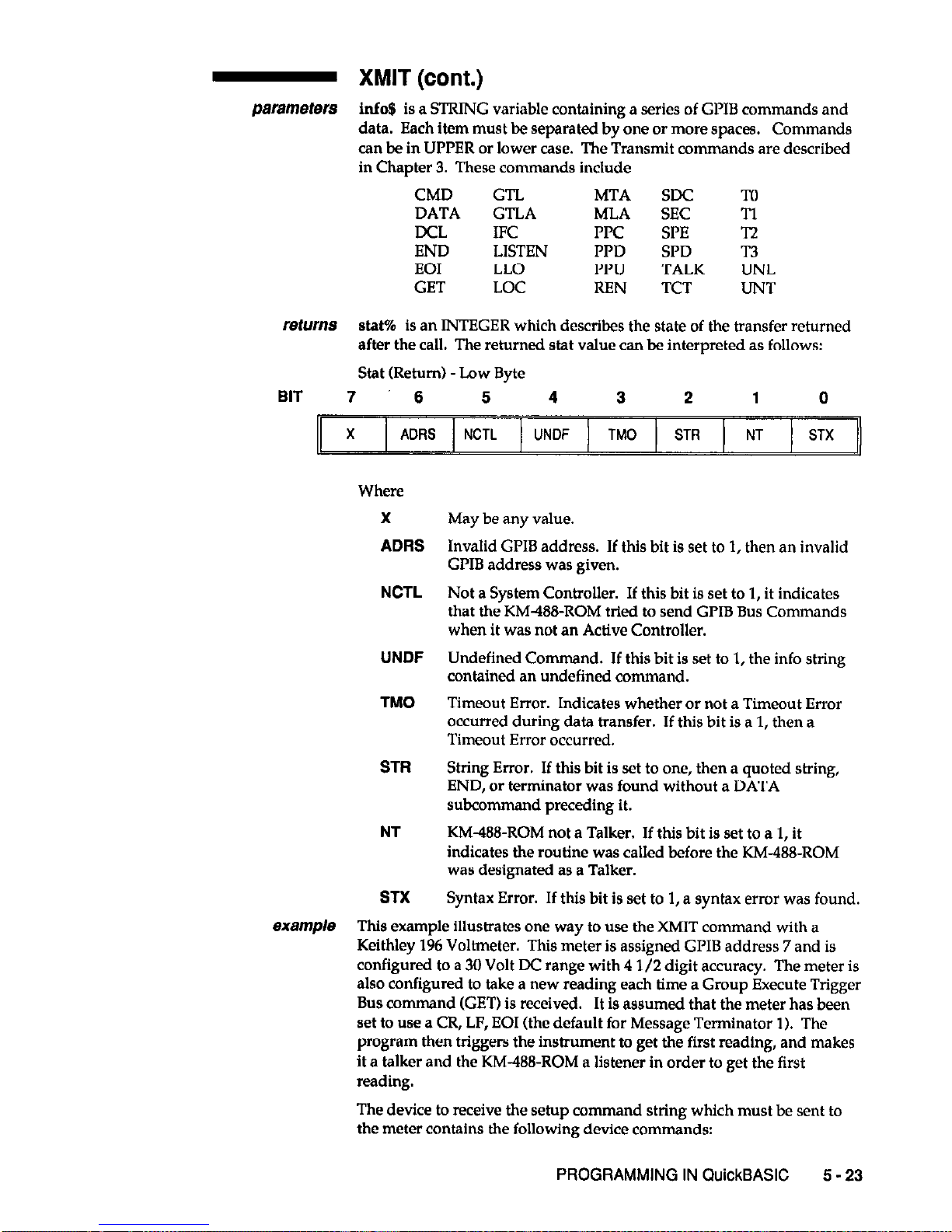
- XMIT (cont.)
parameters Info.9 is a STRING variable containing a series of GPIB commands and
data. Each item must be separated by one or more spaces.
Commands
can be in UPPER or lower case. The Transmit commands are described
in Chapter 3. These comman
ds include
CMD GTL MTA SDC To
DATA
GTLA
MLA SEC Tl
DCL IFC FTC WE Tz
END LISTEN
PPD
SPD T3
EOI LLO PPU
TALK UNL
GET LOC REN TCT UNT
returns
stat% is an INTEGER which describes the state of the transfer returned
after the call. The returned stat value can be interpreted as follows:
Stat (Return) -Low Byte
BIT 7 6
5
4 3
2
1 0
X ADRS NCTL UNDF TM0 STR NT STX
X
ADRS
May be any value.
NCTL
Invalid GPIB address. If this bit is set to 1, then an invalid
GPIB address was given.
Not a System Controller.
If this bit is set to 1, it indicates
that the KM488-ROM tried to send GPIB Bus Commands
when it was not an Active Controller.
UNDF
Undefined Command. If this bit is set to 1, the info string
contained an undefined command.
TM0
Timeout Error. Indicates whether or not a Timeout Error
occurred during data transfer. If this bit is a 1, then a
Timeout Error occurred.
STR
String Error. If this bit is set to one, then a quoted string,
END, or terminator was found without a DATA
subcommand preceding it.
NT KM-488-ROM not a Talker. If this bit is set to a 1, it
indicates the routine was called before the KM-488-ROM
was designated as a Talker.
STX Syntax Error. If this bit is set to 1, a syntax error was found.
This example illustrates one way to use the XMIT command with a
Keithley 196 Voltmeter. This meter is assigned GPIB address 7 and is
configured to a 30 Volt DC
range
with 4 l/2 digit accuracy. The meter is
also configured to take a new reading each time a Group Execute Trigger
Bus command (GET) is received.
It is assumed that the meter has been
set to use a CR, LF, EOI (the default for Message Terminator 1). The
program then triggers the instrument to get the first reading, and makes
it a talker and the KM-488-ROM a listener in order to get the first
reading.
The device to receive the setup command string which must be sent to
the meter contains the following device commands:
PROGRAMMING IN QuickBASIC
5 - 23
Page 94
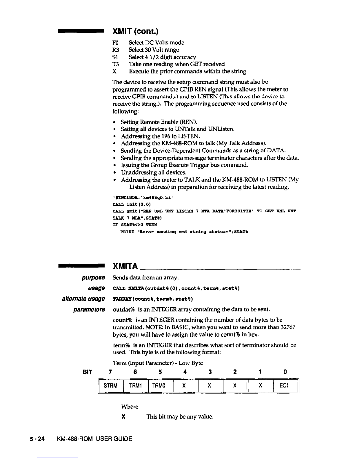
XMIT (cont.)
FO Select DC Volts mode
R3 Select 30 Volt range
Sl Select 4 l/2 digit accuracy
T3
Take one reading when GET received
X
Execute the prior commands within the string
The device to receive the setup command string must also be
programmed to assert the GPIB REN signal (This allows the meter to
receive GLIB commands.) and to LISTEN (This allows the device to
receive the string.). The programming sequence used consists of the
following:
l
Setting Remote Enable (REN).
l
Setting all devices to UNTalk and UNListen.
l
Addressing the 196 to LISTEN.
l
Addressing the KM&&&ROM to talk (My Talk Address).
l
Sending the Device-Dependent Commands as a string of DATA.
l
Sending the appropriate message terminator characters after the data.
l
Issuing the Group Execute Trigger bus command.
l
Unaddressing all devices.
l
Addressing the meter to TALK and the KM-488-ROM to LISTEN (My
Listen Address) in preparation for receiving the latest reading.
- XMITA
purpose Sends data from an array.
usage
CALL lMITA(out&t%(O),aount%,tom%,~tat%)
alternate usage
TARRAY(acmnt%,tsrm%,~tat%)
parametsrs
outdat% is an INTEGER array containing the data to be sent.
count% is an INTEGER containing the number of data bytes to be
transmitted. NOTE: In BASIC, when you want to send more than 32767
bytes, you will have to assign the value to count% in hex.
term% is an INTEGER that describes what sort of terminator should be
used. This byte is of the following format:
Term (Input Parameter) -Low Byte
BIT 7
6
5
4 3
2 1
0
STRM
TRMl
TRMO X
X EOI
Where
X This bit may be any value.
5-24 KM-4%ROM USER GUIDE
Page 95
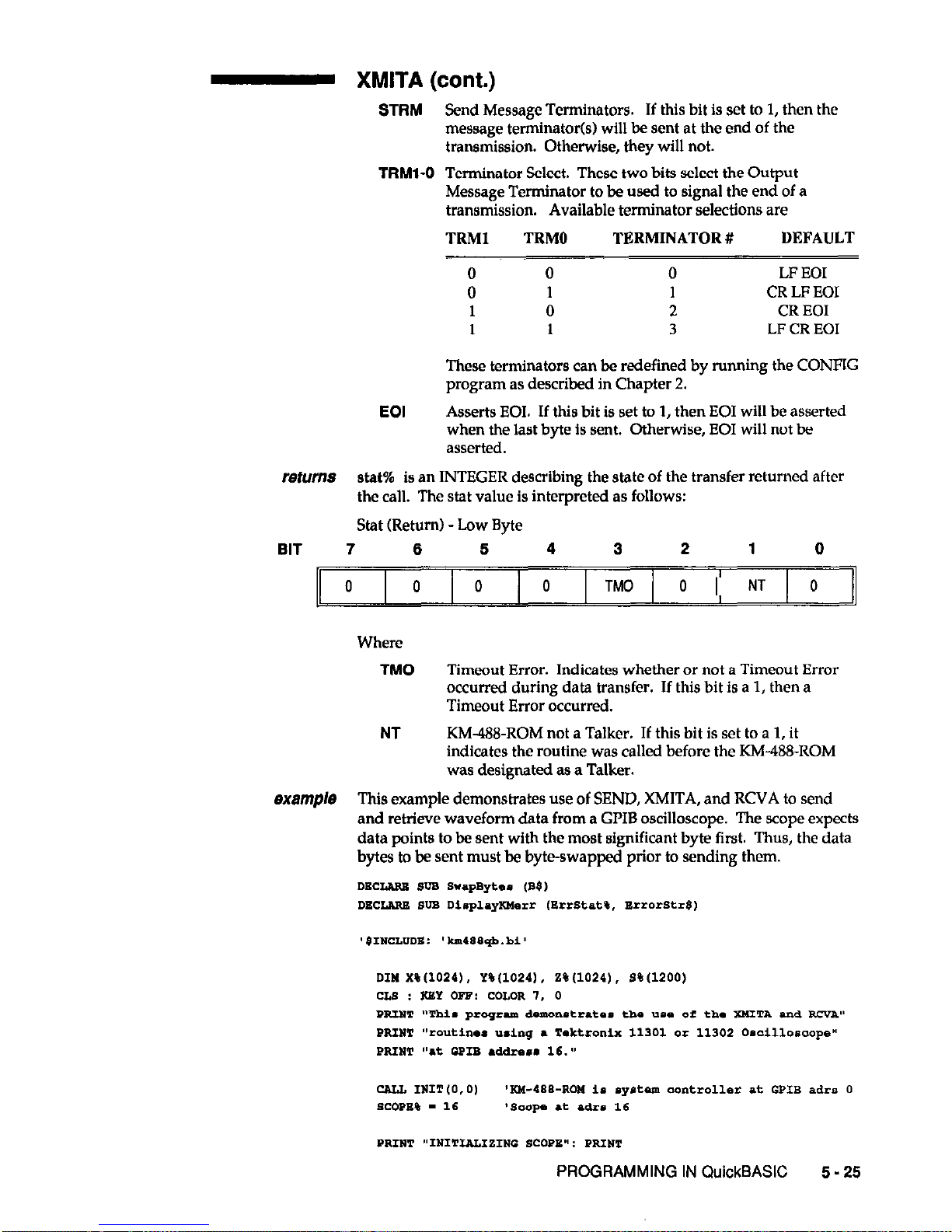
XMITA (cont.)
STRM Send Message Terminators. If this bit is set to 1, then the
message terminator(s) will be sent at the end of the
transmission. Otherwise, they will not.
TRMl-0 Terminator Select. These two bits select the Output
Message Terminator to be used to signal the end of a
transmission. Available terminator selections are
TRMI TRMO TERMINATOR #
DEFAULT
0
0 0
LF EOI
0
1 1 CR LF EOI
1 0
2
CR EOI
1
1
3
LF CR EOI
These terminators can be redefined by running the CONFIG
program as described in Chapter 2.
EOI
Asserts EOI. If this bit is set to 1, then EOI will be asserted
when the last byte is sent. Otherwise, EOI will not be
asserted.
returns
stat% is an INTEGER describing the state of the transfer returned after
the call. The stat value is interpreted as follows:
Stat (Return) - Low Byte
BIT 7 6 6
4
3
2
1
0
Where
TM0
Timeout Error. Indicates whether or not a Timeout Error
occurred during data transfer. If this bit is a 1, then a
Timeout Error occurred.
NT
KM-488-ROM not a Talker. If this bit is set to a 1, it
indicates the routine was called before the KM-488-ROM
was designated as a Talker.
example This example demonstrates use of SEND, XMITA, and RCVA to send
and retrieve waveform data from a GPIB oscilloscope. The scope expects
data points to be sent with the most significant byte first. Thus, the data
bytes to be sent must be byte-swapped prior to sending them.
DSCLARB SW s*e.payt~~ (88)
DSCLAm 80s Di.playmerr mxSt.e.t.%, srrorstr*,
DIM X%WZO, Y%(1024), 2%(1024), S%WOO)
CLS : RBY on: coI,oa 7, 0
CaLI, INIT10,O) 'KM-488-ROH ia system oontroller nt OPIB ndrs 0
SCOPBP - 16
‘Saope l t a&x 16
PaINT ‘~Tlln?cArJZTNO SCOPP”: PaINT
PROGRAMMING IN QuickBASIC
5-25
Page 96

- XMITA (cont.)
5-26 KM-488-ROM USER GUlDE
Page 97

XMITA (cont.)
cm8 =
“EICDG w*m : BIWARY”
CALL SmD(SCGPB%, me, BmG%)
IB (HAG% 0 0, TEEN CALL Di~playm4errLFLaG%, CUDS)
am6 =
"OOTPDT mm."
CALL sBND,SCOPE%, aAD*, BL?.G%)
TB (SLAG0 <> 0) THBN CALL Di‘pl*yIG4err@wbG%, cMD$)
CMD8 -
"CVRVE 1" 'Ask for d*ta to be returned
CALL ssND,SCOPB%, aloe, BLaG%,
IB (mAG% <> 0) TERN c?ALL DispPdymerr,yIAG%, Cl.m$)
CnDg = "lY.m 'I + STRB,SCOPS%, + aa PaA"
CALL xt4Ir(cMD6, mAG%,
'setup for saope to send data
IF (BxAG% <> 0) lwzN CALL DiaplaylQberr,BLAG%, adD$)
CGrmT%=7: IA-0
CGrmTP - 2050:
L% = 0
CALL RcvA(s%(ol, comT6, 0, 1%. SLAG%) 'D.tA reaeivec3
10 WAG% 0 0) TBBN CAL& Di.splayIWerr(BIAG%, CMO$)
IF L% <> (2 + N”KRW% l 2) TRE” GOT0 2080
FOR 1% = 1 TO 1024
se = -8 (9% (1%) I
CAT& sr.pRyts. (MS)
Y%(l% - 1) = vAL(E@)
IP x%(1% - 1) - %(I% - 1) TEE" PRINT ".": ELSE PRINT I'*";
mm 1%
PROGRAMMING IN QuickBASIC 5-27
Page 98

- XMITA (cont.)
PRINT
888P% = 0
CALL SPOLL(BCGPE%, PaSP%, mAG%)
PRINT “SPOLL. = “;
HBx$,RBSP% AND 255,
1% = LE”,B$)
IB 1% - 1 TED%" B$ - "000" + B$
IB 1% = 2 TBXN B$ = "00" + B$
TB I.% = 3 THEN B$ = "0" + B$
LSS$ = RIGer$(s$, 2)
Ksae = =wf$(B$. 2)
se = "LB" + LSB$ + WBS 'hap bytes
5-20 KM-488-ROM USER GUIDE
Page 99

Chapter 6
PROGRAMMING IN TURBO PASCAL
While Chapter 3 gives a brief overview of the routines available for programming the KM48SROM, this chapter gives instructions for calling the routines from TURBO PASCAL. The
routines appear in alphabetical order and include a sample program for each.
6.1 GENERAL
TURBO PASCAL direct support is currently offered for versions 4.0 and 5.0. The interface for
TURBO PASCAL includes four different files, as follows:
KM488PAS.TPU “UNIT” file for use with Borland TURBO PASCAL version 5.0.
KM488P4.TPU “UNIT’ file for use with Borland TURBO PASCAL version 4.0.
KM488PASPAS Source file to be used for m-building TURBO Pascal “UNfT” file.
KM488PAS.OBJ Object code file to be used for re-building TURBO Pascal “UNIT” file.
The files KM488PASPAS and KM488I’LB.OBJ can be used to create a new “unit” file should
you need to.
Supported Versions
The Envtronment
Turbo PASCAL versions 4.0,5.0 and higher.
Before you begin to develop programs in TURBO PASCAL,
several files must be present in your working directory. Copy
the appropriate files from the KM48EROM Disks to your
working directory:
TURBO PASCAL 4.0 TURBO PASCAL 5.0
\turbopas~488p4.tpu IntrbopasUtm488pas.tpu
NOTE: km488p4.pas must be renamed km488pas.tpu.
File Header
Compiling
Software
-
Your application program can be compiled in the usual fashion.
Be sure to include the following line in your program:
USES hm6pas;
The KM-488-ROM firmware contains a number of configuration
parameters which govern the default settings of the input and
output message terminator settings, message timeout periods,
PROGRAMMING IN TURBO PASCAL 6 - 1
Page 100
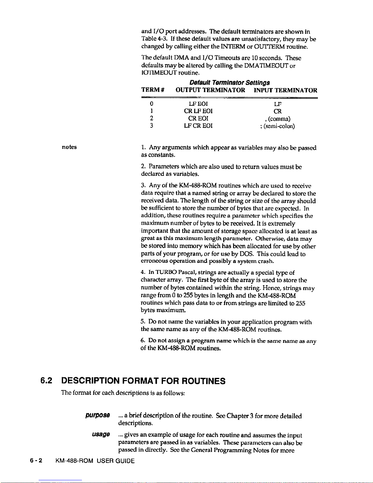
and I/O port addresses. The default terminators are shown in
Table 4-3. If these default values are unsatisfactory, they may be
changed by calling either the INTERM or OUTTERM routine.
The default DMA and I/O Timeouts are 10 seconds. These
defaults may be altered by calling the DMATIMEOUT or
IOTIMEOUT routine.
Default Termlnator Settings
TERM # OUTPUT TERMINATOR INPUT TERMINATOR
0
LF EOI
LF
1 CR LF’ EOI
CR
2
CR EOI , (comma)
3
LF CR EOI
: (semi-colon)
1. Any arguments which appear as variables may also be passed
as constants.
2. Parameters which are also used to return values must be
declared as variables.
3. Any of the KM4WROM routines which are used to receive
data require that a named string or array be declared to store the
received data. The length of the string or size of the array should
be sufficient to store the number of bytes that are expected. In
addition, these routines require a parameter which specifies the
maximum number of bytes to be received. It is extremely
important that the amount of storage space allocated is at least as
great as this maximum length parameter. Otherwise, data may
be stored into memory which has been allocated for use by other
parts of your program, or for use by DOS. This could lead to
erroneous operation and possibly a system crash.
4. In TURBO Pascal, strings are actually a special type of
character array. The first byte of the array is used to store the
number of bytes contained within the string. Hence, strings may
range from 0 to 255 bytes in length and the KM&B-ROM
routines which pass data to or from strings are limited to 255
bytes maximum.
5. Do not name the variables in your application program with
the same name as any of the KM&?&ROM routines.
6. Do not assign a program name which is the same name as any
of the KM-48&ROM routines.
6.2 DESCRIPTION FORMAT FOR ROUTINES
The format for each descriptions is as follows:
purpose a brief description of the routine. See Chapter 3 for more detailed
descriptions.
usage
. gives an example of usage for each routine and assumes the input
parameters are passed in as variables. These parameters can also be
passed in directly. See the General Programming Notes for more
6-2
KM-488~ROM USER GUIDE
 Loading...