

Page 1

Model 6514 System Electrometer
Instruction Manual
A GREATER MEASURE OF CONFIDENCE
Test Equipment Depot - 800.517.8431 - 99 Washington Street Melrose, MA 02176 - TestEquipmentDepot.com
Page 2

WARRANTY
Keithley Instruments, Inc. warrants this product to be free from defects in material and w
period of 1 year from date of shipment.
Keithley Instruments, Inc. warrants the following items for 90 days from the date of shipment: probes, cables,
rechargeable batteries, diskettes, and documentation.
During the warranty period, we will, at our option, either repair or replace any product that proves to be defective.
To exercise this warranty, write or call your local Keithley representative, or contact Keithley headquarters in
Cleveland, Ohio. You will be given prompt assistance and return instructions. Send the product, transportation
prepaid, to the indicated service facility. Repairs will be made and the product returned, transportation prepaid.
Repaired or replaced products are warranted for the balance of the original warranty period, or at least 90 days.
LIMIT A TION OF W
This warranty does not apply to defects resulting from product modification without Keithle
consent, or misuse of any product or part. This warranty also does not apply to fuses, software, non-rechargeable
batteries, damage from battery leakage, or problems arising from normal wear or failure to follow instructions.
THIS WARRANTY IS IN LIEU OF ALL OTHER WARRANTIES, EXPRESSED OR IMPLIED, INCLUDING ANY IMPLIED WARRANTY OF MERCHANTABILITY OR FITNESS FOR A PARTICULAR USE.
THE REMEDIES PROVIDED HEREIN ARE BUYER’S SOLE AND EXCLUSIVE REMEDIES.
NEITHER KEITHLEY INSTRUMENTS, INC. NOR ANY OF ITS EMPLOYEES SHALL BE LIABLE FOR
ANY DIRECT, INDIRECT, SPECIAL, INCIDENTAL OR CONSEQUENTIAL DAMAGES ARISING OUT OF
THE USE OF ITS INSTRUMENTS AND SOFTWARE EVEN IF KEITHLEY INSTRUMENTS, INC., HAS
BEEN ADVISED IN ADVANCE OF THE POSSIBILITY OF SUCH DAMAGES. SUCH EXCLUDED DAMAGES SHALL INCLUDE, BUT ARE NOT LIMITED TO: COSTS OF REMOVAL AND INSTALLATION,
LOSSES SUSTAINED AS THE RESULT OF INJURY TO ANY PERSON, OR DAMAGE TO PROPERTY.
ARRANTY
orkmanship for a
y’s express written
A G R E A
T E R M E A S U R E O F C O N F I D E N C E
Keithley Instruments, Inc.
3/04
Page 3

Model 6514 System Electrometer
Instruction Manual
©1998, Keithley Instruments, Inc.
All rights reserved.
Cleveland, Ohio, U.S.A.
Fourth Printing, May 2003
Document Number: 6514-901-01 Rev
. D
Page 4

Manual Print History
The print history shown below lists the printing dates of all Revisions and Addenda created
for this manual. The Revision Level letter increases alphabetically as the manual undergoes
subsequent updates. Addenda, which are released between Revisions, contain important change
information that the user should incorporate immediately into the manual. Addenda are
numbered sequentially. When a new Revision is created, all Addenda associated with the
previous Revision of the manual are incorporated into the new Revision of the manual. Each
new Revision includes a revised copy of this print history page.
Revision A (Document Number 6514-901-01)
Addendum A (Document Number 6514-901-02).....................................................December 1998
Revision B (Document Number 6514-901-01) ........................................................ December 1998
Revision C (Document Number 6514-901-01) ................................................................. June 1999
Revision D (Document Number 6514-901-01)................................................................. May 2003
............................................................October 1998
All Keithley product names are trademarks or registered trademarks of Keithley Instruments, Inc.
Other brand names are trademarks or registered trademarks of their respective holders.
Page 5

S
afety Precautions
The following safety precautions should be observed before using this product and an
some instruments and accessories would normally be used with non-hazardous voltages, there are situations where hazardous
conditions may be present.
This product is intended for use by qualified personnel who recognize shock hazards and are familiar with the safety precautions
required to avoid possible injury. Read and follow all installation, operation, and maintenance information carefully before using the product. Refer to the manual for complete product specifications
If the product is used in a manner not specified, the protection pr vided by the product may be impaired.
The types of product users are:
Responsible body is the individual or group responsible for the use and maintenance of equipment, for ensuring that the equip-
ment is operated within its specifications and operating limits, and for ensuring that operators are adequately trained
Operators use the product for its intended function. They must be trained in electrical safety procedures and proper use of the
instrument. They must be protected from electric shock and contact with hazardous live circuits.
Maintenance personnel perform routine procedures on the product to keep it operating properly, for example, setting the line
voltage or replacing consumable materials. Maintenance procedures are described in the manual. The procedures explicitly state
if the operator may perform them. Otherwise, they should be performed only by service personnel.
Service personnel are trained to work on live circuits, and perform safe installations and repairs of products. Only properly
trained service personnel may perform installation and service procedures.
Keithley products are designed for use with electrical signals that are rated Measurement Category I and Measurement Category
II, as described in the International Electrotechnical Commission (IEC) Standard IEC 60664. Most measurement, control, and
data I/O signals are Measurement Category I and must not be directly connected to mains voltage or to voltage sources with
high transient over-voltages. Measurement Category II connections require protection for high transient over-voltages often
associated with local AC mains connections. Assume all measurement, control, and data I/O connections are for connection to
Category I sources unless otherwise marked or described in the Manual.
Exercise extreme caution when a shock hazard is present. Lethal voltage may be present on cable connector jacks or test fixture .
The American National Standards Institute (ANSI) states that a shock hazard exists when voltage levels greater than 30V RMS,
42.4V peak, or 60VDC are present. A good safety practice is to expect that hazardous voltage is present in any unknown
circuit before measuring.
Operators of this product must be protected from electric shock at all times. The responsible body must ensure that operators
are prevented access and/or insulated from every connection point. In some cases, connections must be exposed to potential
human contact. Product operators in these circumstances must be trained to protect themselves from the risk of electric shock.
If the circuit is capable of operating at or above 1000 volts, no conductive part of the circuit may be exposed.
Do not connect switching cards directly to unlimited power circuits. They are intended to be used with impedance limited
sources. NEVER connect switching cards directly to AC mains. When connecting sources to switching cards, install protective
devices to limit fault current and voltage to the card.
Before operating an instrument, make sure the line cord is connected to a properly grounded power receptacle. Inspect the
connecting cables, test leads, and jumpers for possible wear, cracks, or breaks before each use.
When installing equipment where access to the main power cord is restricted, such as rack mounting, a separate main input
power disconnect device must be provided, in close proximity to the equipment and within easy reach of the operator.
For maximum safety, do not touch the product, test cables, or any other instruments while power is applied to the circuit under
test. ALWAYS remove power from the entire test system and discharge any capacitors before: connecting or disconnecting
y associated instrumentation. Although
5/03
Page 6
cables or jumpers, installing or removing switching cards, or making internal changes, such as installing or removing jumpers.
Do not touch any object that could provide a current path to the common side of the circuit under test or power line (earth) ground.
Always make measurements with dry hands while standing on a dry, insulated surface capable of withstanding the voltage being
measured.
The instrument and accessories must be used in accordance with its specifications and operating instructions or the safety of the
equipment may be impaired.
Do not exceed the maximum signal levels of the instruments and accessories, as defined in the specifications and operating
information, and as shown on the instrument or test fixture panels, or switching card
When fuses are used in a product, replace with same type and rating for continued protection against fire hazard
Chassis connections must only be used as shield connections for measuring circuits, NOT as safety earth ground connections.
If you are using a test fixture, keep the lid closed while power is applied to the device under test. Safe operation requires the use
of a lid interlock.
If a screw is present, connect it to safety earth ground using the wire recommended in the user documentation.
!
The symbol on an instrument indicates that the user should refer to the operating instructions located in the manual.
The symbol on an instrument shows that it can source or measure 1000 volts or more, including the combined effect of
normal and common mode voltages. Use standard safety precautions to avoid personal contact with these voltages.
The symbol indicates a connection terminal to the equipment frame.
The
WARNING
information very carefully before performing the indicated procedure.
The
CAUTION
warranty.
Instrumentation and accessories shall not be connected to humans.
Before performing any maintenance, disconnect the line cord and all test cables.
To maintain protection from electric shock and fire, replacement components in mains circuits, including the power transformer,
test leads, and input jacks, must be purchased from Keithley Instruments. Standard fuses, with applicable national safety
approvals, may be used if the rating and type are the same. Other components that are not safety related may be purchased from
other suppliers as long as they are equivalent to the original component. (Note that selected parts should be purchased only
through Keithley Instruments to maintain accuracy and functionality of the product.) If you are unsure about the applicability
of a replacement component, call a Keithley Instruments office for information
To clean an instrument, use a damp cloth or mild, water based cleaner. Clean the exterior of the instrument only. Do not apply
cleaner directly to the instrument or allow liquids to enter or spill on the instrument. Products that consist of a circuit board with
no case or chassis (e.g., data acquisition board for installation into a computer) should never require cleaning if handled according to instructions. If the board becomes contaminated and operation is affected, the board should be returned to the factory for
proper cleaning/servicing.
heading in a manual explains dangers that might result in personal injury or death. Always read the associated
heading in a manual explains hazards that could damage the instrument. Such damage may invalidate the
Page 7

Table of Contents
1 Getting Started
General information ................................................................... 1-2
Warranty information .......................................................... 1-2
Contact information ............................................................ 1-2
Safety symbols and terms ................................................... 1-2
Inspection ............................................................................ 1-2
Options and accessories ...................................................... 1-3
System electrometer features ..................................................... 1-4
Front and rear panel familiarization ........................................... 1-5
Front panel summary .......................................................... 1-5
Rear panel summary ........................................................... 1-8
Power-up .................................................................................. 1-10
Line power connection ...................................................... 1-10
Line frequency selection ................................................... 1-10
Power-up sequence ........................................................... 1-11
Display ..................................................................................... 1-12
Status and error messages ................................................. 1-12
Default settings ......................................................................... 1-12
SCPI programming .................................................................. 1-15
2 Measurement Concepts
Measurement overview .............................................................. 2-2
Performance considerations ....................................................... 2-2
Warm-up period .................................................................. 2-2
Autozero .............................................................................. 2-2
Connection fundamentals ........................................................... 2-3
Input connector ................................................................... 2-3
Low noise input cables ........................................................ 2-5
Basic connections to DUT .................................................. 2-6
Test fixture .......................................................................... 2-9
Input protection ................................................................. 2-11
Floating measurements ..................................................... 2-11
Zero check and zero correct ..................................................... 2-13
Zero check ......................................................................... 2-13
Zero correct ....................................................................... 2-14
SCPI programming — zero check and zero correct ......... 2-15
Input bias current and offset voltage calibration ...................... 2-17
Front panel ........................................................................ 2-17
SCPI programming ........................................................... 2-18
Measurement considerations .................................................... 2-19
Page 8

3Volts and Ohms Measurements
Measurement overview ............................................................... 3-2
Guarding ..................................................................................... 3-2
Test circuit leakage .............................................................. 3-2
Input cable leakage and capacitance ................................... 3-3
Volts and ohms measurement procedure .................................... 3-4
V-Drop and I-Source for ohms ............................................ 3-6
SCPI programming ..................................................................... 3-7
Programming example ........................................................ 3-8
Volts and ohms measurement considerations ............................. 3-9
Loading effects .................................................................... 3-9
Cable leakage resistance ...................................................... 3-9
Input capacitance (settling time) ....................................... 3-10
Guarding input cable ......................................................... 3-12
Application ............................................................................... 3-14
Capacitor dielectric absorption .......................................... 3-14
4 Amps Measurements
Measurement overview ............................................................... 4-2
Amps measurement procedure ................................................... 4-2
Damping .............................................................................. 4-4
High impedance measurement techniques ................................. 4-5
SCPI programming ..................................................................... 4-8
Programming example ........................................................ 4-9
Amps measurement considerations ............................................ 4-9
Input bias current ................................................................. 4-9
Voltage burden ..................................................................... 4-9
Noise .................................................................................. 4-10
Applications .............................................................................. 4-13
Diode leakage current ........................................................ 4-13
Capacitor leakage current .................................................. 4-14
Cable insulation resistance ................................................ 4-14
Surface insulation resistance (SIR) ................................... 4-15
5 Coulombs Measurements
Measurement overview ............................................................... 5-2
Auto discharge ............................................................................ 5-2
Coulombs measurement procedure ............................................ 5-3
SCPI programming ..................................................................... 5-5
Programming example ........................................................ 5-6
Coulombs measurement considerations ..................................... 5-6
Input bias current ................................................................. 5-6
External voltage source ....................................................... 5-6
Zero check hop and auto discharge hop .............................. 5-7
Application ................................................................................. 5-7
Capacitance measurements ................................................. 5-7
Page 9

6 Range, Units, Digits, Rate, and Filters
Range, units, and digits .............................................................. 6-2
Range .................................................................................. 6-2
Units .................................................................................... 6-4
Digits ................................................................................... 6-4
SCPI programming - range and digits ................................ 6-4
Rate ............................................................................................ 6-6
SCPI programming — rate ................................................. 6-7
Filters ......................................................................................... 6-8
Median filter ........................................................................ 6-8
Digital filter ......................................................................... 6-9
SCPI programming — filters ............................................ 6-10
7 Relative, mX+b and Percent (%)
Relative ....................................................................................... 7-2
Setting and controlling relative ........................................... 7-2
SCPI programming — relative ........................................... 7-3
mX+b and percent (%) ............................................................... 7-4
mX+b .................................................................................. 7-4
Percent (%) .......................................................................... 7-5
SCPI programming — mX+b and percent ......................... 7-6
8 Buffer
Buffer operations ........................................................................ 8-2
Store .................................................................................... 8-2
Recall .................................................................................. 8-2
Buffer statistics ................................................................... 8-3
SCPI programming .................................................................... 8-4
Programming example......................................................... 8-6
9Triggering
Trigger models ........................................................................... 9-2
Idle and initiate ................................................................... 9-4
Trigger model operation ...................................................... 9-4
Trigger model configuration — front panel ........................ 9-7
SCPI programming ..................................................................... 9-9
Programming example ...................................................... 9-10
External triggering ................................................................... 9-11
Input trigger requirements ................................................. 9-11
Output trigger specifications ............................................. 9-12
External trigger example ................................................... 9-12
Page 10

10 Limit T ests
Limit testing .............................................................................. 10-2
Binning ..................................................................................... 10-4
Component handler interface ............................................ 10-6
Component handler types .................................................. 10-7
Digital output clear pattern ................................................ 10-8
Front panel operation .............................................................. 10-10
Limit test configuration ................................................... 10-10
Perform limit tests ........................................................... 10-11
SCPI programming ................................................................. 10-12
Programming example .................................................... 10-15
11 Digital I/O, Analog Outputs, and External Feedback
Digital I/O port ......................................................................... 11-2
Sink mode — controlling external devices ....................... 11-3
Source mode — logic control ............................................ 11-5
Setting digital output lines ................................................. 11-5
SCPI programming — digital output pattern .................... 11-6
Analog outputs .......................................................................... 11-7
2V analog output ............................................................... 11-7
External feedback ................................................................... 11-11
Electrometer input circuitry ............................................ 11-11
Shielded fixture construction ........................................... 11-12
Non-standard coulombs ranges ....................................... 11-13
External feedback procedure ........................................... 11-13
Logarithmic currents ....................................................... 11-15
Non-decade current gains ................................................ 11-16
SCPI programming — external feedback ....................... 11-17
12 Remote Operation
Selecting and configuring an inter ace ..................................... 12-2
Interfaces ........................................................................... 12-2
Languages .......................................................................... 12-2
Interface selection and configuration procedures .............. 12-2
GPIB operation and reference .................................................. 12-5
GPIB bus standards ........................................................... 12-5
GPIB bus connections ....................................................... 12-5
Primary address selection .................................................. 12-7
General bus commands ..................................................... 12-8
Front panel GPIB operation ............................................ 12-10
Programming syntax ....................................................... 12-11
RS-232 interface reference ..................................................... 12-17
Sending and receiving data .............................................. 12-17
RS-232 settings ............................................................... 12-17
RS-232 connections ......................................................... 12-18
Error messages ................................................................ 12-19
Page 11

13 Status Structure
Overview .................................................................................. 13-2
Clearing registers and queues ................................................... 13-4
Programming and reading registers ......................................... 13-5
Programming enable registers ........................................... 13-5
Reading registers ............................................................... 13-6
Status byte and service request (SRQ) ..................................... 13-7
Status byte register ............................................................ 13-7
Service request enable register .......................................... 13-8
Serial polling and SRQ ..................................................... 13-9
Status byte and service request commands ....................... 13-9
Status register sets .................................................................. 13-11
Register bit descriptions .................................................. 13-11
Condition registers .......................................................... 13-15
Event registers ................................................................. 13-16
Event enable registers ..................................................... 13-17
Queues .................................................................................... 13-18
Output queue ................................................................... 13-18
Error queue ...................................................................... 13-19
14 Common Commands
15 SCPI Signal Oriented Measurement Commands
16 DISPlay , FORMat, and SYSTem
DISPlay subsystem .................................................................. 16-2
FORMat subsystem .................................................................. 16-4
SYSTem subsystem .................................................................. 16-8
17 SCPI Reference T ables
General notes ............................................................................ 17-2
18 Performance V erification
Introduction .............................................................................. 18-2
Verification test requirements ................................................... 18-3
Environmental conditions ................................................. 18-3
Warm-up period ................................................................ 18-3
Line power ........................................................................ 18-3
Recommended test equipment ................................................. 18-4
Verification limits ..................................................................... 18-6
Example reading limits calculation ................................... 18-6
Recalculating resistance reading limits ............................. 18-6
Calibrator voltage calculations ................................................. 18-7
Current calculations .......................................................... 18-7
Charge calculations ........................................................... 18-7
Page 12

Performing the verification test procedures .............................. 18-8
Test summary .................................................................... 18-8
Test considerations ............................................................ 18-8
Restoring factory defaults ......................................................... 18-9
Input bias current and offset voltage calibration ...................... 18-9
Offset voltage calibration .................................................. 18-9
Input bias current calibration ............................................. 18-9
Volts measurement accuracy .................................................. 18-10
Amps measurement accuracy ................................................. 18-12
20µA-20mA range accuracy ........................................... 18-12
20pA-2µA range accuracy .............................................. 18-13
Ohms measurement accuracy ................................................. 18-15
Ω
-20MΩ range accuracy ............................................. 18-15
2k
200MΩ-200GΩ range accuracy ...................................... 18-17
Coulombs measurement accuracy .......................................... 18-18
19 Calibration
Introduction .............................................................................. 19-2
Environmental conditions ......................................................... 19-2
Temperature and relative humidity..................................... 19-2
Warm-up period ................................................................. 19-2
Line power ......................................................................... 19-2
Calibration considerations ........................................................ 19-3
Calibration cycle ................................................................ 19-3
Recommended calibration equipment ...................................... 19-3
Calibration errors ...................................................................... 19-5
Calibration menu ...................................................................... 19-5
Aborting calibration .................................................................. 19-5
Current and charge calculations ............................................... 19-6
Manual calculations............................................................ 19-6
Automatic calculations ...................................................... 19-6
Calibration procedure ............................................................... 19-7
Preparing for calibration .................................................... 19-7
Input bias current and offset voltage calibration ............... 19-7
Volts calibration ................................................................. 19-8
Amps calibration ............................................................. 19-10
Coulombs calibration ...................................................... 19-14
Ohms calibration ............................................................. 19-16
Entering calibration dates and saving calibration ............ 19-18
Locking out calibration ................................................... 19-18
Changing the calibration code ................................................ 19-18
Resetting the calibration code ................................................ 19-19
Displaying calibration dates ................................................... 19-19
Displaying the calibration count ............................................. 19-20
Page 13

20 Routine Maintenance
Introduction .............................................................................. 20-2
Setting line voltage and replacing line fuse ............................. 20-2
Front panel tests ................................................................ 20-4
DISP test ........................................................................... 20-4
KEY test ............................................................................ 20-4
A Specifications
B Status and Error Messages
C General Measurement Considerations
Measurement considerations ..................................................... C-2
Ground loops ...................................................................... C-2
Triboelectric effects ........................................................... C-3
Piezoelectric and stored charge effects .............................. C-3
Electrochemical effects ...................................................... C-4
Humidity ............................................................................ C-4
Light ................................................................................... C-4
Electrostatic interference ................................................... C-4
Magnetic fields ................................................................... C-5
Electromagnetic Interference (EMI) .................................. C-5
D DDC Emulation Commands
DDC language ........................................................................... D-2
E Example Programs
Programming examples .............................................................. E-2
Changing function and range .............................................. E-2
One-shot triggering ............................................................. E-3
Generating SRQ on buffer full ............................................ E-4
Storing readings in buffer ................................................... E-5
Taking readings using the :READ? command .................... E-6
Controlling the Model 6514 via the RS-232 COM2 port ... E-7
Page 14

F IEEE-488 Bus Overview
Introduction ............................................................................... F-2
Bus description .......................................................................... F-3
Bus lines .................................................................................... F-5
Data lines ............................................................................ F-5
Bus management lines ........................................................ F-5
Handshake lines .................................................................. F-6
Bus commands ........................................................................... F-7
Uniline commands .............................................................. F-8
Universal multiline commands ........................................... F-8
Addressed multiline commands ......................................... F-9
Address commands ............................................................ F-9
Unaddress commands ......................................................... F-9
Common commands ......................................................... F-10
SCPI commands ............................................................... F-10
Command codes ............................................................... F-10
Typical command sequences ............................................ F-11
IEEE command groups ..................................................... F-12
Interface function codes .......................................................... F-13
G IEEE-488 and SCPI Conformance Information
Introduction ............................................................................... G-2
H Calibration Options
Introduction ............................................................................... H-2
Reading calibration standard values .......................................... H-2
Data transfer connections ................................................... H-2
Reading values ................................................................... H-2
Example program ............................................................... H-3
Remote calibration ..................................................................... H-4
Calibration commands ........................................................ H-4
Remote calibration overview .............................................. H-4
Page 15

List of Illustrations
1 Getting Started
Figure 1-1 Model 6514 front panel .......................................................... 1-5
Figure 1-2 Model 6514 rear panel ........................................................... 1-8
2 Measurement Concepts
Figure 2-1 Input connector configurations .............................................. 2-4
Figure 2-2 Maximum input levels ........................................................... 2-5
Figure 2-3 Basic connections for unguarded measurements ................... 2-6
Figure 2-4 Shielding for unguarded measurements ................................. 2-7
Figure 2-5 Basic connections for guarded measurements ....................... 2-8
Figure 2-6 General purpose test fixture ................................................... 2-9
Figure 2-7 Capacitor test circuit without protection .............................. 2-11
Figure 2-8 Capacitor test circuit with protection ................................... 2-11
Figure 2-9 Floating measurements ........................................................ 2-12
Figure 2-10 Equivalent input impedance with zero check enabled ......... 2-14
3Volts and Ohms Measurements
Figure 3-1 High-impedance voltage measurements ................................ 3-3
Figure 3-2 Connections for unguarded volts and ohms ........................... 3-5
Figure 3-3 Connections for guarded volts and ohms ............................... 3-6
Figure 3-4 Meter loading ......................................................................... 3-9
Figure 3-5 Effects of input capacitance ................................................. 3-11
Figure 3-6 Settling time ......................................................................... 3-12
Figure 3-7 Unguarded input cable ......................................................... 3-12
Figure 3-8 Guarded input cable ............................................................. 3-13
Figure 3-9 Measuring dielectric absorption ........................................... 3-15
4 Amps Measurements
Figure 4-1 Connections for amps ............................................................ 4-4
Figure 4-2 High impedance current measurements ................................. 4-5
Figure 4-3 Floating current measurements .............................................. 4-7
Figure 4-4 Voltage burden considerations ............................................. 4-10
Figure 4-5 Source resistance and capacitance ....................................... 4-11
Figure 4-6 Connections; diode leakage current test .............................. 4-13
Figure 4-7 Connections; capacitor leakage current test ......................... 4-14
Figure 4-8 Connections; cable insulation resistance test ....................... 4-14
Figure 4-9 Connections; surface insulation resistance test .................... 4-15
Page 16

5 Coulombs Measurements
Figure 5-1 Typical connections for coulombs .......................................... 5-4
Figure 5-2 Measuring capacitors ............................................................. 5-7
6 Range, Units, Digits, Rate, and Filters
Figure 6-1 Speed vs. noise characteristics ............................................... 6-6
Figure 6-2 Digital filter types; m ving and repeating .............................. 6-9
8 Buffer
Figure 8-1 Buffer locations ...................................................................... 8-3
9Triggering
Figure 9-1 Trigger model — front panel operation ................................. 9-2
Figure 9-2 Trigger model — remote operation ........................................ 9-3
Figure 9-3 Measure action block of trigger model .................................. 9-6
Figure 9-4 Trigger link connection operation ........................................ 9-11
Figure 9-5 Trigger link input pulse specifications ................................. 9-11
Figure 9-6 Trigger link output pulse specifications ............................... 9-12
Figure 9-7 DUT test system ................................................................... 9-12
Figure 9-8 Trigger link connections ....................................................... 9-13
Figure 9-9 Operation model for triggering example .............................. 9-14
10 Limit T ests
Figure 10-1 Limit tests ............................................................................. 10-2
Figure 10-2 Limit tests example .............................................................. 10-2
Figure 10-3 Operation model for limit test .............................................. 10-3
Figure 10-4 Binning system ..................................................................... 10-4
Figure 10-5 Operation model for limit testing with binning .................... 10-5
Figure 10-6 Handler interface connections .............................................. 10-6
Figure 10-7 Digital output auto-clear timing example ............................. 10-9
11 Digital I/O, Analog Outputs, and External Feedback
Figure 11-1 Digital I/O port ..................................................................... 11-2
Figure 11-2 Digital I/O port simplified schematic ................................... 11-3
Figure 11-3 Controlling externally powered relays ................................. 11-4
Figure 11-4 NAND gate control .............................................................. 11-5
Figure 11-5 Typical 2V analog output connections ................................. 11-8
Figure 11-6 Typical preamp out connections ........................................... 11-9
Figure 11-7 Electrometer input circuitry (external feedback mode) ...... 11-12
Figure 11-8 Shielded fixture construction .............................................. 11-14
Figure 11-9 “Transdiode” logarithmic current configuration ................ 11-15
Figure 11-10 Non-decade current gains ................................................... 11-16
Page 17

12 Remote Operation
Figure 12-1 IEEE-488 connector ............................................................. 12-5
Figure 12-2 IEEE-488 connections ......................................................... 12-6
Figure 12-3 IEEE-488 connector location ............................................... 12-7
Figure 12-4 RS-232 interface connector ............................................... 12-18
13 Status Structure
Figure 13-1 6514 status mode structure .................................................. 13-3
Figure 13-2 16-bit status register ............................................................. 13-6
Figure 13-3 Status byte and service request ............................................ 13-7
Figure 13-4 Standard event status .......................................................... 13-12
Figure 13-5 Operation event status ........................................................ 13-13
Figure 13-6 Measurement event status .................................................. 13-14
Figure 13-7 Questionable event status ................................................... 13-15
16 DISPlay , FORMat, and SYSTem
Figure 16-1 ASCII data format ................................................................ 16-5
Figure 16-2 IEEE-754 single precision data format (32 data bits) .......... 16-5
Figure 16-3 Key-press codes ................................................................. 16-10
18 Performance V erification
Figure 18-1 Connections for volts verification ...................................... 18-10
Figure 18-2 Connections for 20µA-20mA range verification ............... 18-12
Figure 18-3 Connections for 20pA-20µA range verification ................ 18-13
Ω
Figure 18-4 Connections for ohms verification (2
Figure 18-5 Connections for ohms verification
(200MΩ-200GΩ ranges) .............................................. 18-17
Figure 18-6 Connections for coulombs verification .............................. 18-18
-20MΩ ranges) ... 18-15
19 Calibration
Figure 19-1 Connections for volts calibration ......................................... 19-8
Figure 19-2 Connections for 20µA-20mA range calibration ................ 19-10
Figure 19-3 Connections for 20pA-2mA range calibration ................... 19-11
Figure 19-4 Connections for coulombs calibration ............................... 19-14
Figure 19-5 Connections for ohms calibration
Ω
and 2MΩ ranges) ................................................ 19-16
(2k
Figure 19-6 Connections for ohms calibration (2GΩ range) ................ 19-17
20 Routine Maintenance
Figure 20-1 Power module ...................................................................... 20-3
Page 18

C General Measurement Considerations
Figure C-1 Power line ground loops ........................................................ C-2
Figure C-2 Eliminating ground loops ...................................................... C-3
F IEEE-488 Bus Overview
Figure F-1 IEEE-488 bus configuration .................................................. F-4
Figure F-2 IEEE-488 handshake sequence ............................................. F-6
Figure F-3 Command codes .................................................................... F-8
H Calibration Options
Figure H-1 Data transfer connections ...................................................... H-2
Page 19

List of T ables
1 Getting Started
Table 1-1 SCPI commands - line frequency ........................................ 1-10
Table 1-2 Default settings .................................................................... 1-13
2 Measurement Concepts
Table 2-1 Basic measurement capabilities ............................................. 2-2
Table 2-2 SCPI commands — autozero ................................................. 2-3
Table 2-3 Display messages for zero check and zero correct .............. 2-13
Table 2-4 SCPI commands — zero check and zero correct ................. 2-15
Table 2-5 SCPI commands — input bias current and offset
Table 2-6 Summary of measurement considerations ........................... 2-19
3Volts and Ohms Measurements
Table 3-1 SCPI commands — volts and ohms function ........................ 3-7
4 Amps Measurements
Table 4-1 SCPI commands — amps function ........................................ 4-8
Table 4-2 Minimum recommended source resistance values .............. 4-11
5 Coulombs Measurements
Table 5-1 SCPI commands — coulombs function ................................. 5-5
voltage calibration .......................................................... 2-18
6 Range, Units, Digits, Rate, and Filters
Table 6-1 Measurement ranges .............................................................. 6-2
Table 6-2 SCPI commands — range and digits ..................................... 6-4
Table 6-3 SCPI commands — rate ......................................................... 6-7
Table 6-4 SCPI commands — filters ................................................... 6-10
7 Relative, mX+b and Percent (%)
Table 7-1 Range symbols for rel values ................................................. 7-3
Table 7-2 SCPI commands — relative (null) ......................................... 7-3
Table 7-3 SCPI commands — mX+b and percent ................................. 7-6
8 Buffer
Table 8-1 SCPI commands — buffer ..................................................... 8-4
Page 20

9Triggering
Table 9-1 Auto delay settings ................................................................. 9-6
Table 9-2 SCPI commands — triggering ............................................... 9-9
10 Limit T ests
Table 10-1 Test limit display messages .................................................. 10-3
Table 10-2 SCPI commands — limit tests ........................................... 10-12
11 Digital I/O, Analog Outputs, and External Feedback
Table 11-1 SCPI commands — digital outputs ...................................... 11-6
Table 11-2 Example 2V analog output values ........................................ 11-7
Table 11-3 Full-range preamp out values ............................................. 11-10
Table 11-4 SCPI commands — external feedback ............................... 11-17
12 Remote Operation
Table 12-1 General bus commands ........................................................ 12-8
Table 12-2 PC serial port pinout ........................................................... 12-19
Table 12-3 RS-232 connector pinout .................................................... 12-19
13 Status Structure
Table 13-1 Common and SCPI commands — reset registers and
clear queues .................................................................... 13-4
Table 13-2 SCPI command — data formats for reading
status registers ................................................................ 13-6
Table 13-3 Common commands — status byte and service request
enable registers ............................................................... 13-9
Table 13-4 Common and SCPI commands — condition registers ....... 13-16
Table 13-5 Common and SCPI commands — event registers ............. 13-16
Table 13-6 Common and SCPI commands — event enable
registers ......................................................................... 13-17
Table 13-7 SCPI commands — error queue ......................................... 13-20
14 Common Commands
Table 14-1 IEEE-488.2 common commands and queries ...................... 14-2
15 SCPI Signal Oriented Measurement Commands
Table 15-1 Signal oriented measurement command summary .............. 15-2
16 DISPlay , FORMat, and SYSTem
Table 16-1 SCPI commands — display ................................................. 16-2
Table 16-2 SCPI commands — data format ........................................... 16-4
Table 16-3 SCPI commands — system .................................................. 16-8
Page 21

17 SCPI Reference T ables
Table 17-1 CALCulate command summary .......................................... 17-2
Table 17-2 FORMat command summary ............................................... 17-5
Table 17-3 DISPlay command summary ............................................... 17-5
Table 17-4 SENSe command summary ................................................. 17-6
Table 17-5 STATus command summary ................................................ 17-9
Table 17-6 SOURce command summary ............................................... 17-9
Table 17-7 SYSTem command summary ............................................ 17-11
Table 17-8 TRACe command summary .............................................. 17-12
Table 17-9 TRIGger command summary ............................................ 17-13
18 Performance V erification
Table 18-1 Recommended verification equipment ................................ 18-4
Table 18-2 Voltage measurement accuracy reading limits ................... 18-11
Table 18-3 20mA-20mA range current measurement accuracy
reading limits ................................................................ 18-13
Table 18-4 20pA-2µA range current measurement accuracy
reading limits ................................................................ 18-14
Ω
Table 18-5 2k
Table 18-6 200MΩ-200GΩ resistance measurement
Table 18-7 Coulombs measurement accuracy reading limits .............. 18-19
-20MΩ range resistance measurement
accuracy limits ............................................................. 18-16
accuracy limits ............................................................. 18-17
19 Calibration
Table 19-1 Recommended calibration equipment ................................. 19-4
Table 19-2 Calibration menu ................................................................. 19-5
Table 19-3 Volts calibration summary ................................................... 19-9
Table 19-4 20mA-20mA range amps calibration summary ................. 19-11
Table 19-5 20pA-2µA range amps calibration summary ..................... 19-13
Table 19-6 Coulombs calibration summary ......................................... 19-15
Table 19-7 Ohms calibration summary ................................................ 19-17
20 Routine Maintenance
Table 20-1 Power line fuse ..................................................................... 20-3
Table 20-2 Front panel tests ................................................................... 20-4
B Status and Error Messages
Table B-1 Status and error messages ..................................................... B-2
D DDC Emulation Commands
Table D-1 Device dependent command summary ................................. D-2
Page 22

F IEEE-488 Bus Overview
Table F-1 IEEE-488 bus command summary ........................................ F-7
Table F-2 Hexadecimal and decimal command codes ........................ F-10
Table F-3 Typical bus sequence ........................................................... F-11
Table F-4 Typical addressed command sequence ................................ F-11
Table F-5 IEEE command groups ....................................................... F-12
Table F-6 Model 6514 interface function codes .................................. F-13
G IEEE-488 and SCPI Conformance Information
Table G-1 IEEE-488 documentation requirements ................................ G-2
Table G-2 Coupled commands ............................................................... G-4
H Calibration Options
Table H-1 Calibration commands .......................................................... H-4
Page 23

Getting Started
•
General information
tion, contact information, safety symbols and terms, inspection, and available options
and accessories.
•
System electrometer features
— Covers general information that includes warranty informa-
— Summarizes the features of Model 6514.
1
Front and rear panel familiarization
•
instrument.
•
Power-up
power line frequency, and the power-up sequence.
•
Display
Default settings
•
three user def ned, GPIB defaults, or factory defaults.
•
SCPI programming
— Covers line power connection, line voltage setting, fuse replacement,
— Provides information about the display of Model 6514.
— Covers the fi e instrument setup conf gurations available to the user;
— Explains how SCPI commands are presented in this manual.
— Summarizes the controls and connectors of the
Page 24
1-2 Getting Started
General information
Warranty information
Warranty information is located at the front of this manual. Should your Model 6514 require
warranty service, contact the Keithley representative or authorized repair facility in your area for
further information. When returning the instrument for repair, be sure to f ll out and include the
service form at the back of this manual to provide the repair facility with the necessary
information.
Contact information
Worldwide phone numbers are listed at the front of this manual. If you have any questions,
please contact your local Keithley representative or call one of our Application Engineers at
1-800-348-3735 (U.S. and Canada only).
Safety symbols and terms
The following symbols and terms may be found on the instrument or used in this manual:
!
The symbol on an instrument indicates that the user should refer to the operating instructions located in the manual.
The symbol on the instrument shows that high voltage may be present on the terminal(s). Use standard safety precautions to avoid personal contact with these voltages.
The
WARNING
injury or death. Always read the associated information very carefully before performing the
indicated procedure.
The
CAUTION
ment. Such damage may invalidate the warranty.
heading used in this manual explains dangers that might result in personal
heading used in this manual explains hazards that could damage the instru-
Inspection
Model 6514 was carefully inspected electrically and mechanically before shipment. After
unpacking all items from the shipping carton, check for any obvious signs of physical damage
that may have occurred during transit. (There may be a protective film ver the display lens,
which can be removed). Report any damage to the shipping agent immediately. Save the original
packing carton for possible future shipment. The following items are included with every Model
6514 order:
• Model 6514 System Electrometer with line cord.
• Model 237-ALG-2 triax cable.
• Accessories as ordered.
• Certificate of calibration.
• Model 6514 Instruction Manual (P/N 6514-901-01).
• Manual Addenda (pertains to any improvements or changes concerning the instrument
If an additional manual is required, order the appropriate manual package. The manual packages include a manual and any pertinent addenda.
or manual).
Page 25

Options and accessories
Input cables, connectors and adapters
Model 237-ALG-2 — This is a 6.6 ft (2-meter) low-noise triax cable terminated with a 3-slot
male triax connector on one end and 3 alligator clips on the other. (One Model 237-ALG-2 is
included).
Model 237-BNC-TRX adapter — This is a male BNC to 3-lug female triax connector
(guard disconnected). It is used to terminate a triax cable with a BNC plug.
Model 237-TRX-T adapter — This is a 3-slot male to dual 3-lug female triax tee adapter for
use with 7078-TRX triax cables.
Model 237-TRX-TBC connector — This is a 3-lug female triax bulkhead (internal mount)
connector with cap for assembly of custom test f xtures and interface connections.
Model 7078-TRX-TBC connector — This is a 3-lug female triax bulkhead (external mount)
connector with cap for assembly of custom test f xtures and interface connections.
Model 7078-TRX-3, 7078-TRX-10 and Models 7078-TRX-20 triax cables — These are
low noise triax cables terminated at both ends with 3-slot male triax connectors. The -3 model
is 3 ft (0.9m) in length, the -10 model is 10 ft (3m) in length, and the -20 model is 20 ft (6m) in
length.
Getting Started 1-3
CS-751 barrel adapter — This is a barrel adapter that allows you to connect two triax cables
together. Both ends of the adapter are terminated with 3-lug female triax connectors.
GPIB and trigger link cables and adapters
Models 7007-1 and 7007-2 shielded GPIB cables — Connect Model 6514 to the GPIB bus
using shielded cables and connectors to reduce electromagnetic interference (EMI). Model
7007-1 is lm long; Model 7007-2 is 2m long.
Models 8501-1 and 8501-2 trigger link cables — Connect Model 6514 to other instruments
with Trigger Link connectors (e.g., Model 7001 Switch System). Model 8501-1 is lm long;
Model 8501-2 is 2m long.
Model 8502 trigger link adapter — Lets you connect any of the six trigger link lines of
Model 6514 to instruments that use the standard BNC trigger connectors.
Model 8503 DIN to BNC trigger cable — Lets you connect trigger link lines one (Voltmeter
Complete) and two (External Trigger) of Model 6514 to instruments that use BNC trigger connectors. Model 8503 is lm long.
Page 26

1-4 Getting Started
Rack mount kits
Model 4288-1 single fixed rack mount kit — Mounts a single Model 6514 in a standard
19-inch rack.
Model 4288-2 side-by-side rack mount kit — Mounts two instruments (Models 182, 428,
486, 487, 2000, 2001, 2002, 2010, 2400, 2410, 2420, 2430, 6430, 6514, 6517 A, 7001)
side-by-side in a standard 19-inch rack.
Model 4288-4 side-by-side rack mount kit — Mounts Model 6514 and a 5.25-inch instru-
ment (Models 195A, 196, 220, 224, 230, 263, 595, 614, 617, 705, 740, 775A, 6512) side-by-side
in a standard 19-inch rack.
Carrying case
Model 1050 padded carrying case — A carrying case for Model 6514. Includes handles and
shoulder strap.
System electrometer features
Model 6514 is a 6½-digit high-performance system electrometer. It can measure voltage, current, resistance and charge. Details on its measurement capabilities are explained in Section 2 of
this manual (see “Measurement Overview”).
Features of Model 6514 System Electrometer include:
• Setup storage — Five instrument setups (three user, GPIB defaults and factory defaults)
can be saved and recalled.
• mX+b and percent — These calculations provide mathematical manipulation of
readings.
• Relative — Null offsets or establish baseline values.
• Buffer — Store up to 2500 readings in the internal buffer.
• Limits — Set up to two stages of high and low reading limits to test devices.
• Digital I/O port — Four output lines and one input line to control external circuitry. Use
as an interface between limit tests and component handler.
• Analog outputs — Provides a 2V analog output for a full range input. Preamp out pro-
vides a driven guard for Volts, or can be used for external feedback measurements.
• External feedback — Extends the measurement capabilities of the electrometer; loga-
rithmic currents, non-decade current ranges and non-standard charge ranges.
• Remote interface — Model 6514 can be controlled using the IEEE-488 interface
(GPIB) or the RS-232 interface.
• GPIB programming language — When using the GPIB, the instrument can be pro-
grammed using the SCPI or DDC programming language.
Page 27
Front and rear panel familiarization
Front panel summary
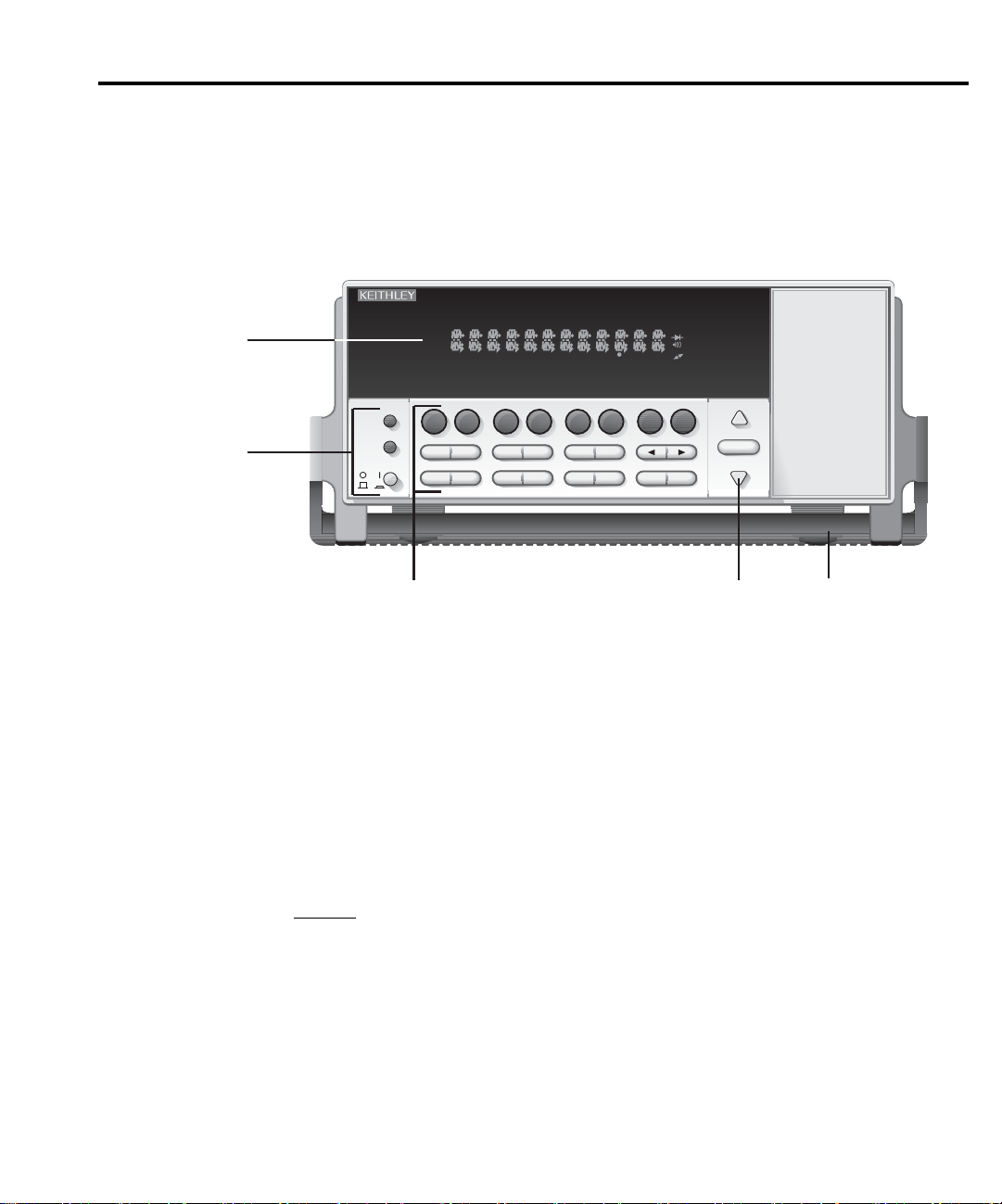
The front panel of Model 6514 is shown in Figure 1-1.
Figure 1-1
Model
6514
front panel
TALK
LSTN
4
SRQ
SHIFT
TIMER
CH1REM
SCAN
STEP CH2 CH3 CH4 CH5 CH6 CH7 CH8 CH9 CH10
HOLD TRIG FAST MED SLOW AUTO ERR
REL FILT
BUFFER
Getting Started 1-5
MATH
REAR
4W
STAT
V-DROP
AUTO-DIS
CONF-LIM
Q
GPIB
XFBK ZCHK
UNITS
CONF-ARM
SHIFT
1
LOCAL
POWER
V
MX+B
AVG
TEST CAL
STORE
MEDN
RCLL
%
I
Ω
VAL
REL LIMIT
SAVE SETUP
DELAY DAMP
23
6514 SYSTEM ELECTROMETER
RS-232
ZCOR
GRD
NPLC
RATEDIGIT
CONF-TRIG
EXIT ENTERHALT TRIG
RANGE
AUTO
RANGE
5
NOTE Most keys provide a dual function or operation. The nomenclature on a key indicates
its unshifted function/operation, which is selected by pressing the key. Nomenclature
(in blue) above a key indicates its shifted function. A shifted function is selected by
pressing the SHIFT key and then the function/operation key.
1 Special keys and power switch
SHIFT Use to select a shifted function or operation.
LOCAL Cancels GPIB remote mode.
POWER Power switch. In position turns 6514 on (I), out position turns it off (O).
2 Function and operation keys
Top Row
Unshifted
V Selects voltage measurement function.
I Selects current measurement function.
Ω Selects resistance measurement function.
Q Selects charge measurement function.
XFBK Enables/disables External Feedback.
ZCHK Enables/disables Zero Check.
ZCOR Enables/disables Zero Correct.
GRD Enables/disables Guard.
Page 28

1-6 Getting Started
Shifted
V-DROP Enables/disables V-drop measurements for Ω function.
AUTO-DIS Sets and enables/disables Auto Discharge for charge measurements.
GPIB Configures and enables/disables GPIB interface.
RS-232 Configures and enables/disables RS-232 interface.
Middle Row
Unshifted
AVG Configures and enables/disables digital filter.
MEDN Configures and enables/disables median filter.
REL Enables/disables Relative (Rel).
LIMIT Performs configured limit tests.
DIGIT Sets display resolution.
RATE Selects measurement rate.
and Controls cursor position for making selections or editing values.
Shifted
MX+B Configures and enables/disables mX+b math function.
% Configures and enables/disables Percent math function.
VAL Sets Rel value and enables Rel.
CONF-LIM Configures limit tests.
UNITS Selects engineering units for scientific notation for display readings.
NPLC Set rate by setting PLC value.
Bottom Row
Unshifted
STORE Sets the number of readings to store and enables the buffer.
RCLL Displays stored readings (including maximum, minimum, peak-to-peak, average,
and standard deviation). The and range keys scroll through the buffer, and the
or key toggles between reading number and reading.
DELAY Sets user delay between trigger and measurement.
DAMP Enables/disables damping for current measurements.
HALT Stops measurement process. Puts 6514 in idle state.
TRIG Trigger measurement(s). Takes 6514 out of idle state.
EXIT Cancels selection, moves back to measurement display.
ENTER Accepts selection, moves to next choice or back to measurement display.
Shifted
TEST Performs key-press test or display test.
CAL Accesses calibration.
SAVE Saves present setup to a memory location.
SETUP Restores setup stored in a memory location, or to GPIB or factory defaults.
CONF-ARM Configures Arm Layer of trigger model.
CONF-TRIG Configures Trigger Layer of trigger model.
3 Range keys
Selects the next higher voltage measurement range.
Selects the next lower voltage measurement range.
AUTO Enables/disables autorange.
Page 29

4 Display annunciators
* (asterisk) Readings being stored in buffer.
↔ (more) Indicates additional selections are available.
AUTO Autorange enabled.
BUFFER Recalling readings stored in buffer.
ERR Questionable reading, or invalid cal step.
FAST Fast (0.1 PLC) reading rate selected.
FILT Filter enabled.
LSTN Instrument addressed to listen over GPIB.
MATH mX+b or Percent (%) calculation enabled.
MED Medium (1 PLC) reading rate selected.
REL Relative enabled for present measurement function.
REM Instrument in GPIB remote mode.
SHIFT Accessing a shifted key.
SLOW Slow reading rate selected; 6 PLC for 60Hz or 5 PLC for 50Hz.
SRQ Service request over GPIB.
STAT Displaying buffer statistics.
TALK Instrument addressed to talk over GPIB bus.
TIMER Timer controlled triggering in use.
TRIG External triggering (GPIB or trigger link) selected.
5 Handle
Pull out and rotate to desired position.
Getting Started 1-7
Page 30
1-8 Getting Started
Rear panel summary
The rear panel of Model 6514 is shown in Figure 1-2.
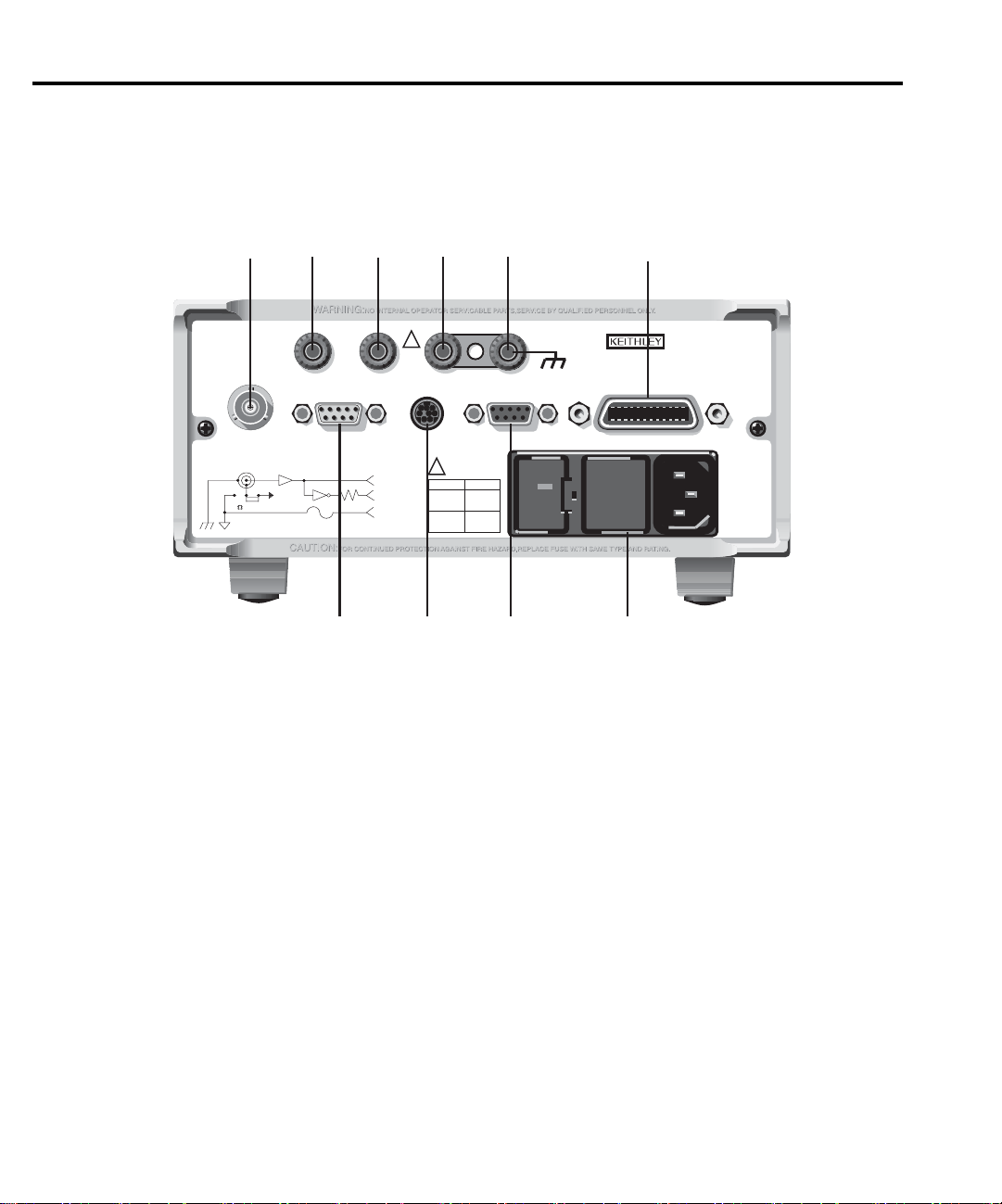
Figure 1-2
Model 6514
rear panel
1
INPUT 250V PK
INPUT PREAMP
OFF
ON
V, GUARD
(PROGRAMMABLE)
PREAMP OUT
250V PK
GUARD
(FOLLOWS
INPUT)
2
(INTERNAL)
2V ANALOG
10K
3
OUTPUT
PREAMP
2V ANALOG
COM
!
COMMON CHASSIS
TRIGGER LINK
OUT
OUTPUT
4
LINE RATING
!
FUSE LINE
630mA
(SB)
315mAT
(SB)
50, 60Hz
60 VA MAX
T
100 VAC
120 VAC
220 VAC
240 VAC
5
RS232DIGITAL I/O
120
6
MADE IN
IEEE-488
(CHANGE IEEE ADDRESS
WITH FRONT PANEL MENU)
U.S.A.
789 10
1 INPUT
This standard 3-lug female triax connector is used to connect the signal to be measured to the input
of Model 6514. Mates to a triax cable terminated with a 3-lug male triax connector.
2 PREAMP OUT
Provides a guard output for Volts measurements. Can be used as an inverting output or with external
feedback for the Amps and Coulombs modes.
32V ANALOG OUTPUT
Provides a scaled DC output voltage. A full range input will result in a 2V analog output.
For the volts function, the output is non-inverting.
4 COMMON
Use as input low, or the common for the 2V Analog Output and Preamp Out.
5 CHASSIS
This terminal is connected to the chassis of Model 6514 and to power line earth ground via the power
line cord. For floating measurements (up to 500V peak), remove the ground link between COMMON
and CHASSIS.
Page 31

Getting Started 1-9
6 IEEE-488
Connector for IEEE-488 (GPIB) operation. Use a shielded cable, such as Models 7007-1 and 7007-2.
7 DIGITAL I/O
Male DB-9 connector for digital output lines and component handler signals.
8 TRIGGER LINK
Eight-pin micro-DIN connector for sending and receiving trigger pulses among connected instruments. Use a trigger link cable or adapter, such as Models 8501-1, 8501-2, 8502 and 8503.
9 RS-232
Female DB-9 connector for RS-232 operation. Use a straight-through (not null modem) DB-9 shielded
cable.
10 Power module
Contains the AC line receptacle, power line fuse, and line voltage setting. The instrument can be configured for line voltages of 100V/120V/220V/240VAC at line frequencies of 50 or 60Hz.
Page 32

1-10 Getting Started
Power-up
Line power connection
Perform the following procedure to connect Model 6514 to line power and turn on the
instrument.
1. Check to be sure the line voltage setting on the power module is correct for the operating
CAUTION Operating the instrument on an incorrect line voltage may cause damage to
2. Before plugging in the power cord, make sure the front panel power switch is in the off
3. Connect the female end of the supplied power cord to the AC receptacle on the rear
WARNING The power cord supplied with Model 6514 contains a separate ground wire
voltage in your area. The line voltage setting is indicated in the window on the power
module (see Figure 1-2). The upside-down 120 setting is for line voltages of 100/
120VAC, and the upside-down 240 setting is for line voltages of 220/240VAC. The procedure to change the line voltage setting is provided in Section 20.
the instrument, possibly voiding the warranty.
(O) position.
panel. Connect the other end of the power cord to a grounded AC outlet.
for use with grounded outlets. When proper connections are made, instrument chassis is connected to power line ground through the ground wire in
the power cord. Failure to use a grounded outlet may result in personal
injury or death due to electric shock.
4. Turn on the instrument by pressing the front panel power switch to the on (1) position.
Line frequency selection
During the power-up sequence, the selected line frequency setting is displayed. The line frequency setting can be changed from the front panel by holding in the TRIG key during the
power-up sequence. This action toggles between 50 and 60Hz. The command to remotely set
line frequency is listed in Table 1-1.
SCPI programming
Table 1-1
SCPI commands - line frequency
Command Description
SYSTem
:LFRequency <freq>
:LFRequency?
SYSTem Subsystem:
Select power line frequency (in Hz); 50 or 60.
Read present line frequency setting.
Page 33

Power-up sequence
The following power-up sequence occurs when the Model 6514 is turned on:
1. The Model 6514 performs self-tests on its EPROM and RAM with all digits and annunciators turned on. If a failure is detected, the instrument momentarily displays an error
message and the ERR annunciator turns on. Error messages are listed in Appendix B.
NOTE If a problem develops while the instrument is under warranty, return it to Keithley
Instruments Inc., for repair.
2. If the instrument passes the self-tests, the firm are revision levels are displayed. For
example:
6514 REV: A01
3. The detected line frequency is then displayed. For example:
FREQ: 60Hz
4. Lastly, information on the selected remote interface is displayed:
a. GPIB — If the GPIB is the selected interface, the instrument will display the
selected language (SCPI or DDC) and primary address. Examples:
SCPI ADDR: 14
DDC ADDR: 14
b. RS-232 — If RS-232 is the selected interface, the instrument will display the baud
rate setting. For example:
RS-232: 9600b
Getting Started 1-11
Page 34

1-12 Getting Started
Display
Readings can be displayed in engineering units or scientif c notation (see “Units” in Section
6 for details). Annunciators indicate various states of operation. See “Front Panel Summary”
(presented earlier in this section) for a complete listing of display annunciators.
NOTE The Display and Keys Test allows you to test display digit segments and annunciators,
and check the functionality of front panel keys. These tests are accessed by pressing
SHIFT and then TEST. Refer to Section 20 for details.
Status and error messages
Status and error messages are displayed momentarily. During operation and programming,
you will encounter a number of front panel messages. Typical messages are either of status or
error variety, as listed in Appendix B.
Default settings
Model 6514 can be restored to one of f ve default setup conf gurations; factory (FACT), GPIB
and three user-saved (USR0, USR1 and USR2). As shipped from the factory, Model 6514 powers up to the factory default settings. Factory default settings provide a general purpose setup for
front panel operation, while the GPIB default settings do the same for remote operation. Factory
and GPIB default settings are listed in Table 1-2.
For front panel operation, the instrument will power up to whichever default setup was last
saved or restored. For example, if you save the present instrument setup as USR0, the instrument
will subsequently power up to the USR0 setup.
NOTE At the factory, the factory default setup is saved as the USR0, USR1 and USR2 setups.
Saving a user setup — Perform the following steps to save a user setup:
1. Configure Model 6514 for the desired measurement application.
2. Press SHIFT and then SAVE to access the save setup menu.
3. Use the
2 = USR2).
4. Press ENTER.
Restoring a setup — Perform the following steps to restore a setup:
1. Press SHIFT and then SETUP to display the restore menu:
2. Use the
3. Press ENTER.
▲ or ▼ key to display the desired memory location (0 = USR0, 1 = USR1,
▲ or ▼ key to display the desired setup (FACT, GPIB, USR0, USR1 or USR2).
Page 35

Getting Started 1-13
Remote operation
Saving and restoring user setups — The *SAV and *RCL commands are used to save and
recall user setups. These commands are documented in Section 14.
Restoring factory or GPIB default setups — The SYSTem:PRESet command returns
Model 6514 to the factory defaults and the *RST command returns it to the GPIB defaults. The
*RST command is documented in Section 14 and SYSTem:PRESet is covered in Section 16
(SYSTem Subsystem).
Selecting power-on setup — The SYSTem:POSetup command is used to select which setup
to return to on power-up. The SYSTem:POSetup command is documented in Section 16
(SYSTem Subsystem).
Table 1-2
Default settings
Setting Factory GPIB
Arm Layer (CONF-ARM):
Arm-In Source Event IMM IMM
Arm Count INF 1
Input Trigger Link Line 1 1
Source Bypass NEVER NEVER
Output Trigger Link Line 2 2
Output Trigger Off Off
Auto Discharge Off Off
Level 2e-6 2e-6
Buffer (STORE): Disabled Disabled
Count No effect No effect
Digital Filter (AVG): Off Off
Count 10 10
Type Moving Moving
Display Resolution (DIGIT) 5½-digits 5½-digits
Function Volts Volts
Guard Off Off
GPIB: No effect (On at factory) No effect (On at factory)
Address No effect (14 at factory) No effect (14 at factory)
Language No effect (SCPI at factory) No effect (SCPI at factory)
Page 36

1-14 Getting Started
Table 1-2 (cont.)
Default settings
Setting Factory GPIB
Limit Tests:
Limit 1 and Limit 2: Disabled Disabled
Digital Output Pass Pattern 15 15
Auto-Clear Off Off
Line 4 Mode End of Test End of Test
Median Filter: Off Off
Rank 1 1
MX+B: Disabled Disabled
“M” Value 1.0 1.0
“B” Value 0.0 0.0
Units MXB MXB
Percent: Disabled Disabled
Reference 1.0 1.0
Range 20V Auto
Rate: Slow Slow
NPLC 6.0 (60Hz) or 5.0 (50Hz) 6.0 (60Hz) or 5.0 (50Hz)
Rel: Off Off
Rel Value (VAL) 0.0 0.0
RS-232: No effect (Off at factory) No effect (Off at factory)
All Settings No effect No effect
Trigger Layer (CONF-TRIG):
Trig-In Source Event IMM IMM
Trigger Count 1 1
Trigger Delay 0 0
Input Trigger Link Line 1 1
Source Bypass NEVER NEVER
Output Trigger Link Line 2 2
Units No effect No effect
V-Drop Disabled Disabled
Zero Check Enabled Enabled
Zero Correct Disabled Disabled
HI and LO Values 1, -1 1, -1
Digital Fail Output Patterns 15 15
Delay 0.00010 sec 0.00010 sec
Output Clear Pattern 15 15
Page 37

SCPI programming
SCPI programming information is integrated with front panel operation throughout this manual. SCPI commands are listed in tables, and additional information that pertains exclusively to
remote operation is provided after each table. The SCPI tables may reference you to other sections of this manual.
NOTE Except for Section 17, most SCPI tables in this manual are abridged. That is, they
exclude most optional command words and query commands. Optional command
words and query commands are summarized as follows.
Optional command words — In order to be in conformance with the IEEE-488.2 standard,
Model 6514 accepts optional command words. Any command word that is enclosed in brackets
([]) is optional and does not have to be included in the program message.
Query commands — Most command words have a query form. A query command is iden-
tified by the question mark (?) that follows the command word. A query command requests (queries) the programmed status of that command. When a query command is sent and Model 6514
is addressed to talk, the response message is sent to the computer.
NOTE For complete details, see “Programming Syntax” in Section 12.
Getting Started 1-15
Page 38

2
Measurement Concepts
• Measurement overview — Explains the basic measurement capabilities of Model 6514.
• Performance considerations — Covers a couple of considerations that affect overall
performance; warm-up and autozero.
• Connection fundamentals — Covers fundamental information about connecting test
circuits to the electrometer.
• Zero check and zero correct — Provides operation information on these two important
aspects of the basic measurement process.
• Measurement considerations — Summarizes the various factors that affect low level
measurements.
Page 39

2-2 Measurement Concepts
Measurement overview
The basic measurement capabilities of Model 6514 are summarized in Table 2-1. Accuracy
for each measurement function and range is listed in specif cations (Appendix A).
Table 2-1
Basic measurement capabilities
Function Reading Range Available Ranges
Volts ±10uV to ±210V 2V, 20V and 200V
Amps ±100aA to ±21mA 20pA, 200pA, 2nA, 20nA, 200nA, 2uA, 20uA,
Ohms 10mΩ to 210GΩ 2kΩ, 20kΩ, 200kΩ, 2MΩ, 20MΩ, 200MΩ, 2GΩ,
Coulombs 10fC to 21µC 20nC, 200nC, 2µC, and 20µC
Performance considerations
200uA, 2mA and 20mA
20GΩ and 200GΩ
Warm-up period
Model 6514 can be used within one minute after it is turned on. However, the instrument
should be turned on and allowed to warm up for at least one hour before use to achieve rated
accuracy. If the instrument has been exposed to extreme temperatures, allow extra time for the
internal temperature to stabilize.
Autozero
To help maintain stability and accuracy over time and changes in temperature, the Model
6514 periodically measures internal voltages corresponding to offsets (zero) and amplif er gains.
These measurements are used in the algorithm to calculate the reading of the input signal. This
process is known as autozeroing.
When autozero is disabled, the offset and gain measurements are not performed. This
increases measurement speed. However, the zero and gain reference points will eventually drift
resulting in inaccurate readings of the input signal. It is recommended that autozero only be disabled for short periods of time.
Autozero cannot be disabled from the front panel, however, it can be enabled from the front
panel by restoring factory or GPIB default conditions.
Page 40

SCPI programming
Table 2-2
SCPI commands — autozero
Command Description Default
SYSTem SYSTem Subsystem:
:AZERo
[:STATe] <b> Enable or disable autozero. ON
Programming example
The following command sequence will perform one zero corrected amps measurement:
SYST:AZER OFF ‘ Disable autozero.
SYST:AZER ON ‘ Enable autozero.
Connection fundamentals
Measurement Concepts 2-3
The following provides important fundamental information on input connections to Model
6514. Typical connection drawings are included with the various measurement procedures provided in subsequent sections of this manual.
Input connector
The rear panel INPUT connector is a 3-lug female triax connector that will mate to a cable
terminated with a male triax connector.
Page 41

2-4 Measurement Concepts
Input configurations
As shown in Figure 2-1, the input connector can be conf gured in two ways. With guard off
(Figure 2-1A), input low is connected to the inner shell of the connector. This configuration is
used for Amps, Coulombs, unguarded Volts and unguarded Ohms measurements.
With guard on (Figure 2-1B), the driven guard is connected to the inner shell of the triax connector. Input low is accessed via the COMMON terminal through an internal 0.1Ω fuse. This
configuration is used for guarded Volts and guarded Ohms measurements only. The GRD key
toggles guard on and off.
NOTE The state of guard (on or off) has no affect on the Amps and Coulombs functions. The
unguarded configu ation is always selected for the Amps and Coulombs functions.
Figure 2-1
Input connector
configurations
INPUT
250V PEAK
Volts, Amps, Ohms & Coulombs
A. Unguarded (GRD off)
Input High
Guard
Chassis
INPUT
250V PEAK
Volts and Ohms only
Ground
B. Guarded (GRD on)
Input High
Input Low
Chassis Ground
COMMON
<1Ω
Fuse
Input Low
Page 42

Measurement Concepts 2-5
Maximum input levels
The maximum input levels to Model 6514 are summarized in Figure 2-2.
WARNING The maximum common-mode input voltage, which is the voltage between
the input (HI or LO) and chassis ground, is 500V peak. Exceeding this value
may create a shock hazard.
CAUTION Connecting PREAMP OUT, COMMON, or 2V ANALOG OUTPUT to
earth while floating the input may damage the instrument.
Figure 2-2
Maximum input levels
Low noise input cables
ing low noise cables are recommended for use with Model 6514:
Input High
Max Input Signal *
Input Low
Chassis Ground
* Max Input Signal - 250V Peak, DC to 60Hz sine wave
(10 seconds maximum in mA ranges).
500V Peak
500V Peak
When making precision measurements, you should always use low noise cables. The follow-
• Model 237-ALG-2 — This 2-meter low noise triax cable mates directly to the input connector of Model 6514. The other end is terminated with three alligator clips. The clip
with the red boot is input high, black boot is input low or guard, and the green boot is
chassis ground.
• Model 7078-TRX-3 — This 3-foot low noise triax cable is terminated with a 3-slot triax
connector on either end.
• Models 7078-TRX-10 and 7078-TRX-20 — Same as Model 7078-TRX-3 except that
they are 10 feet and 20 feet in length.
NOTE As a general rule, always use the shortest possible cable for volts, amps and ohms
measurements.
Page 43

2-6 Measurement Concepts
Basic connections to DUT
Unguarded connections
Basic unguarded connections are shown in Figure 2-3, the DUT is the voltage, current, resistance or charge to be measured. Circuit high is connected to the center conductor of the input
connector and circuit low is connected to the inner shell of the connector. For unguarded volts
and ohms measurements, the driven guard (GRD) must be off.
Figure 2-3
Basic connections for
unguarded measurements
INPUT
250V PK
NOTE:
HI
DUT
LO
For Volts and Ohms,
GRD must be off.
Page 44

Measurement Concepts 2-7
Noise and safety shields — Figure 2-4 shows typical shielding for unguarded measure-
ments. A noise shield is used to prevent unwanted signals from being induced on the electrometer input. Measurements that may benef t from effective shielding include unguarded volts and
ohms, amps below 1uA, and low level coulombs.
Typically, the noise shield is connected to electrometer input LO. However, better noise performance may be achieved by connecting the noise shield to both input LO and chassis ground.
Electrometer LO can be connected to chassis ground by installing the ground link between the
COMMON and CHASSIS binding posts.
A safety shield is required whenever a hazardous voltage (>30V) is present on the noise
shield or when the test circuit (DUT) is f oated above earth ground at a hazardous voltage level
(see “Floating Measurements”). Connections for the safety shield is shown in Figure 2-4B. The
metal safety shield must completely surround the noise shield or f oating test circuit, and it must
be connected to safety earth ground using #18 AWG or larger wire.
Figure 2-4
Shielding for
unguarded
measurements
INPUT
250V PK
A. Noise Shield
Chassis
Ground
INPUT
250V PK
B. Safety Shield
HI
LO
HI
LO
DUT
DUT
Metal Noise Shield
Metal Noise Shield
Metal Safety Shield
Safety
Earth
Ground
Page 45

2-8 Measurement Concepts
Guarded connections
The basic guarded connections for volts and ohms are shown in Figure 2-5. For these measurements, circuit high is connected to the center conductor of the input connector while circuit
low is connected to the COMMON banana jack terminal. With guard (GRD) on, the driven
guard is available at the inner shell of the triax connector which is connected to the metal guard
plate.
WARNING The guard voltage is at the same potential as the input. Therefore, hazard-
WARNING With an open input, up to 250V peak may be present on the guard terminals
The driven guard is used to eliminate leakage current and capacitance in high impedance circuits which could corrupt the volts or ohms measurement. The concept of guarding techniques
are covered in Section 3.
ous voltage on the input will also be present on the guard plate. To prevent
electric shock, always use a metal safety shield (as shown in Figure 2-5) for
guarded voltage measurements above 30Vrms (42V peak). The metal safety
shield must be connected to safety earth ground using #18 AWG or larger
wire.
while in Volts or Ohms. To prevent this, enable zero check whenever the
input is open.
Figure 2-5
Basic connections
for guarded
measurements
Measure Volts
INPUT
250V PK
COMMON
Measure Ohms
INPUT
250V PK
COMMON
HI
Chassis
Ground
GRD
LO
HI
Chassis
Ground
GRD
LO
NOTE: GRD must be on.
Metal Guard Plate
V
Safety
Earth
Ground
Metal Guard Plate
Ω
Safety
Earth
Ground
Metal Safety Shield
Metal Safety Shield
Page 46

Test fixture
Whenever possible, use a shielded low leakage test f xture to make precision measurements.
A general purpose test f xture is shown in Figure 2-6. This test fixture will accommodate a variety of connection requirements.
Measurement Concepts 2-9
Figure 2-6
General
purpose test
fixture
Metal Chassis
To External
Source
To 6514
Input
To 6514
COMMON
A
B
A
A
Banana Jacks
B
3-Lug Female Triax Connector
Metal Guard Plate
DUT
Insulated
Terminal
Post (6)
Test fixture chassis
• The chassis of the test f xture should be metal so that it can function as a shield for the
DUT or test circuit. The metal chassis should be connected to chassis ground of Model
6514 via the triax cable.
• The test box must have a lid that closes to prevent contact with live circuitry.
• The test fixture must have a screw terminal that is used exclusively for connection to
safety earth ground.
Safety
Earth
Ground
WARNING To provide protection from shock hazards, the test fixture chassis must be
properly connected to safety earth ground. A grounding wire (#18 AWG or
larger) must be attached securely to the test fixture at a screw terminal
designed for safety grounding. The other end of the ground wire must be
attached to a known safety earth ground.
Guard plate
A metal guard plate will provide guarding or noise shielding for the DUT or test circuit. It
will also serve as a mounting panel for DUT or test circuits. The guard plate must be insulated
with 1000V spacing from the chassis of the test f xture.
Page 47

2-10 Measurement Concepts
Connectors, terminals and internal wiring
Basic connector requirements include a 3-lug female triax connector, and three banana jacks.
One banana jack is used to make the COMMON connection to the electrometer for guarded
measurements. The other two banana jacks will accommodate connection to an external power
supply. The banana jacks must be insulated from the chassis of the test f xture. The outer shell
of the triax connector must be referenced to chassis ground. Therefore, DO NOT insulate the
outer shell of the triax connector from the metal chassis of the test f xture.
DUT and test circuits are to be mounted on the guard plate using insulated terminals. To minimize leakage, select terminals that use virgin Teflon insulators.
Inside the test f xture, use an insulated wire to connect the inner shell of the triax connector
to the guard plate. For unguarded measurements, the guard plate will serve as a noise shield. For
the volts and ohms functions, turning GRD on will connect guard to the guard plate.
Handling and cleaning test fixtures
Dust, body oil, solder f ux, and other contaminants on connector and terminal insulators can
significantly decrease the leakage resistance resulting in xcessive leakage currents. Contaminants on DUT and test circuit components can create a leakage path. The leakage currents may
be large enough to corrupt low-level measurements.
Handling tips:
• Do not touch the bodies of DUT or test circuit components. If you cannot handle them
by their leads, use clean cotton gloves to install them in the test f xture.
• Do not touch any connector or terminal insulator.
• If installing a test circuit that is on a PC board, handle the board by the edges. Do not
touch any board traces or components.
Cleaning tips:
• Use dry nitrogen gas to clean dust off connector and terminal insulators, DUT, and other
test circuit components.
• If you have just built the test f xture, remove any solder flux using methanol along with
clean foam-tipped swabs or a clean soft brush. Clean the areas as explained in the next
tip.
•To clean contaminated areas, use methanol and clean foam-tipped swabs. After cleaning
a large area, you may want to flush the area with methanol. Blow dry with dry nitrogen
gas.
• After cleaning, the test f xture (and any other cleaned devices or test circuits) should be
allowed to dry in a 50
o
C low-humidity environment for several hours.
Page 48

Input protection
a high voltage (>250V) and resultant current surge could damage the input circuitry. A typical
test circuit to measure the leakage current of a capacitor is shown in Figure 2-7. When Switch S
is closed, an initial charging current will f ow and the high voltage will be seen across the input
of Model 6514.
Figure 2-7
Capacitor test circuit
without protection
extra protection. The resistor must be large enough to limit the current through the diodes to
10mA or less, and be large enough to withstand the supply voltage. The protection circuit should
be enclosed in a light-tight conductive shield.
Measurement Concepts 2-11
Model 6514 incorporates protection circuitry against nominal overload conditions. However,
S
V
Capacitor
Under Test
A
6514
Ammeter
Adding a resistor and two diodes (1N3595) as shown in Figure 2-8 will provide considerable
Figure 2-8
Capacitor test
circuit with
protection
Floating measurements
Protection Circuit
S
Capacitor
Under Test
V
R
D1 D2
HI
A
LO
6514
Ammeter
With the ground link between the COMMON and CHASSIS banana jack terminals removed,
Model 6514 can perform f oating measurements up to 500V above chassis ground. These measurements can result in safety concerns.
Page 49
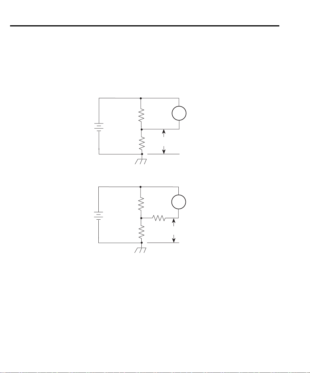
2-12 Measurement Concepts
Figure 2-9 shows two examples where Model 6514 f oats at a hazardous voltage level. In Figure 2-9A, a shock hazard (100V) exists between meter input LO and chassis ground. If meter
input LO is connected to a noise shield, then the shock hazard will also be present on that shield.
In Figure 2-9B, a shock hazard (200V) exists between the meter input (HI and LO) and chassis ground. If meter LO is connected to a shield, then the shock hazard will also be present on
that shield.
Figure 2-9
Floating measurements
+
R
200V
(R
= R2)
1
-
R
A. Voltage measurement
+
R
200V
-
R
B. Current measurement
HI
6514
V
LO
A
HI
Voltmeter
LO
6514
Ammeter
1
2
1
2
100V
R
3
200V
WARNING The maximum voltage (common-mode) between electrometer LO and chas-
sis ground is 500V. Exceeding this value may create a shock hazard.
WARNING When floating input LO above 30V from earth (chassis) ground, hazardous
voltage will be present at the analog outputs (PREAMP OUT and 2V
ANALOG OUTPUT). Hazardous voltage may also be present when the
input voltage exceeds 30V in the Volts function.
CAUTION Connecting PREAMP OUT, COMMON or 2V ANALOG OUTPUT to
earth (chassis) ground while floating the input may damage the instrument.
Page 50

Zero check and zero correct
Table 2-3 lists the display messages associated with zero check and zero correct. The
two-character message is displayed along with the reading.
Table 2-3
Display messages for zero check and zero correct
Display
Message
ZC On Off
ZZ On On
CZ Off On
Zero check
When zero check is enabled (on), the input amplif er is reconf gured to shunt the input signal
to low as shown in Figure 2-10. With zero check enabled, it will remain enabled when a different
function is selected. With zero check disabled, it will remain disabled when the volts, amps or
coulombs function is selected.
Zero Check Zero Correct
Measurement Concepts 2-13
NOTE Zero check will always enable whenever the ohms function is selected.
Zero check is enabled by pressing the ZCHK key. Pressing ZCHK a second time disables zero
check.
NOTE To ensure proper operation, always enable zero check before changing functions.
For coulombs, enabling zero check dissipates the charge. That is, the charge reading is reset
to zero. When zero check is disabled, a sudden change in the charge reading (zero check hop)
occurs. This effect can be cancelled by enabling Relative (REL) immediately after zero check is
disabled. Relative is explained in Section 7.
Page 51
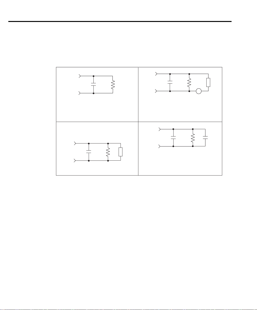
2-14 Measurement Concepts
For volts, amps and ohms, leave zero check enabled when connecting or disconnecting input
signals. For coulombs, disable zero check before connecting the input signal. If zero check is
left enabled when you connect the input signal, the charge will dissipate through the 10MΩ
resistor (see Figure 2-10).
Figure 2-10
Equivalent input
impedance with
zero check enabled
Input
C
C
IN
10MΩ
Input
IN
10MΩ
Z
F
Zero correct
Model 6514 has a zero correct feature to algebraically subtract the voltage offset term from
the measurement. Perform the following steps to zero correct the volts or amps function:
NOTE The ZCOR key toggles zero correct on and off. If zero correct is enabled (“ZZ” or
CIN = 10pF
Z
= 1kΩ (mA)
F
1MΩ || 1000pF (µA)
1GΩ || 10pF (nA)
1TΩ || 1pF (pA)
C
IN
Input
CIN = 10pF
10MΩ
Amps
Volts and Ohms
Z
F
CIN = 10pF
Input
CIN = 10pF
“CZ” message displayed), press ZCOR to disable it.
=
1kΩ (kΩ)
Z
F
1MΩ || 1000pF (MΩ)
1GΩ || 10pF (GΩ)
C
IN
10MΩ
Coulombs
C
= 1000pF (20nC, 200nC)
F
0.1µF (2µC, 20µC)
I
IN
Ohms
C
F
1. Select the volts (V) or amps (I) function.
2. Enable zero check (“ZC” message displayed).
3. Select the range that will be used for the measurement, or select the lowest range.
4. Press ZCOR to enable zero correct (“ZZ” message displayed).
5. Press ZCHK to disable zero check.
6. Readings can now be taken from the display. The “CZ” message indicates that the displayed reading is zero corrected.
Page 52

Measurement Concepts 2-15
NOTES Zero check will enable whenever the ohms function is selected.
Model 6514 will remain zeroed even if it is upranged. If downranged, re-zero the
instrument.
Model 6514 does not have to be re-zeroed as long as the ambient temperature remains
stable.
Zero correction cancels the voltage offset term of the amplif er. With both zero check
and zero correct enabled, the instrument may not display a perfectly zeroed reading.
If Model 6514 is operating at, or near T
T
is the internal temperature of Model 6514 when it was last calibrated.
CAL
, zero correction will have very little affect.
CAL
SCPI programming — zero check and zero correct
Table 2-4
SCPI commands — zero check and zero correct
Commands Description Default Ref
SYSTem SYSTem Subsystem:
:ZCHeck <b> Enable or disable zero check. ON
:ZCORrect Zero correct:
[:STATe] <b> Enable or disable zero correct. OFF A
:ACQuire Acquire a new zero correct value. B
INITiate Trigger a reading. B
A) SYST em:ZCORrect[:ST A Te] <b>
This method to perform zero correction is consistent with the way it is performed from the
front panel. That is, zero correction is performed while zero check is enabled:
SYST:ZCH ON ‘ Enable zero check.
SYST:ZCOR ON ‘ Perform zero correction.
A second method to perform zero correction is to f rst acquire the zero correct value (see
Ref. B).
Page 53

2-16 Measurement Concepts
B) SYST em:ZCORrect:ACQuire
The zero correct value can only be acquired while zero check is enabled. The internal offset
will become the correction value. Zero correction can then be performed with zero check disabled. This acquire method makes it convenient if you need to re-zero the selected function
often.
The following command sequence uses the acquire method to zero correct the 2V range:
SYST:ZCH ON ‘ Enable zero check.
FUNC ‘VOLT’ ‘ Select Volts function.
VOLT:RANG 2 ‘ Select 2V range.
INIT ‘ Trigger one reading.
SYST:ZCOR:ACQ ‘ Acquire zero correct value.
SYST:ZCH OFF ‘ Disable zero check.
SYST:ZCOR ON ‘ Perform zero correction.
The INITiate command in the above sequence is used to trigger a reading. This reading is the
offset that is acquired as the zero correct value. See Section 9 for more information on INITiate.
NOTE Sending the :ACQuire command while zero check is disabled will result in an error.
The command will not be executed.
Page 54

Measurement Concepts 2-17
Input bias current and offset voltage calibration
The input bias current and offset voltage calibration procedures that follow should be performed periodically to actively cancel input bias current and offset voltage, optimizing measurement accuracy, particularly at low levels.
Front panel
Front panel input bias current calibration
1. Access the front panel calibration menu by pressing SHIFT then CAL.
NOTE See Section 19 for details on other calibration menu selections.
2. From the calibration menu, use the down RANGE key to display the following:
CAL: IOFFSET
3. Press ENTER. The instrument will prompt for the triax shielding cap as follows:
INPUT CAP
4. Connect a triax shielding cap to the rear panel INPUT jack. (Use a Keithley CAP-31 or
equivalent.)
5. Press ENTER to complete input bias current calibration.
6. If you wish to perform front panel offset voltage calibration, proceed to Step 2 of the procedure below. Otherwise, press EXIT to return to normal display.
Front panel offset voltage calibration
1. Access the front panel calibration menu by pressing SHIFT then CAL.
2. From the calibration menu, use the up or down RANGE key to display the following:
CAL: VOFFSET
3. Press ENTER. The instrument will prompt for a short:
INPUT SHORT
4. Connect a triax short to the rear panel INPUT jack. (Use the supplied Model 237-ALG2 triax cable or equivalent with red and black alligator clips connected together.)
5. Press ENTER to complete offset voltage calibration.
6. Press EXIT to return to normal display.
Page 55

2-18 Measurement Concepts
SCPI programming
Table 2-5 lists SCPI commands used for input bias current and offset voltage calibration.
Table 2-5
SCPI commands — input bias current and offset voltage calibration
Commands Description
:CALibration:UNPRotected:IOFFset
:CALibration:UNPRotected:VOFFset
Input bias current calibration.
Offset voltage calibration.
SCPI command input bias current calibration
1. Connect a triax shielding cap to the rear panel INPUT jack. (Use a Keithley CAP-31 or
equivalent.)
2. Send the following command to perform input bias current calibration:
:CAL:UNPR:IOFF
3. Allow the Model 6514 to complete the calibration process.
SCPI command offset voltage calibration
1. Connect a triax short to the rear panel INPUT jack. (Use the supplied Model 237-ALG-2
triax cable or equivalent with red and black alligator clips connected together.)
2. Send the following command to perform offset voltage calibration:
:CAL:UNPR:VOFF
3. Allow the Model 6514 to complete the calibration process.
Page 56

Measurement Concepts 2-19
Measurement considerations
There are a variety of factors to consider when making low level measurements. These considerations are listed and summarized in Table 2-6. For comprehensive information on all measurement considerations, refer to the Low Level Measurements handbook, which is available
from Keithley Instruments.
Table 2-6
Summary of measurement considerations
Considerations Description
For V and Ω measurements: See Section 3 for details
Loading effects Circuit loading caused by a high impedance voltage source.
Cable leakage resistance For unguarded measurements, leakage resistance in the triax cable
(between HI and LO) shunts the voltage to be measured.
Input capacitance (settling
time)
Guarding input cable Eliminates the effects of leakage resistance for high impedance
At very high resistance levels, effects of cable capacitance can slow
down measurement response time.
measurements and input capacitance when using a long input cable.
For I measurements: See Section 4 for details
Input bias current Offset current of Model 6514 could affect low current
measurements.
Voltage burden Offset voltage of Model 6514 could cause errors if it is high in
relation to the voltage of the measured circuit.
Noise Noise generated by source resistance and source capacitance.
For Q measurements: See Section 5 for details
Input bias current Offset current of Model 6514 is integrated along with the input
signal, affecting the f nal reading.
External voltage source Input current to Model 6514 should be limited to <1mA.
Zero check hop Sudden change in the charge reading when zero check is turned off.
Auto-discharge hop Sudden change in the charge reading when auto-discharge resets the
charge reading to zero.
Page 57

2-20 Measurement Concepts
Table 2-6 (cont.)
Summary of measurement considerations
Considerations Description
For all measurements: See Appendix C for details
Ground loops Multiple ground points can create error signals.
Triboelectric effects Charge currents generated in a cable by friction between a conductor
and the surrounding insulator (i.e. bending a triax cable).
Piezoelectric and stored
charge effects
Currents generated by mechanical stress on certain insulating
materials.
Electrochemical effects Currents generated by the formation of chemical batteries on a
circuit board caused by ionic contamination.
Humidity Reduces insulation resistance on PC boards and test connection
insulators.
Light Light sensitive components must be tested in a light-free
environment.
Electrostatic interference Charge induced by bringing a charged object near your test circuit.
Magnetic field The presence of magnetic f elds can generate EMF (voltage).
Electromagnetic interference
(EMI)
EMI from external sources (i.e. radio and TV transmitters) can
affect sensitive measurements.
Page 58

3
Volts and Ohms
Measurements
• Measurement overview — Summarizes the volts and ohms measurement capabilities of
Model 6514.
• Guarding — Explains guarding and the benef ts derived from it for high-impedance
volts and ohms measurements.
• Volts and ohms measurement procedure — Provides the procedure to measure volts
and ohms.
• SCPI programming — Covers the basic SCPI command used for the volts and ohms
functions.
• Volts and ohms measurement considerations — Covers measurement considerations
that apply to volts and ohms measurements.
• Application — Shows how to measure dielectric absorption of a capacitor.
Page 59

3-2 Volts and Ohms Measurements
Measurement overview
Volts measurements — Model 6514 can make volts measurements from 10µV to 210V
using three measurement ranges; 2V, 20V, and 200V.
Ohms measurements — Model 6514 makes ohms measurements by sourcing a test current
and measuring the voltage drop across the DUT. The resistance reading is then calculated
(R = V/1) and displayed. The electrometer can make ohms measurements from 10mΩ to 210GΩ
using nine measurement ranges; 2kΩ, 20kΩ, 200kΩ, 2MΩ, 20MΩ, 200MΩ, 2GΩ, 20GΩ,and
200GΩ.
NOTE Accuracy specifications for all measurement functions are provided in Appendix A.
Guarding
The purpose of guarding is to eliminate the effects of leakage resistance and capacitance, that
can exist between input HI and input LO. This leakage resistance and capacitance could
adversely affect high-impedance measurements.
Test circuit leakage
In a test circuit, leakage current can occur through the insulators of the terminals for the DUT
(device under test). In Figure 3-1, the test circuit consists of a current source in series with the
DUT. The objective is to make an accurate voltage measurement of the DUT.
In Figure 3-1A, a resistance leakage path through the insulators (RL1 and RL2) shunts current around the DUT. If this leakage current is high in comparison to the DUT current, signif cant measurement error will occur. To keep error <0.1%, the leakage resistance must be 1000
times greater than the resistance of the DUT. For example, if the nominal resistance of the DUT
is 100MΩ, leakage resistance must be >100GΩ.
Figure 3-1B shows how to use guarding to eliminate the effects of leakage resistance. With
GRD enabled, the driven guard, which is at the same potential as input HI, is connected to the
metal mounting plate (now known as the guard plate). With both ends of RL1 at the same potential, current will not f ow through the insulator. With no current leakage path, all current f ows
through the DUT allowing an accurate voltage measurement.
The above explanation also pertains to ohms measurements. The only difference is that the
test current is provided by Model 6514.
Page 60

Volts and Ohms Measurements 3-3
Figure 3-1
High-impedance
voltage measurements
6514
HI
LO
COMMON
GRD Disabled
A. Unguarded
6514
HI
GRD
COMMON
GRD Enabled
LO
0V
Insulator
(one of two)
RL1
Insulator
(one of two)
RL1
DUT
RL2
Leakage Path
Metal Mounting Plate
DUT
Metal Mounting Plate
B. Guarded
Input cable leakage and capacitance
In a similar manner to leakage in the test circuit, leakage in the input cable could also corrupt
high-impedance measurements. In the unguarded mode, leakage in a triax cable occurs between
the center conductor (HI) and the inner shield (LO).
Inherently, an input cable has capacitance that is formed by the center conductor (HI), inner
shield (LO) and the insulator between them. For high-impedance measurements, the RC time
constant can signif cantly slow down measurement response.
To minimize the effects of cable leakage, and input capacitance, keep the input cable as short
as possible and use guard. With guard enabled, the same potential is applied to both the center
conductor and inner shield of the cable. This eliminates leakage current and capacitor charging/
discharging.
NOTE Detailed information on "Cable Leakage Resistance”, “Input Capacitance (Settling
Time)” and “Guarding Input Cables” is provided in “Volts and Ohms Measurement
Considerations” (located in this section).
Page 61

3-4 Volts and Ohms Measurements
Volts and ohms measurement procedure
CAUTION The maximum input voltage to Model 6514 is 250V peak. Exceeding this
value may cause damage to the instrument that is not covered by the
warranty.
WARNING The maximum common-mode input voltage, which is the voltage between
the input (HI or LO) and chassis ground, is 500V peak. Exceeding this value
may create a shock hazard.
Step 1 Enable zero check and select the volts (V) or ohms (Ω) function
Zero check should always be enabled before making function or connection changes. The
ZCHK key toggles zero check on and off. When on, the “ZC” or “ZZ” message is displayed. See
Section 2 for details on zero check.
The volts function is selected by pressing the V key, and the ohms function is selected by
pressing the Ω key.
NOTE Zero check will enable whenever the ohms function is selected.
Step 2 Enable or disable guard
The GRD key toggles the driven guard on and off. If performing unguarded measurements,
press GRD until the “GUARD OFF” message is displayed. If performing guarded measurements, press GRD until the “GUARD ON” message is displayed.
WARNING Hazardous voltage may be present on the inner shield of the triax cable
when GRD is on. A metal safety shield connected to safety earth ground (as
shown in Figure 3-5) must be used for voltage measurements at or above
30V.
Step 3 Perform zero correction (volts only)
To achieve optimum accuracy for low voltage measurements, it is recommended that you zero
correct the electrometer. To do so, select the 2V range (which is the lowest range) and press the
ZCOR key until the “ZZ” message is displayed. See Section 2 for details on zero correction.
Step 4 Select a manual measurement range or enable auto range
Use the RANGE and keys to select a manual measurement range, or press AUTO to
enable auto range. With auto range enabled, the instrument will automatically go to the most
sensitive range to make the measurement. See Section 6 for details on range.
Page 62

Volts and Ohms Measurements 3-5
Step 5 Connect the DUT to the electrometer
NOTE Fundamental information on making connections to the electrometer input is pro-
vided in Section 2 (“Connection Fundamentals”).
WARNING A metal safety shield is required whenever a hazardous voltage (>30V) is
present on a noise shield or guard shield. As shown in Figures 3-2 and 3-3,
the safety shield must be connected to safety earth ground using #18 AWG
wire or larger.
Unguarded connections — Connections for unguarded volts and ohms measurements are
shown in Figure 3-2, where the DUT is the voltage or resistance to be measured. If a hazardous
voltage (>30V) is present on the noise shield, or the test circuit is f oating above earth ground at
a hazardous voltage level, a safety shield must be used as shown.
Figure 3-2
Connections for
unguarded volts and
ohms
237-ALG-2
Cable
Red (HI)
(Chassis)
Black (LO)
PREAMP OUT
INPUT 250V PK
INPUT PREAMP
OFF
ON
GUARD
(FOLLOWS
V, GUARD
INPUT)
(PROGRAMMABLE)
GRD Disabled
Green
250V PK
(INTERNAL)
2V ANALOG
10K
OUTPUT
PREAMP
2V ANALOG
COM
DUT
!
COMMON CHASSIS
TRIGGER LINK
OUT
OUTPUT
6514 Rear Panel
LINE RATING
50, 60Hz
!
60 VA MAX
FUSE LINE
630mA
T
100 VAC
(SB)
120 VAC
220 VAC
315mAT
240 VAC
(SB)
Metal Noise Shield
Metal Safety Shield
Safety
Earth
Ground
RS232DIGITAL I/O
120
MADE IN
IEEE-488
(CHANGE IEEE ADDRESS
WITH FRONT PANEL MENU)
U.S.A.
Page 63

3-6 Volts and Ohms Measurements
Guarded connections — Connections for guarded volts and ohms measurements are shown
in Figure 3-3. The driven guard (GRD) must be enabled for these measurements.
WARNING With an open input, up to 250V peak may be present on the guard terminals
while in Volts or Ohms. To prevent this, make sure zero check is enabled
whenever the input is open.
Figure 3-3
Connections for
guarded volts and
ohms
237-ALG-2
Metal Guard Plate
Cable
INPUT 250V PK
INPUT PREAMP
OFF
V, GUARD
(PROGRAMMABLE)
Red (HI)
(GRD)
ON
GUARD
(FOLLOWS
INPUT)
Black
Green
(Chassis)
PREAMP OUT
250V PK
(INTERNAL)
2V ANALOG
OUTPUT
10K
DUT
PREAMP
2V ANALOG
COM
!
COMMON CHASSIS
TRIGGER LINK
OUT
OUTPUT
6514 Rear Panel
Metal Safety Shield
Safety
Earth
Ground
LO
LINE RATING
50, 60Hz
!
60 VA MAX
FUSE LINE
630mA
T
100 VAC
(SB)
120 VAC
220 VAC
315mAT
240 VAC
(SB)
MADE IN
U.S.A.
IEEE-488
(CHANGE IEEE ADDRESS
WITH FRONT PANEL MENU)
RS232DIGITAL I/O
120
GRD Enabled
Step 6 Disable zero check and take a reading from the display
V-Drop and I-Source for ohms
Model 6514 performs ohms measurement by sourcing a known test current through the DUT
and then measuring the voltage drop across it. The resistance reading is then calculated
(R = V/I) and displayed.
Page 64

While the electrometer is measuring ohms, the test current through the DUT and the voltage
drop across it can be displayed as follows:
V-Drop — While displaying an ohms reading, press SHIFT and then Ω to display the voltage
drop across the DUT. The “VΩ” message will indicate that a V-Drop reading is being displayed.
To return to the normal ohms reading, again press SHIFT and then Ω.
Test current — While displaying an ohms or V-Drop reading, press the Ω key. The test cur-
rent (ISRC) will be displayed for as long as you hold the key down.
WARNING The ohms function has a 250V compliance. To prevent electric shock,
always enable zero check to disable the test signal before making or breaking connections to DUT.
SCPI programming
Table 3-1
SCPI commands — volts and ohms function
Commands Description Default Ref
[SENSe] SENSe Subystem:
:FUNCtion <name> Select function; ‘VOLTage’ or ‘RESistance’. VOLT A
:DATA? Return latest “raw” reading. B
:VOLTage
:GUARd <b> Enable or disable guard. OFF C
:RESistance
:GUARd <b> Enable or disable guard. OFF C
Volts and Ohms Measurements 3-7
INITiate Trigger one or more readings. B
READ? Trigger and return reading(s). B
A) SENSe:FUNCtion <name>
Parameters ‘VOLTage’ Volts function
‘RESistance’ Ohms function
‘CURRent’ Amps function
‘CHARge’ Coulombs function
Note that the parameter names are enclosed in single quotes (‘). However, double quotes (“)
can instead be used. Each measurement function “remembers” its own unique range setting.
Page 65

3-8 Volts and Ohms Measurements
B) SENSe:DATA?
This command does not trigger a reading. It simply returns the last “raw” reading string. It
will not return the result of any instrument calculation. The reading ref ects what is applied to
the input.
To return a fresh (new) reading, you can send the INITiate command to trigger one or more
readings before sending :DATA?. Details on INITiate are provided in Section 9.
While Model 6514 is busy performing measurements, the :DATA? command will not return
the reading string until the instrument f nishes and goes into the idle state.
NOTES The format that the reading string is returned in is set by commands in the FORMat
Subsystem (see Section 16).
If there is no reading available when :DATA? is sent, an error (-230) will occur.
The READ? command can be used to return “fresh” readings. This command triggers
and returns the readings. See Section 15 for details.
C) :GUARd Commands
Either of the two guard commands (VOLTage:GUARd or RESistance:GUARd) can be used
to control the state of guard.
Programming example
The following command sequence will perform one zero corrected voltage measurement on
the 2V range:
*RST ‘ Return to RST defaults.
SYST:ZCH ON ‘ Enable zero check.
VOLT:GUAR ON ‘ Enable guard.
FUNC ‘VOLT’ ‘ Select Volts function.
VOLT:RANG 2 ‘ Select 2V range.
SYST:ZCOR ON ‘ Perform zero correction.
SYST:ZCH OFF ‘ Disable zero check.
READ? ‘ Trigger and return one reading.
Page 66
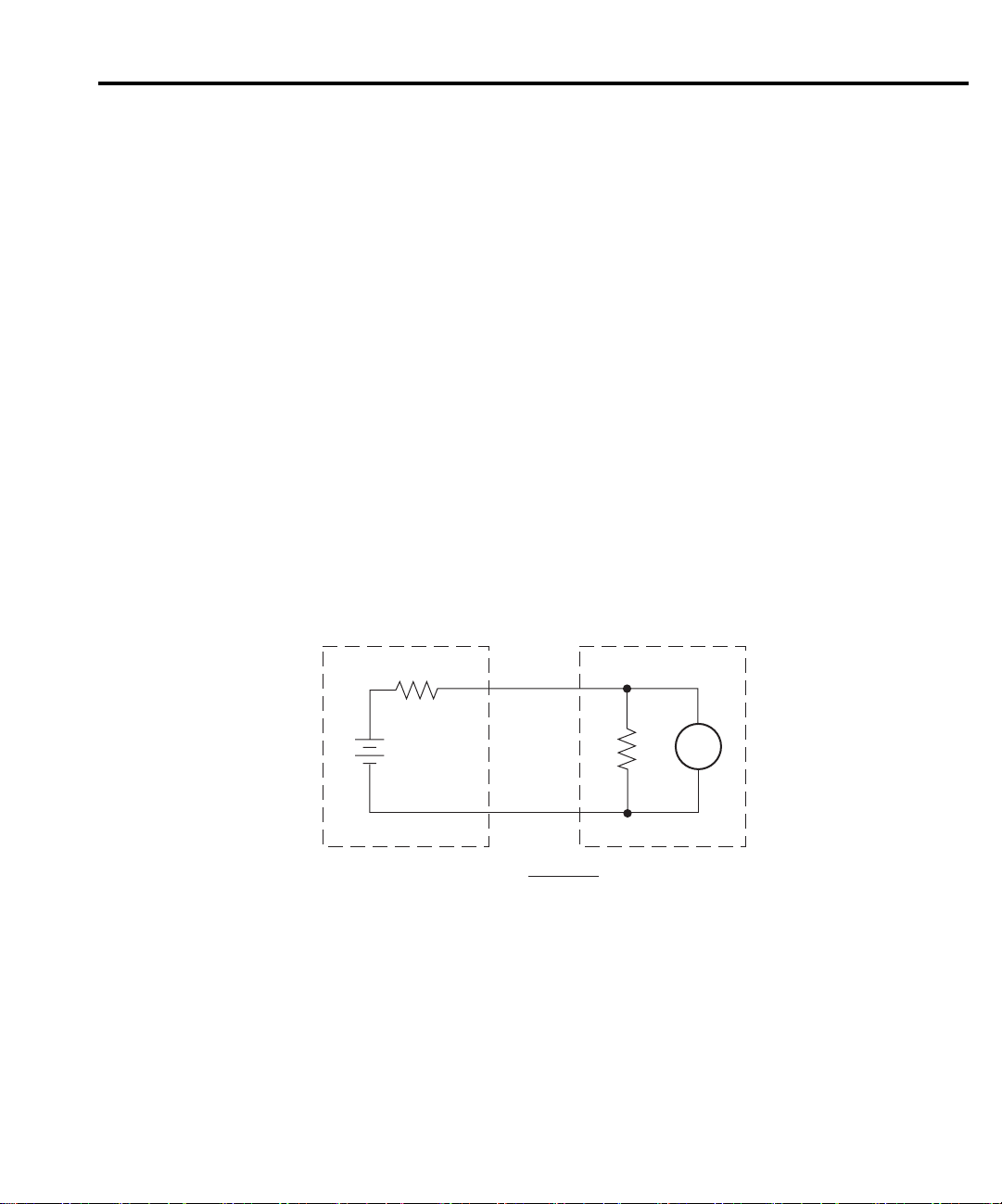
Volts and Ohms Measurements 3-9
Volts and ohms measurement considerations
NOTE Since Model 6514 uses the source I measure V (calculate R) technique to measure
resistance, measurement considerations that apply to the volts function also apply to
the ohms function.
Some considerations for making accurate volts and ohms measurements are summarized as
follows. Additional measurement considerations are covered in Appendix C. For comprehensive
information on precision measurements, refer to the Low Level Measurements handbook, which
is available from Keithley Instruments.
Loading effects
Circuit loading can be detrimental to high-impedance voltage measurements. To see how
meter loading can affect accuracy, refer to Figure 3-4. R
of the source, while R
represents the input resistance of the meter. The percent error due to
IN
loading can be calculated using the formula in the illustration. To keep the error under 0.1%, the
input resistance (R
) must be about 1000 times the value of the source resistance (RS). The input
IN
resistance of Model 6514 is >200TΩ. Therefore, to keep the error under 0.1%, the source resistance of the measured voltage must be <200GΩ.
represents the resistance component
S
Figure 3-4
Meter loading
Cable leakage resistance
Source
E
s
R
s
100R
% Error =
RS + R
S
IN
Meter
R
IN
V
In an unguarded voltage measurement, leakage current occurs in the input triax cable between
the center conductor (HI) and the inner shield (LO). This leakage resistance shunts the voltage
source to be measured. If the resistance of the source is not signif cantly less than the leakage
resistance of the cable, measurement errors will occur.
The effects of leakage resistance can be eliminated by using guard to make high impedance
voltage measurements. See “Guarding Input Cable” for more information. In general, guarding
should be used when DUT resistance is 10
9
Ω or greater.
Page 67

3-10 Volts and Ohms Measurements
Input capacitance (settling time)
The settling time of the circuit is particularly important when making volts measurements of
a source that has high internal resistance (Figure 3-5A), or when making high-resistance ohms
measurements (Figure 3-5B).
In both cases, the shunt capacitance (C) has to fully charge before an accurate voltage measurement can be made by V
mined by the RC time constant (one time constant,
of Figure 3-6 results. Therefore, it becomes necessary to wait four or f ve time constants to
achieve an accurate reading. For example, if R = 100G( and the input cable has a nominal capacitance of 10pF, the RC time constant would be 1 second. If 1% accuracy is required, a single
measurement would require at least f ve seconds.
There are two basic ways to minimize this problem: (1) keep capacitance in the system to an
absolute minimum by keeping connecting cables as short as possible, and (2) use guarding.
There is, however, a limit to how short the cable can be. Using guard can reduce these effects
by up to a factor of 1000 (see “Guarding Input Cable”).
of Model 6514. The time period for charging the capacitor is deter-
M
τ = RC), and the familiar exponential curve
Page 68
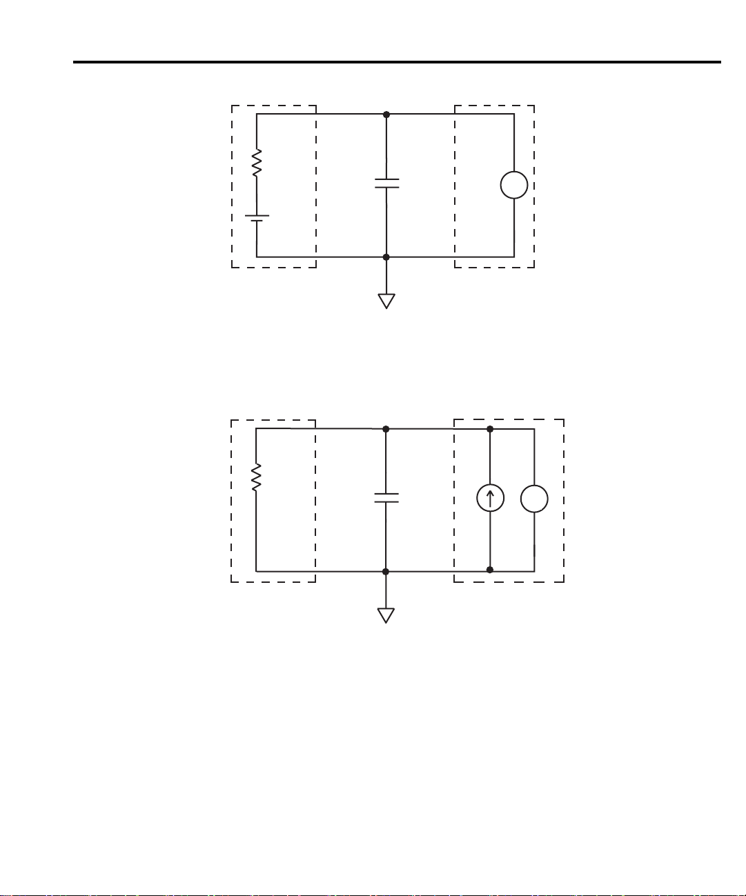
Volts and Ohms Measurements 3-11
Figure 3-5
Effects of input
capacitance
HI
R
C
E
LO
Measured
Source
6514
Voltmeter
τ = RC
A. High-Impedance Volts Measurement (Unguarded)
HI
R
C
V
M
I
S
V
M
LO
Measured
Resistance
6514
Ohmmeter
τ = RC
B. High-Impedance Ohms Measurement (Unguarded)
Page 69
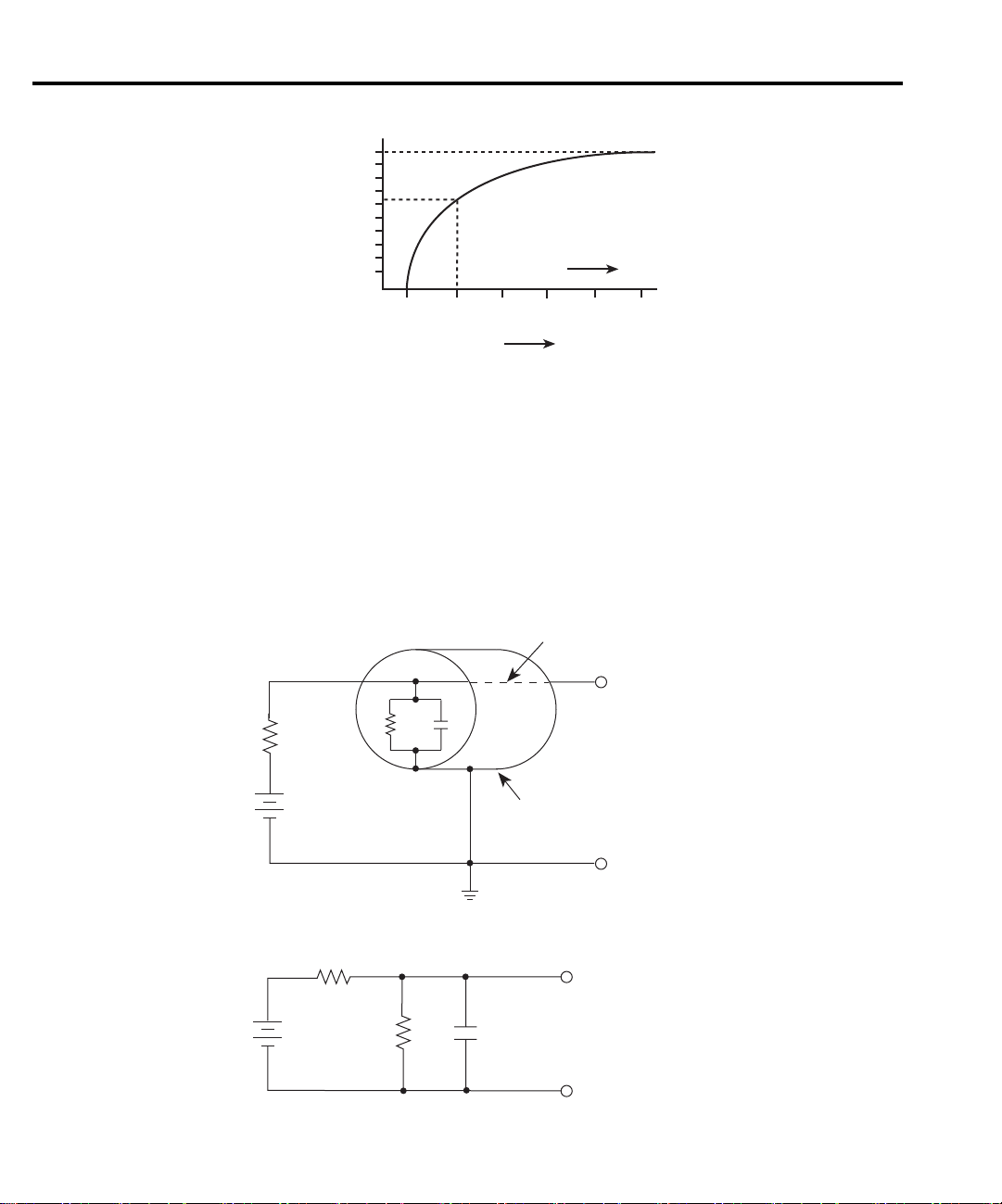
3-12 Volts and Ohms Measurements
Figure 3-6
Settling time
Guarding input cable
ments that use long input cables.
3-7. E
represents the leakage resistance and cable capacitance of the triax input cable. The equivalent
circuit shows the divider that is formed. If R
uate the voltage seen at the input of Model 6514 (see “Cable Leakage Resistance”). Also, R
the cable capacitance (C
response (see “Input Capacitance”).
Figure 3-7
Unguarded input cable
100
Percent
of Final
Value
63
Time
0
0 1.0 2.0 3.0 4.0 5.0
RC
Guarding should be used for high-impedance measurements and for low voltage measure-
To better understand the concept of guarding, review the unguarded circuit shown in Figure
and R
S
represents the resistance and voltage components of the source, and RL and CL
S
is large enough, the divider will signif cantly atten-
S
) could create a long RC time constant resulting in a slow measurement
L
Center
Source
Triax Cable
Conductor
S
and
HI
R
C
L
R
S
E
S
R
S
E
S
Equivalent Circuit
L
To 6514
Input
Inner Shield
LO
HI
R
C
L
L
To 6514
LO
Input
Page 70

Volts and Ohms Measurements 3-13
Guarding the circuit minimizes these effects by driving the inner shield of the triax cable at
signal potential, as shown in Figure 3-8. Here, a unity gain amplifier with a high input impedance and low output impedance is used. Since the center conductor (HI) and the inner shield
(Guard) of the cable are at virtually the same potential, the potential across R
rent fl ws. Also, with a zero potential across C
, there is no capacitor charging process to slow
L
is zero, so no cur-
L
down the measurement response.
For the volts and ohms functions, the input of Model 6514 places the driven guard on the
inner shield of the triax cable when GRD is enabled.
Figure 3-8
Guarded input cable
Source
Center
Triax Cable
R
C
L
R
S
E
S
L
Inner Shield
Conductor
HI
LO
A = I
6514 Input
150kΩ
Guard
Page 71

3-14 Volts and Ohms Measurements
Application
Capacitor dielectric absorption
Dielectric absorption occurs when randomly oriented permanent dipoles of molecules with a
capacitor dielectric are aligned by an applied electric f eld. After a capacitor has been disconnected from a discharge circuit, a residual charge remains on the capacitor, and a voltage will be
re-established across the capacitor terminals.
For timing and integrating applications, dielectric absorption (or a residual capacitor voltage)
can seriously degrade the accuracy of the circuit. Thus, a capacitor’s dielectric absorption must
be known and compensated for in circuits where capacitance tolerance is a signif cant factor in
circuit accuracy.
Dielectric absorption is not normally specif ed by a manufacturer since its importance is
application dependent. The parameter can be def ned as the capacitor’s discharge current at a
designated time following the initiation of a discharge cycle. The capacitor is typically charged
up to the maximum voltage that will be applied. The measurement of the discharge current is
usually made at a discharge time interval that will be used in the application of the device, or no
longer than one minute. Acceptable capacitors have current levels below a required maximum
limit.
Dielectric absorption can also be expressed as a percentage of residual voltage with respect
to a charging voltage. This ratio is determined by charging the capacitor to the rated voltage. The
capacitor is then discharged for a second time interval. Finally, the capacitor is open-circuited,
and the residual voltage across the capacitor is measured after a third time constant.
The Model 6514 is particularly useful in measuring dielectric absorption because it draws virtually no charge from the capacitor during the measurement, nor does it induce charge on the
capacitor being measured.
The test circuit in Figure 3-9A uses Keithley Model 230 as a voltage source and Model 6514
to perform the voltage measurements. Figure 3-9B shows the voltage waveform across the
capacitor during the three phases of the test.
Initially, capacitor C is charged through R
Soak time is typically one or two minutes, depending on the capacitor value. Next, the voltage
source is turned off, and the capacitor is discharged through R
sit for a few minutes with S
6514. Dielectric absorption is then calculated as follows:
% Dielectric Absorption = (Residual Voltage / Soak Voltage) × 100%
and S1 open (t3), and the residual voltage is then measured by Model
2
for the required soak time (t1 in Figure 3-9B).
1
(t2). The capacitor is allowed to
2
Page 72
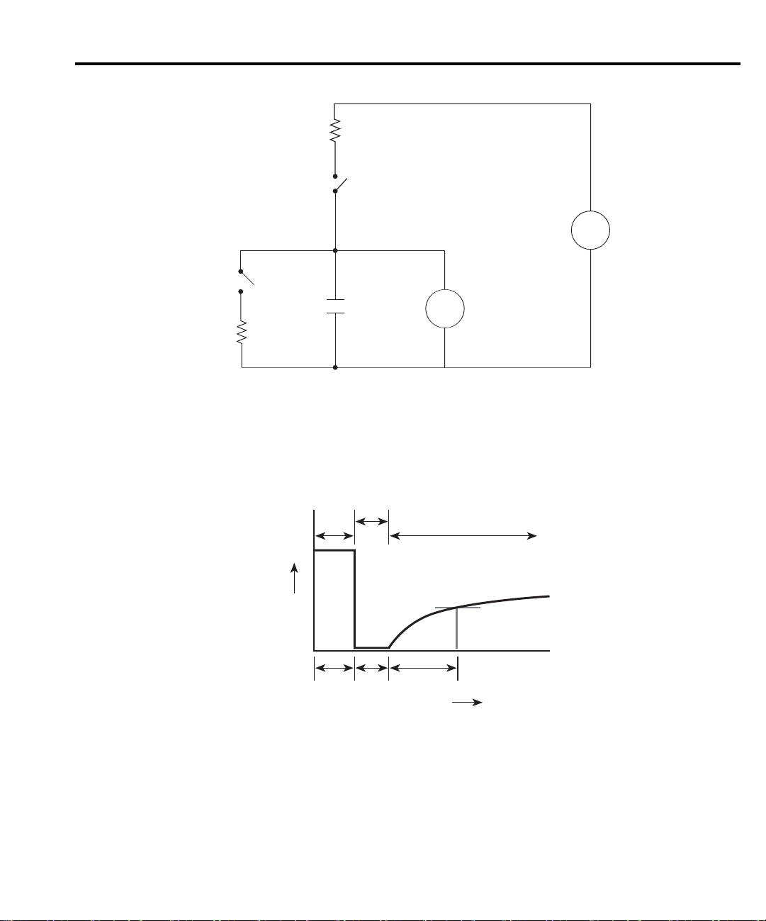
Figure 3-9
Measuring dielectric
absorption
Volts and Ohms Measurements 3-15
R
1
S
1
S
R2
+
_
V
H
M
L
0
1
6514
VOLTMETER
2
C
230
VOLTAGE SOURCE
A. Connections
Discharge
Soak Recovery
V
t
t
1
2
B. Voltage Waveform
t
3
Time
Page 73

4
Amps Measurements
• Measurement overview — Summarizes the current measurement capabilities of Model
6514.
• Amps measurement procedure — Provides the procedure to measure amps.
• High-Impedance measurement techniques — Explains non-driven guarding tech-
niques to eliminate leakage currents in high-impedance test circuits.
• SCPI programming — Covers the basic SCPI commands used for the amps function.
• Amps measurement considerations — Covers measurement considerations that apply
to amps measurements.
• Applications — Covers applications to measure diode leakage current, capacitor leak-
age current, cable insulation resistance, and surface insulation resistance.
Page 74

4-2 Amps Measurements
Measurement overview
Amps measurements — Model 6514 can make amps measurements from 100aA to 21mA
using 10 measurement ranges; 20pA, 200pA, 2nA, 20nA, 200nA, 2µA, 20µA, 200µA, 2mA,
and 20mA.
External feedback — The external feedback mode of Model 6514 can be used to measure
logarithmic currents, and re-configure the input to use non decade current ranges. Measurements using the external feedback mode are covered in Section 11.
NOTE Accuracy specifications for all measurement functions are provided in Appendix A.
Amps measurement procedure
CAUTION The maximum input voltage and current to Model 6514 is 250V peak and
21mA. Exceeding either of these values may cause damage to the instrument that is not covered by the warranty.
WARNING The maximum common-mode input voltage, which is the voltage between
the input (HI or LO) and chassis ground, is 500V peak. Exceeding this value
may create a shock hazard.
To achieve optimum precision for low-level current measurements, input bias current and
voltage burden can be minimized by performing the offset correction procedures in Section 19.
Information about these offsets are provided in “Current Measurement Considerations” (located
in this section).
NOTE After measuring high voltage or high ohms, it may take several minutes for the input
current to drop to within specif ed limits. Input current can be verif ed by placing the
protection cap on the input triax connector, and then installing the ground link
between COMMON and CHASSIS ground. With the instrument on the 20pA range
and zero check disabled, allow the reading to settle until the input bias current is
within specif cations. The specifications for input bias current are listed in
Appendix A.
Perform the following steps to measure current:
Step 1 Enable zero check and select the amps (I) function
Zero check should always be enabled before making function or connection changes. The
ZCHK key toggles zero check on and off. When on, the “ZC” or “ZZ” message is displayed. See
Section 2 for details on zero check.
The amps function is selected by pressing the I key.
Page 75

Amps Measurements 4-3
Step 2 Perform zero correction
To achieve optimum accuracy for low current measurements, it is recommended that you zero
correct the electrometer. To do so, select the 20pA range (which is the lowest range) and press
the ZCOR key until the “ZZ” message is displayed. See Section 2 for details on zero correction.
Step 3 Select a manual measurement range or enable auto range
Use the RANGE and keys to select a manual measurement range, or press AUTO to
enable auto range. With auto range enabled, the instrument will automatically go to the most
sensitive range to make the measurement. See Section 6 for details on range.
Step 4 Connect the current to be measured to the electrometer
Basic connections for amps measurements are shown in Figure 4-1.
NOTE Fundamental information on making connections to the electrometer input is pro-
vided in Section 2 (“Connection Fundamentals”).
WARNING A safety shield is required whenever a hazardous voltage (>30V) is present
on the noise shield. This can occur when the test circuit is floated above
earth ground at a hazardous voltage level (see “Floating Measurements” in
Section 2). Connections for the safety shield are shown in Figure 4-1. The
metal safety shield must completely surround the noise shield or foating test
circuit, and it must be connected to safety earth ground using #18 AWG or
larger wire.
NOTE High-impedance current measurements require special measurement techniques.
These connection techniques are covered in “High-Impedance Measurement Techniques” (located in this section).
Page 76

4-4 Amps Measurements
Figure 4-1
Connections for
amps
237-ALG-2
Cable
Red (HI)
INPUT 250V PK
INPUT PREAMP
OFF
ON
V, GUARD
(PROGRAMMABLE)
Green
(Chassis)
Black (LO)
PREAMP OUT
250V PK
GUARD
(FOLLOWS
INPUT)
(INTERNAL)
2V ANALOG
10K
OUTPUT
PREAMP
2V ANALOG
COM
!
COMMON CHASSIS
TRIGGER LINK
OUT
OUTPUT
6514 Rear Panel
LINE RATING
50, 60Hz
!
60 VA MAX
FUSE LINE
630mA
T
100 VAC
(SB)
120 VAC
220 VAC
315mAT
240 VAC
(SB)
Metal Noise Shield
Metal Safety Shield
Safety
Earth
Ground
RS232DIGITAL I/O
120
MADE IN
IEEE-488
(CHANGE IEEE ADDRESS
WITH FRONT PANEL MENU)
U.S.A.
Step 5 Disable zero check and take a reading from the display
filtering if the noise is caused by a noisy input signal and use damping if noise is caused by input
capacitance. Filtering is covered in Section 6, and damping is discussed next.
Damping
uted to a long input cable or to the capacitance of the source, or a combination of both. Enabling
damping will reduce this type of noise for current measurements. However, damping will also
slow down the response of the measurement.
If the readings are noisy, you may want to use damping and/or f ltering to reduce noise. Use
High capacitance seen at the input will increase reading noise. This capacitance can be attrib-
Perform the following steps to enable or disable damping:
1. Press DAMP to display the present state of damping.
2. Use the
or key to display ON or OFF.
3. Press ENTER.
Page 77

Amps Measurements 4-5
High impedance measurement techniques
Significant leakage could occur across a high impedance (≥1GΩ) DUT through the insulators
as shown in Figure 4-3A where R
ing just the current (I
) through R, you are also measuring the leakage current (IL). The current
R
measured by the ammeter is I
By connecting ammeter input LO to the metal mounting (guard) plate as shown in Figure
4-2B, the leakage current (I
L
ter. Therefore, the ammeter only measures I
and RL2 represent the leakage resistance. Instead of measur-
L1
+ IL.
R
) is shunted to ammeter input LO and is not measured by the amme-
.
R
Figure 4-2
High impedance
current measurements
E
A. Unguarded
E
*R = ≥1GΩ
R
L1
Metal Mounting Plate
R
L1
Metal Guard Plate
I
R
R*
I
L
Insulators
I
R
R*
R
I
L
IM = IR + I
HI
6514
L2
HI
6514
A
IM = I
A
L
LO
R
LO
B. Guarded
Page 78

4-6 Amps Measurements
Floating current measurements — As discussed in Section 3 for volts measurements,
guarding uses a conductor at essentially the same potential as input HI to drastically reduce leakage currents in high-impedance test circuits. No current can f ow when there is a 0V drop across
a leakage resistance.
For floating current measurements, ammeter input LO can be used as the guard since it totally
surrounds input HI (via the input triax cable), and is at nearly the same potential as input HI. The
actual voltage drop, known as voltage burden, depends on which measurement range is being
used. The voltage burden values are listed in the specif cations (Appendix A).
Figure 4-3A shows an unguarded f oating current measurement in a high impedance circuit.
The goal is to measure the current (I
from ammeter input LO to test circuit common. Since the ammeter drops essentially 0V, approximately 10V is dropped by R
(10V/1GΩ = 10nA). Therefore, the current that is measured by Model 6514 is the sum of the
two currents (I = I
corrupt the measurement.
Figure 4-3B shows the guarded version of the same circuit. Notice that the only difference is
that the connections to the electrometer are reversed. Resistor R
from ammeter input HI to ammeter input LO, and resistor R
ter input LO (guard) to test circuit common. As previously mentioned, the ammeter drops almost
0V. If the actual voltage drop across the ammeter is <2mV, it then follows that there is a <2mV
drop across R
that is being measured by Model 6514 is the sum of the two currents (I = I
of guarding reduced the leakage current from 10nA to <2pA. Note that the 10nA leakage current
(I
) from ammeter input LO to test circuit common still exists, but it is of no consequence since
G
it is not measured by Model 6514.
) through resistor R. However, a leakage path (RL) exists
R
. The current through RL will be approximately 10nA
L
+10nA). Obviously, if IR is a low level current, then the 10nA leakage will
R
now represents the leakage
L
represents the leakage from amme-
G
. Therefore, the current through RL is <2pA (<2mV/1GΩ = <2pA). The current
L
+ <2pA). The use
R
Page 79

Amps Measurements 4-7
Figure 4-3
Floating current
measurements
10V
A. Unguarded
+10V
10V
+10V
HI
6514
I = IR + 10nA
A
I
R
LO
R
R
L
1GΩ
10V
I
=
L
1GΩ
= 10nA
6514
LO
I = IR + <2pA
A
I
R
R
R
1GΩ
R
G
1GΩ
HI
<2mV
I
L
L
IG =
=
1GΩ
10V
1GΩ
= <2pA
= 10nA
B. Guarded
Page 80

4-8 Amps Measurements
SCPI programming
Table 4-1
SCPI commands — amps function
Commands Description Default Ref
[SENSe] SENSe Subystem:
:FUNCtion ‘CURrent’ Select Amps function. VOLT A
:DATA? Return latest “raw” reading. B
:CURRent
:DAMPing <b> Enable or disable damping. OFF
INITiate Trigger one or more readings. B
READ? Trigger and return reading(s). B
A) SENSe:FUNCtion <name>
Parameters ‘CURRent’ Amps function
‘VOLTage’ Volts function
‘RESistance’ Ohms function
‘CHARge’ Coulombs function
Note that the parameter names are enclosed in single quotes (‘). However, double quotes (“)
can instead be used. Each measurement function “remembers” its own unique range setting.
B) SENSe:DATA?
This command does not trigger a reading. It simply returns the last “raw” reading string. It
will not return the result of any instrument calculation. The reading ref ects what is applied to
the input.
To return a fresh (new) reading, you can send the INITiate command to trigger one or more
readings before sending :DATA?. Details on INITiate are provided in Section 9.
While Model 6514 is busy performing measurements, the :DATA? command will not return
the reading string until the instrument f nishes and goes into the idle state.
Page 81

NOTES The format that the reading string is returned in is set by commands in the FORMat
Subsystem (see Section 16).
If there is no reading available when :DATA? is sent, an error (-230) will occur.
The READ? command can be used to return “fresh” readings. This command triggers
and returns the readings. See Section 15 for details.
Programming example
The following command sequence will perform one zero corrected amps measurement:
*RST ‘ Return 6514 to RST defaults.
SYST:ZCH ON ‘ Enable zero check.
FUNC ‘CURR’ ‘ Select the Amps function.
CURR:RANG 20e-12 ‘ Select the 20pA range.
SYST:ZCOR ON ‘ Perform zero correction.
CURR:RANG:AUTO ON ‘ Enable auto range.
SYST:ZCH OFF ‘ Disable zero check.
READ? ‘ Trigger and return one reading.
Amps measurement considerations
Amps Measurements 4-9
Some considerations for making accurate amps measurements are summarized as follows.
Additional measurement considerations are covered in Appendix C. For comprehensive information on precision measurements, refer to the Low Level Measurements handbook, which is
available from Keithley Instruments.
Input bias current
An ideal ammeter would read 0A with an open input. In practice, however, ammeters do have
some current that f ows when the input is open. This current is known as the input bias (offset)
current and may be large enough to corrupt low current measurements.
The input bias current for Model 6514 is listed in the specif cations. Input bias current may
be reduced by performing the current offset correction procedure explained in Section 19.
Voltage burden
The input resistance of the ammeter causes a small voltage drop across the input terminals.
This voltage is known as the voltage burden. If the voltage burden is large in relation to the voltage of the measured circuit, then signif cant measurement errors will occur.
Refer to Figure 4-4 to see how voltage burden affects current measurements. Assume V
5mV and R
with zero voltage burden would measure the current source as follows:
I
M
is 5kΩ to configure a 1uA current source (5mV/5kΩ = 1µA). An ideal ammeter
S
E
S
------
R
S
5mV
------------ 1µA== =
5kΩ
is
S
Page 82
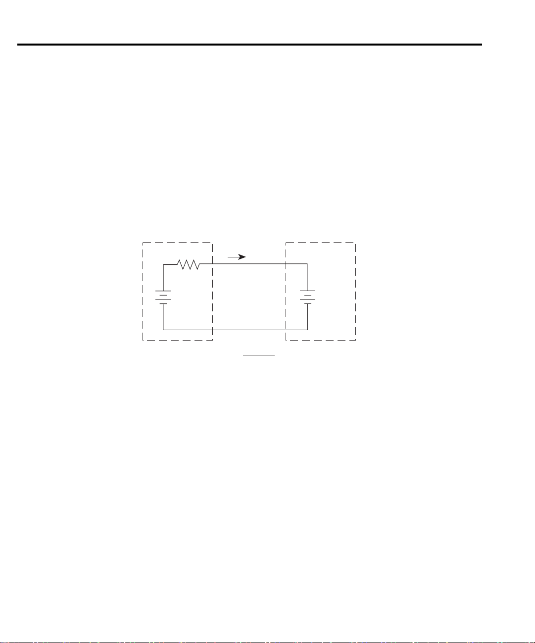
4-10 Amps Measurements
In practice however, every ammeter has a voltage burden. If the voltage burden (VB) is 1mV,
the current will be measured as follows:
VSVB–
I
--------------------
M
The 1mV voltage burden caused a 20% measurement error. Percent error in a measured read-
ing (I
) due to voltage burden can be calculated as follows:
M
IM%error
The voltage burden of Model 6514 depends on the selected range (see specif cations). Voltage
burden may be reduced by performing the offset correction procedure in Section 19.
5mV 1mV–
R
------------------------------- 0.8µA== =
S
100%
---------------------=
()
V
S/VB
5kΩ
Figure 4-4
Voltage burden
considerations
Noise
+
-
Source
V
s
R
s
I
VS - V
I
=
M
B
R
S
+
-
Meter
V
(Voltage
Burden)
B
Noise can seriously affect sensitive current measurements. The following paragraphs discuss
how source resistance and input capacitance affect noise performance.
Source resistance
The source resistance of the DUT will affect the noise performance of current measurements.
As the source resistance is reduced, the noise gain of the ammeter will increase, as we will now
discuss.
Figure 4-5 shows a simplif ed model of the feedback ammeter. R
source resistance and source capacitance, V
age. Finally, R
and CF are the feedback resistance and capacitance respectively.
F
is the source voltage, and V
S
The source noise gain of the circuit can be given by the following equation:
and CS represents the
S
is the noise volt-
NOISE
Output V
NOISE
Note that as R
Input V
decreases in value, the output noise increases. For example, when RF = RS,
S
NOISE
1 RF/R
+()=
S
the input noise is multiplied by a factor of two. Since decreasing the source resistance can have
a detrimental effect on noise performance, there are usually minimum recommended source
resistance values based on measurement range. Table 4-2 summarizes minimum recommended
Page 83
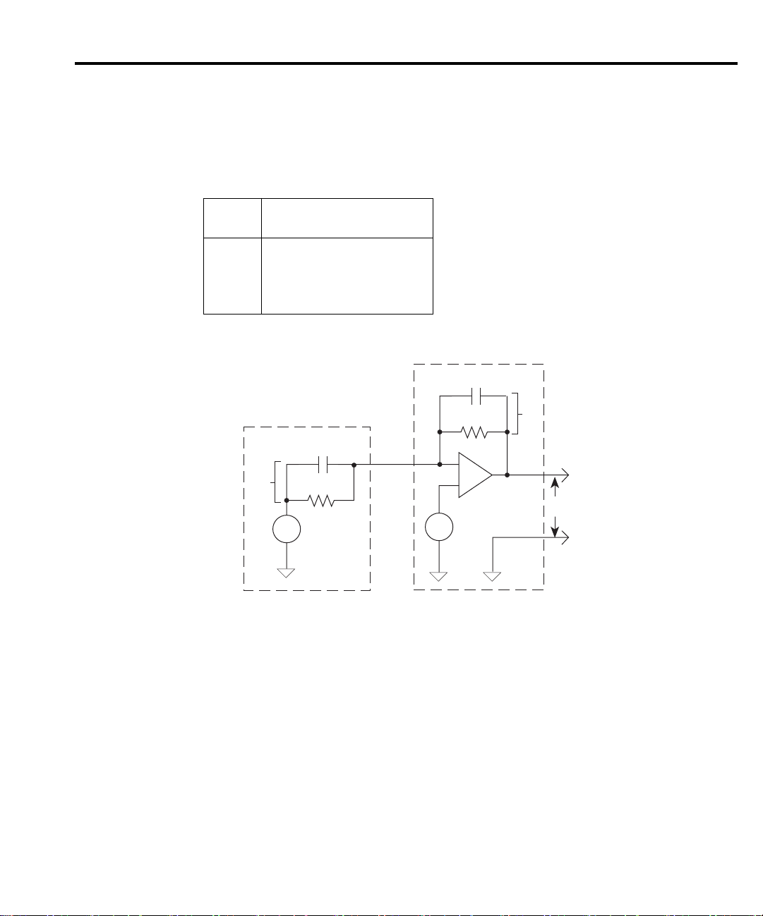
Amps Measurements 4-11
source resistance values for various measurement ranges. Note that the recommended source
resistance varies by measurement range because the R
value also depends on the measurement
F
range.
Table 4-2
Minimum recommended source resistance values
Minimum Recommended
Range
Source Resistance
pA 1GΩ to 100GΩ
nA 1MΩ to 100MΩ
µA 1kΩ to 100kΩ
mA 1Ω to 100Ω
Figure 4-5
Source resistance
and capacitance
Z
S
Current Source
C
F
R
F
C
S
-
R
S
V
S
+
V
noise
Model 6514 Ammeter
Z
F
V
O
Page 84

4-12 Amps Measurements
Source capacitance
DUT source capacitance will also affect the noise performance of the Model 6514 ammeter.
In general, as source capacitance increases, the noise also increases. To see how changes in
source capacitance can affect noise gain, again refer to the simplif ed ammeter model in Figure
4-5. The elements of interest for this discussion are the capacitance, C
itance C
gain formula must be modif ed as follows:
. Taking into account the capacitive reactance of these two elements, the previous noise
F
and the feedback capac-
S
Output V
Here, Z
NOISE
represents the feedback impedance made up of CF and RF, while ZS is the source
F
impedance formed by R
Z
-------------------------------------------------=
F
2πfRFC
()
Input V
NOISE
and CS. Furthermore,
S
R
F
2
1+[]
F
1ZF/Z
+()=
S
and,
R
Z
-------------------------------------------------=
S
Note that as C
Again, at the point where Z
The maximum value of source capacitance (C
S
2πfRSC
()
2
1+[]
S
increases in value, Z
S
= ZF, the input noise is amplif ed by a factor of two.
S
decreases in value, thereby increasing the noise gain.
S
) for Model 6514 ammeter is 10,000pF. You
S
can, however, usually measure at higher source capacitance values by inserting a resistor in
series with the ammeter input, but remember that any series resistance will increase the voltage
burden by a factor of I
IN RSERIES
. For example, the range of resistance listed in Table 4-2 will
result in voltage burden values in range of 1mV to 1V. A useful alternative to a series resistor is
a series diode, or two diodes in parallel back-to-back. The diodes can be small-signal types and
should be in a light-tight enclosure.
Page 85
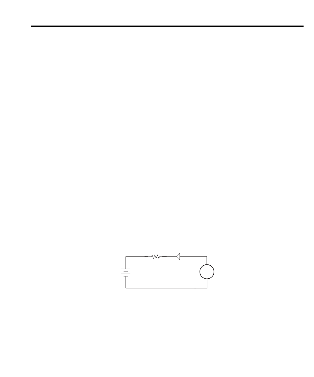
Applications
The following applications require an external voltage source. The Keithley Model 230 volt-
age source is fully programmable and can source up to 100V at 100mA.
With the proper use of external triggering between Models 6514 and 230, the tests can be
automated. All of the applications require a bias time or delay, which can be provided by the
delay feature of Model 6514. When Model 6514 is triggered, a measurement will not be performed until the delay period expires.
NOTE External triggering and delay are covered in Section 9.
Diode leakage current
Figure 4-6 shows how to measure the leakage current for a diode. By sourcing a positive voltage, the leakage current through the diode will be measured. Note that if you source a negative
voltage, you will forward bias the diode. Resistor R is used to limit current in the event that the
diode shorts out or it becomes forward biased. Select a value of R that will limit current to 20mA
or less.
A profile for leakage current can be developed by measuring current at various voltage levels.
For example, you can program Model 230 to source from 1 to 10V in 1V steps. With the proper
use of external triggering, Model 6514 will perform a current measurement on each voltage step.
To ensure that the voltage is settled before each current measurement, you can program Model
6514 for a delay. For example, if you program Model 6514 for a one second delay, each measurement will be performed after the voltage step is allowed to settle for one second. The current
measurements can be stored in the buffer.
Amps Measurements 4-13
Figure 4-6
Connections; diode
leakage current test
NOTE Buffer operation is covered in Section 8.
Diode
230
V-Source
R
+
HI
-
LO
Equivalent Circuit
HI
LO
A
6514
Ammeter
Page 86
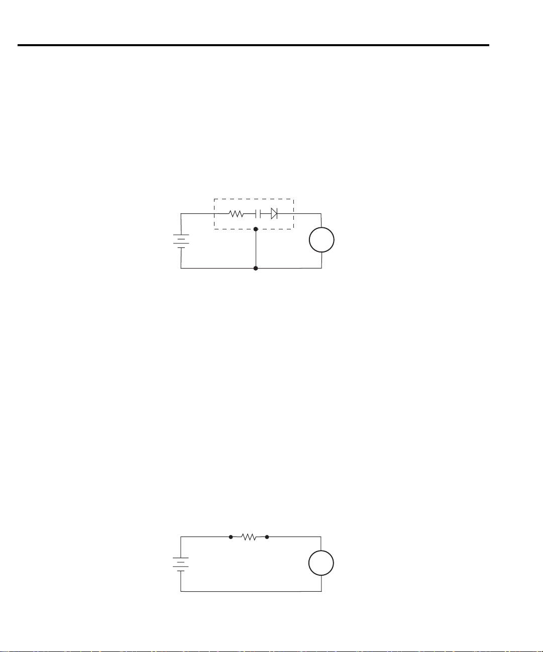
4-14 Amps Measurements
Capacitor leakage current
Figure 4-7 shows how to measure the leakage current for a capacitor. The magnitude of the
leakage is dependent on the type of dielectric and the applied voltage. A resistor and a diode are
used to limit noise for the measurement.
For this test, a f xed bias voltage is to be applied to the capacitor for a specif ed time to allow
the capacitor to fully charge (current decays exponentially with time). The leakage current is
then measured. After the measurement, the voltage source is set to output 0V for a specif ed time
to allow the capacitor to discharge.
Figure 4-7
Connections; capacitor
leakage current test
V-Source
230
+
HI
-
LO
Equivalent Circuit
HI
LO
A
6514
Ammeter
Cable insulation resistance
NOTE For this test, Model 6514 uses the source voltage, measure current method to
insulator between the shield and the inner conductor is being measured. The cable sample should
be kept as short as possible to minimize input capacitance to the ammeter.
the charging effects of cable capacitance to stabilize. The current is then measured. Cable resistance (R) can then be calculated as follows:
Figure 4-8
Connections; cable
insulation resistance
test
determine resistance. Once a current measurement is performed, resistance can be
calculated.
Figure 4-8 shows how to measure the insulation resistance of a cable. The resistance of the
For this test a f xed bias voltage is applied across the insulator for a specif ed time to allow
R = V/I
where; V is the sourced bias voltage
I is the measured current
HI
LO
A
6514
Ammeter
230
V-Source
+
HI
-
LO
Cable
Resistance
Equivalent Circuit
Page 87
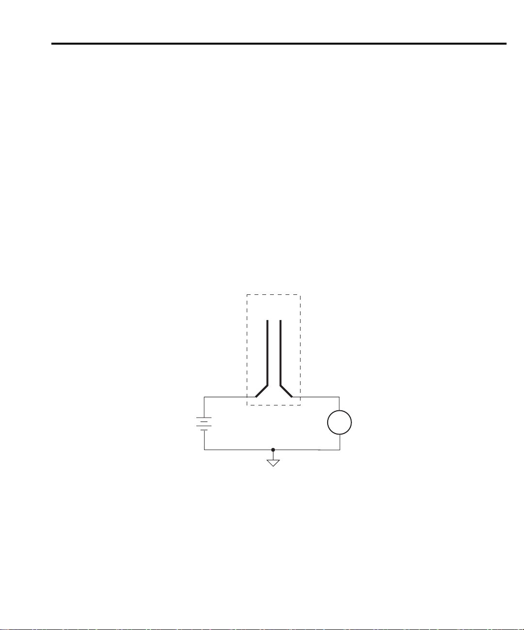
Surface insulation resistance (SIR)
NOTE For this test, Model 6514 uses the source voltage, measure current method to
determine resistance. Once a current measurement is performed, resistance can be
calculated.
Figure 4-9 shows how to measure the insulation resistance between PC board traces. Note
that the drawing shows a "Y" test pattern for the measurement. This is a typical test pattern for
SIR tests.
A bias voltage (typically 50V) is applied to the test pattern for a specif ed time (typically one
second) to polarize the test pattern. The test voltage (typically 100V) is then applied and, after
a specified time (typically one second), Model 6514 measures the current. Sur ace insulation
resistance can now be calculated as follows:
SIR = V/I
where; V is the sourced test voltage
I is the measured current
Amps Measurements 4-15
Figure 4-9
Connections; surface
insulation resistance
test
230
V-Source
PC Board
Test Pattern
+
HI
-
LO
Equivalent Circuit
HI
LO
A
6514
Picommeter
Page 88

5
Coulombs Measurements
• Measurement overview — Summarizes the charge measurement capabilities of the
Model 6514.
• Auto discharge — Explains how to use the auto discharge feature of Model 6514.
• Coulombs measurement procedure — Provides the procedure to measure coulombs.
• SCPI programming — Covers the basic SCPI commands used for the coulombs
function.
• Amps measurement considerations — Covers measurement considerations that apply
to coulombs measurements.
• Application — Summarizes an application to measure capacitance.
Page 89

5-2 Coulombs Measurements
Measurement overview
Coulombs measurements — Model 6514 can make coulombs measurements from 10fC to
2.1µC using four measurement ranges; 20nC, 200nC, 2µC, and 20µC.
In the coulombs function, an accurately known capacitor is placed in the feedback loop of the
amplifier so that the oltage developed is proportional to the integral of the input current in
accordance with the following formula:
1
----
V
C
Where; V is the voltage
The voltage is scaled and displayed as charge.
External feedback — The external feedback mode of Model 6514 can be used to measure
non-standard charge ranges. Measurements using the external feedback mode are covered in
Section 11.
NOTE Accuracy specifications for all measurement functions are provided in Appendix A.
Auto discharge
Model 6514 has an auto discharge feature for the coulombs function. When enabled, auto discharge resets the charge reading to zero when the specif ed charge level is reached. After the integrator resets, the charge measurement process simply restarts at zero. The charge reading resets
every time the specif ed charge level is reached.
When auto discharge is disabled, you can use zero check to reset the integrator.
Perform the following steps to set an auto discharge level and enable it:
Q
----==
itd
∫
C
C is the known capacitance
Q is the charge
1. Press SHIFT and then AUTO-DIS to display the present auto discharge level.
2. Use the cursor keys (
ity, place the cursor on the “+” or “-” sign and press
cursor on the range indicator and use the
3. With the desired auto discharge level displayed, press ENTER.
NOTE Pressing SHIFT and then AUTO-DIS a second time disables auto discharge
(“DISCHRG OFF” displayed brief y).
and ) and ( and ) to enter a discharge level. To change polar-
or . To change range, place the
and keys.
Page 90

Coulombs measurement procedure
CAUTION The maximum input voltage and current to Model 6514 is 250V peak and
21mA. Exceeding either of these values may cause damage to the instrument that is not covered by the warranty.
WARNING The maximum common-mode input voltage, which is the voltage between
the input (HI or LO) and chassis ground, is 500V peak. Exceeding this value
may create a shock hazard.
NOTE After measuring high voltage in the volts function, it may take several minutes for
input current to drop to within specif ed limits. Input current can be verif ed by placing the protection cap on the input triax connector, and then installing the ground link
between COMMON and CHASSIS ground. With the instrument on the 20pA range
and zero check disabled, allow the reading to settle until the input bias current is
within specif cations. The specifications for input bias current are listed in
Appendix A.
Perform the following steps to measure charge:
Step 1 Enable zero check and select the coulombs (Q) function
Zero check should always be enabled before making function or connection changes. The
ZCHK key toggles zero check on and off. When on, the “ZC” or “ZZ” message is displayed. See
Section 2 for details on zero check.
Coulombs Measurements 5-3
The coulombs function is selected by pressing the Q key.
Step 2 Select a manual measurement range or enable auto range.
Use the RANGE and keys to select a manual measurement range, or press AUTO to
enable auto range. With auto range enabled, the instrument will auto range between the HIGH
range group (2µC and 20µC) or the LO W range group (20nC and 200nC). To select the HIGH
range group, press SHIFT and then the RANGE key. To select the LOW range group, press
SHIFT and then the RANGE key. See Section 6 for details on range.
Step 3 If desired, set and enable auto discharge
See “Auto Discharge” to set an auto discharge level and enable it.
Step 4 Connect the input cable to Model 6514 (open input)
Make sure that the test circuit is not connected to the input.
Step 5 Disable zero check and press the REL key
When zero check is turned off, a charge may be induced on the input. Pressing the REL key
zeroes the display. See “Zero Check Hop” in “Coulombs Measurement Considerations” (in this
section). Details on Relative are provided in Section 7.
NOTE If the zeroed reading drifts signif cantly after REL is enabled, disable REL and toggle
zero check on and off until drift is minimized. Enable zero check and repeat Step 5.
Page 91

5-4 Coulombs Measurements
Step 6 Connect the charge to be measured to the electrometer
Basic connections for amps measurements are shown in Figure 5-1.
NOTE See “Connection Basics” in Section 2 for fundamental information on making con-
nections to the electrometer input.
Figure 5-1
Typical connections
for coulombs
Red (HI)
Metal Noise Shield
(Optional)
237-ALG-2
Cable
Black (LO)
Input LO connected
to shield
!
INPUT 250V PK
INPUT PREAMP
OFF
ON
V, GUARD
(PROGRAMMABLE)
PREAMP OUT
GUARD
(FOLLOWS
INPUT)
250V PK
(INTERNAL)
2V ANALOG
10K
OUTPUT
PREAMP
2V ANALOG
COM
COMMON CHASSIS
TRIGGER LINK
OUT
OUTPUT
LINE RATING
50, 60Hz
!
60 VA MAX
FUSE LINE
630mA
T
(SB)
315mAT
(SB)
100 VAC
120 VAC
220 VAC
240 VAC
RS232DIGITAL I/O
120
6514 Rear Panel
Step 7 Take the charge reading from the display
MADE IN
IEEE-488
(CHANGE IEEE ADDRESS
WITH FRONT PANEL MENU)
U.S.A.
If using auto discharge, use the REL key to zero the display when the integrator resets.
Remember that Rel was enabled in Step 5. Therefore, you will have to press REL twice. The first
press disables Rel, and the second press re-enables it to zero the display. See “Auto Discharge
Hop” in “Coulombs Measurement Considerations” (in this section).
Page 92

SCPI programming
Table 5-1
SCPI commands — coulombs function
Commands Description Default Ref
[SENSe] SENSe Subystem:
:FUNCtion ‘CHARge’ Select coulombs function. VOLT A
:DATA? Return latest “raw” reading. B
:CHARge
:ADIScharge Auto discharge:
[:STATe] <b> Enable or disable auto discharge. OFF
:LEVel <NRf> Set auto discharge level; -2.1e-5 to 2.1e-5. 2e-6
INITiate Trigger one or more readings. B
READ? Trigger and return reading(s). B
Coulombs Measurements 5-5
A) SENSe:FUNCtion <name>
Parameters ‘CHARge’ Coulombs function
‘CURRent’ Amps function
‘VOLTage’ Volts function
‘RESistance’ Ohms function
Note that the parameter names are enclosed in single quotes (‘). However, double quotes (“)
can instead be used. Each measurement function “remembers” its own unique range setting.
B) SENSe:DATA?
This command does not trigger a reading. It simply returns the last “raw” reading string. It
will not return the result of any instrument calculation. The reading ref ects what is applied to
the input.
To return a fresh (new) reading, you can send the INITiate command to trigger one or more
readings before sending :DATA?. Details on INITiate are provided in Section 9.
While Model 6514 is busy performing measurements, the :DATA? command will not return
the reading string until the instrument f nishes and goes into the idle state.
Page 93

5-6 Coulombs Measurements
NOTES The format that the reading string is returned in is set by commands in the FORMat
Subsystem (see Section 16).
If there is no reading available when :DATA? is sent, an error (-230) will occur.
The READ? command can be used to return “fresh” readings. This command triggers
and returns the readings. See Section 15 for details.
Programming example
The following command sequence will perform one coulombs measurement:
*RST ‘ Return 6514 to RST defaults.
SYST:ZCH ON ‘ Enable zero check.
FUNC ‘CHAR’ ‘ Select the Coulombs function.
CHAR:RANG:AUTO ON ‘ Enable auto range.
SYST:ZCH OFF ‘ Disable zero check.
CALC2:NULL:STAT ON ‘ Enable Rel to zero the display.
READ? ‘ Trigger and return one reading.
‘ Connect input cable.
‘ Connect charge circuit to DUT.
Coulombs measurement considerations
Some considerations for making accurate Coulombs measurements are summarized as follows. Additional measurement considerations are covered in Appendix C. For comprehensive
information on precision measurements, refer to the Low Level Measurements handbook, which
is available from Keithley Instruments.
Input bias current
A primary consideration when making charge measurements is the input bias (offset) current
of the integrating amplif er. Any such current is integrated along with the input signal and
reflected in the nal reading. Model 6514 has a maximum input bias of 4fA for charge at T
(temperature at time of calibration). This input offset translates into a charge of 4fC per second
at the T
rect value.
Input bias current may be reduced by performing the offset correction procedure explained
in Section 19.
temperature. This value must be subtracted from the f nal reading to obtain the cor-
CAL
External voltage source
When using an external voltage source, the input current should be limited to less than 1mA
by placing a resistor in series with the high input lead. The value of this resistor should be at
least:
R = 1000 × V (ohms)
where; V is the voltage across the resistor, or the compliance of the current being integrated.
CAL
Page 94

Zero check hop and auto discharge hop
den change in the charge reading and is known as zero check hop. This sudden change in charge
also occurs when the auto discharge feature resets the charge reading to zero. This hop in charge
can be eliminated by taking a reading the instant zero check is disabled or when an auto discharge occurs, and subtracting it from all subsequent readings. A better way to deal with this hop
in charge is to enable Rel immediately after zero check is disabled or when auto discharge resets
the charge reading. This action nulls out the charge reading caused by the hop.
Application
Capacitance measurements
used to limit current. Select a value for R1 that will limit current to ≤100mA, and select a value
for R2 that will limit current to ≤20mA.
waiting sufficient time for the capacitor to fully cha ge, open switch S1 and close switch S2 to
measure the charge. The capacitance can now be calculated as follows:
Coulombs Measurements 5-7
Using the zero check feature (going from the enabled state to the disabled state) causes a sud-
Figure 5-2 shows a general test circuit to measure a capacitor (C). Resistors R1 and R2 are
When switch S1 is closed, the Keithley Model 230 voltage source charges the capacitor. After
Figure 5-2
Measuring
capacitors
C = Q/V
where; C is the capacitance (in farads)
Q is the measured charge (in coulombs)
V is the voltage used to charge the capacitor
S1 S2
R1 R2
230
V-Source
C = Q/V
Q
C
6514
Page 95

6
Range, Units,
Digits, Rate, and Filters
• Range, units, and digits — Provides details on measurement range, reading units, and
display resolution selection. Includes the SCPI commands for remote operation.
• Rate — Provides details on reading rate selection. Includes the SCPI commands for
remote operation.
• Filters — Explains how to configure and control the digital and median f lters. Includes
the SCPI commands for remote operation.
Page 96

6-2 Range, Units, Digits, Rate, and Filters
Range, units, and digits
Range
The ranges for each measurement function are listed in Table 6-1. The range setting (f xed or
AUTO) is remembered by each function.
Table 6-1
Measurement ranges
V I Ω Q
2V 20pA 2kΩ 20nC
20V 200pA 20kΩ 200nC
200V 2nA 200kΩ 2µC
20nA 2MΩ 20µC
200nA 20MΩ
2uA 200MΩ
20uA 2GΩ
200uA 20GΩ
2mA 200GΩ
20mA
The full scale readings for every measurement range are 5% over range. For example, on the
20V range, the maximum input voltage is ± 21V. Input values that exceed the maximum readings
cause the overfl w message (“OVERFL0W”) to be displayed.
Manual ranging
To select a range, press the RANGE or key. The instrument changes one range per
key-press. The selected range is displayed momentarily. If the instrument displays the “OVERFLOW” message on a particular range, select a higher range until an on-range reading is displayed. Use the lowest range possible without causing an overfl w to ensure best accuracy and
resolution.
Autoranging
When using autorange, the instrument automatically goes to the most sensitive available
range to measure the applied signal. Up-ranging occurs at 105% of range, while down-ranging
occurs at the range value. For example, if on the 20V range, the instrument will go up to the
200V range when the input signal exceeds 21V. While on the 200V range, the instrument will
go down to the 20V range when the input level goes to 20V.
The AUTO key toggles the instrument between manual ranging and autoranging. The AUTO
annunciator turns on when autoranging is selected. To disable autoranging, press AUTO or the
RANGE
range.
or key. Pressing AUTO to disable autoranging leaves the instrument on the present
Page 97

Range, Units, Digits, Rate, and Filters 6-3
Every time an autorange occurs, a search for every available range of the selected function is
performed. The time it takes to perform the search could slow down range change speed significantly. For V, I and ( measurements, upper and/or lower autorange limits can be set to reduce
search time. For Q measurements, the instrument will only autorange between the two higher
charge ranges (high range group), or between the two lower charge ranges (low range group).
NOTE Range limits and groups are not in effect for manual ranging. Every range is accessi-
ble with manual range selection.
Autorange limits for V, I and Ω
Search time for V, I and Ω can be reduced by setting upper and/or lower autorange limits. For
example, if you know the maximum input will be around 1µA, you can set the upper current
range limit to 2µA. This eliminates the 20µA, 200µA, 2mA and 20mA ranges from the search,
therefore, increasing the range change speed. Should the input exceed 2.1µA, the “OVERFLOW” message will be displayed.
Perform the following steps to set upper and/or lower autorange limits.
1. Select the V, I or Ω function.
2. Press SHIFT and then one of the following RANGE keys:
a. Press the RANGE
b. Press the RANGE
3. Use the RANGE
key to display the present UPPER range limit.
key to display the present LOWER range limit.
and keys to display the desired limit.
4. Press ENTER.
NOTE If you attempt to select an incompatible range limit, it will be ignored and “TOO
LARGE” or “TOO SMALL” will be displayed brief y. For example, if the lower range
limit is 20V, trying to set the upper limit to 2V will result in the “TOO SMALL” error.
Autorange groups for Q
To optimize range change speed for charge measurements, the instrument will only autorange
between two ranges. With the high range group selected, the instrument can only autorange
between the 2µC and 20µC ranges. With the low range group selected, the instrument can only
autorange between the 20nC and 200nC ranges.
If the HIGH range group is presently selected and the instrument is on the 20nC or 200nC
range (autorange disabled), pressing the AUTO range key will initially select the 2µA range and
then enable autorange. If the range group is then changed to LOW, the instrument will initially
go to the 200nC range with autorange enabled. Therefore, the instrument will always stay within
the selected range group with autorange enabled.
NOTE With the low range group selected, the “OVERFLOW” message will be displayed
when the input signal exceeds 210nC.
Perform the following steps to select autorange group for Q:
1. Select the Q function.
2. Press Shift and then one of the follow RANGE keys:
a. Press the RANGE
b. Press the RANGE
key to select the HIGH range group (2µC and 20µC).
key to select the LOW range group (20nC and 200nC).
Page 98

6-4 Range, Units, Digits, Rate, and Filters
Units
Readings can be displayed using engineering (ENG) units (i.e. 1.236 MΩ) or scientif c (SCI)
notation (i.e. 1.236E+06Ω). Perform the following steps to change the units setting:
1. Press SHIFT and then DIGIT to display the present units setting (ENG or SCI).
2. Press the RANGE
3. Press ENTER.
NOTE 1. The units setting can only be changed from the front panel (no remote operation).
2. Scientific notation provides more resolution on small values than engineering
units.
or key to display the desired units setting.
Digits
The DIGIT key sets display resolution for Model 6514. Display resolution can be set from
3½ to 6½ digits. This single global setting affects display resolution for all measurement
functions.
To set display resolution, press (and release) the DIGIT key until the desired number of digits
is displayed.
NOTE Changing the integration rate changes display resolution, but changing display reso-
lution does not change the rate setting (see RATE for details).
SCPI programming - range and digits
Table 6-2
SCPI commands — range and digits
Commands Description Default
For Range:
[:SENSe] SENSe Subsystem:
:VOLTage Measure voltage:
:RANGe Range selection:
[:UPPer] <n> Specify expected reading; -210 to 210 (V). 20V
: AUTO <b> Enable or disable autorange. (see Note)
:ULIMit <n> Specify upper range limit for autorange; -210 to 210 (V). 200V
:LLIMit <n> Specify lower range limit for autorange; -210 to 210 (V). 2V
Page 99

Range, Units, Digits, Rate, and Filters 6-5
Table 6-2 (cont.)
SCPI commands — range and digits
Commands Description Default
:CURRent Measure current:
:RANGe Range selection:
[:UPPer] <n> Specify expected reading; -0.021 to 0.021 (A). 200µA
: AUTO <b> Enable or disable autorange. (see Note)
:ULIMit <n> Specify upper range limit for autorange; -0.021 to 0.021 (A). 20mA
:LLIMit <n> Specify lower range limit for autorange; -0.021 to 0.021 (A). 20pA
:RESistance Measure resistance:
:RANGe Range selection:
[:UPPer] <n> Specify expected reading; 0 to 2.1e11 (Ω). 200kΩ
: AUTO <b> Enable or disable autorange. (see Note)
:ULIMit <n> Specify upper range limit for autorange; 0 to 2.1e11 (Ω). 200GΩ
:LLIMit <n> Specify lower range limit for autorange; 0 to 2.1e11 (Ω). 2kΩ
:CHARge Measure charge:
:RANGe Range selection:
[:UPPer] <n> Specify expected reading; -21e-6 to 21e-6 (C). 200nC
: AUTO <b> Enable or disable autorange. (see Note)
:LGRoup <name> Select autorange group; HIGH or LOW HIGH
For Digits:
DISPlay DISPlay Subsystem:
:DIGITs <n> Set display resolution; 4 to 7, where: 6
4 = 3½-digit resolution
5 = 4½-digit resolution
6 = 5½-digit resolution
7 = 6½-digit resolution
Note: Rational numbers can be used. For example, to set 4
resolution, send a value of 4.5 (the 6514 rounds it to 5).
Note: *RST default is ON and SYSTem:PRESet default is OFF.
Programming example — range and digits
The following command sequence selects the 200V range and sets display resolution to 3:
*RST ‘ Restore RST defaults.
VOLT:RANG 200 ‘ Set V function to 200V range.
DISP:DIG 3.5 ‘ Set display resolution to 3½ digits.
Page 100

6-6 Range, Units, Digits, Rate, and Filters
Rate
The RATE key selects the integration time of the A/D converter. This is the period of time the
input signal is measured. The integration time affects the amount of reading noise, as well as the
ultimate reading rate of the instrument. The integration time is specif ed in parameters based on
a number of power line cycles (NPLC), where 1 PLC for 60Hz is 16.67msec (1/60) and 1 PLC
for 50Hz (and 400Hz) is 20msec (1/50).
In general, Model 6514 has a parabola-like shape for its speed vs. noise characteristics and is
shown in Figure 6-1. Model 6514 is optimized for the 1 PLC to 10 PLC reading rate. At these
speeds (lowest noise region in the graph), Model 6514 will make corrections for its own internal
drift and still be fast enough to settle a step response <100ms.
Figure 6-1
Speed vs. noise
characteristics
Voltage
Noise
Lowest
noise
region
166.7µs 16.67ms 166.67ms
Integration Time
The rate setting is global for all measurement functions. Therefore, it does not matter what
function is presently selected when you set rate.
There are two ways to set rate. You can select slow, medium, or fast by using the RATE key,
or you can set the number of power cycles from the NPLC menu that is accessed by pressing
SHIFT and then NPLC.
Rate Key — The RATE key selections are explained as follows:
• SLOW — Selects the slowest front panel integration time (6 PLC for 60 Hz or 5 PLC
for 50 Hz) and sets display resolution to 5½-digit resolution. The SLOW rate provides
better noise performance at the expense of speed.
• MED — Selects the medium integration time (1 PLC) and sets display resolution to
5½-digit resolution. Select the MED rate when a compromise between noise performance and speed is acceptable.
•FAST — Selects the fastest front panel integration time (0.1 PLC) and sets display resolution to 4½-digit resolution. Select the FAST rate if speed is of primary importance (at
the expense of increased reading noise).
To change the rate setting, press (and release) the RATE key until the desired rate annunciator
(SLOW, MED or FAST) is displayed.
 Loading...