

Page 1

Model 6220 DC Current Source
A GREATER MEASURE OF CONFIDENCE
Model 6221 AC and DC Current Source
User’s Manual
622x-900-01 Rev. B / June 2005
Test Equipment Depot - 800.517.8431 - 99 Washington Street Melrose, MA 02176 - TestEquipmentDepot.com
Page 2

WARRANTY
Keithley Instruments, Inc. warrants this product to be free from defects in material and workmanship for a
period of 1 year from date of shipment.
Keithley Instruments, Inc. warrants the following items for 90 days from the date of shipment: probes, cables,
rechargeable batteries, diskettes, and documentation.
During the warranty period, we will, at our option, either repair or replace any product that proves to be defective.
To exercise this warranty, write or call your local Keithley representative, or contact Keithley headquarters in
Cleveland, Ohio. You will be given prompt assistance and return instructions. Send the product, transportation
prepaid, to the indicated service facility. Repairs will be made and the product returned, transportation prepaid.
Repaired or replaced products are warranted for the balance of the original warranty period, or at least 90 days.
LIMITATION OF WARRANTY
This warranty does not apply to defects resulting from product modification without Keithley’s express written
consent, or misuse of any product or part. This warranty also does not apply to fuses, software, non-rechargeable
batteries, damage from battery leakage, or problems arising from normal wear or failure to follow instructions.
THIS WARRANTY IS IN LIEU OF ALL OTHER WARRANTIES, EXPRESSED OR IMPLIED, INCLUDING ANY IMPLIED WARRANTY OF MERCHANTABILITY OR FITNESS FOR A PARTICULAR USE.
THE REMEDIES PROVIDED HEREIN ARE BUYER’S SOLE AND EXCLUSIVE REMEDIES.
NEITHER KEITHLEY INSTRUMENTS, INC. NOR ANY OF ITS EMPLOYEES SHALL BE LIABLE
FOR ANY DIRECT, INDIRECT, SPECIAL, INCIDENTAL OR CONSEQUENTIAL DAMAGES ARISING
OUT OF THE USE OF ITS INSTRUMENTS AND SOFTWARE EVEN IF KEITHLEY INSTRUMENTS,
INC., HAS BEEN ADVISED IN ADVANCE OF THE POSSIBILITY OF SUCH DAMAGES. SUCH
EXCLUDED DAMAGES SHALL INCLUDE, BUT ARE NOT LIMITED TO: COSTS OF REMOVAL
AND INSTALLATION, LOSSES SUSTAINED AS THE RESULT OF INJURY TO ANY PERSON, OR
DAMAGE TO PROPERTY.
A G R E A T E R M E A S U R E O F C O N F I D E N C E
12/04
Page 3

Model 6220 DC Current Source
Model 6221 AC and DC Current Source
User’s Manual
©2004, Keithley Instruments, Inc.
All rights reserved.
Cleveland, Ohio, U.S.A.
Second Printing, June 2005
Document Number: 622x-900-01 Rev. B
Page 4

Manual Print History
The print history shown below lists the printing dates of all Revisions and Addenda created for this manual. The Revision Level letter increases alphabetically as the manual undergoes subsequent updates. Addenda, which are released between Revisions, contain
important change information that the user should incorporate immediately into the manual.
Addenda are numbered sequentially. When a new Revision is created, all Addenda associated with the previous Revision of the manual are incorporated into the new Revision of the
manual. Each new Revision includes a revised copy of this print history page.
Revision A (Document Number 622x-900-01) .................................................................... June 2004
Revision B (Document Number 622x-900-01) .................................................................... June 2005
All Keithley product names are trademarks or registered trademarks of Keithley Instruments, Inc.
Other brand names are trademarks or registered trademarks of their respective holders.
Page 5

Safety Precautions
The following safety precautions should be observed before using this product and any associated instrumentation. Although
some instruments and accessories would normally be used with non-hazardous voltages, there are situations where hazardous
conditions may be present.
This product is intended for use by qualified personnel who recognize shock hazards and are familiar with the safety precautions
required to avoid possible injury. Read and follow all installation, operation, and maintenance information carefully before using the product. Refer to the manual for complete product specifications.
If the product is used in a manner not specified, the protection provided by the product may be impaired.
The types of product users are:
Responsible body is the individual or group responsible for the use and maintenance of equipment, for ensuring that the equipment is operated within its specifications and operating limits, and for ensuring that operators are adequately trained.
Operators use the product for its intended function. They must be trained in electrical safety procedures and proper use of the
instrument. They must be protected from electric shock and contact with hazardous live circuits.
Maintenance personnel perform routine procedures on the product to keep it operating properly, for example, setting the line
voltage or replacing consumable materials. Maintenance procedures are described in the manual. The procedures explicitly state
if the operator may perform them. Otherwise, they should be performed only by service personnel.
Service personnel are trained to work on live circuits, and perform safe installations and repairs of products. Only properly
trained service personnel may perform installation and service procedures.
Keithley products are designed for use with electrical signals that are rated Measurement Category I and Measurement Category
II, as described in the International Electrotechnical Commission (IEC) Standard IEC 60664. Most measurement, control, and
data I/O signals are Measurement Category I and must not be directly connected to mains voltage or to voltage sources with
high transient over-voltages. Measurement Category II connections require protection for high transient over-voltages often associated with local AC mains connections. Assume all measurement, control, and data I/O connections are for connection to
Category I sources unless otherwise marked or described in the Manual.
Exercise extreme caution when a shock hazard is present. Lethal voltage may be present on cable connector jacks or test fixtures.
The American National Standards Institute (ANSI) states that a shock hazard exists when voltage levels greater than 30V RMS,
42.4V peak, or 60VDC are present. A good safety practice is to expect that hazardous voltage is present in any unknown
circuit before measuring.
Operators of this product must be protected from electric shock at all times. The responsible body must ensure that operators
are prevented access and/or insulated from every connection point. In some cases, connections must be exposed to potential
human contact. Product operators in these circumstances must be trained to protect themselves from the risk of electric shock.
If the circuit is capable of operating at or above 1000 volts, no conductive part of the circuit may be exposed.
Do not connect switching cards directly to unlimited power circuits. They are intended to be used with impedance limited sources. NEVER connect switching cards dire
vices to limit fault current and voltage to the card.
Before operating an instrument, make sure the line cord is connected to a properly grounded power receptacle. Inspect the connecting cables, test leads, and jumpers for possible wear, cracks, or breaks before each use.
When installing equipment where access to the main power cord is restricted, such as rack mounting, a separate main input power disconnect device must be provided, in close proximity to the equipment and within easy reach of the operator.
For maximum safety, do not touch the product, test cables, or any other instruments while power is applied to the circuit under
test. ALWAYS remove power from the entire test system and discharge any capacitors before: connecting or disconnecting ca-
ctly to AC mains. When connecting sources to switching cards, install protective de-
5/03
Page 6
bles or jumpers, installing or removing switching cards, or making internal changes, such as installing or removing jumpers.
Do not touch any object that could provide a current path to the common side of the circuit under test or power line (earth) ground. Always make measurements with dry hands while standing on a dry, insulated surface capable of withstanding the voltage being measured.
The instrument and accessories must be used in accordance with its specifications and operating instructions or the safety of the
equipment may be impaired.
Do not exceed the maximum signal levels of the instruments and accessories, as defined in the specifications and operating information, and as shown on the instrument or test fixture panels, or switching card.
When fuses are used in a product, replace with same type and rating for continued protection against fire hazard.
Chassis connections must only be used as shield connections for measuring circuits, NOT as safety earth ground connections.
If you are using a test fixture, keep the lid closed while power is applied to the device under test. Safe operation requires the use
of a lid interlock.
If a screw is present, connect it to safety earth ground using the wire recommended in the user documentation.
!
The symbol on an instrument indicates that the user should refer to the operating instructions located in the manual.
The symbol on an instrument shows that it can source or measure 1000 volts or more, including the combined effect of
normal and common mode voltages. Use standard safety precautions to avoid personal contact with these voltages.
The symbol indicates a connection terminal to the equipment frame.
The WARNING heading in a manual explains dangers that might result in personal injury or death. Always read the associated
information very carefully before performing the indicated procedure.
The CAUTION heading in a manual explains hazards that could damage the instrument. Such damage may invalidate the warranty.
Instrumentation and accessories shall not be connected to humans.
Before performing any maintenance, disconnect the line cord and all test cables.
To maintain protection from electric shock and fire, replacement components in mains circuits, including the power transformer,
test leads, and input jacks, must be purchased from Keithley Instruments. Standard fuses, with applicable national safety approvals, may be used if the rating and type are the same. Other components that are not safety related may be purchased from
other suppliers as long as they are equivalent to the original component. (Note that selected parts should be purchased only
through Keithley Instruments to maintain accuracy and functionality of the product.) If you are unsure about the applicability
of a replacement component, call a Keithley Instruments office for information.
To clean an instrument, use a damp cloth or mild, water based cleaner. Clean the exterior of the instrument only. Do not apply
cleaner directly to the instrument or allow liquids to enter or spill on the instrument. Products that consist of a circuit board with
no case or chassis (e.g., data acquisition board for installation into a computer) should never require cleaning if handled accord-
structions. If the board becomes contaminated and operation is affected, the board should be returned to the factory for
ing to in
proper cleaning/servicing.
Page 7

Table of Contents
1 Getting Started
Introduction ............................................................................................................. 1-2
User’s Manual content and structure ............................................................... 1-2
Capabilities and features .................................................................................. 1-2
General information ................................................................................................ 1-3
Warranty information ....................................................................................... 1-3
Contact information ......................................................................................... 1-3
Safety symbols and terms ................................................................................ 1-3
Unpacking and inspection ................................................................................ 1-3
Options and accessories ................................................................................... 1-4
Front and rear panel familiarization ........................................................................ 1-4
Front panel summaries ..................................................................................... 1-4
Rear panel summaries ...................................................................................... 1-8
Heat sink and cooling vents .................................................................................... 1-9
Power-up ............................................................................................................... 1-11
Line power connection ................................................................................... 1-11
Source preset .................................................................................................. 1-12
Disabling the front panel ................................................................................ 1-12
Menus .................................................................................................................... 1-13
CONFIG menus ............................................................................................. 1-13
Direct access menus ....................................................................................... 1-13
Editing controls ..................................................................................................... 1-14
Source and compliance editing ...................................................................... 1-14
Menu navigation ............................................................................................ 1-14
Password ............................................................................................................... 1-16
Remote interface ................................................................................................... 1-17
Error and status messages ..................................................................................... 1-17
Default settings ..................................................................................................... 1-18
Save and restore setups .................................................................................. 1-18
Select power-on setup .................................................................................... 1-19
SCPI programming ............................................................................................... 1-19
Optional command words .............................................................................. 1-19
Query commands ........................................................................................... 1-19
Page 8

2 Output Connections
Output connectors ................................................................................................... 2-2
Triax connector ................................................................................................ 2-2
Ground points .................................................................................................. 2-3
LO and GUARD banana jacks ........................................................................ 2-3
INTERLOCK .................................................................................................. 2-4
Output configurations ............................................................................................. 2-5
Triax inner shield ............................................................................................. 2-6
Triax output low .............................................................................................. 2-7
Guards ..................................................................................................................... 2-8
Triax Cable Guard .......................................................................................... 2-8
Floating the current source ..................................................................................... 2-9
Connections to DUT ............................................................................................... 2-9
Supplied triax cable ......................................................................................... 2-9
Basic connections .......................................................................................... 2-10
Shields and guarding ..................................................................................... 2-10
Using a test fixture ................................................................................................ 2-12
3 DC Current Source Operation
Current source output capabilities .......................................................................... 3-2
Source ranges .................................................................................................. 3-2
Compliance ...................................................................................................... 3-3
Output power (source or sink) ......................................................................... 3-3
Output response .............................................................................................. 3-5
Setting source and compliance ............................................................................... 3-8
Source and compliance editing ....................................................................... 3-8
Autorange ...................................................................................................... 3-11
Source preset ................................................................................................. 3-12
Sourcing current ................................................................................................... 3-12
Remote programming – source output commands ........................................ 3-15
Applications .......................................................................................................... 3-16
4 Sweeps
Sweep overview ...................................................................................................... 4-2
Linear staircase sweep ..................................................................................... 4-2
Logarithmic staircase sweep ........................................................................... 4-2
Custom sweep ................................................................................................. 4-2
Sweep characteristics .............................................................................................. 4-4
Custom sweep editing ..................................................................................... 4-4
Using auto-copy with custom sweeps ............................................................. 4-4
Source ranging ................................................................................................. 4-4
Sweep delay ..................................................................................................... 4-5
Page 9

Front panel sweep operation ................................................................................... 4-5
Using the sweep configuration menu ............................................................... 4-5
Performing a staircase sweep ........................................................................... 4-6
Performing a custom sweep ............................................................................. 4-7
Remote sweep operation ......................................................................................... 4-8
Running a staircase sweep ............................................................................... 4-9
Running a custom sweep ............................................................................... 4-10
SCPI commands — sweeps ........................................................................... 4-11
5 Delta, Pulse Delta, and Differential Conductance
Operation overview ................................................................................................. 5-2
Test systems ............................................................................................................ 5-4
Keithley instrumentation requirements ............................................................ 5-4
System configurations ...................................................................................... 5-4
System connections .......................................................................................... 5-5
DUT test connections ....................................................................................... 5-8
Configuring communications ........................................................................... 5-9
Triggering sequence ....................................................................................... 5-10
Readings ................................................................................................................ 5-11
Display readings ............................................................................................ 5-11
Measurement units ......................................................................................... 5-11
Read commands ............................................................................................. 5-13
Delta ...................................................................................................................... 5-13
Model 622x measurement process ................................................................. 5-13
Configuration settings .................................................................................... 5-15
Operation ....................................................................................................... 5-16
Setup and arm commands .............................................................................. 5-19
Pulse Delta ............................................................................................................ 5-21
Model 6221 measurement process ................................................................. 5-21
Pulse Delta outputs ........................................................................................ 5-22
Configuration settings .................................................................................... 5-26
Operation ....................................................................................................... 5-29
Setup commands ............................................................................................ 5-32
Differential Conductance ...................................................................................... 5-34
Model 622x measurement process ................................................................. 5-34
Configuration settings .................................................................................... 5-37
Operation ....................................................................................................... 5-38
Setup and arm commands .............................................................................. 5-41
Page 10

6 Averaging Filter, Math, and Buffer
Averaging filter ....................................................................................................... 6-2
Averaging filter characteristics ........................................................................ 6-2
Filter setup and control .................................................................................... 6-4
Remote programming – Averaging filter ........................................................ 6-4
Math ........................................................................................................................ 6-5
mX+b and m/X+b (reciprocal) ........................................................................ 6-5
Configuring mX+b and m/X+b ....................................................................... 6-6
Remote programming – Math ......................................................................... 6-6
Buffer ...................................................................................................................... 6-7
Buffer characteristics ....................................................................................... 6-7
Storing readings ............................................................................................... 6-8
Recall ............................................................................................................... 6-8
7 Wave Functions (6221 Only)
Wave function overview ......................................................................................... 7-2
Setting waveform parameters .......................................................................... 7-3
Ranging ........................................................................................................... 7-3
Frequency ........................................................................................................ 7-4
Offset ............................................................................................................... 7-4
Duty cycle ....................................................................................................... 7-5
Phase marker ................................................................................................... 7-6
Duration ........................................................................................................... 7-7
Externally triggered waveforms ...................................................................... 7-7
Front panel wave function operation ...................................................................... 7-8
Using the wave function menu ........................................................................ 7-8
Generating a sine wave .................................................................................. 7-10
Generating an arbitrary waveform ................................................................. 7-11
Remote wave function operation .......................................................................... 7-12
Programming sine waves ............................................................................... 7-13
Programming arbitrary waveforms ................................................................ 7-14
SCPI commands — wave functions .............................................................. 7-15
A Specifications
B SCPI Tables (Abridged)
Page 11

List of Illustrations
1 Getting Started
Figure 1-1 Models 6220 and 6621 front panels .................................................................... 1-5
Figure 1-2 Model 622x rear panel ........................................................................................ 1-8
Figure 1-3 Menu editing keys ............................................................................................. 1-14
2 Output Connections
Figure 2-1 Triax connector and grounds points .................................................................... 2-2
Figure 2-2 LO and GUARD banana jacks ............................................................................ 2-3
Figure 2-3 INTERLOCK ...................................................................................................... 2-4
Figure 2-4 Output configurations – triax inner shield connected to Output Low ................ 2-5
Figure 2-5 Output configurations – triax inner shield connected to Cable Guard ............... 2-6
Figure 2-6 Basic connections to DUT ................................................................................ 2-10
Figure 2-7 Noise shield ...................................................................................................... 2-10
Figure 2-8 Safety shield ...................................................................................................... 2-11
Figure 2-9 Cable Guard connections – triax inner shield connected to Cable Guard ........ 2-11
Figure 2-10 Connections for noise shield, safety shield, and guarding ................................ 2-12
3 DC Current Source Operation
Figure 3-1 Output boundaries (source and sink) .................................................................. 3-5
Figure 3-2 Source and compliance editing – Model 6220 ................................................... 3-8
Figure 3-3 Source and compliance editing – Model 6221 ................................................. 3-10
4 Sweeps
Figure 4-1 Comparison of sweep types ................................................................................ 4-3
5 Delta, Pulse Delta, and Differential Conductance
Figure 5-1 Delta, Pulse Delta, and Differential Conductance measurements ...................... 5-3
Figure 5-2 System configurations for Delta, Pulse Delta, and Differential Conductance .... 5-5
Figure 5-3 System connections – stand-alone operation ...................................................... 5-6
Figure 5-4 System connections – PC control of Model 622x .............................................. 5-7
Figure 5-5 Guarded test connections .................................................................................... 5-8
Figure 5-6 Delta measurement technique ........................................................................... 5-14
Figure 5-7 Pulse Delta 3-point measurement technique ..................................................... 5-21
Figure 5-8 Pulse timing ...................................................................................................... 5-24
Figure 5-9 Pulse sweep output examples ........................................................................... 5-25
Figure 5-10 Differential Conductance measurement process ............................................... 5-35
6 Averaging Filter, Math, and Buffer
Figure 6-1 Buffer recall ........................................................................................................ 6-9
Page 12

7 Wave Functions (6221 Only)
Figure 7-1 Offset example ................................................................................................... 7-4
Figure 7-2 Duty cycle .......................................................................................................... 7-5
Figure 7-3 Phase marker ...................................................................................................... 7-6
Page 13

List of Tables
3 DC Current Source Operation
Table 3-1 Source ranges and maximum outputs ................................................................. 3-2
Table 3-2 DC output commands ....................................................................................... 3-15
4 Sweeps
Table 4-1 Sweep configuration menu ................................................................................. 4-5
Table 4-2 Sweep example parameters ................................................................................. 4-8
Table 4-3 Staircase sweep commands (linear and logarithmic) ........................................ 4-11
Table 4-4 Custom (list) sweep commands ........................................................................ 4-12
5 Delta, Pulse Delta, and Differential Conductance
Table 5-1 Measurement unit commands ........................................................................... 5-12
Table 5-2 Delta commands ............................................................................................... 5-20
Table 5-3 Pulse Delta commands ...................................................................................... 5-33
Table 5-4 Differential Conductance commands ................................................................ 5-42
6 Averaging Filter, Math, and Buffer
Table 6-1 Average filter types ............................................................................................. 6-2
Table 6-2 Averaging filter commands ................................................................................. 6-5
Table 6-3 Math commands .................................................................................................. 6-6
Table 6-4 Buffer commands ................................................................................................ 6-9
7 Wave Functions (6221 Only)
Table 7-1 Wave function characteristics ............................................................................. 7-2
Table 7-2 Wave function configuration menu ..................................................................... 7-8
Table 7-3 Waveform example parameters ......................................................................... 7-12
Table 7-4 Waveform function commands ......................................................................... 7-15
B SCPI Tables (Abridged)
Table B-1 Calculate command summary ............................................................................ B-2
Table B-2 Display command summary .............................................................................. B-2
Table B-3 Format command summary ............................................................................... B-3
Table B-4 Output command summary ................................................................................ B-3
Table B-5 Sense command summary ................................................................................. B-3
Table B-6 Source command summary ................................................................................ B-4
Table B-7 Status command summary ................................................................................. B-7
Table B-8 System command summary ............................................................................... B-8
Table B-9 Trace command summary .................................................................................. B-9
Table B-10 Trigger command summary ............................................................................. B-10
Table B-11 Units command summary ................................................................................ B-10
Page 14

Page 15
Getting Started
Section 1 topics
Introduction, page 1-2 Menus, page 1-13
User’s Manual content and structure, page 1-2 CONFIG menus, page 1-13
Capabilities and features, page 1-2 Direct access menus, page 1-13
General information, page 1-3 Editing controls, page 1-14
Warranty information, page 1-3 Source and compliance editing, page 1-14
Contact information, page 1-3 Menu navigation, page 1-14
Safety symbols and terms, page 1-3
Unpacking and inspection, page 1-3 Password, page 1-16
Options and accessories, page 1-4
Remote interface, page 1-17
Front and rear panel familiarization, page 1-4
Front panel summaries, page 1-4 Error and status messages, page 1-17
Rear panel summaries, page 1-8
Default settings, page 1-17
Heat sink and cooling vents, page 1-9 Save and restore setups, page 1-18
Select power-on setup, page 1-18
Power-up, page 1-11
Line power connection, page 1-11 SCPI programming, page 1-17
Source preset, page 1-12 Optional command words, page 1-19
Disabling the front panel, page 1-12 Query commands, page 1-19
1
NOTE The information in this section is an abbreviated version of
the information in Section 1 of the Reference Manual. Refer to
Section 1 of the Reference Manual for complete details and
additional information that is not provided in this manual.
Page 16

1-2 Getting Started Model 6220/6221 User’s Manual
Introduction
User’s Manual content and structure
This User’s Manual is provided as a hardcopy and is also provided on the supplied
Product Information CD in PDF format. The User’s Manual is an abbreviated version of the operation sections of the Reference Manual. The seven sections of the
User’s Manual correspond (in abbreviated form) to the first seven sections of the
Reference Manual.
The Reference Manual is on the Product Information CD in PDF format. Refer to
the Reference Manual for complete information.
Capabilities and features
• Source ±DC current from 0.1pA to 105mA.
• Voltage compliance limit from 0.1V to 105V in 10mV steps.
• 11W, four-quadrant sink or source operation (duty cycle limitation for high
power sink).
• Analog filter to slow down output response.
• Triax cable guarding to optimize output response speed and reduce leakage currents in high impedance test circuits.
• Banana jack guard output for voltage measurements.
• Sweep functions: linear staircase, logarithmic staircase, and custom.
• Waveform functions (6221 only): Sine, square, ramp, and arbitrary function
generator.
• Five user-saved setups.
• Delta testing when used with the Keithley Model 2182 or 2182A:
• Delta – Uses a square wave output and a 3-point measurement algorithm to cancel the effects of thermal EMFs.
• Pulse Delta (6221 and 2182A only) – Provides a pulse output and a
3-point (or 2-point) measurement algorithm for testing of temperature
sensitive Device Under Test (DUT).
• Differential Conductance – Uses a differential current output and a
3-point moving average algorithm to perform differential measurements.
• Buffer storage and recall for up to 65,536 delta readings
• Averaging filtering for delta readings
• Supported remote interfaces: Model 6220: GPIB and RS-232.
Model 6221: GPIB, RS-232, and Ethernet.
• KI-220 language – DDC commands to emulate Model 220 operation.
Return to Section 1 topics
Page 17
Model 6220/6221 User’s Manual Getting Started 1-3
General information
Warranty information
Warranty information is located at the front of this manual. Should your Model
622x require warranty service, contact the Keithley representative or authorized
repair facility in your area for further information. When returning the instrument
for repair, be sure to fill out and include the service form at the back of this manual
to provide the repair facility with the necessary information.
Contact information
Worldwide phone numbers are listed at the front of this manual.
Safety symbols and terms
The following symbols and terms may be found on the instrument or used in this
manual:
If a screw is present, connect it to safety earth ground using the wire recommended in the user documentation.
!
The symbol on an instrument indicates that the user should refer to the operating instructions located in the manual.
The symbol on an instrument shows that it can source or measure 1000 volts
or more, including the combined effect of normal and common mode voltages.
Use standard safety precautions to avoid personal contact with these voltages.
The symbol indicates a connection terminal to the equipment frame.
The WARNING heading used in this manual explains dangers that might result in
personal injury or death. Always read the associated information very carefully
before performing the indicated procedure.
The CAUTION heading used in this manual explains hazards that could damage
the instrument. Such damage may invalidate the warranty.
Unpacking and inspection
Inspection for damage
The Model 622x was carefully inspected electrically and mechanically before shipment. After unpacking all items from the shipping carton, check for any obvious
signs of physical damage that may have occurred during transit. (There may be a
protective film over the display lens, which can be removed.) Report any damage
Return to Section 1 topics
Page 18

1-4 Getting Started Model 6220/6221 User’s Manual
to the shipping agent immediately. Save the original packing carton for possible
future shipment. Before removing the Model 622x from the bag, observe the following handling precautions.
Handling precautions
• Always grasp the Model 622x by the covers.
• After removing the Model 622x from its anti-static bag, inspect it for any
obvious signs of physical damage. Report any such damage to the shipping
agent immediately.
• When the Model 622x is not installed and connected, keep the unit in its
anti-static bag and store it in the original packing carton.
Package content
The following items are included with every Model 622x order:
• Model 622x current source with line cord.
• Protective triax Shield/Cap (CAP-28-1).
• 237-ALG-2 Triax cable terminated with alligator clips on one end.
• Model 8501 Trigger Link cable.
• CA-351 null-modem serial cable.
• CA-180-3A Ethernet cross-over cable (Model 6221 only).
• Accessories as ordered.
• Certificate of calibration.
• Model 622x User’s Manual (P/N 622x-900-00).
• Product Information CD-ROM that contains PDFs of the User’s and Refer-
ence Manuals.
Options and accessories
The various options and accessories that are available from Keithley for the Model
622x are listed and explained in Section 1of the Reference Manual.
Front and rear panel familiarization
Front panel summaries
The front panels of the Models 6220 and 6221 are shown in Figure 1-1. The
descriptions of the front panel controls follow Figure 1-1.
Many of the keys that are used to select a function or operation are also used for
configuration by first pressing the CONFIG key. For example, to configure a
sweep, press CONFIG and then SWP.
Return to Section 1 topics
Page 19

Model 6220/6221 User’s Manual Getting Started 1-5
Figure 1-1
Models 6220 and 6621 front panels
Model 6220:
6220 PRECISION CURRENT SOURCE
EDIT/
LOCAL
CONFIG
POWER
FILT DCPRES
1
0
COMM
ADDR
67
SAVE SETUP TRIAX AVG
DISP
MODE
SWP
3
2
TRIG
89
DELTA
COND
4
RECALLUNITS
0000
+ / -
MATH MENU
5
EXIT ENTER
RANGE
AUTO
RANGE
OUTPUT
ON/OFF
1 2 3
Model 6221:
6221 DC AND AC CURRENT SOURCE
EDIT/
LOCAL
CONFIG
POWER
FILT DCPRES
1
0
COMM
ADDR
67
SAVE SETUP TRIAX AVG
2
DISP
89
1 2 3
SWP
3
TRIG
MODE
COND
4
RECALLUNITS
+ / -
MATH MENU
DELTA
5
0000
PULSE
EXIT ENTER
ARB
WAVE
FREQAMPL
RANGE
AUT O
RANGE
R
E
T
N
E
/
T
I
D
E
O
T
H
S
U
P
OUTPUT
ON/OFF
4
CURSOR
4
P
U
S
H
T
O
E
D
I
T
/
E
N
T
E
R
5
Return to Section 1 topics
Page 20

1-6 Getting Started Model 6220/6221 User’s Manual
1 Special keys and power switch:
EDIT/LOCAL Dual function – While in local, EDIT selects the source editing mode.
While in remote, LOCAL cancel the remote mode.
CONFIG Use to configure a function or operation.
POWER Power switch – In position turns 622x on (I), out position turns it off (O).
2 Function and operation keys:
Top Row
FILT Enables/disables analog filter.
PRES Enables/disables the pre-set source value. Press CONFIG > PRES to set
the source value for PRES.
DC Selects DC current source function.
SWP Arms the sweep function. Press CONFIG > SWP to configure the sweep.
COND Arms Differential Conductance. Press CONFIG > COND to configure Dif-
ferential Conductance.
DELTA Arms Delta. Press CONFIG > DELTA to configure Delta.
6220:
Increments value.
Decrements value.
6221:
PULSE Arms Pulse Delta. Press CONFIG > PULSE to configure Pulse Delta.
WAVE Arms Wave mode. Press CONFIG > WAVE to configure Wave.
Middle Row
COMM Configures communications: GPIB, RS-232, or Ethernet (6221). Can also
press CONFIG > COMM to configure communications.
ADDR Sets GPIB address.
DISP Turns off display. Press LOCAL or DISP to turn display back on.
TRIG Starts a sweep, delta, or wave (6221) test, or causes a manual trigger
event. Press CONFIG > TRIG to configure triggers.
UNITS Use to select measurement units for a delta function. Can also press
CONFIG > UNITS to select measurement units.
RECALL Displays buffer readings and statistics. Press CONFIG > RECALL to
access menu to clear the buffer.
6220:
Moves cursor (blinking digit or menu item) to the left.
Moves cursor (blinking digit or menu item) to the right.
6221:
AMPL Sets the amplitude for the Wave function. Can also press
CONFIG > AMPL to set the amplitude. When in a menu, use this key to
move the cursor to the left.
FREQ Sets the frequency for the Wave function. Can also press
CONFIG > FREQ to set the frequency. When in a menu, use this key to
move the cursor to the right.
Return to Section 1 topics
Page 21

Model 6220/6221 User’s Manual Getting Started 1-7
Bottom Row
SAVE Saves up to five instrument setups for future recall, and selects power-on
setup.
SETUP Restores a default setup (preset or *RST) or a user saved setup.
TRIAX Configures triax connector: Inner shield and Output Low. Can also press
CONFIG > TRIAX to configure triax connector.
AVG Enables/disables averaging filter. Press CONFIG > AVG to configure
averaging filter.
MATH Enables/disable math. Press CONFIG > MATH to configure math.
MENU Accesses the main menu for calibration, self-tests, serial number, and
beeper control.
EXIT Cancels selection, backs out of menu structure.
ENTER Accepts selection, moves to next choice or exits menu.
3 Range keys:
and Dual function – Selects the next higher or lower source range. When in a
menu, these keys increment or decrement values.
AUTO Enables or disables source autorange.
4 Output control and LED status indicator:
OUTPUT ON/OFF Turns source output on or off. For the 6221, press
CONFIG > OUTPUT to set the output response for the Model 6221.
LED indicator Turns on when output is on. Blinks if source goes into compliance.
5 Rotary knob and CURSOR keys (Model 6221):
When in source edit, use CURSOR keys for cursor control and rotate the knob to change
a source or compliance value. The rotary knob can also be used to enable or disable the
source EDIT mode.
When in a menu, use the CURSOR keys or rotary knob for menu item cursor control.
When displaying a menu value, use the CURSOR keys for cursor control and rotate the
knob to change the value. Pressing the knob opens a menu item or selects a menu option
or value.
6 Display annunciators (not shown):
EDIT Unit is in the source editing mode.
ERR Questionable reading or invalid cal step.
REM Unit in remote mode.
TALK Unit addressed to talk.
LSTN Unit addressed to listen.
SRQ Service request.
FILT Analog filter or Averaging filter is enabled.
MATH Math is enabled.
AUTO Auto source range selected.
ARM Sweep or delta function armed and ready to run.
TRIG External triggering selected.
* (asterisk) Readings being stored in buffer.
SMPL Blinks for every other reading acquired from the Model 2182/2182A.
Return to Section 1 topics
Page 22
1-8 Getting Started Model 6220/6221 User’s Manual
Rear panel summaries
The rear panel of the Models 622x is shown in Figure 1-2. The Model 6221 rear
panel is shown, but the Model 6220 is identical except it does not have the Ethernet connector. The descriptions of the rear panel components follow Figure 1-2.
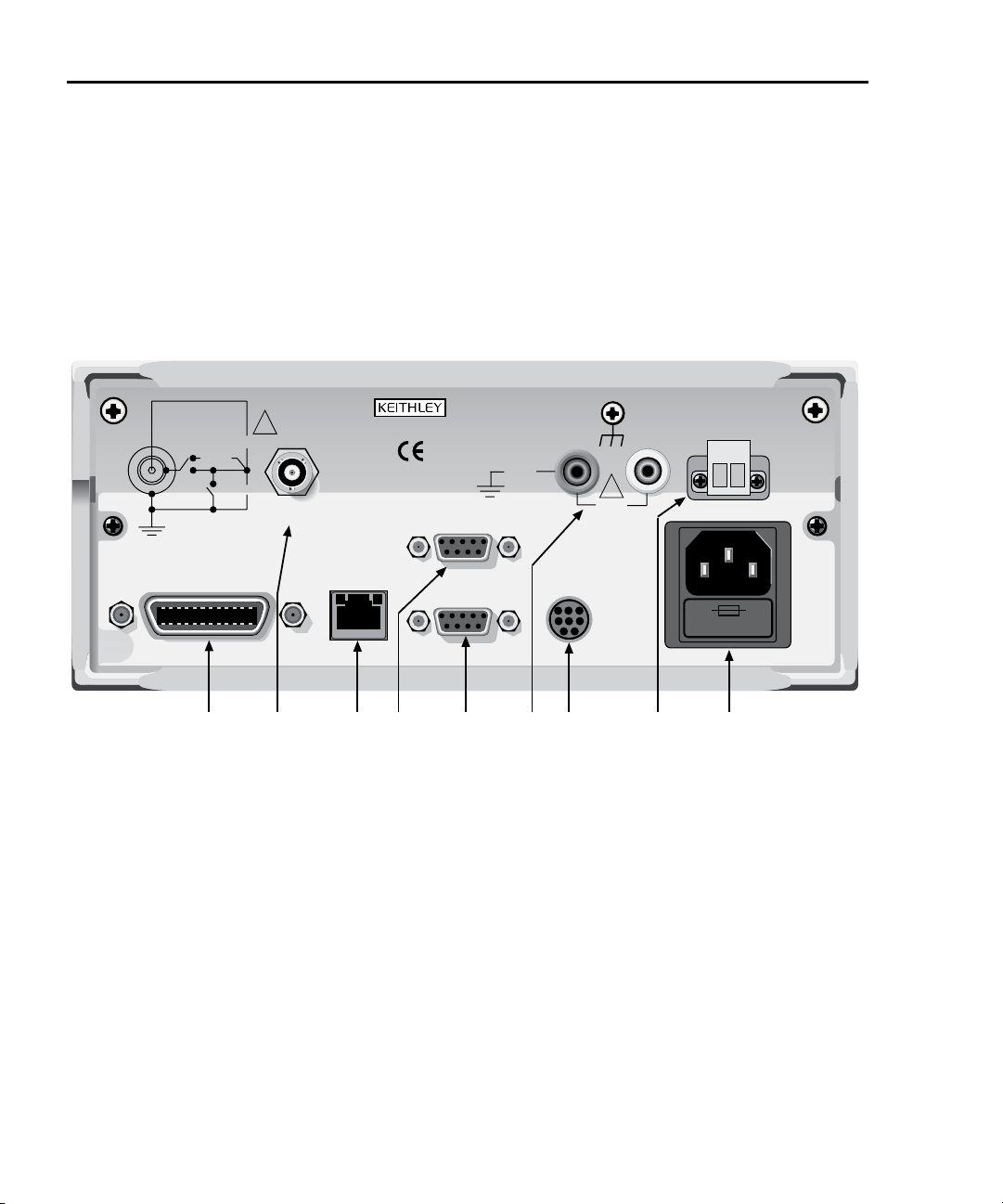
Figure 1-2
Model 622x rear panel
NOTE
The rear panels of the Model 6220 and 6221 are the same, except the
Model 6220 does not have an Ethernet connector (3).
105Vpk
105Vpk
250Vpk
HI
!
OUTPUT
CAT I
10bT 100bT
ETHERNET
10/100 BaseT
MADE IN
U.S.A.
DIGITAL I/O
RS-232
250Vpk
LO
TRIGGER
LINK
GUARD
!
105Vpk
LINE FUSE
SLOWBLOW
1.6A, 250V
LINE RATING
100-240VAC
50, 60Hz
120VA MAX.
INTERNALLY
SWITCHED
1 AMP MAX.
CABLE
GUARD
LO
IEEE-488
(CHANGE IEEE ADDRESS
WITH FRONT PANEL MENU)
1 234567 89
6221 only
1 IEEE-488
Connector for IEEE-488 (GPIB) operation. Use a shielded cable, such as the Model
7007-1 or 7007-2.
2 OUTPUT
3-lug female triax connector for current source output. Mates to the supplied triax cable
(237-ALG-2). Will also mate to any triax cable terminated with a 3-slot male triax connector.
INTERLOCK
3 ETHERNET
RJ45 female connector for Ethernet operation. Use an RJ45 male/male cable for connection. Two status LEDs are located at the top of the connector. These LEDs indicate status
of the Ethernet (see Section 10 of the Reference Manual for details).
Return to Section 1 topics
Page 23

Model 6220/6221 User’s Manual Getting Started 1-9
4 DIGITAL I/O
Male DB-9 connector. Four pins for digital output, one pin for Start of Test (SOT) trigger,
and one for external voltage (VEXT) input.
5 RS-232
Female DB-9 connector:
• For RS-232 operation, use a straight-through (not null modem) DB-9 shielded cable
for connection to the PC.
• For Delta, Pulse Delta, and Differential Conductance, use the supplied serial cable
(CA-351) for connections between the Model 622x and the Model 2182/2182A
.
6 LO and GUARD
Banana safety jacks for output low and banana jack Guard.
7 TRIGGER LINK
Eight-pin micro-DIN connector for sending and receiving trigger pulses among connected
instruments. Use a trigger link cable (Model 8501) for connections.
8 INTERLOCK
Interlock connector – Provides two screw terminals for connection to an interlock switch.
When the interlock switch is closed, the OUTPUT of the 622x is enabled, allowing it to be
turned on. When the interlock switch is opened, the OUTPUT is disabled (OUTPUT cannot be turned on and will turn off if it was on).
9 Power module
Contains the AC line receptacle and power line fuse. The instrument can operate on line
voltages of 100V to 240VAC at line frequencies of 50 or 60Hz.
Heat sink and cooling vents
The Model 622x uses a heat sink and three cooling vents to dissipate heat. The
right side of the case is cut out to expose the black, finned heat sink. Cooling
vents are provided on both sides of the case and on the top cover.
The heat sink could get hot enough to cause burns. Even if the instrument is
turned off, you should assume that the heat sink is still hot as it takes considerable
time for it to cool off.
Return to Section 1 topics
Page 24

1-10 Getting Started Model 6220/6221 User’s Manual
WARNING When handling the Model 622x, NEVER touch the heat sink
located on the right side of the case. This heat sink could be
hot enough to cause burns.
CAUTION NEVER place a container of liquid (e.g., water, coffee, etc.) on
the top cover. If it spills, the liquid will enter the case through
the vents and cause severe damage.
Excessive heat could damage the Model 622x and at the very least, degrade its
performance. The Model 622x must be operating in an environment where the
ambient temperature does not exceed 50°C.
CAUTION To prevent damaging heat build-up and thus ensure specified
performance, adhere to the following precautions:
• The heat sink must be kept free of dust, dirt, and contaminates, since its ability to dissipate heat could become
impaired.
• The cooling vents must be kept free of any obstructions.
DO NOT place any objects on the top cover. Even partial
blockage could impair proper cooling.
• DO NOT position any devices adjacent to the Model 622x
that force air (heated or unheated) into or onto its cooling
vents or surfaces. This additional airflow could compromise accuracy performance.
• For bench top use, the Model 622x can be placed on a hard
surface that is at ambient temperature. The feet of the
Model 622x will raise the chassis off the surface to allow
adequate ventilation under the unit. DO NOT use the Model
622x on a soft, compliant surface, like a carpet.
• The Model 622x can be set on top of another instrument
that is dissipating heat, but additional spacing is required.
In order to maintain full power capability, 1.75” of spacing
is required. The feet of the Model 622x only provide 0.625”
(5/8”) of spacing.
• Rack mounting requires 1U of vertical spacing at the top
and bottom of the Model 622x. 1U is a standard vertical
spacing unit and is equal to 1.75”. The typical distance
between the mounting screw holes on the rack rails is
0.125” (1/8”).
• When rack mounting the Model 622x, make sure there is
adequate airflow around the sides and top to ensure proper
cooling. Adequate airflow enables air temperatures within
approximately one inch of the Model 622x surfaces to
remain within specified limits under all operating conditions.
Return to Section 1 topics
Page 25

Model 6220/6221 User’s Manual Getting Started 1-11
• Rack mounting high power dissipation equipment adjacent
to the Model 622x could cause excessive heating to occur.
The specified ambient temperature must be maintained
around the surfaces of the Model 622x to specified accuracies.
• A good measure to ensure proper cooling in rack situations with convection cooling only is to place the hottest
equipment (e.g., power supply) at the top of the rack. Precision equipment, such as the Model 622x, should be placed
as low as possible in the rack where temperatures are
coolest. Adding space panels below the Model 622x will
help ensure adequate air flow.
Power-up
WARNING When handling the Model 622x, NEVER touch the heat sink
located on the right side of the case. This heat sink could be
hot enough to cause burns.
Line power connection
Follow the procedure below to connect the Model 622x to line power and turn on
the instrument. The current source operates from a line voltage of 100 to 240V at
a frequency of 50 or 60Hz. Line voltage and line frequency are automatically
sensed. There are no switches to set. Make sure the operating voltage in your
area is compatible.
CAUTION Operating the instrument on an incorrect line voltage may
cause damage to the instrument, possibly voiding the warranty.
1. Before plugging in the power cord, make sure that the front panel power
switch is in the off (O) position.
2. Connect the female end of the supplied power cord to the AC receptacle on
the rear panel. Connect the other end of the power cord to a grounded AC
outlet.
Return to Section 1 topics
Page 26

1-12 Getting Started Model 6220/6221 User’s Manual
WARNING The power cord supplied with the Model 622x contains a sepa-
rate ground wire for use with grounded outlets. When proper
connections are made, instrument chassis is connected to
power line ground through the ground wire in the power cord.
Failure to use a grounded outlet may result in personal injury
or death due to electric shock.
3. Turn on the instrument by pressing the front panel power switch to the on (I)
position.
Source preset
The PRES key can be used to set the source to a preset value. When the PRES
key is pressed, the source will set to the preset value (“PRES” message displayed). When the PRES key is pressed again, the unit will return to the original
source value. See “Source preset” on page 3-12 for details on setting the preset
value.
Disabling the front panel
The front panel (display and most controls) can be disabled to allow testing on
light sensitive devices; eliminate step-to-step timing jitter for Sweeps, Delta, and
Differential Conductance; and increase system speed.
The front panel can be disabled by pressing the DISP key. The following message
will be briefly displayed before the display shuts off:
FRONT PANEL DISABLED
Press LOCAL or DISP to resume.
As indicated in the displayed message, press LOCAL or DISP to enable the front
panel.
Remote programming – Use the following command to control the front panel:
DISPlay:ENABle <b> ‘
Enable or disable the front panel.
<b> = ON or OFF.
‘
Default setting is front panel ON.
‘
Step-to-step timing jitter
For Sweeps, Delta, and Differential Conductance, step-to-step timing may jitter as
much as 1ms. This jitter can be eliminated by disabling the front panel.
If the display is disabled while a Sweep, Delta, or Differential Conductance is running, a 2-second pause in continuous operation will occur. To avoid this pause,
disable the front panel before arming the Sweep, Delta or Differential Conductance test. Keep in mind that remote programming must then be used to arm and
start the test.
Return to Section 1 topics
Page 27
Model 6220/6221 User’s Manual Getting Started 1-13
Menus
Many aspects of operation are configured through menus. A direct access menu
can be opened by pressing a single key, and other menus require that the
CONGIF key be pressed before pressing another key.
CONFIG menus
NOTE “Press CONFIG > Press SWP” is an example of a key-
press sequence. To open the menu, press the CONFIG
key and then the SWP key.
Models 6220 and 6221:
CONFIG > SWP opens CONFIGURE SWEEPS menu (Section 4).
CONFIG > COND opens DIFF CONDUCTANCE menu (Section 5).
CONFIG > DELTA opens CONFIGURE DELTA menu (Section 5).
CONFIG > TRIG opens CONFIGURE TRIGGER menu (Section 8 of the
622x Reference Manual).
CONFIG > RECALL opens CLEAR BUFFER? menu (Section 6).
CONFIG > MATH opens CONFIGURE MATH menu (Section 6).
Model 6221 only:
CONFIG > PULSE opens CONFIG PULSE DELTA menu (Section 5).
CONFIG > WAVE opens CONFIGURE WAVEFORM menu (Section 7).
CONFIG > OUTPUT opens OUTPUT RESPONSE menu (Section 3).
Direct access menus
NOTE All of the following keys to open direct access menus (ex-
cept RECALL) can also be opened by first pressing the
CONFIG key.
Models 6220 and 6221:
COMM opens COMMUNICATIONS SETUP menu (page 1-17).
ADDR opens ADDRESS = (value) menu for GPIB.
UNITS opens READING UNITS menu (Section 3).
RECALL opens menu for stored readings and statistics (Section 6).
SAVE opens SAVED SETUP MENU (page 1-18).
SETUP opens RESTORE SETUP menu (page 1-18).
TRIAX opens CONFIGURE TRIAX menu (Section 2).
MENU opens MAIN MENU (see “MAIN menu” below).
Return to Section 1 topics
Page 28

1-14 Getting Started Model 6220/6221 User’s Manual
Model 6221:
AMPL opens menu to set AMPL: (value) (Section 7).
FREQ opens menu to set FREQ (frequency) (Section 7).
MAIN menu
The MAIN MENU is a direct access menu that is opened by pressing the MENU
key. Menu items include CAL, TEST, SERIAL#, and BEEPER. See Section 1 of
the Reference Manual for more information on these MAIN MENU items.
Editing controls
Source and compliance editing
When the Model 622x is in the edit mode (EDIT annunciator on), the editing controls are used to set source and compliance values. The typical way to enter the
edit mode is to press the EDIT key. Details on “Source and compliance editing”
are provided on page 3-8.
Menu navigation
When the Model 622x is not in the edit mode (EDIT annunciator off), the editing
controls (see Figure 1-3) are used to navigate menus to make selections and/or
set values.
Figure 1-3
Menu editing keys
6220 Editing Keys: 6221 Editing Keys:
Cursor Keys
Value Adjust Keys
RANGE
RANGE
Numeric Entry Keys
0 1 2 3 4 5 6 7 8 9 +/ 0000
ENTER / EXIT Keys
EXIT ENTER
Rotary Knob & Cursor Keys
PUSH TO ENTER
CURSOR
Cursor Keys
AMPL
FREQ
(right)(left)
Return to Section 1 topics
Value Adjust Keys
RANGE
RANGE
Numeric Entry Keys
0 1 2 3 4 5 6 7 8 9 +/ 0000
ENTER / EXIT Keys
EXIT ENTER
Page 29

Model 6220/6221 User’s Manual Getting Started 1-15
Model 6220 menu navigation
After entering a menu structure, use the editing keys as follows:
Selecting menu items
1. Use the Cursor Keys to place the blinking cursor on a menu item to be
opened or selected.
2. Press the ENTER key to select an item or open a sub menu.
3. Use the EXIT key to cancel a change or back out of the menu structure.
Setting a value
There are two ways to adjust a value: value adjust or numeric entry. Both methods
use the following editing techniques:
• To set a value to zero, press the 0000 numeric entry key.
• To toggle the polarity of a value, press the +/– numeric entry key.
Value adjust method:
1. Use the Cursor Keys to place the blinking cursor on the digit to be edited.
2. Use the Value Adjust Keys to increment or decrement the value of the digit.
Digit(s) to the left may also change as the edited value is changed beyond
“9” or under “0”.
3. Repeat steps 1 and 2 as needed to set the desired value.
4. Press ENTER to select the value. Pressing EXIT will cancel the change.
Numeric entry method:
1. Use the Cursor Keys to place the blinking cursor on the most significant
digit to be edited.
2. Key in a digit by pressing a Numeric Entry Key (0 to 9), The cursor moves
to the next digit on the right.
3. Repeat step 2 as needed to set the desired value.
4. Press ENTER to select the value. Pressing EXIT will cancel the change.
Return to Section 1 topics
Page 30

1-16 Getting Started Model 6220/6221 User’s Manual
Model 6221 menu navigation
Editing for the Model 6221 is basically the same as editing for the Model 6220,
except for the following differences:
• Cursor control is provided by the Cursor Keys located under the rotary
knob.
• When at a menu level that requires an item to be selected, the Rotary
Knob can also be used for cursor control. Turn the knob clockwise to move
the cursor to the right, and turn it counter-clockwise to move the cursor to
the left.
• With a value displayed, value adjust can be performed using the Rotary
Knob. Turn it clockwise to increment a digit, and turn it counter-clockwise to
decrement a digit.
• Pressing the ROTARY KNOB performs the same function as the ENTER
key. Press the knob to select or open a menu item, or to select a displayed
value.
Password
For remote programming, a user-defined password can be used to disable protected commands. Most Model 622x commands are protected. From the front
panel, the password can be cleared using the following key-press sequence:
Press COMM > Select PASSWORD > Select YES to clear the password
See Section 10 of the Reference Manual for details on password.
Return to Section 1 topics
Page 31
Model 6220/6221 User’s Manual Getting Started 1-17
Remote interface
For remote operation, one of the following interfaces can be used: GPIB, RS-232,
and (for the Model 6221) Ethernet. When using the GPIB, the SCPI or KI-220 lanuage can be used.
NOTE Interface selection and configuration can be performed
from the COMMUNICATIONS SETUP menu, which is accessed by pressing the COMM key. All details on interface selection and configuration are provided in Section
10 of the Reference Manual.
GPIB
At the factory, the GPIB (SCPI language) is the selected interface and the GPIB
address is set to 12. Use the following key-press sequence to change the
address:
Press ADDR > Set the address (0 to 30) > Press ENTER
RS-232
When the RS-232 interface is selected, the following defaults are intially set (but
can be changed):
Baud rate: 19.2k
Terminator: LF (line feed)
Flow control: None
Eight data bits, one stop bit, and no parity are used for the RS-232. These settings
are fixed and cannot be changed.
Ethernet (Model 6221 only)
The information for setting up the Ethernet is provided in Section 10 of the Reference Manual (see “Ethernet interface reference”).
Error and status messages
Error and status messages are displayed momentarily. During operation and programming, you will encounter a number of front panel messages. Typical messages are either status or error type, as listed in Appendix B of the Reference
Manual.
Return to Section 1 topics
Page 32

1-18 Getting Started Model 6220/6221 User’s Manual
Default settings
The Model 622x can be restored to one of seven setup configurations: five usersaved setups, PRESET (bench defaults), and *RST (bus defaults). As shipped
from the factory, the Model 622x powers up to the PRESET settings. PRESET settings provide a general purpose setup for front panel operation, while the *RST
settings do the same for remote operation.
NOTE User setups cannot be saved or recalled while Wave,
Sweep, Delta, Pulse Delta, or Differential Conductance is
armed or running. Attempting to do so will generate error
+413 Not allowed with mode armed.
A custom sweep cannot be saved as a user setup. Attempting to do so will generate error +528 Cannot save
CUSTOM sweep setup.
Source preset values are not saved as part of a user setup.
See Section 1 of the Reference Manual for more information on “Default settings”
including a table that lists all the default settings.
Save and restore setups
Save setup:
Press SAVE > Select SAVE > Set memory location (0 to 4) > Press ENTER
Restore user setup:
Press SETUP > Select USER > Set memory location (0 to 4) > Press ENTER
Restore PRESET defaults:
Press SETUP > Select PRESET
Restore *RST defaults:
Press SETUP > Select *RST
Remote programming
*SAV <NRf> ‘ Save present setup in memory.
*RCL <NRf> ‘‘Recall saved user setup from memory.
SYSTem:PRESet ‘ Restore PRESET default setup.
*RST ‘ Restore *RST default setup.
Return to Section 1 topics
<NRf> = 0, 1, 2, 3, or 4
Page 33

Model 6220/6221 User’s Manual Getting Started 1-19
Select power-on setup
Power-on to PRESET defaults:
Press SETUP > Select POWER ON > Select PRESET
Power-on to *RST defaults:
Press SETUP > Select POWER ON > Select *RST
Power-on to user setup:
Press SETUP > Select POWER ON > Select USER SETUP NUMBER >
Set memory location (0 to 4) > Press ENTER
Remote programming
SYSTem:POSetup <name> ‘
SCPI programming
SCPI programming information is integrated with front panel operation throughout
this manual. SCPI commands are listed in tables and additional information that
pertains exclusively to remote operation is provided after each table.
NOTE Except for Section 14 in the Reference Manual, most
SCPI tables in this manual are abridged to some degree.
That is, they may NOT include optional command words
and most query commands. Optional command words
and query commands are summarized as follows.
Optional command words
In order to be in conformance with the IEEE-488.2 and SCPI standards, the
Model 622x accepts optional command words. Any command word that is enclosed
in brackets ([]) is optional and need not be included in the program message.
Select power-on setup.
‘
<name> = RST, PRESet, SAV0, SAV1, SAV2, SAV3, or
‘
SAV4.
Query commands
Most command words have a query form. A query command is identified by the
question mark (?) that follows the command word. A query command requests
(queries) the programmed status of that command. When a query command is
sent and the Model 622x is addressed to talk, the response message is sent to
the computer.
Return to Section 1 topics
Page 34

1-20 Getting Started Model 6220/6221 User’s Manual
Return to Section 1 topics
Page 35

Section 2 topics
2
Output Connections
Output connectors, page 2-2
Triax connector, page 2-2
Ground points, page 2-3
LO and GUARD banana jacks, page 2-3
INTERLOCK, page 2-4
Output configurations, page 2-5
Triax inner shield, page 2-6
Triax output low, page 2-7
Guards, page 2-8
Triax Cable Guard, page 2-8
Floating the current source, page 2-9
Connections to DUT, page 2-9
Supplied triax cable, page 2-9
Basic connections, page 2-10
Shields and guarding, page 2-10
Using a test fixture, page 2-12
NOTE The information in this section is an abbreviated version of
the information in Section 2 of the Reference Manual. Refer to
Section 2 of the Reference Manual for complete details and
additional information that is not provided in this manual.
Page 36

2-2 Output Connections Model 6220/6221 User’s Manual
Output connectors
Triax connector
Current source output is accessed at the 3-lug female triax connector on the rear
panel. Use a 3-slot male triax cable to make connections to this connector. A triax
cable terminated with alligator clips (Model 237-ALG-2) is a supplied item for the
Model 622x (see “Supplied triax cable” on page 2-9). The triax connector is shown
in Figure 2-1.
Figure 2-1
Triax connector and grounds points
622x
Earth
Ground
Earth
Ground
Chassis
OUTPUT
1
FVR
Chassis
EARTH GROUND is a local signal ground and is defined as
the outer shield (shell) of the triax connector.
CHASSIS is defined as the metal chassis of the Model 622x.
Chassis screw terminal is connected to the metal chassis of the
Model 622x.
Chassis
Screw
Center conductor Output High
Inner shield Output Low or Cable Guard
Outer shield
(Earth Ground)
1) Frequency Variable Resistor (FVR) Isolates
the current source from high frequencies on
2
the chassis. For DC to 60Hz, the FVR is a
virtual short (zero ohms).
2) DO NOT use the Chassis Screw terminal to
make signal connections to external circuitry.
High frequency (>1MHz) on the chassis may
result in higher noise at the output.
Output Low for guarded configuration.
Triax connector terminals
The triax connector terminals are summarized as follows. For details on these terminals, see “Output configurations” on page 2-5.
Center conductor – The center conductor of the triax connector is always connected to Output High of the current source.
Inner shield – The inner shield of the triax connector can be connected to Output
Low or Cable Guard. See “Triax inner shield” on page 2-6 for details on the inner
Return to Section 2 topics
Page 37

Model 6220/6221 User’s Manual Output Connections 2-3
shield connection setting. See “Triax Cable Guard” on page 2-8 for details on
using the Cable Guard.
Outer shield – The outer shield of the triax connector is always connected to
Earth Ground of the Model 622x (see “Ground points” for details).
Frequency variable resistor (FVR)
The outer shield (Earth Ground) of the triax connector is isolated from the chassis
of the Model 622x by a Frequency Variable Resistor (FVR). The FVR (shown in
Figure 2-1) is used to isolate the current source circuitry from high frequencies
that may be present on the chassis of the Model 622x. As frequencies on the
chassis increase, the resistance of the FVR increases to dampen its effects.
Ground points
The various ground points used by the Model 622x are shown and explained in
Figure 2-1. The ground point for signal connections to external circuitry is Earth
Ground. Earth Ground is the outer shield of the triax connector and is isolated
from the Chassis by the FVR.
Keep in mind that the Chassis should never be used as a ground point for signal
connections. High frequencies present on the chassis of the Model 622x may
result in higher noise on the output.
The Chassis should only be used as a safety shield. Use the Chassis Screw for
connections to the chassis of the Model 622x.
LO and GUARD banana jacks
The LO and GUARD banana jacks are located on the rear panel and are shown in
Figure 2-2.
Figure 2-2
LO and GUARD banana jacks
GUARDLO
105Vpk
LO banana jack
The LO banana jack is electrically identical to the Output Low accessed at the
triax connector. However, when using the CABLE GUARD and FLOATING triax
settings, Output Low is not available at the triax connector. The LO banana jack
must be used as Output Low (see “Output configurations” on page 2-5 for details
on the triax connector settings).
Return to Section 2 topics
Page 38

2-4 Output Connections Model 6220/6221 User’s Manual
GUARD banana jack
The GUARD available at the banana jack is different from CABLE GUARD that
can be accessed at the triax cable. See “Guards” on page 2-8 for more information.
INTERLOCK
The Model 622x is equipped with an INTERLOCK that is to be connected to an
interlock switch (see Figure 2-3). When the interlock switch is open, the OUTPUT
of the Model 622x is disabled and cannot be turned on. If the OUTPUT is already
on, opening the interlock switch will turn the OUTPUT off. When the interlock
switch is closed, the OUTPUT is enabled and can be turned on.
Figure 2-3 shows the connector for INTERLOCK. It is a quick-disconnect
screw-terminal block. Pull the terminal block off the rear panel to connect the interlock switch.
The interlock switch is mounted on a test fixture such that the switch will open
(disable the OUTPUT) when the test fixture lid is opened. The switch will close
(enable the OUTPUT) when the test fixture lid is closed. See “Using a test fixture”
page 2-12 for details on using INTERLOCK with a test fixture.
Figure 2-3
INTERLOCK
INTERLOCK
Test Fixture
Normally
Open
Switch
NOTE The maximum allowable interlock
circuit impedance is 10W.
OUTPUT disabled
with switch open
WARNING An open INTERLOCK only disables the output from the Model
622x. If an external source is being used in the test circuit, its
voltage will be present in the test circuit. A hazardous voltage
from an external source could be connected directly to the
OUTPUT connector of the Model 622x.
As a general rule of safety, always turn off all external sources
before making or breaking connections to the test circuit.
Return to Section 2 topics
Page 39

Model 6220/6221 User’s Manual Output Connections 2-5
Output configurations
There are four configurations that can be used for current source output:
• Triax inner shield is connected to Output Low, which is connected to Earth
Ground (see Figure 2-4A).
• Triax inner shield is connected to Cable Guard and Output Low is connected to Earth Ground (see Figure 2-5A).
• Triax inner shield is connected to Output Low, which is disconnected from
Earth Ground (Floating) (see Figure 2-4B). This is the default setting.
• Triax inner shield is connected to Cable Guard. Output Low is accessed at
the LO banana jack and is disconnected from Earth Ground (Floating) (see
Figure 2-5B).
Using the Model 622x with the triax inner shield connected to Output Low makes it
compatible with the Keithley Model 220 current source.
WARNING To prevent electric shock and/or damage to the Model 622x, DO
NOT exceed the maximum (Max) voltage levels indicated in
Figure 2-4 and Figure 2-5.
CAUTION To prevent damage to internal fuses of the Model 622x, current
from output low to earth ground must be limited to 1A. Use a
fuse or other current limiting device in the external test circuit.
One internal fuse is located between the Triax Output Low and
banana jack LO. The other internal fuse is located between
Triax Output Low and earth ground.
Figure 2-4
Output configurations – triax inner shield connected to Output Low
A) Triax Output Low setting: Earth Ground B) Triax Output Low setting: Floating
622x
Earth
Ground
OUTPUT
Chassis
FVR
2
105V
Max
Output High
Output Low
Earth Ground
1) Boot color for alligator
2) Frequency Variable
1
(red)
1
(black)
1
(green)
clip if using supplied
triax cable.
Resistor (FVR). See
Figure 2-1.
622x
Earth
Ground
OUTPUT
Chassis
FVR
2
105V
Max
250V
Max
Output High
Output Low
Earth Ground
Return to Section 2 topics
(red)
(black)
(green)
1
1
1
Page 40

2-6 Output Connections Model 6220/6221 User’s Manual
Figure 2-5
Output configurations – triax inner shield connected to Cable Guard
A) Triax Output Low setting: Earth Ground B) Triax Output Low setting: Floating
62xx
OUTPUT
Earth
Ground
FVR
Chassis
Triax inner shield
The inner shield of the triax connector can be connected to Output Low (to be
compatible with the Keithley 220 Current Source) or to Cable Guard. Output Low
is the default connection.
The current source OUTPUT must be OFF in order to change the inner shield setting. Perform the following steps to check or change the inner shield connection:
62xx
105Vpk
Max
105Vpk
Max
Output High
Cable Guard
(red)
(black)
1
1
OUTPUT
LO
105Vpk
Max
105Vpk
Output Low
2
(Earth Ground)
1) Boot color for alligator
clip if using supplied
triax cable.
2) Frequency Variable
Resistor (FVR). See
Figure 2-1.
(green)
1
Earth
Ground
FVR
2
Chassis
250Vpk
Max
1. If the current source output is on, press the OUTPUT key to turn it OFF
(“OFF” message is displayed).
2. On the Model 622x, press the TRIAX key to display the CONFIGURE
TRIAX menu.
3. Using the cursor controls, place the blinking cursor on INNER SHIELD and
press the ENTER key to display the TRIAX INNER SHIELD options.
4. Place the cursor on OUTPUT LOW (220 STYLE) or GUARD and press the
ENTER key.
5. Press the EXIT key to return to the normal display state.
Max
Output High
Cable Guard
(red)
(black)
1
1
Output Low
Earth Ground
(green)
1
Remote programming (triax inner shield)
Changing the inner shield connection can only be done with the current source
OUTPUT OFF. Otherwise, error +403 Not allowed with output on will occur.
Return to Section 2 topics
Page 41

Model 6220/6221 User’s Manual Output Connections 2-7
Commands for triax inner shield connection:
OUTPut:ISHield? ‘ Query connection for triax inner shield.
OUTPut:ISHield <name> ‘‘Connect inner shield to Cable Guard or Output Low.
<name> = GUARd or OLOW
Example – Turns off the current source OUTPUT and connects the inner shield of
the OUTPUT connector to Cable Guard:
OUTPut OFF
OUTPut:ISHield GUARd
Triax output low
Output Low can be connected to Earth Ground (which is the outer shell of the triax
connector) or it can float. By default, Output Low floats.
Perform the following steps to check or change the Output Low connection:
1. On the Model 622x, press the TRIAX key to display the CONFIGURE
TRIAX menu.
2. Using the cursor controls, place the blinking cursor on OUTPUT LOW and
press the ENTER key to display the TRIAX OUTPUT LOW options.
3. Place the cursor on FLOATING or EARTH GROUND and press the ENTER
key.
4. Press the EXIT key to return to the normal display state.
Remote programming (triax output low)
Commands for output low connection:
OUTPut:LTEarth? ‘ Query connection for output low.
OUTPut:LTEarth <b> ‘
Example – Disconnects (floats) triax output low from Earth Ground:
OUTPut:LTEarth OFF
Return to Section 2 topics
Enable or disable triax output low connection to Earth
Ground.
‘
<b> = ON (Earth Ground)
‘
= OFF (Floating)
‘
Page 42
2-8 Output Connections Model 6220/6221 User’s Manual
Guards
The Model 622x provides two guards: triax Cable Guard and banana jack Guard.
Cable Guard – This guard provides a voltage that is at essentially the same
potential as Output High of the Model 622x. Guarding may greatly reduce leakage
current and capacitance in the test circuit. Effective guarding requires that the
triax Cable Guard configuration be used for the triax cable and a guard plate be
used for the DUT.
Banana Jack Guard – This guard is similar to cable guard in that it provides a
voltage that is essentially the same potential as Output High (1mV accuracy, typical). This guard should not be used to guard a triax cable. Rather, banana jack
Guard is designed for use with a voltmeter to make measurements on a highimpedance DUT.
NOTE Details on using the banana jack Guard is provided in
Section 2 of the Reference Manual.
Triax Cable Guard
A triax cable has insulation resistance and capacitance between its conductors. A
typical triax cable could typically have 1TΩ/ft. of insulation resistance and 100pF/ft.
of cable capacitance. Significant insulation resistance and capacitance can also be
present in the test fixture for the DUT.
Capacitance – Any capacitance that exists between the output and the DUT
slows down the response (current rise time) at the DUT. When the Model 622x
output is turned on (or a step change occurs), there is an initial current surge
through the capacitance seen across the load. Current will stop flowing through
the capacitor after it fully charges. A current is considered to be “settled” when it is
within 1% of its final value. It takes approximately five RC time constants (5
the capacitor to charge and allow the settled current to flow through the DUT.
Leakage current – After the capacitance charges, it is effectively removed from
the test circuit (assuming the source level remains constant). Insulation resistance
in parallel with the DUT is left, effectively making a current divider. Leakage current (not delivered to the DUT) can be significant if the insulation resistance is not
significanly greater than the resistance of the DUT. For example, if the insulation
resistance is only 10 times the resistance of the DUT, then 10% sourcing error will
occur.
NOTE The principles of guarding are explained in Section 2 of
the Reference Manual (see “Guards”).
τ) for
Return to Section 2 topics
Page 43

Model 6220/6221 User’s Manual Output Connections 2-9
When to use Cable Guard
When to use Cable Guard is a judgement call that must be made by the user. In
general, Cable Guard is used to reduce leakage current for high-impedance DUT,
and reduce capacitance in the triax cable and at the DUT to improve output
response (rise time). Lower capacitance results in faster output response.
While Cable Guard will greatly reduce capacitance in the triax cable and at the
DUT, there are other possible sources of high capacitance that can greatly
degrade the overall effectiveness of guarding.
The DUT (or test circuit) may inherently have high capacitance, and/or the voltmeter
used in the test system may have high capacitance. These capacitances, which
cannot be guarded out, may negate the need for Cable Guard (especially for lowimpedance DUT). The Keithley Model 2182/2182A Nanovoltmeter has relatively
high input capacitance (~300pF, and ~500pF in special mode only).
Floating the current source
Using an external source in the test system may require that the Model 622x
current source float off Earth Ground. Depending on the test circuit configuration,
the external source could possibly be shorted through Earth Ground if the Model
622x is not floating off Earth Ground. Details on “Floating the current source” are
provided in Section 2 of the Reference Manual.
Connections to DUT
WARNING To prevent electric shock, all power must be removed from the
test system before making or breaking connections. Turn off all
equipment and sources, and disconnect their power cords.
Supplied triax cable
The Model 237-ALG-2 triax cable is supplied with the Model 622x. This 6.6ft (2m)
cable mates to the OUTPUT triax connector and is terminated with alligator clips
that are covered with color-coded boots. Terminal identification for the cable
depends on the triax connector configuration (see Figure 2-4 and Figure 2-5).
WARNING The Model 237-ALG-2 triax cable can allow exposed voltages
when used in certain applications.
This triax cable is intended for use only by qualified personnel
who recognize shock hazards and are familiar with the safety
precautions required to avoid possible injury. If this product is
to be used by an operator, a qualified person must ensure the
operator is protected from electric shock and contact with hazardous live circuits.
Return to Section 2 topics
Page 44

2-10 Output Connections Model 6220/6221 User’s Manual
Basic connections
Basic connections can be used for low voltage (not greater than 30Vrms,
42Vpeak) testing where guarding and/or noise shielding are not required. Basic
connections to a DUT are shown in Figure 2-6. Use the connections shown in
Figure 2-6A if the inner shield of the triax connector is connected to Output Low.
Use the connections shown in Figure 2-6B if the inner shield is connected to
Cable Guard.
Figure 2-6
Basic connections to DUT
A) Inner shield connected to Output Low
High
(red*)
622x
B) Inner shield connected to Cable Guard
High
(red*)
622x
DUT
Output
Low
(black*)
* Boot color for alligator clip if
using supplied triax cable.
Output
Low
(Earth Ground)
(green*)
Shields and guarding
Noise shield connections
Figure 2-7 shows typical noise shielding for the two triax connector configurations.
A noise shield is used to prevent unwanted signals from being induced into the
test circuit. A test current below 1μA may benefit from effective shielding. Typically,
the metal noise shield surrounds the DUT and is connected to Output Low.
Figure 2-7
Noise shield
A) Inner shield connected to Output Low B) Inner shield connected to Cable Guard,
Metal Noise Shield
High
(red*)
622x
DUT
Output
Output Low connected to earth ground
Metal Noise Shield
High
(red*)
622x
DUT
Output
DUT
Low
(black*)
* Boot color for alligator clip if
using supplied triax cable.
Return to Section 2 topics
Low
(Earth Ground)
(green*)
Page 45

Model 6220/6221 User’s Manual Output Connections 2-11
Safety shield connections
A safety shield must be used whenever hazardous voltages (>30Vrms, 42Vpeak)
will be present. The metal safety shield must completely surround DUT test circuitry and must be connected to a known Safety Earth Ground and Chassis (see
Figure 2-8). Use #18AWG wire or larger for connections.
Figure 2-8
Safety shield
A) Inner shield connected to Output Low B) Inner shield connected to Cable Guard,
High
622x
Output
Low
(black*)
(red*)
DUT
Earth Ground
(green*)
* Boot color for alligator clip if
using supplied triax cable.
Metal
Safety
Shield
Safety
Earth
Ground
Output Low connected to earth ground
High
(red*)
622x
DUT
Output
Low
(Earth Ground)
(green*)
Chassis
Screw
Metal
Safety
Shield
Safety
Earth
Ground
Cable Guard connections
Triax Cable Guard is used to provide guarding for the triax cable and can be
extended all the way to the DUT at a metal guard plate. Connections for Cable
Guard are shown in Figure 2-9.
Figure 2-9
Cable Guard connections – triax inner shield connected to Cable Guard
Triax Cable
High
(red*)
622x
Guard
Plate
Output
Output Low connected
to earth ground
Cable Guard
(black*)
Low
(Earth Ground)
(green*)
* Boot color for alligator clip if
Return to Section 2 topics
DUT
using supplied triax cable.
Page 46

2-12 Output Connections Model 6220/6221 User’s Manual
A safety shield must be used whenever hazardous voltages (>30Vrms, 42Vpeak)
will be present in the test circuit. Figure 2-10 shows how to make guarded connections with the use of a safety shield.
Using shielding and guarding together
Figure 2-10 shows connections for a test system that uses a noise shield, a safety
shield, and guarding.
Figure 2-10
Connections for noise shield, safety shield, and guarding
Triax Cable
622x
Output
High
(red*)
Cable Guard
(black*)
Metal Noise Shield
DUT
Metal
Safety
Shield
Guard
Plate
(Earth Ground)
Chassis
Screw
Triax inner shield connected to Cable Guard
Output Low connected to earth ground
Using a test fixture
In order to faciliate safe operation and optimum performance, a safety test fixture
with a built-in interlock switch must be used. The interlock switch of the test fixture
is to be connected to the “INTERLOCK” of the Model 622x (see page 2-4).
NOTE Guidelines to build a safe, high performance test fixture
are provided in Section 2 of the Reference Manual (see
“Using a test fixture”).
Low
(green*)
Safety
Earth
Ground
* Boot color for alligator clip if
using supplied triax cable.
Return to Section 2 topics
Page 47
DC Current Source Operation
Section 3 topics
Current source output capabilities, page 3-2
Source ranges, page 3-2
Compliance, page 3-3
Output power (source or sink), page 3-3
Output response, page 3-5
Setting source and compliance, page 3-8
Source and compliance editing, page 3-8
Sourcing current, page 3-12
Remote programming – source output commands, page 3-15
NOTE The information in this section is an abbreviated version of
the information in Section 3 of the Reference Manual. Refer
to Section 3 of the Reference Manual for complete details and
additional information that is not provided in this manual.
3
NOTE Supplied example software allows you to control a Model
622x from any PC using simple mouse clicks through a virtual
front panel. For details, see “Using the example software” in
Section 10 of the Reference Manual.
Page 48

3-2 DC Current Source Operation Model 6220/6221 User’s Manual
Current source output capabilities
• Nine ranges to source current from 100fA to 105mA.
• Compliance can be set from 0.1V to 105V in 10mV steps.
• Maximum output power is 11W.
• Four quadrant (source and sink) source operation
Source ranges
Each source range has 5% overrange capability. Each source range and its maximum output is listed in Table 3-1. A source range can be selected manually, or
autorange can be used.
Manual ranging – A fixed source range can be selected manually using the
RANGE and
sible range that will accommodate the output current. For example, if sourcing
12mA, select the 20mA range.
Autorange – For front panel operation, the AUTO key is a single action control.
When pressed, the best range is selected for the displayed source value. For remote
operation, autorange is always active when it is enabled, and the Model 622x will
automatically select the best (lowest) source range for the source value.
keys. When selecting a fixed range, select the lowest (best) pos-
NOTE More information on “Autorange” is provided on
page 3-11. The commands for ranging are listed in Table
3-2.
Tab le 3- 1
Source ranges and maximum outputs
Source
Range
2nA ±2.1nA 2µA ±2.1µA 2mA ±2.1mA
20nA ±21nA
200nA ±210nA
Max
Output
Source
Range
20µA ±21.µA 20mA ±21mA
200µA ±210µA 100mA ±105mA
Return to Section 3 topics
Max
Output
Source
Range
Max
Output
Page 49

Model 6220/6221 User’s Manual DC Current Source Operation 3-3
Compliance
The compliance setting limits the output voltage of the Model 622x. The voltage
compliance limit can be set from 0.1V to 105V in 10mV steps. The output will not
exceed the programmed compliance level.
Make sure to set compliance to a voltage level that is greater than the voltage
requirements for the load. For example, if sourcing 10mA to a 1kΩ load, the voltage compliance setting must be >10V (10mA x 1kΩ = 10V). If it is not, the Model
622x goes into compliance and the magnitude of the current output will be less
than the programmed setting. For example, if compliance is set to 9V and current
output is set to 10mA, only 9mA will be sourced to a 1kΩ load (9V/1kΩ = 9mA).
The OUTPUT indicator light blinks when the current source is in compliance.
Either there is a fault condition in the test circuit, or the source and/or compliance
levels are not properly set.
Compliance overshoot
Depending on range and load impedance, step changes in current could cause
the output voltage to briefly overshoot its normal expected level by as much as 2V.
During normal “out of compliance” operation, this voltage “glitch” will settle to the
expected output voltage within the settling time specification for the selected
range (see “Output response” on page 3-5).
If the compliance voltage is set too close to the expected output voltage, the overshoot could place the Model 622x in compliance. Due to the compliance circuitry,
it could take several microseconds for the overshoot to settle and return the current source to the “out of compliance” state. This slower response to overshoot
could damage a voltage sensitive DUT (Device Under Test).
One way to avoid compliance overshoot is to set a compliance that is at least 2V
above the expected static output voltage. For example, if the normal operating
voltage across the load is 10V, set the compliance to at least 12V.
Additional details on compliance overshoot and prevention are provided in
Appendix E of the Reference Manual.
Output power (source or sink)
The maximum power output of the Model 622x is 11W. The bipolar current source
provides four quadrant source or sink operation. When connected to a passive
DUT, the Model 622x operates as a source. When connected to an active load
(e.g., external source, capacitor), the Model 622x can operate as a source or sink.
When operating as a source, current is delivered to a test circuit. The polarity of
the current and the voltage seen at the output are the same (both positive or both
negative).
Return to Section 3 topics
Page 50

3-4 DC Current Source Operation Model 6220/6221 User’s Manual
When operating as a sink, the Model 622x is dissipating power rather than sourcing it. The polarity of the current and voltage seen at the output is opposite (one
positive, one negative). An external source or an energy storage device, such as a
capacitor, can force operation into the sink region.
Figure 3-1shows examples of the Model 622x connected to an external source
where it can operate as a source or sink. For both examples, the Model 622x is
programmed to output +10mA. When connected to the 1kΩ resistor and 10V
source as shown in Figure 3-1A, the Model 622x operates as a 200mW source
supplying power to the external test circuit. When the external voltage is
decreased to -30V as shown in Figure 3-1B, the Model 622x instead operates as
a sink. The Model 622x dissipates 200mW of power (10mA x -20V = -200mW).
Figure 3-1
Source and sink examples
A) Source operation
10mA
1kW
B) Sink operation
10mA
1kW
10V
-30V
622x
+10mA
10V
Hi
20V
Lo
10V
+10mA
622x
Hi
-20V
Lo
Operating boundaries
Figure 3-2 shows the four quadrants of operation for the Model 622x. When oper-
ating in the first (I) or third (III) quadrant, the Model 622x is operating as a source.
Figure 3-1A shows an example of quadrant I operation (current and voltage both
positive).
When operating in the second (II) or fourth (IV) quadrant, the Model 622x is operating as a sink. Figure 3-1B shows an example of quadrant IV operation (current
positive and voltage negative).
Return to Section 3 topics
Page 51

Model 6220/6221 User’s Manual DC Current Source Operation 3-5
Figure 3-2
Output boundaries (source and sink)
+I
105mA
Quadrant IV
Sink
-V
-105V
Quadrant III
Source
Output response
Output response is the time it takes for an output change to settle to within 1% of
its final value. For the Model 6220, output response (settling time) can be as fast
as 100µs (typical). For The Model 6221, output response can be as fast as 2µs
(typical) for the higher source ranges. If desired, the output response of the Model
6221 can be set to match the output response of the Model 6220 (both typically
100µs).
For the Models 6220 and 6221, an analog filter can be enabled to slow down the
output response. For a high-impedance load, the analog filter reduces overshoot,
excessive noise, and instability (oscillation).
Quadrant I
Source
+V
105V
Quadrant II
Sink
-105mA
-I
Analog filter
The Model 622x has an analog filter that, when enabled, will slow down the output
response (settling time) of the current source.
When the analog filter is enabled, a capacitor (typically 33pF) is placed across the
output. Depending on the load impedance, the analog filter may or may not significantly increase the settling time of the current source.
Return to Section 3 topics
Page 52

3-6 DC Current Source Operation Model 6220/6221 User’s Manual
For example, assume the Model 6221 is on the 2mA range and FAST response is
selected. For this configuration, the Settling Time is specified at 2µs (typical). Also
assume the load impedance is 1kΩ. With the analog filter enabled, the additional
settling time (five time constants) is calculated as follows:
Additional settling time = 5RC
=5 x 1kΩ x 33pF
= 0.165µs
Enabling the analog filter adds 0.165µs settling time, which is not a significant
increase in comparison to 2µs.
Now assume the load is 1MΩ. The additional settling time with the analog filter
enabled is 165µs (5 x 1MΩ x 33pF). The analog filter greatly increased the settling
time from 2µs to approximately 167µs.
NOTE The above example is only intended to show how load
impedance affects settling time when using the analog
filter. Actual settling times will also depend on other impedances present in the test circuit, such as capacitance
and leakage resistance in cabling and in the test fixture.
For load impedances <10kΩ, the analog filter has little effect on the output
response. At the 10kΩ load impedance point, the filter capacitor across the load
creates a filter response of less than 1MHz, which is the maximum output bandwidth of the Model 6221 for the higher current ranges.
For load impedances greater than 1MΩ, the reduced response of the filtered
output can significantly reduce overshoot, noise, and instability (oscillation).
With the analog filter disabled, the output capacitance of the Model 622x is <10pF.
If not sure about using the analog filter, experimentation may be the best way to
determine which analog filter state (enabled or disabled) provides the best results.
NOTE An external user-supplied filter can be effective at reduc-
ing high frequency noise generated by the Model 622x
current source. For details, see “External user-supplied
filter” in Appendix E of the Reference Manual.
Return to Section 3 topics
Page 53

Model 6220/6221 User’s Manual DC Current Source Operation 3-7
Response speed setting (6221 only)
The filter response speed of the Model 6221 can be set for FAST or SLOW. For
the SLOW setting, the output response of the Model 6221 is the same as the output response of the Model 6220.
The FAST setting allows a faster output response. The FAST response setting
changes the maximum output response bandwidth of the Model 6221 to 1MHz. It
also reduces stability. The output will remain stable into a 10µHz (typical) load. For
a more complex load, the faster speed may make the test system more susceptible to oscillation.
Note that output stability into an inductive load is only dependent on the response
mode setting and is not affected by the analog filter (on or off).
Again, experimentation may be the best way to determine which response setting
(FAST or SLOW) provides the best results.
Settling time specifications
The output “Settling Time” specifications are listed in Appendix A and assume that
the analog filter is disabled. For the Model 6221, settling times are provided for the
FAST and SLOW response speed settings. Note that the SLOW setting of the
Model 6221 has the same response as the Model 6220. Enabling the analog filter
may or may not significantly increase settling times. For details, see “Analog filter”
on page 3-5.
NOTE All settling times are typical into a resistive load to 1% of
final value.
The listed settling times in Appendix A are specified for a resistive load. The max-
imum load resistance for the specified settling times is calculated as follows:
Max Load Resistance = 2V / I
For example, on the 20mA range, the max load resistance is calculated as follows:
Max Load Resistance = 2V / 20mA = 100Ω
The settling times for other load conditions can be calculated as explained in
Section 3 of the Reference Manual (see “Settling time specifications”).
Return to Section 3 topics
FULL SCALE OF RANGE
Page 54

3-8 DC Current Source Operation Model 6220/6221 User’s Manual
Setting source and compliance
Source and compliance editing from the front panel cannot be performed from the
front panel if the Model 622x is in remote. To return to the local state, press the
LOCAL key.
For remote programming, commands to select source range, and set source
and compliance values are shown in Table 3-2. Programming examples are also
provided in the procedure for “Sourcing current” on page 3-12.
Source and compliance editing
Figure 3-3 explains how to set source and compliance values for the Model 6220.
Figure 3-4 shows the source and compliance editing controls for the Model 6221.
The procedure to set source and compliance values for the Model 6221 follow
Figure 3-4. “Source/compliance editing notes” for both procedures are provided
on page 3-9.
Figure 3-3
Source and compliance editing – Model 6220
Step 1
Select DC
output mode
DC
Step 4 Set source or compliance value
Value Adjust Keys
Cursor Keys
Step 2 Select source range
1
RANGE
AUTO
RANGE
Numeric Entry Keys
0 1 2 3 4 5 6 7 8 9 +/ 0000
While in the edit mode, use the Value
Adjust Method or Numeric Entry
Method to edit values. Use these editing
techniques for both methods:
To the set I-source value to zero or the
V-compliance value to 0.10V (minumum),
ENTER / EXIT Keys
EXIT ENTER
7, 8
press the 0000 key.
To toggle the I-source polarity, press
the +/ key.
2
Select next higher
fixed range.
Select best
fixed range.
Select next lower
fixed range.
2, 6, 7, 8
Step 3 Enter editing mode
EDIT/
LOCAL
Select I-source field
or V-compliance field.
EDIT annunciator
turns on.
Value Adjust Method:
a) Use Cursor Keys to place blinking
cursor on digit to be edited.
b) Use Value Adjust Keys to increment
or decrement the value of the digit.
Numeric Entry Method:
a) Use Cursor Keys to place blinking
cursor on the MSD digit to be edited.
b) Key in a digit by pressing a number
ey (0-9). Cursor moves to the next
k
digit. Edit each digit as needed.
The edit mode will cancel
if an editing action is
not perf
seconds.
To re-enter the edit mode
for the same field, press
a Value Adjust Key or a
Cursor Key (these keys
are shown in Step 4).
3, 4, 5
ormed within six
Return to Section 3 topics
Page 55

Model 6220/6221 User’s Manual DC Current Source Operation 3-9
Source/compliance editing notes
The following notes apply to source editing for both the Models 6220 (Figure 3-3)
and 6221 (Figure 3-4):
1. The displayed source and/or compliance value can only be edited if the DC
source mode is selected.
2. Select a fixed range that will accommodate the source value to be set. Note
that after a source value is set (Step 4 in Figure 3-3), pressing AUTO range
will select the best fixed range (if it is not already selected). Details on
“Autorange” are provided on page 3-11.
3. The Model 622x must be in the edit mode in order to edit source and compliance values.
4. The first press of the EDIT key selects the editing mode for the I-source
field (EDIT annunciator turns on). Each subsequent press toggles between
the source field and the compliance field. The flashing digit indicates which
reading (source or compliance) is presently selected for editing.
5. The unit will exit the editing mode if an editing action is not performed within
six seconds. To re-enter the edit mode, perform one of the following.
• For the Model 6220, press a Value Adjust Key or a Cursor Key to re-
enter the edit mode for the last selected field.
• For the Model 6221, press a Cursor Key or the Rotary Knob to re-
enter the edit mode for the last selected field.
• For both models, press the EDIT key to re-enter the edit mode for the
I-source field.
6. You cannot set a digit to a value that exceeds the maximum allowable setting. For the I-source field, the largest allowable value is limited by the
selected range (e.g., ±2.1000mA for the 2mA source range). For the
I-compliance field, the largest allowable value is 105.00V.
7. When editing the source value, the output is updated immediately, allowing
you to adjust the source value while the output is on. To exit the edit mode,
allow it to time out, or press ENTER or EXIT.
8. When editing the compliance value, compliance is not updated until the edit
mode is allowed to time out, or when ENTER or EXIT is pressed.
Return to Section 3 topics
Page 56

3-10 DC Current Source Operation Model 6220/6221 User’s Manual
Figure 3-4
Source and compliance editing – Model 6221
DC Output
Select Key
DC
Numeric Entry Keys
0 1 2 3 4 5 6 7 8 9 +/ 0000
ENTER / EXIT Keys
EXIT ENTER
EDIT key
EDIT/
LOCAL
Rotary Knob & Cursor Keys Range Keys
RANGE
AUTO
RANGE
PUSH TO ENTER
CURSOR
Select next
higher fixed
range.
Select best
fixed range.
Select next
lower fixed
range.
Perform the following steps to set source and compliance values for the Model
6221. The notes in the steps refer to the “Source/compliance editing notes” on
page 3-9.
1
Step 1 Select DC output mode
– Press the DC Output Select Key to select
the DC output mode.
Step 2 Select source range
2
– Use the Range Keys to select a source
range.
Step 3 Enter source editing mode
3, 4, 5
– Use the EDIT Key to select the
I-source field or V-compliance field (EDIT annunciator turns on). The
editing mode will cancel if an editing action is not performed within six
seconds. To re-enter the edit mode for the same field, press a Cursor
Key, or push and release the Rotary Knob.
Step 4 Set source or compliance value
2, 6, 7, 8
– Use the Value Adjust
Method or Numeric Entry Method to edit values. Use these editing techniques for both methods:
• To set the I-source value to zero or set the V-compliance value to
0.10V (minimum), press the 0000 key.
• To toggle the I-source polarity, press the +/- key.
Value Adjust Method:
a. Use the Cursor Keys to place the blinking cursor on the digit to
be edited.
b. Turn the Rotary Knob clockwise to increment the value, or
counter-clockwise to decrement.
Numeric Entry Method:
a. Use the Cursor Keys to place the blinking cursor on the digit to
be edited.
b. Key in a digit by pressing a number key (0-9). The cursor moves
to the next digit. Edit each digit as needed.
Return to Section 3 topics
Page 57

Model 6220/6221 User’s Manual DC Current Source Operation 3-11
Autorange
Front panel operation
The AUTO range key is a single action control to select the best fixed range for the
displayed source value. After setting a source value, pressing AUTO will ensure
that the best fixed range is selected.
For example, assume the source is set to +1mA on the 20mA range (+01.000 mA
displayed). When the AUTO key is pressed, the range will change to the 2mA
range (which is the best range).
Autorange is only asserted (enabled) for the instant that the AUTO key is pressed.
Therefore, the AUTO annunciator does not turn on. If already on the best range,
pressing AUTO will result in no action.
Remote operation
For remote operation, autorange remains active when it is enabled. When the
source value is changed, the range will (if needed) automatically change to the
best range for that value. With auto range enabled, the AUTO annunciator turns
on to indicate that autorange is active.
For example, assume autorange is enabled, and the source is presently set for
1mA on the 1mA range. When the source value is changed to 5mA, the range will
automatically uprange to the 10mA range.
Active autorange will disable if a command to select a fixed range is sent. The
commands to control autorange and select a fixed range are listed in Ta bl e 3 - 2 .
NOTE Active autorange is only intended for remote operation.
When the Model 622x is taken out of remote (e.g., LOCAL
key pressed), the AUTO annunciator stays on and automatic down-ranging remains active. Active autorange
will disable (AUTO annunciator turns off) when a RANGE
key is pressed.
or
Return to Section 3 topics
Page 58

3-12 DC Current Source Operation Model 6220/6221 User’s Manual
Source preset
The PRES key can be used to set the source to a preset value and range. When
the PRES key is pressed, the source will select the preset range and set the preset value. The preset value is set as follows:
1. Press the PRES key. The message “PRES” is displayed while the preset
value is being used.
2. Using the source editing keys as explained in Figure 3-3 and Figure 3-4, set
the preset value to the desired level.
When finished using the preset value, press PRES again to disable the feature.
The “PRES” message will cancel, and the unit will return to the original source
value. Note that the compliance value cannot be preset, and source preset values
cannot be saved as part of a user setup.
Sourcing current
To source current, (1) connect the test circuit (DUT) to the output, (2) set the
source range output value and compliance, (3) enable the output filter (if desired),
and finally, (4) turn the output on.
1. Connect test circuit (DUT) to Model 622x output.
WARNING Before making or breaking connections, the Model 622x
must be turned off and the power cord must be disconnected from the AC outlet. Also, power must be removed
from all external test circuits and instrumentation.
Connection information is provided in Section 2. Keep in mind that there
are two basic output triax connector configurations that can be selected:
• Inner shield connected to Output Low. Cable Guard is not available.
• Inner shield connected to Cable Guard with Output Low connected
to the outer shield (Earth Ground) of the triax connector.
2. Set the source and compliance values.
• Figure 3-3 explains how to set the source and compliance values for
the Model 6220.
• Figure 3-4 explains how to set the source and compliance values for
the Model 6221.
While in the edit mode, AUTO range can be used, but range changes will
not occur during the editing process.
After setting the I-source value for a fixed range, enabling AUTO range will
select the optimum (lowest) range for the source value.
Return to Section 3 topics
Page 59
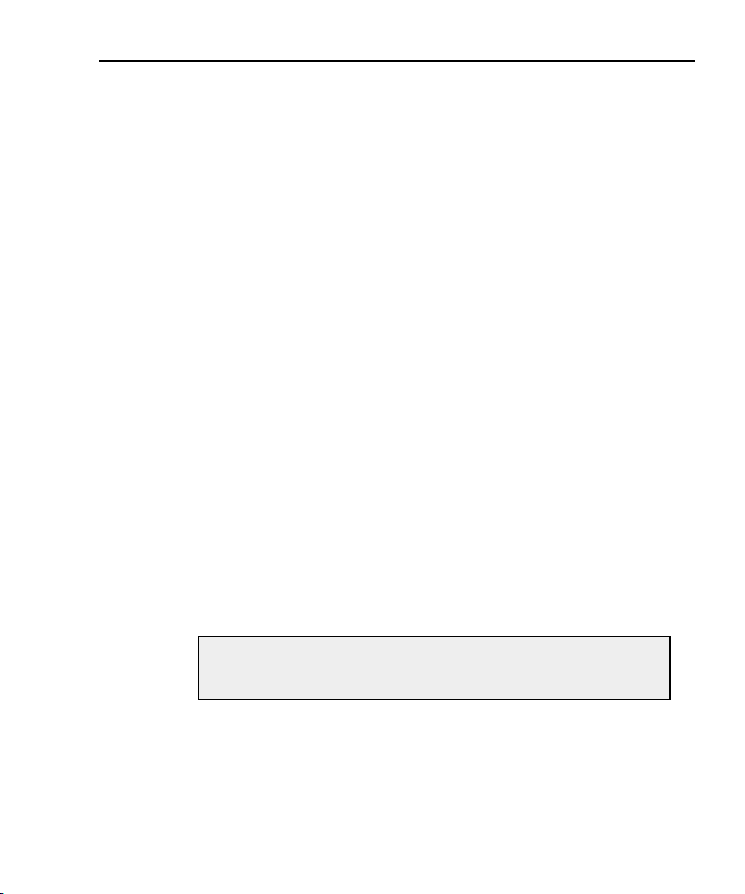
Model 6220/6221 User’s Manual DC Current Source Operation 3-13
Remote programming – Autorange can be used when setting the I-source
value. With autorange enabled, the Model 622x will automatically select the
optimum (lowest) range to accommodate the source value.
The commands to select the source range, and set the output and
compliance values are provided in Table 3-2. The following examples
demonstrate proper syntax.
Example – Select the 20mA source range, set the source to output 12mA,
and set compliance to 10V:
CURRent:RANGe 12e-3 ‘ Selects the 20mA range.*
CURRent 12e-3 ‘ Sets the DC output to 12mA.
CURRent:COMPliance 10 ‘ Sets voltage compliance to 10V.
* To select a fixed source range, specify a parameter value that is the same as
the current output value to be sourced. For the parameter value “12e-3”, the
Model 622x selects the lowest range (20mA) that will accommodate a 12mA
output.
3. If desired, change the output response.
For the Models 6220 and 6221, an analog output filter can be enabled to
slow down the output response. For the Model 6221, the output response
can be set to FAST or SLOW. See “Output response”, page 3-5 for details
on setting the output response.
Analog filter – Use the FILT key to toggle the state (on or off) of the
low-pass filter. When this key is first pressed, the message “FILTER ON”
will be briefly displayed and the “FILT” annunciator turns on. To disable the
filter, again press the FILT key (“FILT” annunciator turns off).
Response speed setting (6221) – The response speed can only be
changed while the output is off. Response speed is set as follows:
a. Press the CONFIG key and then the OUTPUT key to display the output
response menu.
NOTE If the output was on when attempting to access the out-
put response menu, the output will turn off. Repeat step
a above to access the output response menu.
b. Using the controls for “Menu navigation” on page 1-14, select the FAST
or SLOW (6220 STYLE) response speed.
For remote programming, the commands to set output response are
shown in Table 3-2. The following example demonstrates proper syntax.
Return to Section 3 topics
Page 60

3-14 DC Current Source Operation Model 6220/6221 User’s Manual
Example – Enables the analog filter and, for the Model 6221, sets the
output response to fast:
CURRent:FILTer ON ‘ Enables the analog filter.
OUTPut:RESPonse FAST ‘ Sets the output response of the 6221 to FAST.
4. Turn on the output.
NOTE In order to turn on the output, an interlock switch must be
connected to the INTERLOCK connector on the rear panel of the Model 622x. Closing the interlock switch will enable the OUTPUT allowing it to be turned on. For details,
see “INTERLOCK” on page 2-4.
The OUTPUT key toggles the output state (on or off). When the output is
turned on, the OUTPUT indicator light turns on.
For remote programming, the command to control the output is shown in
Tab le 3- 2. The following example demonstrates proper syntax.
Example – Turns the output on:
OUTPut ON ‘ Turns output on.
The OUTPUT indicator will blink if the current source goes into compliance.
This indicates that the set current is not being delivered to the load. See
“Compliance” on page 3-3 for details.
Return to Section 3 topics
Page 61

Model 6220/6221 User’s Manual DC Current Source Operation 3-15
Remote programming – source output commands
Tab le 3- 2 lists the commands to configure and control the DC output. A program-
ming example to output DC current is also provided.
Table 3-2
DC output commands
Command Description Default
CLEar Turns output off and sets output level to zero.
CURRent:RANGe <n> Sets current source range (amps).
<n> = -105e-3 to 105e-3
CURRent:RANGe:AUTO <b> Enables or disables source autorange.
<b> = ON or OFF
CURRent <n> Sets DC current source output level (amps).
<n> = -105e-3 to 105e-3
CURRent:COMPliance <NRf> Sets voltage compliance (volts).
<NRf> = 0.1 to 105
CURRent:FILTer <b> Enables or disables the output analog filter.
<b> = ON or OFF
OUTPut:RESPonse <name> Select fast or slow output response speed for 6221.
<name> = FAST or SLOW
OUTPut <b> Turn output on or off.
<b> = ON or OFF
SourceMeter Sets output to zero, then turns the output off
3, 4
1, 2
100e-3
OFF
0.0
10.0
OFF
FAST
OFF
4
1. To select a fixed source range, specify the current output value that is going to
be sourced. The Model 622x will go to the lowest range that can source that
value. For example, If you are going to source 25mA, let <n> = 25e-3. The
100mA range will be selected.
2. Selecting a fixed source range disables autorange.
3. The output must be off in order change the output response. Sending this
command while the output is on will generate error -220 Execution Error.
4. OUTP OFF turns the output off, but does change the set output level.
SOUR:CLE sets the output level to zero and then turns the output off.
Return to Section 3 topics
Page 62

3-16 DC Current Source Operation Model 6220/6221 User’s Manual
Programming example
The following programming example shows a typical command sequence to configure and control the DC output:
CLEar ‘ Turns the output off.
CURRent:RANGe:AUTO ON ‘ Enables autorange.
CURRent 12e-3 ‘ Sets output level to +12mA.
CURRent:COMPliance 10 ‘ Sets voltage compliance to 10V.
OUTPut ON ‘ Turns the output on.
OUTPut OFF ‘ Turns the output off.
Applications
Some applications for the Model 622x are summarized below. See Appendix E of
the Reference Manual for details on these applications.
• Calibration source – Explains how to use Model 622x as a current calibration source. The custom sweep function allows a user-defined list of current
source values to be stored in memory. During the calibration process, each
current source level is output in the order that it appears in the list.
• Resistivity measurements – Certain semiconductor materials such as silicon have high resistivities. The Model 622x can be used to source stable
and accurate current, and the Keithley 6514 Electrometer can be used to
provide an accurate voltage measurement. Resistivity is then calculated.
• Diode characterization – With the Model 622x and Keithley 6514 Electrometer, it is possible to plot I-V (current-voltage) characteristics of a diode
over several decades. The Model 6514, with its high input resistance, will
allow the voltage measurement to be accurately made.
• Transistor characterization – The Model 622x can be used with a Keithley
24xx SourceMeter to characterize a device’s electrical DC parameters. The
Model 622x Current Source is configured to sweep a number of base currents for the test. The Model 24xx SourceMeter is configured to sweep voltage and measure current.
• External user-supplied filter – Based on load impedance and response
time requirements, a user-supplied filter can be effective at reducing high
frequency noise generated by the Model 622x current source.
• Compliance overshoot prevention – Depending on range and load
impedance, step changes in current could cause the output voltage to
briefly overshoot its set compliance level by as much as 2V and take several microseconds to settle. A few microseconds of overshoot could be
enough to damage voltage sensitive devices.
Return to Section 3 topics
Page 63
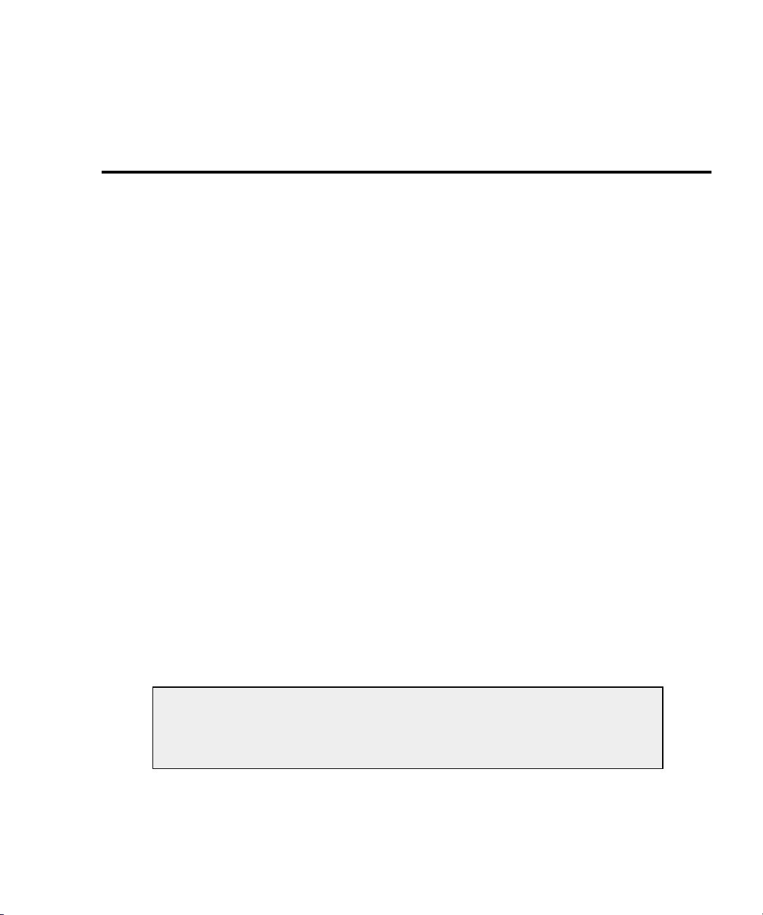
Section 4 topics
Sweep overview, page 4-2
Linear staircase sweep, page 4-2
Logarithmic staircase sweep, page 4-2
Custom sweep, page 4-2
Sweep characteristics, page 4-4
Custom sweep editing, page 4-4
Using auto-copy with custom sweeps, page 4-4
Source ranging, page 4-4
Sweep delay, page 4-5
Front panel sweep operation, page 4-5
Using the sweep configuration menu, page 4-5
Performing a staircase sweep, page 4-6
Running a staircase sweep, page 4-9
4
Sweeps
Remote sweep operation, page 4-8
Running a staircase sweep, page 4-9
Running a custom sweep, page 4-10
SCPI commands — sweeps, page 4-11
NOTE The information in this section is an abbreviated version of
the information in Section 4 of the Reference Manual. Refer to
Section 4 of the Reference Manual for complete details and
additional information that is not provided in this manual.
Page 64

4-2 Sweeps Model 6220/6221 User’s Manual
Sweep overview
As shown in Figure 4-1, the Model 622x Current Source can generate three types
of DC current sweeps.
NOTE User setups cannot be saved or recalled while a sweep is
armed or running. Attempting to do so will generate error
+413 Not allowed with mode arm.
Linear staircase sweep
With this sweep type, the current increases or decreases in specific steps, beginning with a start current and ending with a stop current. Figure 4-1A shows an
increasing linear staircase sweep from a 1mA start current to a 5mA stop current
in 1mA steps. The bias current is the fixed current setting just prior to the start of
the sweep. The current output will remain at the last point in the sweep after completion.
Logarithmic staircase sweep
In this case, the current increases or decreases logarithmically, beginning with a
start current and ending with a stop current. Figure 4-1B shows an increasing log
staircase sweep from a 0.1mA start current to a 100mA stop current with logarithmic steps. Again, the bias current is the fixed current setting just prior to the start
of the sweep. The current output will remain at the last point in the sweep after
completion.
Custom sweep
The custom sweep allows you to program arbitrary sweep steps anywhere within
the output current range of the Model 622x. Figure 4-1C shows a typical custom
sweep with arbitrary steps. As with the other two sweep types, the bias current is
the fixed current setting just prior to the start of the sweep. The current output will
remain at the last point in the sweep after completion.
NOTE A custom sweep cannot be saved as a user setup.
Attempting to do so will generate error +528 Cannot save
CUSTOM sweep setup.
Return to Section 4 topics
Page 65
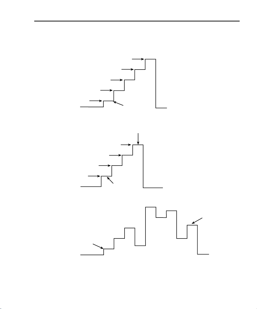
Model 6220/6221 User’s Manual Sweeps 4-3
Figure 4-1
Comparison of sweep types
A. Linear Staircase Sweep
5mA (Stop)
4mA
3mA
2mA
1mA
Bias
B. Logarithmic Staircase Sweep
100mA
Start
0mA
Stop
10mA
1mA
0.1mA
Bias
C. Custom Sweep
First Point
Bias
Start
Logarithmic scale
shown for
staircase steps.
0mA
Last Point
0mA
Return to Section 4 topics
Page 66

4-4 Sweeps Model 6220/6221 User’s Manual
Sweep characteristics
NOTE Jitter – Step-to-step sweep timing may jitter as much as 1ms.
This jitter can be eliminated by disabling the front panel. For
details, see “Step-to-step timing jitter” on page 1-12.
Custom sweep editing
A typical custom sweep editing display is shown below:
P12345: +1.234567 mA
Del:123456.789s Cmpl:100.00 V
The leftmost value on the top line is the point number, and the next value is the
actual current setting. The formatting also shows the current range. The bottom
line values are delay in seconds and compliance. Before entering this display, use
the #-POINTS menu to select the number of sweep points. The editing for the custom sweep point adjust menu will not accept values above the number of points
selected.
Using auto-copy with custom sweeps
An “auto-copy” feature is included to help reduce keystrokes when editing custom
sweeps. If auto-copy is enabled, whenever a point is entered (by pressing the
ENTER key), the compliance and delay values will automatically be copied to all
higher-numbered points in the list.
Source ranging
The source ranging setting determines how the Model 622x selects the current
range based on the sweep steps as follows:
• BEST — With this option, the unit will select a single fixed source range
that will accommodate all of the source levels in the sweep.
• AUTO — With this option, the Model 622x will select the most sensitive
source range for each source level in the sweep. Note that the output current goes to zero during the range change.
• FIXED — With this option, the source remains on the range it is on when
the sweep is started. For sweep points that exceed the source range capability, the source will output the maximum level for that range.
Return to Section 4 topics
Page 67

Model 6220/6221 User’s Manual Sweeps 4-5
Sweep delay
The sweep delay parameter determines how long the Model 622x will remain on
each sweep step once the output current is set to the step value. For linear and
logarithmic staircase sweeps, the sweep delay period is the same for every step in
the sweep. For customs sweeps, the sweep delay for each step can be independently programmed.
The programmable range for the sweep delay is from 0.001s to 999999.999s.
Front panel sweep operation
Using the sweep configuration menu
To configure sweeps, press CONFIG then SWP, then make your selections from
Tab le 4- 1 below. See the detailed procedures for each sweep type below.
Tab le 4- 1
Sweep configuration menu
Menu selection Description
TYPE
STAIR
LOG
CUSTOM
SWEEP-COUNT
FINITE
INFINITE
SOURCE-RANGING
BEST
AUTO
FIXED
COMPLIANCE-ABORT
NO
YES
* Select AUTO COPY ON to automatically copy delay and compliance values to all sweep points.
Return to Section 4 topics
Select sweep type:
Set START, STOP, STEP, DELAY.
Set START, STOP, NO OF POINTS, DELAY.
Set #-POINTS, ADJUST POINTS, AUTO
COPY*.
Choose sweep count:
Enter desired # of sweeps.
Continuously repeating sweeps.
Select source ranging:
Use best range based on maximum sweep step.
Auto range based on individual sweep step.
Always stay on fixed source range.
Select compliance abort mode:
Do not abort sweep if compliance reached.
Abort sweep if compliance reached.
Page 68

4-6 Sweeps Model 6220/6221 User’s Manual
Performing a staircase sweep
1. Configure source functions:
a. If desired, set the bias current (output current prior to the start of the
sweep) by pressing the DC key and then setting the current to the
desired value.
b. Select the compliance display field, then set the voltage compliance as
appropriate for expected sweep parameters.
2. Configure the sweep as follows:
a. Press CONFIG then SWP to enter the sweep configuration menu.
b. Select TYPE, then press ENTER.
c. Select STAIR or LOG, then press ENTER to choose a linear staircase
sweep.
d. For STAIR sweeps, enter the desired START, STOP, STEP, and DELAY
values. For LOG sweeps, enter the desired START, STOP, NO OF
POINTS, and DELAY values.
e. From the CONFIGURE SWEEPS menu, select SWEEP-COUNT, press
ENTER, then choose FINITE or INFINITE as desired.
f. Again from the CONFIGURE SWEEPS menu, choose
SOURCE-RANGING, press ENTER, then select BEST, AUTO, or
FIXED as appropriate.
g. From the CONFIGURE SWEEPS menu, select COMPLIANCE-
ABORT, press ENTER, then choose to abort (YES) or not to abort (NO)
the sweep if compliance is reached while the sweep is in progress.
h. Press EXIT to return to normal display.
3. Run sweep:
a. Press the SWP key to arm the sweep. The output will turn on.
b. Press TRIG to start the sweep.
c. Press EXIT to abort the sweep before it is finished.
d. Turn the output off by pressing the ON/OFF OUTPUT key when the
sweep is finished.
Return to Section 4 topics
Page 69

Model 6220/6221 User’s Manual Sweeps 4-7
Performing a custom sweep
1. Configure the bias current (output current prior to the start of the sweep) by
pressing the DC key and then setting the current to the desired value.
2. Configure the sweep as follows:
a. Press CONFIG then SWP to enter the sweep configuration menu.
b. Select TYPE, then press ENTER.
c. Select CUSTOM, then press ENTER to choose a custom sweep.
d. Select #-POINTS, press ENTER, then enter the number of sweep
points (64,000 maximum).
e. Choose AUTO-COPY, press ENTER, then enable (YES) or disable
(NO) auto copy. With auto copy enabled, compliance and delay values
are automatically copied to all sweep point locations.
f. Select ADJUST-POINTS, then set the current value, compliance, and
delay for the first sweep point.
g. Set the current value, compliance (if not using auto-copy), and delay for
each remaining sweep point.
h. From the CONFIGURE SWEEPS menu, select SWEEP-COUNT, press
ENTER, then choose FINITE or INFINITE as desired.
i. Again from the CONFIGURE SWEEPS menu, choose
SOURCE-RANGING, press ENTER, then select BEST, AUTO, or
FIXED as appropriate.
j. From the CONFIGURE SWEEPS menu, select COMPLIANCE-
ABORT, press ENTER, then choose to abort (YES) or not to abort (NO)
the sweep if compliance is reached while the sweep is in progress.
k. Press EXIT to return to normal display.
3. Run sweep:
a. Press the SWP key to arm the sweep. The output will turn on.
b. Press TRIG to start the sweep.
c. Press EXIT to abort the sweep before it is finished.
d. Turn the output off by pressing the ON/OFF OUTPUT key when the
sweep is finished.
Return to Section 4 topics
Page 70

4-8 Sweeps Model 6220/6221 User’s Manual
Remote sweep operation
Procedures for programming and running a sweep are shown on the following
pages. Each of these procedures includes commands for a typical sweep example. Table 4-2 summarizes parameters for each of these examples. See “SCPI
commands — sweeps,” page 4-11 for listings of sweep commands.
Tab le 4- 2
Sweep example parameters
Sweep type Parameters for sweep examples
Linear staircase sweep (page 4-9) Start current: 1mA
Stop current: 10mA
Step current: 1mA
Delay: 1s
Source range: best fixed
Compliance abort: off
Sweep count: 1
Bias current: 100μA
Compliance: 10V
Custom (list) sweep (page 4-10) # points: 5
Points: 3mA, 1mA, 4mA, 5mA, 2mA
Delay: 3s, 1s, 4s, 5s, 2s
Compliance: 3V, 1V, 4V, 5V, 2V
Source range: auto
Compliance abort: off
Sweep count: 1
Bias current: 50μA
Return to Section 4 topics
Page 71

Model 6220/6221 User’s Manual Sweeps 4-9
Running a staircase sweep
1. Configure source functions.
Examples – The following commands restore defaults, set the bias current
to 100μA, and the compliance to 10V:
*RST ‘ Restore 622x defaults.
SOUR:CURR 1e-4 ‘ Set bias current to 100μA
SOUR:CURR:COMP 10 ‘ Set compliance to 10V.
2. Configure the sweep.
Examples – The following commands configure a single linear staircase
sweep from 1mA to 10mA with 1mA steps using a 1s delay, best fixed
source range, and compliance abort disabled:
SOUR:SWE:SPAC LIN ‘ Select linear staircase sweep.
SOUR:CURR:STAR 1e-3 ‘ Set start current to 1mA.
SOUR:CURR:STOP 1e-2 ‘ Set stop current to 10mA.
SOUR:CURR:STEP 1e-3 ‘ Set step current to 1mA.
SOUR:DEL 1 ‘ Set delay to 1s.
SOUR:SWE:RANG BEST ‘ Select best fixed source range.
SOUR:SWE:COUN 1 ‘ Set sweep count to 1.
SOUR:SWE:CAB OFF ‘ Disable compliance abort.
3. Arm and run the sweep:
SOUR:SWE:ARM ‘ Arm sweep, turn on output.
INIT ‘ Trigger sweep.
4. When the sweep is done, turn the source output off with this command:
OUTP OFF
Return to Section 4 topics
Page 72

4-10 Sweeps Model 6220/6221 User’s Manual
Running a custom sweep
1. Configure source functions.
Examples – The following commands restore defaults and set the bias
current to 50μA:
*RST ‘ Restore 622x defaults.
SOUR:CURR 5e-5 ‘ Set bias current to 50μA
2. Configure the sweep.
Examples – The following commands configure a single custom sweep
with five points, different delay and compliance settings for each point, auto
source range, and compliance abort disabled:
SOUR:SWE:SPAC LIST ‘ Select custom sweep.
SOUR:SWE:RANG AUTO ‘ Select auto source range.
SOUR:LIST:CURR 3e-3,1e-3,4e-3,
5e-3,2e-3
SOUR:LIST:DEL 3,1,4,5,2 ‘ Delay points: 3s, 1s, 4s, 5s, 2s.
SOUR:LIST:COMP 3,1,4,5,2 ‘ Compliance = 3V, 1V, 4V, 5V, 2V.
SOUR:SWE:COUN 1 ‘ Set sweep count to 1.
SOUR:SWE:CAB OFF ‘ Disable compliance abort.
3. Arm and run the sweep:
SOUR:SWE:ARM ‘ Arm sweep, turn on output.
INIT ‘ Trigger sweep.
4. When the sweep is done, turn the source output off with this command:
‘‘Sweep points: 3mA, 1mA, 4mA,
5mA, 2mA.
OUTP OFF
Return to Section 4 topics
Page 73
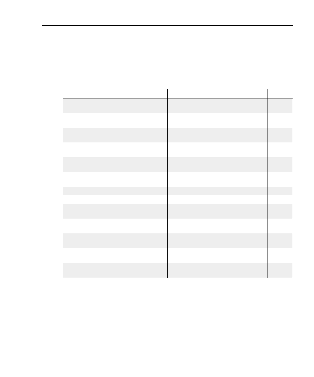
Model 6220/6221 User’s Manual Sweeps 4-11
SCPI commands — sweeps
Commands for linear and logarithmic staircase sweeps are listed in Table 4-3,
while commands for custom (list) sweeps are listed in Table 4-4.
Tab le 4- 3
Staircase sweep commands (linear and logarithmic)
Command Description Default
SOURce[1]:CURRent:STARt <n> Sets start current.
<n> = -0.105 to 0.105 (A)
SOURce[1]:CURRent:STOP <n> Sets stop current.
<n> = -0.105 to 0.105 (A)
SOURce[1]:CURRent:STEP <n> Sets step current.
<n> = 1e-13 to 0.105 (A)
SOURce[1]:CURRent:CENTer <n> Sets center current.
<n> = -0.105 to 0.105 (A)
SOURce[1]:CURRent:SPAN <n> Sets span current.
<n> = 2e-13 to 0.210 (A)
SOURce[1]:DELay <n> Sets source delay.
<n> = 0.001 to 999999.999 (s)
SOURce[1]:SWEep:ARM Prepare for running the sweep.
SOURce[1]:SWEep:ABORt Abort sweep immediately.
SOURce[1]:SWEep:SPACing <name> Selects sweep type.
<name>=LINear, LOGarithmic, or LIST
SOURce[1]:SWEep:POINts <n> Sets sweep points.
<n> = 1 to 65535
SOURce[1]:SWEep:RANGing <name> Selects sweep source ranging.
<name>=AUTO, BEST, or FIXed
SOURce[1]:SWEep:CABort <b> Sets compliance sweep abort state.
<b> = ON or OFF
SOURce[1]:SWEep:COUNt <NRf> Sets sweep count.
<NRf> = 1 to 9999 or INFinite
0
0.1
1e-2
0
0.1
1
LINear
11
BEST
OFF
1
Return to Section 4 topics
Page 74
4-12 Sweeps Model 6220/6221 User’s Manual
Table 4-4
Custom (list) sweep commands
Command Description
SOURce[1]:LIST:CURRent <NRf>
[,<NRf>, ...<NRf>]
SOURce[1]:LIST:CURRent:APPend <NRf>
[,<NRf>, ...<NRf>]
SOURce[1]:LIST:DELay <NRf>
[,<NRf>, ...<NRf>]
SOURce[1]:LIST:DELay:APPend <NRf>
[,<NRf>, ...<NRf>]
SOURce[1]:LIST:COMPliance <NRf>
[,<NRf>, ...<NRf>]
SOURce[1]:LIST:COMPliance:APPend <NRf>
[,<NRf>, ...<NRf>]
SOURce[1]:LIST:CURRent:POINts? Query # of current list points.
SOURce[1]:LIST:DELay:POINts? Query # of delay list points.
SOURce[1]:LIST:COMPliance:POINts? Query # of delay list points.
Defines list of currents.
<NRf> = -0.105 to 0.105 (A)
Adds current points to existing list.
<NRf> = -0.105 to 0.105 (A)
Defines list of delay values.
<NRf> = 0 to 999.9999 (s)
Adds to list of delay values.
<NRf> = 0.001 to 999999.999 (s)
Defines list of compliance values.
<NRf> = 0.1 to 105 (V)
Adds to list of compliance values.
<NRf> = 0.1 to 105 (V)
Return to Section 4 topics
Page 75
Delta, Pulse Delta, and
Differential Conductance
Section 5 topics
Operation overview, page 5-2 Delta, page 5-13
Model 622x measurement process, page 5-13
Test systems, page 5-4 Configuration settings, page 5-15
Keithley instrumentation requirements, page 5-4 Operation, page 5-16
System configurations, page 5-4 Setup and arm commands, page 5-19
System connections, page 5-5
DUT test connections, page 5-8 Pulse Delta, page 5-21
Configuring communications, page 5-9 Model 6221 measurement process, page 5-21
Triggering sequence, page 5-10 Pulse Delta outputs, page 5-22
Configuration settings, page 5-26
Readings, page 5-11 Operation, page 5-29
Display readings, page 5-11 Setup commands, page 5-32
Measurement units, page 5-11
Read commands, page 5-13 Differential Conductance, page 5-34
Model 622x measurement process, page 5-34
Configuration settings, page 5-37
Operation, page 5-38
Setup and arm commands, page 5-41
5
NOTE The information in this section is an abbreviated version of
the information in Section 5 of the Reference Manual. Refer to
Section 5 of the Reference Manual for complete details and
additional information that is not provided in this manual.
Page 76

5-2 Delta, Pulse Delta, and Differential Conductance Model 6220/6221 User’s Manual
Operation overview
The Model 6220 or 6221 Current Source can be used with a Model 2182/2182A
Nanovoltmeter to perform Delta and Differential Conductance. The
Model 6221/2182A combination can also perform Pulse Delta. These operations
use a delta current-reversal technique to cancel the effects of thermal EMFs.
The Model 622x provides a bipolar output current and the Model 2182/2182A performs A/D conversions (measurements) at source high and source low points. An
averaging algorithm is then used to calculate the delta reading.
Delta – The Model 622x provides a square wave current output, and the Model
2182/2182A performs A/D conversions (measurements) at each high and low output level. A 3-point moving-average algorithm is used to calculate Delta readings.
As shown in Figure 5-1A, the first three Model 2182/2182A A/D conversions (measurements) yield the first Delta reading. Each subsequent Model 2182/2182A A/D
conversion then yields a single Delta reading. Every Delta reading uses the three
previous A/Ds to calculate Delta.
Pulse Delta – The Model 6221 outputs pulses and uses 3-point repeatingaverage measurements to calculate Pulse Delta voltage. For each pulse, the
Model 2182A performs an A/D conversion (measurement) at pulse low, pulse
high, and pulse low. Each set of three A/D readings yield a single Pulse Delta
reading. Figure 5-1B shows Pulse Delta measurements. If device heating is a
concern, 2-point measurements can instead be used (2nd low pulse not
measured due to corruption from heat).
Differential Conductance – The Model 622x outputs a differential current (dI)
sweep and measures differential voltage (dV). This function uses a 3-point
moving average algorithm to calculate dV. With dI known and dV calculated, the
Model 622x can then calculate differential conductance (dG) or differential resistance (dR). Figure 5-1C shows Differential Conductance measurements.
NOTE Jitter – For Delta and Differential Conductance, step-to-
step timing may jitter as much as 1ms. This jitter can be
eliminated by disabling the front panel. For details, see
“Step-to-step timing jitter” on page 1-12.
Return to Section 5 topics
Page 77
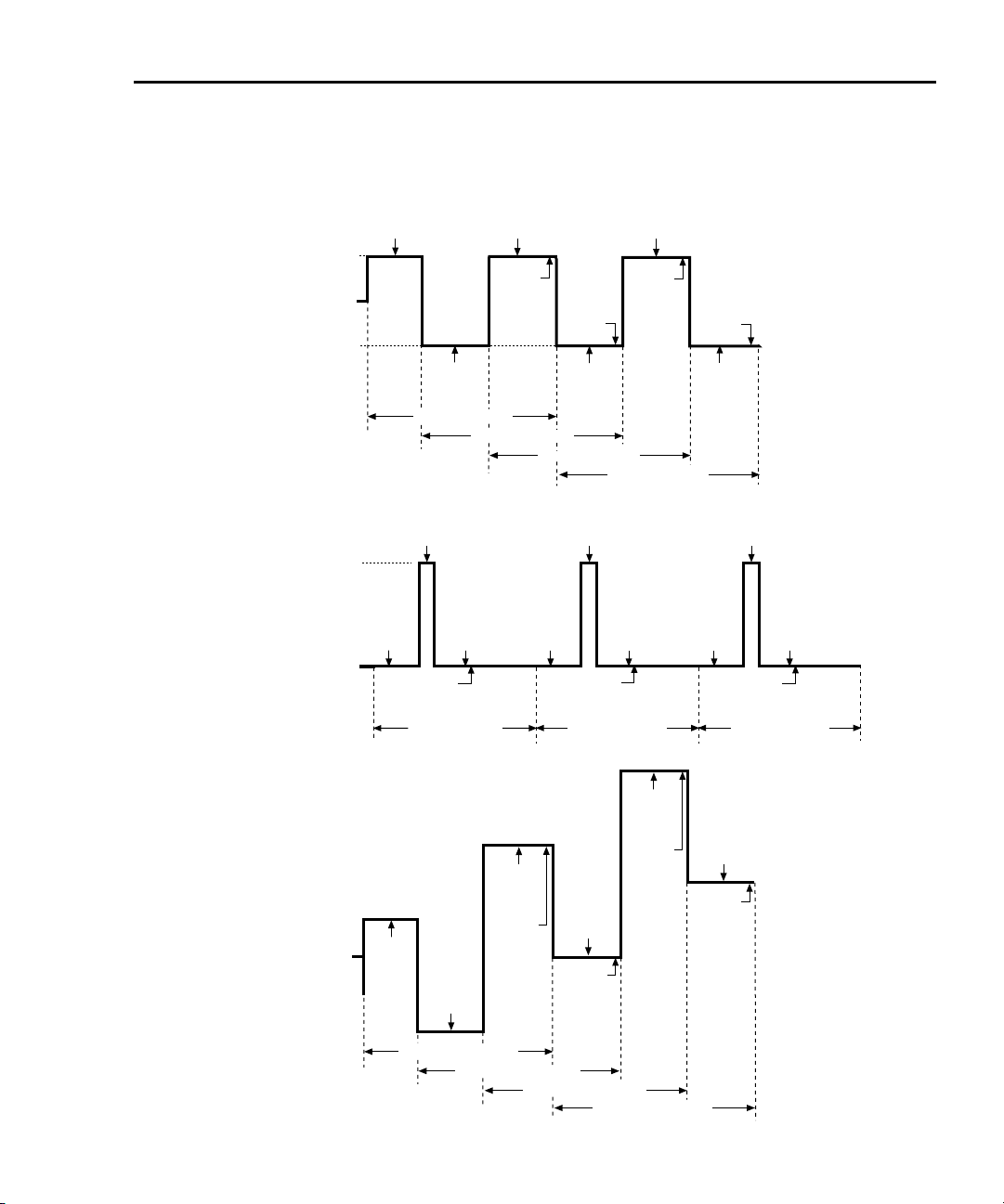
Model 6220/6221 User’s Manual Delta, Pulse Delta, and Differential Conductance 5-3
Figure 5-1
Delta, Pulse Delta, and Differential Conductance measurements
A) Delta measurements
2182/2182A
A/D
I-High
622x
0
I-Source
I-Low
2182/
2182A
A/D
1st Delta Cycle
B) Pulse Delta measurements
2182A
A/D
I-High
6221
I-Source
I-Low
2182A
A/D
Pulse Delta
2182A
Reading
1st
1st Pulse Delta
Cycle
A/D
2182/2182A
A/D
DE LTA
Reading
1st
2nd Delta Cycle
3rd Delta Cycle
2182A
A/D
Pulse Delta
DE LTA
Reading
2nd
2182/
2182A
A/D
4th Delta Cycle
2182A
A/D
2182A
A/D
Reading
2nd
2nd Pulse Delta
Cycle
2182/2182A
A/D
DE LTA
Reading
3rd
DE LTA
Reading
4th
2182/
2182A
A/D
2182A
2182A
A/D
Pulse Delta
Reading
Nth
3rd Pulse Delta
A/D
2182A
A/D
Cycle
C) Differential Conductance measurements
622x
I-Source
Start
2182/
2182A
A/D
2182/
2182A
1st Diff Cond Cycle
A/D
2182/
2182A
A/D
dV Calc
#1
dV Calc
2nd Diff Cond Cycle
3rd Diff Cond Cycle
Return to Section 5 topics
2182/
2182A
dV Calc
2182/
2182A
A/D
#2
4th Diff Cond Cycle
A/D
#3
2182/
2182A
A/D
dV Calc
#4
Page 78
5-4 Delta, Pulse Delta, and Differential Conductance Model 6220/6221 User’s Manual
Test systems
NOTE Supplied example software allows you to control Model
622x delta tests from any PC using simple mouse-clicks
through a virtual front panel. For details, see “Using the
example software” in Section 10 of the Reference
Manual.
Keithley instrumentation requirements
Keithley instrumentation requirements for Delta, Pulse Delta, and Differential Conductance are:
• Models 6220 and 2182 – Delta and Differential Conductance
• Models 6220 and 2182A – Delta and Differential Conductance
• Models 6221 and 2182 – Delta and Differential Conductance
• Models 6221 and 2182A – Delta, Pulse Delta, and Differential Conductance
NOTE The firmware version of the Model 2182 must be A10 or
higher.
The firmware version of the Model 2182A must be C01 or
higher.
System configurations
Stand-alone system
System configuration for stand-alone front panel operation is shown in
Figure 5-2A. The RS-232 interface for the Model 2182/2182A must be enabled
(on) and the selected interface for the Model 622x must be the GPIB or the
Ethernet (Model 6221).
PC control system
System configuration for PC control of the Model 622x is shown in Figure 5-2B.
The RS-232 interface for the Model 2182/2182A must be enabled (on) and the
selected interface for the Model 622x must be the GPIB or the Ethernet (Model
6221).
Return to Section 5 topics
Page 79
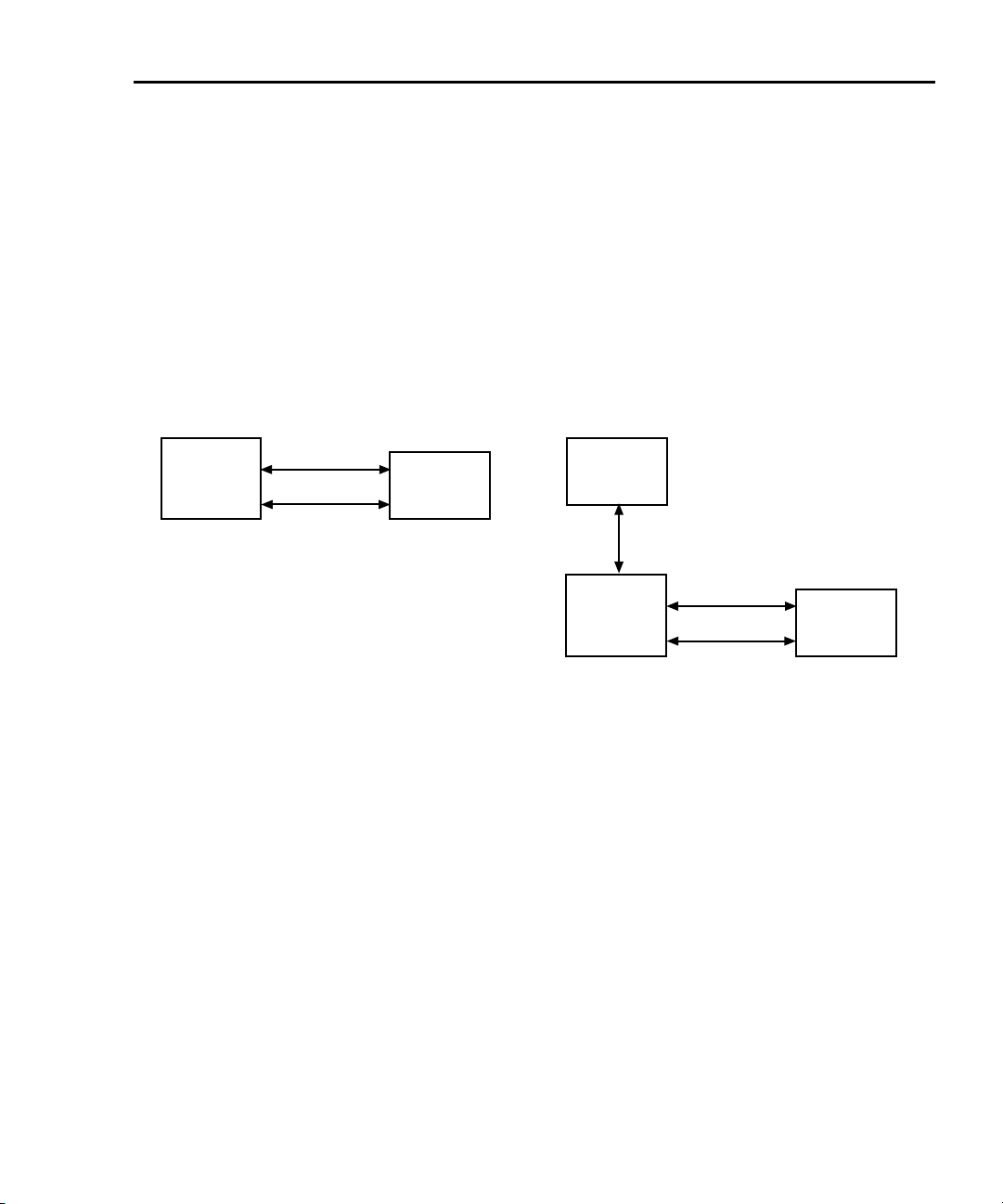
Model 6220/6221 User’s Manual Delta, Pulse Delta, and Differential Conductance 5-5
Serial communications
In order to perform Delta, Pulse Delta, or Differential Conductance measurements, the Model 622x must communicate to the Model 2182/2182A over the
serial (RS-232) interface. With serial communications properly configured and
connected, the Model 622x will automatically send setup commands to the
Model 2182/2182A when Delta, Pulse Delta, or Differential Conductance is
armed. When the test is started, readings from the Model 2182/2182A are automatically sent to the Model 622x to be processed into Delta, Pulse Delta, or Differential Conductance readings that are then stored in the buffer.
Figure 5-2
System configurations for Delta, Pulse Delta, and Differential Conductance
A) Stand-alone system (front panel operation)
Keithley
622x
GPIB or
Ethernet (6221)
Selected
Current Source
RS-232
(null-modem)
Trigger Link
Keithley
2182/2182A
RS-232 On
Nanovoltmeter
B) PC control of 6220/21
PC
IEEE-488
or
Ethernet (6221)
System connections
WARNING Before making or breaking system connections, the Models
622x and 2182/2182A, and the PC must be turned off and the
line cords must be disconnected from AC line power.
System connections depend on the system configuration being used (see
Figure 5-2). Connections for the two system configurations are explained as
follows.
Connections – stand-alone system
System connections for this configuration are shown in Figure 5-3.
RS-232 – The Model 622x communicates with the Model 2182/2182A via the
RS-232 interface. Make sure to use a null-modem RS-232 cable for this connection.
Keithley
622x
GPIB or
Ethernet (6221)
Selected
Current Source
RS-232
(null-modem)
Trigger Link
Keithley
2182/2182A
RS-232 On
Nanovoltmeter
Return to Section 5 topics
Page 80

5-6 Delta, Pulse Delta, and Differential Conductance Model 6220/6221 User’s Manual
Trigge r L i n k – The Trigger Link synchronizes triggering between the Current
Source and the Nanovoltmeter. Trigger Link connections assume that the Model
2182/2182A is using the factory default (hard-wired) configuration:
EXT TRIG (input) = line #2
VMC (output) = line #1)
Delta, Pulse Delta, and Differential Conductance will not work if the
Model 2182/2182A is not using the default Trigger Link configuration. See “Changing trigger link lines” in Section 5 (Disassembly) of the Model 2182/2182A Service
Manual.
Figure 5-3
System connections – stand-alone operation
Keithley 622x Current Source Keithley 2182/2182A Nanovoltmeter
iEEE-488
ETHERNET
RS-232
TRIGGER LINK
RS-232 Cable
(null-modem, male-to-male)
8501 Trigger Link Cable
TRIGGER
LINK
RS-232
iEEE-488
Connections – PC control system
System connections for this configuration are shown in Figure 5-4.
RS-232 and Trigger Link – This system configuration uses the same RS-232 and
Trigger Link connections that are used for stand-alone operation.
IEEE-488 or Ethernet (6221) – This system configuration uses a PC to communicate with the Model 622x. For the Model 6220, the IEEE-488 bus interface can be
used. For the Model 6221, the IEEE-488 bus or the Ethernet can be used. For the
Ethernet, make sure to use a cross-over Ethernet cable for direct connection to
the PC.
Return to Section 5 topics
Page 81

Model 6220/6221 User’s Manual Delta, Pulse Delta, and Differential Conductance 5-7
Figure 5-4
System connections – PC control of Model 622x
Keithley 622x Current Source Keithley 2182/2182A Nanovoltmeter
6220: GPIB selected
6221: GPIB or Ethernet selected
RS-232 On
TRIGGER
LINK
RS-232
iEEE-488
IEEE-488
Cable
iEEE-488
ETHERNET
RS-232
Ethernet Cross-over Cable
OR
(RJ-45 male/male)
(6221only)
TRIGGER LINK
RS-232 Cable
(null-modem, male-to-male)
8501 Trigger Link Cable
PC
Return to Section 5 topics
Page 82

5-8 Delta, Pulse Delta, and Differential Conductance Model 6220/6221 User’s Manual
DUT test connections
WARNING Before making or breaking test connections, the Models 622x
and 2182/2182A must be turned off and the line cords must be
disconnected from AC line power.
DUT test connections are shown in Figure 5-5. This connection scheme uses
Cable Guard and an earth grounded test fixture that is equipped with an interlock
switch. See Section 2 of this manual for connection information. See Section 2 of
the Reference Manual for details on the principles of Cable Guard and guidelines
for test fixture requirements.
Figure 5-5
Guarded test connections
NOTE For this connection scheme, the inner shield of the
Model 622x OUTPUT connector must be connected to the
driven guard. See “Triax inner shield” on page 2-6 for
details on connecting the inner shield of the OUTPUT
connector to Cable Guard.
Rear
Panel
Keithley 622x
Current Source
(Inner shield set
as Guard)
Triax Cable
WARNING
The voltage levels
on the Guard and
High terminals are
the same. A safety
hazard exists when
the OUTPUT is 30V
rms (42V peak) or
more.
INTERLOCK
connector
OUTPUT
connector
Guard
(Black)
Note
Interlock Cable
Interlock Switch
High
(Red)
DUT
Low
(Green)
The triax cable and input cable shown in this drawing are
supplied with the Keithley Models 622x and 2182/2182A.
Guard Plate
Test Fixture
WARNING
Keithley 2182/2182A
HI
LO
Nanovoltmeter
Connect test fixture to a known
safety earth ground using #18
AWG (or larger) wire.
Return to Section 5 topics
Front
Panel
2107
Input Cable
Channel 1
Page 83

Model 6220/6221 User’s Manual Delta, Pulse Delta, and Differential Conductance 5-9
Configuring communications
For both front panel and remote operation, the RS-232 of the Model 2182/2182A
must be enabled (on), and the selected communications interface for the Model
622x must be the GPIB or the Ethernet (Model 6221 only).
Model 2182/2182A communications
Configure the Model 2182/2182A for RS-232 communications as follows:
On the Model 2182/2182A, press the SHIFT key and then the RS-232 key to
access the RS-232 menu. From this menu, configure the RS-232 as follows:
1. Select ON for the RS-232 interface.
2. Select the 19.2K baud rate.
3. Select the NONE setting for flow control.
Details on setting communications are provided in the User’s Manual for the
Model 2182/2182A (in Section 11, see “Interface selection and configuration procedures”).
Model 622x communications
For Delta, Pulse Delta, and Differential Conductance, the Model 622x uses two
interfaces for communications. It uses the RS-232 to communicate with the Model
2182/2182A, and it uses the GPIB or Ethernet (Model 6221 only) to communicate
with the PC. For details on communications configuration for the Model 622x, see
Section 10 of the Reference Manual.
Configure the Model 622x for communications as follows:
1. RS-232 – On the Model 622x, press the COMM key and then select
RS-232 from the communications setup menu:
a. Set the BAUD rate to 19.2K.
b. Set FLOW CTRL (flow control) to NONE.
c. Press the ENTER key.
The Model 622x will reboot if RS-232 was not the previously selected
communications interface.
2. GPIB or Ethernet – The GPIB or the Ethernet (Model 6221 only) must be
the selected interface to allow communications with the PC.
On the Model 622x, press the COMM key and then select GPIB or
ETHERNET (6221 only) from the communications setup menu:
• GPIB – Set the IEEE-488 address (0 to 30).
• Ethernet (6221) – Set the IP, Gateway, Subnet, and DHCP.
After configuring the GPIB or Ethernet, press ENTER. The configured
communications interface will be selected and the Model 622x will reboot.
Return to Section 5 topics
Page 84

5-10 Delta, Pulse Delta, and Differential Conductance Model 6220/6221 User’s Manual
Arming and Starting the Test
Arming – After a delta test is configured, the test is armed by pressing the DELTA
key, PULSE key (Pulse Delta), or COND key (Differential Conductance). For
remote programming, the following commands are used to arm the test:
SOUR:DELT:ARM ‘ Arm Delta
SOUR:PDEL:ARM ‘ Arm Pulse Delta
SOUR:DCON:ARM ‘ Arm Differential Conductance
During the arming process, the Model 622x establishes communications with the
Model 2182/2182A and performs a series of operations. These arming operations
are covered in Section 5 of the Reference Manual.
Staring the test – An armed test can be started by pressing the TRIG key, or sending the :INIT IMM command. Details on running a test are provided in the individual “Operation” procedures for Delta, Pulse Delta, and Differential Conductance
later in this section.
Triggering sequence
The Trigger Link is used to synchronize source-measure triggering operations of
the Models 622x and 2182/2182A. General trigger sequence for delta tests:
1. Model 622x outputs a current step or pulse.
2. After allowing the output to settle, the Model 622x outputs a trigger to the
Model 2182/2182A to perform a measurement. The reading is sent back to
the Model 622x (via serial port).
3. The Model 2182/2182A sends a trigger to the Model 622x to output the
next current level or pulse.
4. Steps 2 and 3 are repeated until the test is finished.
While the test is running, the Model 622x will calculate Delta, Pulse Delta, or Differential Conductance from the readings it receives from the Model 2182/2182A.
The readings will be displayed and stored in the buffer.
Details on the “Trigger sequence” for Delta, Pulse Delta, and Differential Conductance are provided in Section 5 of the Reference Manual.
Return to Section 5 topics
Page 85
Model 6220/6221 User’s Manual Delta, Pulse Delta, and Differential Conductance 5-11
Readings
Display readings
Display reading examples:
+1.23456 nV Delta Delta voltage reading
+1.23456 Ω Delta Delta ohms reading
+1.23456 S D Cond Differential Conductance Siemens reading
+1.23456 mWp Pulse Pulse Delta peak power (Watts) reading
+1.23456 mW Pulse Pulse Delta average power (Watts) reading
1. Pulse Delta Power can be a peak power reading or an average power reading (see “Measurement units” in Section 5 of the Reference Manual).
2. For remote operation, the returned reading string for a Delta Pulse power
reading indicates if it is a peak or average reading. Use the UNIT:POWer?
command (see Tab l e 5 - 1 ) to determine if the power reading is peak or average.
3. When recalling buffer statistics (such as Average or Standard Deviation) for
Pulse Delta power readings, only the power units for the first stored reading
is checked to determine if it is a Peak or Average power reading. The result
of the buffer statistic will have the same units (W for Average or Wp for
Peak) as the first stored reading.
1, 2, 3
1, 2, 3
NOTE The SMPL annunciator blinks on and off for every other
reading that is acquired from the Model 2182/2182A.
Measurement units
Volts, ohms, power, or conductance
The readings from the Model 2182/2182A for Delta, Pulse Delta, or Differential
Conductance are sent to the Model 622x as voltage readings. These readings can
be displayed by the Model 622x as Volts (V), Ohms (Ω), power (Watts; W), or conductance (Siemens; S) readings.
Return to Section 5 topics
Page 86

5-12 Delta, Pulse Delta, and Differential Conductance Model 6220/6221 User’s Manual
The default units for the Model 622x is volts. With Ohms (Ω) units or Siemens (S)
units selected, a reading is calculated as follows:
Ω = V/I
S = I/V
Where: V is the Delta, Pulse Delta, or Differential Conductance voltage reading.
I is the current sourced by the Model 622x.
With Power units selected, power is calculated as follows:
Delta Pulse Delta
1
Differential Conductance
2
W = I x V W
W
= I x V W = I
PEAK
= I x V x Duty Cycle
AVG
AVG
x V
AVG
1. See Section 5 of the Reference Manual for details on “Peak power and
Average power” for Pulse Delta.
2. See Section 5 of the Reference Manual for details on “Average Voltage and
Power” for Differential Conductance.
Setting measurement units
From the front panel, units can be set as follows:
1. Press the UNITS key to display the READING UNITS menu.
2. Use the “Menu navigation” controls (see page 1-14) to select the desired
measurement units (VOLTS, OHMS, WATTS, or SIEMENS).
3. Model 6221 only – After selecting WATTS, you will be prompted to select
the POWER TYPE.
4. Select the desired power type (AVERAGE or PEAK).
Remote programming – Commands for setting units are listed in Table 5-1
Tab le 5- 1
Measurement unit commands
Command Description Default
UNIT[:VOLT][:DC] <name> Specify reading units*.
<name> = V, OHMS, W, or SIEMens
UNIT:POWer[:TYPE] <name> Set power units reading type for 6221
Pulse Delta.
<name> = AVERage or PEAK
UNIT:POWer[:TYPE]? Query power units reading type
* The <name> parameter for Siemens can be sent as S, SIEM, or SIEMENS.
V
PEAK
.
Example – Selects power (W) measurement units for the Model 622x:
UNIT W
Return to Section 5 topics
Page 87

Model 6220/6221 User’s Manual Delta, Pulse Delta, and Differential Conductance 5-13
Read commands
The Model 622x does not perform measurements. However, raw readings are
sent from the Model 2182/2182A to the Model 622x to calculate Delta, Pulse
Delta, or Differential Conductance readings. Readings from the Model 2182/
2182A are processed, stored, and displayed by the Model 622x.
The following read commands return pre-math readings and buffer readings.
Details on all read commands are provided in Section 5 of the Reference Manual.
Pre-math readings
SENSe[1]:DATA[:LATest]?
SENSe[1]:DATA:FRESh?
While Delta, Pulse Delta, or Differential Conductance is running, the
SENS:DATA:LATest? command can be sent to read the latest (last) pre-math
reading processed by the Model 622x. The returned reading will be filtered if the
averaging filter is enabled. If this read command is sent before a new reading is
available, the last reading will again be returned.
The SENS:DATA:FRESh? command is the same as the SENS:DATA:LATest?
command except that once a reading is returned, it cannot be returned again. This
read command guarantees that each reading gets returned only once. If a new
(fresh) reading is not available when SENS:DATA:FRESh? is sent, error -230 Data
corrupt or stale will occur.
Delta
Buffer readings
TRACe:DATA?
This is the read command to return all readings stored in the buffer. There are
also commands to determine the type of readings stored in the buffer, specify a
list of consecutive buffer readings to return, and to read the selected buffer statistic. See “Data flow and read commands” in Section 5 of the Reference Manual.
Model 622x measurement process
The Delta process is shown in Figure 5-6. As shown, three Model 2182/2182A
A/D conversions are performed to yield a single Delta reading. When Delta starts,
three Model 2182/2182A A/Ds (A, B, and C) are performed and the Delta reading
is calculated. After the first Delta cycle, the moving-average technique is then
used. As shown, a Delta reading is yielded for every subsequent
Model 2182/2182A A/D. The new A/D replaces the oldest A/D in the Delta
calculation.
Return to Section 5 topics
Page 88
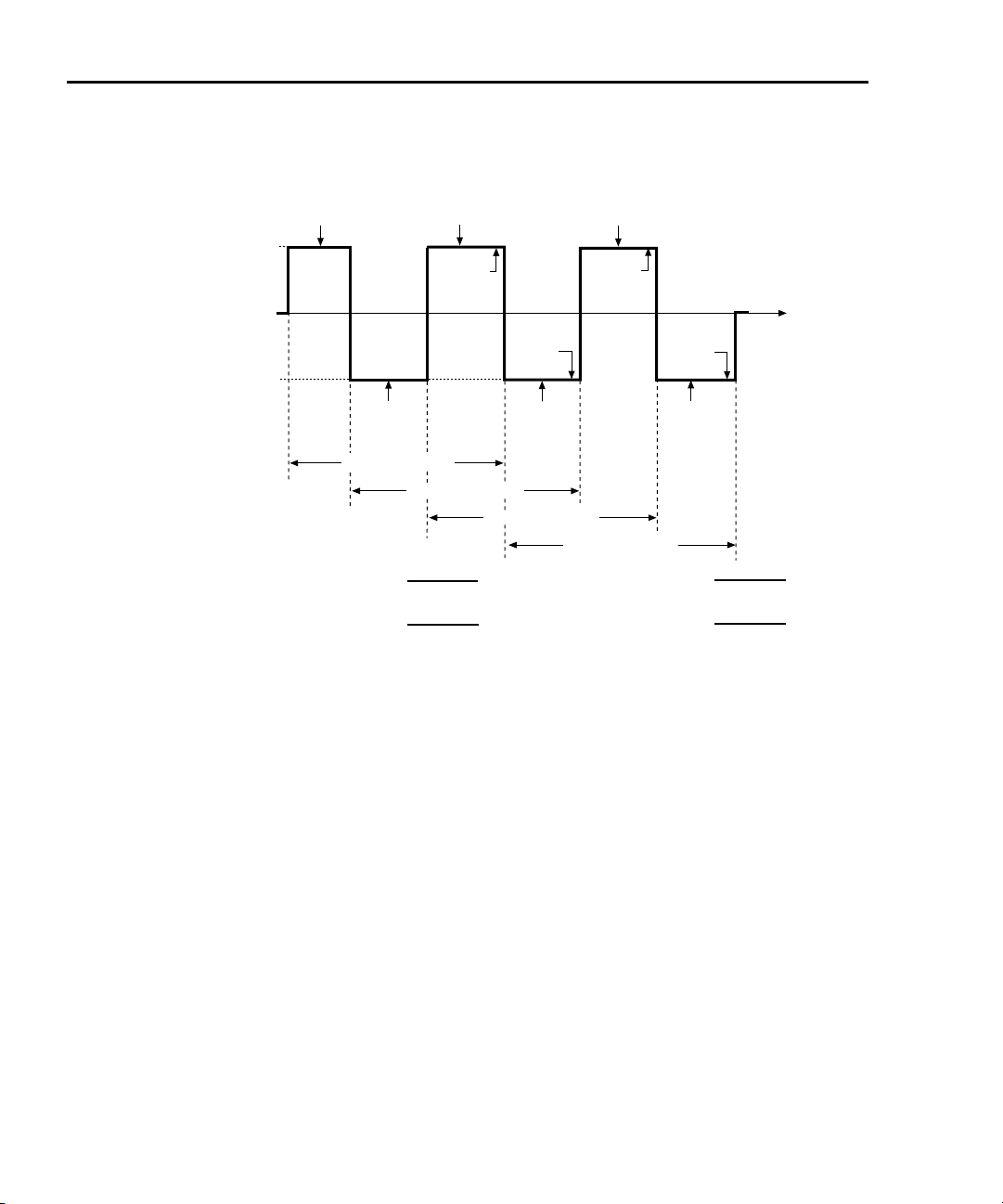
5-14 Delta, Pulse Delta, and Differential Conductance Model 6220/6221 User’s Manual
Figure 5-6
Delta measurement technique
2182/2182A
I-High
622x
I-Source
0
I-Low
1st Delta Reading =
2nd Delta Reading =
A/D A
2182/2182A
2182/
2182A
A/D B
1st Delta Cycle
2nd Delta Cycle
A - 2B + C
(
B - 2C + D
(
A/D C
DE LTA
Reading
1st
4
4
DE LTA
Reading
2182A
3rd Delta Cycle
(-1)
)
·
(-1)
)
·
2182/2182A
A/D E
DE LTA
Reading
2nd
2182/
A/D D
4th Delta Cycle
0
3rd Delta Reading =
1
4th Delta Reading =
3rd
DE LTA
Reading
4th
2182/
2182A
A/D F
C - 2D + E
(
D - 2E + F
(
The following equation can be used to calculate any Delta reading:
Delta
X2Y– Z+
⎛⎞
---------------------------
⎝⎠
4
n
1–()
•=
4
4
time
2
(-1)
)
·
3
(-1)
)
·
Where: X, Y, and Z are the three A/D measurements for a Delta reading.
n = Delta Cycle Number – 1
Example – Calculate the 21st Delta reading:
X, Y, and Z are the three A/D measurements for the 21st Delta reading.
n = Delta Cycle Number – 1
= 21 – 1
= 20
Therefore;
Delta
The (-1)
X2Y– Z+
⎛⎞
---------------------------
⎝⎠
4
X2Y– Z+
---------------------------=
4
n
term in the Delta calculation is used for polarity reversal of every other
20
1–()
•=
calculated Delta reading. This makes all calculated Delta readings in the test the
same polarity.
Return to Section 5 topics
Page 89

Model 6220/6221 User’s Manual Delta, Pulse Delta, and Differential Conductance 5-15
Measurement units
The fundamental measurement for Delta is voltage (Volts; V). However, the voltage reading can converted into a conductance (Siemens; S),
resistance (Ohms; Ω), or power (Watts; W) reading. See page 5-11 for details on
selecting “Measurement units”.
Configuration settings
Delta settings from the front panel are described as follows. These parameters are
set from the CONFIGURE DELTA menu that is accessed by pressing the CONFIG
key and then the DELTA key.
The equivalent remote programming commands to configure Delta are summarized in Table 5-2.
I-High and I-Low – These settings specify the high and low level for the square
wave output. When setting the I-High level, the I-Low level is set to the same magnitude but negative polarity. For example, setting I-High to 1mA sets I-Low to
-1mA. Setting the I-Low level has no affect on I-High.
I-High can be set from 0 to +105mA, and I-Low can be set from 0 to -105mA. The
default settings for high and low are +1mA and -1mA.
Delay – The Delta delay occurs after a trigger from the Model 2182/2182A is
received and is typically used to allow the current source to settle after changing
polarity. Delay can be set from 0.001 to 9999.999s. The default delay is 2ms.
Count – Delta count specifies the number of Delta readings to perform. Delta
count can be set to a finite number (1 to 65,536) or Infinity can be selected. With
an infinite count selected, the Delta runs continuously. The default count setting is
Infinity. The separate sweep count parameter can also be specified to control the
number of measurement sets, each composed of delta count readings, that are
repeated under trigger model control (see Section 8 of the Reference Manual).
Each set is run independently by restarting the delta mode's advanced moving average algorithm.
Compliance Abort – By enabling (YES) Compliance Abort, Delta operation will
abort if the current source goes into compliance. By default, Compliance Abort is
disabled (NO).
Cold Switching Mode – By enabling (YES) Cold Switching, Delta operation will
zero the current source before leaving the trigger layer prior to sequential trigger
model iterations. By default, Cold Switching is disabled (NO).
Return to Section 5 topics
Page 90

5-16 Delta, Pulse Delta, and Differential Conductance Model 6220/6221 User’s Manual
Operation
Delta operation – front panel
The system configuration for front panel stand-alone operation is shown in
Figure 5-2A on page 5-5.
1. Connections are shown in the following illustrations. All power must be
removed from all components in the system before making connections:
• Figure 5-3, page 5-6 – System connections
• Figure 5-5, page 5-8 – DUT test connections
2. Configure communications for the Models 2182/2182A and 622x as
explained in “Configuring communications,” page 5-9.
3. On the Model 2182/2182A, select the desired measurement range (using
the RANGE keys) and the integration rate (using the RATE key). Rate must
be set to an integer value (1, 2, 3, ... up to 50 or 60). If some other rate is
selected, it will automatically be changed to 1PLC by the Model 622x during
the arming process.
4. On the Model 622x, press CONFIG and then DELTA to access the
CONFIGURE DELTA menu. For details on these settings, see “Configura-
tion settings” on page 5-15.
a. Set I-HIGH, I-LOW, DELAY, COUNT, and COMPLIANCE ABORT.
b. When finished, use the EXIT key to back out of the menu structure.
5. Set the measurement units.
The basic Delta reading is in volts (which is the default setting). However, it
can instead be expressed (and displayed) as an Ohms, Watts, or Siemens
reading. See “Delta” on page 5-13 for details.
To set the measurement units, press the UNITS key to display the
READING UNITS menu. Select VOLTS, OHMS, WATTS, or SIEMENS.
Measurement units can be changed while Delta is running.
6. On the Model 622x, press the DELTA key to arm Delta.
The Model 6221 is armed when the message “DELTA ARMED Press TRIG
to start” is displayed briefly and the ARM annunciator turns on.
7. On the Model 622x, press the TRIG key to start taking Delta readings and
send them to the buffer.
If a finite Delta count is being used, the Delta measurements will stop after
the last Delta measurement is performed. However, Delta remains armed
and can be run again by pressing the TRIG key. The new Delta readings
will overwrite the old readings in the buffer.
If the infinite Delta count is being used, Delta will run continuously. If the
buffer fills, Delta readings will stop being stored, even though Delta
continues to run.
Return to Section 5 topics
Page 91

Model 6220/6221 User’s Manual Delta, Pulse Delta, and Differential Conductance 5-17
8. When finished, press EXIT to disarm Delta.
9. On the Model 622x, press RECALL to access the Delta readings stored in
the buffer.
Operation – PC control
The system configuration for PC control of the Model 622x is shown in
Figure 5-2B.
1. Connections are shown in the following illustrations. All power must be
removed from all components in the system before making connections:
• Figure 5-4, page 5-7 – System connections
• Figure 5-5, page 5-8 – Test connections
2. Configure communications for the Models 2182/2182A and 622x as
explained in “Configuring communications,” page 5-9.
3. On the Model 2182/2182A, select the desired measurement range and
integration rate. These Model 2182/2182A settings can be made from the
front panel or remote programming can be used. Rate must be set to an
integer value (1, 2, 3, ... up to 50 or 60). If some other rate is selected, it will
automatically be changed to 1PLC by Model 622x during the arming process.
For front panel operation, use the RANGE keys to select the measurement
range. To set the integration rate, use the RATE key.
Commands from the PC to control the Model 2182/2182A are addressed to
the Model 622x. Each command is then routed through the Model 622x out
the serial port (RS-232) to the Model 2182/2182A. The following command
word is used for this communication process:
SYSTem:COMMunicate:SERial:SEND <data>
Where: <data> is a valid Model 2182/2182A command.
The following query command is used to return the response to a query
command sent over the serial port:
SYSTem:COMMunicate:SERial:ENTer?
When communicating over the serial port, there are no errors reported if a
Model 2182/2182A is not properly connected to the Model 622x.
Return to Section 5 topics
Page 92

5-18 Delta, Pulse Delta, and Differential Conductance Model 6220/6221 User’s Manual
Examples – The following commands demonstrate proper syntax for
sending commands and returning responses to queries over the serial port:
SYST:COMM:SER:SEND “VOLT:RANG 2”
SYST:COMM:SER:SEND “VOLT:RANG?” ‘ Send range query.
SYST:COMM:SER:ENT? ‘ Return response to query.
SYST:COMM:SER:SEND “VOLT:NPLC 1” ‘‘Set rate to 1PLC for 2182/
SYST:COMM:SER:SEND “VOLT:NPLC?” ‘ Send rate query.
SYST:COMM:SER:ENT? ‘ Return response to query.
‘‘Select 2V range for 2182/
2182A.
2182A.
4. Set measurement units – Volts are the default units for the Model 622x but
can instead be expressed (and displayed) as an Ohms, Watts, or Siemens
reading (see “Delta” on page 5-13 for details). The commands to set measurement units are listed in Table 5-1. The following example shows the
command to select ohms measurement units:
UNIT OHMS Select ohms measurement units.
5. Set up, arm, and run Delta – Details on the commands to set up and arm
Delta are provided in Table 5-2. The following example demonstrates the
proper sequence to set up, arm, and run Delta:
*RST ‘ Restores 622x defaults.
SOUR:DELT:HIGH 1e-3 ‘ Sets high source value to 1mA.
SOUR:DELT:DELay 100e-3 ‘ Sets Delta delay to 100ms.
SOUR:DELT:COUN 1000 ‘ Sets Delta count to 1000.
SOUR:DELT:CAB ON ‘ Enables Compliance Abort.
TRAC:POIN 1000 ‘ Sets buffer to 1000 points.
SOUR:DELT:ARM ‘ Arms Delta.
INIT:IMM ‘ Starts Delta measurements.
A. Trace points specifies the size of the buffer. Buffer size should be the same
value as Delta count. See Section 6 for details on all buffer commands.
B. The initiate command starts Delta readings. After the specified finite num-
ber of Delta readings are performed, Delta will stop running. At this point
another initiate command will re-start Delta. New Delta readings will overwrite the old Delta readings in the Model 622x buffer.
If the Infinity count is set, Delta will run continuously. If the buffer fills, Delta
readings will stop being stored, even though Delta continues to run.
A
B
Return to Section 5 topics
Page 93
Model 6220/6221 User’s Manual Delta, Pulse Delta, and Differential Conductance 5-19
6. Read Delta readings – While Delta is running, the latest Model 2182/2182A
Delta reading can be read by the Model 622x using the following command:
SENS:DATA?
The above read command reads the last Delta reading that was performed
by the Model 2182/2182A. If this command is sent before a new reading is
available, the last Delta reading will again be returned.
NOTE If a read command is sent when Delta is not running,
error -221 Settings Conflict will occur.
7. When finished with Delta, it can be disarmed by sending the following command:
SOUR:SWE:ABOR ‘‘Stops Delta and places the Model 2182A in the
8. Recall stored Delta readings – Model 2182A Delta readings were sent to
the buffer of the Model 622x. Send the following read command to read the
buffer:
TRACe:DATA? ‘ Read Delta readings stored in 622x buffer.
‘ Reads the latest Delta reading.
local mode.
Setup and arm commands
Commands to set up and arm Delta are listed in Table 5-2.
Return to Section 5 topics
Page 94
5-20 Delta, Pulse Delta, and Differential Conductance Model 6220/6221 User’s Manual
Table 5-2
Delta commands
Command Description Default
[SOURce[1]]:DELTa:NVPResent? Queries connection to 2182A.
1
1 = yes, 0 = no
[SOURce[1]]:DELTa:HIGH <NRf> Sets high source value (amps).
2
1e-3
<NRf> = 0 to 105e-3
[SOURce[1]]:DELTa:LOW <NRf> Sets low source value (amps).
2
-1e3
<NRf> = 0 to -105e-3
[SOURce[1]]:DELTa:DELay <NRf> Sets Delta delay (seconds).
2
0
<NRf> = 0 to 9999.999 or INFinity
[SOURce[1]]:DELTa:COUNt <NRf> Sets the number of cycles to run.
2
INF
<NRf> = 1 to 65536 (finite count) or INFinity
[SOURce[1]]:SWEep:COUNt <NRf> Sets the number of measurement sets to
repeat.
2
1
<NRf> = 1 to 65536 (finite count) or INFinity
[SOURce[1]]:DELTa:CSWitch <b> Enable cold switching mode.
2
0
<b> = 0 or OFF, 1 or ON
[SOURCE[1]]:DELTa:CABort <b> Enable or disable Compliance Abort.
2
0
<b> = 0 or OFF, 1 or ON
[SOURce[1]]:DELTa:ARM Arms Delta.
3
[SOURce[1]]:DELTa:ARM? Queries Delta arm.
1 = armed, 0 = not armed
1. Use the :NVPResent command to determine if a suitable Model 2182/2182A
with the correct firmware revision is properly connected to the RS-232 port.
This query command can be used for the system configuration shown in
Figure 5-2B on page 5-5.
2. See “Configuration settings” on page 5-15 for details on these settings.
3. After setting up Delta using the above setup commands, the :ARM command
arms Delta. During the arming process, the Model 622x communicates with
the Model 2182/2182A.
When armed, Delta will start when the Model 6221 is triggered. Delta can be
“un-armed” by sending the following command: SOURce:SWEep:ABORt.
The query form for the arm command (SOUR:DELT:ARM?) is used determine
if Delta is armed. A returned “1” indicates that Delta is armed. A “0” indicates
that Delta is not armed.
If the Model 6221 is already armed for a another action (e.g., Differential Conductance or Pulse Delta), the Delta arm command will “un-arm” the other
action and arm Delta.
Return to Section 5 topics
Page 95
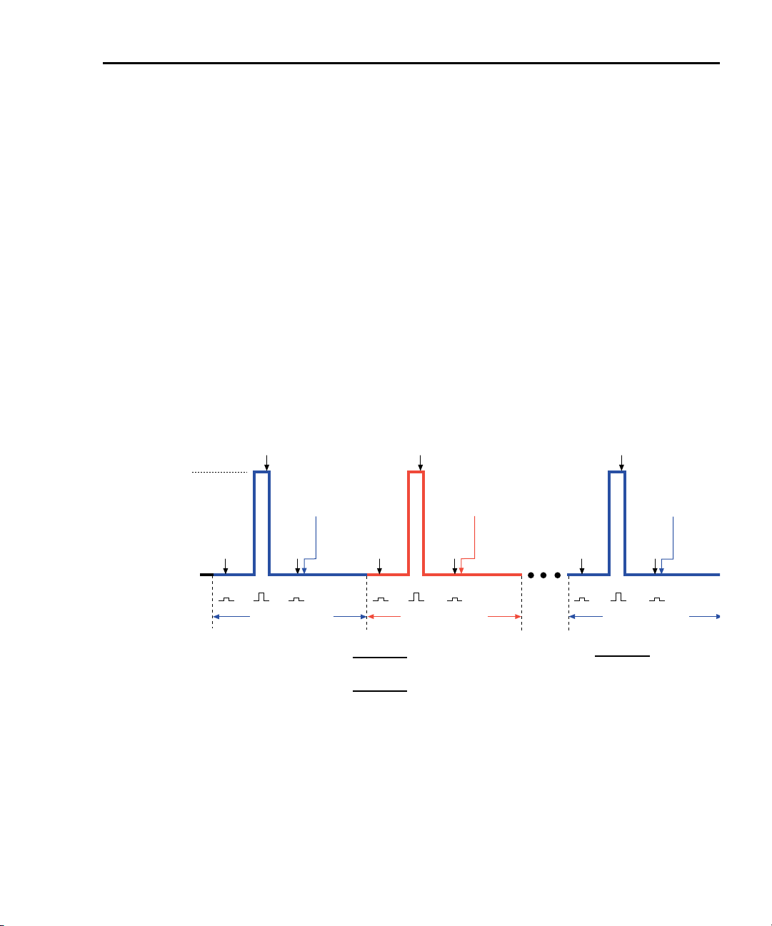
Model 6220/6221 User’s Manual Delta, Pulse Delta, and Differential Conductance 5-21
Pulse Delta
Use the Keithley Model 2182A with the Model 6221 to run Pulse Delta.
Model 6221 measurement process
Pulse Delta measurements
For Pulse Delta, the Model 6221 outputs current pulses. Current pulses that have
a short pulse width are ideal to test a low-power DUT that is heat sensitive.
By default, Pulse Delta uses a 3-point repeating-average algorithm to calculate
readings. Each Pulse Delta reading is calculated using A/D measurements for a
low pulse, a high pulse, and another low pulse. The Model 6221 outputs the
pulses, and the Model 2182A performs the A/D measurements. As shown in
Figure 5-7, every three pulses yields a single Pulse Delta voltage reading.
Figure 5-7
Pulse Delta 3-point measurement technique
2182A
I-High
62xx
I-Source
2182A
A/D
A
I-Low
1st Pulse Delta Reading =
2nd Pulse Delta Reading =
High
1st Pulse Delta
In cases where the high pulse will cause heating of the Device Under Test (DUT),
the measurement at the second low pulse could be adversely affected by the heat
caused by the high pulse. In that case, the measurement at the second low pulse
can be disabled. This does not change the overall timing of the pulse output. Eliminating the second low pulse measurement changes the basic calculation to the
following:
Pulse Delta = (2Y – 2X) / 2
2182A
A/D
D
2
2
2182A
A/D
E
Pulse Delta
Reading
2nd
2182A
A/D
F
2nd Pulse Delta
Interval
Nth Pulse Delta Reading =
)
Where:
X, Y, and Z are the A/Ds for the first low, high, and
)
second low pulses for the Pulse Delta cycle.
A/D
B
Pulse Delta
Reading
1st
2182A
A/D
C
LowLow High LowLow High LowLow
Interval
2B - A - C
(
2E - D - F
(
2182A
A/D
X
2Y - X - Z
(
2182A
A/D
Y
Pulse Delta
Reading
Nth
2182A
A/D
Z
Nth Pulse Delta
Interval
)
2
Return to Section 5 topics
Page 96

5-22 Delta, Pulse Delta, and Differential Conductance Model 6220/6221 User’s Manual
Where: Y is the measurement at the high pulse.
X is the measurement at the first low pulse.
Measurement units
The fundamental Pulse Delta measurement explained above is in volts. The reading can instead be converted into Ohms (W), Siemens (S), or Power (W). Details
on selecting “Measurement units” are provided on page 5-11.
Peak power and Average power
With Power units selected, a Pulse Delta reading can be expressed (and displayed) as a Peak power reading or an Average power reading. Peak power is the
default setting. See “Measurement units” in Section 5 of the Reference Manual for
details on Peak power and Average power for Pulse Delta.
Pulse Delta outputs
Pulse Delta output is made up of one or more Pulse Delta cycles. Each cycle is
made up of three output pulses (low, high, and low). The time period for a cycle is
adjustable and is the same for all cycles. The output pulses have an adjustable
pulse width, which is the same for all pulses.
There are two basic Pulse Delta output types: Fixed output and Sweep output. For
Fixed output, all high and low pulses are fixed for all Pulse Delta cycles in the test.
For Sweep output, the sweep (SWP) function of the Model 6221 is used to output
a staircased, logarithmic, or user-specified (custom) pulse sweep.
Fixed output
Figure 5-8 shows one Pulse Delta cycle for a Fixed output. As shown, the
Model 6221 outputs a low pulse, a high pulse, and then another low pulse during
every Pulse Delta cycle. The pulse width is adjustable and is the same for all high
and low pulses. The cycle interval is also adjustable and is based on the set number of power line cycles. The Pulse Delta interval shown in Figure 5-8 is set for 5
PLC (power line cycles), which is the default setting. After the set interval expires,
the next Pulse Delta cycle starts (if pulse count is >1).
Pulses are synchronized to the frequency of the power line voltage. When Pulse
Delta is started, the three pulses (low, high, and low) are generated on the
positive-going edges of the first three power line cycles. For the remaining power
line cycles in the interval, the output remains at the I-Low level.
Sweep output
The sweep feature of the Model 6221 can be used to output a series of pulses that
allow the use of different levels for the high pulses. Each high pulse returns to the
programmed low pulse level. The low level is the same for all pulses.
Return to Section 5 topics
Page 97

Model 6220/6221 User’s Manual Delta, Pulse Delta, and Differential Conductance 5-23
Like the Fixed output shown in Figure 5-8, a Sweep output is synchronized to the
frequency of the power line voltage, and the pulse width is adjustable and is the
same for all pulses.
The three available sweeps include (1) staircase sweep, (2) logarithmic sweep,
and (3) custom sweep. Examples of these Sweep outputs are shown in
Figure 5-9.
Staircase sweep – Figure 5-9A shows an example of a staircase Sweep out-
put. The sweep is configured to start high pulses at 2mA and staircase to
10mA in 2mA steps. The low pulse level for this sweep is 0mA.
Logarithmic sweep – Figure 5-9B shows an example of a logarithmic Sweep
output. The sweep is configured to output five high pulses (points). The first
high pulse starts at 1mA and logarithmically steps to 10mA. The low pulse
level for this sweep is 0mA.
Custom sweep – Figure 5-9C shows an example of a custom Sweep output.
The sweep is configured to output five high pulses (points). The level for each
high pulse is specified by the user. The high pulse levels for this output are
1mA, 2mA, 4mA, 8mA, and 16mA. The low pulse level for this sweep is 0mA.
Notice that the time period for each Pulse Delta cycle is determined by the set
sweep delay. The sweep (including sweep delay) is configured from the
CONFIGURE SWEEPS menu. See Section 4 for details.
Return to Section 5 topics
Page 98

5-24 Delta, Pulse Delta, and Differential Conductance Model 6220/6221 User’s Manual
Figure 5-8
Pulse timing
One Pulse Delta Cycle
(Interval = 5 PLC)
Pulse
3
Width
1
I-High
Pulse
3
Width
2
I-Low
Power
Line
Voltage
1. I-High can be set from -105mA to +105mA (default is 1mA).
2. I-Low can be set from -105mA to +105mA (default is 0mA).
3. Pulse Width can be set from 50µs to 12ms (default is 110µs).
4. One 60Hz power line cycle = 16.667ms (1/60)
5. With Interval set to 5 PLC (power line cycles):
60Hz: One Pulse Delta cycle = 83.33ms (5/60)
50Hz: One Pulse Delta cycle = 100ms (5/50)
6. Interval can be set from 5 to 999999 PLC (default is 5 PLC).
Low High Low
4
One Line Cycle
One 50Hz power line cylce = 20ms (1/50)
One Line Cycle
Pulse
Width
4
One Line Cycle4One Line Cycle4One Line Cycle
5, 6
3
4
Return to Section 5 topics
Page 99

Model 6220/6221 User’s Manual Delta, Pulse Delta, and Differential Conductance 5-25
Figure 5-9
Pulse sweep output examples
A) Staircase sweep pulse train: 2 to 10mA in 2mA steps
Linear
Scale
10mA
Stop
Start
2mA
Low
LO HI LO LO HI LO LO HI LO LO HI LO LO HI LO
0mA
One Pulse Delta Cycle
B) Logarithmic sweep pulse train: 1 to 10mA using 5 logarithmic
Logrithmic
Scale
10mA
Stop
Start
1mA
Low
LO HI LO
0mA
One Pulse Delta Cycle
Step = 2mA (set by the user)
4mA
2mA
(Sweep Delay)
Step
One Pulse Delta Cycle
(Sweep Delay)
Log Step is calculated and set by the 622x.
1.7783mA
1mA
(Sweep Delay)
Log Step
LO HI LO LO HI LO LO HI LO LO HI LO
One Pulse Delta Cycle
(Sweep Delay)
Step
Log Step
6mA
One Pulse Delta Cycle
(Sweep Delay)
3.1623mA
One Pulse Delta Cycle
(Sweep Delay)
Log Step
8mA
Step
One Pulse Delta Cycle
(Sweep Delay)
5.6234mA
One Pulse Delta Cycle
(Sweep Delay)
Step
Log Step
10mA
One Pulse Delta Cycle
(Sweep Delay)
10mA
One Pulse Delta Cycle
(Sweep Delay)
C) Custom sweep pulse train: 1mA, 2mA, 4mA, 8mA, and 16mA (5 points)
Linear
Scale
16mA
8mA
Low
0mA
1mA
LO HI LO LO HI LO LO HI LO LO HI LO LO HI LO
One Pulse Delta Cycle
(Sweep Delay)
2mA
One Pulse Delta Cycle
(Sweep Delay)
4mA
One Pulse Delta Cycle
(Sweep Delay)
One Pulse Delta Cycle
(Sweep Delay)
Return to Section 5 topics
16mA
One Pulse Delta Cycle
(Sweep Delay)
Page 100

5-26 Delta, Pulse Delta, and Differential Conductance Model 6220/6221 User’s Manual
Duty Cycle
Duty cycle defines the ratio between pulse “on” time and pulse “off” time during a
Pulse Delta cycle. For example, for a 25% duty cycle, the pulse would be “on”
(high) for one-quarter of the cycle, and “off” (0mA low) for three-quarters of the
cycle. Pulse Delta cycles with a short duty-cycle can be sourced to prevent heat
from adversely affecting the measurement of low power DUT.
When using a 0mA low level (which is the default), the duty cycle for the Pulse
Delta cycle is calculated as follows:
PulseWidth
DutyCycle
Where: DutyCycle = Duty cycle expressed as a percent.
Pulse Delta cycle time period
Sweep output – The time period for each Pulse Delta cycle is the same as the
sweep delay time that is set by the user when configuring the sweep.
Fixed output – The Pulse Delta cycle (interval) is expressed as the number of
power line cycles (PLC). This PLC value must be converted into time (seconds) as
follows:
For 60Hz line power:
Pulse Delta cycle time period = Interval setting (PLC) x 16.667ms
-------------------------------------------------
PulseDeltaCycle
PulseWidth = User specified Pulse Width (in seconds).
PulseDeltaCycle = Time period (in seconds) for each Pulse Delta cycle
(see “Pulse Delta cycle time period”).
100•=
For 50Hz line power:
Pulse Delta cycle time period = Interval setting (PLC) x 20ms
Example – For 60Hz line power, the Pulse Delta cycle time period for an Interval
setting of 5 PLC is calculated as follows:
Pulse Delta cycle time period = 5 x 16.667ms
Configuration settings
Pulse Delta settings from the front panel are described as follows. These parameters are set from the CONFIG PULSE DELTA menu that is accessed by pressing
the CONFIG key and then the PULSE key.
The equivalent remote programming commands to configure Pulse Delta are
summarized in Table 5-3.
= 83.33ms
Return to Section 5 topics
 Loading...