

Page 1

Test Equipment Depot - 800.517.8431 - 99 Washington Street Melrose, MA 02176 - TestEquipmentDepot.com
Model 2400 Series SourceMeter
User's Manual
®
A GREATER MEASURE OF CONFIDENCE
Page 2

WARRANTY
Keithley Instruments, Inc. warrants this product to be free from defects in material and w
orkmanship for a
period of 1 year from date of shipment.
Keithley Instruments, Inc. warrants the following items for 90 days from the date of shipment: probes, cables,
rechargeable batteries, diskettes, and documentation.
During the warranty period, we will, at our option, either repair or replace any product that proves to be defective.
To exercise this warranty, write or call your local Keithley representative, or contact Keithley headquarters in
Cleveland, Ohio. You will be given prompt assistance and return instructions. Send the product, transportation
prepaid, to the indicated service facility. Repairs will be made and the product returned, transportation prepaid.
Repaired or replaced products are warranted for the balance of the original warranty period, or at least 90 days.
LIMITATION OF W
This warranty does not apply to defects resulting from product modification without Keithle
ARRANTY
y’s express written
consent, or misuse of any product or part. This warranty also does not apply to fuses, software, non-rechargeable
batteries, damage from battery leakage, or problems arising from normal wear or failure to follow instructions.
THIS WARRANTY IS IN LIEU OF ALL OTHER WARRANTIES, EXPRESSED OR IMPLIED, INCLUDING ANY IMPLIED WARRANTY OF MERCHANTABILITY OR FITNESS FOR A PARTICULAR USE.
THE REMEDIES PROVIDED HEREIN ARE BUYER’S SOLE AND EXCLUSIVE REMEDIES.
NEITHER KEITHLEY INSTRUMENTS, INC. NOR ANY OF ITS EMPLOYEES SHALL BE LIABLE FOR
ANY DIRECT, INDIRECT, SPECIAL, INCIDENTAL OR CONSEQUENTIAL DAMAGES ARISING OUT OF
THE USE OF ITS INSTRUMENTS AND SOFTWARE EVEN IF KEITHLEY INSTRUMENTS, INC., HAS
BEEN ADVISED IN ADVANCE OF THE POSSIBILITY OF SUCH DAMAGES. SUCH EXCLUDED DAMAGES SHALL INCLUDE, BUT ARE NOT LIMITED TO: COSTS OF REMOVAL AND INSTALLATION,
LOSSES SUSTAINED AS THE RESULT OF INJURY TO ANY PERSON, OR DAMAGE TO PROPERTY.
Keithley Instruments, Inc.
Sales Of
fices: BELGIUM:
CHINA: Yuan Chen Xin Building, Room 705 • 12 Yumin Road, Dewai, Madian • Beijing 100029 • 8610-6202-2886 • Fax: 8610-6202-2892
FINLAND: Tietäjäntie 2 • 02130 Espoo • Phone: 09-54 75 08 10 • Fax: 09-25 10 51 00
FRANCE: 3, allée des Garays • 91127 Palaiseau Cédex • 01-64 53 20 20 • Fax: 01-60 11 77 26
GERMANY: Landsberger Strasse 65 • 82110 Germering • 089/84 93 07-40 • Fax: 089/84 93 07-34
GREAT BRITAIN: Unit 2 Commerce Park, Brunel Road • Theale • Berkshire RG7 4AB • 0118 929 7500 • Fax: 0118 929 7519
INDIA: Flat 2B, Willocrissa • 14, Rest House Crescent • Bangalore 560 001 • 91-80-509-1320/21 • Fax: 91-80-509-1322
ITALY: Viale San Gimignano, 38 • 20146 Milano • 02-48 39 16 01 • Fax: 02-48 30 22 74
JAPAN: New Pier Takeshiba North Tower 13F • 11-1, Kaigan 1-chome • Minato-ku, Tokyo 105-0022 • 81-3-5733-7555 • Fax: 81-3-5733-7556
KOREA: 2FL., URI Building • 2-14 Yangjae-Dong • Seocho-Gu, Seoul 137-888 • 82-2-574-7778 • Fax: 82-2-574-7838
NETHERLANDS: Postbus 559 • 4200 AN Gorinchem • 0183-635333 • Fax: 0183-630821
SWEDEN: c/o Regus Business Centre • Frosundaviks Allé 15, 4tr • 169 70 Solna • 08-509 04 679 • Fax: 08-655 26 10
SWITZERLAND: Kriesbachstrasse 4 • 8600 Dübendorf • 01-821 94 44 • Fax: 01-820 30 81
TAIWAN: 1FL., 85 Po Ai Street • Hsinchu, Taiwan, R.O.C. • 886-3-572-9077• Fax: 886-3-572-9031
Bergensesteenweg 709 • B-1600 Sint-Pieters-Leeuw • 02-363 00 40 • Fax: 02/363 00 64
4/02
Page 3

2400 Series SourceMeter
User’s Manual
®
©1998, Keithley Instruments, Inc.
All rights reserved.
Cleveland, Ohio, U.S.A.
Seventh Printing, May 2002
Document Number: 2400S-900-01 Rev. G
Page 4

Manual Print History
The print history shown below lists the printing dates of all Revisions and Addenda created
for this manual. The Revision Level letter increases alphabetically as the manual undergoes subsequent updates. Addenda, which are released between Revisions, contain important change information that the user should incorporate immediately into the manual. Addenda are numbered
sequentially. When a new Revision is created, all Addenda associated with the previous Revision
of the manual are incorporated into the new Revision of the manual. Each new Revision includes
a revised copy of this print history page.
Revision A (Document Number 2400S-900-01)........................................................... August 1998
Revision B (Document Number 2400S-900-01).......................................................... January 1999
Addendum B (Document Number 2400S-900-02) ..........................................................April 1999
Revision C (Document Number 2400S-900-01).............................................................. April 1999
Addendum C (Document Number 2400S-900-02) ..................................................November 1999
Revision D (Document Number 2400S-900-01).......................................................... January 2000
Revision E (Document Number 2400S-900-01) ................................................................ July 2000
Revision F (Document Number 2400S-900-01) ...............................................................June 2001
Revision G (Document Number 2400S-900-01)............................................................... May 2002
All Keithley product names are trademarks or registered trademarks of Keithley Instruments, Inc.
Other brand names are trademarks or registered trademarks of their respective holders.
Page 5

S
afety Precautions
The following safety precautions should be observed before using this product and any associated instrumentation. Although
some instruments and accessories would normally be used with non-hazardous voltages, there are situations where hazardous
conditions may be present.
This product is intended for use by qualified personnel who recognize shock hazards and are familiar with the safety precautions
required to avoid possible injury. Read and follow all installation, operation, and maintenance information carefully before using the product. Refer to the manual for complete product specifications.
If the product is used in a manner not specified, the protection provided by the product may be impaired.
The types of product users are:
Responsible body
ment is operated within its specifications and operating limits, and for ensuring that operators are adequately trained.
Operators
instrument. They must be protected from electric shock and contact with hazardous live circuits.
Maintenance personnel
voltage or replacing consumable materials. Maintenance procedures are described in the manual. The procedures explicitly state
if the operator may perform them. Otherwise, they should be performed only by service personnel.
Service personnel
trained service personnel may perform installation and service procedures.
Keithley products are designed for use with electrical signals that are rated Installation Category I and Installation Category II,
as described in the International Electrotechnical Commission (IEC) Standard IEC 60664. Most measurement, control, and data
I/O signals are Installation Category I and must not be directly connected to mains voltage or to voltage sources with high transient over-voltages. Installation Category II connections require protection for high transient over-voltages often associated with
local AC mains connections. Assume all measurement, control, and data I/O connections are for connection to Category I sources unless otherwise marked or described in the Manual.
Exercise extreme caution when a shock hazard is present. Lethal voltage may be present on cable connector jacks or test fixtures.
The American National Standards Institute (ANSI) states that a shock hazard exists when voltage levels greater than 30V RMS,
42.4V peak, or 60VDC are present.
circuit before measuring.
Operators of this product must be protected from electric shock at all times. The responsible body must ensure that operators
are prevented access and/or insulated from every connection point. In some cases, connections must be exposed to potential
human contact. Product operators in these circumstances must be trained to protect themselves from the risk of electric shock.
If the circuit is capable of operating at or above 1000 volts,
Do not connect switching cards directly to unlimited power circuits. They are intended to be used with impedance limited sources. NEVER connect switching cards directly to AC mains. When connecting sources to switching cards, install protective devices to limit fault current and voltage to the card.
Before operating an instrument, make sure the line cord is connected to a properly grounded power receptacle. Inspect the connecting cables, test leads, and jumpers for possible wear, cracks, or breaks before each use.
When installing equipment where access to the main power cord is restricted, such as rack mounting, a separate main input power disconnect device must be provided, in close proximity to the equipment and within easy reach of the operator.
For maximum safety, do not touch the product, test cables, or any other instruments while power is applied to the circuit under
test. ALWAYS remove power from the entire test system and discharge any capacitors before: connecting or disconnecting ca-
is the individual or group responsible for the use and maintenance of equipment, for ensuring that the equip-
use the product for its intended function. They must be trained in electrical safety procedures and proper use of the
perform routine procedures on the product to keep it operating properly, for example, setting the line
are trained to work on live circuits, and perform safe installations and repairs of products. Only properly
A good safety practice is to expect that hazardous voltage is present in any unknown
no conductive part of the circuit may be exposed.
5/02
Page 6

bles or jumpers, installing or removing switching cards, or making internal changes, such as installing or removing jumpers.
Do not touch any object that could provide a current path to the common side of the circuit under test or power line (earth) ground. Al-
ways make measurements with dry hands while standing on a dry, insulated surface capable of withstanding the voltage being measured.
The instrument and accessories must be used in accordance with its specifications and operating instructions or the safety of the
equipment may be impaired.
Do not exceed the maximum signal levels of the instruments and accessories, as defined in the specifications and operating in-
formation, and as shown on the instrument or test fixture panels, or switching card.
When fuses are used in a product, replace with same type and rating for continued protection against fire hazard.
Chassis connections must only be used as shield connections for measuring circuits, NOT as safety earth ground connections.
If you are using a test fixture, keep the lid closed while power is applied to the device under test. Safe operation requires the use
of a lid interlock.
If or is present, connect it to safety earth ground using the wire recommended in the user documentation.
!
The symbol on an instrument indicates that the user should refer to the operating instructions located in the manual.
The symbol on an instrument shows that it can source or measure 1000 volts or more, including the combined effect of
normal and common mode voltages. Use standard safety precautions to avoid personal contact with these voltages.
The
WARNING
information very carefully before performing the indicated procedure.
The
CAUTION
ranty.
Instrumentation and accessories shall not be connected to humans.
Before performing any maintenance, disconnect the line cord and all test cables.
To maintain protection from electric shock and fire, replacement components in mains circuits, including the power transformer,
test leads, and input jacks, must be purchased from Keithley Instruments. Standard fuses, with applicable national safety approvals, may be used if the rating and type are the same. Other components that are not safety related may be purchased from
other suppliers as long as they are equivalent to the original component. (Note that selected parts should be purchased only
through Keithley Instruments to maintain accuracy and functionality of the product.) If you are unsure about the applicability
of a replacement component, call a Keithley Instruments office for information.
To clean an instrument, use a damp cloth or mild, water based cleaner. Clean the exterior of the instrument only. Do not apply
cleaner directly to the instrument or allow liquids to enter or spill on the instrument. Products that consist of a circuit board with
no case or chassis (e.g., data acquisition board for installation into a computer) should never require cleaning if handled according to instructions. If the board becomes contaminated and operation is affected, the board should be returned to the factory for
proper cleaning/servicing.
heading in a manual explains dangers that might result in personal injury or death. Always read the associated
heading in a manual explains hazards that could damage the instrument. Such damage may invalidate the war-
Page 7

Table of Contents
1 Getting Started
General information ................................................................... 1-2
Warranty information .......................................................... 1-2
Contact information ............................................................ 1-2
Manual addenda .................................................................. 1-2
Safety symbols and terms ................................................... 1-2
Inspection ............................................................................ 1-3
Options and accessories ...................................................... 1-3
Product overview ........................................................................ 1-5
Front and rear panel familiarization ........................................... 1-7
Front panel summary .......................................................... 1-7
Rear panel summary ........................................................... 1-9
Power-up .................................................................................. 1-10
Line power connection ...................................................... 1-10
Power-up sequence ........................................................... 1-11
System identification ......................................................... 1-11
Line frequency setting ....................................................... 1-12
Fuse replacement .............................................................. 1-13
Cooling fan ............................................................................... 1-13
Display ..................................................................................... 1-14
Display format .................................................................. 1-14
EDIT key ........................................................................... 1-14
TOGGLE key .................................................................... 1-15
Status and error messages ................................................. 1-15
Remote display programming ........................................... 1-15
Front panel tests ................................................................ 1-16
Default settings ......................................................................... 1-16
Saving and restoring user setups ....................................... 1-16
Factory default settings ..................................................... 1-17
Remote setups ................................................................... 1-20
General purpose probes ............................................... 1-3
Low thermal probes ..................................................... 1-4
Cables and adapters ..................................................... 1-4
Rack mount kits ........................................................... 1-5
Carrying case ............................................................... 1-5
Front panel line frequency ......................................... 1-12
Remote command line frequency .............................. 1-12
Saving setups ............................................................. 1-16
Restoring setups ......................................................... 1-16
Power-on configuration .............................................. 1-17
Page 8

Menus ....................................................................................... 1-20
Main menu ......................................................................... 1-20
Rules to navigate menus .................................................... 1-24
Editing source and compliance values .............................. 1-24
Toggling the source and measure display fields ................ 1-25
Disabling front panel display ............................................ 1-25
Front panel control ..................................................... 1-26
Remote command programming ................................ 1-26
Configuration menus ......................................................... 1-26
2 Connections
Connection overview .................................................................. 2-2
Front/rear terminals selection .............................................. 2-2
Front panel terminals selection .................................... 2-2
Remote command terminals selection ......................... 2-3
Test fixture interlock .................................................... 2-3
Connections to DUT ................................................................... 2-3
Sensing methods .................................................................. 2-5
4-wire remote sensing .................................................. 2-6
2-wire local sensing ..................................................... 2-7
Guarding methods ............................................................... 2-8
Cable guard .................................................................. 2-8
Ohms guard .................................................................. 2-9
Sense and guard selections ......................................... 2-11
Sense selection ........................................................... 2-11
Guard selection .......................................................... 2-12
3 Basic Source-Measure Operation
WARNING - CAUTION ............................................................ 3-2
Operation overview .................................................................... 3-3
Source-measure capabilities ................................................ 3-3
Compliance limit ................................................................. 3-6
Setting the compliance limit ................................................ 3-7
Front panel compliance limit ....................................... 3-7
Compliance range synchronization .............................. 3-7
Remote compliance limit ............................................. 3-7
Basic circuit configurations ................................................. 3-8
Operation considerations ............................................................ 3-9
Warm-up .............................................................................. 3-9
Auto zero ............................................................................. 3-9
Front panel auto zero .................................................... 3-9
Remote command auto zero ......................................... 3-9
Page 9

NPLC caching ................................................................... 3-10
NPLC cache setup ...................................................... 3-10
Typical NPLC cache test times .................................. 3-11
V-source protection ........................................................... 3-11
Front panel V-source protection ................................. 3-12
Remote command V-source protection ...................... 3-12
Source delay ...................................................................... 3-12
Front panel source delay ............................................ 3-13
Remote command source delay ................................. 3-13
Basic source-measure procedure .............................................. 3-14
Output control ................................................................... 3-14
Front panel source-measure procedure ............................. 3-14
Step 1: Select source. ................................................. 3-14
Step 2: Set source level and compliance limit. .......... 3-14
Step 3: Select measurement function and range. ....... 3-16
Step 4: Turn output on. .............................................. 3-17
Step 5: Observe readings on the display. ................... 3-17
Step 6: Turn output off. .............................................. 3-18
Remote command source-measure procedure .................. 3-18
Basic source-measure commands .............................. 3-18
Source-measure programming example .................... 3-19
Measure only ............................................................................ 3-20
Front panel measure only .................................................. 3-20
Remote command measure only ....................................... 3-21
Sink operation .......................................................................... 3-22
Battery charging/discharging ............................................ 3-22
Sink programming example .............................................. 3-24
4 Ohms Measurements
Ohms configuration menu .......................................................... 4-2
Ohms measurement methods ..................................................... 4-3
Selecting ohms measurement method ................................. 4-4
Auto ohms measurements ................................................... 4-4
Manual ohms measurements ............................................... 4-5
Ohms sensing ............................................................................. 4-7
Sense selection .................................................................... 4-8
Offset-compensated ohms .......................................................... 4-9
Enabling/disabling offset-compensated ohms .................... 4-9
Offset-compensated ohms procedure ................................ 4-10
Ohms source readback ............................................................. 4-11
Ohms source readback selection ....................................... 4-11
6-wire ohms measurements ...................................................... 4-11
Remote ohms programming ..................................................... 4-12
Remote ohms commands .................................................. 4-12
Ohms programming example ............................................ 4-13
Page 10

5 Pulse Mode Operation (Model 2430 only)
Overview .................................................................................... 5-2
Pulse characteristics .................................................................... 5-3
Pulse width .......................................................................... 5-4
Signal measurement ..................................................... 5-4
Overhead time .............................................................. 5-4
Pulse width delay ......................................................... 5-5
Output off-time .................................................................... 5-5
Reference and zero measurements ............................... 5-5
Overhead time .............................................................. 5-5
Pulse delay ................................................................... 5-6
Pulse duty cycle ................................................................... 5-6
Fast pulse output .................................................................. 5-6
Auto zero ...................................................................... 5-7
Pulse-only ..................................................................... 5-8
Pulse jitter ............................................................................ 5-8
Pulse energy limitations (10A range) ......................................... 5-9
Pulse Mode configuration ......................................................... 5-10
Front panel Pulse Mode configuration .............................. 5-10
Select Pulse Mode, and set pulse width
and pulse delay ....................................................... 5-10
Set pulse measurement speed ..................................... 5-10
Set pulse count ........................................................... 5-10
Disable/enable auto zero ............................................ 5-11
Remote command Pulse Mode configuration ................... 5-11
Basic Pulse Mode operation ..................................................... 5-12
Front panel pulse-measure procedure ............................... 5-12
Step 1: Select Pulse Mode, and set pulse width
and pulse delay. ...................................................... 5-12
Step 2: Set pulse measurement speed. ....................... 5-12
Step 3: Set pulse count. .............................................. 5-12
Step 4: Select source. ................................................. 5-13
Step 5: Set pulse level and compliance limit. ............. 5-13
Step 6: Select measurement function and range. ....... 5-13
Step 7: Turn output on. ............................................... 5-14
Pulse-ohms measurements ................................................ 5-14
Auto and Manual pulse-ohms measurements ............ 5-14
Offset-compensated pulse-ohms measurements ........ 5-14
Remote command pulse-measure operation ..................... 5-15
Basic pulse commands ............................................... 5-15
Ignored settings and invalid commands ..................... 5-15
Pulse-measure programming example ....................... 5-16
Page 11

Pulse-measure considerations .................................................. 5-16
Measurement speed ........................................................... 5-16
Filter .................................................................................. 5-17
Auto range ......................................................................... 5-17
Concurrent measurements ................................................. 5-17
Ohms source readback ...................................................... 5-17
Toggle key ......................................................................... 5-17
Offset-compensated ohms ................................................. 5-18
Source delay ...................................................................... 5-18
Trigger delay ..................................................................... 5-18
Input triggers ..................................................................... 5-19
Output triggers .................................................................. 5-19
Auto output-off ................................................................. 5-19
Output-off state ................................................................. 5-19
Turning source on ............................................................. 5-20
SCPI signal oriented measurement commands ................. 5-20
6 Source-Measure Concepts
Compliance limit ........................................................................ 6-2
Types of compliance ........................................................... 6-2
Maximum compliance values ............................................. 6-3
Compliance examples ......................................................... 6-4
Compliance principles ........................................................ 6-4
Passive load compliance example ................................ 6-4
Active load compliance example ................................. 6-4
Determining compliance limit ............................................ 6-5
Overheating protection ............................................................... 6-6
Overheating conditions ....................................................... 6-6
Power equations to avoid shutdown .................................... 6-7
Model 2400 SourceMeter ............................................ 6-7
Model 2410 SourceMeter ............................................ 6-8
Model 2420 SourceMeter ............................................ 6-8
Models 2425 and 2430 SourceMeters ......................... 6-9
Model 2440 SourceMeter ............................................ 6-9
Source-delay-measure cycle ..................................................... 6-10
Sweep waveforms ............................................................. 6-12
Operating boundaries ............................................................... 6-14
Source or sink ................................................................... 6-14
Duty cycle ......................................................................... 6-14
Model 2400 SourceMeter .......................................... 6-15
Model 2410 SourceMeter .......................................... 6-16
Model 2420 SourceMeter .......................................... 6-17
Models 2425 and 2430 SourceMeters ....................... 6-18
Model 2440 SourceMeter .......................................... 6-20
Page 12

I-Source operating boundaries .......................................... 6-21
Voltage compliance boundaries .................................. 6-24
V-Source operating boundaries ......................................... 6-26
Current compliance boundaries ................................. 6-28
Source I measure I and source V measure V ..................... 6-30
Source readback accuracy .......................................... 6-30
Basic circuit configurations ...................................................... 6-31
Source I ............................................................................. 6-31
Source V ............................................................................ 6-32
Measure only (V or I) ........................................................ 6-33
Guard ........................................................................................ 6-34
Cable guard ....................................................................... 6-34
Ohms guard ....................................................................... 6-35
Guard sense ....................................................................... 6-38
Data flow ................................................................................... 6-40
Buffer considerations ........................................................ 6-42
Changing V, I, or Ω measurement function ................ 6-42
Changing MATH function ......................................... 6-43
Changing REL or LIMITS ......................................... 6-43
7 Range, Digits, Speed, and Filters
Range and digits ......................................................................... 7-2
Range ................................................................................... 7-2
Maximum readings ...................................................... 7-2
Ranging limitations ...................................................... 7-2
Manual ranging ............................................................ 7-3
Auto ranging ................................................................ 7-3
Auto range considerations ............................................ 7-3
Auto range change mode .............................................. 7-4
Auto range limits .......................................................... 7-4
Limits evaluation .......................................................... 7-5
Digits ................................................................................... 7-5
Setting display resolution ............................................. 7-5
Remote range and digits programming ............................... 7-5
Range and digits commands ........................................ 7-6
Range and digits programming example ...................... 7-6
Speed .......................................................................................... 7-7
Setting speed ....................................................................... 7-7
Front panel speed control ............................................. 7-7
PULSE SPEED (NPLC) – Model 2430 Pulse Mode ... 7-8
Remote speed programming ................................................ 7-8
Speed commands .......................................................... 7-8
Speed programming example ....................................... 7-9
Page 13

Filters ......................................................................................... 7-9
Response time considerations ...................................... 7-9
Front panel filter control ................................................... 7-10
Configuring filter ....................................................... 7-10
CONFIGURE FILTERING menu ............................. 7-10
Enabling filter ............................................................ 7-10
Response time ............................................................ 7-11
Remote filter programming ............................................... 7-12
Filter commands ........................................................ 7-12
Filter programming example ..................................... 7-13
8 Relative and Math
Relative ....................................................................................... 8-2
Front panel rel ..................................................................... 8-2
Enabling and disabling rel ........................................... 8-2
Defining a rel value ...................................................... 8-2
Remote rel programming .................................................... 8-3
Rel commands ............................................................. 8-3
Rel programming example .......................................... 8-3
Math operations .......................................................................... 8-4
Built-in math functions ....................................................... 8-4
Power ........................................................................... 8-4
Offset-compensated ohms ............................................ 8-4
Varistor alpha ............................................................... 8-5
Voltage coefficient ....................................................... 8-5
Percent deviation .......................................................... 8-6
Front panel math operations ................................................ 8-6
Remote math operations ..................................................... 8-7
Math commands ........................................................... 8-7
Math programming example ........................................ 8-8
User-defined math functions ............................................... 8-9
Commands for user-defined math functions ................ 8-9
User-defined math function programming example .. 8-10
9 Data Store
Data store overview .................................................................... 9-2
Front panel data store ................................................................. 9-2
Storing readings .................................................................. 9-2
Recalling readings ............................................................... 9-2
Buffer location number ................................................ 9-2
Timestamp ................................................................... 9-3
Displaying other buffer readings ................................. 9-3
Page 14

Buffer statistics .................................................................... 9-3
Minimum and maximum .............................................. 9-3
Peak-to-peak ................................................................. 9-3
Average ......................................................................... 9-4
Standard deviation ........................................................ 9-4
Timestamp format ............................................................... 9-4
Timestamp accuracy ............................................................ 9-5
Buffer considerations .......................................................... 9-5
Using :TRACe commands to store data ....................... 9-5
Using :READ? to store data ......................................... 9-5
Remote command data store ...................................................... 9-6
Data store commands .......................................................... 9-6
Data store programming example ....................................... 9-7
10 Sweep Operation
Sweep types .............................................................................. 10-2
Linear staircase sweep ....................................................... 10-2
Logarithmic staircase sweep ............................................. 10-4
Custom sweep ................................................................... 10-5
Custom sweep examples ............................................ 10-6
Source memory sweep ...................................................... 10-7
Sweep configuration ................................................... 10-7
Saving and restoring source memory setups .............. 10-7
Saving multiple source memory sweeps .................... 10-8
Saved source memory configurations ........................ 10-8
Sweep branching ...................................................... 10-10
Diode test example ................................................... 10-12
Configuring and running a sweep ........................................... 10-14
Front panel sweep operation ........................................... 10-14
Sweep configuration menu ....................................... 10-14
Setting delay ............................................................. 10-16
Trigger count and sweep points ............................... 10-16
Performing sweeps ................................................... 10-16
Performing a linear staircase sweep ......................... 10-17
Performing a log staircase sweep ............................. 10-18
Performing a custom sweep ..................................... 10-19
Performing a source memory sweep ........................ 10-21
Remote sweep operation ................................................. 10-22
Staircase sweep commands ...................................... 10-22
Staircase sweep programming example ................... 10-22
Custom sweep commands ........................................ 10-24
Custom sweep programming example ..................... 10-25
Source memory sweep commands ........................... 10-25
Source memory sweep programming example ........ 10-26
Page 15

Sweep branching program example ....................................... 10-27
Pulse Mode sweeps (Model 2430 only) ................................. 10-32
Front panel Pulse Mode sweep procedure ...................... 10-33
Remote Pulse Mode sweep operation ............................. 10-34
11 Triggering
Front panel trigger operation .................................................... 11-2
Front panel trigger model .................................................. 11-2
Event detection .......................................................... 11-2
Idle ............................................................................. 11-2
Arm layer ................................................................... 11-4
Trigger layer .............................................................. 11-5
Counters ..................................................................... 11-6
Output triggers ........................................................... 11-6
Bench defaults ........................................................... 11-7
Operation summary ................................................... 11-7
Configuring triggering ...................................................... 11-8
Trigger configuration menu ....................................... 11-8
Remote trigger operation ....................................................... 11-11
Remote trigger model ..................................................... 11-11
Idle and initiate ........................................................ 11-11
Event detection ........................................................ 11-13
Arm layer ................................................................. 11-13
Trigger layer ............................................................ 11-14
Counters ................................................................... 11-16
Output triggers ......................................................... 11-16
GPIB defaults ........................................................... 11-17
Operation summary ................................................. 11-17
Remote trigger commands .............................................. 11-18
Trigger link ............................................................................. 11-19
Input trigger requirements ............................................... 11-19
Output trigger specifications ........................................... 11-20
Triggering examples ............................................................... 11-20
Front panel trigger example ............................................ 11-20
External trigger example ................................................. 11-23
Trigger link connections .......................................... 11-24
Instrument configurations ........................................ 11-25
Operation ................................................................. 11-26
Remote trigger example .................................................. 11-28
Page 16

Pulse Mode triggering (Model 2430) ..................................... 11-30
Trigger models ................................................................ 11-30
Idle ........................................................................... 11-33
Source event detector ............................................... 11-33
Pulse delay ............................................................... 11-33
Source action ............................................................ 11-33
Pulse width ............................................................... 11-33
Measure action ......................................................... 11-33
Output triggers ......................................................... 11-34
Invalid trigger settings ..................................................... 11-34
Front panel operation ............................................... 11-34
Remote operation ..................................................... 11-34
12 Limit Testing
Types of limits .......................................................................... 12-2
Pass/fail information .......................................................... 12-3
Data flow ........................................................................... 12-3
Limit 1 test (compliance) .................................................. 12-3
Limit 2, limit 3, and limit 5-12 tests .................................. 12-4
Limit test modes ................................................................ 12-4
Binning .............................................................................. 12-4
Operation overview .................................................................. 12-5
Grading mode .................................................................... 12-5
Binning control .......................................................... 12-5
Pass condition ............................................................. 12-8
Fail condition ............................................................. 12-8
Sorting mode ..................................................................... 12-9
Binning ....................................................................... 12-9
Binning systems ...................................................................... 12-11
Handler interface ............................................................. 12-11
Digital I/O connector ............................................... 12-11
Digital output lines ................................................... 12-12
SOT line ................................................................... 12-12
/INT line ................................................................... 12-12
Handler types ................................................................... 12-12
Category pulse component handler .......................... 12-13
Category register component handler ...................... 12-13
Basic binning systems ..................................................... 12-14
Single-element device binning ................................. 12-14
Multiple-element device binning ............................. 12-15
Digital output clear pattern .............................................. 12-17
Enabling auto-clear .................................................. 12-17
Auto-clear timing ..................................................... 12-18
Page 17

Configuring and performing limit tests .................................. 12-19
Configuring limit tests ..................................................... 12-19
Performing front panel limit tests ................................... 12-21
Step 1: Configure test system. ................................. 12-21
Step 2: Configure source-measure functions. .......... 12-21
Step 3: Configure limit tests. ................................... 12-22
Step 4: Turn output on. ............................................ 12-22
Step 5: Start testing process. .................................... 12-22
Step 6: Stop testing process. .................................... 12-22
Remote limit testing ............................................................... 12-23
Limit commands ............................................................. 12-23
Limit test programming example .................................... 12-24
13 Digital I/O Port, Safety Interlock, and Output Configuration
Digital I/O port ......................................................................... 13-2
Port configuration .............................................................. 13-2
Digital output lines .................................................... 13-2
SOT line ..................................................................... 13-3
Interlock line .............................................................. 13-3
+5V output ................................................................. 13-3
Digital output configuration .............................................. 13-3
Sink operation ............................................................ 13-3
Source operation ........................................................ 13-4
Controlling digital output lines ......................................... 13-4
Front panel digital output control .............................. 13-4
Remote digital output control .................................... 13-5
Safety interlock ........................................................................ 13-5
Front panel output configuration .............................................. 13-7
Configure OUTPUT menu ................................................ 13-7
Output-off states ................................................................ 13-8
HIGH IMPEDANCE ................................................. 13-8
NORMAL .................................................................. 13-8
ZERO ......................................................................... 13-9
GUARD ..................................................................... 13-9
Output-off states and inductive loads .............................. 13-10
Remote output configuration .................................................. 13-11
Output configuration commands ..................................... 13-11
Output configuration programming example .................. 13-12
Page 18

14 Remote Operations
Differences: remote vs. local operation .................................... 14-2
Operation enhancements (remote operation) .................... 14-2
Math expressions ........................................................ 14-2
Concurrent measurements .......................................... 14-2
Local-to-remote transition ................................................. 14-2
Remote-to-local transition ................................................. 14-3
Selecting an interface ............................................................... 14-3
GPIB operation ......................................................................... 14-4
GPIB standards .................................................................. 14-4
GPIB connections .............................................................. 14-4
Primary address ................................................................. 14-6
General bus commands ............................................................. 14-7
REN (remote enable) ......................................................... 14-7
IFC (interface clear) .......................................................... 14-7
LLO (local lockout) ........................................................... 14-8
GTL (go to local) ............................................................... 14-8
DCL (device clear) ............................................................ 14-8
SDC (selective device clear) .............................................. 14-8
GET (group execute trigger) ............................................. 14-8
SPE, SPD (serial polling) .................................................. 14-9
Front panel GPIB operation ...................................................... 14-9
Error and status messages ................................................. 14-9
GPIB status indicators ....................................................... 14-9
REM ........................................................................... 14-9
TALK ....................................................................... 14-10
LSTN ........................................................................ 14-10
SRQ .......................................................................... 14-10
LOCAL key ..................................................................... 14-10
Programming syntax ............................................................... 14-11
Command words ............................................................. 14-11
Commands and command parameters ..................... 14-11
Query commands ............................................................. 14-13
Case sensitivity ................................................................ 14-13
Long-form and short-form versions ................................ 14-14
Short-form rules .............................................................. 14-14
Program messages ........................................................... 14-15
Single command messages ....................................... 14-15
Multiple command messages ................................... 14-15
Command path rules ................................................ 14-16
Using common and SCPI commands in the
same message ....................................................... 14-16
Program message terminator (PMT) ........................ 14-16
Command execution rules ........................................ 14-16
Page 19

Response messages ......................................................... 14-17
Sending a response message .................................... 14-17
Multiple response messages .................................... 14-17
Response message terminator (RMT) ..................... 14-17
Message exchange protocol ............................................ 14-17
RS-232 interface operation .................................................... 14-18
Sending and receiving data ............................................. 14-18
Baud rate ......................................................................... 14-18
Data bits and parity ......................................................... 14-18
Terminator ....................................................................... 14-19
Flow control (signal handshaking) .................................. 14-19
RS-232 connections ........................................................ 14-19
Error messages ................................................................ 14-21
Programming example .................................................... 14-21
15 Status Structure
Overview .................................................................................. 15-2
Status byte and SRQ ......................................................... 15-2
Status register sets ............................................................. 15-2
Queues ............................................................................... 15-2
Clearing registers and queues ................................................... 15-4
Programming and reading registers ......................................... 15-5
Programming enable registers ........................................... 15-5
Reading registers ............................................................... 15-6
Status byte and service request (SRQ) ..................................... 15-7
Status byte register ............................................................ 15-8
Service request enable register .......................................... 15-9
Serial polling and SRQ ..................................................... 15-9
SPE, SPD (serial polling) .......................................... 15-9
Status byte and service request commands ..................... 15-10
Programming example – set MSS (B6)
when error occurs ................................................ 15-10
Status register sets .................................................................. 15-11
Register bit descriptions .................................................. 15-11
Standard Event Register ........................................... 15-11
Operation Event Register ......................................... 15-12
Measurement Event Register ................................... 15-13
Questionable Event Register .................................... 15-15
Condition registers .......................................................... 15-16
Event registers ................................................................. 15-16
Event enable registers ..................................................... 15-17
Programming example — program and
read register set .................................................... 15-18
Page 20

Queues .................................................................................... 15-18
Output queue ................................................................... 15-18
Error queue ...................................................................... 15-19
Programming example — read error queue ............. 15-20
16 Common Commands
Command summary .................................................................. 16-2
Command reference .................................................................. 16-3
*IDN? — identification query ........................................... 16-3
*OPC — operation complete ............................................ 16-3
*OPC? — operation complete query ................................ 16-3
*OPC programming example ..................................... 16-4
*SAV <NRf> — save ........................................................ 16-4
*RCL <NRf> — recall ...................................................... 16-4
*SAV, *RCL programming example .......................... 16-5
*RST — reset .................................................................... 16-5
*TRG — trigger ................................................................ 16-5
*TRG programming example .................................... 16-6
*TST? — self-test query ................................................... 16-6
*WAI — wait-to-continue ................................................. 16-7
17 SCPI Signal Oriented Measurement Commands
Command summary .................................................................. 17-2
Configuring measurement function .......................................... 17-2
:CONFigure:<function> .................................................... 17-2
Acquiring readings ................................................................... 17-3
:FETCh? ............................................................................ 17-3
[:SENSe[1]]:DATA[:LATest]? ........................................... 17-4
:READ? ............................................................................. 17-4
:MEASure[:<function>]? .................................................. 17-5
18 SCPI Command Reference
Reference tables ........................................................................ 18-2
Calculate subsystems .............................................................. 18-24
CALCulate[1] ......................................................................... 18-24
Select (create) math expression name ............................. 18-24
CATalog? .................................................................. 18-24
NAME <name> ........................................................ 18-24
Program examples .................................................... 18-26
:DELete[:SELected] <name> ................................... 18-29
:DELete:ALL ........................................................... 18-29
Assign unit suffix ............................................................. 18-29
:UNITs <name> ....................................................... 18-29
Page 21

Define math expression ................................................... 18-30
[:EXPRession] <form> or [:DEFine] <form> ......... 18-30
Enable and read math expression result .......................... 18-33
:STATe <b> .............................................................. 18-33
:DATA? .................................................................... 18-33
:LATest? ................................................................... 18-34
CALCulate2 ........................................................................... 18-34
Select input path .............................................................. 18-34
FEED <name> ......................................................... 18-34
Null feed reading ............................................................. 18-35
OFFSet <n> ............................................................. 18-35
ACQuire ................................................................... 18-35
STATe <b> ............................................................... 18-35
Read CALC2 ................................................................... 18-35
DATA? ..................................................................... 18-35
LATest? .................................................................... 18-36
Configure and control limit tests ..................................... 18-36
COMPliance:FAIL <name> ..................................... 18-36
[:DATA] <n> ............................................................ 18-36
SOURce2 <NRf> |<NDN> ...................................... 18-37
PASS:SOURce2 <NRf> | NDN ............................... 18-39
STATe <b> ............................................................... 18-39
FAIL? ....................................................................... 18-40
Composite testing ............................................................ 18-40
PASS:SOURce2 <NRf> | NDN ............................... 18-40
FAIL:SOURce2 <NRf> | <NDN> ........................... 18-41
FAIL:SMLocation <NRf> | NEXT ......................... 18-42
PASS:SMLocation <NRf> | NEXT ......................... 18-42
BCONtrol <name> .................................................. 18-43
MODE <name> ....................................................... 18-43
Clear test results .............................................................. 18-44
[:IMMediate] ............................................................ 18-44
AUTO <b> ............................................................... 18-44
CALCulate3 ........................................................................... 18-44
Select statistic .................................................................. 18-44
FORMat <name> ..................................................... 18-44
Acquire statistic .............................................................. 18-45
:DATA? .................................................................... 18-45
DISPlay subsystem ................................................................ 18-46
Control display ................................................................ 18-46
DIGits <n> ............................................................... 18-46
ENABle <b> ............................................................ 18-46
ATTRibutes? ............................................................ 18-47
CNDisplay ............................................................... 18-47
Page 22

Read display .................................................................... 18-47
DATA? ...................................................................... 18-47
Define :TEXT messages .................................................. 18-48
DATA <a> ................................................................ 18-48
STATe <b> ................................................................ 18-48
FORMat subsystem ................................................................ 18-49
Data format ...................................................................... 18-49
[:DATA] <type>[,length] .......................................... 18-49
Data elements .................................................................. 18-51
ELEMents <item list> .............................................. 18-51
SOURce2 <name> ................................................... 18-55
CALC data elements ....................................................... 18-55
CALCulate <item list> ............................................. 18-55
Byte order ........................................................................ 18-56
BORDer <name> ..................................................... 18-56
Status register format ....................................................... 18-56
SREGister <name> .................................................. 18-56
OUTPut subsystem ................................................................. 18-57
Turn source on or off ....................................................... 18-57
[:STATe] <b> ............................................................ 18-57
Interlock control .............................................................. 18-58
STATe <b> ................................................................ 18-58
TRIPped? ................................................................. 18-58
Output-off states .............................................................. 18-58
SMODe .................................................................... 18-58
ROUTe subsystem .................................................................. 18-59
Select input jacks ............................................................. 18-59
TERMinals <name> ................................................. 18-59
SENSe1 subsystem ................................................................. 18-60
Select measurement functions ......................................... 18-60
CONCurrent <b> ...................................................... 18-60
[:ON] <function list> ............................................... 18-61
OFF <function list> .................................................. 18-61
ALL .......................................................................... 18-62
COUNt? ................................................................... 18-62
STATe? <name> ....................................................... 18-62
RESistance:MODE <name> .................................... 18-63
RESistance:OCOMpensated <b> ............................. 18-63
Select measurement range ............................................... 18-64
[:UPPer] <n> ............................................................ 18-65
Select auto range ............................................................. 18-67
AUTO <b> ............................................................... 18-67
LLIMit <n> .............................................................. 18-67
ULIMit <n> .............................................................. 18-68
Page 23

Set compliance parameters ............................................. 18-68
[:LEVel] <n> ............................................................ 18-68
RSYNhronize <b> ................................................... 18-69
TRIPped? ................................................................. 18-70
Set measurement speed ................................................... 18-70
NPLCycles <n> ....................................................... 18-70
Configure and control filter ............................................. 18-71
TCONtrol <name> ................................................... 18-71
COUNt <n> ............................................................. 18-71
[:STATe] <b> ........................................................... 18-72
SOURce subsystem ................................................................ 18-72
SOURce[1] ...................................................................... 18-72
Control source output-off ................................................ 18-72
[:IMMediate] ............................................................ 18-72
AUTO ...................................................................... 18-73
Select function modes ..................................................... 18-73
SHAPe <name> (Model 2430 only) ........................ 18-73
[:MODE] <name> .................................................... 18-74
Select sourcing mode ...................................................... 18-74
MODE <name> ....................................................... 18-74
Select range ..................................................................... 18-75
RANGe <n> ............................................................. 18-75
AUTO <b> ............................................................... 18-77
Set amplitude for fixed source ........................................ 18-77
[:IMMediate][:AMPLitude] <n> ............................. 18-77
TRIGgered[:AMPLitude] <n> ................................. 18-79
Set voltage limit .............................................................. 18-80
[:LEVel] <n> ............................................................ 18-80
Set delay .......................................................................... 18-83
DELay <n> .............................................................. 18-83
AUTO <b> ............................................................... 18-83
Configure voltage and current sweeps ............................ 18-84
RANGing <name> ................................................... 18-84
SPACing <name> ..................................................... 18-85
STARt <n>................................................................ 18-85
STOP <n> ................................................................ 18-85
CENTer <n> ............................................................. 18-87
SPAN <n> ................................................................ 18-87
STEP <n> ................................................................ 18-88
POINts <n> .............................................................. 18-90
DIRection <name> .................................................. 18-91
Page 24

Configure list ................................................................... 18-91
CURRent <NRf list>................................................. 18-91
VOLTage <NRf list> ................................................ 18-91
APPend <NRf list> .................................................. 18-92
POINts? .................................................................... 18-93
STARt <n> ............................................................... 18-93
Configure memory sweep ................................................ 18-93
SAVE <NRf> ........................................................... 18-94
POINts <NRf> ......................................................... 18-95
STARt <NRf> .......................................................... 18-95
RECall <NRf> .......................................................... 18-96
Set scaling factor ............................................................. 18-96
TRIGgered:SFACtor <n> ......................................... 18-96
TRIGgered:SFACtor:STATe <b> ............................. 18-96
Sweep and list program examples ................................... 18-96
Linear voltage sweep ................................................ 18-96
Voltage list ................................................................ 18-97
Logarithmic current sweep ....................................... 18-97
Current list ................................................................ 18-98
Soak time ......................................................................... 18-99
SOAK <NRf> ........................................................... 18-99
Pulse Mode delays (Model 2430 only) ........................... 18-99
WIDth <n> ............................................................... 18-99
DELay <n> ............................................................. 18-100
SOURce2 ....................................................................... 18-100
Setting digital output ..................................................... 18-100
[:LEVel] <NRf> | <NDN> ..................................... 18-100
MODE <name> ...................................................... 18-101
BSTate <b> ............................................................. 18-102
BSIZe <n> .............................................................. 18-102
Clearing digital output ................................................... 18-102
[:IMMediate] .......................................................... 18-102
AUTO <b> ............................................................. 18-103
DELay <n> ............................................................. 18-103
STATus subsystem ................................................................ 18-104
Read event registers ....................................................... 18-104
[:EVENt]? .............................................................. 18-104
Program event enable registers ...................................... 18-104
ENABle <NDN> or <NRf> ................................... 18-104
Read condition registers ................................................ 18-104
CONDition? ........................................................... 18-104
Select default conditions ............................................... 18-105
PRESet ................................................................... 18-105
Page 25

Error queue .................................................................... 18-105
[:NEXT]? ............................................................... 18-105
CLEar ..................................................................... 18-105
ENABle <list> ....................................................... 18-105
DISable <list> ........................................................ 18-106
SYSTem subsystem .............................................................. 18-106
Default conditions ......................................................... 18-106
PRESet ................................................................... 18-106
POSetup ................................................................. 18-106
Control remote sensing ................................................. 18-107
RSENse <b> .......................................................... 18-107
Select guard mode ......................................................... 18-108
GUARd <name> .................................................... 18-108
Initialize memory .......................................................... 18-108
INITialize ............................................................... 18-108
Control beeper ............................................................... 18-109
[:IMMediate] <freq, time> ................................... 18-109
STATe <b> ............................................................. 18-109
Control auto zero ........................................................... 18-110
STATe <name> ...................................................... 18-110
Control NPLC caching .................................................. 18-110
CACHing ............................................................... 18-110
Select power line frequency setting .............................. 18-111
LFRequency <freq> ............................................... 18-111
AUTO <b> ............................................................. 18-111
Error queue .................................................................... 18-112
[:NEXT]? ............................................................... 18-112
ALL? ...................................................................... 18-112
COUNt? ................................................................. 18-112
CODE[:NEXT]? .................................................... 18-112
CODE:ALL? .......................................................... 18-112
CLEar ..................................................................... 18-112
Simulate key presses ..................................................... 18-113
KEY ....................................................................... 18-113
Read version of SCPI standard ..................................... 18-115
VERSion? .............................................................. 18-115
RS-232 interface ........................................................... 18-115
LOCal .................................................................... 18-115
RWLock <b> ......................................................... 18-115
Query timestamp ........................................................... 18-116
TIME? .................................................................... 18-116
Reset timestamp ............................................................ 18-116
RESet ..................................................................... 18-116
Auto reset timestamp .................................................... 18-116
RESet:AUTO <b> .................................................. 18-116
Page 26

Auto range change mode ............................................... 18-117
RCMode <name> ................................................... 18-117
TRACe subsystem ................................................................ 18-117
Read and clear buffer ..................................................... 18-117
DATA? .................................................................... 18-117
CLEar ..................................................................... 18-118
Configure and control buffer ......................................... 18-118
FREE? .................................................................... 18-118
POINts <n> ............................................................ 18-118
ACTual? ................................................................. 18-118
FEED <name> ........................................................ 18-119
CONTrol <name> .................................................. 18-119
Select timestamp format ................................................ 18-119
FORMat <name> ................................................... 18-119
TRIGger subsystem .............................................................. 18-120
Clear input triggers ........................................................ 18-120
CLEar ..................................................................... 18-120
Initiate source/measure cycle ........................................ 18-120
INITiate .................................................................. 18-120
Abort source/measure cycle .......................................... 18-121
ABORt ................................................................... 18-121
Program trigger model .................................................. 18-121
COUNt <n> ............................................................ 18-121
DELay <n> ............................................................. 18-122
SOURce <name> ................................................... 18-123
TIMer <n> .............................................................. 18-124
DIRection <name> ................................................. 18-124
INPut <event list> .................................................. 18-124
ILINe <NRf> .......................................................... 18-125
OLINe <NRf> ........................................................ 18-125
OUTPut <event list> .............................................. 18-126
A Specifications
B Status and Error Messages
Introduction ............................................................................... B-2
Status and error messages .......................................................... B-2
Eliminating common SCPI errors ............................................. B-8
-113, “Undefined header” ........................................... B-8
-410, “Query INTERRUPTED” .................................. B-8
-420, “Query UNTERMINATED” .............................. B-9
Page 27

C Data Flow
Introduction ............................................................................... C-2
FETCh? .............................................................................. C-3
CALCulate[1]:DATA? ....................................................... C-4
CALCulate2:DATA? .......................................................... C-4
TRACe:DATA? .................................................................. C-4
CALCulate3:DATA? .......................................................... C-4
D IEEE-488 Bus Overview
Introduction ............................................................................... D-2
Bus description .......................................................................... D-3
Bus lines .................................................................................... D-5
Data lines ........................................................................... D-5
Bus management lines ....................................................... D-5
Handshake lines ................................................................. D-5
Bus commands .......................................................................... D-7
Uniline commands ............................................................. D-8
Universal multiline commands .......................................... D-8
Addressed multiline commands ......................................... D-9
Address commands ............................................................ D-9
Unaddress commands ........................................................ D-9
Common commands ........................................................ D-10
SCPI commands ............................................................... D-10
Command codes ............................................................... D-10
Typical command sequences ............................................ D-12
IEEE command groups .................................................... D-13
Interface function codes .......................................................... D-14
E IEEE-488 and SCPI Conformance Information
Introduction ................................................................................ E-2
F Contact Check Function
Introduction ................................................................................ F-2
Overview .................................................................................... F-2
Description .......................................................................... F-2
Block diagram ..................................................................... F-3
Operation .................................................................................... F-4
DUT connections ................................................................ F-4
Contact check threshold resistances .................................... F-5
Contact check failure indications ........................................ F-5
Auto and manual ohms ....................................................... F-5
Trigger model operation ...................................................... F-6
Sweep and binning considerations ............................................. F-6
Page 28

Sweep limitations ............................................................... F-6
Staircase and custom sweeps ...................................... F-6
Source memory sweeps ............................................... F-6
Limit test sequence ............................................................. F-7
Binning failure indications (grading mode) ..................... F-10
Auto clear on, end binning ........................................ F-10
Auto clear on, immediate binning ............................. F-10
Auto clear off, end binning ....................................... F-10
Auto clear off, immediate binning ............................ F-11
Front panel contact check operation ........................................ F-11
Menu selections ................................................................ F-11
Using contact check ......................................................... F-12
Using event detection with contact check ................. F-13
Using pass/fail with contact check ............................ F-13
Remote contact check operation .............................................. F-14
Contact check remote commands ..................................... F-14
Contact check programming example .............................. F-16
Contact check command reference .......................................... F-17
Configure and control contact check ................................ F-17
CCHeck <b> ............................................................. F-17
RESistance <NRf> .................................................... F-17
Configure and control contact check limit test ................. F-17
STATe <b> ................................................................. F-17
FAIL? ........................................................................ F-18
SOURce2 <NRf> |<NDN> ....................................... F-18
Configure and control contact check event detection ....... F-19
SOURce <name> ...................................................... F-19
TOUT <NRf> ............................................................ F-20
Contact check defaults ............................................................. F-20
G GPIB 488.1 Protocol
Introduction ............................................................................... G-2
Selecting the 488.1 protocol ...................................................... G-2
Protocol differences ................................................................... G-3
Message exchange protocol (MEP) .................................... G-3
Using SCPI-based programs .............................................. G-3
NRFD hold-off ................................................................... G-4
NDAC hold-off ................................................................... G-4
Trigger-on-talk ................................................................... G-5
Message available ............................................................... G-5
General operation notes ...................................................... G-5
GPIB reading speed comparisons .............................................. G-6
Sweep operation ................................................................. G-6
Single-shot operation .......................................................... G-8
Page 29

List of Illustrations
1 Getting Started
Figure 1-1 SourceMeter front panel ........................................................ 1-7
Figure 1-2 SourceMeter rear panel .......................................................... 1-9
Figure 1-3 Main menu tree .................................................................... 1-23
2 Connections
Figure 2-1 Terminal voltage differentials (rear panel) ............................. 2-4
Figure 2-2 Two-wire connections (local sense) ....................................... 2-5
Figure 2-3 Four-wire connections (remote sense) ................................... 2-6
Figure 2-4 High-impedance guarding (cable guard) ............................... 2-8
Figure 2-5 Guarded ohms measurements (ohms guard) ........................ 2-10
3 Basic Source-Measure Operation
Figure 3-1 Fundamental source measure configuration .......................... 3-8
4 Ohms Measurements
Figure 4-1 Ohms configuration menu tree ............................................... 4-2
Figure 4-2 2-wire resistance sensing ....................................................... 4-7
Figure 4-3 4-wire resistance sensing ....................................................... 4-8
5 Pulse Mode Operation (Model 2430 only)
Figure 5-1 Pulse period ........................................................................... 5-2
Figure 5-2 Pulse-measure timing ............................................................. 5-3
Figure 5-3 Pulse-measure timing (auto zero off) ..................................... 5-7
Figure 5-4 Pulse-only timing ................................................................... 5-8
6 Source-Measure Concepts
Figure 6-1 Source-delay-measure (SDM) cycle .................................... 6-10
Figure 6-2 Simplified trigger model ...................................................... 6-11
Figure 6-3 Three basic sweep waveform types ..................................... 6-13
Figure 6-4 Model 2400 operating boundaries (Tamb ≤30°C) ............... 6-15
Figure 6-5 Model 2410 operating boundaries (Tamb ≤30°C) ............... 6-16
Figure 6-6 Model 2420 operating boundaries (Tamb ≤30°C) ............... 6-17
Figure 6-7 Model 2425/2430 operating boundaries (Tamb ≤30°C) ...... 6-19
Figure 6-8 Model 2440 operating boundaries (Tamb ≤30°C) ............... 6-20
Figure 6-9 I-Source output characteristics ............................................. 6-22
Figure 6-10 I-Source limit lines ............................................................... 6-23
Figure 6-11 I-Source operating examples ............................................... 6-25
Figure 6-12 V-Source output characteristics ........................................... 6-27
Page 30

Figure 6-13 V-Source limit lines .............................................................. 6-28
Figure 6-14 V-Source operating examples ............................................... 6-29
Figure 6-15 Source I ................................................................................ 6-31
Figure 6-16 Source V ............................................................................... 6-32
Figure 6-17 Measure only (V or I) ........................................................... 6-33
Figure 6-18 High-impedance measurements ........................................... 6-36
Figure 6-19 In-circuit ohms measurements ............................................. 6-37
Figure 6-20 In-circuit ohms measurements using guard sense ................ 6-39
Figure 6-21 Data flow front panel ............................................................ 6-41
7 Range, Digits, Speed, and Filters
Figure 7-1 Speed configuration menu tree ............................................... 7-8
Figure 7-2 Moving average and repeating filters ................................... 7-11
Figure 7-3 Filter configuration menu tree .............................................. 7-12
8 Relative and Math
Figure 8-1 Math configuration menu tree ................................................ 8-7
Figure 8-2 Connections for voltage coefficient tests ................................ 8-9
10 Sweep Operation
Figure 10-1 Linear staircase sweep .......................................................... 10-3
Figure 10-2 Logarithmic staircase sweep
(example 5-point sweep from 1 to 10 volts) ........................10-4
Figure 10-3 Custom pulse sweep ............................................................. 10-6
Figure 10-4 Custom sweep with different pulse durations ...................... 10-6
Figure 10-5 Six-point test branching example ....................................... 10-10
Figure 10-6 Typical diode I-V curve and test points (not to scale) ........ 10-12
Figure 10-7 Sweep configuration menu tree .......................................... 10-15
Figure 10-8 Connections for diode I-V tests .......................................... 10-23
Figure 10-9 Diode I-V curve .................................................................. 10-23
Figure 10-10 Pulse Mode linear staircase sweep ..................................... 10-32
11 Triggering
Figure 11-1 Front panel trigger model ..................................................... 11-3
Figure 11-2 Trigger configuration menu tree ......................................... 11-10
Figure 11-3 Remote trigger model ......................................................... 11-12
Figure 11-4 Measure action ................................................................... 11-15
Figure 11-5 Rear panel pinout ............................................................... 11-19
Figure 11-6 Trigger link input pulse specifications ............................... 11-19
Figure 11-7 Trigger link output pulse specifications ............................. 11-20
Figure 11-8 Trigger model for front panel trigger example ................... 11-22
Figure 11-9 DUT test system ................................................................. 11-23
Figure 11-10 Trigger link connections ..................................................... 11-24
Page 31

Figure 11-11 Operation model for triggering example ........................... 11-27
Figure 11-12 Trigger model for remote trigger example ......................... 11-29
Figure 11-13 2430 Pulse Mode trigger model (front panel operation) .... 11-31
Figure 11-14 2430 Pulse Mode trigger model (remote operation) .......... 11-32
12 Limit Testing
Figure 12-1 Limit tests ............................................................................ 12-2
Figure 12-2 Grading mode limit testing .................................................. 12-6
Figure 12-3 Immediate binning ............................................................... 12-7
Figure 12-4 End binning .......................................................................... 12-7
Figure 12-5 Sorting mode limit testing ................................................. 12-10
Figure 12-6 Handler interface connections ........................................... 12-11
Figure 12-7 Binning system single-element devices ............................. 12-14
Figure 12-8 Binning system multiple-element devices ......................... 12-16
Figure 12-9 Digital output auto-clear timing example .......................... 12-18
Figure 12-10 Limits configuration menu tree .......................................... 12-21
Figure 12-11 Diode pass/fail limits ......................................................... 12-25
13 Digital I/O Port, Safety Interlock, and Output Configuration
Figure 13-1 Digital I/O port .................................................................... 13-2
Figure 13-2 Sink operation ...................................................................... 13-3
Figure 13-3 Source operation .................................................................. 13-4
Figure 13-4 Using test fixture interlock ................................................... 13-6
Figure 13-5 Output configuration menu tree ........................................... 13-8
14 Remote Operations
Figure 14-1 IEEE-488 connector ............................................................. 14-4
Figure 14-2 IEEE-488 connections ......................................................... 14-5
Figure 14-3 IEEE-488 connector location ............................................... 14-6
Figure 14-4 RS-232 interface connector ............................................... 14-20
15 Status Structure
Figure 15-1 SourceMeter status register structure ................................... 15-3
Figure 15-2 16-bit status register ............................................................. 15-5
Figure 15-3 Status byte and service request (SRQ) ................................. 15-7
Figure 15-4 Standard event status .......................................................... 15-12
Figure 15-5 Operation event status ........................................................ 15-13
Figure 15-6 Measurement event status .................................................. 15-14
Figure 15-7 Questionable event status ................................................... 15-15
Page 32

18 SCPI Command Reference
Figure 18-1 ASCII data format .............................................................. 18-49
Figure 18-2 IEEE-754 single precision data format (32 data bits) ........ 18-50
Figure 18-3 Key-press codes ................................................................ 18-114
C Data Flow
Figure C-1 Data flow block diagram ....................................................... C-2
D IEEE-488 Bus Overview
Figure D-1 IEEE-488 bus configuration .................................................. D-4
Figure D-2 IEEE-488 handshake sequence ............................................. D-6
Figure D-3 Command codes .................................................................. D-11
F Contact Check Function
Figure F-1 Source of Kelvin resistance errors ........................................ F-2
Figure F-2 Contact check block diagram ................................................ F-3
Figure F-3 Contact check DUT connections ........................................... F-4
Figure F-4 Contact check limit test sequence ......................................... F-7
Figure F-5 Grading mode contact check limit testing ............................. F-8
Figure F-6 Sorting mode contact check limit testing .............................. F-9
G GPIB 488.1 Protocol
Figure G-1 IEEE-488 handshake sequence ............................................. G-4
Page 33

List of Tables
1 Getting Started
Table 1-1 Line frequency remote commands ....................................... 1-12
Table 1-2 Power line fuse ..................................................................... 1-13
Table 1-3 Basic display commands ...................................................... 1-15
Table 1-4 Factory default settings ........................................................ 1-17
Table 1-5 Main menu ........................................................................... 1-20
Table 1-6 Measurement configuration menus ...................................... 1-27
Table 1-7 Source and range configuration menus ................................ 1-28
Table 1-8 Rel, filter, and limit configuration menus ............................ 1-29
Table 1-9 Trigger configuration menu ................................................. 1-31
Table 1-10 Sweep, digits, speed, and data store configuration menus ... 1-32
Table 1-11 Output and display configuration menus ............................. 1-33
Table 1-12 Sweep, digits, speed, and output configuration menus ........ 1-34
3 Basic Source-Measure Operation
Table 3-1 Source-measure capabilities .................................................. 3-4
Table 3-2 Compliance limits .................................................................. 3-6
Table 3-3 Compliance commands .......................................................... 3-7
Table 3-4 Auto source delay ................................................................ 3-13
Table 3-5 Basic source-measure commands ........................................ 3-18
Table 3-6 Basic source-measure programming example ..................... 3-19
Table 3-7 Measure only programming example .................................. 3-21
Table 3-8 Sink programming example ................................................. 3-24
4 Ohms Measurements
Table 4-1 Auto ohms default test currents ............................................. 4-3
Table 4-2 Remote commands for basic ohms measurements .............. 4-12
Table 4-3 Auto ohms programming example ...................................... 4-13
5 Pulse Mode Operation (Model 2430 only)
Table 5-1 Basic pulse-measure commands .......................................... 5-15
Table 5-2 Basic pulse programming example ...................................... 5-16
6 Source-Measure Concepts
Table 6-1 Compliance limits .................................................................. 6-3
Table 6-2 Compliance examples ............................................................ 6-5
Table 6-3 Buffer considerations ........................................................... 6-42
Page 34

7 Range, Digits, Speed, and Filters
Table 7-1 Range and digits commands ................................................... 7-6
Table 7-2 Range and digits programming example ................................ 7-6
Table 7-3 Speed commands .................................................................... 7-8
Table 7-4 Filter commands ................................................................... 7-12
Table 7-5 Filter programming example ................................................ 7-13
8 Relative and Math
Table 8-1 Rel commands ........................................................................ 8-3
Table 8-2 Rel programming example ..................................................... 8-3
Table 8-3 Math commands ..................................................................... 8-7
Table 8-4 Voltage coefficient programming example ............................. 8-8
Table 8-5 Commands for user-defined math functions ........................ 8-10
Table 8-6 User-defined math function programming example ............. 8-10
9 Data Store
Table 9-1 Data store commands ............................................................. 9-6
Table 9-2 Data store example ................................................................. 9-7
10 Sweep Operation
Table 10-1 Logarithmic sweep points .................................................... 10-5
Table 10-2 Source memory saved configurations .................................. 10-9
Table 10-3 Linear and log staircase sweep commands ........................ 10-22
Table 10-4 Staircase sweep programming example (diode test) .......... 10-24
Table 10-5 Custom sweep commands .................................................. 10-24
Table 10-6 Custom sweep programming example ............................... 10-25
Table 10-7 Source memory sweep commands ..................................... 10-25
Table 10-8 Source memory sweep programming example .................. 10-26
Table 10-9 Pulse Mode linear staircase sweep programming example 10-34
11 Triggering
Table 11-1 Remote trigger commands ................................................. 11-18
Table 11-2 Commands for remote triggering example ......................... 11-28
12 Limit Testing
Table 12-1 Limit commands ................................................................. 12-23
Table 12-2 Commands to control Digital I/O port for limit testing ..... 12-24
Table 12-3 Limits test programming example ...................................... 12-26
Table 12-4 Limit test results summary ................................................. 12-26
Page 35

13 Digital I/O Port, Safety Interlock, and Output Configuration
Table 13-1 Digital output line settings ................................................... 13-5
Table 13-2 Output configuration commands ........................................ 13-11
Table 13-3 Output configuration programming example ..................... 13-12
14 Remote Operations
Table 14-1 General bus commands ........................................................ 14-7
Table 14-2 RS-232 connector pinout ................................................... 14-20
Table 14-3 PC serial port pinout .......................................................... 14-20
15 Status Structure
Table 15-1 Common and SCPI commands to reset registers
and clear queues ................................................................... 15-4
Table 15-2 Data format commands for reading status registers ............. 15-6
Table 15-3 Status Byte and Service Request
Enable Register commands ................................................ 15-10
Table 15-4 Status byte programming example .................................... 15-10
Table 15-5 Condition register commands ............................................ 15-16
Table 15-6 Event register commands ................................................... 15-16
Table 15-7 Event enable registers commands ...................................... 15-17
Table 15-8 Program and read register programming example ............. 15-18
Table 15-9 Error queue commands ...................................................... 15-20
16 Common Commands
Table 16-1 IEEE-488.2 common commands and queries ...................... 16-2
Table 16-2 *OPC programming example .............................................. 16-4
Table 16-3 *SAV, *RCL programming example ................................... 16-5
Table 16-4 *TRG programming example .............................................. 16-6
17 SCPI Signal Oriented Measurement Commands
Table 17-1 Signal oriented measurement command summary .............. 17-2
18 SCPI Command Reference
Table 18-1 CALCulate command summary .......................................... 18-3
Table 18-2 DISPlay command summary ............................................... 18-8
Table 18-3 FORMat command summary ............................................... 18-9
Table 18-4 OUTPut command summary ............................................... 18-9
Table 18-5 ROUTe command summary ............................................... 18-10
Table 18-6 SENSe command summary ............................................... 18-10
Table 18-7 SOURce command summary ............................................. 18-13
Table 18-8 STATus command summary .............................................. 18-18
Table 18-9 SYSTem command summary ............................................ 18-19
Page 36

Table 18-10 TRACe command summary ............................................... 18-21
Table 18-11 TRIGger command summary ............................................. 18-22
B Status and Error Messages
Table B-1 Status and error messages ..................................................... B-3
D IEEE-488 Bus Overview
Table D-1 IEEE-488 bus command summary ........................................ D-7
Table D-2 Hexadecimal and decimal command codes ........................ D-10
Table D-3 Typical addressed multiline command sequence ................ D-12
Table D-4 Typical addressed common command sequence ................. D-12
Table D-5 IEEE command groups ....................................................... D-13
Table D-6 SourceMeter interface function codes ................................. D-14
E IEEE-488 and SCPI Conformance Information
Table E-1 IEEE-488 documentation requirements ................................ E-3
Table E-2 Coupled commands ............................................................... E-4
F Contact Check Function
Table F-1 Recommended contact resistance threshold values .............. F-5
Table F-2 Contact check menu selections ........................................... F-11
Table F-3 Contact check remote commands ........................................ F-14
Table F-4 Contact check programming example ................................. F-16
Table F-5 Contact check defaults ........................................................ F-20
G GPIB 488.1 Protocol
Table G-1 SCPI/488.1 reading speed comparisons
for measure-only sweep operation (rdgs/sec) ....................... G-6
Table G-2 SCPI/488.1 reading speed comparisons
for source-measure sweep operation (rdgs/sec) .................... G-6
Table G-3 SCPI/488.1 reading speed comparisons
for source-measure-limit test sweep operation (rdgs/sec) ..... G-7
Table G-4 SCPI/488.1 reading speed comparisons
for source-memory sweep operation (rdgs/sec) .................... G-7
Table G-5 SCPI/488.1 reading speed comparisons
for measure-only single-shot operation (rdgs/sec)..................G-8
Table G-6 SCPI/488.1 reading speed comparisons
for source-measure single-shot operation (rdgs/sec) ............. G-8
Table G-7 SCPI/488.1 reading speed comparisons
for source-measure-limit test single-shot
operation (rdgs/sec) ............................................................... G-8
Page 37

Getting Started
•
General information — Covers general information that includes warranty infor-
mation, contact information, safety symbols and terms, inspection, and available
options and accessories.
•
Product overview — Summarizes the features of the SourceMeter.
•
Front and rear panel familiarization — Summarizes the controls and connectors
of the instrument.
•
Power-up — Covers line power connection, line voltage settings, fuse replace-
ment, and the power-up sequence.
•
Cooling fan
2440.
•
Display — Provides information about the SourceMeter display.
•
Default settings — Covers factory default setups and saving and recalling user
setups.
— Covers the cooling fan in the Models 2410, 2420, 2425, 2430, and
1
•
Menus — Covers the main and configuration menus as well as rules to navigate
menus.
Page 38

1-2 Getting Started 2400 Series SourceMeter® User’s Manual
General information
Warranty information
Warranty information is located at the front of this manual. Should your SourceMeter
require warranty service, contact the Keithley representative or authorized repair facility in
your area for further information. When returning the instrument for repair, be sure to fill
out and include the service form at the back of this manual to provide the repair facility
with the necessary information.
Contact information
Worldwide phone numbers are listed at the front of this manual. If you have any questions,
please contact your local Keithley representative or call one of our Application Engineers
at 1-800-348-3735 (U.S. and Canada only).
Manual addenda
Any improvements or changes concerning the instrument or manual will be explained in
an addendum included with the manual. Be sure to note these changes and incorporate
them into the manual.
Safety symbols and terms
The following symbols and terms may be found on the instrument or used in this manual.
!
The symbol on an instrument indicates that the user should refer to the operating
instructions located in the manual.
The symbol on the instrument shows that high voltage may be present on the terminal(s). Use standard safety precautions to avoid personal contact with these voltages.
The
WARNING
sonal injury or death. Always read the associated information very carefully before performing the indicated procedure.
The
CAUTION
instrument. Such damage may invalidate the warranty.
heading used in this manual explains dangers that might result in per-
heading used in this manual explains hazards that could damage the
Page 39

2400 Series SourceMeter
Inspection
The SourceMeter was carefully inspected electrically and mechanically before shipment.
After unpacking all items from the shipping carton, check for any obvious signs of physical damage that may have occurred during transit. (There may be a protective film over the
display lens, which can be removed.) Report any damage to the shipping agent immediately. Save the original packing carton for possible future shipment. The following items
are included with every SourceMeter order:
• SourceMeter with line cord.
• Safety test leads (Model 1754).
• Accessories as ordered.
• Certificate of calibration.
• User’s Manual.
• Service Manual.
• Support Software Disk including TestPoint instrument library for GPIB and Lab-
• Manual addenda containing any improvements or changes to the instrument or
If an additional manual is required, order the appropriate manual package (for example,
2400-901-00). The manual packages include a manual and any pertinent addenda.
®
User’s Manual Getting Started 1-3
VIEW for Windows driver.
manual.
Options and accessories
The following options and accessories are available from Keithley for use with the
SourceMeter.
General purpose probes
Model 8605 high performance modular test leads — Consists of two high voltage
(1600V) test probes and leads. The test leads are terminated with a banana plug that has a
retractable sheath on each end.
Model 8606 high performance probe tip kit — Consists of two spade lugs, two alligator
clips, and two spring hook test probes. (The spade lugs and alligator clips are rated at 30V
RMS, 42.4V peak; the test probes are rated at 1000V.) These components are for use with
high performance test leads terminated with banana plugs, such as the Model 8605.
The following test leads and probes are rated at 30V RMS, 42.4V peak:
Models 5805 and 5805-12 Kelvin probes — Consists of two spring-loaded Kelvin test
probes with banana plug termination. Designed for instruments that measure four-terminal
resistance. The Model 5805 is 0.9m long; the Model 5805-12 is 3.6m long.
Page 40

1-4 Getting Started 2400 Series SourceMeter® User’s Manual
Model 5806 Kelvin clip lead set — Includes two Kelvin clip test leads (0.9m) with
banana plug termination. Designed for instruments that measure four-terminal resistance.
A set of replacement rubber bands is available (Keithley P/N GA-22).
Model 8604 SMD probe set — Consists of two test leads (0.9m), each terminated with a
surface mount device “grabber clip” on one end and a banana plug with a retractable
sheath on the other end.
Low thermal probes
Model 8610 low thermal shorting plug — Consists of four banana plugs mounted to a
1-inch square circuit board, interconnected to provide a short circuit among all plugs.
Model 8611 low thermal patch leads — Consists of two test leads (0.9m), each with a
banana plug that has a retractable sheath at each end. These leads minimize the thermallyinduced offsets that can be created by test leads.
Model 8612 low thermal spade leads — Consists of two test leads (0.9m), each termi-
nated with a spade lug on one end and a banana plug that has a retractable sheath on the
other end. These leads minimize the thermally-induced offsets that can be created by test
leads.
Cables and adapters
Model 2499-DIGIO adapter — Lets you expand the Digital I/O port to 16 bits instead of
4 bits.
Models 7007-1 and 7007-2 shielded GPIB cables — Connect the SourceMeter to the
GPIB bus using shielded cables and connectors to reduce electromagnetic interference
(EMI). The Model 7007-1 is 1m long; the Model 7007-2 is 2m long.
Models 8501-1 and 8501-2 trigger link cables — Connect the SourceMeter to other
instruments with Trigger Link connectors (e.g., Model 7001 Switch System). The Model
8501-1 is 1m long; the Model 8501-2 is 2m long.
Model 8502 trigger link adapter — Lets you connect any of the six Trigger Link lines of
the SourceMeter to instruments that use the standard BNC trigger connectors.
Model 8503 DIN to BNC trigger cable — Lets you connect Trigger Link lines one (Voltmeter Complete) and two (External Trigger) of the SourceMeter to instruments that use
BNC trigger connectors. The Model 8503 is 1m long.
Model 8505 trigger link cable — The Model 8505 is a male to dual-female trigger link
cable.
Page 41

2400 Series SourceMeter® User’s Manual Getting Started 1-5
Rack mount kits
Model 4288-1 single fixed rack mount kit — Mounts a single SourceMeter in a standard
19-inch rack.
Model 4288-2 side-by-side rack mount kit — Mounts two instruments (Models 182,
428, 486, 487, 2000, 2001, 2002, 2010, 2015, 2400, 2410, 2420, 2425, 2430, 2440, 6430,
6517, 7001) side-by-side in a standard 19-inch rack.
Model 4288-3 side-by-side rack mount kit — Mounts a SourceMeter and a Model 199
side-by-side in a standard 19-inch rack.
Model 4288-4 side-by-side rack mount kit — Mounts a SourceMeter and a 5.25-inch
instrument (Models 195A, 196, 220, 224, 230, 263, 595, 614, 617, 705, 740, 775, etc.)
side-by-side in a standard 19-inch rack.
Model 4288-5 dual fixed rack mounting kit — Mounts a SourceMeter and another
3½-inch high instrument (Model 182, 428, 486, 487, 2000, 2010, 2400, 2410, 2420, 2425,
2430, 6430, or 7001), side-by-side in a standard 19-inch rack.
Carrying case
Model 1050 padded carrying case — A carrying case for a SourceMeter. Includes han-
dles and a shoulder strap.
Product overview
The SourceMeter combines a precise, low-noise, highly stable DC power supply with a
low-noise, highly repeatable, high-impedance multimeter. It has 0.012% basic accuracy
with 5½-digit resolution. At 5½ digits, the SourceMeter delivers 520 readings/second
over the IEEE-488 bus. At 4½ digits, it can read up to 2000 readings/second into its internal buffer. The unit has broad source and measurement ranges:
Model 2400:
• Source voltage from 5µV to 210V; measure voltage from 1µV to 211V.
• Source current from 50pA to 1.05A; measure current from 10pA to 1.055A.
• Measure resistance from 100µΩ (<100µΩ in manual ohms) to 211MΩ.
• Maximum source power is 22W.
Model 2410:
• Source voltage from 5µV to 1100V; measure voltage from 1µV to 1100V.
• Source current from 50pA to 1.05A; measure current from 10pA to 1.055A.
• Measure resistance from 100µΩ (<100µΩ in manual ohms) to 211MΩ.
• Maximum source power is 22W.
Page 42

1-6 Getting Started 2400 Series SourceMeter® User’s Manual
Model 2420:
• Source voltage from 5µV to 63V; measure voltage from 1µV to 63.3V.
• Source current from 500pA to 3.15A; measure current from 100pA to 3.165A.
• Measure resistance from 10µΩ (<10µΩ in manual ohms) to 21.1MΩ.
• Maximum source power is 66W.
Models 2425 and 2430:
• Source DC or pulse voltage from 5µV to 105V; measure voltage from 1µV to
105.5V.
• Source DC current from 500pA to 3.15A; measure DC current from 100pA to
3.165A.
• Source pulse current from 500pA to 10.5A; measure pulse current from 100pA to
10.55A. (Model 2430 only.)
• Measure resistance from 10µΩ (<10µΩ in manual ohms) to 21.1MΩ.
• Maximum DC source power is 110W.
• Maximum pulse source power is 1.1kW. (Model 2430 only.)
Model 2440:
• Source voltage from 5µV to 42V; measure voltage from 1µV to 42V.
• Source current from 500pA to 5.25A; measure current from 100pA to 5.25A.
• Measure resistance from 10µΩ (<10µΩ in manual ohms) to 21.1MΩ.
• Maximum source power is 66W.
NOTES The Models 2400, 2410, 2420, 2425, 2430, and 2440 are Y2K compliant.
Models with a “-C” suffix have the Contact Che k option. See Appendix F.
Some additional capabilities of the SourceMeter include:
• Concurrent measurements of all three functions over the remote interface.
• Source-measure sweep capabilities (linear and logarithmic staircase sweeps,
source sweep list of up to 2500 points, memory sweep of up to 100 instrument setups).
• 6-wire Ω measurement with programmable I-source or V-source with V or I clamp.
• 4-quadrant source and sink operation.
• Up to 12 stages of limit testing with a built-in comparator for pass/fail testing.
• Digital I/O for stand-alone binning operations or interface to component handler.
• Programming language and remote interfaces — The SourceMeter uses the SCPI
programming language and two remote interface ports (IEEE-488/GPIB and
RS-232C).
•Trigger-Link interface to Keithley Series 7000 switching hardware.
Page 43

2400 Series SourceMeter® User’s Manual Getting Started 1-7
• Math expressions — Five built-in, up to five user-defined (bus only).
• Reading and setup storage — Up to 2500 readings and seven setups (five user
defaults, factory default, *RST default) can be stored and recalled.
• Closed-cover calibration — The instrument can be calibrated either from the front
panel or remote interface.
Front and rear panel familiarization
NOTE The SourceMeter models covered in this manual are very similar in appearance.
Therefore, to avoid redundancy, a generic Mondel 2400 is used for illustration
purposes.
Front panel summary
The front panel of the SourceMeter is shown in Figure 1-1. The following abbreviated
information should be reviewed before operating the instrument.
Figure 1-1
SourceMeter front panel
EDIT
DISPLAY
TOGGLE
POWER
V
LOCAL
REL
67
DIGITS SPEED
MEAS
Ω
230
FILTER
89
RECALL
STORE
FCTN
LIMIT
I
1
V
4
TRIG
SWEEP
+/-
CONFIG MENU
SOURCE
I
5
EDIT
EXIT ENTER
Measurement (MEAS) function keys:
V Measure volts.
I Measure amps.
Ω Measure ohms.
FCTN Perform math functions.
SOURCE function keys:
V Source voltage (V-Source).
I Source current (I-Source).
and Increase/decrease source or compliance value.
SourceMeter
RANGE
AUTO
RANGE
250V
PEAK
4-WIRE
SENSE
ON/OFF
OUTPUT
PEAK
HI
5V
LO
INPUT/
OUTPUT
TERMINALS
FRONT/
REAR
PEAK
250V
250V
PEAK
Page 44

1-8 Getting Started 2400 Series SourceMeter® User’s Manual
Operation keys:
EDIT Select source or compliance reading for editing.
TOGGLE Toggle display positions of source and measure readings, or display V and I
LOCAL Cancel remote operation.
REL Enable/disable relative reading on present function.
FILTER Display digital filter status for present function and toggle filter on/off.
LIMIT Perform configured limit tests.
TRIG Trigger a measurement from the front panel.
SWEEP Start configured sweep.
and Move through parameter values or selections within functions and operations.
DIGITS Change number of digits of display resolution.
SPEED Change measurement speed by selecting accuracy or specifying NPLC.
STORE Set buffer size and enable reading storage.
RECALL Display stored readings and timestamp.
CONFIG Press CONFIG and then appropriate key to configure function or operation.
MENU Access and configure Main Menu selections. When entering numeric data, use to
EXIT Cancels selection. Use to back out of menu structures.
ENTER Accepts selection.
measurements.
clear reading to minimum absolute value.
RANGE keys:
Moves to next higher range, increments digit, moves to next selection.
Moves to next lower range, decrements digit, moves to previous selection.
AUTO Enables or disables measurement auto range.
Annunciators:
EDIT Instrument in edit mode.
ERR Questionable reading, invalid cal step.
REM Instrument in GPIB remote mode.
TALK Instrument addressed to talk over GPIB.
LSTN Instrument addressed to listen over GPIB.
SRQ Service request over GPIB.
REAR Rear input/output connectors selected.
REL Relative measure reading displayed.
FILT Digital filter enabled.
MATH Math function enabled.
4W Remote sensing enabled.
AUTO Autoranging enabled.
ARM Source-measure operations being performed.
TRIG External trigger source selected.
* Reading being stored.
Input/output connectors:
INPUT/OUTPUT HI and LO Use to source-measure volts, amps, and ohms.
4-WIRE SENSE HI and LO Use for 4-wire remote sensing.
Input/output controls:
ON/OFF Turns the source on or off.
FRONT/REAR Selects front or rear panel input/output connections.
Handle:
Pull out and rotate to desired position.
Page 45

2400 Series SourceMeter® User’s Manual Getting Started 1-9
WARNING: NO INTERNAL OPERATOR SERVICABLE PARTS, SERVICE BY QUALIFIED PERSONNEL ONLY.
CAUTION: FOR CONTINUED PROTECTION AGAINST FIRE HAZARD, REPLACE FUSE WITH SAME TYPE AND RATING.
Rear panel summary
The rear panel of the Model 2400 SourceMeter is shown in Figure 1-2. (The Models 2410,
2420, 2425, 2430, and 2440 are similar.) The following abbreviated information should be
reviewed before operating the instrument.
Figure 1-2
SourceMeter rear panel
INPUT/
OUTPUT
IEEE-488
250V
PEAK
5V
PK
250V
PEAK
PEAK
5V
V, Ω,
GUARD
GUARD
SENSE
CAT I
RS-232
TRIGGER
LINK
MADE IN
U.S.A.
LINE FUSE
SLOWBLOW
2.5A, 250V
LINE RATING
100-240VAC
50, 60, Hz
190VA MAX.
FUSE DRAWER
U
CUS
L
LISTED
SourceMeter
4ZA4
OUTPUT
ENABLE
250V
PEAK
4-WIRE
SENSE
WITH FRONT PANEL MENU)
HI
5V
PEAK
LO
!
(ENTER IEEE ADDRESS
Input/output connectors:
INPUT/OUTPUT HI and LO Use to source-measure volts, amps, and ohms.
4-WIRE SENSE HI and LO Use for 4-wire remote sensing.
V, Ω GUARD Driven guard for guarded measurements.
GUARD SENSE Use to correct for IR drops in Guard Output lead.
Earth (chassis) ground screw.
WARNING INPUT/OUTPUT LO is not internally connected to the chassis and
can float up to 250V peak above chassis ground.
Interlock and digital input/output port:
INTERLOCK — DIGITAL I/O Connector for digital output lines, interlock, and component handler
Power module:
Contains the AC line receptacle and the power line fuse.
Trigger link connector:
TRIGGER LINK 8-pin micro-DIN connector for sending and receiving trigger pulses. Use a trigger
link cable or adapter, such as Models 8501-1, 8501-2, 8502, 8504.
signals. (Output enable on Model 2400 only).
Page 46

1-10 Getting Started 2400 Series SourceMeter® User’s Manual
RS-232 connector:
RS-232 Connector for RS-232 remote operation. Use a straight through (not null modem)
GPIB connector:
IEEE-488 Connector for GPIB remote operation. Use a shielded cable (Model
INTERFACE 7007-1 or 7007-2).
DB-9 cable.
Power-up
WARNING During the power-up, voltage spikes may appear on the terminals of
the SourceMeter. These voltage spikes could be at hazardous levels
(42.4V peak) and could damage sensitive DUTs. Never touch external
circuitry or the test leads when powering up the SourceMeter. It is good
practice to always disconnect DUTs from the SourceMeter before powering up the unit.
To prevent electric shock, test connections must be configured such
that the user cannot come in contact with conductors or any DUT that
is in contact with the conductors. Safe installation requires proper
shields, barriers, and grounding to prevent contact with conductors.
Operator protection and safety are the responsibility of the person
installing the product.
When handling the SourceMeter, NEVER touch the heat sink located
on the left side of the case. This heat sink could be hot enough to cause
burns.
Line power connection
The SourceMeter operates from a line voltage in the range of 100 to 240V at a frequency
of 50 or 60Hz. Line voltage and line frequency are automatically sensed. Therefore, there
are no switches to set. Check to be sure the operating voltage in your area is compatible.
CAUTION Operating the instrument on an incorrect line voltage may cause dam-
age, possibly voiding the warranty.
Perform the following steps to connect the SourceMeter to line power and turn it on:
1. Before plugging in the power cord, make sure the front panel power switch is in the
off (0) position.
2. Connect the female end of the supplied power cord to the AC receptacle on the rear
panel.
Page 47

2400 Series SourceMeter® User’s Manual Getting Started 1-11
WARNING The power cord supplied with the SourceMeter contains a separate
ground for use with grounded outlets. When proper connections are
made, instrument chassis is connected to power line ground through
the ground wire in the power cord. Failure to use a grounded outlet
may result in personal injury or death due to electric shock.
3. Turn on the instrument by pressing the front panel power switch to the on (1)
position.
Power-up sequence
On power-up, the SourceMeter performs self-tests on its EPROM and RAM and momentarily lights all segments and annunciators. If a failure is detected, the instrument momentarily displays an error message, and the ERR annunciator turns on (error messages are
listed in Appendix B).
NOTE For the Model 2430, there is an internal bank of capacitors that need to charge.
While charging, the message “Charging capacitor bank, please wait” message
will be displayed for approximately 10 seconds.
If a problem develops while the instrument is under warranty, return it to Keithley Instruments, Inc., for repair.
If the instrument passes the self-tests, the model number and the firmware revision levels
are displayed. For example:
REV A01 A02
where: A01 is the main board ROM revision.
A02 is the display board ROM revision.
Also displayed is the line frequency. (If the wrong frequency is displayed, it can be set
manually as covered below). The communication interface status is briefly displayed. If
the IEEE-488 bus is the presently selected interface, the identification message will
include the primary address. For example, if the primary address is 24 (factory default),
the “IEEE Addr=24” message is displayed. If the RS-232 interface is selected, the
“RS-232” message is displayed.
After the power-up sequence, the instrument goes to its normal display state with the output off (OUTPUT indicator light off). With the output off, the “OFF” message is displayed, and dashes replace the reading.
System identification
To obtain the serial number and revision information, use the MENU/GENERAL/
SERIAL # selection or the *IDN? query via remote.
Page 48

1-12 Getting Started 2400 Series SourceMeter® User’s Manual
Line frequency setting
At the factory, the SourceMeter is configured to sense the power line frequency and automatically select the frequency setting. If, however, the line power source is noisy, the
SourceMeter may select the wrong setting on power-up. If this situation occurs, noisy
measurement readings will result, and accuracy may be affected. You can manually set the
line frequency from the front panel or via remote as follows.
Front panel line frequency
Set the line frequency from the front panel as follows:
1. Press the MENU key to display MAIN MENU.
2. Using the right arrow key, select AD-CTRL then press ENTER to display A/D
CONTROLS.
3. Select LINE-FREQ, then press ENTER to display LINE FREQUENCY.
4. Place the cursor on 50Hz, 60Hz, or AUTO, and press ENTER.
5. Press EXIT to return to normal display.
Remote command line frequency
Table 1-1 summarizes remote commands used to control line frequency. See “Select
power line frequency setting,” page 18-111, for additional information on using these
commands.
Programming examples
50Hz operation:
:SYST:LFR 50
Auto frequency operation:
:SYST:LFR:AUTO ON
Table 1-1
Line frequency remote commands
Commands Description
:SYSTem:LFRequency <freq> Select line frequency (freq = 50 or 60).
:SYSTem:LFRequency:AUTO <state> Enable/disable auto frequency (state = ON or
OFF).
Page 49

2400 Series SourceMeter® User’s Manual Getting Started 1-13
Fuse replacement
A rear panel fuse protects the power line input of the SourceMeter. If the line fuse needs to
be replaced, perform the following steps:
CAUTION For continued protection against fire or instrument damage, replace
the fuse only with the type and rating listed. If the instrument repeatedly blows fuses, locate and correct the cause of the problem before
replacing the fuse.
1. The fuse is located in a drawer above the AC receptacle (Figure 1-2). At the bottom
of the fuse drawer is a small tab. At this location, use a small bladed screwdriver to
pry the fuse drawer open.
2. Slide the fuse drawer out to gain access to the fuse. Note that the fuse drawer does
not pull all the way out of the power module.
3. Snap the fuse out of the drawer and replace it with the same type (Table 1-2).
4. Push the fuse drawer back into the power module.
Table 1-2
Power line fuse
SourceMeter Fuse description Keithley part number
2400 and 2410 250V, 2.5A, 5 × 20mm FU-72
2420, 2425, 2430,
Cooling fan
The Models 2410, 2420, 2425, 2430, and 2440 use a cooling fan to help keep them from
overheating. The Model 2400 does not have a cooling fan. In either case (fan or no fan),
proper ventilation must be maintained to prevent overheating. Refer to the “WARNING -
CAUTION” located at the beginning of Section 3 for details on maintaining proper
ventilation.
Model 2410 — Uses a constant-speed fan that runs continuously while the power is on.
Models 2420, 2425, 2430, and 2440 — Uses a 3-speed fan. With the OUTPUT ON, the
fan speed setting is determined by the present current range (source or measure).
2420, 2425, 2430, and 2440 range Fan speed
10uA, 100uA, 1mA Low (50%)
10mA, 100mA Medium (75%)
1A, 3A, 3A/10A (2430) High (100%)
1A, 5A (2440) High (100%)
250V, 3.15A, 5 × 20mm FU-106-3.15
and 2440
Page 50

1-14 Getting Started 2400 Series SourceMeter® User’s Manual
When the OUTPUT is turned OFF, the fan will either run at the low speed or stay at the
speed it was at when the output was on (current range dependent). This speed option is set
from the FAN selection of the GENERAL MENU. (See “Main menu” in this section.)
NOTE If the Model 2420, 2425, 2430, or 2440 overheats, the output will trip and the
cooling fan will run at high speed (regardless of the speed option setting). See
Section 6, “Overheating protection,” for details.
Display
Display format
The SourceMeter display is used primarily to program source and compliance values and
display measured readings. Annunciators, which are located along the top of the reading/
message display, indicate various states of operation, as covered previously in “Front
panel summary.”
On power-up, the top (primary) display is used for measurements when the output is on
(with the output off, “OFF” is displayed). The bottom-left display is used for the programmed source value (Vsrc or Isrc), and the bottom-right display is used for the programmed compliance (Cmpl) limit.
Reading information can be displayed using either engineering units or scientific notation
in either fixed- or floating-point format. Use the GENERAL/NUMBERS selection of the
main MENU to select the display format, as discussed in “Menus” later in this section.
Engineering units example: 1.23456µA
Scientific notation example: 1.23456e -6
NOTE The display may be disabled for faster operation. See “Disabling front panel
EDIT key
The SourceMeter must be in the edit mode to set source and compliance values. The edit
mode is selected by pressing the EDIT key (EDIT annunciator on). The editing cursor
(flashing digit) appears for the source or compliance reading. If a value is not edited within
six seconds, the edit mode is cancelled. While in the edit mode, the EDIT key toggles
between the source value and compliance value. See Section 3 for details on setting source
and compliance values.
display,” page 1-25.
Page 51

2400 Series SourceMeter® User’s Manual Getting Started 1-15
TOGGLE key
NOTE For the Model 2430 Pulse Mode, the TOGGLE key is disabled.
With the output on, the TOGGLE key manipulates readings on the top display and on the
bottom-left display. It has no effect on the compliance reading (Cmpl), which is located on
the bottom right. Each press of the TOGGLE key sequences through the display options.
With the voltage (V) or current (I) measurement function selected, the TOGGLE key lets
you display both the current and voltage measurements at the same time. It also allows
you to toggle display positions of the source and measure readings.
With the ohms (Ω) measurement function selected, the ohms measurement is always
displayed on the top display. The TOGGLE key lets you display either the programmed
source value, the current measurement, or the voltage measurement on the bottom-left
display.
The TOGGLE key is also used to display statistical data on readings stored in the data
store. This function is performed from the data store RECALL mode.
NOTE If FCTN, REL, or Limits is enabled, the TOGGLE key is disabled.
Status and error messages
Status and error messages are displayed momentarily. During SourceMeter operation and
programming, you will encounter a number of front panel messages. Typical messages are
either status or error in nature and are listed in Appendix B.
Remote display programming
The display can also be controlled by various SCPI :DISPlay subsystem commands. Table
1-3 summarizes basic commands. See Section 18, “DISPlay subsystem,” for more infor-
mation on using these commands. See also “Disabling front panel display,” page 1-25.
Table 1-3
Basic display commands
Command Description
:DISPplay:ENABle <state> Enable/disable display (state = ON or OFF).
:DISPlay:CNDisplay Return to source-measure display.
:DISPlay:DIGits <n> Set display resolution (n = 4 to 7).
Page 52

1-16 Getting Started 2400 Series SourceMeter® User’s Manual
Front panel tests
Use the TEST/FRONT-PANEL-TESTS selection of the main MENU to test various
aspects of the front panel. Test selections include:
• KEYS — Front panel keys are tested. Pressing a key displays a message that identifies that key. Pressing EXIT twice cancels this test.
• DISPLAY PATTERNS — Use this selection to turn on all display pixels and
annunciators. Subsequent key-presses cycle through tests that turn off annunciators
and corner pixels of each digit, turn on the rows of the top-left display digit, and
turn on all annunciators and pixels of each digit in a sequential manner. Press EXIT
to cancel this test.
• CHAR SET — This test displays special characters. Press EXIT to cancel the test.
See “Menus,” page 1-20, for more information.
Default settings
By using appropriate menu selections, you can save and recall various instrument setups,
define the power-on configuration, or restore factory defaults as outlined below.
Saving and restoring user setups
You can save and restore up to five of your own user setups as covered below. This feature
provides a convenient way to save specific instrument configurations and then recall them
as needed. Note that you can also set up the SourceMeter to restore a specific user setup at
power-on. See “Power-on configuration,” page 1-17.
NOTE There are two types of setups. Instrument configu ation (user) setups (covered
here) and source memory sweep setups (Section 10).
Saving setups
1. Select the various instrument operating modes you wish to save.
2. Press the MENU key, select SAVESETUP, then press ENTER.
3. From the SAVESETUP menu, select GLOBAL, then press ENTER.
4. From the GLOBAL SETUP MENU, select SAVE, then press ENTER.
5. Select the setup position (0-4) to save, then press ENTER to complete the process.
Restoring setups
1. Press the MENU key, select SAVESETUP, then press ENTER.
2. From the SAVESETUP menu, select GLOBAL, then press ENTER.
3. From the GLOBAL SETUP MENU, select RESTORE, then press ENTER.
4. Select the setup position (0-4) to restore, then press ENTER to complete the
process.
Page 53

2400 Series SourceMeter® User’s Manual Getting Started 1-17
Power-on configuration
You can also define which of the stored setups (factory default or user) the instrument
assumes as the power-on configuration as follows:
1. Press the MENU key, select SAVESETUP, then press ENTER.
2. From the SAVESETUP menu, select GLOBAL, then press ENTER.
3. From the GLOBAL SETUP MENU, select POWERON, then press ENTER.
4. From the SET POWER-ON DEFAULT menu, choose the power-on configuration:
BENCH or GPIB (see below), or USER-SETUP-NUMBER.
5. If you chose to use a user setup as the power-on configuration, select the user setup
number, then press ENTER.
Factory default settings
As summarized in Table 1-4, there are two sets of factory defaults, BENCH (front panel)
and GPIB (remote). You can restore either of these default conditions as follows:
1. Press the MENU key, select SAVESETUP, then press ENTER.
2. From the SAVESETUP menu, select GLOBAL, then press ENTER.
3. From the GLOBAL SETUP MENU, select RESET, then press ENTER.
4. Select BENCH or GPIB defaults as desired, then press ENTER to complete the
process.
Table 1-4
Factory default settings
BENCH or GPIB
Setting
A/D Controls:
Auto-zero On
Line frequency No effect
Beeper On
Data Store No effect
Digital output HI, HI, HI, HI
Digits 5½
Fan (2420, 2425, 2430, and 2440) Output on
FCTN Power (off)
Filter: Off
Averaging type Repeat
Count 10
GPIB address No effect
default
Page 54

1-18 Getting Started 2400 Series SourceMeter® User’s Manual
Table 1-4 (continued)
Factory default settings
BENCH or GPIB
Setting
default
Guard Cable
Limit tests:
DigOut:
Size 4-bit
Mode: Grading
Binning control Immediate
Auto clear: Disabled
Delay 0.00001 sec
Clear pattern 15
H/W limits:
Control Disabled
Fail mode: In compliance
Cmpl pattern 15
S/W limits:
Lim 2, 3, 5-12:
Control Disabled
Low limit: -1.0
Low pattern 15
High limit: +1.0
High pattern 15
Pass (all tests):
Pass pattern 15
Source memory
Next
location
EOT mode EOT
Numbers No effect
Ohms source mode Auto
Offset compensated ohms Off
Output Off
Interlock Disabled
Off state Normal*
Auto-off Disabled
Power-on default No effect
*Model 2410 default off state is guard.
Page 55

2400 Series SourceMeter® User’s Manual Getting Started 1-19
Table 1-4 (continued)
Factory default settings
BENCH or GPIB
Setting
default
Pulse Mode (2430 only):
Pulse delay 0.0s
Pulse width 0.20ms
Ranging (measure):
Auto range Enabled
Rel Off
Value 0.0
RS-232 No effect
Sense mode 2-wire
Source delay 1ms
Auto-delay Enabled
Source shape (2430 only): DC mode
Speed Normal (1 PLC)
Sweep Linear staircase
Start 0V or 0A
Stop 0V or 0A
Step 0V or 0A
Sweep count 1
Sweep Pts 2500
Source ranging Best fixed
Voltage protection NONE
Triggered source:
Control Disabled
Scale factor +1.0
Triggering:
Arm layer:
Event Immediate
Count 1
Output trigger Line #2, Off
Trigger layer:
Event Immediate
Count 1
Output triggers Line #2, All off
Delay 0.0 sec
Page 56

1-20 Getting Started 2400 Series SourceMeter® User’s Manual
Remote setups
You can also save and recall setups via remote using the following SCPI commands:
•Save and recall user setups using *SAV and *RCL (Section 16).
• Restore GPIB defaults using *RST (Section 16).
• Restore bench defaults using :SYSTem:PRESet (Section 18).
•Save the power-on configuration using :SYSTem:POSetup (Section 18).
Menus
The following paragraphs discuss the main menu, configuration menus, and rules to navigate menus.
Main menu
Use the MENU key to access the Main Menu to select, configure, and/or perform various
instrument operations. These include default setup conditions, communications (GPIB or
RS-232), calibration, front panel tests, digital output states, auto zero, timestamp, numeric
display format, and the beeper.
Table 1-5
Main menu
Menu item
SAVESETUP
GLOBAL
SAVE
RESTORE
POWERON
BENCH
GPIB
USER SETUP NUMBER
RESET
SOURCE MEMORY
SAVE
RESTORE
The overall Main Menu structure is summarized in Table 1-5. Use the “Rules to navigate
menus” to check and/or change Main Menu options. Figure 1-3 shows the main menu tree.
1
Configure setup conditions.
Control instrument settings.
Save present SourceMeter setup to memory location.
Return the SourceMeter to setup saved in memory.
Select the power-on default setup.
Powers-on to BENCH defaults.
Powers-on to GPIB defaults.
Powers-on to user setup.
Returns unit to BENCH or GPIB defaults.
Control memory sweep source setup configurations.
Save present setup configuration to memory location.
Return to configuration saved in memory location.
Description Parameters
0 to 4
0 to 4
See Table 1-4
See Table 1-4
0 to 4
See Table 1-4
1 to 100
1 to 100
Page 57

2400 Series SourceMeter® User’s Manual Getting Started 1-21
Table 1-5 (continued)
Main menu
Menu item
COMMUNICATION
GPIB
RS-232
BAUD
BITS
PARITY
TERMINATOR
FLOW CTRL
3
CAL
UNLOCK
EXECUTE
VIEW DATES
SAVE
LOCK
CHANGE PASSWORD
TEST
DISPLAY TESTS
4
KEYS
DISPLAY PATTERNS
CHAR SET
1
2
Select and configure remote interface.
Select GPIB (IEEE-488 Bus), set primary address and
GPIB protocol.
Description Parameters
0 to 30
(Default: 24)
Select the RS-232 interface, set parameters.
Select baud rate.
57600, 38400,
19200, 9600,
4800, 2400,
1200, 600, 300
Select number of data bits.
Select parity.
7 or 8
NONE, ODD,
EVEN
Select terminator.
CR, CR+LF,
LF, or LF+CR
Select flow control.
NONE or
XON/XOFF
Calibrate SourceMeter. (See Service Manual.)
Unlock calibration.
Execute calibration steps.
Display cal dates and count.
Save calibration constants.
Lock calibration.
Change calibration password.
Perform tests on SourceMeter.
Test front panel keys and display digits.
Test front panel keys.
Test display pixels and annunciators.
Test special display characters.
Page 58

1-22 Getting Started 2400 Series SourceMeter® User’s Manual
Table 1-5 (continued)
Main menu
Menu item
1
Description Parameters
A/D CTRL
AUTO ZERO
5
DISABLE
ENABLE
ONCE
LINE FREQ
NPLC CACHE
DISABLE
ENABLE
REFRESH
RESET
GENERAL
DIGOUT
SERIAL#
TIMESTAMP
FAN (2420, 2425, 2430, and
2440)
NUMBERS
BEEPER
Control auto-zero, line frequency, NPLC caching.
Control auto zero.
Disable auto zero.
Enable auto zero.
Force auto zero immediate update.
Set line frequency.
Control NPLC caching.
Disable NPLC caching.
Enable NPLC caching.
Update all NPLC values in cache immediately.
Clear NPLC cache of all NPLC values.
Select general operations.
Set Digital I/O port bit pattern.
Display serial number, firmware revision, SCPI
version.
Reset timestamp.
Set fan speed control. ALWAYS — fan runs at the
same speed with the output on or off. OUTPUT
ON — fan runs at low speed with the output off.
See “Cooling fan,” page 1-13.
Select engineering units or scientific notation display
format.
Enable or disable beeper.
50 or 60Hz, or
AUTO
6
0-15
YES or NO
ALWAYS or
OUTPUT ON
ENGR,
SCIENTIFIC
1. Top level menu choices indicated in bold. Indentation identifies each lower submenu level.
2. When the remote operation interface selection (GPIB or RS-232) is changed, the SourceMeter performs a power-on reset. To check
or change options of the selected interface, you must re-enter the menu structure.
3. Only VIEW DATES is accessible when calibration is locked. Password is required to unlock calibration.
4. Press EXIT key to cancel test.
5. Disabling auto zero will reduce measurement accuracy.
6. 0-65535 with 2499-DIGIO 16-bit option.
Page 59

2400 Series SourceMeter® User’s Manual Getting Started 1-23
Figure 1-3
Main menu tree
Press MENU key (Use and to select item, then press ENTER).
SAVESETUP
GLOBAL
SAVE
RESTORE
POWERON
RESET
SOURCE MEMORY
SAVE
RESTORE
COMMUNICATION
GPIB
RS-232
BAUD
BITS
PARITY
TERMINATOR
FLOW-CTRL
CAL
UNLOCK
EXECUTE
VIEW-DATES
SAVE
LOCK
CHANGE-PASSWORD
TEST
DISPLAY-TESTS
KEYS
DISPLAY-PATTERNS
CHAR-SET
A/D CTRL
AUTO-ZERO
LINE-FREQ
NPLC-CACHE
GENERAL
DIGOUT
SERIAL#
TIMESTAMP
FAN (2420, 2425, 2430, and 2440 only)
NUMBERS
BEEPER
▲
▲
BENCH
GPIB
USER-SETUP-NUMBER
Page 60

1-24 Getting Started 2400 Series SourceMeter® User’s Manual
Rules to navigate menus
Many source-measure functions and operations are configured from the front panel
menus. Use the following rules to navigate through these configuration menus:
NOTE Complete rules to edit source and compliance values are found in the Basic
source-measure procedure in Section 3. See “Editing source and compliance
values” below for an overview.
•A menu item is selected by placing the cursor on it and pressing ENTER. Cursor
position is denoted by the blinking menu item or option. The EDIT and keys
control cursor position.
•A displayed arrow on the bottom line indicates there are one or more additional
items (or messages) to select from. Use the appropriate cursor key to display them.
•A source or parameter value range is changed by placing the cursor on the range
designator (i.e., k, M, G, etc.) and using the SOURCE
keys. Note that when the next higher or lower source range is selected, the reading
increases or decreases by a decade.
•A parameter value is keyed in by placing the cursor on the digit to be changed and
using one of the following methods:
or or RANGE or
NOTE You can clear a parameter value by pressing the MENU key.
– Use the SOURCE or or RANGE or keys to increment or decrement
the digit.
– Use the number keys (0 through 9) to key in the value at the selected digit.
– Use the ± key to change source value polarity, regardless of cursor position.
• Boolean selections (such as ON/OFF and HIGH/LOW) are toggled by placing the
cursor on the selection and pressing a SOURCE or RANGE up or down arrow key.
•A change is only executed when ENTER is pressed. Entering an invalid parameter
generates an error, and the entry is ignored. However, entering an out-of-range
value (too small or too large) selects the lower or upper limit, respectively.
• The EXIT key is used to back out of the menu structure. Any change that is not
entered is cancelled when EXIT is pressed.
Editing source and compliance values
Use the following keys to edit source and compliance values:
• EDIT — selects the source or compliance display field for editing. A blinking cursor will appear in the field to be edited. If no key is pressed within a few seconds,
the edit mode will be cancelled automatically.
• EDIT and — places the display cursor on the display digit to be changed.
Page 61

2400 Series SourceMeter® User’s Manual Getting Started 1-25
• SOURCE or — increments or decrements the source or compliance value.
Note that pressing either of these keys will automatically enable the source edit
mode.
• RANGE or — selects the source or compliance range.
• Numeric keys (0-9) — allow you to directly enter source or compliance values.
• EXIT — exits the edit mode without waiting for the time-out period.
The basic procedure for editing source and compliance values is outlined below. See
Section 3, “Basic source-measure procedure,” for more details.
1. Press the EDIT key until the blinking cursor is in either the source or compliance
display field to be edited.
2. If desired, use the RANGE
ance range.
3. To simply increment or decrement the display value, use the EDIT and keys to
place the blinking cursor on the digit to be changed, then increment or decrement
the value with the SOURCE and keys. Note that the source or compliance
value will be updated immediately; you need not press ENTER to complete the
process.
4. To enter the source or compliance value directly, simply key in the desired value
with the numeric keys while the cursor is blinking. Again, the source or compliance
value will be updated immediately.
and keys to select the desired source or compli-
Toggling the source and measure display fields
Normally, the measured reading value will appear in the upper, main display line, while
the source and compliance values appear in the left and right fields respectively of the
lower display line. You can toggle the source and measure display fields by pressing the
TOGGLE key to place the source and measure values in the desired positions.
Disabling front panel display
Front panel display circuitry can be disabled to allow the instrument to operate at a higher
speed. While disabled, the display is frozen with the following message:
FRONT PANEL DISABLED
Press LOCAL to resume.
As reported by the message, all front panel controls (except LOCAL, TRIG, and OUTPUT ON/OFF) are disabled.
Page 62

1-26 Getting Started 2400 Series SourceMeter® User’s Manual
Front panel control
Front panel display circuitry is controlled from the DISABLE DISPLAY configuration
menu, which is accessed by pressing CONFIG and then EDIT (or TOGGLE). To select an
option (NOW, NEVER, SWEEP, or STORE), use the EDIT cursor keys to place the cursor
on the desired option, then press ENTER.
The options for DISABLE DISPLAY are explained as follows:
NOW — Select this option to disable the display now.
NEVER — Select this option if you do not want the display to disable.
SWEEP — Select this option if you want the display to disable while performing a sweep.
The display will disable as soon as sweep is started. The display will automatically reenable after the sweep is completed.
STORE — Select this option if you want the display to disable when storing source-
measure readings in the buffer. The display will disable as soon as the buffer is enabled.
The display will automatically re-enable after the storage process is completed. Note that
with this option, the display will disable while performing a sweep. Sweep readings are
automatically stored in the buffer.
Remote command programming
Use the following SCPI commands to enable or disable the front panel display circuitry:
:DISPlay:ENABle OFF Disable the display
:DISPlay:ENABle ON Enable the display
Configuration menus
There are a number of configuration menus that can be accessed by pressing the CONFIG
key followed by the appropriate function or mode key. For example, you can configure the
voltage source by pressing CONFIG then SOURCE V. Configuration menus, which are
summarized in Table 1-6 through Table 1-10, are available for the following operating
modes:
• Measure functions (V, Ω, FCTN): Table 1-6.
• SOURCE V, SOURCE I, and RANGE: Table 1-7.
• REL, FILTER, and LIMIT: Table 1-8.
• TRIG: Table 1-9.
• SWEEP, DIGITS, SPEED, and STORE: Table 1-10.
• ON/OFF OUTPUT and Display (EDIT or TOGGLE): Table 1-11.
Page 63

2400 Series SourceMeter® User’s Manual Getting Started 1-27
These various configuration menus are covered in detail in the pertinent sections of this
manual.
Table 1-6
Measurement configuration menus
Configuration menu item Description
CONFIG MEAS V
SENSE MODE
2-WIRE
4-WIRE
CMPL-RANGE-SYNC
CONFIG MEAS I
CMPL-RANGE-SYNC
CONFIG MEAS Ω
CONFIG OHMS
SOURCE
MANUAL
AUTO
SENSE MODE
2-WIRE
4-WIRE
GUARD
OHMS
CABLE
OFFSET COMPENSATION
DISABLE
ENABLE
SRC RDBK
DISABLE
ENABLE
Configure V measure.
2-wire mode (local sensing).
4-wire mode (remote sensing).
Enable (ON) or disable (OFF) measure and compliance range synchronization.
Configure I measure.
Enable (ON) or disable (OFF) measure and compliance range synchronization.
Configure ohms measure.
Select manual or auto source for ohms.
Select 2-wire or 4-wire mode.
Select ohms or cable guard.
Enable/disable offset compensation.
Enable/disable source readback.
CONFIG FCTN
CONFIGURE FUNCTION
POWER
OFF COMP OHMS
VOLT-COEFF
VAR ALPHA
%DEV
Configure functions.
Enable power function.
Enable offset-compensated ohms, program
parameters.
Enable voltage coefficient, program parameters.
Enable varistor alpha, program parameters.
Enable percent deviation, program parameters.
Page 64

1-28 Getting Started 2400 Series SourceMeter® User’s Manual
Table 1-7
Source and range configuration menus
Configuration menu item Description
CONFIG SOURCE V
CONFIGURE V SOURCE
PROTECTION
SENSE MODE
2-WIRE
4-WIRE
GUARD
OHMS
CABLE
DELAY
AUTO DELAY
DISABLE
ENABLE
TRIG
CONTROL
SCALE FACTOR
SHAPE
DC
PULSE
CONFIG SOURCE I
CONFIGURE I SOURCE
GUARD
OHMS
CABLE
DELAY
AUTO DELAY
DISABLE
ENABLE
TRIG
CONTROL
SCALE FACTOR
SHAPE
DC
PULSE
Configure V source.
Select voltage protection.
Select 2-wire or 4-wire sensing.
Local sensing.
Remote sensing.
Select ohms or cable guarding.
Program delay between source and measure.
Enable/disable auto delay.
Control triggered source.
Enable/disable triggered source.
Program scale factor.
Select DC or pulse source shape (Model 2430 only).
Configure I source
Select ohms or cable guarding.
Program delay between source and measure.
Enable/disable auto delay.
Control triggered source.
Enable/disable triggered source.
Program scale factor.
Select DC or pulse source shape (Model 2430 only).
Page 65

2400 Series SourceMeter® User’s Manual Getting Started 1-29
Table 1-7 (continued)
Source and range configuration menus
Configuration menu item Description
CONFIG RANGE
CONFIG RANGE
Program upper range limit.
Program lower range limit.
CONFIG AUTO RANGE
AUTO RANGE TYPE
SINGLE SRC MTR
MULTIPLE
Select auto range type.
Select single SourceMeter operation.
Select multiple SourceMeter, program soak time.
Table 1-8
Rel, filter, and limit configuration menus
Configuration menu item Description
CONFIG REL
CONFIG FILTER
Program REL value.
Configure filter.
CONFIGURE FILTERING
AVERAGE MODE
MOVING
REPEAT
AVERAGE COUNT
Select filter average mode.
Moving average filter.
Repeat average filter.
Program filter average count.
Page 66

1-30 Getting Started 2400 Series SourceMeter® User’s Manual
Table 1-8 (continued)
Rel, filter, and limit configuration menus
Configuration menu item Description
CONFIG LIMIT
CONFIGURE LIMITS MENU
DIGOUT
SIZE
3-BIT
4-BIT
MODE
GRADING
IMMEDIATE
END
SORTING
AUTO CLEAR
DISABLE
ENABLE
H/W LIMITS
CONTROL
DISABLE
ENABLE
FAIL MODE
IN
OUT
S/W LIMITS
CONTROL
DISABLE
ENABLE
LOLIM
HILIM
PASS
PASS
DIGIO PATTERN
SRC MEM LOC
NEXT
LOCATION#
EOT MODE
BUSY
/BUSY
EOT
/EOT
Configure limit tests.
Program Digital I/O bit patterns for pass/fail.
Select I/O number of bits.
3-bit size
4-bit size
Select Digital I/O mode.
Pass if within HI/LO limits.
Stop test after first failure.
Stop test at end of sweep.
Fail if outside limits, program fail pattern.
Enable/disable auto clear.
Disable auto clear.
Enable auto clear, program pass/fail pattern.
Control and set fail mode for Limit 1 (compliance)
test.
Control Limit 1 test.
Disable Limit 1 test.
Enable Limit 1 test.
Select Limit 1 fail mode.
Fail when in compliance, program bit pattern.
Fail when out of compliance, program bit pattern.
Control LIM2, 3, 5-12 tests limits and bit patterns.
Enable/disable limit tests.
Disable test.
Enable test.
Set low limit.
Set high limit.
Set pass Digital I/O bit pattern.
Set limit test pass conditions.
Set pass conditions Digital I/O bit pattern.
Set pass conditions next source memory location.
Use next location.
Specify location number.
Set Digital I/O line 4 to act as EOT or BUSY signal.
Set line 4 HI while unit is busy (3-bit mode).
Set line 4 LO while unit is busy (3-bit mode).
Output line 4 HI pulse at end of test (3-bit mode).
Output line 4 LO pulse at end of test (3-bit mode).
Page 67

2400 Series SourceMeter® User’s Manual Getting Started 1-31
Table 1-9
Trigger configuration menu
Configuration menu item Description
CONFIG TRIG
CONFIGURE TRIGGER
ARM LAYER
ARM IN
IMMEDIATE
GPIB
TIMER
MANUAL
TLINK
ONCE
NEVER
↓STEST
ONCE
NEVER
↑STEST
ONCE
NEVER
↑↓STEST
ONCE
NEVER
ARM OUT
LINE
EVENTS
TRIG LAYER EXIT
TL ENTER
COUNT
FINITE
INFINITE
TRIG LAYER
TRIGGER IN
IMMEDIATE
TRIGGER LINK
TRIGGER OUT
LINE
EVENTS
DELAY
COUNT
HALT
Configure triggering.
Configure trigger model arm layer.
Select arm layer detection event.
Immediate event detection.
GPIB GET or *TRG.
After timer interval elapses, enter interval.
Front panel TRIG key.
Enter TLINK line and state.
Bypass event detection once.
Never bypass event detection.
When Digital I/O SOT line is pulsed low.
Bypass event detection once.
Never bypass event detection.
When Digital I/O SOT line is pulsed high.
Bypass event detection once.
Never bypass event detection.
When Digital I/O SOT line is pulsed high or low.
Bypass event detection once.
Never bypass event detection.
Configure arm layer output trigger.
Select trigger link output line (1-4).
Enable/disable events.
Enable (ON) or disable (OFF) on exiting trigger layer.
Enable (ON) or disable (OFF) on entering trigger
layer.
Specify arm count.
Programmable count.
Never ending count.
Configure trigger layer of trigger model.
Select trigger layer detection event.
Trigger event occurs immediately.
Select trigger link line as event (1-4).
Configure trigger layer output trigger.
Select trigger link line (1-4).
Enable (ON) or disable (OFF) for SOURCE, DELAY,
and MEAS.
Program trigger delay time.
Program trigger count.
Return unit to idle state.
Page 68

1-32 Getting Started 2400 Series SourceMeter® User’s Manual
Table 1-10
Sweep, digits, speed, and data store configuration menus
Configuration menu item Description
CONFIG SWEEP
CONFIGURE SWEEPS
TYPE
STAIR
LOG
CUSTOM
# POINTS
ADJUST POINTS
INIT
SRC MEMORY
START
# POINTS
SWEEP COUNT
FINITE
INFINITE
SOURCE RANGING
BEST FIXED
AUTO RANGE
FIXED
CONFIG DIGITS
DISPLAY DIGITS
CONFIG SPEED
SPEED ACCURACY MENU
FAST
MED
NORMAL
HI ACCURACY
OTHER
Configure sweeps.
Select sweep type.
Staircase sweep, program START, STOP, STEP.
Log sweep, program START, STOP, # POINTS.
Custom sweep, program parameters.
Program number of sweep points.
Set individual point values.
Set first point value.
Source memory sweep, set parameters.
Set first point value.
Set number of points.
Set sweep count.
Program sweep count value.
Never-ending sweep.
Set sweep ranging mode.
Best fixed range based on maximum value.
Auto range during sweep.
Set fixed source range.
Set display number of digits.
Select 3.5, 4.5, 5.5, or 6.5.
Set measurement speed.
Fast speed.
Medium speed.
Normal.
Maximum accuracy.
Program NPLCs (number power line cycles).
CONFIG STORE
STORE TIMESTAMP
ABSOLUTE
DELTA
Configure data store timestamp.
Absolute timestamp.
Delta timestamp.
Page 69

2400 Series SourceMeter® User’s Manual Getting Started 1-33
Table 1-11
Output and display configuration menus
Configuration menu item Description
CONFIG ON/OFF OUTPUT
CONFIGURE OUTPUT
INTERLOCK
DISABLE
ENABLE
OFF STATE
HIGH IMPEDANCE
NORMAL
ZERO
GUARD
AUTO OFF
DISABLE
ENABLE
CONFIG EDIT or TOGGLE
DISABLE DISPLAY
NOW
NEVER
SWEEP
STORE
Configure output.
Enable/disable interlock.
Disable interlock.
Enable interlock.
Set up output off state.
High impedance off state.
Normal off state.
Zero off state.
Guard mode off state.
Enable disable auto off mode.
Keep output on.
Turn output off after each measurement.
Enable/disable display.
Disable display immediately.
Never disable display.
Turn display off during sweep.
Turn display off during buffer store.
Page 70

1-34 Getting Started 2400 Series SourceMeter® User’s Manual
Table 1-12
Sweep, digits, speed, and output configuration menus
Configuration menu item Description
CONFIG SWEEP
CONFIGURE SWEEPS
TYPE
STAIR
LOG
CUSTOM
# POINTS
ADJUST POINTS
INIT
SRC MEMORY
START
# POINTS
SWEEP COUNT
FINITE
INFINITE
SOURCE RANGING
BEST FIXED
AUTO RANGE
FIXED
CONFIG DIGITS
DISPLAY DIGITS
CONFIG SPEED
SPEED ACCURACY MENU
FAST
MED
NORMAL
HI ACCURACY
OTHER
Configure sweeps.
Select sweep type.
Staircase sweep, program START, STOP, STEP.
Log sweep, program START, STOP, # POINTS.
Custom sweep, program parameters.
Program number of sweep points.
Set individual point values.
Set first point value.
Source memory sweep, set parameters.
Set first point value.
Set number of points.
Set sweep count.
Program sweep count value.
Never-ending sweep.
Set sweep ranging mode.
Best fixed range based on maximum value.
Auto range during sweep.
Set fixed source range.
Set display number of digits.
Select 3.5, 4.5, 5.5, or 6.5.
Set measurement speed.
Fast speed.
Medium speed.
Normal.
Maximum accuracy.
Program NPLCs (number power line cycles).
CONFIG STORE
STORE TIMESTAMP
ABSOLUTE
DELTA
Configure data store timestamp.
Absolute timestamp.
Delta timestamp.
Page 71

2400 Series SourceMeter® User’s Manual Getting Started 1-35
Table 1-12 (continued)
Sweep, digits, speed, and output configuration menus
Configuration menu item Description
CONFIG ON/OFF OUTPUT
CONFIGURE OUTPUT
INTERLOCK
DISABLE
ENABLE
OFF STATE
HIGH IMPEDANCE
NORMAL
ZERO
GUARD
AUTO OFF
DISABLE
ENABLE
Configure output.
Enable/disable interlock.
Disable interlock.
Enable interlock.
Set up output off state.
High impedance off state.
Normal off state.
Zero off state.
Guard mode off state.
Enable disable auto off mode.
Keep output on.
Turn output off after each measurement.
Page 72

1-36 Getting Started 2400 Series SourceMeter® User’s Manual
Page 73

2
Connections
• Connection overview — Discusses front/rear terminal selection and using a test
fixture interlock.
• Connections to DUT — Covers various methods for making connections to the
DUT, including 4-wire remote sensing, 2-wire local sensing, cable and ohms
guard, as well as sense and guard selections.
Page 74

2-2 Connections 2400 Series SourceMeter® User’s Manual
Connection overview
WARNING To prevent electric shock, test connections must be configu ed such
that the user cannot come in contact with conductors or any DUT that
is in contact with the conductors. Safe installation requires proper
shields, barriers, and grounding to prevent contact with conductors.
Operator protection and safety are the responsibility of the person
installing the product.
During power-up, voltage spikes may appear on the terminals of the
SourceMeter. These voltage spikes could be at hazardous levels (42.4V
peak) and could damage sensitive DUTs. Never touch external circuitry or the test leads when powering up the SourceMeter. It is good
practice to always disconnect DUTs from the SourceMeter before powering up the SourceMeter.
Hazardous voltage may be present on the output and guard terminals.
To prevent electrical shock that could cause injury or death, NEVER
make or break connections to the SourceMeter while the output is on
(OUTPUT indicator light on). If on, press the ON/OFF key to turn the
output off (OFF message displayed).
Hazardous voltages may be present on the output and guard terminals.
To prevent electrical shock that could cause injury or death. NEVER
make or break connections to the SourceMeter while the unit is on.
Power off the equipment from the front panel or disconnect the main
power cord from the rear of the SourceMeter before handling cables
connected to the outputs. Putting the equipment into standby mode
does not guarantee the outputs are not powered if a hardware or software fault occurs.
Front/rear terminals selection
The OUTPUT (HI and LO) and SENSE (HI and LO) terminals are accessible from both
the front and rear panels. The GUARD, GUARD SENSE, and EARTH (chassis ground)
terminals are only accessible from the rear panel.
Front panel terminals selection
The FRONT/REAR TERMINALS key is used to control which set of terminals is connected to the SourceMeter. Pressing this key toggles the SourceMeter connections
between the front and rear terminals. When the REAR annunciator is on, the rear terminals
are connected to the SourceMeter. When REAR is off, the front terminals are selected.
NOTE When the FRONT/REAR TERMINALS key is pressed, the OUTPUT will turn
OFF.
Page 75

2400 Series SourceMeter® User’s Manual Connections 2-3
Remote command terminals selection
Use the :ROUTe:TERMinals (Section 18) command to select the front or rear panel terminals via remote. For example, send the following command to select the rear terminals:
:ROUT:TERM REAR
Conversely, send the following command to choose the front terminals:
:ROUT:TERM FRON
Test fixture interlock
A test fixture interlock switch can be used with the SourceMeter to help protect the DUT.
The SourceMeter output will turn off when the lid of the test fixture is opened. However,
you must ALWAYS assume that power is present until you verify that the SourceMeter
output is off. See Section 13 for details.
Connections to DUT
The maximum allowable voltage differentials between terminals are labeled on the
SourceMeter. Figure 2-1 shows these voltage differentials for the various SourceMeter
models.
WARNING To prevent electric shock and/or damage to the SourceMeter, DO
NOT exceed the maximum allowable voltage differentials shown in
Figure 2-1.
The front and rear terminals of the SourceMeters are rated for connection to circuits rated Installation Category I only. Do not connect
the SourceMeter terminals to CAT II, CAT III, or CAT IV circuits.
Connections of the SourceMeter Input/Output terminals to circuits
higher than CAT I can cause damage to the equipment or expose the
operator to hazardous voltages.
Common mode current limits — As shown in Figure 2-1, the maximum common mode
voltage is the voltage between INPUT/OUTPUT LO and chassis ground. In order to prevent electric shock and/or damage to the SourceMeter, current from an external common
mode voltage source must be limited. Current limiting can be accomplished with the use
of a protective impedance or a fuse.
Page 76

2-4 Connections 2400 Series SourceMeter® User’s Manual
WARNING: NO INTERNAL OPERATO
WARNING: NO INTERNAL OPERAT
WARNING: NO INTERNAL OPERAT
WARNING: NO INTERNAL OPERAT
WARNING: NO INTERNAL OPERAT
WARNING To prevent electric shock and/or damage to the SourceMeter, common
mode voltage must be externally limited as follows:
Models 2400 and 2410 — Limit common mode voltage to 250VDC,
1.05A maximum
Models 2420 and 2425 — Limit common mode voltage to 250VDC,
3.15A maximum
Model 2430 — Limit common mode voltage to 250VDC, 10.5A (pulse)
Model 2440 — Limit common mode voltage to 40VDC, 5.25A
maximum
Figure 2-1
Terminal voltage differentials (rear panel)
250V
PEAK
PEAK
INPUT/
OUTPUT
250V
PEAK
5V
PK
250V
PEAK
PEAK
5V
V, Ω
GUARD
GUARD
SENSE
CAT I
1100V
PEAK
4-WIRE
SENSE
4-WIRE
SENSE
HI
5V
PEAK
LO
!
Model 2400 Model 2410
INPUT/
OUTPUT
75V
PEAK
5V
PK
250V
PEAK
PEAK
5V
V, Ω
GUARD
GUARD
SENSE
125V
PEAK
4-WIRE
SENSE
HI
75V
5V
PEAK
LO
4-WIRE
SENSE
Model 2420
INPUT/
OUTPUT
42V
PEAK
5V
PK
PEAK
V, Ω
GUARD
5V
PEAK
GUARD
SENSE
40V
52V
PEAK
4-WIRE
SENSE
HI
5V
PEAK
LO
INPUT/
OUTPUT
INPUT/
OUTPUT
1100V
PEAK
125V
PEAK
5V
PK
5V
PEAK
250V
PEAK
5V
PK
5V
PEAK
250V
PEAK
HI
5V
PEAK
LO
PEAK
!
HI
5V
LO
Models 2425 and 2430
V, Ω
GUARD
GUARD
SENSE
V, Ω
GUARD
GUARD
SENSE
Model 2440
Page 77

2400 Series SourceMeter® User’s Manual Connections 2-5
NOTE To avoid redundancy, generic SourceMeter drawings will be used in this section.
A generic drawing excludes the labeling for the terminal voltage differentials.
Sensing methods
Basic source-measure operations are performed using either 2-wire local sense connections (Figure 2-2) or 4-wire remote sense connections (Figure 2-3). The factory default
sense selection is local. See “Sense selection,” page 2-11, to check and/or change the
sense selection. Also, see Section 4 for “Ohms sensing” issues.
WARNING There is no internal connection between earth ground and the selected
INPUT/OUTPUT LO terminal of the SourceMeter. Therefore, hazardous voltages (>30V rms) can appear on that LO terminal. Typically,
this can occur when the SourceMeter is operating in any mode where
the output changes rapidly, such as quick, pulsed waveforms that can
be generated using the ZERO, AUTO-OFF output state, or fast pulse
sweep operations.
To prevent this from occurring (if your application allows it), connect
the INPUT/OUTPUT LO terminal to earth ground. You can connect
the LO terminal to the chassis ground screw terminal on the rear panel,
or to a known safety earth ground. Note that the front panel terminals
are isolated from the rear panel terminals. Therefore, if you are using
the front panel terminals, ground the front panel LO terminal. If using
the rear panel terminals, ground the rear panel LO terminal.
Figure 2-2
Two-wire connections (local sense)
4-WIRE
SENSE
ON/OFF
OUTPUT
SourceMeter Front Panel
HI
LO
INPUT/
OUTPUT
TERMINALS
FRONT/
FRONT/
REAR
REAR
Sense Selection: 2-wire
DUT
Page 78

2-6 Connections 2400 Series SourceMeter® User’s Manual
Figure 2-3
Four-wire connections (remote sense)
4-WIRE
SENSE
ON/OFF
OUTPUT
HI
LO
INPUT/
OUTPUT
TERMINALS
FRONT/
FRONT/
REAR
REAR
DUT
SourceMeter Front Panel Sense Selection: 4-wire
NOTE Connections alone do not determine sense mode. For local sensing (Figure 2-2),
2-wire sensing must be selected from the SENSE MODE option of the
CONFIGURE V-SOURCE menu. For remote sensing (Figure 2-3), 4-wire
sensing must be selected. The 2-wire sense mode is the BENCH and GPIB
default. See “Sense selection,” page 2-11, for details.
4-wire remote sensing
When sourcing and/or measuring voltage, there can be errors associated with IR drops in
the test leads. Voltage source and measure accuracy are optimized by using 4-wire remote
sense connections. When sourcing voltage, 4-wire remote sensing ensures that the programmed voltage is delivered to the DUT. When measuring voltage, only the voltage drop
across the DUT is measured. Use 4-wire remote sensing for the following source-measure
conditions:
•Test circuit impedance is <1kΩ.
• Optimum Ohms, V-Source, and/or V-Measure accuracy are required.
NOTE Specified accu acies for both source and measure are only achieved using
4-wire remote sensing.
Page 79

2400 Series SourceMeter® User’s Manual Connections 2-7
WARNING When sourcing voltage in remote sense, make sure the sense leads are
connected to the DUT. If a sense lead becomes disconnected, 0V will be
sensed, and the SourceMeter will increase the output voltage (to possibly hazardous levels) to compensate. For increased safety, you can
limit the voltage output by the SourceMeter. See Section 3, “V-source
protection,” to limit the output voltage level.
NOTE When the output is turned off in the 4-wire sense mode, the sense lines are inter-
nally disconnected for safety reasons. The sense lines are automatically reconnected when the output is turned on, and 4-wire sensing is restored.
2-wire local sensing
2-wire local sense connections can only be used if the error contributed by test lead IR
drop is acceptable to the user. At current levels below 100mA, the errors are usually not
significant (assuming test lead resistance is not greater than 1Ω).
Since current in a series circuit is the same at all points in the loop, remote sensing does
not improve I-Source or I-Measure accuracy. Thus, if sourcing current and measuring current, you can use local sensing. Other conditions that allow the use of 2-wire local sensing
include:
•Test circuit impedance is 1kΩ. Above 1GΩ, guarding should also be used (“Cable
guard”).
• Measure Only (V or I) operation.
Page 80
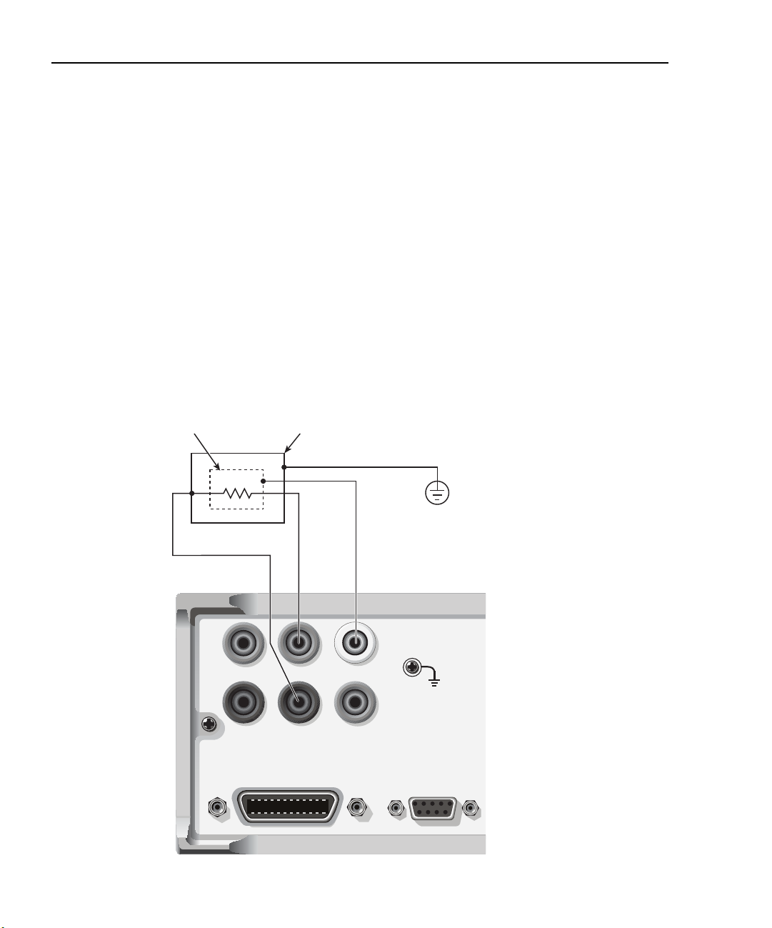
2-8 Connections 2400 Series SourceMeter® User’s Manual
WARNING: NO INTERNAL OPERATOR SERVICA
CAUTION: FOR CONTINUED PROTECTION AGAINST FIR
Guarding methods
Cable guard
Use the high-impedance (cable) guard connection scheme shown in Figure 2-4 for the following source-measure condition:
•Test circuit impedance is >1GΩ.
Note that cable guard must be selected for this connection scheme. See “Guard selection,”
page 2-12, to select cable guard.
A test fixture is typically used when testing high-impedance devices. The test fixture
reduces noise and protects the user from a potentially hazardous voltage on the guard
shield (or plate). See Section 6, “Guard,” for details on using guard.
Note that the test fixture chassis is connected to In/Out LO to reduce noise.
Figure 2-4
High-impedance guarding (cable guard)
Guard Shield Test Fixture
DUT
HI
LO
4-WIRE
SENSE
OUTPUT
IEEE-488
(ENTER IEEE ADDRESS
WITH FRONT PANEL MENU)
INPUT/
Connect to earth safety ground
using #18 AWG wire or larger.
V, Ω
GUARD
GUARD
SENSE
RS232
Page 81

2400 Series SourceMeter® User’s Manual Connections 2-9
Ohms guard
Use the guarded ohms connection schemes shown in Figure 2-5 for the following sourcemeasure operation:
• In-circuit resistance measurements on the DUT where other parasitic leakage
devices are present.
Note that ohms guard must be selected for this connection scheme. Ohms guard is not
available for the 1A range (source or measure). See “Guard selection,” page 2-12, to select
ohms guard and Section 4, “6-wire ohms measurements.”
Figure 2-5 shows how to make connections to measure the resistance of a single resistor
(DUT) in a resistor network. See Section 6, “Guard,” for more information on guarded
ohms measurements.
The basic connection scheme for guarded ohms measurements is shown in Figure 2-5A. If
the guard resistance path (R
enough that the guard voltage at the resistor network is significantly less than the output
voltage at the DUT. This results in leakage current and will corrupt the measurement. To
cancel the effect of IR drop in the GUARD test lead, connect GUARD SENSE to the resistor network as shown in Figure 2-5B. Guard sense ensures that the guard voltage at the
resistor network is the same as the output voltage at the DUT.
<1kΩ, IR drop in the GUARD test lead could be high
G) is
Note that if the DUT is <1kΩ, you should use the 4-wire measurement method (remote
sensing) by connecting SENSE HI and LO to the DUT and enabling remote sense (Figure
2-5C).
NOTE Guard current (IG) must never exceed 50mA. If it does, guard voltage will
become less than the output voltage and corrupt the measurement.
Page 82
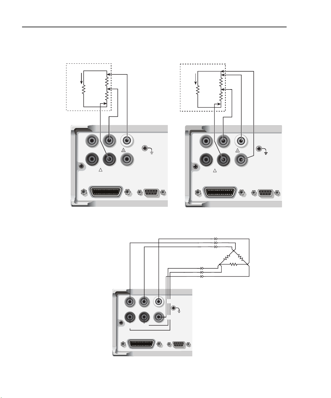
2-10 Connections 2400 Series SourceMeter® User’s Manual
WARNING: NO INTERNAL OPERATOR SERVICA
CAUTION: FOR CONTINUED PROTECTION AGAINST FIR
WARNING: NO INTERNAL OPERATOR SERVICA
CAUTION: FOR CONTINUED PROTECTION AGAINST FI
WARNING: NO INTERNAL OPERATOR SERVICA
CAUTION: FOR CONTINUED PROTECTION AGAINST FI
Figure 2-5
Guarded ohms measurements (ohms guard)
Resistor Network
I
G
R
G
≥1kΩ
HI
LO
INPUT/
4-WIRE
!
OUTPUT
SENSE
IEEE-488
(ENTER IEEE ADDRESS
WITH FRONT PANEL MENU)
Sense Selection: 2-wire (local)
A. Basic connections
V, Ω
GUARD
GUARD
SENSE
RS232
Resistor Network
I
G
R
G
<1kΩ
HI
LO
INPUT/
4-WIRE
!
OUTPUT
SENSE
IEEE-488
(ENTER IEEE ADDRESS
WITH FRONT PANEL MENU)
GUARD
GUARD
SENSE
Sense Selection: 2-wire (local)
B. Connections using guard sense
V, Ω
RS232
4-WIRE
SENSE
(ENTER IEEE ADDRESS
WITH FRONT PANEL
LO
HI
OUTPUT
IEEE-488
INPUT/
V, Ω
GUARD
GUARD
SENSE
RS232
C. 6-wire ohms connections
DUT
Page 83

2400 Series SourceMeter® User’s Manual Connections 2-11
Sense and guard selections
NOTE When sense or guard settings are changed, the OUTPUT will turn OFF.
Sense selection
When using the SENSE HI and LO terminals of the SourceMeter, 4-wire remote sensing
must be selected. When not using these terminals, local sensing must be selected. Sense
selection is explained as follows. See Section 3, “Operation overview,” for details on
sense.
NOTE The SourceMeter defaults to the 2-wire (local) sense mode when the output is
off, regardless of the sense setting. When the output is turned on, the present
sense setting will be in effect.
Front panel sense selection
On power-up, the instrument is automatically set for 2-wire local sense. Perform the following steps to check and/or change the sense selection:
1. Press CONFIG and then the SOURCE V, MEAS V, or Ω key. Changing sense in
one configuration menu changes it in all of the others.
2. For SOURCE V and Ω, use the
item) on SENSE MODE and press ENTER.
and keys to place the cursor (flashing menu
NOTE Cursor position indicates the present sense selection. Two-wire indicates that
local sense is selected, and 4-wire indicates that remote sense is selected. To
retain the present selection, use the EXIT key to back out of the menu structure
and skip the next two steps.
3. To change the sense selection, place the cursor on 4-wire to select remote sense or
on 2-wire to select local sense, and press ENTER.
4. Use the EXIT key to back out of the menu structure.
Remote command sense selection
Use the :SYSTem:RSENse command (Section 18, “SYSTem subsystem”) to choose
between local and remote sensing via remote. For example, send the following command
to enable remote sensing:
:SYST:RSEN ON
Conversely, send this command to disable remote sensing (enable local sensing):
:SYST:RSEN OFF
Page 84

2-12 Connections 2400 Series SourceMeter® User’s Manual
Guard selection
Cable guard is used for high-impedance guarding for cables (i.e., coax and triax) and test
fixtures. Ohms guard provides a high-current guard output, which allows in-circuit
guarded ohms measurements. On power-up, cable guard is selected.
NOTE For 6-wire ohms measurements, use the guard output off mode. See Section 13,
“Front panel output configu ation,” for details on the various output off states
and how to select the guard output off state. See also Section 4, “6-wire ohms
measurements.”
Front panel guard selection
Perform the following steps to check or change the guard selection:
1. Press CONFIG and then SOURCE V, SOURCE I, or Ω. Changing guard in one
configuration menu changes it in all of the others.
2. Using the
press ENTER.
NOTE Cursor position indicates the present guard selection (OHMS or CABLE). To
retain the present selection, use the EXIT key to back out of the menu structure
and skip the next two steps.
and keys, place the cursor (flashing menu item) on GUARD and
3. To change the guard selection, place the cursor on the alternate selection and press
ENTER.
4. Use the EXIT key to back out of the menu structure.
NOTE Do not use ohms guard with coaxial cabling, or oscillations may occur. Ohms
guard cannot be selected on the 1A or higher range (source or measure).
Remote command guard selection
Use the :SYSTem:GUARd command (Section 18, “SYSTem subsystem”) to choose
between cable and ohms guard mode via remote. For example, send the following command to enable ohms guard:
:SYST:GUAR OHMS
Conversely, send this command to enable cable guard:
:SYST:GUAR CABL
Page 85

3
Basic
Source-Measure Operation
• Operation overview — Discusses source-measure capabilities, compliance limit,
and fundamental source-measure configuration.
• Operation considerations — Covers warm-up, auto zero, V-source protection, and
source delay.
• Basic source-measure procedure — Describes the basic procedure for setting up
the SourceMeter for source-measure operations, including selecting the source
function, output values, and compliance limits; choosing measurement range and
function; and turning the output on and off.
• Measure only — Covers how to use the SourceMeter for measurements only.
• Sink operation — Describes sink operation.
Page 86

3-2 Basic Source-Measure Operation 2400 Series SourceMeter® User’s Manual
WARNING - CAUTION
The SourceMeter uses a heat sink to dissipate heat. Also, the Models 2410, 2420, 2430,
and 2440 have a cooling fan. The left side of the case is cut out to expose the black, finned
heat sink. This heat sink gets hot and could be hot enough to cause burns. Even if the
instrument is turned off, you should assume that the heat sink is still hot as it takes considerable time for it to cool off.
WARNING When handling the SourceMeter, NEVER touch the heat sink located
on the left side of the case. This heat sink could be hot enough to cause
burns.
NOTE See Section 1, “Cooling fan,” for operation details on the cooling fan.
Excessive heat could damage the SourceMeter and at the very least, degrade its performance. The SourceMeter must be operated in an environment where the ambient temperature does not exceed 50˚C.
CAUTION To prevent damaging heat build-up, and thus ensure specified perfor-
mance, adhere to the following precautions:
• Keep the heat sink free of dust, dirt, and contaminates, since its
ability to dissipate heat could become impaired.
• Keep the bottom cooling vents from becoming blocked. NEVER
remove the plastic feet and place the SourceMeter directly on a flat
surface. NEVER operate the SourceMeter when it is sitting on a
conformable surface (such as a carpet). This could block the bottom cooling vents.
• Do not position any devices adjacent to the SourceMeter that force
air (heated or unheated) into or onto its surfaces or cooling vents.
This additional airflow could compromise accuracy performance.
• When rack mounting the SourceMeter, make sure there is adequate airflow around the bottom and sides to ensure proper cooling. Adequate airflow enables air temperatures within
approximately one inch of the SourceMeter surfaces to remain
within specified limits under all operating conditions.
• Rack mounting high power dissipation equipment adjacent to the
SourceMeter could cause excessive heating to occur. The specified
ambient temperatures must be maintained around the surfaces of
the SourceMeter to specified accuracies.
• A good measure to ensure proper cooling in rack situations with
convection cooling only is to place the hottest equipment (i.e.,
power supply) at the top of the rack. Precision equipment, such as
the SourceMeter, should be placed as low as possible in the rack
where temperatures are the coolest. Adding spacer panels below
the SourceMeter will help ensure adequate air flow.
Page 87

2400 Series SourceMeter® User’s Manual Basic Source-Measure Operation 3-3
Operation overview
Source-measure capabilities
From the front panel, the SourceMeter can be configured to perform the following
operations:
• Source voltage — Display current and/or voltage measurement
• Source current — Display voltage and/or current measurement
• Measure resistance — Display voltage or current component of measurement
• Measure only (V or I) — Display voltage or current measurement
Voltage and Current — Table 3-1 lists the source and measure limits for the voltage and
current functions. Minimum source-measure levels are listed as follows:
V-Source: ±5µV
V-Measure: ±1µV
I-Source: ±50pA (2400 and 2410)
±500pA (2420, 2425, 2430, and 2440)
I-Measure: ±10pA (2400 and 2410)
±100pA (2420, 2425, 2430, and 2440)
Resistance — The Models 2400 and 2410 can make resistance measurements from
<100Ω to >200MΩ. The Models 2420, 2425, 2430, and 2440 can make resistance
measurements from <2Ω to >20MΩ. For the auto ohms measurement method, the
following ranges are available:
2400 and 2410 — 20Ω, 200Ω, 2kΩ, 20kΩ, 200kΩ, 2MΩ, 20MΩ, and 200MΩ
2420, 2425, 2430, and 2440 — 2Ω, 20Ω, 200Ω, 2kΩ, 20kΩ, 200kΩ, 2MΩ, and 20MΩ
When using the manual ohms measurement method, you cannot select ohms ranges. The
ohms reading is the mathematical result of V/I.
Measure only (V or I) — The SourceMeter can be used exclusively as a voltmeter
(V-Meter) or an ammeter (I-Meter). When used as a V-Meter only, the I-Source is set to
output 0A. When used as an I-meter only, the V-Source is set to output 0V.
Range of operation — The maximum power outputs are summarized as follows:
2400 — 22W (21V at 1.05A or 210V at 105mA)
2410 — 22W (21V at 1.05A or 1100V at 21mA)
2420 — 66W (63V at 1.05A or 21V at 3.15A)
2425 and 2430 — DC Mode: 110W (105V at 1.05A) or 66W (21V at 3.15A)
2430 — Pulse Mode: 1.1kW (105V at 10.5A)
2440 — 66W (42V at 1.05A or 10.5V at 5.25A)
Page 88

3-4 Basic Source-Measure Operation 2400 Series SourceMeter® User’s Manual
The full range of operation is explained in Section 6, “Overheating protection” and “Oper-
ating boundaries.”
NOTE Output transient recovery — The time required for the V-source to recover to its
original value (within 0.1% plus load regulation errors) after a step change in
load current is <250µsec. This does not include the response time of autoranging or the second order effects on loads that are not purely resistive.
Load regulation — The voltage specification for V-source mode load changes is
0.01% +1mV. This means that on the 200mV range, the load current can be
changed from zero to full scale with less than 1.02mV of error. Calculation:
error = (0.01% x 0.2V) + 1mV = 1.02mV
Assuming a 0 to 1A change in current, the output impedance equates to 1.02mΩ
Ω
(1.02mV/1A = 1.02m
). This level can only be achieved using 4-wire remote
sensing.
Table 3-1
Source-measure capabilities
2400 2410
Range Source Measure Range Source Measure
200mV
2V
20V
200V
1µA
10µA
100µA
1mA
10mA
100mA
1A
±210mV
±2.1V
±21V
±210V
±1.05µA
±10.5µA
±105µA
±1.05mA
±10.5mA
±105mA
±1.05A
±211mV
±2.11V
±21.1V
±211V
±1.055µA
±10.55µA
±105.5µA
±1.055mA
±10.55mA
±105.5mA
±1.055A
200mV
2V
20V
1000V
1µA
10µA
100µA
1mA
20mA
100mA
1A
±210mV
±2.1V
±21V
±1.1kV
±1.05µA
±10.5µA
±105µA
±1.05mA
±21mA
±105mA
±1.05A
Max Power = 22W Max Power = 22W
±211mV
±2.11V
±21.1V
±1.1kV
±1.055µA
±10.55µA
±105.5µA
±1.055mA
±21.1mA
±105.5mA
±1.055A
Page 89

2400 Series SourceMeter® User’s Manual Basic Source-Measure Operation 3-5
Table 3-1 (continued)
Source-measure capabilities
2420 2425/2430
Range Source Measure Range Source Measure
200mV
2V
20V
60V
10µA
100µA
1mA
10mA
100mA
1A
3A
±210mV
±2.1V
±21V
±63V
±10.5µA
±105µA
±1.05mA
±10.5mA
±105mA
±1.05A
±3.15A
±211mV
±2.11V
±21.1V
±63.3V
±10.55µA
±105.5µA
±1.055mA
±10.55mA
±105.5mA
±1.055A
±3.165A
200mV
2V
20V
100V
10µA
100µA
1mA
10mA
100mA
1A
3A/10A
±210mV
±2.1V
±21V
±105V
±10.5µA
±105µA
±1.05mA
±10.5mA
±105mA
±1.05A
*
Max Power = 66W 2425 and 2430 Max Power
DC Mode: 110W (105V, 1.05A)
66W (21V, 3.15A)
Pulse Mode: 1.1kW (2430 only)
2440
Range Source Measure
200mV
2V
10V
40V
±210mV
±2.1V
±10.5V
±42V
±211mV
±2.11V
±10.5V
±42V
±211mV
±2.11V
±21.1V
±105.5V
±10.55µA
±105.5µA
±1.055mA
±10.55mA
±105.5mA
±1.055A
**
10µA
100µA
1mA
10mA
100mA
1A
5A
±10.5µA
±105µA
±1.05mA
±10.5mA
±105mA
±1.05A
±5.25A
±10.55µA
±105.5µA
±1.055mA
±10.55mA
±105.5mA
±1.055A
±5.25A
Max Power = 66W
* ±3.15A (DC mode; 2425 and 2430)
±10.5A (Pulse mode; 2430 only)
** ±3.165A (DC mode; 2425 and 2430)
±10.55A (Pulse mode; 2430 only)
Page 90

3-6 Basic Source-Measure Operation 2400 Series SourceMeter® User’s Manual
Compliance limit
When sourcing voltage, the SourceMeter can be set to limit current. Conversely, when
sourcing current, the SourceMeter can be set to limit voltage. The SourceMeter output will
not exceed the compliance limit. Table 3-2 summarizes compliance limits according to
range. See Section 6 for more details on compliance limit.
Table 3-2
Compliance limits
2400 2410 2420
Measure
range
200mV
2V
20V
200V
1µA
10µA
100µA
1mA
10mA
100mA
1A
Measure
range
200mV
2V
20V
100V
Maximum
compliance
value
±210mV
±2.1V
±21V
±210V
±1.05µA
±10.5µA
±105µA
±1.05mA
±10.5mA
±105mA
±1.05A
Measure
range
200mV
2V
20V
1000V
1µA
10µA
100µA
1mA
20mA
100mA
1A
compliance
±210mV
±2.1V
±21V
±1.1kV
±1.05µA
±10.5µA
±105µA
±1.05mA
±21mA
±105mA
±1.05A
2425/2430 2440
Maximum
compliance
value
±210mV
±2.1V
±21V
±105V
Measure
range
200mV
2V
10V
40V
compliance
±210mV
±2.1V
±10.5V
±42V
Maximum
value
Maximum
value
Measure
range
200mV
2V
20V
60V
10µA
100µA
1mA
10mA
100mA
1A
3A
Maximum
compliance
value
±210mV
±2.1V
±21V
±63V
±10.5µA
±105µA
±1.05mA
±10.5mA
±105mA
±1.05A
±3.15A
10µA
100µA
1mA
10mA
100mA
1A
3A/10A
* ±3.15A (2425 and 2430 DC mode)
±10.5A (Pulse mode; 2430 only)
±10.5µA
±105µA
±1.05mA
±10.5mA
±105mA
±1.05A
*
10µA
100µA
1mA
10mA
100mA
1A
5A
±10.5µA
±105µA
±1.05mA
±10.5mA
±105mA
±1.05A
±5.25A
Page 91

2400 Series SourceMeter® User’s Manual Basic Source-Measure Operation 3-7
Setting the compliance limit
Front panel compliance limit
Set the compliance limit from the front panel as follows:
1. Select the desired source and measure functions using the MEAS and SOURCE
keys.
2. Press the EDIT key until the cursor flashes in the compliance (Compl:) display
field.
3. Select the desired compliance range using the RANGE and keys.
4. To increment or decrement the compliance value, use the EDIT and keys to
place the cursor over the digit to be changed, then press the SOURCE or key
to increment or decrement the compliance value.
5. To change the compliance value directly, simply enter the value using the numeric
keys while the cursor is flashing in the compliance display field.
Compliance range synchronization
Enabling this feature will force the measurement range to follow the compliance range setting when autoranging is off. When the compliance value is set, the measurement range
will be on the same range as the compliance setting.
You can enable range synchronization by pressing CONFIG then MEAS V (for voltage) or
MEAS I (for current). Select CMPL-RANGE-SYNC, then ON to enable, or OFF to disable range synchronization.
Remote compliance limit
Table 3-3 summarizes basic commands to program the compliance limit. See Section 18,
“Set compliance parameters,” for more details on these commands. To program the compliance, simply send the command using the desired parameter. For example, the following command sets the current compliance to 50mA:
:SENS:CURR:PROT 50E-3
Similarly, the following command sets the voltage compliance to 4V:
:SENS:VOLT:PROT 4
Table 3-3
Compliance commands
Command Description
:SENSe:CURRent:PROTection <n>
:SENSe:VOLTage:PROTection <n>
Set current compliance (n = compliance).
Set voltage compliance (n = compliance).
Page 92

3-8 Basic Source-Measure Operation 2400 Series SourceMeter® User’s Manual
Basic circuit configurations
The fundamental source-measure configurations for the SourceMeter are shown in Figure
3-1. When sourcing voltage, you can measure current or voltage (configuration A). When
sourcing current, you can measure voltage or current (configuration B).
See Section 6, “Basic circuit configurations,” for more detailed information on these circuit configurations.
Figure 3-1
Fundamental source measure configuration
I-Meter
V-Source
A. Source V
I-Source
B. Source I
V-Meter
I-Meter
V-Meter
Page 93

2400 Series SourceMeter® User’s Manual Basic Source-Measure Operation 3-9
Operation considerations
The following paragraphs discuss warm-up period, auto zero, V-source protection, and
source delay.
Warm-up
The SourceMeter must be turned on and allowed to warm up for at least one hour to
achieve rated accuracies. See Appendix A for specifications.
Auto zero
Every A/D conversion (reading) is calculated from a series of zero, reference, and signal
measurements. With auto zero enabled, all three of these measurements are performed for
each reading to achieve rated accuracy. With auto zero disabled, zero and reference are not
measured. This increases measurement speed, but zero drift will eventually corrupt accuracy. With auto zero disabled, periodically change measurement speed.
Temperature changes across components within the instrument can cause the reference
and zero values for the A/D converter to drift due to thermo-electric effects. Auto zero acts
to negate the effects of drift in order to maintain measurement accuracy over time. Without
auto zero enabled, measurements can drift and become erroneous.
Front panel auto zero
Set the auto zero from the front panel as follows:
1. Press the MENU key.
2. Select A/D CTRL from the main menu, then press ENTER.
3. Select AUTO ZERO, then press ENTER.
4. Select ENABLE or DISABLE as appropriate, then press ENTER.
5. Press EXIT as necessary to return to normal display.
Remote command auto zero
Use the :SYSTem:AZERo command to enable or disable auto zero via remote. See
Section 18, “SYSTem subsystem.” For example, send the following command to disable
auto zero:
:SYST:AZER ON
Conversely, send this command to disable auto-zero:
:SYST:AZER OFF
Page 94

3-10 Basic Source-Measure Operation 2400 Series SourceMeter® User’s Manual
NPLC caching
NPLC caching speeds up source memory sweeps by caching A/D reference and zero values. When NPLC caching is enabled (using the NPLC-CACHE/ENABLE menu selection), the A/D reference and zero values will be saved for up to the 10 most recent voltage,
current, and resistance measurement functions settings. Whenever the integration rate is
changed via the SPEED key, a recalled user setup (using the SAVESETUP/RESTORE
menu selection), or during a source memory recall (either with the SOURCE-MEMORY/
RESTORE menu or during a source memory sweep), NPLC caching will occur. If the
integration rate is already stored in the cache, the stored reference and zero values are
recalled and used. Otherwise, a reference and zero value are acquired and stored in the
cache. If there are already 10 NPLC values stored, the oldest one will be overwritten by
the newest one.
NOTE Auto zero should be disabled for maximum source memory sweep speed; other-
wise the cache is of little use. With auto zero enabled, new A/D reference and
zero values are taken for every reading and saved into the cache, slowing down
sweep operation. However, with auto zero disabled, measurements may drift and
become erroneous. To minimize drift when using NPLC caching with auto zero
disabled, periodically select AUTO-ZERO/ONCE in the A/D-CTRL menu to
force an immediate auto zero update.
NPLC cache setup
Follow the steps below to enable and use NPLC caching with a source memory sweep:
1. Press the MENU key, select A/D-CTRL, then press ENTER.
2. Select AUTO-ZERO, then press ENTER.
3. Choose DISABLE, then press ENTER to disable auto zero.
4. From the A/D CONTROLS menu, select NPLC-CACHE, then press ENTER.
5. Select ENABLE, then press ENTER to enable NPLC caching.
6. Use the EXIT key to back out of the main menu structure.
7. Set up the source memory parameters, and run the source memory sweep. (See
Section 10, “Performing a source memory sweep.”)
Page 95

2400 Series SourceMeter® User’s Manual Basic Source-Measure Operation 3-11
Typical NPLC cache test times
Typically, NPLC caching will decrease source memory sweep times by a factor of three.
The table below shows typical averaged times for a test consisting of 10 sweeps of four
source memory locations with NPLC values for successive memory locations set to 10, 1,
0.1, and 0.01 respectively.
NPLC cache conditions Time
Auto Zero OFF, Caching OFF
Auto Zero ON, Caching OFF
Auto Zero OFF, Caching ON
Auto Zero ON, Caching ON
Auto Zero OFF, Caching ON, Cache empty
V-source protection
Use V-source protection to select the maximum voltage level the SourceMeter can output.
Available settings are listed as follows:
SourceMeter V-Source protection limit settings
2400
2410
2420
2425/2430
2440
These are absolute values with 5% tolerance. The power-on default is NONE.
5.89s
5.89s
2.05s
5.89s
2.5s
20V, 40V, 60V, 80V, 100V, 120V, 160V, NONE (>160V)
20V, 40V, 100V, 200V, 300V, 400V, 500V, NONE (>500V)
6V, 12V, 18V, 24V, 30V, 36V, 48V, NONE (>48V)
10V, 20V, 30V, 40V, 50V, 60V, 80V, NONE (>80V)
4V, 8V, 12V, 16V, 20V, 24V, 32V, NONE (>40V)
Page 96

3-12 Basic Source-Measure Operation 2400 Series SourceMeter® User’s Manual
WARNING Even with the voltage protection limit set to the lowest value, NEVER
touch anything connected to the terminals of the SourceMeter when
the OUTPUT is ON. Always assume that a hazardous voltage (>30V
rms) is present when the OUTPUT is ON.
To prevent damage to DUT (devices under test) or external circuitry,
DO NOT program the V-Source to levels that exceed the voltage protection limit.
Use caution when floating the SourceMeter >30V rms.
Front panel V-source protection
To program V-source protection from the front panel:
1. Press CONFIG then SOURCE V.
2. Select PROTECTION from the displayed choices, then press ENTER.
3. Select the desired protection value, then press ENTER.
4. Press EXIT to return to normal display.
Remote command V-source protection
Use the :SOURce:VOLTage:PROTection command to program the V-source protection
value via remote. See Section 18, “Set voltage limit,” for details. For example, the following command sets the protection value for the Model 2400 or 2410 to 20V:
:SOUR:VOLT:PROT 20
Source delay
NOTE For the Model 2430 Pulse Mode, source delay is not used. The following infor-
The source delay options are used to set the settling time for the source. This source delay
is the delay phase of the Source-Delay-Measure (SDM) cycle. See Section 6. The auto
delay option is used to automatically set the delay. The delay period is range dependent
(Table 3-4).
The delay option is used to manually set the delay from 000.00000 seconds to 9999.99900
seconds. Manually setting the delay disables auto delay.
mation assumes that the Model 2430 is in the DC Mode of operation (“Vpls” or
“Ipls” displayed). To select the DC Mode, press CONFIG and then SOURCE V
or I, select SHAPE from the available menu items, and then select DC.
Page 97

2400 Series SourceMeter® User’s Manual Basic Source-Measure Operation 3-13
Table 3-4
Auto source delay
2400
I-range
1µA
10µA
100µA
1mA
10mA
100mA
1A
*10A range only on Model 2430.
2410
I-range
1µA
10µA
100µA
1mA
20mA
100mA
1A
2420
I-range
10µA
100µA
1mA
10mA
100mA
1A
3A
2425/2430
I-range
10µA
100µA
1mA
10mA
100mA
1A
3A/10A*
2440
I-range
10µA
100µA
1mA
10mA
100mA
1A
5A
Auto delay
(Source V)
3msec
2msec
1msec
1msec
1msec
1msec
1msec
Front panel source delay
To set the manual source delay from the front panel:
1. Press CONFIG then SOURCE V.
2. Select DELAY from the displayed choices, then press ENTER.
3. Enter the desired DELAY value, then press ENTER.
4. Press EXIT to return to normal display.
To set the auto source delay state from the front panel:
1. Press CONFIG then SOURCE V.
2. Select AUTO DELAY from the displayed choices, then press ENTER.
3. Select ENABLE or DISABLE as desired, then press ENTER.
4. Press EXIT to return to normal display.
Auto delay
(Source I)
3msec
1msec
1msec
1msec
1msec
1msec
2msec
Remote command source delay
Use the :SOURce:DELay or :SOURce:DELay:AUTO commands to program the source
delay via remote. (See Section 18, “Set delay,” for details.) For example, the following
command sets the source delay to 500ms:
:SOUR:DEL .5
Similarly, send the following command to enable auto delay:
:SOUR:DEL:AUTO ON
Page 98

3-14 Basic Source-Measure Operation 2400 Series SourceMeter® User’s Manual
Basic source-measure procedure
Output control
Use the ON/OFF OUTPUT key to turn the SourceMeter output on or off for basic sourcemeasure situations. You can also control the output off state (high impedance, normal,
zero, or guard) and program the instrument for auto output off operation. See Section 13
for complete details on these aspects.
WARNING To prevent electric shock, do not make or break connections to the
SourceMeter with the output on. If on, press the ON/OFF OUTPUT
key to turn the output off.
Front panel source-measure procedure
Use the following procedure to perform the basic source-measure operations of the
SourceMeter. See Section 4, “Ohms Measurements,” to measure ohms.
NOTE For the Model 2430, the following procedure pertains to the DC Mode of opera-
tion. Pulse Mode operation is covered in Section 5. If the Model 2430 is in the
Pulse Mode (Vpls or Ipls displayed in the source field), you can select the DC
Mode from the source/pulse configu ation menu. Press CONFIG SOURCE V or
I, select the SHAPE menu item, then select DC. Use the EXIT key to return to the
normal display. In the DC Mode, Vsrc or Isrc is displayed in the source field
The following procedure assumes that the SourceMeter is already connected to
the DUT as explained in Section 2, “Connections.”
Step 1: Select source.
Press SOURCE V to select the V-Source or press SOURCE I to select the I-Source. The
presently programmed source value (V
played. Note that the “OFF” message is displayed to indicate that the source is off
(ON/OFF indicator off).
SRC
or I
) and compliance level (Cmpl) are dis-
SRC
Step 2: Set source level and compliance limit.
The source level is the voltage or current setting of the selected source (V-Source or
I-Source). A compliance limit acts as a power limiter to the DUT and is set to protect the
DUT from damaging currents or voltages. When using the V-Source, a current compliance
is set. When using the I-Source, a voltage compliance is set. Compliance defines the maximum absolute value the SourceMeter can output.
Page 99

2400 Series SourceMeter® User’s Manual Basic Source-Measure Operation 3-15
Note that compliance can also be determined by the measurement range. Depending on
which value is lower, compliance occurs at the programmed value (real compliance) or at
the maximum compliance value for the present fixed measurement range (range compliance). For example, with compliance set to 2V and the 200mV measurement range
selected, compliance will occur at 210mV. On the 20V measurement range, compliance
will occur at 2V. See Section 6, “Compliance limit,” for details on real and range
compliance.
NOTE The SourceMeter must be in the edit mode (EDIT annunciator ON) to set source
and compliance values. The edit mode is selected by pressing the EDIT key.
The flashing digit for the sou ce or compliance reading indicates that the
SourceMeter is in the edit mode. If no editing operation is performed within six
seconds, the edit mode times out and is cancelled. To return to the edit mode,
press EDIT again. While in the edit mode, the EDIT key toggles between the
source value and the compliance value.
The SOURCE
, , , and keys also enable the edit mode. They choose the
last selected field
When editing the source value, the source is updated immediately, allowing you
to adjust the source value while the output is on.
The source value cannot be changed while the SourceMeter is performing a
sweep. This occurs with Output ON and either the SWEEP key is pressed, Offset
Compensation is enabled under Ohms, or OFF-COMP-OHMS, VOLT-COEFF,
or VAR-ALPHA functions are enabled.
When editing the compliance value, compliance is not updated until ENTER is
pressed or the edit mode is allowed to time out.
EDIT always goes to the source field fi st, except while sweeping, in which case
it goes into the compliance field
Source and compliance values cannot be edited in AUTO OHMS mode. MANUAL OHMS allows you to edit source and compliance. See Section 4.
Perform the following steps to edit the source and compliance values:
1. Press EDIT to enter the edit mode. The flashing digit indicates which reading
(source or compliance) is presently selected for editing. If you wish to edit the
other field, press EDIT again.
2. Use the RANGE and keys to select a range that will accommodate the value
you want to set. (See Section 7 for range information.) For best accuracy, use the
lowest possible source range.
3. Enter the desired source or compliance value. There are two methods to edit the
value: value adjust and numeric entry.
Page 100

3-16 Basic Source-Measure Operation 2400 Series SourceMeter® User’s Manual
NOTE To clear the source value to 0V or 0A, press the MENU key while in the edit
source field
•Value adjust — To adjust the value, use the EDIT cursor keys to place the cursor at the appropriate position, and use the SOURCE and keys to increment or decrement the value.
• Numeric entry — When the edit mode is entered, the cursor is located on the
most significant digit of the value. From this position, you can key in the value
using the number keys (0 through 9). After each number is keyed in, the cursor
moves one position to the right. If desired, you can use the EDIT cursor keys
to place the cursor on a digit to be changed, and press the appropriate number
key. The cursor does not have to be on the polarity sign of the value to change
polarity. If the MENU key is pressed, the Source Value will be clear to 0V or
0A.
4. To edit the other field, press EDIT to select it, and repeat steps 1 and 2.
5. When finished editing the source and compliance values, press ENTER or wait six
seconds to exit from the edit mode.
NOTE When a compliance limit value is entered, the SourceMeter automatically goes
to the lowest (most sensitive) compliance range that will accommodate that
value.
For the Models 2400 and 2410, the lowest compliance levels that can be set are
0.00100µA (1nA) and 000.200mV (200µV). For the Models 2420, 2425, 2430,
and 2440, the levels are 00.0100µA (10nA) and 000.200mV (200µV).
Step 3: Select measurement function and range.
Select the desired measurement function by pressing MEAS V (voltage) or MEAS I
(current).
When measuring the source (i.e., Source V Measure V), you cannot select the range using
the measurement RANGE keys. The selected source range determines the measurement
range.
When not measuring the source (i.e., Source V Measure I), measurement range selection
can be done manually or automatically. When using manual ranging, use the lowest possible range for best accuracy. In autorange, the SourceMeter automatically goes to the most
sensitive range to make the measurement.
Measuring voltage — When sourcing current, you can use the RANGE and keys to
manually select the voltage measurement range. You can also press AUTO to select
autoranging. When sourcing voltage, the RANGE keys are inoperative.
Measuring current — When sourcing voltage, you can use the RANGE
manually select the current measurement range. You can also press AUTO to select
autoranging. When sourcing current, the RANGE keys are inoperative.
and keys to
 Loading...