

Page 1
071357601 / October 2018
*P071357601*
1
Part number
Description
Quantity
012178100
Test lead kit
4
CA-180-16A
LAN crossover cable, 16 in.
2
1747107XX
Shielded crossover cable with RJ-45 connector, 5 ft.
1
CO-26
Power line cord
1
CS-568-120A
Green and yellow ground cable, 120 in.
1
0713411XX
Safety precautions
1
4299-13 Rack Mount kit, consisting of:
1
▪ 4076126XX
1U rack rail mount
2
▪ 10-32X3/8PHTRSH
10-32X3/8 Phillips truss head screw
4
▪ 10-32X5/8PHTRSH
10-32X5/8 Phillips truss head screw
8
▪ FA-274
Cage nut
4
Test Equipment Depot - 800.517.8431 - 99 Was
hington Street Melrose, MA 02176 - TestEquipmentDepot.com
Model DMM7512 7½ Digit Sampling Multimeter
Instrument Information
Introduction
This document describes the DMM7512 7½ Digit Multimeter instrument and how it differs from the Model
DMM7510 7½ Digit Multimeter instrument.
The DMM7512 is a no-front-panel version of the DMM7510 that has two DMM modules housed in one
enclosure. Except for the power switch, each module operates independently within the enclosure.
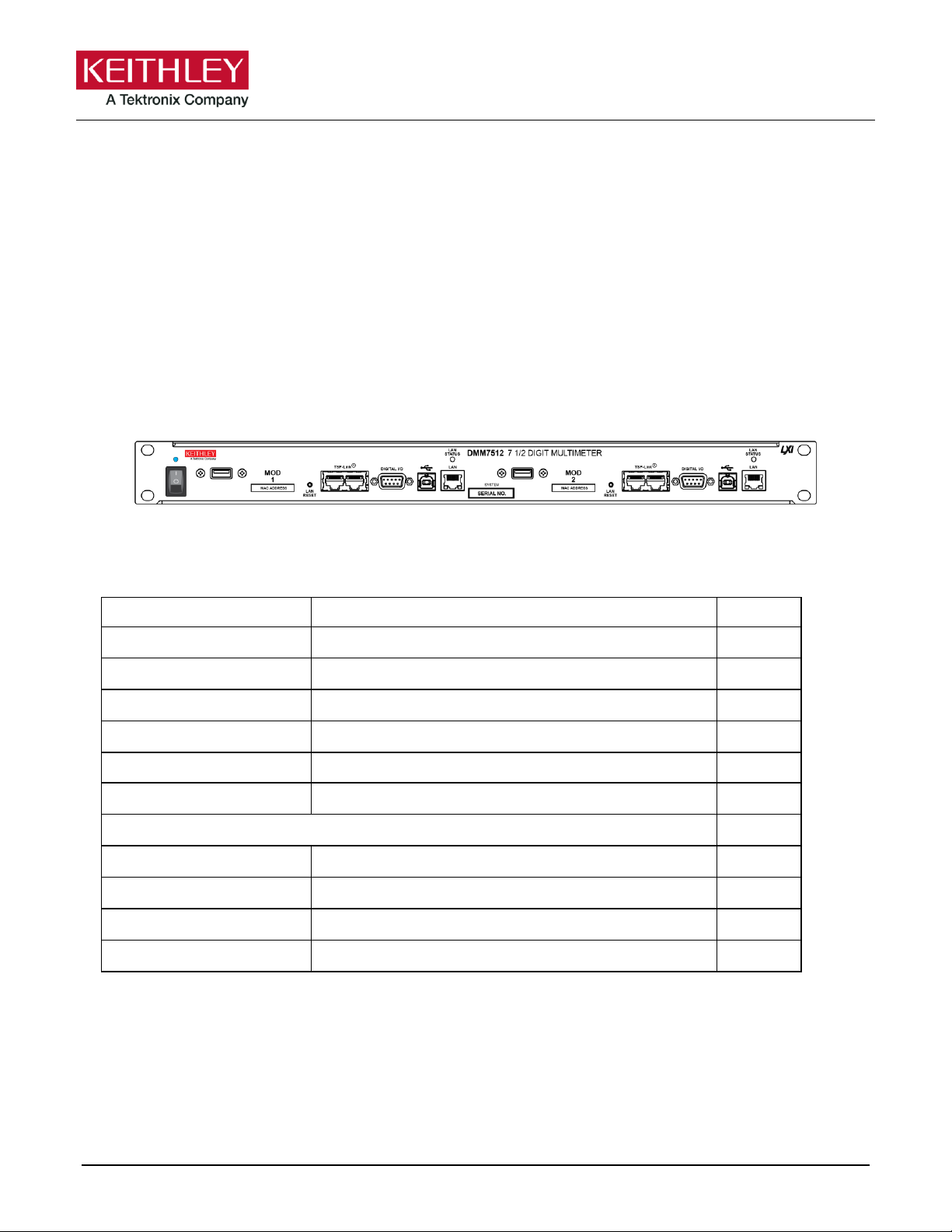
Figure 1: DMM7512 7½ Digit Multimeter
What you should have received
In addition to the DMM7512, you should have received the items in the following table.
Note: XX is the latest revision number.
Page 2

Model DMM7512 7½ Digit Sampling Multimeter Instrument Information
2 071357601 / October 2018
Customer documentation
The DMM7512 is very similar to the DMM7510. This document describes the differences between the
DMM7512 and the DMM7510. Other than the changes described in this document, the products are identical,
so you can use the DMM7510 documents as a resource.
For complete customer documentation, see the Model DMM7510 7½ Digit Multimeter Reference Manual and
other DMM7510 documentation.
To download the DMM7510 documentation:
1. Go to tek.com/product-support.
2. Enter the model number.
If you are using Test Script Builder, use the "Model DMM7510 Command Reference" of the TSB help for
information.
The DMM7510 documentation is available from the tek.com/keithley website in Adobe® Acrobat® PDF format
and includes:
▪ The Model DMM7510 Reference Manual: Includes advanced operation topics and maintenance
information. Programmers looking for a command reference, and users looking for an in-depth description
of the way the instrument works (including troubleshooting and optimization), should refer to the Reference
Manual.
▪ The Model DMM7510 User’s Manual: Provides application examples that you can use as a starting point
to create your own applications.
▪ The Model DMM7510 7½ Digit Graphical Sampling Multimeter Calibration and Adjustment Manual:
Provides calibration and adjustment information. Refer to Verification and adjustment (on page 11) for
detail.
▪ Accessories information: Documentation for accessories.
Capabilities and features
The DMM7512 has the following features:
▪ Ability to perform sensitive measurements on low-level signals
▪ Simplified trigger model with measure configuration lists
▪ USB-A connector for flash-drive support
▪ USB-B connector for communication, control, and data transfer
▪ Limit testing with a built-in comparator for pass/fail testing
▪ Digital I/O for stand-alone binning operations or interface to a component handler
▪ SCPI and Test Script Processor (TSP®) programming languages with remote interface ports (USB and
LAN)
▪ Built-in math expressions and user-defined expressions (using a remote interface)
▪ Filtering to reduce reading noise
▪ A trigger model that supports extensive triggering and synchronization schemes at hardware speeds
▪ LXI® Core Specification 1.4 compliance
▪ TSP-Link® system expansion interface that test system builders can use to connect multiple instruments in
a master and subordinate configuration
▪ Supports USB and ethernet local area network (LAN) connections
Page 3

Model DMM7512 7½ Digit Sampling Multimeter Instrument Information
071357601 / October 2018 3
Differences between the DMM7510 and the DMM7512
The DMM7512 contains two digital multimeters that offer DMM7510 features in a configuration tailored to
rack-mount operation. Most DMM7510 functionality is available, with the following exceptions:
▪ Measure functions for AC voltage, AC current, frequency, period, and capacitance are not available.
▪ The maximum current measurement is 3 A.
▪ There is no front-panel display and there are no keys. You can access a virtual front panel using a remote
LAN interface. Refer to Accessing the virtual front panel (on page 9).
▪ Remote communications setup is different. See Setting up remote communications (on page 7).
▪ Connections for remote communications are on the front panel of the box. See Front-panel overview (on
page 5) for locations.
▪ GPIB functionality is not available.
▪ The Digital I/O connector for each module is oriented so that pin 1 is in the upper right. See Digital I/O port
(on page 6).
▪ The LAN RESET button for each module is on the front panel to the left of the TSP-Link connectors.
▪ Measurement connections are on the rear panel of the instrument only. There is no front terminal or rear
terminal selection. See Rear-panel overview (on page 6) for locations.
▪ The instrument dimensions are different and there are no handles or bumpers. See Dimensions (on
page 4).
▪ The USB VISA resource string for the DMM7512 is USB0::0x05e6::0x7512::[serial
number]::INSTR, where [serial number] is the serial number of the module.
▪ Warmup time for the DMM7512 is four hours.
▪ There is a single power switch and power input for both modules.
▪ Each DMM7512 has three serial numbers, one for the instrument and one for each module. The
instrument serial number is on a label on the front panel. This serial number is not available through a
remote interface. The serial numbers for the modules are on labels on the rear panel. The serial number
for a specific module can be accessed through the virtual front panel or by using the
localnode.serialno command over a remote interface.
▪ The default Command Set for the DMM7512 is TSP instead of SCPI.
Installing the DMM7512
The DMM7512 is intended for mounting in a rack only. For detailed instructions, refer to the documentation for
the Model 4299-13 Rack Mount Kit (part number 0713574XX).
Rack mounting the DMM7512 requires two people. Failure to recognize and observe standard
safety precautions could result in personal injury.
Page 4
Model DMM7512 7½ Digit Sampling Multimeter Instrument Information
4 071357601 / October 2018
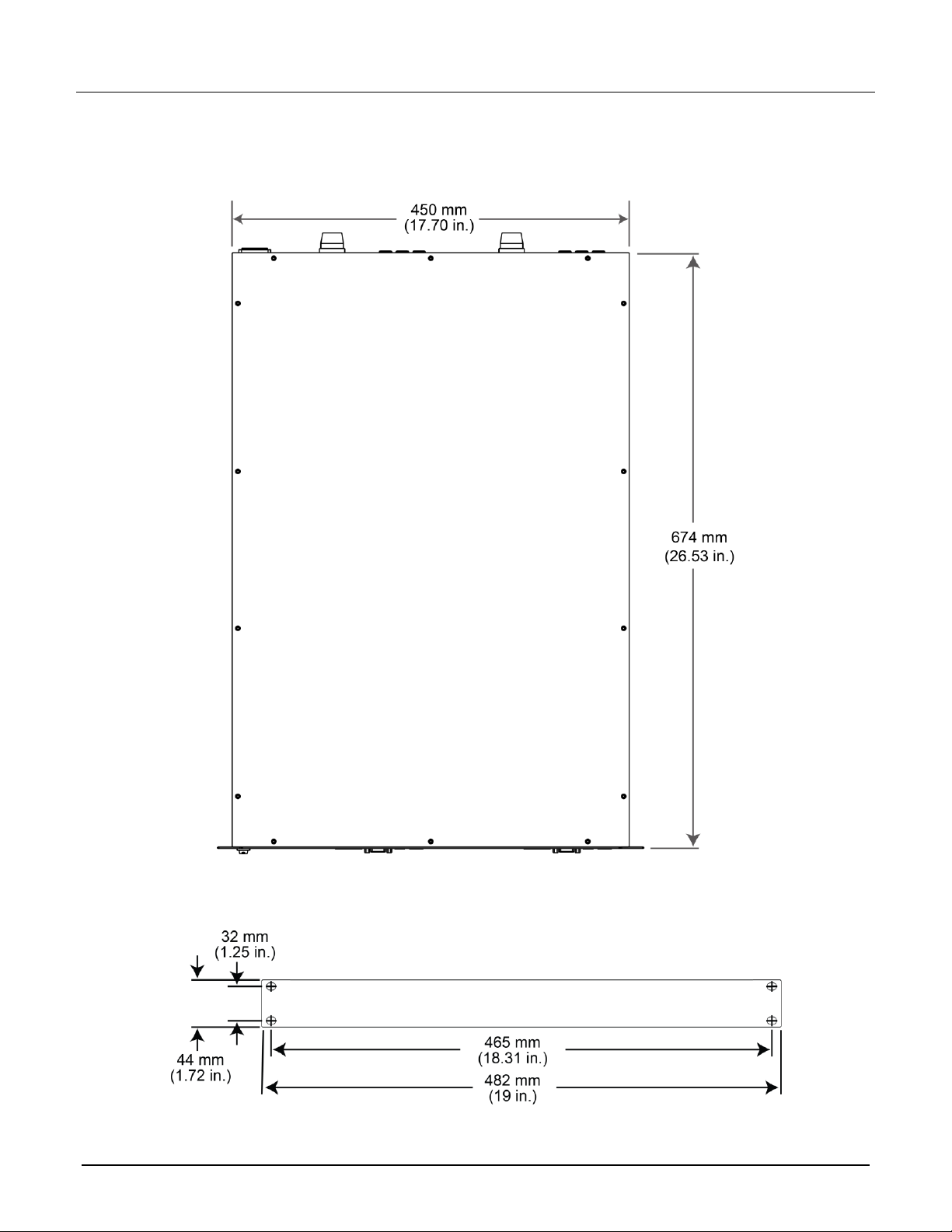
Dimensions
The following figures show the mounting screw locations and other dimensions of the instrument.
Figure 2: DMM7512 top view
Figure 3: Dimensions - front view
Page 5

Model DMM7512 7½ Digit Sampling Multimeter Instrument Information
071357601 / October 2018 5
Power indicator
and switch
The power switch turns the instrument on or off. The indicator is
illuminated when the instrument is on. The power switch powers both
modules.
USB Type A port
USB Type A connection. You can use a USB flash drive to store
reading buffer data, scripts, and user setups. You can also use it to
upgrade the firmware.
LAN RESET
Reverts the LAN settings and the instrument password to default
values. Insert a straightened paper clip into the hole above LAN
RESET to reset the LAN. Refer to Set the IP address to be set
automatically (on page 8) for details on how to use.
TSP-Link ports
Connections for the TSP-Link® system expansion
interface, which builders of test systems can use to
connect multiple instruments in a master and
subordinate configuration. TSP-Link is a high-speed
trigger synchronization and communication bus.
Figure 4: Dimensions - side view
Front-panel overview
The front panel of the DMM7512 is shown below. Descriptions of the controls on the front panel follow the
figure.
Figure 5: DMM7512 front panel
Page 6

Model DMM7512 7½ Digit Sampling Multimeter Instrument Information
6 071357601 / October 2018
Digital I/O port
A digital input/output port that detects and outputs digital signals. The
port provides six digital I/O lines. Each output is set high (+5 V) or low
(0 V) and can read high or low logic levels. Each digital I/O line is an
open-drain signal.
USB Type B port
USB Type B connection for communication, control, and data
transfer.
LAN STATUS
LED indicator
Illuminates when the instrument is connected to a local area network
(LAN).
LAN port
Supports full connectivity on a 10 Mbps or 100 Mbps network. The
DMM7512 is a version 1.5 LXI Device Specification 2016 instrument
that supports TCP/IP and complies with IEEE Std 802.3 (ethernet
LAN). See Setting up remote communications (on page 7).
INPUT and
SENSE terminals
Use the INPUT HI and INPUT LO terminals for all
measurements except current. For current
measurements, use the AMPS connection with the
INPUT LO terminal.
Use the SENSE HI and SENSE LO terminals and the
INPUT terminals with the 4-wire resistance, 3-wire
and 4-wire RTD temperature, and DC voltage ratio
functions.
AMPS connection
3 A, 250 V current connector for DC current and digitize DC current
10 µA to 3 A ranges.
Rear-panel overview
The rear panel of the DMM7512 is shown below. The descriptions of the rear-panel components follow the
figure.
Figure 6: 7512 rear panel
Page 7

Model DMM7512 7½ Digit Sampling Multimeter Instrument Information
071357601 / October 2018 7
Measurement
input fuse
Fast-acting current-input fuse.
For continued protection against fire hazard, replace this fuse with a
fuse of the same type and rating (Keithley part number
DMM7510-FUSE-3A).
EXT TRIG
IN/OUT terminal
This terminal is a TTL-compatible input/output line with a 0 to 5 V
logic signal. You can use this line for triggering by using the transition
of the line state to initiate an action. The instrument can generate
output trigger pulses and detect input trigger pulses on this line.
Chassis ground
Ground screw for connections to chassis ground. This provides
a connection terminal to the equipment frame.
Line fuse and
power receptacle
Connect the line cord to the power receptacle and a grounded AC
power outlet. The line fuse, located just above the power receptacle,
protects the power line input of the instrument.
Setting up remote communications
Each device on a LAN (corporate or private) requires a unique IP address. Contact your corporate information
technology (IT) department for details about obtaining an IP address before you connect the DMM7512 to a
corporate or private network.
Contact your corporate IT department for permission before you connect the DMM7512 to a
corporate network.
Each module in the instrument has a separate IP configuration. The IP configuration persists through a power
cycle.
When the DMM7512 is shipped, the IP configurations for each module are set to Manual and are set to the
following values:
▪ IP address, module 1: 192.168.0.3
▪ IP address, module 2: 192.168.0.4
▪ Gateway: 192.168.0.1
▪ Subnet mask: 255.255.255.0
These values persist through a power cycle unless they are changed or the LAN RESET button is selected. If
the LAN RESET button is selected, the TCP/IP mode is set to automatic.
Page 8

Model DMM7512 7½ Digit Sampling Multimeter Instrument Information
8 071357601 / October 2018
Set the IP address to be set automatically
When the TCP/IP configuration mode is set to Automatic, a DHCP server automatically sets the IP address,
subnet mask, and the default gateway. To use this option, a DHCP server must be available on the network.
The following steps reset the TCP/IP configuration, which also resets the instrument password. This
allows remote access to LXI web page controls that may have been password-protected before the
reset.
To use the LAN RESET switch to select Automatic configuration:
1. Turn on instrument power.
2. Wait for the instrument to complete power up.
3. Insert a straightened paper clip into the recessed LAN RESET switch on the DMM7512 front panel,
pressing the switch briefly. The LAN status indicator illuminates when the connection is established.
4. To find the IP address that was automatically applied, use the LXI Discovery Tool, a utility that is available
from the Resources tab of the LXI Consortium website (http://www.lxistandard.org/).
Page 9

Model DMM7512 7½ Digit Sampling Multimeter Instrument Information
071357601 / October 2018 9
Accessing the virtual front panel
If you have a LAN connection, you can access the web interface of each module in the instrument. Each
module has its own IP address and is controlled separately. The web interface for each module includes a
virtual front panel, which you can use to control the module. You can access the web interface for both modules
at the same time.
To access the web interface and virtual front panel:
1. Open a web browser on the host computer.
2. Enter the IP address of the module in the address box of the web browser. For example, the default
address for module 1 is 192.168.0.3, so you enter 192.168.0.3 in the browser address box to access
module 1.
The default IP address for module 2 is 192.168.0.4, so to access module 2, enter 192.168.0.4.
3. Press Enter on the computer keyboard to open the web page for the module.
4. If prompted, enter a user name and password. The default is admin for both.
5. Select Virtual Front Panel from the left pane.
An example of the virtual front panel is shown below.
Figure 7: DMM7512 virtual front panel
Page 10

Model DMM7512 7½ Digit Sampling Multimeter Instrument Information
10 071357601 / October 2018
Line fuse
Line voltage
Rating
Keithley part number
100 V to 240 V
250 V, 3.15 A, Slow Blow 5 x 20 mm
FU-106-3.15
Line fuse replacement
A fuse on the DMM7512 rear panel protects the power line input of the instrument.
Disconnect the line cord at the rear panel and remove all test leads connected to the
instrument before replacing a line fuse. Failure to do so could expose the operator to
hazardous voltages that could result in personal injury or death.
The fuse drawer is above the AC receptacle on the rear panel of the DMM7512, as shown in the following
figure.
Figure 8: Fuse replacement
To prevent injury, death, or instrument damage, use only the correct fuse type (see table).
To replace the line fuse:
1. Power off the instrument and remove the line cord.
2. There is a small tab at the bottom of the fuse drawer. Using a small screwdriver, pry this tab from the AC
receptacle.
3. Slide the fuse drawer out to access to the fuse.
4. Snap the fuse out of the drawer and replace it with the same type, as specified in the table below.
5. Push the fuse drawer back into the module.
If a fuse continues to become damaged, a circuit malfunction exists and must be corrected. Return the
instrument to Keithley Instruments for repair.
Page 11

Model DMM7512 7½ Digit Sampling Multimeter Instrument Information
071357601 / October 2018 11
Verification and adjustment
The DMM7512 contains two independent DMM modules that each support a sub-set of DMM7510 functions
and specifications. For supported functions, the commands are identical to DMM7510.
To verify and adjust the DMM7512, use the procedures in the Model DMM7510 7½ Digit Graphical Sampling
Multimeter Calibration and Adjustment Manual (Keithley document number DMM7510-905-01), with the
following exceptions:
▪ The DMM7512 contains two independent DMM modules. Each module requires separate calibration and
adjustment.
▪ The DMM7512 does not support AC voltage or AC current functions, and it does not support the 10 A
current range. Therefore, only DC verification and adjustment steps are required.
▪ Each DMM7512 module has only one block of inputs, which is on the rear panel. The DMM7512 inputs are
equivalent to the front-panel inputs of the DMM7510. Therefore, only use cal.adjust.dc() commands
when making calibration adjustments. The cal.adjust.rear.dc() commands are not used for the
DMM7512.
▪ The DMM7512 does not include a GPIB interface or front-panel display. You must perform calibration and
adjustment using USB or LAN connection methods. You can use the methods described in "Adjustment
command timing and error checking" in the Calibration and Adjustment Manual.
▪ Due to the heavier metal chassis thermal mass, the DMM7512 requires more warm-up time than the
DMM7510. Allow 4 hours warm up before performance verification or calibration adjustment.
▪ Refer to the DMM7512 specifications (document number SPEC-DMM7512) when calculating performance
verification limits as described in "Calibration Verification Limits" in the Calibration and Adjustment Manual
▪ Where front panel procedures (such as autocalibration) are referred to, you can use the virtual front panel
if you have a LAN connection. Refer to Accessing the virtual front panel (on page 9).
Other differences between the DMM7510 and DMM7512 procedures:
▪ In the "Recommended test equipment" list in the Calibration and Adjustment Manual, the Keithley
Instruments 3390 and IET Labs, Inc., 1423-A and HACS-Z-A-2E 1uF instruments are not required.
▪ In the "Test Summary" list, omit the following verification procedures:
▪ AC voltage verification
▪ Frequency verification
▪ AC current verification
▪ Capacitance verification
▪ All rear-panel (10 A) tests
▪ In the "Adjustment" section, perform only calibration steps DC step 0 through DC step 5 as described in
"Front-terminal adjustment steps." Omit all other adjustment steps.
Software and drivers
Page 12

12 071357601 / October 2018
Safety precautions
The following safety precautions should be observed before using this product and any associated instrumentation. Although
some instruments and accessories would normally be used with nonhazardous voltages, there are situations where hazardous
conditions may be present.
This product is intended for use by personnel who recognize shock hazards and are familiar with the safety precautions required
to avoid possible injury. Read and follow all installation, operation, and maintenance information carefully before using the
product. Refer to the user documentation for complete product specifications.
If the product is used in a manner not specified, the protection provided by the product warranty may be impaired.
The types of product users are:
Responsible body is the individual or group responsible for the use and maintenance of equipment, for ensuring that the
equipment is operated within its specifications and operating limits, and for ensuring that operators are adequately trained.
Operators use the product for its intended function. They must be trained in electrical safety procedures and proper use of the
instrument. They must be protected from electric shock and contact with hazardous live circuits.
Maintenance personnel perform routine procedures on the product to keep it operating properly, for example, setting the line
voltage or replacing consumable materials. Maintenance procedures are described in the user documentation. The procedures
explicitly state if the operator may perform them. Otherwise, they should be performed only by service personnel.
Service personnel are trained to work on live circuits, perform safe installations, and repair products. Only properly trained
service personnel may perform installation and service procedures.
Keithley products are designed for use with electrical signals that are measurement, control, and data I/O connections, with low
transient overvoltages, and must not be directly connected to mains voltage or to voltage sources with high transient
overvoltages. Measurement Category II (as referenced in IEC 60664) connections require protection for high transient
overvoltages often associated with local AC mains connections. Certain Keithley measuring instruments may be connected to
mains. These instruments will be marked as category II or higher.
Unless explicitly allowed in the specifications, operating manual, and instrument labels, do not connect any instrument to mains.
Exercise extreme caution when a shock hazard is present. Lethal voltage may be present on cable connector jacks or test
fixtures. The American National Standards Institute (ANSI) states that a shock hazard exists when voltage levels greater than
30 V RMS, 42.4 V peak, or 60 VDC are present. A good safety practice is to expect that hazardous voltage is present in any
unknown circuit before measuring.
Operators of this product must be protected from electric shock at all times. The responsible body must ensure that operators
are prevented access and/or insulated from every connection point. In some cases, connections must be exposed to potential
human contact. Product operators in these circumstances must be trained to protect themselves from the risk of electric shock. If
the circuit is capable of operating at or above 1000 V, no conductive part of the circuit may be exposed.
Do not connect switching cards directly to unlimited power circuits. They are intended to be used with impedance-limited
sources. NEVER connect switching cards directly to AC mains. When connecting sources to switching cards, install protective
devices to limit fault current and voltage to the card.
Before operating an instrument, ensure that the line cord is connected to a properly-grounded power receptacle. Inspect the
connecting cables, test leads, and jumpers for possible wear, cracks, or breaks before each use.
When installing equipment where access to the main power cord is restricted, such as rack mounting, a separate main input
power disconnect device must be provided in close proximity to the equipment and within easy reach of the operator.
For maximum safety, do not touch the product, test cables, or any other instruments while power is applied to the circuit under
test. ALWAYS remove power from the entire test system and discharge any capacitors before: connecting or disconnecting
cables or jumpers, installing or removing switching cards, or making internal changes, such as installing or removing jumpers.
Do not touch any object that could provide a current path to the common side of the circuit under test or power line (earth)
ground. Always make measurements with dry hands while standing on a dry, insulated surface capable of withstanding the
voltage being measured.
Page 13

071357601 / October 2018 13
For safety, instruments and accessories must be used in accordance with the operating instructions. If the instruments or
accessories are used in a manner not specified in the operating instructions, the protection provided by the equipment may be
impaired.
Do not exceed the maximum signal levels of the instruments and accessories. Maximum signal levels are defined in the
specifications and operating information and shown on the instrument panels, test fixture panels, and switching cards.
When fuses are used in a product, replace with the same type and rating for continued protection against fire hazard.
Chassis connections must only be used as shield connections for measuring circuits, NOT as protective earth (safety ground)
connections.
If you are using a test fixture, keep the lid closed while power is applied to the device under test. Safe operation requires the use
of a lid interlock.
If a screw is present, connect it to protective earth (safety ground) using the wire recommended in the user documentation.
The symbol on an instrument means caution, risk of hazard. The user must refer to the operating instructions located in the
user documentation in all cases where the symbol is marked on the instrument.
The symbol on an instrument means warning, risk of electric shock. Use standard safety precautions to avoid personal
contact with these voltages.
The symbol on an instrument shows that the surface may be hot. Avoid personal contact to prevent burns.
The symbol indicates a connection terminal to the equipment frame.
If this symbol is on a product, it indicates that mercury is present in the display lamp. Please note that the lamp must be
properly disposed of according to federal, state, and local laws.
The WARNING heading in the user documentation explains hazards that might result in personal injury or death. Always read
the associated information very carefully before performing the indicated procedure.
The CAUTION heading in the user documentation explains hazards that could damage the instrument. Such damage may
invalidate the warranty.
The CAUTION heading with the symbol in the user documentation explains hazards that could result in moderate or minor
injury or damage the instrument. Always read the associated information very carefully before performing the indicated
procedure. Damage to the instrument may invalidate the warranty.
Instrumentation and accessories shall not be connected to humans.
Before performing any maintenance, disconnect the line cord and all test cables.
To maintain protection from electric shock and fire, replacement components in mains circuits — including the power
transformer, test leads, and input jacks — must be purchased from Keithley. Standard fuses with applicable national safety
approvals may be used if the rating and type are the same. The detachable mains power cord provided with the instrument may
only be replaced with a similarly rated power cord. Other components that are not safety-related may be purchased from other
suppliers as long as they are equivalent to the original component (note that selected parts should be purchased only through
Keithley to maintain accuracy and functionality of the product). If you are unsure about the applicability of a replacement
component, call a Keithley office for information.
Unless otherwise noted in product-specific literature, Keithley instruments are designed to operate indoors only, in the following
environment: Altitude at or below 2,000 m (6,562 ft); temperature 0 °C to 50 °C (32 °F to 122 °F); and pollution degree 1 or 2.
To clean an instrument, use a cloth dampened with deionized water or mild, water-based cleaner. Clean the exterior of the
instrument only. Do not apply cleaner directly to the instrument or allow liquids to enter or spill on the instrument. Products that
consist of a circuit board with no case or chassis (e.g., a data acquisition board for installation into a computer) should never
require cleaning if handled according to instructions. If the board becomes contaminated and operation is affected, the board
should be returned to the factory for proper cleaning/servicing.
Safety precaution revision as of June 2017.
 Loading...