

Page 1

www.keithley.com
Model DMM7510
7½ Digit Graphical Sampling Multimeter
User’s Manual
DMM7510-900-01 Rev. B / May 2015
*PDMM751090001B*
DMM7510-900-01B
A Greater Measure of Confidence
Page 2

Model DMM7510
7½ Digit Multimeter
User's Manual
© 2015, Keithley Instruments
Cleveland, Ohio, U.S.A.
All rights reserved.
Any unauthorized reproduction, photocopy, or use of the information herein, in whole or in part,
without the prior written approval of Keithley Instruments is strictly prohibited.
®
, TSP-Link®, and TSP-Net® are trademarks of Keithley Instruments. All Keithley Instruments
TSP
product names are trademarks or registered trademarks of Keithley Instruments, Inc. Other brand
names are trademarks or registered trademarks of their respective holders.
The Lua 5.0 software and associated documentation files are copyright © 1994 - 2013, Tecgraf,
PUC-Rio. Terms of license for the Lua software and associated documentation can be accessed at
the Lua licensing site (http://www.lua.org/license.html).
Document number: DMM7510-900-01 Rev. B / May 2015
Page 3

Page 4

Safety precaut ions
The following safety precautions should be observed before using this product and any associated instrumentation. Although
some instruments and accessories would normally be used with nonhazardous voltages, there are situations where hazardous
conditions may be present.
This product is intended for use by qualified personnel who recognize shock hazards and are familiar with the safety precautions
required to avoid possible injury. Read and follow all installation, operation, and maintenance information carefully before using
the product. Refer to the user documentation for complete product specifications.
If the product is used in a manner not specified, the protection provided by the product warranty may be impaired.
The types of product users are:
Responsible body is the individual or group responsible for the use and maintenance of equipment, for ensuring that the
equipment is operated within its specifications and operating limits, and for ensuring that operators are adequately trained.
Operators use the product for its intended function. They must be trained in electrical safety procedures and proper use of the
instrument. They must be protected from electric shock and contact with hazardous live circuits.
Maintenance personnel perform routine procedures on the product to keep it operating properly, for example, setting the line
voltage or replacing consumable materials. Maintenance procedures are described in the user documentation. The procedures
explicitly state if the operator may perform them. Otherwise, they should be performed only by service personnel.
Service personnel are trained to work on live circuits, perform safe installations, and repair products. Only properly trained
service personnel may perform installation and service procedures.
Keithley Instruments products are designed for use with electrical signals that are measurement, control, and data I/O
connections, with low transient overvoltages, and must not be directly connected to mains voltage or to voltage sources with high
transient overvoltages. Measurement Category II (as referenced in IEC 60664) connections require protection for high transient
overvoltages often associated with local AC mains connections. Certain Keithley measuring instruments may be connected to
mains. These instruments will be marked as category II or higher.
Unless explicitly allowed in the specifications, operating manual, and instrument labels, do not connect any instrument to mains.
Exercise extreme caution when a shock hazard is present. Lethal voltage may be present on cable connector jacks or test
fixtures. The American National Standards Institute (ANSI) states that a shock hazard exists when voltage levels greater than
30 V RMS, 42.4 V peak, or 60 VDC are present. A good safety practice is to expect that hazardous voltage is present in any
unknown circuit before measuring.
Operators of this product must be protected from electric shock at all times. The responsible body must ensure that operators
are prevented access and/or insulated from every connection point. In some cases, connections must be exposed to potential
human contact. Product operators in these circumstances must be trained to protect themselves from the risk of electric shock. If
the circuit is capable of operating at or above 1000 V, no conductive part of the circuit may be exposed.
Do not connect switching cards directly to unlimited power circuits. They are intended to be used with impedance-limited
sources. NEVER connect switching cards directly to AC mains. When connecting sources to switching cards, install protective
devices to limit fault current and voltage to the card.
Before operating an instrument, ensure that the line cord is connected to a properly-grounded power receptacle. Inspect the
connecting cables, test leads, and jumpers for possible wear, cracks, or breaks before each use.
When installing equipment where access to the main power cord is restricted, such as rack mounting, a separate main input
power disconnect device must be provided in close proximity to the equipment and within easy reach of the operator.
For maximum safety, do not touch the product, test cables, or any other instruments while power is applied to the circuit under
test. ALWAYS remove power from the entire test system and discharge any capacitors before: connecting or disconnecting
cables or jumpers, installing or removing switching cards, or making internal changes, such as installing or removing jumpers.
Do not touch any object that could provide a current path to the common side of the circuit under test or power line (earth)
ground. Always make measurements with dry hands while standing on a dry, insulated surface capable of withstanding the
voltage being measured.
For safety, instruments and accessories must be used in accordance with the operating instructions. If the instruments or
Page 5

accessories are used in a manner not specified in the operating instructions, the protection prov ided by the equi pm ent ma y be
impaired.
Do not exceed the maximum signal levels of the instruments and accessories, as defined in the specifications and operating
information, and as shown on the instrument or test fixture panels, or switching card.
When fuses are used in a product, replace with the same type and rating for continued protection against fire hazard.
Chassis connections must only be used as shield connections for measuring circuits, NOT as protective earth (safety ground)
connections.
If you are using a test fixture, keep the lid closed while power is applied to the device under test. Safe operation requires the use
of a lid interlock.
screw is present, connect it to protective earth (safety ground) using the wire recommended in the u ser doc ume nt at io n.
If a
The symbol on an instrument means caution, risk of danger. The user must refer to the operating instructions located in the
user documentation in all cases where the symbol is mark ed on the instru ment .
The
contact with these voltages.
The
The
If this symbol is on a product, it indicates that mercury is present in the display lamp. Please note that the lamp must be
properly disposed of according to federal, state, and local laws.
The WARNING heading in the user documentation explains dangers that might result in personal injury or death. Always read
the associated information very carefully before performing the indicated procedure.
The CAUTION heading in the user documentation explains h az ards that coul d dama ge the instr ume nt. Such dam age may
invalidate the warranty.
Instrumentation and accessories shall not be connected to humans.
Before performing any maintenance, disconnect the line cord and all test cables.
To maintain protection from electric shock and f ire, r epl ace m ent comp one nts in mai ns cir cuit s — inc lud ing the power
transformer, test leads, and input jacks — must be purchased from Keithley Instruments. Standard fuses with applicable national
safety approvals may be used if the rating and type are the same. Other components that are not safety-related may be
purchased from other suppliers as long as they are equivalent to the original component (note that selected parts should be
purchased only through Keithley Instruments to maintain accuracy and functionality of the product). If you are unsure about the
applicability of a replacement component, call a Keithley Instruments office for information.
To clean an instrument, use a damp cloth or mild, water-based cleaner. Clean the exterior of the instrument only. Do not apply
cleaner directly to the instrument or allow liquids to enter or spill on the instrument. Products that consist of a circuit board with
no case or chassis (e.g., a data acquisition board for installation into a computer) should never require cleaning if handled
according to instructions. If the board becomes contaminated and operation is affected, the board should be returned to the
factory for proper cleaning/servicing.
symbol on an instrument means caution, risk of electric shock. Use standard safety precautions to avoid personal
symbol on an instrument shows that the surface may be hot. Avoid personal contact to prevent burns.
symbol indicates a connection terminal to the equipment frame.
Safety precaution revision as of January 2013.
Page 6

Table of Contents
Introduction ............................................................................................................... 1-1
Welcome .............................................................................................................................. 1-1
Introduction to this manual ................................................................................................... 1-1
Extended warranty ............................................................................................................... 1-2
Contact information .............................................................................................................. 1-2
CD-ROM contents ................................................................................................................ 1-2
Organization of manual sections .......................................................................................... 1-2
Application examples ........................................................................................................... 1-3
Using the front-panel interface ................................................................................ 2-1
Front-panel overview ............................................................................................................ 2-1
Instrument power ................................................................................................................. 2-4
Connect the power cord ............................................................................................................ 2-4
Turn the Model DMM7510 on or off .......................................................................................... 2-4
Touchscreen display ............................................................................................................ 2-5
Select items on the touchscreen ............................................................................................... 2-5
Scroll bars ................................................................................................................................. 2-5
Enter information ....................................................................................................................... 2-6
Adjust the backlight brightness and dimmer .............................................................................. 2-7
Review event messages ........................................................................................................... 2-7
Interactive swipe screens ..................................................................................................... 2-7
Swipe screen heading bar ......................................................................................................... 2-8
FUNCTIONS swipe screen ....................................................................................................... 2-9
SETTINGS swipe screen .......................................................................................................... 2-9
STATISTICS swipe screen...................................................................................................... 2-10
SECONDARY swipe screen.................................................................................................... 2-11
USER swipe screen ................................................................................................................ 2-12
GRAPH swipe screen ............................................................................................................. 2-12
Menu overview ................................................................................................................... 2-13
Measure menu ........................................................................................................................ 2-13
Views menu............................................................................................................................. 2-14
Trigger menu ........................................................................................................................... 2-14
Scripts menu ........................................................................................................................... 2-15
System menu .......................................................................................................................... 2-15
Using a remote interface .......................................................................................... 3-1
Remote communications interfaces ..................................................................................... 3-1
Supported remote interfaces ................................................................................................ 3-2
GPIB communications .......................................................................................................... 3-2
Install the GPIB driver software ................................................................................................. 3-3
Install the GPIB cards in your computer .................................................................................... 3-3
Connect GPIB cables to your instrument .................................................................................. 3-3
Set the GPIB address ............................................................................................................... 3-4
LAN communications ........................................................................................................... 3-5
Page 7

Table of Contents
User's Manual
Model DMM7510 7½ Digit Multimeter
Set up LAN communications on the instrument ........................................................................ 3-5
Set up LAN communications on the computer .......................................................................... 3-6
USB communications ........................................................................................................... 3-7
Connect a computer to the Model DMM7510 using USB .......................................................... 3-8
Communicate with the instrument ............................................................................................. 3-8
Using the web interface...................................................................................................... 3-11
Connect to the instrument web interface ................................................................................. 3-12
LAN troubleshooting suggestions ............................................................................................ 3-12
Identify the instrument ............................................................................................................. 3-14
Review events in the event log ................................................................................................ 3-14
Determining the command s et you will use ....................................................................... 3-14
Making basic front-panel measurements ................................................................ 4-1
Introduction .......................................................................................................................... 4-1
Equipment required for this example ................................................................................... 4-1
Device connections .............................................................................................................. 4-2
Basic front-panel measurements ......................................................................................... 4-3
Measuring DC voltage with high accuracy.............................................................. 5-1
Introduction .......................................................................................................................... 5-1
Equipment required .............................................................................................................. 5-1
Device connections .............................................................................................................. 5-1
High-accurac y DC voltage measurements .......................................................................... 5-3
Using the front panel ................................................................................................................. 5-3
Using SCPI commands ............................................................................................................. 5-4
Using TSP commands .............................................................................................................. 5-5
Test results................................................................................................................................ 5-6
Measuring 4-wire resistance with offset compensation ......................................... 6-1
Introduction .......................................................................................................................... 6-1
Equipment required .............................................................................................................. 6-1
Device connections .............................................................................................................. 6-2
4-wire resistance measurements with offset compensation ................................................ 6-3
Using the front panel ................................................................................................................. 6-4
Using SCPI commands ............................................................................................................. 6-4
Using TSP commands .............................................................................................................. 6-5
Test results................................................................................................................................ 6-5
Sampling temperature at a set time interval ........................................................... 7-1
Introduction .......................................................................................................................... 7-1
Equipment required .............................................................................................................. 7-1
Device connections .............................................................................................................. 7-2
Sample temperatures at a specific time interval .................................................................. 7-3
Using SCPI commands ............................................................................................................. 7-4
Page 8

Model DMM7510
of Contents
7½ Digit Multimeter User's Manual Table
Using TSP ................................................................................................................................. 7-5
Test results................................................................................................................................ 7-6
Grading and binning resistors ................................................................................. 8-1
Introduction .......................................................................................................................... 8-1
Instrument connections ........................................................................................................ 8-2
Resistor grading and binning test ........................................................................................ 8-2
Trigger model template: GradeBinning ..................................................................................... 8-3
Overview of the application ....................................................................................................... 8-4
Using SCPI commands ............................................................................................................. 8-5
Using TSP commands .............................................................................................................. 8-6
Integrating with a Model 3706A-S using TSP-Link ................................................. 9-1
Introduction .......................................................................................................................... 9-1
Equipment required .............................................................................................................. 9-1
Device connections .............................................................................................................. 9-2
Integrating with a Model 3706A-S test ................................................................................. 9-4
Set up TSP nodes on the Model DMM7510 and Model 3706A-S ............................................. 9-4
Using SCPI................................................................................................................................ 9-5
Using TSP ................................................................................................................................. 9-5
Capturing and analyzing waveforms ..................................................................... 10-1
Introduction ........................................................................................................................ 10-1
Equipment required ............................................................................................................ 10-1
Device connections ............................................................................................................ 10-2
Testing a buck converter .................................................................................................... 10-3
Ripple noise on the output voltage .......................................................................................... 10-4
Duty cycle from switch node voltage ....................................................................................... 10-7
Inductor current linearity with varying load ............................................................................ 10-11
Power-up behavior ................................................................................................................ 10-15
Troubleshooting FAQs ........................................................................................... 11-1
About this section ............................................................................................................... 11-1
Where can I find updated drivers? ..................................................................................... 11-1
Is there any software to help me get started? .................................................................... 11-2
How do I upgrade the firmware? ........................................................................................ 11-2
Why can't the Model DMM7510 read my USB flash drive? ............................................... 11-2
How do I change the command set? ................................................................................. 11-3
How do I save the present state of the instrument? .......................................................... 11-4
Why did my settings change? ............................................................................................ 11-4
What are the Quick Setup options? ................................................................................... 11-5
Page 9

Table of Contents
User's Manual
Model DMM7510 7½ Digit Multimeter
Next steps ............................................................................................................... 12-1
Additional Model DMM7510 information ............................................................................ 12-1
Index ........................................................................................................................... I-1
Page 10

Application examples ............................................................... 1-3
Welcome
Thank you for choosing a Keithley Instruments product. The Model DMM7510 is a 7½ digit graphical
sampling multimeter that expands standard DMM functions with high-speed digiti zing and large
graphical color touchscreen display. This DMM offers a broad range of measurement capabilities,
including 17 measurement functions. In addition to industry-leading DC accuracies, functions such as
capacitance, 10 amp current, and 18-bit current and voltage digitizing are included. Tying all these
features together is a large 5-inch color touchscreen display that brings users an unprecedented
combination of data visualization and interaction, enabling users to gain deeper insight into their
measurements.
Section 1
Introduction
In this section:
Welcome .................................................................................. 1-1
Introduction to this manual ....................................................... 1-1
Extended warranty ................................................................... 1-2
Contact information .................................................................. 1-2
CD-ROM contents .................................................................... 1-2
Organization of manual sections .............................................. 1-2
The Model DMM7510 provides superior measurement accuracy and the speed necessary for a broad
range of applications, from system applications and production testing to benchtop applications. The
Model DMM7510 meets application requirements for production engineers, research and
development engineers, test engineers, and scientists.
Introduction to this manual
This manual provides detailed applications to help you achieve success with your Keithley
Instruments Model DMM7510. In addition, this manual provides information about the basics of the
front panel to familiarize you with the instrument.
This manual presents an overview of each application, followed by instructions to complete the
application using the front panel, SCPI code, TSP code, or Keithley KickStart Startup Software.
More information about the commands that are used in these applications is available. Refer to the
SCPI and TSP command reference sections of the Model DMM7510 Reference Manual. This manual
is on the Product Information CD-ROM that cam e with your instr ument.
Page 11

Section
User's Manual
1: Introduction Model DMM7510 7½ Digit Multimeter
Extended warranty
Additional years of warranty coverage are available on many products. These valuable contracts
protect you from unbudgeted service expenses and provide additional years of protection at a fraction
of the price of a repair. Extended warranties are available on new and existing products. Contact your
local Keithley Instruments office, sales partner, or distributor for details.
Contact information
If you have any questions after you revie w the information in this documentation, please co ntac t your
local Keithley Instruments office, sales partner, or distributor. You can also call Keithley Instruments
corporate headquarters (toll-free inside the U.S. and Canada only) at 1-800-935-5595, or from
outside the U.S. at +1-440-248-0400. For worldwide contact numbers, visit the Ke ith ley website (see
http://www.keithley.com - http://www.keithley.com).
CD-ROM contents
Each Model DMM7510 instrument is shipped with the 7½ Digit Multimeter Product Information CDROM (Keithley Instruments part number DMM7510-950-01).
The Model DMM7510 7½ Digit Multimeter Product Information CD-ROM contains:
• Quick Start Guide: Provides unpacking instructions, describes basic connections, reviews basic
operation information, and provides a quick test procedure to ensure the instrument is
operational.
• User's Manual: Provides application examples that you can use as a starting point to create your
own applications.
• Reference Manual: Includes advanced operation topics, maintenance information,
troubleshooting procedures, and in-depth descriptions of programming commands.
• KickStart Startup Software Quick Start Guide: Provides instructions for the KickStart Startup
Software, which allows you to quickly make measurements and get results without having to
program test scripts.
• Accessories information: Documentation for accessories that are available for the Model
DMM7510.
For the latest drivers and additional support information, see the Keithley Instruments website
(http://www.keithley.com).
Organization of manual sections
This manual is organized into the following sections:
• Using the front-panel interface (on page 2-1): Describes the basics of using the front-panel
interface.
• Using a remote interface (on page 3-1): Describes the basics of remote communications and
using the instrument web interf ac e.
• Application examples (see below): Provides detailed examples of how to use the Model
DMM7510 in some typical situations.
1-2 DMM7510-900-01 Rev. B / May 2015
Page 12

Model DMM7510
Introduction
7½ Digit Multimeter User's Manual Section 1:
• Troubleshooting FAQs (on page 11-1): Provides answers to frequently asked questions to help
you troubleshoot common problems encountered with the Model DMM7510.
• Next steps (on page 12-1): Provides information about additional resources that can help you use
the Model DMM7510.
The PDF version of this manual contains bookmarks for each section. The manual sections are also
listed in the Table of Contents at the beginning of this manual.
For more information about bookmarks, see Adobe
Application examples
This manual provides application examples that show you how to perform tests from the front panel
and over a remote interface. The applications include:
• Making basic front-panel measurements (on page 4-1): Shows the basic measure functionality
using a single Model DMM7510 and a two-t erminal device under test.
• Measuring DC voltage with high accuracy (on page 5-1): Shows how to use a Model DMM7510 to
make a high-accurac y DC voltag e m eas ur ement.
• Measuring 4-wire resistance with offset compensation (on page 6-1): Shows how to use the
Model DMM7510 to accurately measure a resistance device.
• Sampling temperature at a set time interval (on page 7-1): Shows how to use the Model
DMM7510 to log temperature measurement data every minute over a 24-hour period.
• Grading and binning resistors (on page 8-1): Shows how to use the Model DMM7510 to perform
benchtop binning operations. It uses the trigger model and digital I/O to control external
component-handling de vice s .
• Integrating with a Model 3706A-S using TSP-Link (on page 9-1): Shows ho w to configure the
Model DMM7510 and Model 3706A-S System Switch to interact through TSP-Link. The
application measures different types of signals on multiple channels in multiple slots of a
Model 3706A-S.
• Capturing and analyzing waveforms (on page 10-1): Shows how to use how to use the Model
DMM7510 to capture voltage and current waveforms. In this application, you use both the digitize
voltage and digitize current functions to directly interact with the waveforms.
®
Acrobat® or Reader® help.
DMM7510-900-01 Rev. B / May 2015 1-3
Page 13

Page 14
Menu overview ....................................................................... 2-13
Turns the instrument on or off. To turn the instrument on, press
press the power switch so that it is in the off position (O).
Returns the display to the Home screen.
In this section:
Front-panel overview ................................................................ 2-1
Instrument power ...................................................................... 2-4
Touchscreen display................................................................. 2-5
Interactive swipe screens ......................................................... 2-7
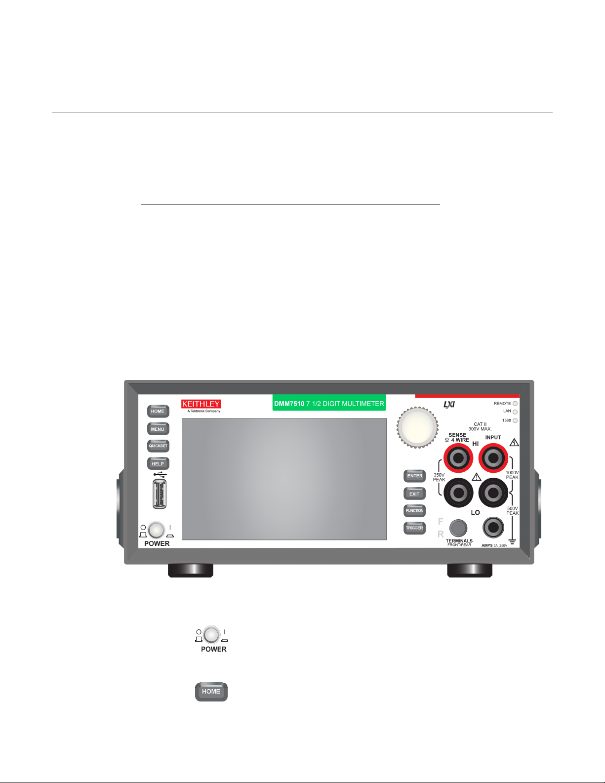
Front-panel overview
The front panel of the Model DMM7510 is shown below. Descriptions of the controls on the front
panel follow the figure.
Section 2
Using the front-panel interface
Figure 1: Model DMM7510 front panel
POWER switch
the power switch so that it is in the on position (|). To turn it off,
HOME key
Page 15
Section
User's Manual
Opens the main menu. Press the icons on the main menu to open
Opens a menu of preconfigured setups, including Voltage
Setups.
Opens help for the area or item that is selected on the display. If
overview information for the screen you are viewing.
The Model DMM7510 has a high-resolution, five-inch color
keys. Refer to Touchscreen display (on page 2-5) for details.
Moves the cursor and make screen selections.
Selects the highlighted choice
or allows you to edit the selected field.
Selects the highlighted choice or allows you to edit the selected
field.
to the main menu screen.
Displays instrument functions. To select a function, touch the
function name on the screen.
2: Using the front-panel interface Model DMM7510 7½ Digit Multimeter
MENU key
measure, view, trigger, script, and sy stem scree ns. For det ai l s,
refer to Menu overview (on page 2-13).
QUICKSET key
Waveform, Interval Measure, Current Waveform, and External
Scan. Also allows you to choose measure functions and adjust
performance for better resolution or speed. Refer to Using Quick
HELP key
there is no selection when you press the HELP key, it displays
USB port
Saves reading buffer data and screen snapshots to a USB flash
drive. Also stores and retrieves scripts to and from a USB flash
drive. The flash drive must be formatted as a FAT drive.
Touchscreen
touchscreen display. The touchscreen accesses swipe screens
and menu options. You can access additional interactive screens
by pressing the front-panel MENU, QUICKSET, and FUNCTION
Navigation control
ENTER key
EXIT key
FUNCTION key
Turning the navigation control: Moves the cursor to highlight a
list value or menu item so that you can select it. Turning the
control when the cursor is in a value entry field increases or
decreases the value in the field.
Pressing the navigation control:
Returns to the previous screen or closes a dialog box. For
example, press the EXIT key when the main menu is displayed to
return to the Home screen. When you are viewing a subscreen
(for example, the Event Log screen), press the EXIT key to return
2-2 DMM7510-900-01 Rev. B / May 2015
Page 16
Model DMM7510
Accesses trigger-related settings and operations. The action of
the TRIGGER key depends on the instrument state.
Illuminates when the instrument is connected to a local area network
Use the SENSE HI and SENSE LO terminals and the INPUT
INPUT terminals
Use the INPUT HI and INPUT LO terminals for all measurements
AMPS
Use the AMPS connection with the INPUT LO terminal to measure
7½ Digit Multimeter User's Manual Section 2: Using the front-panel interface
TRIGGER key
REMOTE LED
indicator
Illuminates when the instrument is controlled through a remote
interface.
LAN LED indicator
(LAN).
1588 LED indicator
Illuminates when the instrument is connected to an IEEE-1588
compliant device.
1588 functionality is not supported at this time. This functionality will be made available with a
firmware update. See the Model DMM7510 Release Notes on the Keithley Instruments website
(http://www.keithley.com) for details.
SENSE terminals
terminals with the 4-wire resistance, 3-wire and 4-wire RTD
temperature, and DC voltage ratio functions.
except current.
≤3A DC or AC
DMM7510-900-01 Rev. B / May 2015 2-3
current.
rms
Page 17
Section
User's Manual
Activates the terminals on the front or rear panel. When the
active, a yellow "R" is visible to the left of the switch.
2: Using the front-panel interface Model DMM7510 7½ Digit Multimeter
FRONT/REAR
TERMINALS switch
Instrument power
Follow the steps below to connect the Model DMM7510 to line power and turn on the instrument. The
Model DMM7510 operates from a line voltage of 100 V to 240 V at a frequency of 50 Hz or 60 Hz. It
automatically senses line voltage and frequency. Make sure the operating voltage in your area is
compatible.
You must turn on the Model DMM7510 and allow it to warm up for at least 90 minutes to achieve
rated accuracies.
Operating the instrument on an incorrect line voltage may cause damage to the instrument, possibly
voiding the warranty.
The power cord supplied with the Model DMM7510 contains a separate protective earth
(safety ground) wire for use with grounded outlets. When proper connections are made, the
instrument chassis is connected to power-line ground through the ground wire in the power
cord. In the event of a failure, not using a properly grounded protective earth and grounded
outlet may result in personal injury or death due to electric shock.
front-panel terminals are active, a green "F" is visible to the left of
the FRONT/REAR switch. When the rear-panel terminals are
Do not replace detachable mains supply cords with inadequately rated cords. Failure to use
properly rated cords may result in personal injury or death due to electric shock.
Connect the power cord
To connect the power cord:
1. Make sure that the front-panel POWER switch is in the off (O) position.
2. Connect the female end of the supplied power cord to the AC receptacle on the rear panel.
3. Connect the other end of the power cord to a grounded AC outlet.
Turn the Model DMM7510 on or off
To turn a Model DMM7510 on:
1. Disconnect any devices under test (DUTs) from the Model DMM7510.
2. Press the front-panel POWER switch to place it in the on (|) position.
The instrument displays a status bar as the instrument powers on. The Home screen is displayed
when power on is complete.
To turn a Model DMM7510 off:
1. Press the front-panel POWER switch to place it in the off (O) position.
2-4 DMM7510-900-01 Rev. B / May 2015
Page 18
Model DMM7510
7½ Digit Multimeter User's Manual Section 2: Using the front-panel interface
Touchscreen display
The touchscreen display gives you quick front-panel access to measure settings, system
configuration, instrument and test status, reading buffer information, and other instrument
functionality. The display has multiple swipe screens that you can access by swiping the front panel.
You can access additional interactive screens by pressing the front-panel MENU, QUICKSET, and
FUNCTION keys.
Do not use sharp metal objects, such as tweezers or screwdrivers, or pointed objects, such as pens
or pencils, to touch the touchscreen. It is strongly recommended that you use only fingers to operate
the instrument. Use of clean-room gloves to operate the touchscreen is supported.
The following topics describe the features of the touchscreen in more detail.
Select items on the touchscreen
To select an item on the displayed screen, do one of the following:
• Touch it with your finger
• Turn the navigation control to highlight the item, and then press the navigation control to select it
The following topics describe the Model DMM7510 touchscreen in more detail.
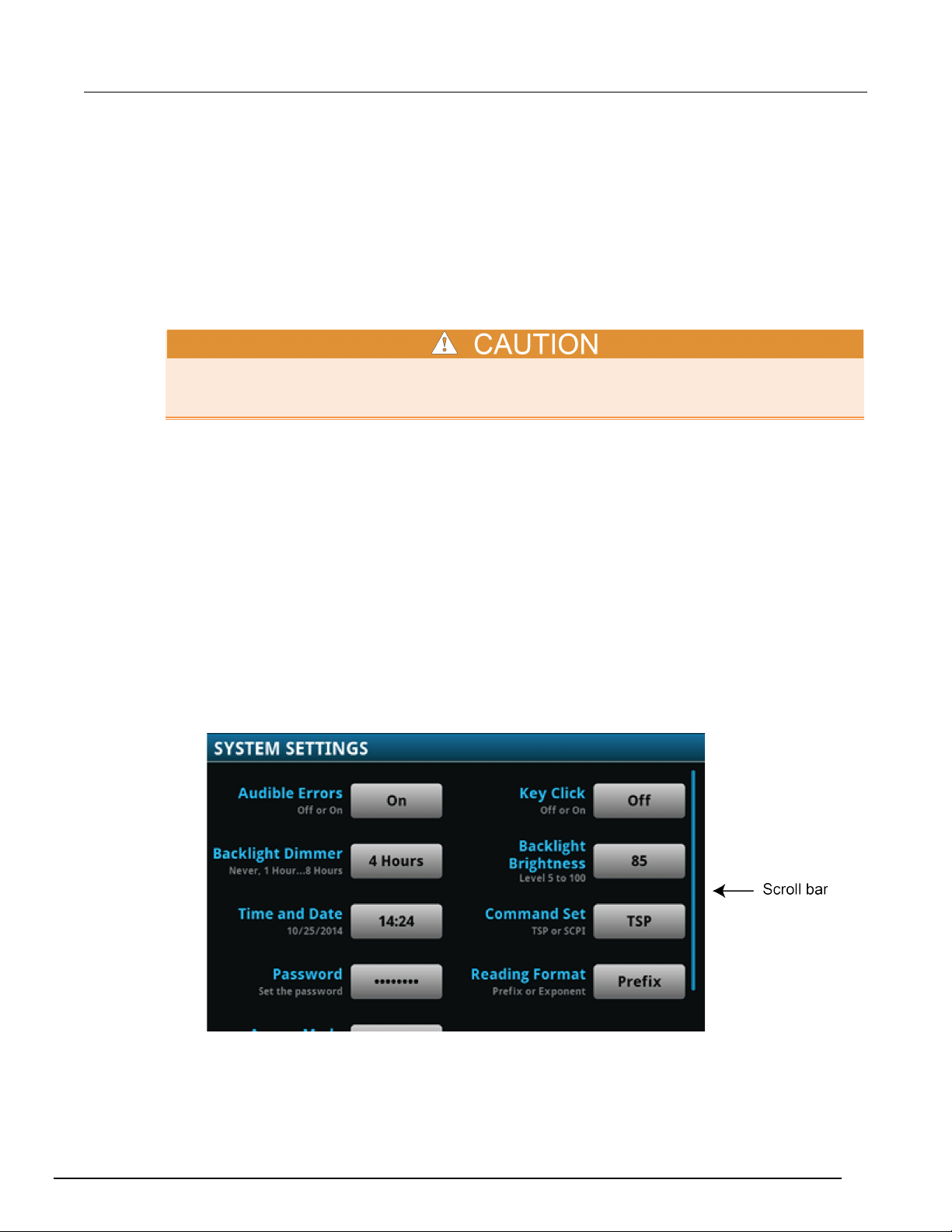
Scroll bars
Some of the interactive screens have additional options that are only visible when you scroll down the
screen. A scroll indicator on the right side of the touchscreen identifies these screens. Swipe the
screen up or down to view the additional options.
The figure below shows a screen with a scroll bar.
DMM7510-900-01 Rev. B / May 2015 2-5
Page 19
Section
User's Manual
2: Using the front-panel interface Model DMM7510 7½ Digit Multimeter
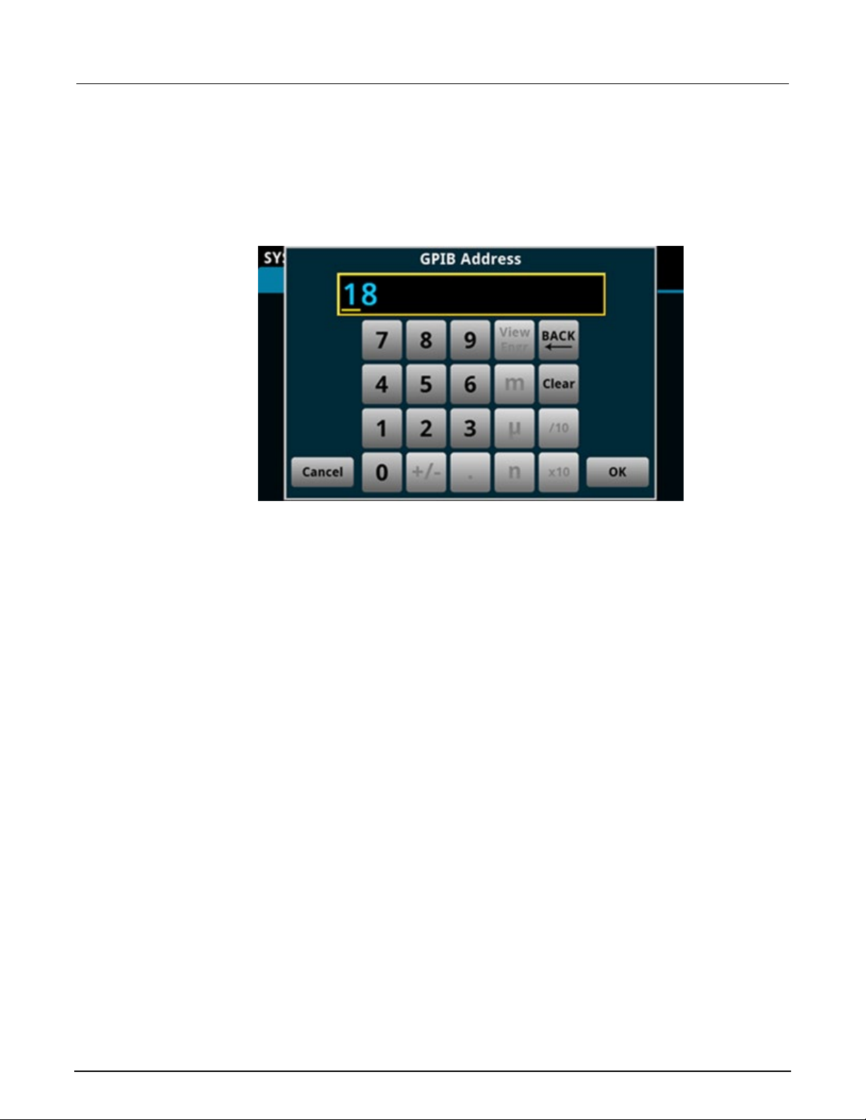
Enter information
Some of the menu options open a keypad or keyboard that you can use to enter information. For
example, if you are setting the GPIB address from the front panel, you see the keypad shown in the
following figure.
Figure 2: Front-panel keyboard for GPIB Address entry
You can enter information by touching the screen to select characters and options from the keypad or
keyboard. You can move the cursor in the entry box by touching the screen. The cursor is moved to
the spot in the entry box where you touched the screen. On number keypads, you can also use the
navigation control to move the cursor to a specific number.
On number keypads, you can use the navigation control to set values:
1. Turn the control to underline the character that you want to change.
2. Press the control to select the character for edit.
3. Turn the control to scroll through the options.
4. Press the control to set the character.
5. Press the ENTER key to save the change.
On keyboards and keypads, you can use the navigation control to select characters.
2-6 DMM7510-900-01 Rev. B / May 2015
Page 20
Model DMM7510
7½ Digit Multimeter User's Manual Section 2: Using the front-panel interface
Adjust the backlight brightne s s and dim m er
You can adjust the brightness of the Model DMM7510 touchscreen display and buttons from the front
panel or over a remote interface. You can also set the backlight to dim after a specified time has
passed with no front-panel activity (available from the front-panel display only). The backlight settings
set through the front-panel display are saved through a reset or power cycle.
Screen life is affected by how long the screen is on at full brightness. The higher the brightness
setting and the longer the screen is bright, the shorter the screen life.
To adjust the backlight brightness from the front panel:
1. Press the MENU key.
2. Under System, select Settings.
3. Select the button next to Backlight Brightness. The Backlight Brightness dialog box opens.
4. Drag the sliding adjustment to set the backlight.
5. Select OK to save your setting.
To set the backlight dimmer from the front panel:
1. Press the MENU key.
2. Under System, select Settings.
3. Select the button next to Backlight Dimmer. The Backlight Dimmer dialog box opens.
4. Select a dimmer setting.
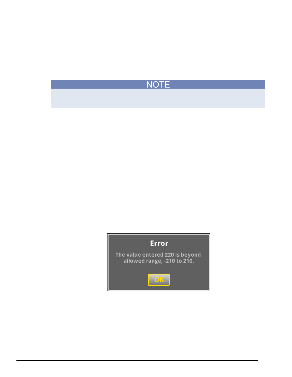
Review event messages
During operation and programming, front-panel messages may be briefly displayed. Messages are
either information, warning, or error notifications. For information on event messages, refer to "Using
the event log" in the Model DMM7510 Reference Man ual.
Figure 3: Example front-panel event message
Interactive swipe screens
The Model DMM7510 touchscreen display has multiple screens that you can access by gently
swiping left or right on the lower half of the display. The options available in the swipe screens are
described in the following topics.
DMM7510-900-01 Rev. B / May 2015 2-7
Page 21
Section
User's Manual
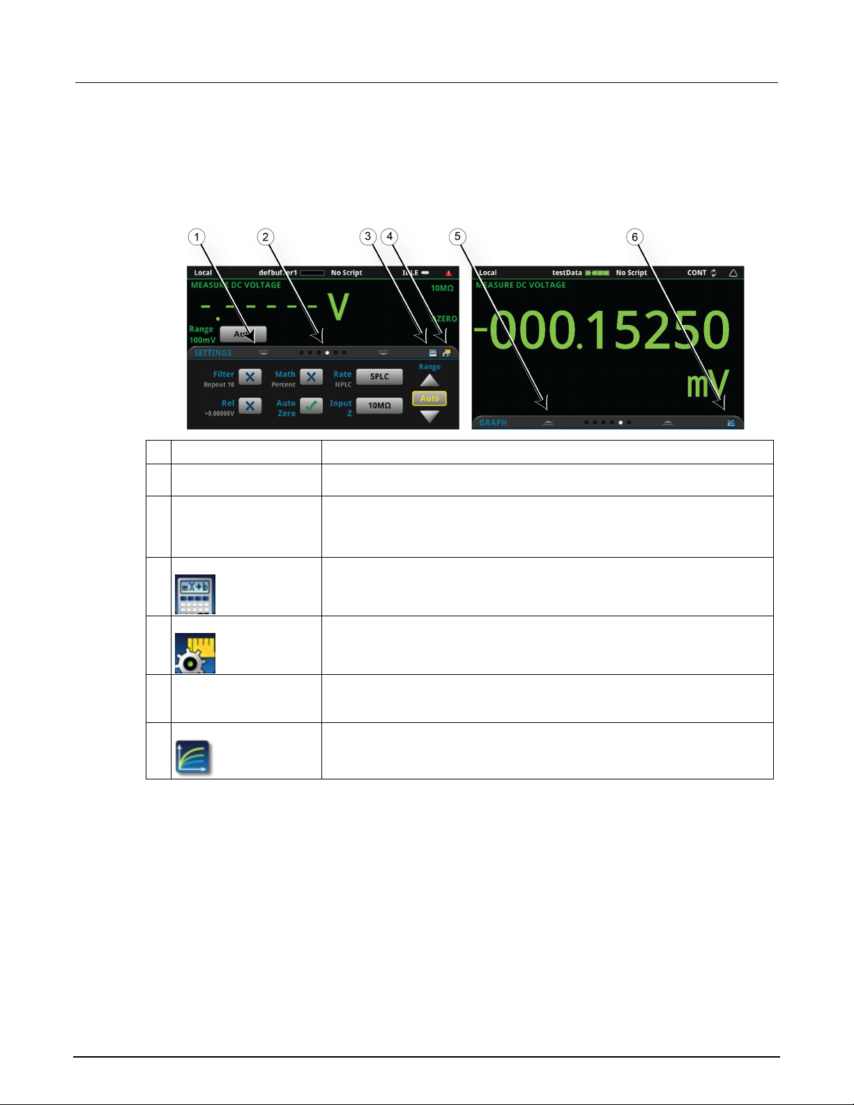
circle changes color, indicating where you are in the screen sequence. Select a
5
Restore indicator
Indicates that you can swipe up to display the swipe screen.
6
Graph shortcut
Select to open the Graph screen.
2: Using the front-panel interface Model DMM7510 7½ Digit Multimeter
Swipe screen heading bar
The heading bar of the swipe screen contains the following options.
Figure 4: Model DMM7510 swipe screens, maximized and minimized
# Screen element Description
1 Minimize indicator You can swipe down to minimize the swipe screens.
2 Swipe screen indicator Each circle represents one swipe screen. As you swipe right or left, a different
circle to go to a swipe screen without swiping.
3 Calculations shortcut
4 Settings shortcut
Select to open the CALCULATIONS SETTINGS menu.
Select to open the MEASURE SETTINGS menu for the selected function.
2-8 DMM7510-900-01 Rev. B / May 2015
Page 22
Model DMM7510
7½ Digit Multimeter User's Manual Section 2: Using the front-panel interface
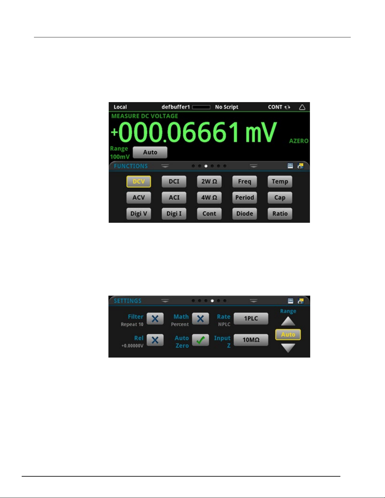
FUNCTIONS swipe screen
The FUNCTIONS swipe screen highlights the selected measure function and allows you to select a
different function.
Figure 5: FUNCTIONS swipe screen
SETTINGS swipe screen
The SETTINGS swipe screen gives you front-panel access to some instrument settings for the
selected measure function. It shows you the present settings and allows you to change them. The
available settings depend on which measure function is active.
Figure 6: SETTINGS swipe screen
To disable or enable a setting, select the box next to the setting so that it shows an X (disabled) or a
check mark (enabled).
For descriptions of the settings, use the navigation control to select a button, then press the HELP
key.
DMM7510-900-01 Rev. B / May 2015 2-9
Page 23
Section
User's Manual
2: Using the front-panel interface Model DMM7510 7½ Digit Multimeter
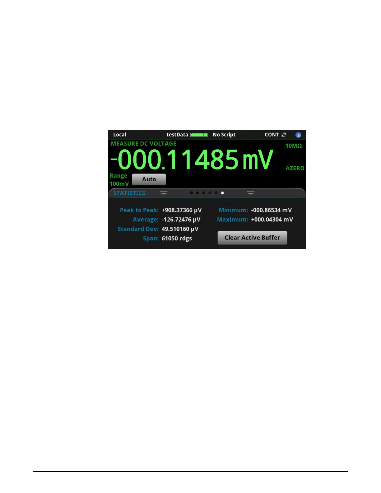
STATISTICS swipe screen
The STATISTICS swipe screen contains information about the readings in the active reading buffer.
When the reading buffer is configured to fill continuously and overwrite older data with new data, the
buffer statistics include the data that was overwritten. To get statistics that do not include data that
has been overwritten, define a large buffer size that will accommodate the number of readings you
will make. You can use the Clear Active Buffer button on this screen to clear the data from the
active reading buffer.
Figure 7: STATISTICS swipe screen
2-10 DMM7510-900-01 Rev. B / May 2015
Page 24
Model DMM7510
7½ Digit Multimeter User's Manual Section 2: Using the front-panel interface
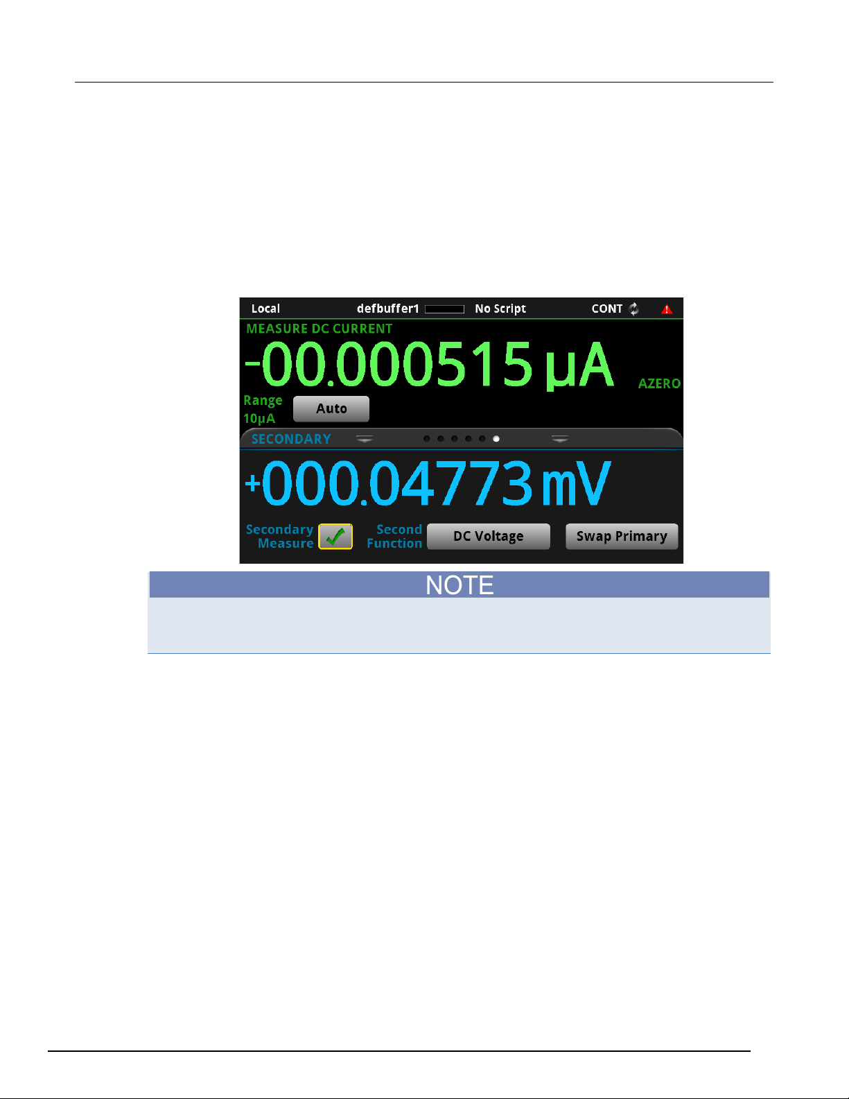
SECONDARY swipe screen
The SECONDARY swipe screen allows you to display the results of two measurements on the
front-panel display.
To start displaying secondary measurements, select the Second Function and select Secondary
Measure. Secondary measurements are only available in Continuous Measurement Mode and
Manual Trigger Mode. Refer to "Display results of two measure functions" in the Model DMM7510
Reference Manual.
Figure 8: SECONDARY swipe screen
Depending on the selected functions, a relay may click when the instrument switches between the
measurement types. Leaving secondary measurements on for extended periods may shorten the life
of the relays.
DMM7510-900-01 Rev. B / May 2015 2-11
Page 25
Section
User's Manual
2: Using the front-panel interface Model DMM7510 7½ Digit Multimeter
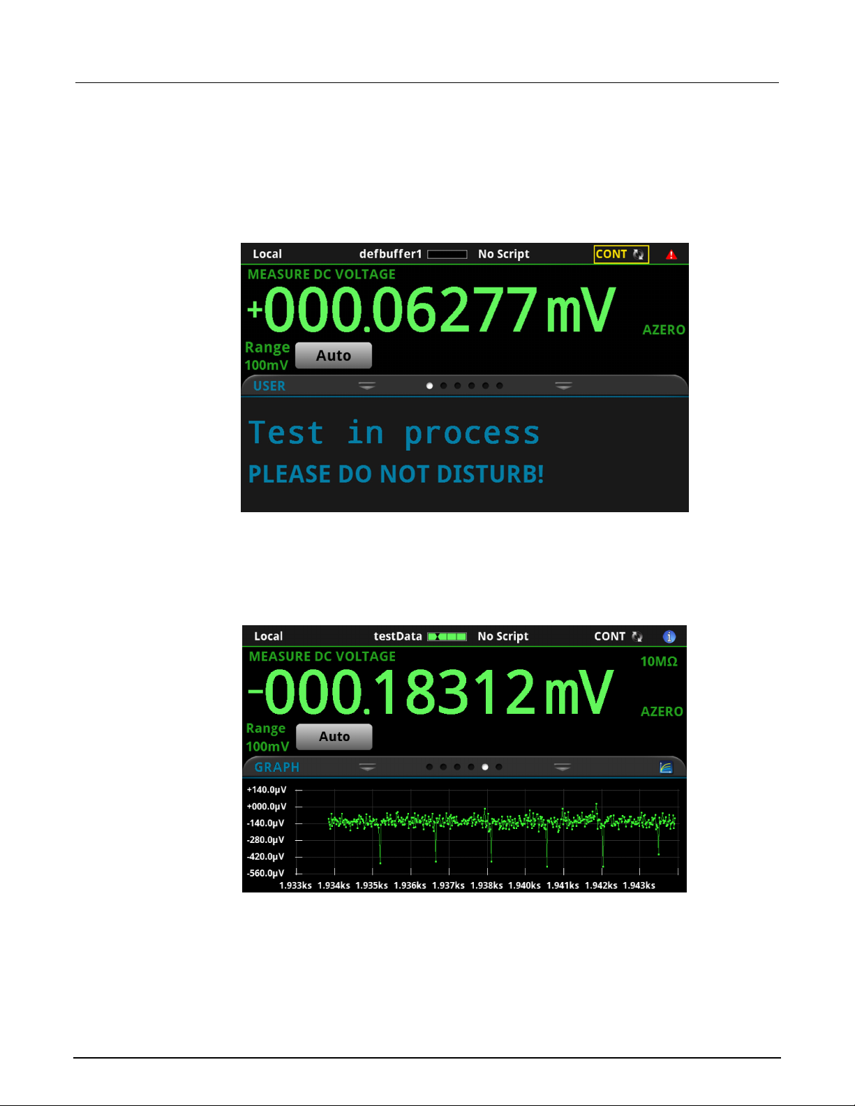
USER swipe screen
You can program custom text that appears on the USER swipe screen. For example, you can
program the Model DMM7510 to show that a test is in process. Refer to "Customizing a message for
the USER swipe screen" in the Model DMM7510 Reference Manual.
Figure 9: USER swipe screen
GRAPH swipe screen
The GRAPH swipe screen shows a graphical representation of the readings in the presently selected
reading buffer.
Figure 10: GRAPH swipe screen
To view the graph in the full screen and to access graph settings, select the graph icon on the right
side of the swipe screen header. You can also open the full-function Graph screen by pressing the
MENU key and selecting Graph un der Vi e ws.
For more information about graphing measurements, see "Graphing" in the Model D MM7510
Reference Manual.
2-12 DMM7510-900-01 Rev. B / May 2015
Page 26
Model DMM7510
7½ Digit Multimeter User's Manual Section 2: Using the front-panel interface
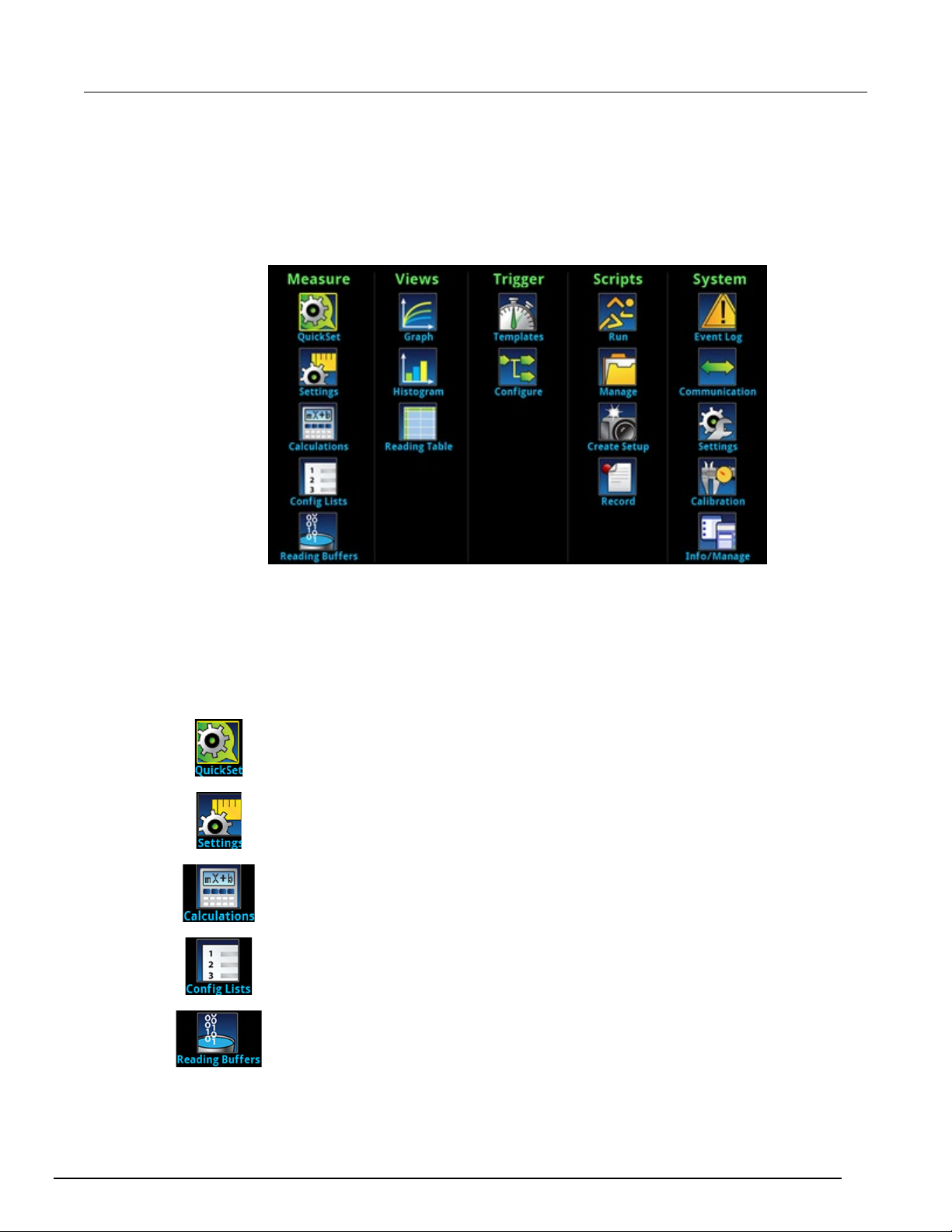
Menu overview
To access the main menu, press the MENU key on the Model DMM7510 front panel. The figure
below shows the organization of the main menu.
Figure 11: Model DMM7510 main menu
The main menu includes submenus that are labeled in green across the top of the display. Touching
an icon in a submenu opens an interactive screen.
Measure menu
The Measure menus allow you to select, configure, and perform measure operations from the front
panel.
The QuickSet icon at the top left of the main menu allows you to change the
function, adjust performance, and set quick-setup options. You can also access the
QuickSet menu by pressing the QUICKSET key on the front panel.
The Measure Settings menu contains settings for the presently selected measure
function, which is identified by the function indicator in the upper right corner of the
menu. The available settings depend on the front-panel FUNCTION key selection.
The Calculations menu contains settings that specify the way measurement
information is processed and returned.
The Config Lists menu allows you to select an existing measure configuration list,
create a new list, load configuration settings to and from the instrument (system),
and view the settings of an index in a configuration list.
DMM7510-900-01 Rev. B / May 2015 2-13
The Reading Buffers menu allows you to view the list of existing reading buffers
and select one to be the active buffer. You can also create, save, delete, resize,
and clear buffers from this screen.
Page 27
Section
User's Manual
2: Using the front-panel interface Model DMM7510 7½ Digit Multimeter
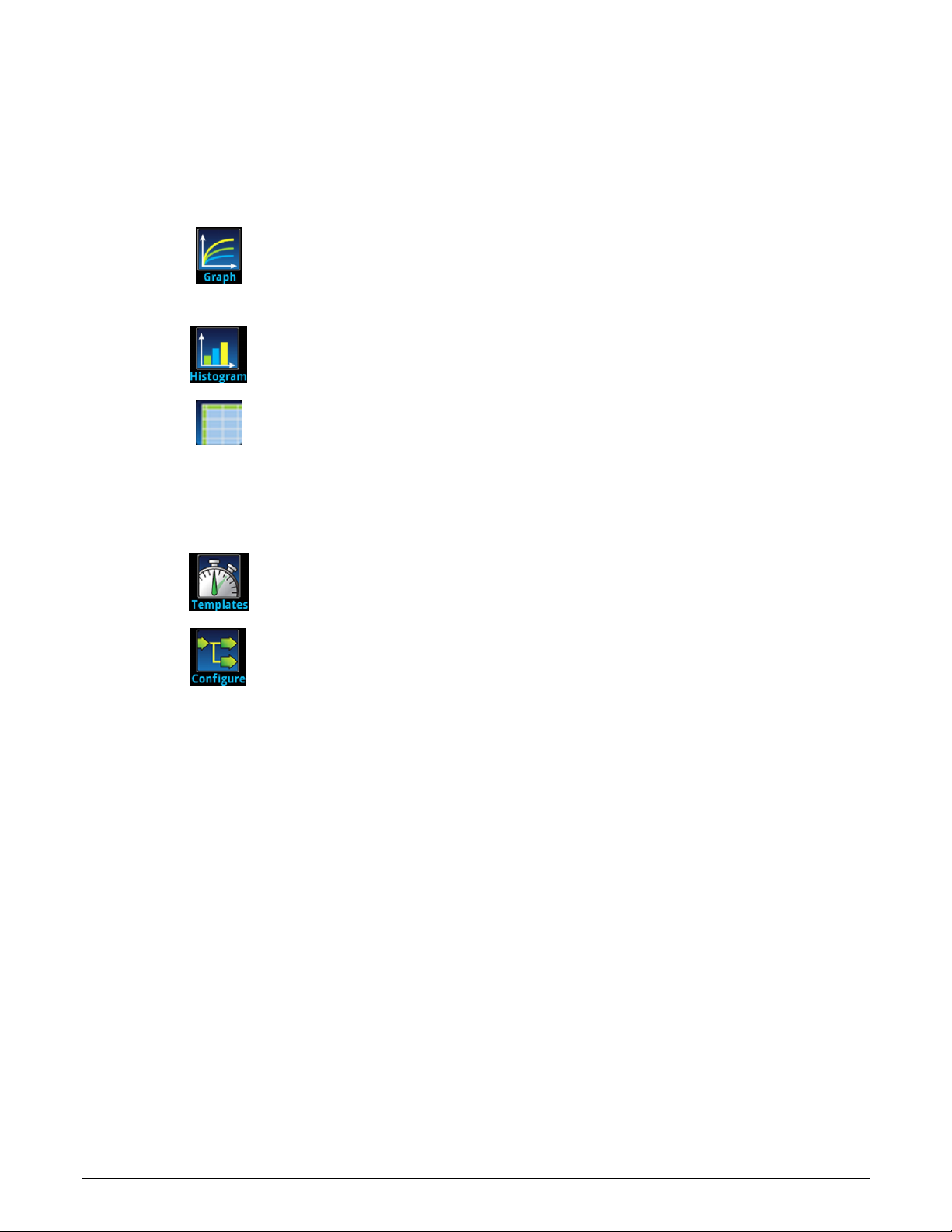
Views menu
The Views menus allow you to select, configure, and view data that was gathered from measure
operations.
The Graph m enu opens a sc reen that displays a graph of the measurements in
selected reading buffers as traces. It also contains tabs that you use to customize
the graph display.
You can also select the trigger mode and initiate the trigger model from this screen.
The Histogram menu allows you to graph the distribution of measurement data in
the selected reading buffer. It also contains tabs that you use to customize the
histogram.
The Reading Table menu allows you to view data in the selected reading buffer.
Trigger menu
The Trigger menus allow you to configure the trigger model from the front panel.
The Templates menu allows you to choose from one of several preprogrammed
trigger models. When you select a template, settings you can specify for that
template are shown in the lower part of the screen.
The Configure menu allows you to see and modify the structure and parameters of
a trigger model. You can also monitor trigger model operation.
2-14 DMM7510-900-01 Rev. B / May 2015
Page 28
Model DMM7510
7½ Digit Multimeter User's Manual Section 2: Using the front-panel interface
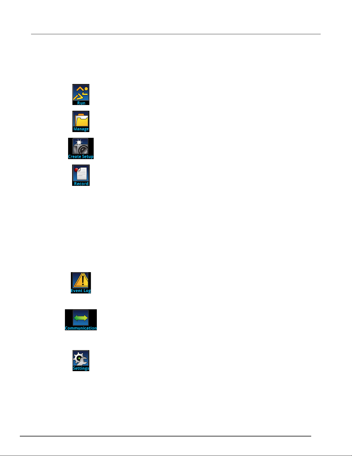
Scripts menu
The Scripts menus allow you to configure, run, and manage scripts from the front panel. Scripts are
blocks of commands that the instrument can run as a group.
The Run menu contains a list of scripts that you can select to run immediately. You
can also copy a script to a script that runs each time the instrument power is turned
on. You can access scripts that are in the instrument or on a USB flash drive.
The Manage menu allows you to copy scripts to and from the instrument and the
USB flash drive. You can also delete scripts from the instrument or USB flash drive.
The Create Setup menu allows you to save the present settings and configuration
lists of the instrument into a configuration script. You can use this script to recall the
settings.
The options in the Record menu allow you to record your actions and store them in
a macro script. The script can be run and managed like any other script using the
options in the Scripts menu or remote commands. Note that only settings are
stored; no key presses or front-panel only options are stored (including pressing the
OUTPUT ON/OFF switch).
System menu
The menus under System in the main menu allow you to configure general instrument settings from
the Model DMM7510 front panel. Among these settings are the event log, communications, backlight,
time, and password settings.
The following topics describe the settings that are available on these interactive screens.
The Event Log menu allows you to view and clear event log entries. You can also
adjust which events are displayed or logged.
The Communication menu opens a set of tabs that contain information about the
Model DMM7510 communications settings. Most of the tabs contain settings that
you can change.
The Settings menu contains general instrument settings. It includes beeper and
key click, backlight brightness and timer, time and date, system access level,
password, and reading format settings.
DMM7510-900-01 Rev. B / May 2015 2-15
Page 29

Section
ser's Manual
2: Using the front-panel interface Model DMM7510 7½ Digit Multimeter U
The Calibration menu allows you to start or manage auto calibration. Auto
calibration removes measurement errors that are caused by the effects of
temperature and time on components. You can also review factory adjustment and
verification dates.
The Info/Manage menu gives you access to version and serial number information
and settings for instrument firmware and reset functions.
2-16 DMM7510-900-01 Rev. B / May 2015
Page 30

Determining the command set you will use ............................ 3-14
In this section:
Remote communications interfaces.......................................... 3-1
Supported remote interfaces .................................................... 3-2
GPIB communications .............................................................. 3-2
LAN communications................................................................ 3-5
USB communications ............................................................... 3-7
Using the web interface .......................................................... 3-11
Remote communications interfaces
Section 3
Using a remote int er f ace
You can choose from one of several communication interfaces to send commands to and receive
responses from the Model DMM7510.
You can control the Model DMM7510 from only one communications interface at a time. The first
interface on which it receives a message takes control of the instrument. If another interface sends a
message, that interface can take control of the instrument. You may need to enter a password to
change the interface, depending on the access mode.
The Model DMM7510 automatically detects the type of communications interface (LAN, GPIB, or
USB) when you connect to the respective port on the rear panel of the instrument. In most cases, you
do not need to configure anything on the instrument. In addition, you do not need to reboot if you
change the type of interface that is connected.
Page 31

Section
User's Manual
3: Using a remote interface Model DMM7510 7½ Digit Multimeter
Supported remote interfaces
The Model DMM7510 supports the following remote interfaces:
• GPIB: IEEE-488 instrumentation general purpose interface bus
• Ethernet: Local area network ethernet communications
• USB: Type B USB port
• TSP-Link: A high-speed trigger synchronization and communications bus that test system
builders can use to connect multiple instruments in a master-and-subordinate configuration
For details about TSP-Link, see "TSP-Link System Expansion Interface" in the Model DMM7510
Reference Manual.
The rear panel connections for the remote communication interfaces are shown in the following
figure.
Figure 12: Model DMM7510 remote interface connections
GPIB communications
The Model DMM7510 GPIB interface is IEEE Std 488.1 compliant and supports IEEE Std 488.2
common commands and status model topology.
You can have up to 15 devices connected to a GPIB interface, including the controller. The maximum
cable length is the lesser of either:
• The number of devices multiplied by 2 m (6.5 ft)
• 20 m (65.6 ft)
You may see erratic bus operation if you ignore these limits.
3-2 DMM7510-900-01 Rev. B / May 2015
Page 32

Model DMM7510
Using a remote interface
7½ Digit Multimeter User's Manual Section 3:
Install the GPIB driver software
Check the documentation for your GPIB controller for information about where to acquire drivers.
Keithley Instruments also recommends that you check the website of the GPIB controller for the latest
version of drivers or software.
It is important that you install the drivers before you connect the hardware. This prevents associating
the incorrect driver to the hardware.
Install the GPIB cards in your computer
Refer to the documentation from the GPIB controller vendor for information about installing the GPIB
controllers.
Connect GPIB cables to your ins tr um e nt
To connect an instrument to the GPIB interface, use a cable equipped with standard GPIB
connectors, as shown below.
Figure 13: GPIB connector
DMM7510-900-01 Rev. B / May 2015 3-3
To allow many parallel connections to one instrument, stack the connectors. Each connector has two
screws to ensure that connections remain secure. The figure below shows a typical connection
diagram for a test system with multiple instruments.
To avoid possible mechanical damage, stack no more than three connectors on any one instrument.
To minimize interference caused by electromagnetic radiation, use only shielded GPIB cables.
Contact Keithley Instruments for shielded cables.
Page 33

Section
User's Manual
3: Using a remote interface Model DMM7510 7½ Digit Multimeter
Figure 14: Instrument GPIB conne ctions
Set the GPIB address
The default GPIB address is 16. You can set the address to any address from 1 to 30 if it is unique in
the system. This address cannot conflict with an address that is assigned to another instrument or to
the GPIB controller.
GPIB controllers are usually set to 0 or 21. To be safe, do not configure any instrument to have an
address of 21. To change the controller address, see the documentation for the controller.
The instrument saves the address in nonvolatile memory. It does not change when you send a reset
command or when you turn the power off and then on again.
To set the GPIB address from the front panel:
1. Press the MENU key.
2. Under System, select Communication. The SYSTEM COMMUNICATIONS window opens.
3. Select the GPIB tab.
4. Next to Address, select the number. The GPIB Address dialog box is displayed.
5. Enter the address.
6. Select OK.
3-4 DMM7510-900-01 Rev. B / May 2015
Page 34

Model DMM7510
Using a remote interface
7½ Digit Multimeter User's Manual Section 3:
LAN communications
You can communicate with the instrument using a local area network (LAN).
When you connect using a LAN, you can use a web browser to access the internal web page of the
instrument and change some of the instrument settings. For more information, see Using the web
interface (on page 3-11).
The Model DMM7510 is an LXI version 1.4 Core 2011 compliant instrument that supports TCP/IP and
complies with IE EE Std 802.3 (ethernet LAN). There is one LAN port (located on the rear panel of the
instrument) that supports full connectivity on a 10 Mbps or 100 Mbps network. The Model DMM7510
automatically detects the speed.
The Model DMM7510 also supports Multicast DNS (mDNS) and DNS Service Discovery (DNS-SD),
which are useful on a LAN with no central administr at i on.
Contact your network administrator to confirm your specific network requirements before setting up a
LAN connection.
If you have problems setting up the LAN, refer to LAN troubleshooting suggestions (on page 3-12).
Set up LAN communications on t he instrument
This section describes how to set up manual or automatic LAN communications on the instrument.
Check communication settings
Before setting up the LAN configuration, you can check the communication settings on the instrument
without making any changes.
To check communication settings on the instrument:
1. Press the MENU key.
2. Under System, select Communication. The SYSTEM COMMUNICATIONS windo w opens .
3. Select one of the four tabs, GPIB, USB, LAN, or TSP-Link, to see the settings for that interface.
4. Press the EXIT key to leave the SYSTEM COMMUNICATION window without making any
changes.
Set up automatic LAN configuration
If you are connecting to a LAN that has a DHCP server or if you have a direct connection between the
instrument and a host computer, you can use automatic IP address selection.
If you select Auto, the instrument attempts to get an IP address from a DHCP server. If this fails, it
reverts to an IP address in the range of 169.254.1.0 through 169.254.254.255.
Both the host computer and the instrument should be set to use automatic LAN configuration.
Though it is possible to have one set to manual configuration, it is more complicated to set up.
DMM7510-900-01 Rev. B / May 2015 3-5
Page 35

Section
User's Manual
3: Using a remote interface Model DMM7510 7½ Digit Multimeter
To set up automatic IP address selection using the front panel:
1. Press the MENU key.
2. Under System, select Communication.
3. Select the LAN tab.
4. For TCP/IP Mode, select Auto.
5. Select Apply Settings to save your settings.
Set up manual LAN configuration
If necessary, you can set the IP address on the instrument manually.
You can also enable or disable the DNS settings and assign a host name to the DNS server.
Contact your corporate information technology (IT) department to secure a valid IP address for the
instrument when placing the instrument on a corporate network.
The instrument IP address has leading zeros, but the computer IP address cannot.
To set up manual IP address selection on the instrument:
1. Press the MENU key.
2. Under System, select Communication.
3. Select the LAN tab.
4. For TCP/IP Mode, select Manual.
5. For IP Address, enter the LAN IP address. You can touch the number you want to change.
6. For Gateway, enter the gateway address.
7. For Subnet, enter the subnet mask.
8. Select Apply Settings to save your settings.
Set up LAN communications on t he computer
This section describes how to set up the LAN communications on your computer.
Do not change your IP address without consulting your system administrator. If you enter an
incorrect IP address, it can prevent your computer from connecting to your corporate network or it
may cause interference with another networked computer.
Record all network configurations before modifying any existing network configuration information on
the network interface card. Once the network configuration settings are updated, the previous
information is lost. This may cause a problem reconnecting the host computer to a corporate
network, particularly if DHCP is disabled.
Be sure to return all settings to their original configuration before reconnecting the host computer to a
corporate network. Contact your system administrator for more information.
Wait for the LAN status indicator on the front panel to turn solid green
A solid green LAN status indicator confirms that the instrument was assigned an IP address. Note
that it may take several minutes for the computer and instrument to establish a connection.
3-6 DMM7510-900-01 Rev. B / May 2015
Page 36

Model DMM7510
Using a remote interface
7½ Digit Multimeter User's Manual Section 3:
Install LXI Discovery Browser software on your computer
You can use the LXI Discovery Browser to identify the IP addresses of LXI-certified instruments.
Once identified, you can double-click the IP address in the LXI Discovery Browser to open the web
interface for the instrument.
The Keithley LXI Discovery Browser is available on the Keithley Instruments website
(http://www.keithley.com).
To locate the Keithley LXI Discovery Browser on the Keithley website:
1. Select the Support tab.
2. In the model number box, type DMM7510.
3. From the list, select Software and click the search icon. A list of software applications for the
instrument is displayed.
4. See the readme file included with the application for more information.
For more information about the LXI Consortium, see the LXI Consortium website
(http://www.lxistandard.org/).
Run the LXI Discovery Browser
To run the LXI Discovery Browser software:
1. From the Microsoft Windows Start menu, select Keithley Instruments.
2. Select LXI Discovery Browser.
3. Click LXI Discovery Browser. The Keithley LXI Discovery Browser window is displayed.
The LXI Discovery Browser displays the instruments that it finds on the network and their
associated IP addresses.
4. Double-click an IP address in the LXI Discovery Browser dialog box. The instrument web page for
that instrument opens.
For information about using the web page, refer to Using the web interface.
USB communications
To use the rear-panel USB port, you must have the Virtual Instrument Software Architecture (VISA)
layer on the host computer. See "How to install the Keithley I/O Layer" in the Model DMM7510
Reference Manual for more information.
VISA contains a USB-class driver for the USB Test and Measurement Class (USBTMC) protocol that,
once installed, allows the Microsoft
When you connect a USB device that implements the USBTMC or USBTMC-USB488 protocol to the
computer, the VISA driver automatically detects the device. Note that the VISA driver only
automatically recognizes USBTMC and USBTMC-USB488 devices. It does not recognize other USB
devices, such as printers, scanners, and storage devices.
In this section, "USB instruments" refers to devices that implement the USBTMC or
USBTMC-USB488 protoc o l .
®
Windows® operating system to recognize the instrument.
DMM7510-900-01 Rev. B / May 2015 3-7
Page 37

Section
er's Manual
3: Using a remote interface Model DMM7510 7½ Digit Multimeter Us
Connect a computer to the Model DMM75 1 0 using USB
To connect the Model DMM7510 to a computer using a USB connection, use Keithley Instruments
Model USB-B-1, which is shipped with the instrument.
Each Model DMM7510 needs its own USB cable to be connected to the computer.
To connect an instrument to a computer using USB:
1. Connect the Type A end of the cable to the computer.
2. Connect the Type B end of the cable to the instrument.
3. Turn on the instrument power. When the computer detects the new USB connection, the Found
New Hardware Wizard starts.
4. If the "Can Windows connect to Windows Update to search for software?" dialog box opens, click
No, and then click Next.
5. On the "USB Test and Measurement device" dialog box, click Next, and then click Finish.
Communicate with the ins tr um e nt
For the instrument to communicate with the USB device, you must use NI-VISATM. VISA requires a
resource string in the following format to connect to the correct USB instrument:
USB0::0x05e6::0x7510::[serial number]::INSTR
Where:
• 0x05e6: The Keithley vendor ID
• 0x7510: The instrument model number
• [serial number]: The serial number of the instrument (the serial number is also on the rear
panel)
• INSTR: Use the USBTMC protocol
To determine these parameters, you can run the Keithley Configuration Panel, which automatically
detects all instruments connected to the computer.
If you installed the Keithley I/O La yer, you can access the Keithley Configuration Panel through the
Microsoft
®
Windows® Start menu.
3-8 DMM7510-900-01 Rev. B / May 2015
Page 38

Model DMM7510
Using a remote interface
7½ Digit Multimeter User's Manual Section 3:
To use the Keithley Configuration Panel to determine the VISA resource string:
1. Click Start > All Programs > Keithley Instruments > Keithley Configuration Panel. The
Select Operation dialog box is displayed.
Figure 15: Select Operation dia log box
2. Select Add.
3. Click Next. The Select Communication Bus dialog box is displayed.
Figure 16: Select Communication Bus dialog box
4. Select USB.
5. Click Next. The Select Instrument Driver dialog box is displayed.
DMM7510-900-01 Rev. B / May 2015 3-9
Page 39

Section
User's Manual
3: Using a remote interface Model DMM7510 7½ Digit Multimeter
Figure 17: Select Instrument Driver dialog box
6. Select Auto-detect Instrument Driver - Model.
7. Click Next. The Configure USB Instrument dialog box is displayed with the detected instrument
VISA resource string visible.
8. Click Next. The Name Virtual Instrument dialog box is displayed.
Figure 18: Name Virtual Instrum ent dialog box
9. In the Virtual Instrument Name box, enter a name that you want to use to refer to the instrument.
10. Click Finish.
11. Click Cancel to close the Wizard.
3-10 DMM7510-900-01 Rev. B / May 2015
12. Save the configuration. From the Keithley Configuration Panel, select File > Save.
Page 40

Model DMM7510
Using a remote interface
7½ Digit Multimeter User's Manual Section 3:
Verify the instrument through the Keithley Communicator:
1. Click Start > All Programs > Keithley Instruments > Keithley Communicator.
2. Select File > Open Instrument to open the instrument you just named.
Figure 19: Keithley Communica to r Open an Instrument
3. Click OK.
4. Send a command to the instrument and see if it responds.
If you have a full version of NI-VISA on your system, you can run NI-MAX or the VISA Interactive
Control utility. See the National Instruments documentation for information.
If you have the Agilent IO Libraries on your system, you can run Agilent Connection Expert to check
your USB instruments. See the Agilent documentation for information.
Using the web interface
The Model DMM7510 web interface allows you to make settings and control your instrument through
a web page. The web page includes:
• Instrument status.
• The instrument model, serial number, firmware revision, and the last LXI message.
• An ID button to help you locate the instrument.
• A virtual front panel and command interface that you can use to control the instrument.
• Download access to a .csv file that contains reading buffer data.
• Administrative options and LXI information.
DMM7510-900-01 Rev. B / May 2015 3-11
The instrument web page resides in the firmware of the instrument. Changes you make through the
web interface are immediately made in the instrument.
Page 41

Section
User's Manual
3: Using a remote interface Model DMM7510 7½ Digit Multimeter
Connect to the instrument web interface
When the LAN and instrument establish a connection, you can open a web page for the instrument.
To access the web interface:
1. Open a web browser on the host computer.
2. Enter the IP address of the instrument in the address box of the web browser. For example, if the
instrument IP address is 192.168.1.101, enter 192.168.1.101 in the browser address box.
3. Press Enter on the computer keyboard to open the instrument web page.
4. If prompted, enter a user name and password. The default is admin for both.
LAN troubleshooting sugges t ions
If you are unable to connect to the web interface of the instrument, check the following items:
• The network cable is in the LAN port on the rear panel of the instrument, not one of the
TSP-Link
®
ports.
• The network cable is in the correct port on the computer. The LAN port of a laptop may be
disabled when the laptop is in a docking station.
• The setup procedure used the configuration information for the correct ethernet card.
• The network card of the computer is enabled.
• The IP address of the instrument is compatible with the IP address on the computer.
• The subnet mask address of the instrument is the same as the subnet mask address of the
computer.
You can also try restarting the computer and the instrument. To restart the instrument:
1. Turn the instrument's power off, and then on.
2. Wait at least 60 seconds for the network configuration to be completed.
3. Press the MENU key.
4. Under System, select Communication.
5. Select the LAN tab.
6. Verify the settings.
If the above actions do not correct the problem, contact your system administrator.
3-12 DMM7510-900-01 Rev. B / May 2015
Page 42

Model DMM7510
Using a remote interface
7½ Digit Multimeter User's Manual Section 3:
Figure 20: Model DMM7510 web-interface home page
DMM7510-900-01 Rev. B / May 2015 3-13
The Home page of the instrument provides information about the instrument. It includes:
• The instrument model number, manufacturer, serial number, and firmware revision number.
• The TCP Raw Socket number and Telnet Port number.
• The last LXI message. The history link opens the LXI Home page.
• The ID button, which allows you to identify the instrument. Refer to Identify the instrument (on
page 3-14).
Page 43

Section
User's Manual
3: Using a remote interface Model DMM7510 7½ Digit Multimeter
Identify the instrument
If you have a bank of instruments, you can click the ID button to determine which one you are
communicating with.
To identify the instrument:
In the middle of the left side of the Home page, click the ID button.
The button turns green and the LAN status indicator on the instrument blinks.
Click the ID button again to return the button to its original color and return the LAN status indicator to
steady on.
Review events in the event log
The event log records all LXI events that the instrument generates and receives. The log includes the
following information:
• The EventID column, which shows the event identifier that generated the event.
• The System Timestamp column, which displays the seconds and nanoseconds when the event
occurred.
• The Data column, which displays the text of the event message.
Determining the command set you will use
You can change the command set that you use with the Model DMM7510. The remote command sets
that are available include:
• SCPI: An instrument-specific language built on the SCPI standard.
• TSP: A scripting programming language that contains instrument-specific control commands that
can be executed from a stand-alone instrument. You can use TSP to send individual commands
To clear the event log and update the information on the screen, click the Refresh button.
or use it to combine commands into scripts.
You cannot combine the command sets.
As delivered from Keithley Instruments, the Model DMM7510 is set to work with the Model
DMM7510 SCPI command set.
To set the command set from the front panel:
1. Press the MENU key.
2. Under System, select Settings.
3. Select the button next to Command Set.
4. Select the command set.
5. You are prompted to reboot.
3-14 DMM7510-900-01 Rev. B / May 2015
Page 44

Model DMM7510
Using a remote interface
7½ Digit Multimeter User's Manual Section 3:
To verify which command set is selected from a remote interface:
Send the command:
*LANG?
To change to the SCPI command set from a remote interface:
Send the command:
*LANG SCPI
Reboot the instrument.
To change to the TSP command set from a remote interface:
Send the command:
*LANG TSP
Reboot the instrument.
DMM7510-900-01 Rev. B / May 2015 3-15
Page 45

Page 46

Basic front-panel measurements .............................................. 4-3
In this section:
Introduction .............................................................................. 4-1
Equipment required for this example ........................................ 4-1
Device connections .................................................................. 4-2
Introduction
This example application makes a 2-wire resistance measurement using the front panel of the
instrument.
Section 4
Making basic front-panel measurements
Set the function before making other instrument settings. Many of the settings are related to a
specific measure function. The applications in this manual use the order of operations to produce the
best results.
Equipment required for this example
Equipment required to perform this test:
• Model DMM7510
• Two insulated banana cables (you can use the Model 1756 Standard Test Lead Kit that is
provided with the Model DMM7510, or equivalent)
• One resistor to test; the example uses a resistor with a 9.75 kΩ rating
Page 47

Section
User's Manual
4: Making basic front-panel measurements Model DMM7510 7½ Digit Multimeter
Device connections
Connect the Model DMM7510 to the resistor in a 2-wire (local sense) configuration. In this
configuration, the device is connected between the INPUT HI and INPUT LO terminals.
To make the connections:
1. Power off the Model DMM7510.
2. Connect the test leads to the front-panel INPUT HI and INPUT LO terminals, as shown in the
following figure.
3. Connect the test leads to the resistor.
Figure 21: Model DMM7510 front-panel 2-wire resistance measurement
4-2 DMM7510-900-01 Rev. B / May 2015
Page 48

Model DMM7510
panel measurements
Ω
7½ Digit Multimeter User's Manual Section 4: Making basic front-
Basic front-panel measurements
The following procedures show you how to make a measurement, access settings for the
measurement, and view measurement data in a reading buffer.
You can make measurements continuously or manually. When you make continuous measurements,
the instrument makes measurements as quickly as possible. When you make manual measurements,
the instrument makes measurements when you press the TRIGGER key.
To make a measurement from the front panel:
1. Press the POWER button on the front panel to turn on the instrument.
2. From the Functions swipe screen, select 2W
the Home screen.
3. If measurements are not displayed, press the TRIGGER key for a few seconds and select
Continuous Measurement.
Change measure settings:
1. Press the MENU key.
2. Under Measure, select Settings.
3. Select Display Digits.
4. Select 3.5 Digits.
5. Press the HOME key. The measurement now shows 3½ digits.
To make a single measurement:
1. Press the front-panel TRIGGER key for a few seconds.
2. Select Manual Trigger Mode.
3. Press the TRIGGER key to initiate a single reading using the selected measure function.
. Measurements begin to display on the top half of
Figure 22: Basic measurement test results
DMM7510-900-01 Rev. B / May 2015 4-3
Page 49

Section
User's Manual
4: Making basic front-panel measurements Model DMM7510 7½ Digit Multimeter
Using the front panel to view the contents of a reading buffer:
1. Press the MENU key.
Under Views, select Reading Table. Data for the active reading buffer is displayed.
Figure 23: Reading table
2. To display data for a different reading buffer, select the buffer.
3. To view a specific data point, swipe the table up or down. If there are many data points, touch an
area on the reading preview graph in the upper right corner of the screen to get closer to the data
you want, and then scroll to the data point.
4. Press the HOME key to return to the Home screen.
4-4 DMM7510-900-01 Rev. B / May 2015
Page 50

High-accuracy DC voltage measurements ............................... 5-3
In this section:
Introduction .............................................................................. 5-1
Equipment required .................................................................. 5-1
Device connections .................................................................. 5-1
Introduction
This example application demonstrates how to use a Model DMM7510 to make a high-accuracy DC
voltage measurement.
This type of test is often done in metrology labs, where high accuracy is required for calibration and
verification.
Section 5
Measuring DC voltage with high accuracy
Equipment required
• One Model DMM7510
• Two insulated banana cables (you can use the Model 1756 Standard Test Lead Kit that is
provided with the Model DMM7510, or equivalent)
• One device or component to be tested
• For the SCPI and TSP command examples, one computer set up for communication with the
Model DMM7510
Device connections
You can use either the front or rear input terminals for this test. Both front-panel and rear-panel
connections are safety banana jacks. Note that you must use either the front terminals or the rear
terminals — you cannot mix front and rear connections.
Make sure that the front-panel TERMINALS switch is set to the terminals you are using. F displayed
next to the switch indicates that the instrument is reading the front-panel terminals . R indicates that
the instrument is reading the rear-panel terminals.
Make the following connections:
• Connect the test leads to the INPUT HI and LO terminals.
• Connect the INPUT HI connection to one of the DUT leads.
• Connect the INPUT LO connection to the other DUT lead.
The physical connections for the front and rear panels are shown in the following figures.
Page 51

Section
User's Manual
5: Measuring DC voltage with high accuracy Model DMM7510 7½ Digit Multimeter
Figure 24: Front-panel connections for high-accuracy DC voltage measurements
Figure 25: Rear-panel connections for high-accuracy DC voltage measurements
To prevent electric shock, test connections must be configured such that the user cannot
come in contact with test leads or any device under test (DUT) that is in contact with the
conductors. It is good practice to disconnect DUTs from the instrument before powering the
instrument. Safe installation requires proper shields, barriers, and grounding to prevent
contact with test leads.
5-2 DMM7510-900-01 Rev. B / May 2015
Page 52

Model DMM7510
Measuring DC voltage with high accuracy
7½ Digit Multimeter User's Manual Section 5:
High-accuracy DC voltage measurements
This application demonstrates how to use the Model DMM7510 to make a high-accuracy DC voltage
measurement. You can make the measurement from the front panel or over the remote interface
using SCPI code or TSP code. For information about setting up remote communications, see Remote
communications interf ac es.
For this application, you will:
• Restart the instrument.
• Select the DC voltage function.
• Set the integration rate to 10 power line cycles (PLCs). At 60 Hz line frequency, 10 PLCs provide
an aperture of 166.7 ms.
• Turn on autozero. This enables the instrument to optimize the accuracy of readings by checking
reference measurements.
• Enable a repeating filter with a count of 100. This reduces noise error because the results are
more stable when the measurements are averaged.
• Generate readings from the front panel or the remote interface.
Using the front panel
Restart the instrument and select the function, integration rate, auto zero, and filter settings:
1. Press the POWER button on the front panel to turn on the instrument.
2. On the FUNCTIONS swipe screen, select DCV.
3. On the top half of the Home screen, select Range.
4. Select the 10V range.
5. Swipe to the SETTINGS swipe screen.
6. Select Rate.
7. Set NPLC to 10.
8. Select OK.
9. Select Input Z.
10. Set the input impedance to Auto.
11. Verify that Auto Zero is set to On.
12. Press the MENU key.
13. Under Measure, select Calculations.
14. Select Filter Config.
15. Set the Filter Type to Repeat.
16. Set the Filter Count to 100.
17. Select OK.
18. Set the Filter to On.
19. Press the HOME key.
DMM7510-900-01 Rev. B / May 2015 5-3
Page 53

Section
User's Manual
*RST
Reset the Model DMM7510
the reading is returned
5: Measuring DC voltage with high accuracy Model DMM7510 7½ Digit Multimeter
If measurements are not updating, press the TRIGGER key for a few seconds. Verify that the trigger
mode is set to Continuous Measurement.
The measurement is displayed in the top area of the Home screen.
With a repeating filter count of 100 and NPLC of 10, the measurement cycle time is slow but
accurate. By reducing the values of these settings, you can get faster but less accurate readings. The
balance between speed and accuracy depends on the needs of your specific application.
Using SCPI commands
This sequence of SCPI commands sets up and runs a single high-accuracy DC voltage m easur ement
when a device under test is connected to the Model DMM7510 and controlled remotely.
You may need to make changes so that this code will run in your programming environment.
Send the following commands for this example application:
Command Description
•
:SENS:FUNC "VOLT:DC"
:SENS:VOLT:RANG 10
:SENS:VOLT:INP AUTO
:SENS:VOLT:NPLC 10
:SENS:VOLT:AZER ON
:SENS:VOLT:AVER:TCON REP
:SENS:VOLT:AVER:COUN 100
:SENS:VOLT:AVER ON
:READ?
• Set the instrument to measure DC Voltage
• Set the measure range to 10 V
• Set the input impedance to auto so the instrument
selects 10 GΩ for the 10 V range
• Set the integration rate (NPLCs) to 10
• Enable autozero
• Set the averaging filter type to repeating
• Set the filter count to 100
• Enable the filter
• Read the voltage value; it is a few seconds before
5-4 DMM7510-900-01 Rev. B / May 2015
Page 54

Model DMM7510
Measuring DC voltage with high accuracy
7½ Digit Multimeter User's Manual Section 5:
Using TSP commands
The following TSP code is designed to be run from Keithley Instruments Test Script Builder (TSB).
TSB is a software tool that is available from the Keithley Instruments website. You can install and
use TSB to write code and develop scripts for TSP-enabled instruments. Information about how to
use TSB is in the online help for TSB and in the “Introduction to TSP operation” section of the Model
DMM7510 Reference Manual.
To use other programming environments, you may need to make changes to the example TSP code.
By default, the Model DMM7510 is configured to use the SCPI command set. You must select the
TSP command set before sending TSP commands to the instrument.
To enable TSP commands:
1. Press the MENU key.
2. Under System, select Settings.
3. For Command Set, select TSP.
4. At the prompt to reboot, select Yes.
This sequence of TSP commands makes a single high accuracy DC voltage measurement when a
device under test is connected to the Model DMM7510.
After the code executes, the reading is displayed in the Instrument Console of Test Script Builder.
Send the following commands for this example application:
--Reset the instrument to the default settings.
reset()
--Set the measure function to DC voltage.
dmm.measure.func = dmm.FUNC_DC_VOLTAGE
--Set the measurement range to 10 V
dmm.measure.range = 10
--Set the number of power line cycles to 10
dmm.measure.nplc = 10
--Set the input impedance to auto so it selects 10 G for the 10V range
dmm.measure.inputimpedance = dmm.IMPEDANCE_AUTO
--Enable autozero (set to dmm.OFF to disable)
dmm.measure.autozero.enable = dmm.ON
--Set the averaging filter type to repeating
dmm.measure.filter.type = dmm.FILTER_REPEAT_AVG
--Set filter count to 100
dmm.measure.filter.count = 100
--Enable filter
dmm.measure.filter.enable = dmm.ON
--Read the voltage value
print(dmm.measure.read())
DMM7510-900-01 Rev. B / May 2015 5-5
Page 55

Section
User's Manual
5.0700528516
50.702501353
10
ON
ON 5.0701004092
0.510109919
10
OFF
ON
5.0700203296
0.017853353
1
OFF
ON 5.070064163
0.019507031
1
OFF
OFF
5: Measuring DC voltage with high accuracy Model DMM7510 7½ Digit Multimeter
Test results
The following table shows the tradeoff between accuracy and speed of measurements based on the
integration rate (NPLC), averaging filter, and autozero settings. The first row of data is from the setup
documented in this example. The other rows show the results if the integration rate, filter, and auto
zero settings are changed.
DC Voltage Measurement
time (seconds)
Integration rate
(NPLC)
Filter Auto zero
5-6 DMM7510-900-01 Rev. B / May 2015
Page 56

4-wire resistance measurements with offset compensation ..... 6-3
Measuring 4-wire resistance with of f set compensation
In this section:
Introduction .............................................................................. 6-1
Equipment required .................................................................. 6-1
Device connections .................................................................. 6-2
Introduction
This application example demonstrates how to use the Model DMM7510 to accurately measure a
resistance device.
To provide the best resistance measurement accuracy, the four-wire (Kelvin) measurement and the
offset compensation methods are used for this test. Offset compensation is a measuring technique
that reduces or eliminates thermoelectric EMFs in low-level resistance measurements. The voltage
offsets because of the presence of thermoelectric EMFs (V
measurement accuracy.
Section 6
) can adversely affect resistance
EMF
To overcome these offset voltages, you can use offset-compensated ohms.
Equipment required
• One Model DMM7510
• Four insulated banana cables, such as the Model 1756 Standard Test Lead Kit that is provided
with the Model DMM7510 (you will need another set)
• One device to be tested; the application shown here uses a 20 Ω resistor (actual resistance value
can vary with availability and user discretion)
• One computer set up for communication with the Model DMM7510
Page 57

Section
User's Manual
6: Measuring 4-wire resistance with offset compensation Model DMM7510 7½ Digit Multimeter
Device connections
You can use either the front-panel or the rear-panel terminals for this application. The following
figures show the physical connections for the front and rear panels. Note that you must use either the
front terminals or the rear terminals — you cannot mix front and rear connections.
The front-panel and rear-panel connections are both safety banana jacks.
To use the 4-wire connection metho d:
1. Connect one set of test leads to the INPUT HI and INPUT LO terminals.
2. Connect the other set of test leads to the SENSE HI and SENSE LO terminals.
3. Connect the INPUT HI and SENSE HI connections to one of the device-under-test (DUT) leads.
Connect the sense connection as close to the DUT as possible.
4. Connect the INPUT LO and SENSE LO to the other DUT lead. Connect the sense connection as
close to the DUT as possible.
To prevent electric shock, test connections must be configured such that the user cannot
come in contact with test leads or any device under test (DUT) that is in contact with the
conductors. It is good practice to disconnect DUTs from the instrument before powering the
instrument. Safe installation requires proper shields, barriers, and grounding to prevent
contact with test leads.
There is no internal connection between protective earth (safety ground) and the LO
terminals of the Model DMM7510. Therefore, hazardous voltages (more than 30 V
rms
) can
appear on LO terminals. This can occur when the instrument is operating in any mode. To
prevent hazardous voltage from appearing on the LO terminals, connect the LO terminal to
protective earth if your application allows it. You can connect the LO terminal to the chassis
ground terminal on the front panel or the chassis ground screw terminal on the rear panel.
Note that the front-panel terminals are isolated from the rear-panel terminals. Therefore, if
you are using the front-panel terminals, ground to the front-panel LO terminal. If using the
rear-panel terminals, ground to the rear panel LO terminal.
6-2 DMM7510-900-01 Rev. B / May 2015
Page 58

Model DMM7510
wire resistance with offset compensation
7½ Digit Multimeter User's Manual Section 6: Measuring 4-
Figure 26: Front-panel connectio n s for 4-wire resistance measurements
Figure 27: Rear-panel connections for 4-wire resistance measurements
4-wire resistance measurements with offset compensation
DMM7510-900-01 Rev. B / May 2015 6-3
This application demonstrates how to use the Model DMM7510 to measure the resistance of a device
or component. You can make this measurement from the Model DMM7510 front panel or over the
remote interface using SCPI code or TSP code. For information about setting up remote
communications, see Remote communic ations int er f ac es .
For this application, you will:
• Reset the instrument.
• Select the 4-wire resistance function. This method eliminates the effect of the lead resistance on
measurement accuracy.
• Enable offset compensation.
• Make measurements from the front panel or the remote interface.
Page 59

Section
User's Manual
Ω
*RST
:READ?
Reset the Model DMM7510
Read the resistance value
6: Measuring 4-wire resistance with offset compensation Model DMM7510 7½ Digit Multimeter
Using the front panel
To set up the application from the front panel:
1. Press the POWER button on the front panel to turn on the instrument.
2. On the FUNCTIONS swipe screen, select 4W
3. Press the MENU key.
4. Under Measure, select Settings.
5. Set Offset Compensation to On.
6. Press the HOME key.
to select the 4-wire resistance measure function.
Using SCPI commands
This sequence of SCPI commands measures the resistance of a device or component. The device
under test is connected to the Model DMM7510 and controlled remotely.
You may need to make changes so that this code will run in your programming environment.
Send the following commands for this example application:
Command Description
•
The measurement readings are displayed in the top area of the Home screen.
:SENS:FUNC "FRES"
:SENS:FRES:OCOM ON
:SENS:FRES:AZER ON
:SENS:FRES:NPLC 1
• Set to measure four-wire resistance
• Enable offset compensation
• Enable auto zero
• Set NPLC to 1
•
6-4 DMM7510-900-01 Rev. B / May 2015
Page 60

Model DMM7510
wire resistance with offset compensation
OFF
0.020035852875 kΩ
ON
0.019991329184 kΩ
7½ Digit Multimeter User's Manual Section 6: Measuring 4-
Using TSP commands
The following TSP code is designed to be run from Keithley Instruments Test Script Builder (TSB).
TSB is a software tool that is available from the Keithley Instruments website. You can install and
use TSB to write code and develop scripts for TSP-enabled instruments. Information about how to
use TSB is in the online help for TSB and in the “Introduction to TSP operation” section of the Model
DMM7510 Reference Manual.
To use other programming environments, you may need to make changes to the example TSP code.
By default, the Model DMM7510 is configured to use the SCPI command set. You must select the
TSP command set before sending TSP commands to the instrument.
To enable TSP commands:
1. Press the MENU key.
2. Under System, select Settings.
3. For Command Set, select TSP.
4. At the prompt to reboot, select Yes.
In this example, the Model DMM7510 makes one resistance reading. After the code is executed, the
data is displayed in the Instrument Console of Test Script Builder.
Send the following commands for this example application:
--Reset the Model DMM7510 to the default settings
reset()
--Set the measure function to 4-wire resistance
dmm.measure.func = dmm.FUNC_4W_RESISTANCE
--Enable autozero (set to dmm.OFF to disable)
dmm.measure.autozero.enable = dmm.ON
--Enable offset compensation (set to dmm.OFF to disable)
dmm.measure.offsetcompensation.enable = dmm.ON
--Set the number of power line cycles to 1
dmm.measure.nplc = 1
--Read the resistance value
print(dmm.measure.read())
DMM7510-900-01 Rev. B / May 2015 6-5
Test results
The results of a low-resistance measurement test using a 20 Ω resistor are shown in the table below.
For example, if the resistor specification a tolerance of ±0.1 % and a temperature coefficient of
±15 ppm/°C, a compliant resistor measures between 19.97 Ω and 20.03 Ω.
Offset compensation Resistance
Page 61

Page 62

Sample temperatures at a specific time interval ....................... 7-3
In this section:
Introduction .............................................................................. 7-1
Equipment required .................................................................. 7-1
Device connections .................................................................. 7-2
Introduction
This application example demonstrates how to use the Model DMM7510 to log temperature
measurement data every minute over a 24-hour period.
It can be important for product quality during production or storage to know the ambient temperature
of the testing environment. You can use the Model DMM7510 to set up a temperature monitoring
system that samples temperatures at a fixed time interval for an extended period.
Section 7
Sampling temp erature at a set time interval
Equipment required
• One Model DMM7510
• 100-ohm RTD temperature probe (such as Tektronix TP750)
• One computer set up for remote communication with the Model DMM7510
Page 63

Section
User's Manual
7: Sampling temperature at a set time interval Model DMM7510 7½ Digit Multimeter
Device connections
Use of a four-wire resistance temperature detector (RTD) reduces the effects of lead resistance on
accuracy and provides high stability.
You can use either the front or rear input terminals for this test. Both front-panel and rear-panel
connections are safety banana jacks. Note that you must use either the front terminals or the rear
terminals — you cannot mix front and rear connections.
Make sure that the front-panel TERMINALS switch is set to the terminals you are using. F displayed
next to the switch indicates that the instrument is reading the front-panel terminals . R indicates that
the instrument is reading the rear-panel terminals.
Make the following connections:
• Connect the red test leads to the SENSE HI and INPUT HI terminals.
• Connect the black test leads to the SENSE LO and INPUT LO terminals.
The physical connections for the front and rear panels are shown in the following figures.
Figure 28: 4-wire RTD probe front-panel connections
Figure 29: 4-wire RTD probe rear-panel connections
7-2 DMM7510-900-01 Rev. B / May 2015
Page 64

Model DMM7510
Sampling temperature at a set time interval
7½ Digit Multimeter User's Manual Section 7:
To prevent electric shock, test connections must be configured such that the user cannot
come in contact with test leads or any device under test (DUT) that is in contact with the
conductors. It is good practice to disconnect DUTs from the instrument before powering the
instrument. Safe installation requires proper shields, barriers, and grounding to prevent
contact with test leads.
There is no internal connection between protective earth (safety ground) and the LO
terminals of the Model DMM7510. Therefore, hazardous voltages (more than 30 V
appear on LO terminals. This can occur when the instrument is operating in any mode. To
prevent hazardous voltage from appearing on the LO terminals, connect the LO terminal to
protective earth if your application allows it. You can connect the LO terminal to the chassis
ground terminal on the front panel or the chassis ground screw terminal on the rear panel.
Note that the front-panel terminals are isolated from the rear-panel terminals. Therefore, if
you are using the front-panel terminals, ground to the front-panel LO terminal. If using the
rear-panel terminals, ground to the rear panel LO terminal.
Sample temperatures at a specific time interval
This application demonstrates how to use the Model DMM7510 to measure temperature at fixed time
intervals using commands sent over a remote interface. You can make the measurement using SCPI
code or TSP code. For information about setting up remote communications, see Remote
communications interf ac es.
rms
) can
For this application, you will:
• Reset the instrument.
• Configure the instrument to measure a temperature using a RTD type PT100.
• Enable detection of open leads and offset compensation for more accurate readings.
• Set up a timer to make a temperature measurement every 60 seconds for 1440 times (24 hours)
using a trigger model.
DMM7510-900-01 Rev. B / May 2015 7-3
Page 65

Section
User's Manual
*RST
MeasCount = 1440
MeasInterval = 60
:SENSe:FUNCtion "TEMPerature"
• Initiate the trigger model
7: Sampling temperature at a set time interval Model DMM7510 7½ Digit Multimeter
Using SCPI commands
This sequence of SCPI commands makes temperature readings every minute for 24 hours.
You may need to make changes so that this code will run in your programming environment. In the
table, the SCPI commands have a light gray background. The light-brown shaded code represents
pseudocode that will vary depending on the programming environment you use.
Send the following commands for this example application:
Command Description
:SENSe:TEMPerature:TRANsducer FRTD
:SENSe:TEMPerature:RTD:FOUR PT100
:SENSe:TEMPerature:ODETector ON
:SENSe:TEMPerature:NPLCycles 1
:SENSe:TEMPerature:OCOMpensated ON
:DISPlay:SCReen GRAPh
:TRIGger:TIMer1:DELay MeasInterval
:TRIGger:TIMer1:STARt:STIMulus NOTify1
:TRIGger:TIMer1:STARt:GENerate OFF
:TRIGger:TIMer1:STATe ON
:TRIGger:BLOCk:WAIT 1, DISPlay
:TRIGger:BLOCk:NOTify 2, 1
:TRIGger:BLOCk:MEASure 3, "defbuffer1"
:TRIGger:BLOCk:WAIT 4, TIMer1
:TRIGger:BLOCk:BRANch:COUNt 5, MeasCont, 2
:INIT
• Reset the Model DMM7510
• Define variables to make a measurement
every 60 seconds for 24 hours (1440 times)
• Set the instrument to measure temperature
• Set the transducer type 4-wire RTD
• Se the RTD to type PT100
• Enable the detection of open leads
• Set NPLC to 1
• Enable offset compensation
• Switch to the GRAPH swipe screen
• Set up timer 1 with delay time of
MeasInterval
• Set the notify 1 event to trigger the start of
the timer
• Generate a timer event once when the timer
delay elapses
• Enable the timer
• Set trigger model block 1 to wait for front-
panel TRIGGER key press
• Set block 2 to send NOTIFY1 to start the
timer
• Set block 3 to make a measurement and
store it in defbuffer1
• Set block 4 to wait for the timer 1 event after
the delay elapses
• Set block 5 to go to block 2 MeasCount
times
7-4 DMM7510-900-01 Rev. B / May 2015
Page 66

Model DMM7510
Sampling temperature at a set time interval
7½ Digit Multimeter User's Manual Section 7:
Using TSP
The following TSP code is designed to be run from Keithley Instruments Test Script Builder (TSB).
TSB is a software tool that is available from the Keithley Instruments website. You can install and
use TSB to write code and develop scripts for TSP-enabled instruments. Information about how to
use TSB is in the online help for TSB and in the “Introduction to TSP operation” section of the Model
DMM7510 Reference Manual.
To use other programming environments, you may need to make changes to the example TSP code.
By default, the Model DMM7510 is configured to use the SCPI command set. You must select the
TSP command set before sending TSP commands to the instrument.
To enable TSP commands:
1. Press the MENU key.
2. Under System, select Settings.
3. For Command Set, select TSP.
4. At the prompt to reboot, select Yes.
This sequence of TSP commands makes a series of temperature measurements. After the code
executes, the data is displayed in the Instrument Console of Test Script Builder.
Send the following commands for this example application:
--Reset the instrument to the default settings
reset()
--Establish variables to make a measurement every 60 seconds 1440 times (24 hours)
MeasCount = 1440
MeasInterval = 60
--Set to measure temperature
dmm.measure.func = dmm.FUNC_TEMPERATURE
--Configure to measure 4-wire RTD
dmm.measure.transducer = dmm.TRANS_FOURRTD
--Enable the detection of open leads
dmm.measure.opendetector = dmm.ON
--Select 4-wire RTD type to be a PT100 sensor
dmm.measure.fourrtd = dmm.RTD_PT100
--Set the number of power line cycles to 1
dmm.measure.nplc = 1
--Enable offset compensation for more accurate readings
dmm.measure.offsetcompensation.enable = dmm.ON
--Display the GRAPH swipe screen
display.changescreen(display.SCREEN_GRAPH_SWIPE)
--Set up timer 1
trigger.timer[1].reset()
--Timer delays each time the timer is triggered
trigger.timer[1].delay = MeasInterval
--Set the notify 1 event to trigger the start of timer
trigger.timer[1].start.stimulus = trigger.EVENT_NOTIFY1
--Generate the timer event once when the timer delay elapses
trigger.timer[1].start.generate = trigger.OFF
--Enable the timer to perform delay operation
trigger.timer[1].enable = trigger.ON
DMM7510-900-01 Rev. B / May 2015 7-5
Page 67

Section
User's Manual
7: Sampling temperature at a set time interval Model DMM7510 7½ Digit Multimeter
--Wait for TRIGGER key press from front panel to start trigger model
trigger.model.setblock(1, trigger.BLOCK_WAIT, trigger.EVENT_DISPLAY)
--Send notify to start the timer
trigger.model.setblock(2, trigger.BLOCK_NOTIFY, trigger.EVENT_NOTIFY1)
--Make a measurement and store the reading in default buffer
trigger.model.setblock(3, trigger.BLOCK_MEASURE, defbuffer1)
--Wait for timer delay to elapse
trigger.model.setblock(4, trigger.BLOCK_WAIT, trigger.EVENT_TIMER1)
--Go to block 2 for the number of times set by MeasCount
trigger.model.setblock(5, trigger.BLOCK_BRANCH_COUNTER, MeasCount, 2)
--Initiate trigger model and wait until finished
trigger.model.initiate()
display.changescreen(display.SCREEN_USER_SWIPE)
display.clear()
--Display a message on the USER swipe screen to indicate test in progress
display.settext(display.TEXT1, "Test in progress...")
waitcomplete()
--Display a message on the user swipe screen to indicate test completion
display.clear()
display.settext(display.TEXT1, "Test complete.")
--Print the temperature readings and the corresponding timestamps
printbuffer(1,defbuffer1.n,defbuffer1)
printbuffer(1,defbuffer1.n,defbuffer1.relativetimestamps)
Test results
The following figures show a sample graph and final test measurement for this application.
Figure 30: Model DMM7510 graph of temperature measurements
7-6 DMM7510-900-01 Rev. B / May 2015
Page 68

Model DMM7510
et time interval
7½ Digit Multimeter User's Manual Section 7: Sampling temperature at a s
Figure 31: Model DMM7510 final temperature measurement
DMM7510-900-01 Rev. B / May 2015 7-7
Page 69

Page 70

Resistor grading and binning test ............................................. 8-2
Refer to the "Grading and binning resistors" topic in the Model DMM7510 reference manual.
Introduction
This application example demonstrates how to use the Model DMM7510 to perform benchtop binning
operations. It uses the trigger model and digital I/O to control external component-handling devices.
Section 8
Grading and binning resistors
In this section:
Introduction ............................................................................... 8-1
Instrument connections ............................................................ 8-2
The Model DMM7510 can do simple pass-or-fail testing and grading and sorting. Grading is
commonly done for resistors and inspects multiple limits until the first failure is received. Sorting is
also commonly done for resistors and inspects multiple limits until the first pass is received.
To prevent electric shock, test connections must be configured such that the user cannot
come in contact with test leads or any device under test (DUT) that is in contact with the
conductors. It is good practice to disconnect DUTs from the instrument before powering the
instrument. Safe installation requires proper shields, barriers, and grounding to prevent
contact with test leads.
There is no internal connection between protective earth (safety ground) and the LO
terminals of the Model DMM7510. Therefore, hazardous voltages (more than 30 V
rms
) can
appear on LO terminals. This can occur when the instrument is operating in any mode. To
prevent hazardous voltage from appearing on the LO terminals, connect the LO terminal to
protective earth if your application allows it. You can connect the LO terminal to the chassis
ground terminal on the front panel or the chassis ground screw terminal on the rear panel.
Note that the front-panel terminals are isolated from the rear-panel terminals. Therefore, if
you are using the front-panel terminals, ground to the front-panel LO terminal. If using the
rear-panel terminals, ground to the rear panel LO terminal.
Page 71

Section
User's Manual
8: Grading and binning resistors Model DMM7510 7½ Digit Multimeter
Instrument connections
In this example, the output signals that represent the grading results are sent from the Model
DMM7510. The signals are sent to the component handler, which bins the devices.
The figure below shows the rear-panel connections from the Model DMM7510 to the test fixture and
the digital lines to the component handler. In addition, there is GPIB communication between the
controller and the component handler.
Figure 32: Device connections for component binning
Resistor grading and binning test
This resistance grading application uses limit tests to inspect a single resistor under test against
multiple limits until the first failure occurs. When the resistor fails, it is placed into a designated
resistance tolerance bin as defined by the limits.
Resistors are placed into bins based on the bit patterns that are assigned to the limits. In this
example, the Model DMM7510 GradeBinning trigger model template is used to simplify the
application. This trigger model template grades components, resistors in this case, into four tolerance
levels (for example, 20 %, 10 %, 5 %, and 1 %) as defined by Limits 1 to 4. A single spot
measurement is inspected against multiple limits, which tighten progressively around the same
nominal value. Since there is no need to continue limit checking once the appropriate tolerance level
for a resistor under test is determined, this application typically immediately bins the tested resistors.
Since the limits are inspected in ascending numeric order, the measured resistance is checked first
against Limit 1, which is the 20 % limit. If the resistor fails this limit inspection, its resistance value is
outside of the 20 % tolerance band and the trigger model outputs the Limit 1 Fail Pattern, which
causes the component handler to place the resistor in the Limit 1 fail bin (20 % fail bin).
8-2 DMM7510-900-01 Rev. B / May 2015
Page 72

Mod
Grading and binning resistors
components
100
startInLine
startDelay
100 ms
endDelay
limit1High
limit1Low
limit1Pattern
Bin 1 Fail Pattern 15: drive all digital I/O lines high (1111)
allPattern
All Pass Pattern 4: drive line 3 high (0100)
limit2High
limit2Low
limit2Pattern
Bin 2 Fail Pattern 1: drive line 1 high (0001)
limit3High
R = 100 Ω, P =5 %, 100+5 % = 105 Ω
limit3Low
R = 100 Ω, P =5 %, 100-5 % = 95 Ω
limit3Pattern
limit4High
R = 100 Ω, P =1 %, 100+1 % = 101 Ω
limit4Low
R = 100 Ω, P =1 %, 100-1 % = 99 Ω
limit4Pattern
Bin 4 Fail Pattern 3: drive line 1 and 2 high (0011)
bufferName
bufferVar
el DMM7510 7½ Digit Multimeter User's Manual Section 8:
If a resistor passes the 20 % limit test, the resistance value is checked against Limit 2, which is the
10 % limit value. If the resistor fails this limit inspection, the resistance is outside of the 10 %
tolerance band. The trigger model outputs the Limit 2 Fail Pattern, which causes the component
handler to place the resistor in the Limit 2 fail bin (10 % fail bin).
If a resistor passes the 10 % limit test, the resistance value is checked against Limit 3, which is the
5 % limit value, and so on. If a resistor passes all the limit tests, the trigger model outputs the Overall
Pass Bit Pattern, which causes the component handler to place the resistor in the all pass bin.
For this example, the same fail pattern is assigned to both the lower and upper bounds of the limits.
Therefore, a fail bin contains resistances values in the range R-P% to R+P%. P in this example is 20,
10, 5, or 1. You can assign different bit patterns for different limit values.
Trigger model template : GradeBinning
The trigger model template contains the settings for the number of components, digital I/O, and limits.
The command parameters for the template are described in the following command and table.
SCPI command usage:
:TRIGger:LOAD "GradeBinning", <components>, <startInLine>, <startDelay>,
<endDelay>, <limit1High>, <limit1Low>, <limit1Pattern>, <allPattern>,
<limit2High>, <limit2Low>, <limit2Pattern>, <limit3High>, <limit3Low>,
<limit3Pattern>, <limit4High>, <limit4Low>, <limit4Pattern>, "<bufferName>"
TSP command usage:
trigger.model.load("GradeBinning", components, startInLine, startDelay, endDelay,
limit1High, limit1Low, limit1Pattern, allPattern, limit2High, limit2Low,
limit2Pattern, limit3High, limit3Low, limit3Pattern, limit4High, limit4Low,
limit4Pattern, bufferName)
Parameter list
Digital I/O line 5
100 ms
R = 100 Ω, P = 20 %, 100+20 % = 120 Ω
R = 100 Ω, P = 20 %, 100-20 % = 80 Ω
R = 100 Ω, P =10 %, 100+10 % = 110 Ω
R = 100 Ω, P =10 %, 100-10 % = 90 Ω
Bin 3 Fail Pattern 2: drive line 2 high (0010)
In this example, the reading buffer is set to
DMM7510-900-01 Rev. B / May 2015 8-3
Page 73

Section
User's Manual
8: Grading and binning resistors Model DMM7510 7½ Digit Multimeter
Overview of the application
For this application, you will:
• Reset the instrument.
• Select the four-wire resistance function.
• Enable offset compensation.
• Auto zero once.
• Set up digital I/O lines 1 to 4 as outputs to component handler
• Set up digital I/O line 5 for trigger-model control, detecting the trigger as the start-of-test input
• Set up digital I/O line 6 as the end-of-test output notification
• Initiate the GradeBinning trigger-model template
• Display "Test Completed" message on the front panel
8-4 DMM7510-900-01 Rev. B / May 2015
Page 74

Model DMM7510
Grading and binning resistors
*RST
test is complete
7½ Digit Multimeter User's Manual Section 8:
Using SCPI commands
This sequence of SCPI commands grades resistors into bins based on the measured accuracy.
You may need to make changes so that this code will run in your programming environment.
Send the following commands for this example application:
Command Description
• Reset the Model DMM7510 to default settings
:TRAC:MAKE "bufferVar", 1000000
:TRAC:CLE "bufferVar"
:SENS:FUNC "FRES"
:SENS:FRES:NPLC 1
:SENS:AZER:ONCE
:SENS:FRES:OCOM ON
:DIGital:LINE1:MODE DIG, OUT
:DIG:LINE2:MODE DIG, OUT
:DIG:LINE3:MODE DIG, OUT
:DIG:LINE4:MODE DIG, OUT
:DIG:LINE1:STAT 0
:DIG:LINE2:STAT 0
:DIG:LINE3:STAT 0
:DIG:LINE4:STAT 0
:DIG:LINE5:MODE TRIG, IN
:TRIGger:DIG5:IN:EDGE FALL
:DIG:LINE6:MODE TRIG, OUT
:TRIGger:DIGital6:OUT:LOGic NEG
:TRIG:DIG6:OUT:PULSewidth 10e-6
:TRIG:DIG6:OUT:STIMulus NOT1
:TRIGger:LOAD "GradeBinning", 100, 5, .1,
.1, 120, 80, 15, 4, 110, 90, 1, 105,
95, 2, 101, 99, 3, "bufferVar"
INIT
*WAI
:DISP:SCR SWIPE_USER
:DISP:USER1: TEXT "Test Completed"
• Make a buffer named bufferVar with a
capacity of 1,000,000 readings
• Clear bufferVar
• Set instrument to measure 4-wire resi s tance
• Set the number of power line cycles (NPLC)
to 1
• Enable auto zero once
• Enable offset compensation for more accurat e
resistance readings
• Configure digital I/O lines 1 through 4 as
digital outputs; these are used to output
binning code to the component handler
• Set the states of digital I/O lines 1 through 4
to bit low
• Configure digital I/O line 5 as trigger input to
detect start-of-test trigger
• Set trigger detector to detect falling edge on
digital I/O line 5
• Configure digital I/O line 6 as a trigger output
used to send end-of-test trigger with negative
logic and output pulse width of 10 µs.
• The trigger pulse occurs when the Notify block
generates an event
• Define the GradeBinning trigger model
template
• Initiate the trigger model
• Set the front-panel display to the USER swipe
screen
• Display "Test Completed" when the binning
DMM7510-900-01 Rev. B / May 2015 8-5
Page 75

Section
User's Manual
8: Grading and binning resistors Model DMM7510 7½ Digit Multimeter
Using TSP commands
The following TSP code is designed to be run from Keithley Instruments Test Script Builder (TSB).
TSB is a software tool that is available from the Keithley Instruments website. You can install and
use TSB to write code and develop scripts for TSP-enabled instruments. Information about how to
use TSB is in the online help for TSB and in the “Introduction to TSP operation” section of the Model
DMM7510 Reference Manual.
To use other programming environments, you may need to make changes to the example TSP code.
By default, the Model DMM7510 is configured to use the SCPI command set. You must select the
TSP command set before sending TSP commands to the instrument.
To enable TSP commands:
1. Press the MENU key.
2. Under System, select Settings.
3. For Command Set, select TSP.
4. At the prompt to reboot, select Yes.
This sequence of TSP commands will grade resistors into established bins of accuracy. After the
code executes, the data is displayed in the Instrument Console of Test Script Builder.
Send the following commands for this example application:
-- Reset the instrument to default settings
reset()
-- Create a user-defined reading buffer that can store up to 1 million readings
bufferVar = buffer.make(1000000)
bufferVar.clear()
--Set the measure function to 4-wire resistance
dmm.measure.func = dmm.FUNC_4W_RESISTANCE
-- Set the number of power line cycles 1 PLC
dmm.measure.nplc = 1
-- Immediately update autozero reference measurements and then disable the autozero
function
dmm.measure.autozero.once()
-- Enable offset compensation for more accurate resistance reading
dmm.measure.offsetcompensation.enable = dmm.ON
-- Configure digital I/O lines 1 through 4 as digital outputs. These I/O lines are
used to output binning code to component handler
digio.line[1].mode = digio.MODE_DIGITAL_OUT
digio.line[2].mode = digio.MODE_DIGITAL_OUT
digio.line[3].mode = digio.MODE_DIGITAL_OUT
digio.line[4].mode = digio.MODE_DIGITAL_OUT
-- Clear digital I/O lines to 0
digio.line[1].state = digio.STATE_LOW
digio.line[2].state = digio.STATE_LOW
digio.line[3].state = digio.STATE_LOW
digio.line[4].state = digio.STATE_LOW
-- Configure digital I/0 line 5 as a trigger input used to detect
-- the start-of-test trigger from the component handler
digio.line[5].mode = digio.MODE_TRIGGER_IN
-- Set trigger detector to detect falling edge
trigger.digin[5].edge = trigger.EDGE_FALLING
-- Configure digital I/0 line 6 as a trigger output used to send
8-6 DMM7510-900-01 Rev. B / May 2015
Page 76

Model DMM7510
Grading and binning resistors
7½ Digit Multimeter User's Manual Section 8:
-- an end-of-test trigger to the component handler
digio.line[6].mode = digio.MODE_TRIGGER_OUT
-- Output a falling edge trigger
trigger.digout[6].logic = trigger.LOGIC_NEGATIVE
-- Set width of output trigger pulse to 10 us
trigger.digout[6].pulsewidth = 10E-6
-- Trigger pulse is output when the Notify Block generates an event
trigger.digout[6].stimulus = trigger.EVENT_NOTIFY2
--Load Component Binning trigger model template
trigger.model.load("GradeBinning", 100, 5, .1, .1, 120, 80, 15, 4, 110, 90, 1, 105,
95, 2, 101, 99, 3, bufferVar)
--Initiate trigger model and wait until finished
trigger.model.initiate()
waitcomplete()
--Display on front panel USER swipe screen after binning test completes
display.changescreen(display.SCREEN_USER_SWIPE)
display.settext(display.TEXT1, "Test Completed")
DMM7510-900-01 Rev. B / May 2015 8-7
Page 77

Page 78

Integrating with a Model 3706A-S test ..................................... 9-4
Integrating with a Model 3706A-S using TSP-Link
In this section:
Introduction .............................................................................. 9-1
Equipment required .................................................................. 9-1
Device connections .................................................................. 9-2
Introduction
This application example demonstrates how to configure the Model DMM7510 and Model 3706A-S
System Switch to interact through TSP-Link. The application measures different types of signals on
multiple channels in multiple slots of a Model 3706A-S.
Section 9
This is a common production test setup that monitors a variety of signals. These signals are typically
routed through a switch that can accommodate the performance and throughput of the test
requirement.
The example includes:
• 30 channels that measure DC voltage at two different ranges in slot 1
• 10 channels that measure AC voltage in slot 1
• 20 channels that measure 4-wire resistance in slot 4
Equipment required
This application requires the following equipment:
• One Model DMM7510
• One Model 3706A-S Six-Slot System Switch
• One Model 3721 Dual 1x20 Channel Multiplexer Card and Model 3721-ST Screw Terminal Block
• One Model 3724 Dual 1x30 FET Multiplexer Card and Model 3724-ST Screw Terminal Block
• Multiple devices or components to be tested
• Several insulated banana cables (such as the Model 1756 Standard Test Lead Kit that is
provided with the Model DMM7510)
• One computer set up for communication with the Model DMM7510
Page 79

Section
User's Manual
9: Integrating with a Model 3706A-S using TSP-Link Model DMM7510 7½ Digit Multimeter
Device connections
The Model 3706A-S used in this test includes two multiplexer cards and screw terminal blocks:
• Model 3721 Dual 1x20 Channel Multiplexer Card and Model 3721-ST Screw Terminal Block
(slot 1)
• Model 3724 Dual 1x30 FET Multiplexer Card and Model 3724-ST Screw Terminal Block (slot 4)
The signal lines are connected through the Model 3721 and Model 3724 multiplexer cards in 3706AS. The entire application is performed over the remote interface using TSP code. For information
about setting up remote communications, see Remote communications interfaces.
Keithley Instruments TSP-Link
test system builders can use to connect multiple instruments in a master and subordinate
configuration. Once connected, all the instruments that are equipped with TSP-Link in a system can
be programmed and operated under the control of the master instrument or instruments. This allows
the instruments to run tests more quickly because they can be decoupled from frequent computer
interaction. The test system can have multiple master and subordinate groups, which can be used to
handle multi-device testing in parallel. Combining TSP-Link with a flexible programmable trigger
model ensures speed.
Using TSP-Link, multiple instruments are connected and can be used as if they are part of the same
physical unit for simultaneous multi-channel testing. The test system can be expanded to include up
to 32 TSP-Link-enabled instruments.
®
is a high-speed trigger synchronization and communication bus that
TSP-Link functionality is only available when using the instrument front panel or the TSP commands
to control the instrument. It is not available if you are using SCPI commands.
Refer to the figure below for connections between the Model DMM7510 and the Model 3706A-S.
9-2 DMM7510-900-01 Rev. B / May 2015
Page 80

Model DMM7510
Link
7½ Digit Multimeter User's Manual Section 9: Integrating with a Model 3706A-S using TSP-
Figure 33: Connections for the Model 3706A-S integration application
DMM7510-900-01 Rev. B / May 2015 9-3
To prevent electric shock, test connections must be configured such that the user cannot
come in contact with test leads or any device under test (DUT) that is in contact with the
conductors. It is good practice to disconnect DUTs from the instrument before powering the
instrument. Safe installation requires proper shields, barriers, and grounding to prevent
contact with test leads.
There is no internal connection between protective earth (safety ground) and the LO
terminals of the Model DMM7510. Therefore, hazardous voltages (more than 30 V
rms
) can
appear on LO terminals. This can occur when the instrument is operating in any mode. To
prevent hazardous voltage from appearing on the LO terminals, connect the LO terminal to
protective earth if your application allows it. You can connect the LO terminal to the chassis
ground terminal on the front panel or the chassis ground screw terminal on the rear panel.
Note that the front-panel terminals are isolated from the rear-panel terminals. Therefore, if
you are using the front-panel terminals, ground to the front-panel LO terminal. If using the
rear-panel terminals, ground to the rear panel LO terminal.
Page 81

Section
User's Manual
9: Integrating with a Model 3706A-S using TSP-Link Model DMM7510 7½ Digit Multimeter
Integrating with a Model 3706A-S test
For this application, you will:
• Make sure that the TSP-Link node for the Model 3706A-S is set to 1
• Connect the computer to the Model DMM7510
• Reset the instruments.
• Initialize TSP-Link.
• Configure the Model DMM7510 input and output TSP-Link triggers.
• Create a configuration list in the Model DMM7510 that contains measure settings for DC voltage,
AC voltage, and 4-wire-resistance.
• Configure Model 3706A-S input and output TSP-Link triggers.
• Create a scan list on Model 3706A-S.
• Create a trigger model on the Model DMM7510 that interacts with the Model 3706A-S trigger
model through the predefined measure functions for the number of channels.
• Initiate scanning and measurement on the Model DMM7510 and Model 3706A-S.
Set up TSP nodes on the Model DMM7510 and Mode l 3706A-S
Before executing the TSP code, you must set up the nodes on the instruments and configure the
TSP-Link network.
To set up TSP-Link on the Model DMM7510:
1. Press the MENU key.
2. Under System, select Communication.
3. Select the TSP-Link tab.
4. Set the Node to 2.
5. Select Initialize.
To set up TSP-Link on the Model 3706A-S:
1. Press the MENU key.
2. Use the navigation control to select TSPLINK.
3. Use the navigation control to select NODE.
4. Use the navigation control to enter 1.
5. Press the ENTER key.
6. Press the EXIT key a couple of times to exit to the main display.
The communication from the computer is made directly to the Model DMM7510 in the following TSP
code. This makes the Model DMM7510 the master in this TSP-Link network, with the Model 3706A-S
as the subordinate. You can change the master to be the Model 3706A-S. However, you must
modify the code tsplink.initialize() and change it to tsplink.reset().
The master node does not require the node[x]. prefix. If you need to improve program execution
speed, remove all the master node prefixes in the following TSP code.
9-4 DMM7510-900-01 Rev. B / May 2015
Page 82

Model DMM7510
Link
7½ Digit Multimeter User's Manual Section 9: Integrating with a Model 3706A-S using TSP-
Using SCPI
This example cannot be replicated in SCPI code because TSP-Link-related events and commands
are only available through the TSP command language.
However, you can use other instrument trigger interfaces, such as digital I/O or external trigger I/O, to
replace TSP-Link and achieve similar operation.
Using TSP
The following TSP code is designed to be run from Keithley Instruments Test Script Builder (TSB).
TSB is a software tool that is available from the Keithley Instruments website. You can install and
use TSB to write code and develop scripts for TSP-enabled instruments. Information about how to
use TSB is in the online help for TSB and in the “Introduction to TSP operation” section of the Model
DMM7510 Reference Manual.
To use other programming environments, you may need to make changes to the example TSP code.
By default, the Model DMM7510 is configured to use the SCPI command set. You must select the
TSP command set before sending TSP commands to the instrument.
To enable TSP commands:
1. Press the MENU key.
2. Under System, select Settings.
3. For Command Set, select TSP.
4. At the prompt to reboot, select Yes.
Using TSP commands:
--Initialize the TSP-Link network, where node 1 is Model 3706A-S and node 2 is
Model DMM7510
tsplink.initialize()
--If the TSP-Link state is not online, print an error message and quit
state = tsplink.state
print(state)
if state ~= "online" then
print("Error:\n-Check that all instruments have a different node number")
print("-Check that all instruments are connected correctly\n")
return
end
--Reset both instruments to the default settings
node[1].reset() -- node 1 is Model 3706A-S
node[2].reset() -- node 2 is Model DMM7510
DMM7510-900-01 Rev. B / May 2015 9-5
Page 83

Section
User's Manual
9: Integrating with a Model 3706A-S using TSP-Link Model DMM7510 7½ Digit Multimeter
--[[
Create a configuration list on Model DMM7510 named "myScanConfigList"
Index 1 is DCV 100 mV range, 10 channel
Index 2 is DCV 10 V range, 20 channel
Index 3 is ACV 1 V range, 9 channel
Index 4 is Resistance 4W, 20 channel
]]
node[2].dmm.measure.configlist.create("myScanConfigList")
node[2].dmm.measure.func = node[2].dmm.FUNC_DC_VOLTAGE
node[2].dmm.measure.range = 10
node[2].dmm.measure.nplc = 1
node[2].dmm.measure.configlist.store("myScanConfigList") --index1
node[2].dmm.measure.func = node[2].dmm.FUNC_DC_VOLTAGE
node[2].dmm.measure.range = 1000
node[2].dmm.measure.autozero.enable = node[2].dmm.OFF
node[2].dmm.measure.configlist.store("myScanConfigList") --index2
node[2].dmm.measure.func = node[2].dmm.FUNC_AC_VOLTAGE
node[2].dmm.measure.range = 10
--node[2].dmm.measure.autozero.enable = node[2].dmm.OFF
node[2].dmm.measure.configlist.store("myScanConfigList") --index3
node[2].dmm.measure.func = node[2].dmm.FUNC_4W_RESISTANCE
node[2].dmm.measure.autorange = dmm.ON
node[2].dmm.measure.autozero.enable = node[2].dmm.OFF
node[2].dmm.measure.configlist.store("myScanConfigList") --index4
--Handshaking between the Model DMM7510 and Model 3706A-S
--Configure Model DMM7510 TSP-Link line 1 to input trigger from Model 3706A-S
node[2].tsplink.line[1].mode = node[2].tsplink.MODE_TRIGGER_OPEN_DRAIN --input
from Model 3706A-S
--Configure Model DMM7510 TSP-Link line 2 to output trigger to Model 3706A-S
node[2].tsplink.line[2].mode = node[2].tsplink.MODE_TRIGGER_OPEN_DRAIN --output to
Model 3706A-S
--Clear Model DMM7510 TSP-Link event detectors
node[2].trigger.tsplinkin[1].clear()
node[2].trigger.tsplinkin[2].clear()
--Configure Model DMM7510 TSP-Link line 1 input trigger to detect falling edge
triggers
node[2].trigger.tsplinkin[1].edge = node[2].trigger.EDGE_FALLING
--Configure Model DMM7510 TSP-Link line 1 output trigger to output negative pulses
at 10 us
--pulse width when NOTIFY1 event is detected
node[2].trigger.tsplinkout[2].logic = node[2].trigger.LOGIC_NEGATIVE
node[2].trigger.tsplinkout[2].pulsewidth = 10e-6
node[2].trigger.tsplinkout[2].stimulus = node[2].trigger.EVENT_NOTIFY1
--Configure Model 3706A-S TSP-Link line 1 to output trigger to Model DMM7510
node[1].tsplink.trigger[1].mode = node[1].tsplink.TRIG_FALLING --output to Model
DMM7510
--Configure Model 3706A-S TSP-Link line 2 to input trigger from Model DMM7510
node[1].tsplink.trigger[2].mode = node[1].tsplink.TRIG_FALLING --input from Model
DMM7510
--Clear Model 3706A-S TSP-Link event detectors
node[1].tsplink.trigger[1].clear()
node[1].tsplink.trigger[2].clear()
--Configure scan start stimulus to and input trigger on TSP-Link line 2
node[1].scan.trigger.arm.stimulus = 0
node[1].scan.trigger.channel.stimulus = node[1].tsplink.trigger[2].EVENT_ID
node[1].tsplink.trigger[1].stimulus = node[1].scan.trigger.EVENT_CHANNEL_READY
9-6 DMM7510-900-01 Rev. B / May 2015
Page 84

Model DMM7510
Link
7½ Digit Multimeter User's Manual Section 9: Integrating with a Model 3706A-S using TSP-
node[1].scan.create("")
--Create a scan list
muxChannels = {}
muxChannels[1] = "1001:1020" --DCV 1
muxChannels[2] = "1021:1030" --DCV 2
muxChannels[3] = "1031:1040" --ACV
muxChannels[4] = "4001:4020" --4W RES
muxChannelsCount = {}
lastcount = 0
node[1].channel.setpole("4001:4020", 4)
node[1].channel.setbackplane("1001:1020", "1911")
node[1].channel.setbackplane("1021:1030", "1921")
node[1].channel.setbackplane("1031:1040", "1921")
node[1].channel.setbackplane("slot4", "4911,4922")
--Get channel count for each measurement configuration
for i = 1, table.getn(muxChannels) do
node[1].scan.add(muxChannels[i])
muxChannelsCount[i] = node[1].scan.stepcount - lastcount
lastcount = node[1].scan.stepcount
end
--Define the number of times the scan will run
node[1].scan.scancount = 1
node[1].scan.bypass = node[1].scan.ON
node[1].scan.mode = node[1].scan.MODE_FIXED_ABR
--Create a Model DMM7510 trigger model that will wait for an input trigger from
Model 3760A-S indicating a channel is closed before making a measurement. An
output trigger will be sent to the Model 3706A-S from the Model DMM7510 upon
completing the measurement before closing another the channel
node[2].defbuffer1.capacity = node[1].scan.stepcount
node[2].trigger.model.setblock(1, node[2].trigger.BLOCK_CONFIG_RECALL,
"myScanConfigList", 1)
node[2].trigger.model.setblock(2, node[2].trigger.BLOCK_WAIT,
node[2].trigger.EVENT_TSPLINK1)
node[2].trigger.model.setblock(3, node[2].trigger.BLOCK_MEASURE)
node[2].trigger.model.setblock(4, node[2].trigger.BLOCK_NOTIFY,
node[2].trigger.EVENT_NOTIFY1)
node[2].trigger.model.setblock(5, node[2].trigger.BLOCK_BRANCH_COUNTER,
muxChannelsCount[1], 2)
node[2].trigger.model.setblock(6, node[2].trigger.BLOCK_CONFIG_NEXT,
"myScanConfigList")
node[2].trigger.model.setblock(7, node[2].trigger.BLOCK_WAIT,
node[2].trigger.EVENT_TSPLINK1)
node[2].trigger.model.setblock(8, node[2].trigger.BLOCK_MEASURE)
node[2].trigger.model.setblock(9, node[2].trigger.BLOCK_NOTIFY,
node[2].trigger.EVENT_NOTIFY1)
node[2].trigger.model.setblock(10, node[2].trigger.BLOCK_BRANCH_COUNTER,
muxChannelsCount[2], 7)
node[2].trigger.model.setblock(11, node[2].trigger.BLOCK_CONFIG_NEXT,
"myScanConfigList")
node[2].trigger.model.setblock(12, node[2].trigger.BLOCK_WAIT,
node[2].trigger.EVENT_TSPLINK1)
node[2].trigger.model.setblock(13, node[2].trigger.BLOCK_MEASURE)
node[2].trigger.model.setblock(14, node[2].trigger.BLOCK_NOTIFY,
node[2].trigger.EVENT_NOTIFY1)
node[2].trigger.model.setblock(15, node[2].trigger.BLOCK_BRANCH_COUNTER,
muxChannelsCount[3], 12)
DMM7510-900-01 Rev. B / May 2015 9-7
Page 85

Section
User's Manual
9: Integrating with a Model 3706A-S using TSP-Link Model DMM7510 7½ Digit Multimeter
node[2].trigger.model.setblock(16, node[2].trigger.BLOCK_CONFIG_NEXT,
"myScanConfigList")
node[2].trigger.model.setblock(17, node[2].trigger.BLOCK_WAIT,
node[2].trigger.EVENT_TSPLINK1)
node[2].trigger.model.setblock(18, node[2].trigger.BLOCK_MEASURE)
node[2].trigger.model.setblock(19, node[2].trigger.BLOCK_NOTIFY,
node[2].trigger.EVENT_NOTIFY1)
node[2].trigger.model.setblock(20, node[2].trigger.BLOCK_BRANCH_COUNTER,
muxChannelsCount[4], 17)
--Initiate trigger models on both Model 3706A-S and Model DMM7510 and wait until
finished
node[2].trigger.model.initiate()
-- To guarantee that the Model DMM7510 trigger model is at WAIT block (block 2)
delay(2)
node[1].scan.background()
waitcomplete()
--Open all channels on slot 1 and 4
node[1].channel.open("slot1, slot4")
9-8 DMM7510-900-01 Rev. B / May 2015
Page 86

Testing a buck converter ........................................................ 10-3
In this section:
Introduction ............................................................................ 10-1
Equipment required ................................................................ 10-1
Device connections ................................................................ 10-2
Introduction
This example application demonstrates how to use the Model DMM7510 to capture voltage and
current waveforms. In this application, you use both the digitize voltage and digitize current functions
to directly interact with the waveforms. The waveforms are acquired from a 5 V buck converter
through the front-panel touchscreen interface.
Section 10
Capturing and analyzing waveforms
The touchscreen can be helpful in a variety of applications that involve transient signal analysis at a
1 Msample/s sampling rate. You can analyze signals from a microvolt to 1000 V up to 350 kHz, or a
microamp to 10 A up to 100 kHz.
Equipment required
• One Model DMM7510
• A power supply
• Buck controller evaluation board, such as the Texas Instrument LM25088MH-1/NOPB Cur rent
Mode Non-Synchronous Buck Controller Evaluation Board
• Four insulated banana cables, such as the Keithley Instruments Model 1756 Standard Test Lead
Kit (one set with two cables is provided with the Model DMM7510; you will need another set)
• Resistors for a varying load application; the application shown here uses resistor from 3 Ω to 8 Ω
• One computer set up for remote communication with the Model DMM7510
Page 87

Section
User's Manual
10: Capturing and analyzing waveforms Model DMM7510 7½ Digit Multimeter
Device connections
This application example consists of four tests with different connections. An overview of the
connections is shown in the figure below.
You can use either the front or rear panel connections for these tests. Check the front panel
TERMINALS switch to verify that the instrument is set to read the correct set of terminals (F is lit for
front terminals; R is lit for rear terminals). Note that you must use either the front terminals or rear
terminals — you cannot mix connections.
Figure 34: Buck converter evaluation board connections - overview
10-2 DMM7510-900-01 Rev. B / May 2015
Page 88

Model
Capturing and analyzing waveforms
DMM7510 7½ Digit Multimeter User's Manual Section 10:
To prevent electric shock, test connections must be configured such that the user cannot
come in contact with test leads or any device under test (DUT) that is in contact with the
conductors. It is good practice to disconnect DUTs from the instrument before powering the
instrument. Safe installation requires proper shields, barriers, and grounding to prevent
contact with test leads.
There is no internal connection between protective earth (safety ground) and the LO
terminals of the Model DMM7510. Therefore, hazardous voltages (more than 30 V
appear on LO terminals. This can occur when the instrument is operating in any mode. To
prevent hazardous voltage from appearing on the LO terminals, connect the LO terminal to
protective earth if your application allows it. You can connect the LO terminal to the chassis
ground terminal on the front panel or the chassis ground screw terminal on the rear panel.
Note that the front-panel terminals are isolated from the rear-panel terminals. Therefore, if
you are using the front-panel terminals, ground to the front-panel LO terminal. If using the
rear-panel terminals, ground to the rear panel LO terminal.
Testing a buck converter
A buck converter is a highly efficient switch mode DC-to-DC voltage step-down converter. It stores
energy in the form of a magnetic field on an inductor. In the on state, the switch is closed and the
input voltage charges the inductor. In the off state, the switch is open and the inductor discharges the
stored energy as current flow through the load. Some of the key measurements involved in testing a
buck converter are:
rms
) can
• Ripple noise on the output voltage
• Duty cycle from switch node voltage
• Inductor current linearity with varying load
• Power-up behavior
The following test will use the Texas Instruments LM25088 evaluation board (EVM) to demonstrate
the digitizing capabilities of the Model DMM7510. Modifications were made to the LM25088
evaluation board to realize a 50 kHz switching frequency. An input voltage of 12 V is used on all
subsequent tests.
Since the maximum output current of the LM25088 is 3 A, different resistive loads can be used to
achieve a variety of loading effects, as shown in the following tests.
DMM7510-900-01 Rev. B / May 2015 10-3
Page 89

Section
User's Manual
10: Capturing and analyzing waveforms Model DMM7510 7½ Digit Multimeter
Ripple noise on the output voltage
This test measures the ripple voltage captured on the output terminal of the buck converter evaluation
board.
For this test, you will:
• Connect the 3 Ω load resistor to the output terminals of the buck converter
• Connect test leads to the output terminals of the buck converter
• Supply 12 V to the input terminals of the buck converter
• Reset the instrument
• Select the digitize voltage function and set sample rate to 1 Msamples per second with a sample
count of 100
• View the data the graph
• Turn on horizontal cursors to measure voltage ripple magnitude
Device connections
The connections for the ripple noise test are shown in the figure below.
Figure 35: Ripple noise on output voltage device connections
10-4 DMM7510-900-01 Rev. B / May 2015
Page 90

Model DMM7510
Capturing and analyzing waveforms
7½ Digit Multimeter User's Manual Section 10:
Run the test using the front panel
To run the test using the front panel:
1. Press the POWER button on the front panel to turn on the instrument.
2. On the FUNCTIONS swipe screen, select Digi V to select the Digitize Voltage measure function.
3. Swipe to display the SETTINGS swipe screen.
4. Set the Sample Rate to 1,000,000.
5. Set the Count to 100.
6. Swipe to display the GRAPH swipe screen.
7. Select the graph icon on the upper right of the swipe screen to open the Graph screen.
8. To analyze the voltage ripple peak-to-peak value, swipe the bottom of the graph screen until the
Cursor Enable button is displayed.
9. Select the Cursor Enable button until Horiz is displayed. The horizontal cursors are displayed.
10. Touch the yellow horizontal cursor lines on the graph and move them to measure the
peak-to-peak ripple amplitude.
11. The ∆Y value is shown on the graph swipe bar.
Figure 36: Results of the ripple noise test
DMM7510-900-01 Rev. B / May 2015 10-5
Page 91

Section
User's Manual
*RST
Reset the Model DMM7510.
timestamp values from defbuffer1.
10: Capturing and analyzing waveforms Model DMM7510 7½ Digit Multimeter
Using SCPI commands
You may need to make changes so that this code will run in your programming environment.
Send the following commands:
Command Description
•
:SENS:DIG:FUNC "VOLT"
:SENS:DIG:VOLT:RANG 10
:SENS:DIG:VOLT:INP AUTO
:SENS:DIG:VOLT:SRATE 1000000
:SENS:DIG:VOLT:APER AUTO
:SENS:DIG:COUN 100
:TRAC:POIN 100
:TRAC:CLE
:TRAC:TRIG:DIG
:TRAC:DATA? 1, 100, "defbuffer1", READ
:TRAC:DATA? 1, 100, "defbuffer1", REL
• Set the instrument to measure digitize voltage.
• Set range to 10 V.
• Set the input impedance to 10 GΩ.
• Set the sample rate to 1e6.
• Enable automatic aperture.
• Set the sample count to 100.
• Set defbuffer1 to store 100 points.
• Clear defbuffer1.
• Digitize the signal.
• Read the first 100 measurement and relative
Using TSP commands
The following TSP code is designed to be run from Keithley Instruments Test Script Builder (TSB).
TSB is a software tool that is available from the Keithley Instruments website. You can install and
use TSB to write code and develop scripts for TSP-enabled instruments. Information about how to
use TSB is in the online help for TSB and in the “Introduction to TSP operation” section of the Model
DMM7510 Reference Manual.
To use other programming environments, you may need to make changes to the example TSP code.
By default, the Model DMM7510 is configured to use the SCPI command set. You must select the
TSP command set before sending TSP commands to the instrument.
To enable TSP commands:
1. Press the MENU key.
2. Under System, select Settings.
3. For Command Set, select TSP.
4. At the prompt to reboot, select Yes.
10-6 DMM7510-900-01 Rev. B / May 2015
Page 92

Model DMM7510
Capturing and analyzing waveforms
7½ Digit Multimeter User's Manual Section 10:
Send the following commands:
--Reset the instrument to default settings.
reset()
--Create a local variable to store the number of samples
numofsamples = 100
--Set the measure function to digitize voltage to capture the ripple waveform
dmm.digitize.func = dmm.FUNC_DIGITIZE_VOLTAGE
--Voltage range must be fixed when using digitize voltage
dmm.digitize.range = 10
--Set sample rate to 1 Msample per second to sample a 50 kHz voltage ripple
dmm.digitize.samplerate = 1e6
--Set aperture to auto to get the highest accuracy measurement for the configured
sampling rate
dmm.digitize.aperture = dmm.APERTURE_AUTO
--Set sample count to the number of samples to capture about 5 ripples
dmm.digitize.count = numofsamples
--Set the input impedance to auto so it selects 10 G for the 10V range
dmm.digitize.inputimpedance = dmm.IMPEDANCE_AUTO
--Set the buffer to align with the number of samples (optional)
defbuffer1.capacity = numofsamples
--Clear buffer
defbuffer1.clear()
--Make sure your signal is connected to the DMM. Digitize now.
dmm.digitize.read()
--Print the digitized readings
if defbuffer1.n > 0 then
print("Ripple Voltage:")
print("Total Count:", defbuffer1.n)
printbuffer(1, defbuffer1.n, defbuffer1)
print("Timestamps:")
printbuffer(1, defbuffer1.n, defbuffer1.relativetimestamps)
else
print("No data collected")
end
print("Test Ended")
DMM7510-900-01 Rev. B / May 2015 10-7
Duty cycle from switch node vol t a ge
The switching duty cycle determines the voltage at the output compared to the input voltage, as
shown in the following equation:
Page 93

Section
User's Manual
10: Capturing and analyzing waveforms Model DMM7510 7½ Digit Multimeter
For this test, you will:
• Connect the 3 Ω load resistor to the output terminals of the buck converter
• Connect one test lead to the switch node voltage of the buck converter
• Connect another test lead to the ground of the buck converter
• Supply 12 V of input voltage to the input terminals of the buck converter
• Reset the instrument
• Select the digitize voltage function and set sample rate to 1 Msample per second with a sample
count of 100
• View the data on the Graph screen
• Turn on vertical horizontal cursors to calculate the duty cycle percentage
Devic e connections
The connections for the duty cycle test are shown in the figure below.
Figure 37: Duty cycle device connections
10-8 DMM7510-900-01 Rev. B / May 2015
Page 94

Model DMM7510
Capturing and analyzing waveforms
7½ Digit Multimeter User's Manual Section 10:
Run the test using the front panel
Running the duty-cycle test from the front panel:
1. Press the POWER button on the front panel to turn on the instrument.
2. On the FUNCTIONS swipe screen, select Digi V to select the digitize voltage function.
3. Swipe to display the SETTINGS swipe screen.
4. Set the Sample Rate to 1,000,000.
5. Set the Count to 100.
6. Swipe to the GRAPH swipe screen.
7. Select the graph icon in the upper right of the swipe bar to view the Graph full screen.
8. Swipe the bottom of the graph screen until the Cursor s wipe bar is disp layed.
9. Select the button on the Cursor swipe bar until Vert is displayed to display vertical cursors.
10. Touch the magenta vertical cursor lines on the graph to move them to the change in high time
and change in high of a single cycle. The change is displayed as ∆X at the buttom of the screen.
Test results
The front-panel graph will show results that are similar to the following.
Figure 38: Duty cycle 2
DMM7510-900-01 Rev. B / May 2015 10-9
Page 95

Section
User's Manual
10: Capturing and analyzing waveforms Model DMM7510 7½ Digit Multimeter
Figure 39: Duty cycle 3
• ∆high = 8.029 µs
• ∆period = 19.16 µs
• Duty cycle = 8.029 µs /19.16 µs = 40 %
• Expected output = duty cycle x input = 40 % x 12 V = 5 V
The red dots in the figures indicate an overflow condition, which occurs because the 12 V
measurement is over the 10 V measurement range. Instead of increasing the range to 100 V, wh i c h
reduces the analog bandwidth to 6 k H z, you can change the signal coupling to AC to maintain the
bandwidth integrity. Refer to the following screen capture of the AC coupled waveform.
Using SCPI or TSP commands
Use the command sequence for the ripple noise on the output voltage test to acquire the switching
voltage waveform. Refer to Ripple noise on the output voltage (on page 10-4).
10-10 DMM7510-900-01 Rev. B / May 2015
Page 96

Model DMM7510
Capturing and analyzing waveforms
7½ Digit Multimeter User's Manual Section 10:
Inductor current linearity with varying load
The inductor current is expected to be a linear triangular waveform with varying amplitude, depending
on the loading at the output terminals. The current increases linearly when energy is stored into the
inductor and decreases when energy discharges from the inductor. Any non-linearity in the slope of
the triangle wavefor m indicates inductor saturation, which is lik el y caused b y overl oad ing the out put.
For this test, you:
• Connect the 3 Ω load resistor to the output terminals of the buck converter
• Connect test leads to the output terminals of the buck converter
• Supply 12 V to the input terminals of the buck converter
• Reset the instrument
• Select the digitize current function and set sample rate to 500 ksample per second
• Set sample count to 50
• Display the graph
• Repeat these steps with 4 Ω and 8 Ω resistive loads to see the change in the inductor current
Inductor current measurement device connections
Connect the test leads as shown in the following figure.
You can use either the front or rear inputs. Ensure that the front-panel TERMINALS button is set
correctly (F displayed for front; R displayed for rear). Note that you must use either the front terminals
or rear terminals — you cannot mix connections.
Both front-panel and rear-panel connections are safety banana jacks. You can make these
connections with two insulated banana cables (for example, the leads included with the Keithley
Instruments Model 1756 Standard Test Lead Kit).
Figure 40: Inductor current linearity test connections
DMM7510-900-01 Rev. B / May 2015 10-11
Page 97

Section
User's Manual
10: Capturing and analyzing waveforms Model DMM7510 7½ Digit Multimeter
Run the test using the front panel
Running the inductor current linearity test from the front panel:
1. Press the POWER button on the front panel to turn on the instrument.
2. On the FUNCTIONS swipe screen, select Digi I to select the digitize current function.
3. Swipe to the SETTINGS swipe screen.
4. Set the Sample Rate to 500,000.
5. Set the Count to 50.
6. Press the MENU key.
7. Select Graph to view the graph.
Inductor current linearity results
The front-panel graph shows results that are similar to the following.
Figure 41: Inductor current linearity results at 3 ohms
Figure 42: Inductor current linearity results at 4 ohms
10-12 DMM7510-900-01 Rev. B / May 2015
Page 98

Model DMM7510
Capturing and analyzing waveforms
*RST
:TRAC:DATA? 1, 50, "defbuffer1", REL
Reset the Model DMM7510.
• Retrieve the relative timestamps from the buffer.
7½ Digit Multimeter User's Manual Section 10:
Figure 43: Inductor current linearity results at 8 ohms
Using SCPI commands
You may need to make changes so that this code will run in your programming environment.
Send the following commands:
Command Description
•
:SENS:DIG:FUNC "CURR"
:SENS:DIG:VOLT:RANG 1
:SENS:DIG:VOLT:SRATE 500e3
:SENS:DIG:VOLT:APER AUTO
:SENS:DIG:COUN 50
:TRAC:POIN 50
:TRAC:CLE
:TRAC:TRIG:DIG
:TRAC:DATA? 1, 50, "defbuffer1", READ
• Set the instrument to measure digitize current .
• Set range to 1 A.
• Set the sample rate to 500,000.
• Enable automatic aperture.
• Set the sample count to 50.
• Set defbuffer1 to store 50 points.
• Clear defbuffer1.
• Make digitize measurements.
• Retrieve the readings from the buffer.
DMM7510-900-01 Rev. B / May 2015 10-13
Page 99

Section
User's Manual
10: Capturing and analyzing waveforms Model DMM7510 7½ Digit Multimeter
Using TSP commands
The following TSP code is designed to be run from Keithley Instruments Test Script Builder (TSB).
TSB is a software tool that is available from the Keithley Instruments website. You can install and
use TSB to write code and develop scripts for TSP-enabled instruments. Information about how to
use TSB is in the online help for TSB and in the “Introduction to TSP operation” section of the Model
DMM7510 Reference Manual.
To use other programming environments, you may need to make changes to the example TSP code.
By default, the Model DMM7510 is configured to use the SCPI command set. You must select the
TSP command set before sending TSP commands to the instrument.
To enable TSP commands:
1. Press the MENU key.
2. Under System, select Settings.
3. For Command Set, select TSP.
4. At the prompt to reboot, select Yes.
Send the following commands:
--Reset the instrument to default settings
reset()
--Create a local variable to store the number of samples
numofsamples=50
--Set DMM function to digitize current to capture the inductor current
dmm.digitize.func = dmm.FUNC_DIGITIZE_CURRENT
--Current range must be fixed when using digitize current
dmm.digitize.range = 1
--Set the sample rate to 500 ksamples per second to sample a 50 kHz current
waveform
dmm.digitize.samplerate = 500e3
--Set the aperture to auto to get the highest accuracy measurement for the sampling
rate configured
dmm.digitize.aperture = dmm.APERTURE_AUTO
--Set the sample count to the number of samples to capture about 5 ripples
dmm.digitize.count = numofsamples
--Clear buffer
defbuffer1.clear()
--Make sure your signal is connected to the DMM. Digitize now...
dmm.digitize.read()
if defbuffer1.n > 0 then
print("Digitize Current:")
print("Total Number of readings:", defbuffer1.n)
printbuffer(1, defbuffer1.n, defbuffer1)
print("Timestamps:")
printbuffer(1, defbuffer1.n, defbuffer1.relativetimestamps)
else
print("No data collected")
end
print("Test Ended")
10-14 DMM7510-900-01 Rev. B / May 2015
Page 100

Model DMM7510
Capturing and analyzing waveforms
7½ Digit Multimeter User's Manual Section 10:
Power-up behavior
You can use the Model DMM7510 to capture the start-up behavior of the buck converter. The start-up
inspection can ensure that the device turns on in a reasonable amount of time without any
unexpected glitches or pulses. You can capture the asynchronous power-up event by using the
analog trigger feature on the Model DMM7510.
For this test, you:
• Connect the 4 Ω load resistor to the output terminals of the buck converter
• Connect test leads to the output terminals of the buck converter
• Reset the instrument
• Select the digitize voltage function and set the sample rate to 1 Msample per second
• Set sample count to 10,000 to monitor the power-up event for 10 ms
• On the front panel of the instrument, open the Graph screen and set the graph scale option
X-axis Method to All
• Set up the edge trigger level and position
• Run the trigger model to capture the voltage waveform
• Turn on 12 of input voltage to the input terminals of the buck converter
DMM7510-900-01 Rev. B / May 2015 10-15
 Loading...