

Page 1

Model DMM6500
6½-Digit Multimeter
User’s Manual
DMM6500-900-01 Rev. B / August 2019
tek.com/keithley
*PDMM6500-900-01B*
DMM6500-900-01B
Page 2

6½ Digit Multimeter
Model DMM6500
User's Manual
Page 3

© 2019, Keithley Instruments, LLC
Cleveland, Ohio, U.S.A.
All rights reserved.
Any unauthorized reproduction, photocopy, or use of the information herein, in whole or in part,
without the prior written approv al of Keithley Instruments, LLC, is strictly prohibited.
These are the original instructions i n English.
TSP®, TSP-Link®, and TSP-Net® are trademarks of Keithley Instruments, LLC. All Keithley
Instruments product names are t r ademarks or registered trademarks of K ei thley Instruments, LLC.
Other brand names are trademarks or r egistered trademarks of their respective holders.
The Lua 5.0 software and associated documentation files are copyright © 1994 - 2015, Lua.org,
PUC-Rio. You can access terms of license for the Lua software and associated documentation at
the Lua licensing site (http://www.lua.org/license.html).
Microsoft, Visual C++, Excel, and Win dows are either registered trademarks or trademarks of
Microsoft Corporation in the United States and/or other countries.
Document number: DMM6500-900-01 Rev. B / August 2019
Page 4

Safety precautions
The following safety precautions should be observed before using this product and any associated instrumentation. Although
some instruments and accessories would normally be used with nonhazardous voltages, there are situations where hazardous
conditions may be present.
This product is intended for use by personnel who recognize shock hazards and are familiar with the safety prec autions required
to avoid possible injury. Read and follow all installation, operation, and maintenance information carefully before using the
product. Refer to the user documentat ion for complete product specificat ions.
If the product is used in a manner not specified, the protection provided by the pr oduct warranty may be impaired.
The types of product users are:
Responsible body is the individual or group responsible for the use and maintenance of equipment, for ensuring t hat the
equipment is operated within its specifications and operating limits, and for ensuring that operators are adequately trained.
Operators use the product for its i ntended function. They must be trained in electrical safety procedures and proper use of the
instrument. They must be protected from electric shock and contact with hazardous live circuits.
Maintenance personnel perform routine procedures on the product to keep it operating properly, for example, s etting the line
voltage or replacing consumable materials. Maintenance procedures are described in the user documentation. The procedures
explicitly state if the operator may perform them. Otherwise, they should be performed only by service pe rsonnel.
Service personnel are trained to work on live circuits, perform safe i ns tallations, and repair products. Only properly trained
service personnel may perform ins tallation and service procedures.
Keithley products are designed f or use with electrical signals that are m easurement, control, and data I/O c onnections, with low
transient overvoltages, and mus t not be directly connected to mains v oltage or to voltage sources with high transient
overvoltages. Measurement Cat egory II (as referenced in IEC 60664) c onnections require protection for high transient
overvoltages often associated with local AC mains connections. Certain Keithley measuring instruments may be connected to
mains. These instruments will be mar ked as category II or higher.
Unless explicitly allowed in the spec i fications, operating manual, and ins trument labels, do not connect any instrument to mains.
Exercise extreme caution when a shock hazard is present. Lethal voltage may be present on cable connector jacks or test
fixtures. The American National S tandards Institute (ANSI) stat es that a shock hazard exists when voltage levels greater than
30 V RMS, 42.4 V peak, or 60 VDC are present. A good safety practice is to expect that hazardous voltage is present in any
unknown circuit before measuring.
Operators of this product must be protec ted from electric shock at all times. The responsible body must ensure that operators
are prevented access and/or insulated from every connection point. I n some cases, connections must be exposed to potential
human contact. Product operators i n these circumstances must be trained t o protect themselves from the risk of electric shock. If
the circuit is capable of operating at or above 1000 V, no conductive part of the circuit may be exposed.
Do not connect switching cards direc tly to unlimited power circuits. T hey are intended to be used with impedance-limited
sources. NEVER connect switching cards directly to AC mains. When connecting sources to switching cards, install protective
devices to limit fault current and v ol tage to the card.
Before operating an instrument, ensure that the line cord is connected to a properly-grounded power receptacle. Inspect the
connecting cables, test leads, and jumpers for possible wear, cracks, or breaks before each use.
When installing equipment where ac cess to the main power cord is restricted, such as rack mounting, a separate main input
power disconnect device must be provided in close proximity to the equipment and within easy reach of the operator.
For maximum safety, do not touch the product, test cables, or any other instruments while power is applied to the c ircuit under
test. ALWAYS remove power from the entire test system and discharge any capacitors before: connecting or disconnecting
cables or jumpers, installing or rem oving switching cards, or making internal changes, such as installing or removing jumpers.
Do not touch any object that could provide a current path to the common side of the circuit under test or power line (ear th)
ground. Always make measurements with dry hands while standing on a dry, insul ated surface capable of withstandi ng the
voltage being measured.
Page 5

For safety, instruments and accessories must be used in accordance with the operating instructions. If the instruments or
accessories are used in a manner not s pecified in the operating instructi ons, the protection provided by the eq uipment may be
impaired.
Do not exceed the maximum signal lev els of the instruments and accessories. Maximum signal levels are defi ned in the
specifications and operating inf or mation and shown on the instrument panels, test fixture panels, and switching cards.
When fuses are used in a product, replac e with the same type and rating for continued protection against fi r e hazard.
Chassis connections must only be used as shield connections for measuring circuits, NOT as protective ear th (safety ground)
connections.
If you are using a test fixture, keep the lid closed while power is applied to the device under test. Safe operation r equires the use
of a lid interlock.
If a
screw is present, connect it to prot ective earth (safety ground) using the wire recommended in the user documentation.
The symbol on an instrument means caution, risk of hazard. The user must refer t o the operating instructions located in t he
user documentation in all cases where the symbol is marked on the instrument.
The
symbol on an instrument means warning, risk of electric shock. Use standard safety precautions to avoid personal
contact with these voltages.
The
symbol on an instrument shows that the sur face may be hot. Avoid personal cont ac t to prevent burns.
The symbol indicates a connection termin al to the equipment frame.
If this
symbol is on a product, it indicates th at mercury is present in the display l am p. Please note that the lamp must be
properly disposed of according to federal, state, and local laws.
The WARNING heading in the user documentation explains hazards that might result in personal inj ury or death. Always read
the associated information very car efully before performing the indicated procedure.
The CAUTION heading in the user documentation explains hazards that could damage the instrument. Such damage may
invalidate the warranty.
The CAUTION heading with the
symbol in the user documentation explains hazards that could result in moder ate or minor
injury or damage the instrument. Always read the associated information v ery carefully before performing t he indicated
procedure. Damage to the instrument may invalidate the warranty.
Instrumentation and accessories shall not be connected to humans.
Before performing any maintenance, disconnect the line cord and all test c ables.
To maintain protection from electric shock and fire, replacement components in mains circuits — including the power
transformer, test leads, and input j ac ks — must be purchased from Keithley. Standard fuses with applicable national safety
approvals may be used if the rating and type are the same. The detachable mains power cord provided with the instrum ent may
only be replaced with a similarly rated power cord. Other components that are not safety-related may be purchased from other
suppliers as long as they are equival ent to the original component (note that selected parts should be purchased only through
Keithley to maintain accuracy and f unctionality of the product). If you are unsure about the applicability of a replacement
component, call a Keithley office for information.
Unless otherwise noted in product-specific literature, Keithle y instruments are designed to operate indoors only, in the following
environment: Altitude at or below 2,000 m (6,562 ft); temperature 0 °C to 50 °C (32 °F to 122 °F); and pollution degr ee 1 or 2.
To clean an instrument, use a cloth dampened with deionized water or mild, water-based cleaner. Clean the ext erior of the
instrument only. Do not apply cleaner directly to the instrument or allow liquids to enter or spill on the instrument. Products that
consist of a circuit board with no case or chassis (e.g., a data acquisition board for installation into a computer) should never
require cleaning if handled acc or ding to instructions. If the board becomes contaminated and operation is affected, the board
should be returned to the factor y for proper cleaning/servicing.
Safety precaution revision as of J une 2017.
Page 6

Table of contents
Introduction ................................................................................................................ 1-1
Welcome .............................................................................................................................. 1-1
Introduction to this manual ................................................................................................... 1-1
Contact information .............................................................................................................. 1-2
Extended warranty ............................................................................................................... 1-2
Documentation set ............................................................................................................... 1-2
Organization of manual sections .......................................................................................... 1-3
Application examples ........................................................................................................... 1-3
Front-panel overview ................................................................................................. 2-1
Front-panel overview ............................................................................................................ 2-1
Instrument power ................................................................................................................. 2-3
Connect the power cord ............................................................................................................ 2-3
Turn the DMM6500 on or off ..................................................................................................... 2-4
Touchscreen display ............................................................................................................ 2-4
Select items on the touchscreen ............................................................................................... 2-5
Scroll bars ................................................................................................................................. 2-5
Enter information ....................................................................................................................... 2-6
Adjust the backlight brightnes s and dimmer .............................................................................. 2-6
Review event messages ........................................................................................................... 2-7
Interactive swipe screens ..................................................................................................... 2-7
Swipe screen heading bar ......................................................................................................... 2-7
FUNCTIONS swipe screen ....................................................................................................... 2-9
SETTINGS swipe screen .......................................................................................................... 2-9
STATISTICS swipe screen ...................................................................................................... 2-10
SECONDARY swipe screen .................................................................................................... 2-10
USER swipe screen ................................................................................................................ 2-11
GRAPH swipe screen ............................................................................................................. 2-12
SCAN swipe screen ................................................................................................................ 2-12
Menu overview ................................................................................................................... 2-14
Channel menu ......................................................................................................................... 2-14
Measure menu ........................................................................................................................ 2-15
Views menu ............................................................................................................................. 2-15
Trigger menu ........................................................................................................................... 2-16
Scripts menu ........................................................................................................................... 2-16
System menu .......................................................................................................................... 2-17
Using a remote interface ........................................................................................... 3-1
Remote communications interfaces ..................................................................................... 3-1
Supported remote interfaces ................................................................................................ 3-1
LAN communications ........................................................................................................... 3-2
Set up LAN communications on the instrument ........................................................................ 3-3
Set up LAN communications on the computer .......................................................................... 3-4
USB communications ........................................................................................................... 3-5
Page 7

Table of contents
User's Manual
Model DMM6500 6½ Digit Multimeter
Connect a computer to the DMM6500 using USB ..................................................................... 3-6
Communicate with the instrument ............................................................................................. 3-6
GPIB communications ........................................................................................................ 3-10
Install the KTTI-GPIB accessory card ..................................................................................... 3-10
Set the GPIB address ............................................................................................................. 3-13
RS-232 ............................................................................................................................... 3-13
Install the KTTI-RS232 accessory card ................................................................................... 3-14
TSP-Link ............................................................................................................................ 3-16
Install the KTTI-TSP accessory card ....................................................................................... 3-16
Using the web interface ...................................................................................................... 3-18
Connect to the instrument web interface ................................................................................. 3-18
LAN troubleshooting suggestions ............................................................................................ 3-18
Web interface Home page....................................................................................................... 3-19
Identify the instrument ............................................................................................................. 3-20
Determining the command set you will use ....................................................................... 3-20
Making basic front-panel measurements ................................................................ 4-1
Introduction .......................................................................................................................... 4-1
Equipment required for this example ................................................................................... 4-1
Device connections .............................................................................................................. 4-1
Basic front-panel measurements ......................................................................................... 4-2
View measurement data ...................................................................................................... 4-3
Measuring DC voltage with high accuracy .............................................................. 5-1
Introduction .......................................................................................................................... 5-1
Equipment required .............................................................................................................. 5-1
Device connections .............................................................................................................. 5-1
Measuring DCV with high accuracy ..................................................................................... 5-3
Using the front panel ................................................................................................................. 5-4
Using SCPI commands ............................................................................................................. 5-5
Using TSP commands .............................................................................................................. 5-5
Test results ................................................................................................................................ 5-6
Measuring 4-wire resistance with offset compensation ......................................... 6-1
Introduction .......................................................................................................................... 6-1
Equipment required .............................................................................................................. 6-2
Device connections .............................................................................................................. 6-2
Measuring 4-wire resistance with offset compensation ....................................................... 6-4
Using the front panel ................................................................................................................. 6-4
Using SCPI commands ............................................................................................................. 6-5
Using TSP commands .............................................................................................................. 6-5
Test results ................................................................................................................................ 6-6
Scanning temperature at a set time interval ............................................................ 7-1
Introduction .......................................................................................................................... 7-1
Page 8

Model DMM6500
of contents
6½ Digit Multimeter User's Manual Table
Equipment required .............................................................................................................. 7-1
Device connections .............................................................................................................. 7-2
Sample temperatures at a specific time interval .................................................................. 7-4
Using the front panel ................................................................................................................. 7-4
Using SCPI commands ............................................................................................................. 7-5
Using TSP ................................................................................................................................. 7-6
Test results ................................................................................................................................ 7-8
Grading and binning resistors .................................................................................. 8-1
Introduction .......................................................................................................................... 8-1
Equipment required .............................................................................................................. 8-1
Device connections .............................................................................................................. 8-1
Resistor grading and binning test ........................................................................................ 8-3
Trigger model template settings for the grade and binning test................................................. 8-4
Using SCPI commands ............................................................................................................. 8-4
Using TSP commands .............................................................................................................. 8-6
Measuring power using digitizing and TSP-Link .................................................... 9-1
Introduction .......................................................................................................................... 9-1
Equipment required .............................................................................................................. 9-2
Device connections .............................................................................................................. 9-2
Measuring power using digitizing and TSP-Link .................................................................. 9-4
Using SCPI commands ............................................................................................................. 9-4
Setting up the nodes for TSP code ........................................................................................... 9-4
Using TSP commands .............................................................................................................. 9-5
Results ...................................................................................................................................... 9-7
Troubleshooting FAQs ............................................................................................ 10-1
About this section ............................................................................................................... 10-1
Where can I find updated drivers? ..................................................................................... 10-1
Is there any software to help me get started? .................................................................... 10-2
How do I upgrade the firmware? ........................................................................................ 10-2
Why can't the DMM6500 read my USB flash drive? .......................................................... 10-2
How do I change the command set? ................................................................................. 10-3
How do I save the present state of the instrument? .......................................................... 10-5
Why did my settings change? ............................................................................................ 10-2
How do I save what is displayed on the screen? ............................................................... 10-6
Next steps ................................................................................................................. 11-1
What is the ethernet port number? .................................................................................... 10-6
Additional DMM6500 information ....................................................................................... 11-1
Page 9

Application examples ............................................................... 1-3
In this section:
Welcome
Section 1
Introduction
Welcome .................................................................................. 1-1
Introduction to this manual ....................................................... 1-1
Contact information .................................................................. 1-2
Extended warranty ................................................................... 1-2
Documentation set ................................................................... 1-2
Organization of manual sections .............................................. 1-3
Thank you for choosing a Keithley Instruments product. The DMM6500 is a 6½ digit bench/system
digital multimeter with scanning that expands standard DMM functions with high-speed digitizing and
large graphical color touchscreen display . This DMM offers a broad range of measurement
capabilities, including 15 measurement functions. In addition to industry-leading DC accuracies,
functions such as capacitance, 10 A current, and 16-bit current and voltage digitizing are included.
Tying all these features together is a large 5-inch color touchscreen display that brings you an
unprecedented combination of data visualizati on and interaction, enabling you to gain deeper insight
into your measurements.
The DMM6500 provides superior measurement accuracy and the speed necessary for a broad ran ge
of applications, from system applications and production testing to benchtop applications. The
DMM6500 meets application requirements for production engineers, research and development
engineers, test engineers, and scientists .
Introduction to this manual
This manual provides detailed applications to hel p you achieve success with your Keithley
Instruments DMM6500. It also provides information about the basics of the front panel to familiarize
you with the instrument.
Each application includes an overview, foll owed by instructions to complete the application usi ng the
®
front panel, SCPI code, TSP
code, or Keithley KickStart Software.
More information about the commands that are use d i n these applications is available. Refer to the
SCPI and TSP command reference sections of the Model DMM6500 Reference Manual. This manual
is available at tek.com/keithley
.
Page 10

Section
User's Manual
1: Introduction Model DMM6500 6½ Digit Multimeter
Contact information
If you have any questions after you review the information in this documentation, please contact your
local Keithley Instruments office, sales partner, or distributor. You can also call the corporate
headquarters of Keithley Instruments (toll -f ree inside the U.S. and Canada only) at 1-800-935-5595,
or from outside the U.S. at +1-440-248-0400. For worldwide contact numbers, visit the
Instruments website (tek.com/keithley).
Extended warranty
Additional years of warranty coverage are available on many products. These valuable contracts
protect you from unbudgeted service expenses and p rovide additional years of protection at a fraction
of the price of a repair. Extended warranties are available on new and existing products. Contact your
local Keithley Instruments office, sales partner, or distributor for details.
Documentation set
Keithley
The documentation for the DMM6500 is available on the Keithley Instruments website
(tek.com/keithley). The documentation includes:
• Quick Start Guide: Provides unpacking instructio ns, describes basic connections, reviews basic
operation information, and provides a quick te st procedure to ensure the instrument is
operational.
• User’s Manual: Provides application exam pl es that you can use as a starting point to create your
own applications.
• Reference Manual: Includes advanced operation topics, maintenance information,
troubleshooting procedures, and in-depth descriptions of programming commands.
• Accessories information: Documentation for accessories that are available for the DMM6500.
For the latest drivers and additional support infor m ation, see tek.com/keithley
.
1-2 DMM6500-900-01 Rev. B / August 2019
Page 11

Model DMM6500
Introduction
6½ Digit Multimeter User's Manual Section 1:
Organization of manual sections
This manual is organized into the following sections:
• Front-panel overview: (on page 2-1) Describes the basics of using the front-panel interface.
• Using the remote interface: (on page 3-1) De sc ribes the basics of remote communications and
using the instrument web interface.
• Application examples (see below): Provides detailed examples of how to use the DMM6500 in
some typical situations.
• Troubleshooting FAQs: (on page 10-1) Provide s answers to frequently asked questions to help
you troubleshoot common problems encount ered with the DMM6500.
• Next steps: (on page 11-1) Provides information about additional resources that can help you use
the DMM6500.
Application examples
This manual provides application examples that show you how to perform tests from the front panel
and over a remote interface. The applications in clude:
• Making basic front-panel measurements: (on pa ge 4-1) Shows the basic measure functionality
using a single DMM6500 and a two-terminal device under test.
• Measuring DC voltage with high accuracy: (on page 5-1) Shows how to use a DMM6500 to make
a high-accuracy DC voltage measurement.
• Measuring 4-wire resistance with offset compensation: (on page 6-1) Shows how to use the
DMM6500 to accurately measure a resistance dev ice.
• Scanning temperature at a set time interval: (on page 7-1) Shows how to use the DMM6500 to
log temperature measurement data every minut e over a 24-hour period.
• Grading and binning resistors: (on page 8-1) Sh ows how to use the DMM6500 to perform
benchtop binning operations using the trigger model and digital I/O to control external
component-handling devices.
• Measuring power using digitizing and TSP-Link: (on page 9-1) Shows how t o configure two
DMM6500s to measure the power consumed by a Bluetooth® low-energy device using
TSP-Link
®
.
DMM6500-900-01 Rev. B / August 2019 1-3
Page 12
Menu overview ....................................................................... 2-14
Turns the instrument on or off. T o turn the instrument on, press
amber when turned off.
Returns the display to the home scr een.
Opens the main menu. Press the icons on t he main menu to open
In this section:
Front-panel overview ................................................................ 2-1
Instrument power ..................................................................... 2-3
Touchscreen display ................................................................ 2-4
Interactive swipe screens ......................................................... 2-7
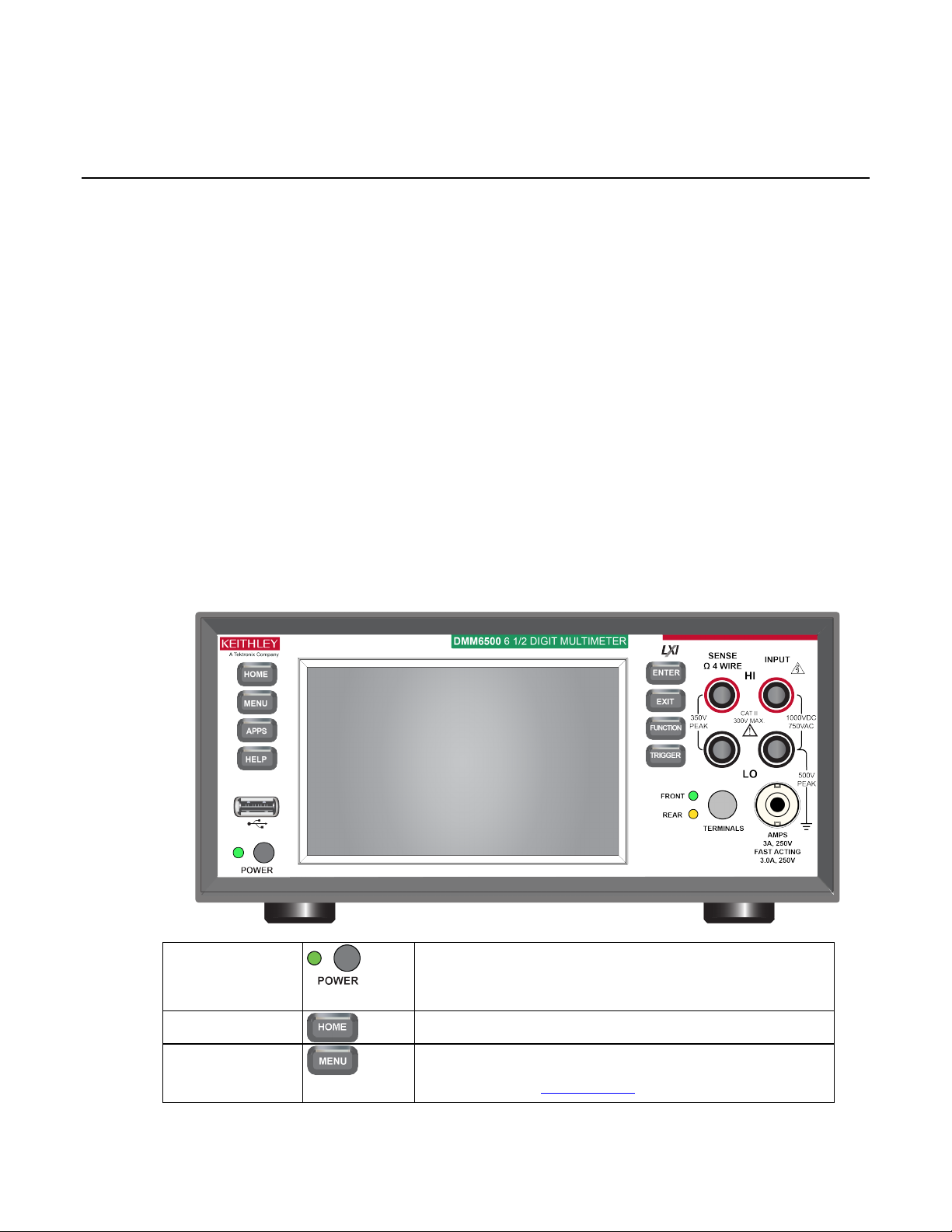
Front-panel overview
The front panel of the DMM6500 is shown below. Descriptions of the controls on the front panel follow
the figure.
Section 2
Front-panel overview
POWER switch
HOME key
Figure 1: DMM6500 front panel
the power switch. To turn it off, pres s and hold the power switch.
The LED is green when the instrument is on and the LED is
MENU key
channel, measure, views, trigger, scripts, and system screens.
For details, refer to Menu overv i ew (on page 2-14).
Page 13
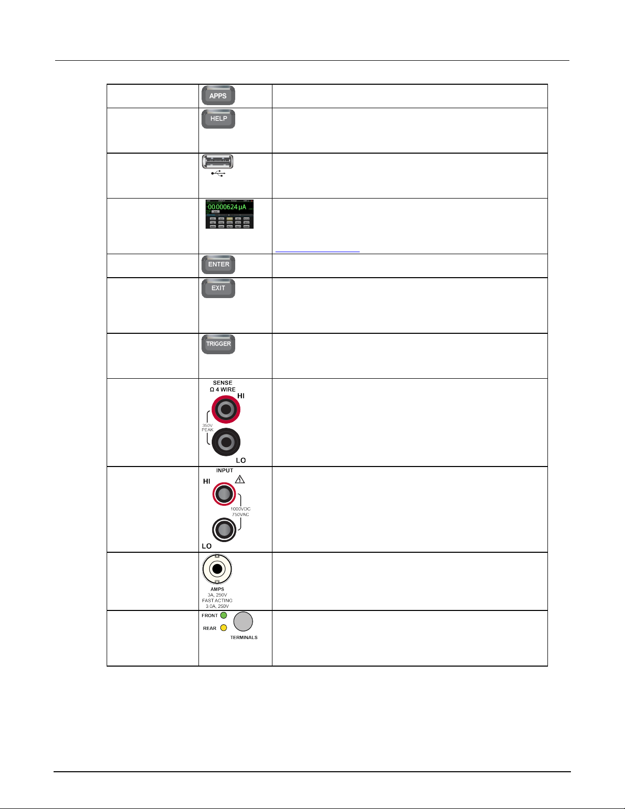
Section
User's Manual
Opens a menu of of preconfigured TSP scripts with a graphical
user interface.
Opens help for the area or item that is selected on the display. If
help, hold the on-screen button while pressing the HELP key.
Saves reading buffer data and scr een snapshots to a USB flash
drive.
The DMM6500 has a high-resolution, five-inch color touchs creen
Touchscreen display (on page 2-4) for det ai ls.
Selects the highlighted choice or allows you to edit the selected
field.
Returns to the previous screen or closes a dialog box. For
to the main menu screen.
DMM6500 Reference Manual.
Use the SENSE HI and SENSE LO terminals and the INPUT
INPUT terminals
Use the INPUT HI and INPUT LO terminals for all measurements
AMPS
Use the AMPS connection with the INPU T LO terminal to
Activates the terminals on the front or rear panel. Selecting the
is visible.
2: Front-panel overview Model DMM6500 6½ Digit Multimeter
APPS key
HELP key
USB port
Touchscreen
ENTER key
EXIT key
TRIGGER key
SENSE terminals
there is no selection when you press the HELP key, it displays
overview information for the screen you are viewing. To display
drive. You can also store and retrieve scripts to and from a USB
flash drive. The flash drive must be formatted as a FAT or FAT32
display. The touchscreen accesses swipe screens and menu
options. You can access additional screens by pressing the
front-panel MENU, APPS, and FUNCTION keys. Refer to
example, press the EXIT key when the main m enu is displayed to
return to the home screen. When you are v iewing a subscreen
(for example, the Event Log screen), press the EXIT key to return
Accesses trigger-related settings and operations. The action of
the TRIGGER key depends on the instrument state. For details,
see "Switching between measurement methods" in the Model
terminals with the 4-wire resistanc e, 3-wire and 4-wire RTD
temperature, and DC voltage ratio functions.
TERMINALS
switch
2-2 DMM6500-900-01 Rev. B / August 2019
except current.
measure ≤3A DC or AC
current.
RMS
rear panel provides the proper connections to an inserted scanner
card. When the front-panel terminals are active, the green LED is
visible. When the rear-panel term inals are active, the amber LED
Page 14
Model DMM6500
panel overview
6½ Digit Multimeter User's Manual Section 2: Front-
Instrument power
Follow the steps below to connect the DMM6500 to line power and turn on the instrument. The
DMM6500 operates from a line voltage of 100 V to 240 V at a frequency of 50 Hz, 60 Hz, or 400 Hz.
It automatically senses line frequency. Make su re t he operating voltage in your area is compatible.
The fuse is set to the expected voltage at the factory. M ake sure that the correct line voltage is
displayed on the power module. See "Line voltage v erification" in the Model DMM6500
Reference Manual for more information.
You must turn on the DMM6500 and allow it to warm up for at l east 30 minutes to achieve rated
accuracies.
Operating the instrument on an incorrect line voltage may cause damage to the instrument,
possibly voiding the warranty.
The power cord supplied with the DMM6500 contains a separate protective earth (safety
ground) wire for use with grounded outlets. When proper connections are made, the
instrument chassis is connected to power-line ground through the ground wire in the power
cord. In the event of a failure, not using a properly grounded protective earth and grounded
outlet may result in personal injury or death due to electric shock.
Do not replace detachable mains supply cords with inadequately rated cords. Failure to use
properly rated cords may result in personal injury or death due to electric shock.
Before installing the instrument, disconnect all external power from the equipment and
disconnect the line cord. Failure to disconnect all power may expose you to hazardous
voltages, which, if contacted, could cause personal injury or death.
Connect the power cord
When you connect the power cord, the instrument m ay power on, depending on the state of the
front-panel POWER switch.
To connect the power cord:
1. Connect the female end of the supplied power cor d to the AC receptacle on the rear panel.
DMM6500-900-01 Rev. B / August 2019 2-3
2. Connect the male end of the power cord to a grounded AC outlet.
Page 15

Section
User's Manual
2: Front-panel overview Model DMM6500 6½ Digit Multimeter
Turn the DMM6500 on or off
On some sensitive or easily damaged device s under test (DUTs), the instrument power-up and
power-down sequence can apply transient signals to the DUT that may affect or damage it. When
testing this type of DUT, do not make final connectio ns t o it until the instrument has completed its
power-up sequence and is in a known operating state . When testing this type of DUT, disconnect it
from the instrument before turning the instrum ent of f.
To prevent any human contact with a live conducto r, connections to the DUT must be fully insulated
and the final connections to the DUT must only use s af ety-rated safety jack socket connectors that
do not allow bodily contact.
To turn a DMM6500 on:
1. Disconnect any devices under test (DUTs) fro m t he DMM6500.
2. Press the front-panel POWER switch to place it in the on position.
The instrument displays a status bar as the instrument powers on. The home screen is displayed
when power on is complete.
To turn a DMM6500 off:
1. Press and hold the front-panel POWER switch to place it in the off position.
Touchscreen display
The touchscreen display gives you quick front-panel access to measure settings, system
configuration, instrument and test status, reading buffer information, and other instrument functionality.
The display has multiple swipe screens that y ou can access by swiping the front panel. You can
access additional interactive screens by pres sing the front-panel MENU, APPS, and FUNCTION
keys.
Do not use sharp metal objects, such as tweezers or screwdrivers, or pointed objects, such
as pens or pencils, to touch the touchscreen. It is strongly recommended that you use only
fingers to operate the instrument. Use of clean-room gloves to operate the touchscreen is
supported.
2-4 DMM6500-900-01 Rev. B / August 2019
Page 16
Model DMM6500
panel overview
6½ Digit Multimeter User's Manual Section 2: Front-
Select items on the touchscreen
To select an item on the displayed screen, pre ss the corresponding icon on the screen.
The following topics describe the DMM6500 touchscreen in more detail.
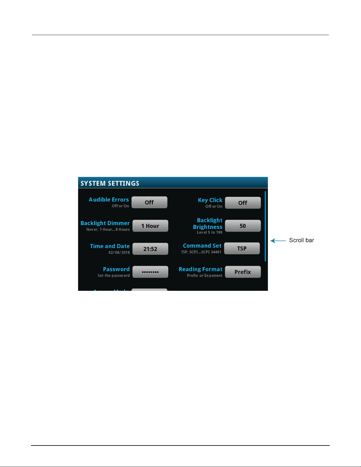
Scroll bars
Some of the interactive screens have additional opti ons that are only visible when you scroll down the
screen. A scroll indicator on the right side of the touchscreen identifies these screens. Swipe the
screen up or down to view the additional options.
The figure below shows a screen with a scroll bar.
Figure 2: Scroll bar
DMM6500-900-01 Rev. B / August 2019 2-5
Page 17
Section
User's Manual
2: Front-panel overview Model DMM6500 6½ Digit Multimeter
Enter information
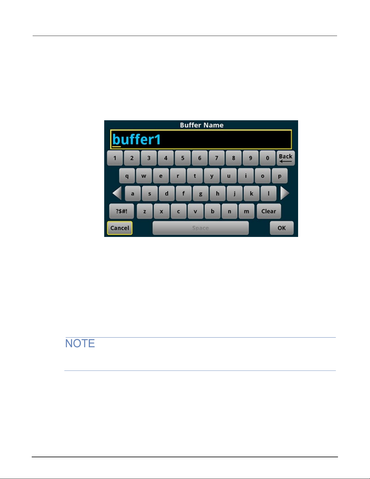
Some of the menu options open a keypad or keybo ard that you can use to enter information. For
example, if you are creating a new reading buff er f rom the front panel, you see the keypad shown in
the following figure.
Figure 3: DMM6500 front-panel keyboard for information entry
You can enter information by touching the screen to select characters and options from the keypad or
keyboard. You can move the cursor in the entry box by touching the screen. The cursor is moved to
the spot in the entry box where you touched the screen.
Adjust the backlight brightness and dimmer
You can adjust the brightness of the DMM6500 t ouchscreen display and buttons from the front panel
or over a remote interface. You can also set the backli ght t o dim after a specified time has passed
with no front-panel activity (available from t he front-panel display only). The backlight settings set
through the front-panel display are saved t hrough a reset or power cycle.
Screen life is affected by how long the screen is on at full brightness. The higher the brightness
setting and the longer the screen is bright, the shorter the screen life.
2-6 DMM6500-900-01 Rev. B / August 2019
Page 18
Model DMM6500
panel overview
6½ Digit Multimeter User's Manual Section 2: Front-
To adjust the backlight brightness from the front panel:
1. Press the MENU key.
2. Under System, select Settings.
3. Select the Backlight Brightness. The Backlight Brightness dialog box opens.
4. Drag the adjustment to set the backlight.
5. Select OK.
To set the backlight dimmer from the front panel:
1. Press the MENU key.
2. Under System, select Settings.
3. Select Backlight Dimmer. The Backlight Dimmer dialog box opens.
4. Select a dimmer setting.
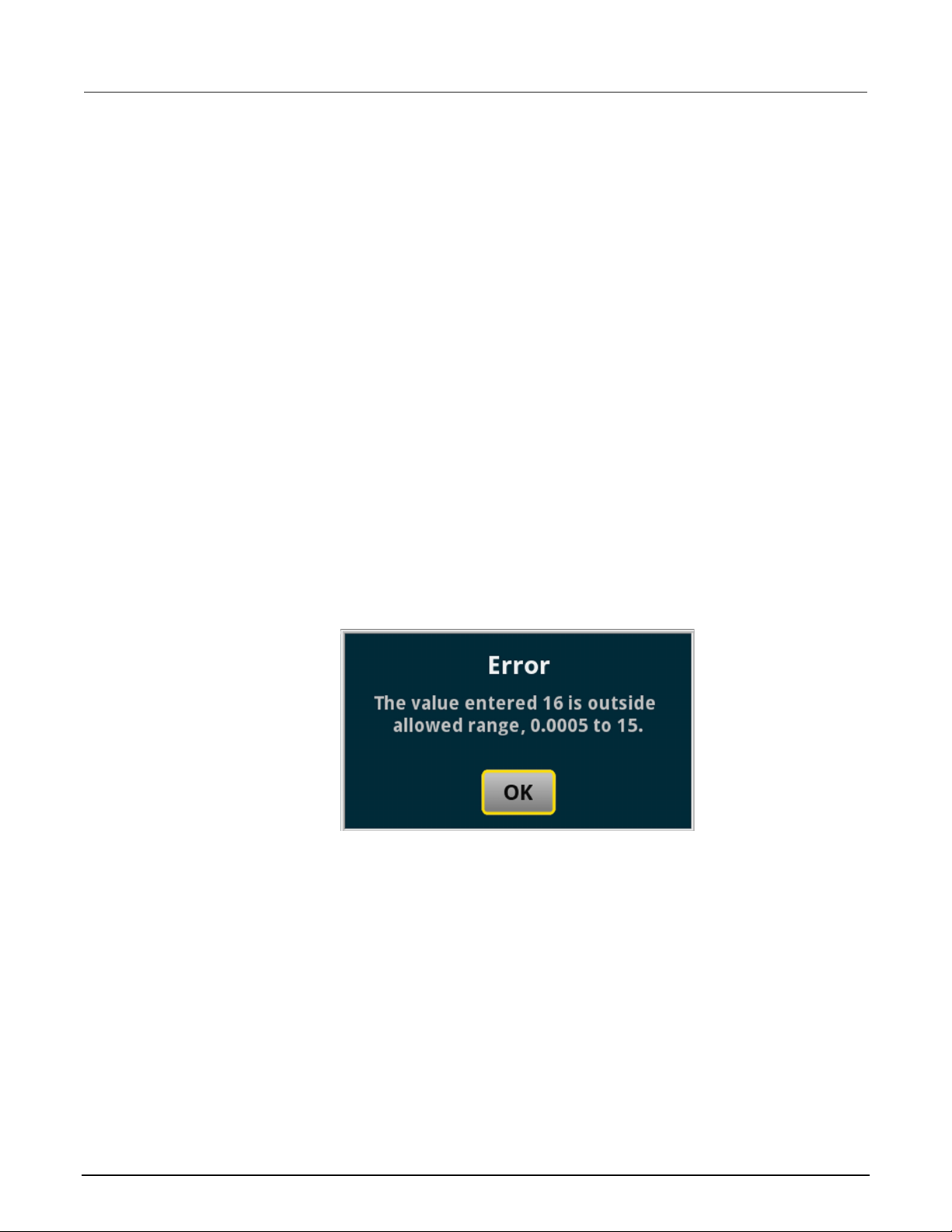
Review event messages
During operation and programming, front-panel m essages may be briefly displayed. Messages are
either information, warning, or error notificati ons. For information on event messages, refer to "Using
the event log" in the Model DMM6500 Reference Manual.
Figure 4: Example front-panel event message
Interactive swipe screens
DMM6500-900-01 Rev. B / August 2019 2-7
The DMM6500 touchscreen display has multi pl e screens that you can access by swiping left or right
on the lower half of the display. The options available in the swipe screens are described in the
following topics.
Swipe screen heading bar
The heading bar of the swipe screen contains the following options.
Page 19
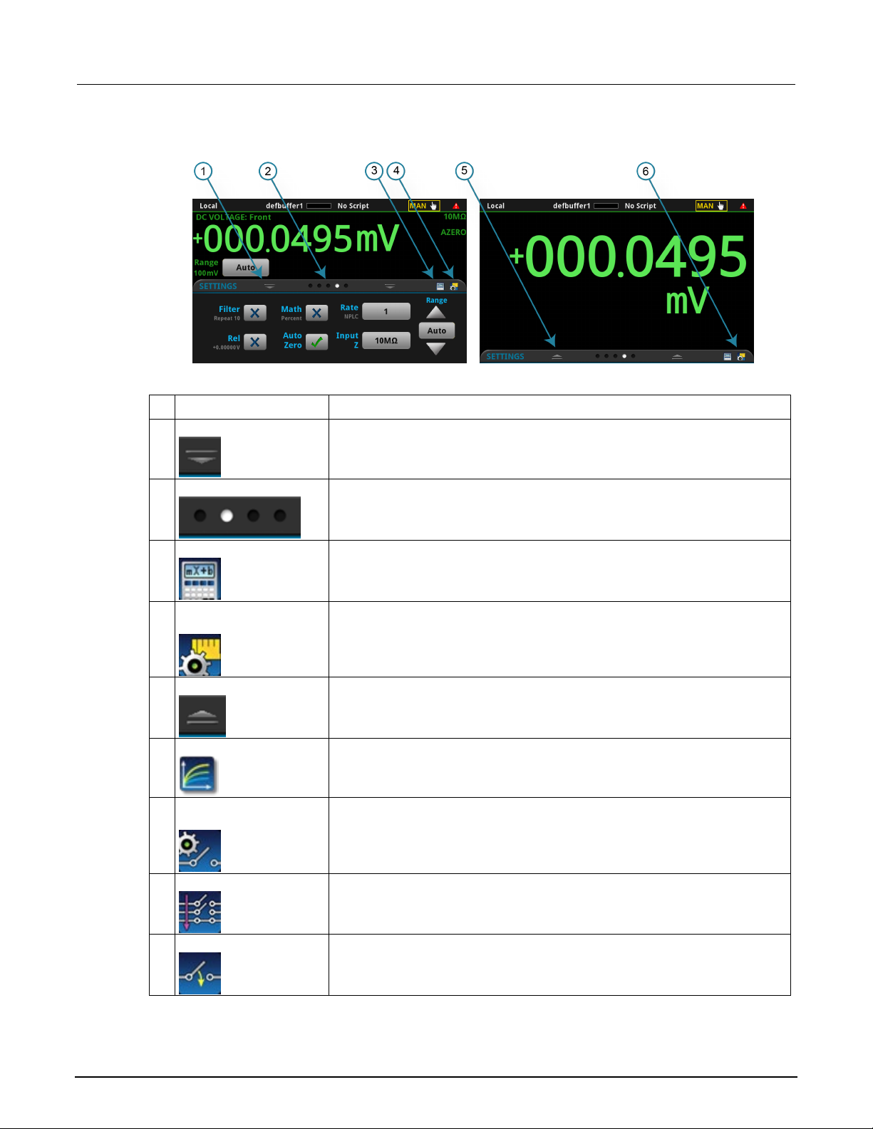
Section
User's Manual
1
Minimize indicator
You can swipe down to minimize the swipe screens.
2
Swipe screen indicator
Each circle represents one swipe screen. As you swipe right or left, a different
3
Calculations shortcut
Select to open the CALCULATION SETTINGS menu. Only available when
4
Measure Settings
Select to open the MEASURE SETT INGS menu for the selected function. Onl y
5
Restore indicator
Indicates that you can swipe up to dis play the swipe screen.
6
Graph shortcut
Select to open the Graph screen.
Scan shortcut
Not shown. Select to open the SCAN scr een. This shortcut is available when
Channel control shortcut
Not shown. Select to open the CHANNEL C ONTROL screen. This shortcut is
2: Front-panel overview Model DMM6500 6½ Digit Multimeter
Figure 5: DMM6500 swipe screens, maximized and minimized
# Screen element Description
shortcut
Channel Settings
shortcut
circle changes color, indicatin g where you are in the screen sequence. Select a
circle to move the swipe screen wit hout swiping.
TERMINALS is set to FRONT.
available when TERMINALS is set to FRONT.
Not shown. Select to open the CHANNEL SETTINGS screen. This shortcut is
on the settings swipe screen when there i s an active closed channel and the
terminals are set to rear.
the terminals are set to rear.
available when the terminals are set to rear.
2-8 DMM6500-900-01 Rev. B / August 2019
Page 20
Model DMM6500
panel overview
6½ Digit Multimeter User's Manual Section 2: Front-
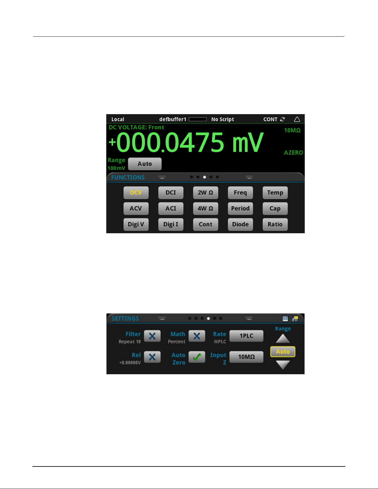
FUNCTIONS swipe screen
The FUNCTIONS swipe screen highlights the selected measure function and allows you to select a
different function.
Figure 6: FUNCTIONS swipe screen
SETTINGS swipe screen
The SETTINGS swipe screen gives you front-panel access to some instrument settings for the
selected measure function. It shows you the present settings and allows you to change them. The
available settings depend on which measure functi on is active.
To disable or enable a setting, select the box next to the setting so that it shows an X (disabled) or a
check mark (enabled).
For descriptions of the settings, select a button, then press the HELP key.
Figure 7: SETTINGS swipe screen
DMM6500-900-01 Rev. B / August 2019 2-9
Page 21
Section
User's Manual
2: Front-panel overview Model DMM6500 6½ Digit Multimeter
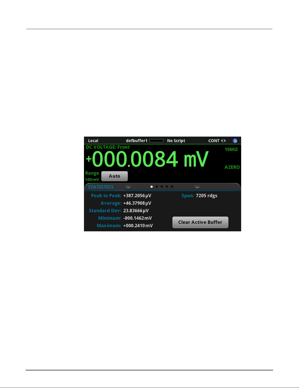
STATISTICS swipe screen
The STATISTICS swipe screen contains informati on about the readings in the active reading buffer.
When the reading buffer is configured to fill cont i nuously and overwrite old data with new data, the
buffer statistics include the data that was overwrit ten. To get statistics that do not include data that
has been overwritten, define a large buffer size that will accommodate the number of readings you
will make. You can use the Clear Active Buffer butto n on this screen to clear the data from the active
reading buffer.
If multiple watch channels are set up, you can use the Channel arrows to change the display to show
the statistics for each watch channel.
Figure 8: STATISTICS swipe screen
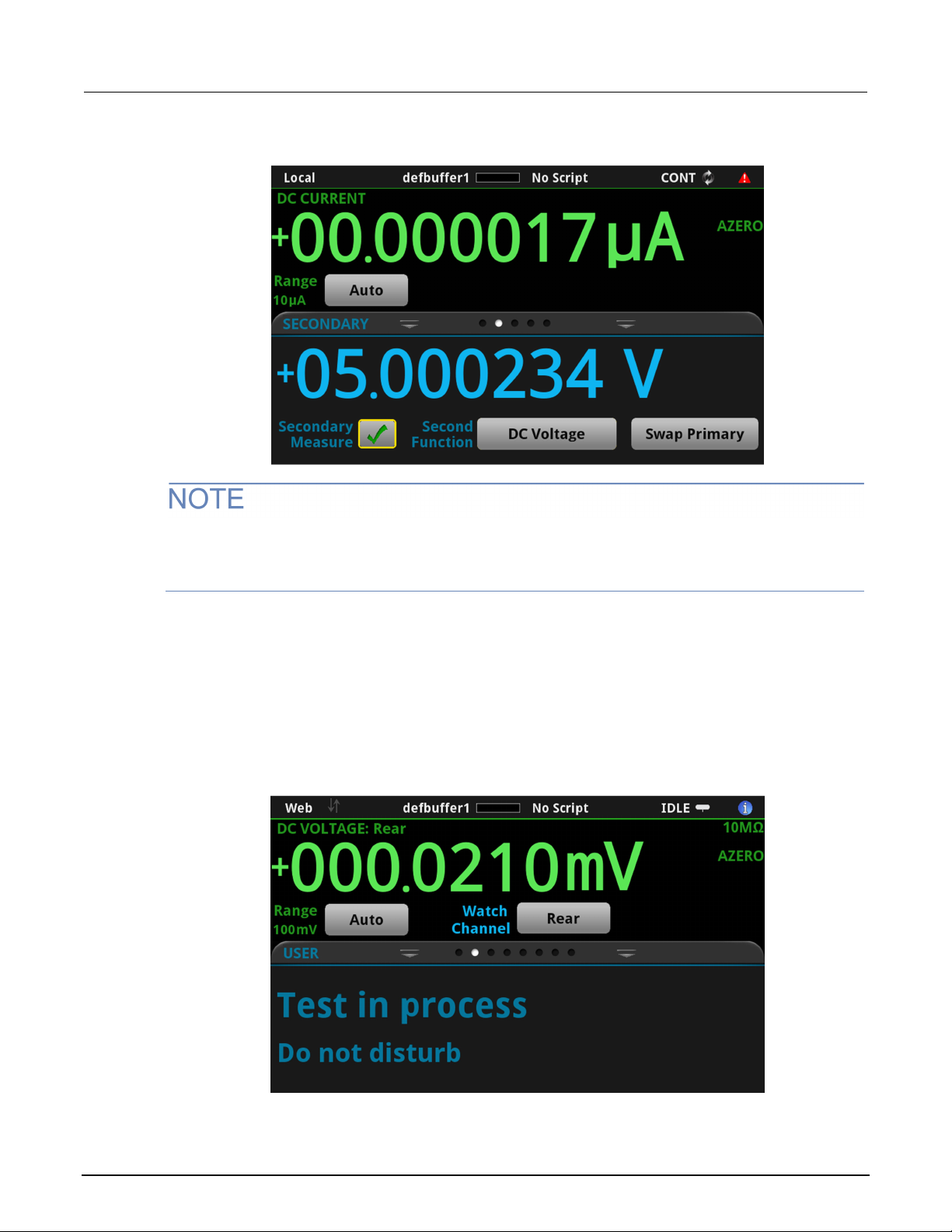
SECONDARY swipe screen
The SECONDARY swipe screen allows you to display the results of two measurements on the
front-panel display.
To start displaying secondary measurements, select the Second Function and select Secondary
Measure. Secondary measurements are only available in Continuous Measurement Mode and
Manual Trigger Mode. This feature is only available from the front panel of the instrument.
Refer to "Display results of two measure function s" in the Model DMM6500 Reference Manual.
2-10 DMM6500-900-01 Rev. B / August 2019
Page 22
Model DMM6500
panel overview
6½ Digit Multimeter User's Manual Section 2: Front-
Figure 9: SECONDARY swipe screen
Depending on the selected functions, a relay may click when the instrument switches between the
measurement types. Leaving secondary meas urements on for extended periods may shorten the life
of the relays.
USER swipe screen
If you program custom text, it is displayed on the USE R swipe screen. For example, you can program
the DMM6500 to show that a test is in process. This swi pe screen is only displayed if custom text has
been defined. Refer to “Customizing a message f or t he US E R swipe screen” in the Model DMM6500
Reference Manual.
Figure 10: USER swipe screen
DMM6500-900-01 Rev. B / August 2019 2-11
Page 23
Section
User's Manual
2: Front-panel overview Model DMM6500 6½ Digit Multimeter
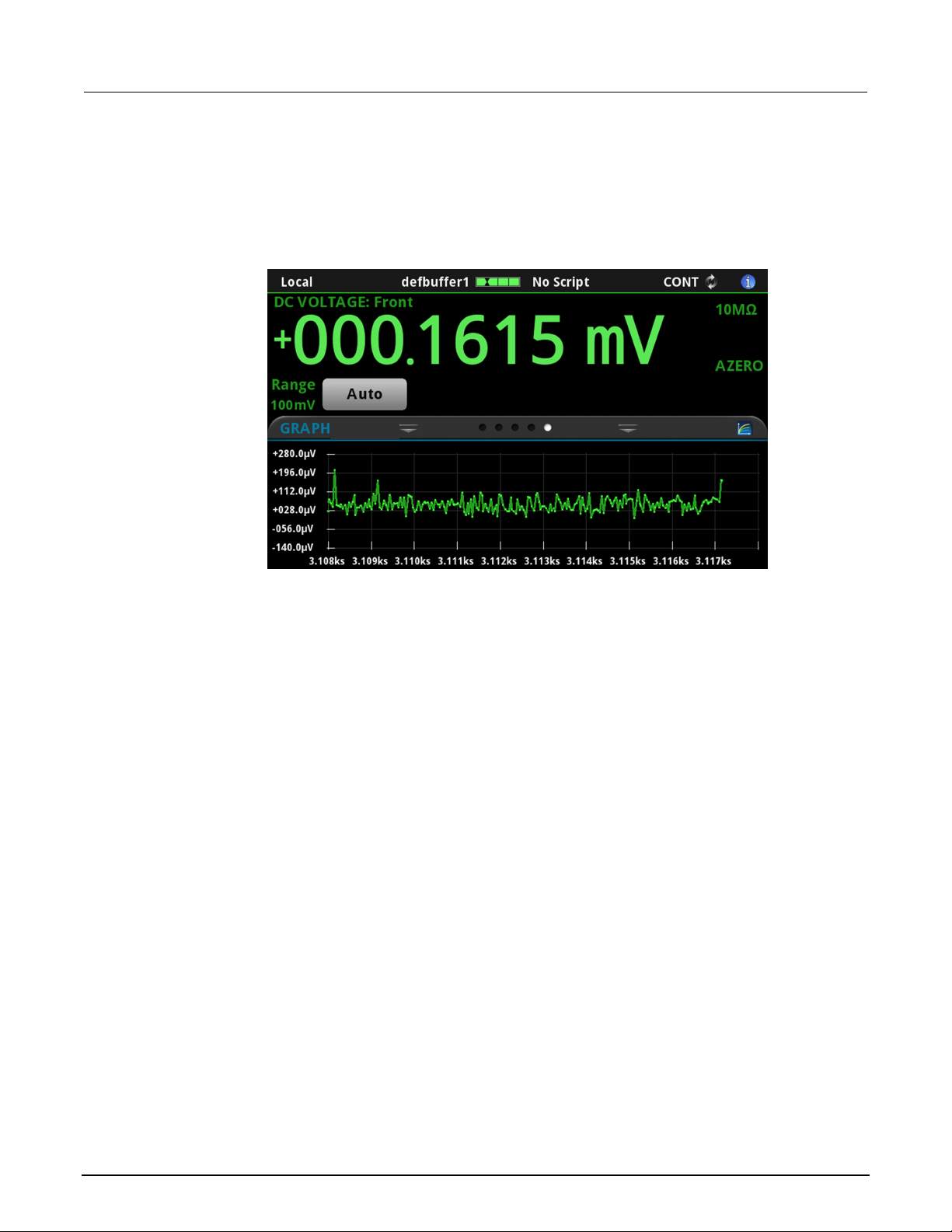
GRAPH swipe screen
The GRAPH swipe screen shows a graphical rep resentation of the readings in the presently selected
reading buffer.
Figure 11: GRAPH swipe screen
To view the graph in the full screen and to access gra ph set t i ngs, select the graph icon on the right
side of the swipe screen header. You can also open the full-function Graph screen by pressing the
MENU key and selecting Graph under Views.
For more information about graphing measurements, see “Graphing” in the Model DMM6500
Reference Manual.
SCAN swipe screen
The SCAN swipe screen gives you front-panel access to build a scan, edit a scan, start a scan, step
through a scan, and display scan results. You can al so save the scan results to a USB flash drive.
The icon on the right side of the swipe screen headi ng bar is a shortcut to the Channel Scan menu.
You can also use the Channel Scan menu to build or edi t a sca n.
When a scan is running, the remaining time and sc an count are displayed.
For more information about viewing a scan preview and editing or running a scan, see "Channel scan
menu" in the Model DMM6500 Reference Manu al .
2-12 DMM6500-900-01 Rev. B / August 2019
Page 24
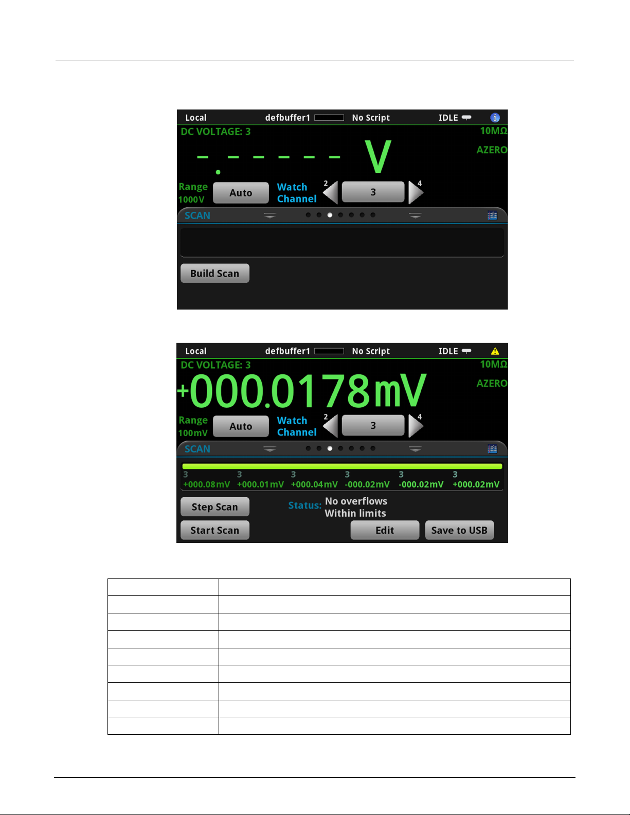
Model DMM6500
panel overview
Stop the scan.
Opens the SCAN screen, where you can se t up a new scan.
Opens the SCAN screen, where you can change the setup of a scan.
Pauses the scan until Resume Scan is sel ected.
Resumes a paused scan.
Runs a scan.
Incrementally steps through a s c an, channel by channel.
6½ Digit Multimeter User's Manual Section 2: Front-
Figure 12: SCAN swipe screen - initial view
Figure 13: SCAN swipe screen - scan results
The SCAN swipe screen has the following control options:
Button Description
Abort Scan
Build Scan
Edit
Pause Scan
Resume Scan
Save to USB
Start Scan
Step Scan
DMM6500-900-01 Rev. B / August 2019 2-13
Saves the data in the scan reading buf fer to a CSV file on the USB flash drive.
Page 25
Section
User's Manual
2: Front-panel overview Model DMM6500 6½ Digit Multimeter
Menu overview
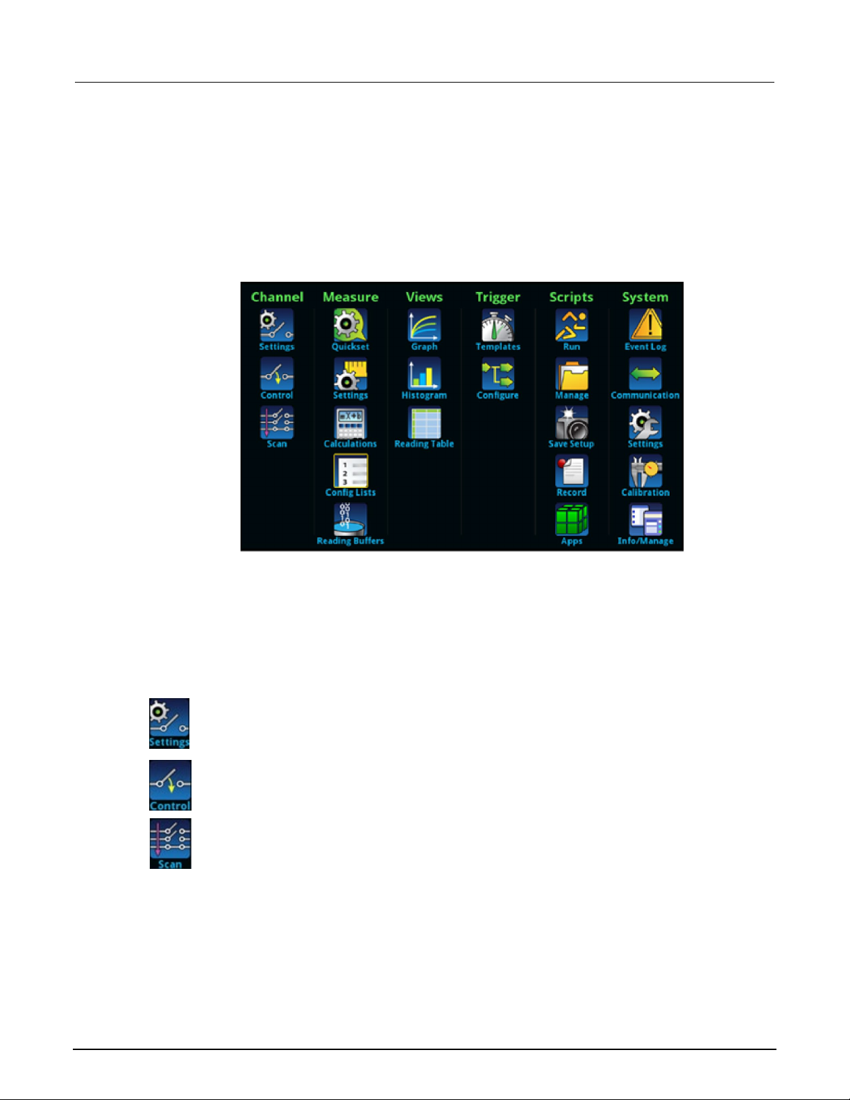
To access the main menu, press the MENU key on the DMM6500 front panel. The figure below
shows the organization of the main menu.
Figure 14: DMM6500 main menu
The main menu includes submenus that are labeled in green across the top of the display. Selecting
an option in a submenu opens an interactive screen.
Channel menu
The Channel menus allow you to set up and control channels and scans from the front panel.
The Channel Settings menu contains options to set up the measurement functions for each
channel.
The Channel Control menu contains options to open and close channels.
The Channel Scan menu contains options to set up and run scans. Options include control
of groups, which are channels that are sequential and have the same functions applied to
them.
2-14 DMM6500-900-01 Rev. B / August 2019
Page 26
Model DMM6500
panel overview
6½ Digit Multimeter User's Manual Section 2: Front-
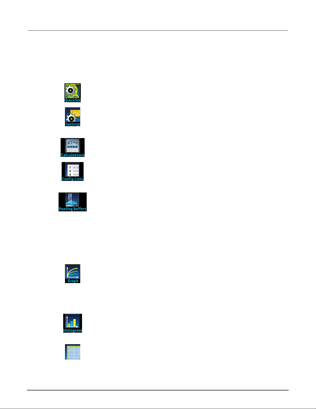
Measure menu
The Measure menus allow you to select, configure, and perform measure operations from the front
panel.
The QuickSet menu allows you to change the f unct i on and adjust performance.
The Measure Settings menu contains settings for the presently selected measure
function, which is identified by the function indic ator in the upper right corner of the
menu. The available settings depend on the front-panel FUNCTION key selection.
The Calculations menu contains settings that specify the way measurem ent
information is processed and returned.
The Config Lists menu allows you t o select an existing measure configuration list,
create a new list, load configuration settings to and from the instrument, and view
the settings of an index in a configuration list.
Views menu
The Views menus allow you to select, configure, and view data that was gathered from measure
operations.
The Reading Buffers menu allows you to view the list of existing reading buffers
and select one to be the active buffer. You can also creat e, save, delete, resize,
and clear buffers from this screen.
The Graph menu opens a screen that displays a graph of the measurements in
selected reading buffers as traces. It also contains tabs that you use to customize
the graph display.
You can also select the trigger mode and initiate the trigger model or scan from this
screen.
The Histogram menu allows you to graph the distribution of measurement data in
the selected reading buffer. It also contains tabs that you use to customize the
histogram.
DMM6500-900-01 Rev. B / August 2019 2-15
This menu allows you to view data in the selected reading buffer.
Page 27
Section
User's Manual
2: Front-panel overview Model DMM6500 6½ Digit Multimeter
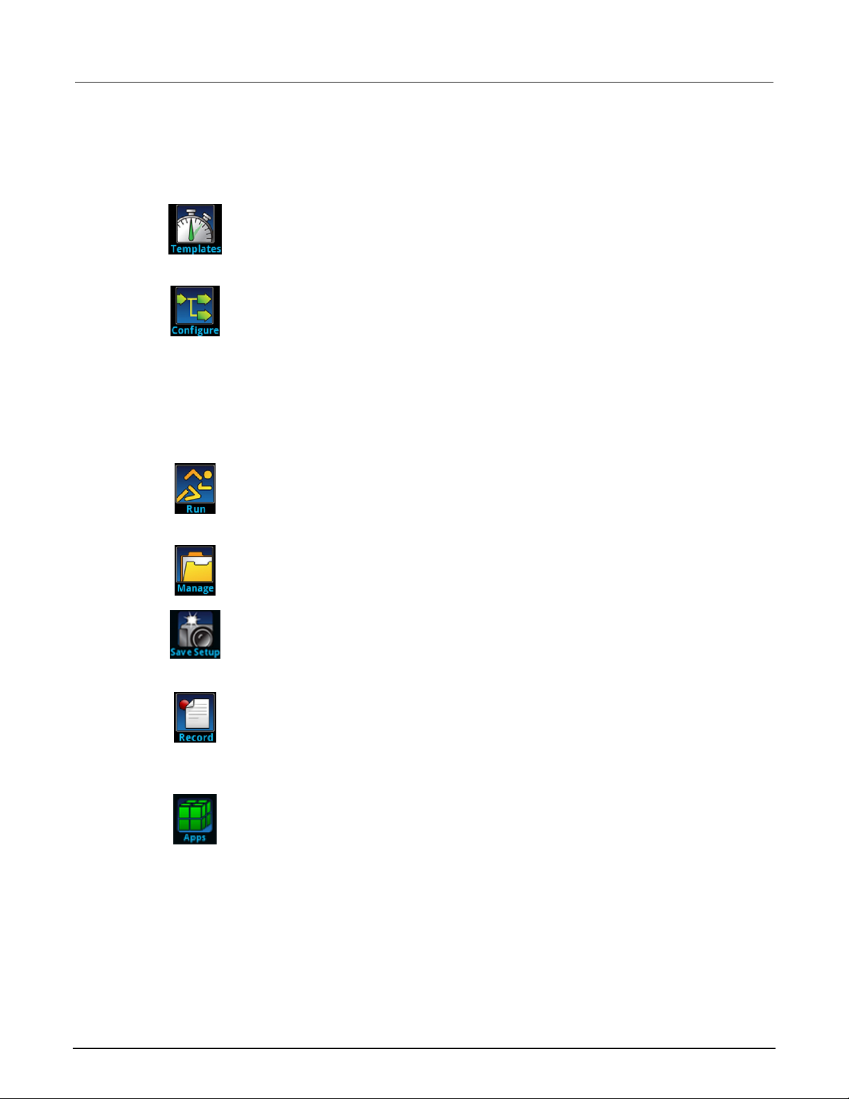
Trigger menu
The Trigger menus allow you to configure the trig ger model from the front panel.
Scripts menu
The Scripts menus allow you to configure, run, and manage scripts from the front panel. Scripts are
blocks of commands that the instrument can run as a group.
The Templates menu allows you to choose from one of several preprogrammed
trigger models. When you select a template, set t i ngs you can specify for that
template are shown in the lower part of the screen.
The Configure menu allows you to view and modify the structure and parameters
of a trigger model. You can also monitor trigger model operation.
The Run menu contains a list of scripts that you can select to run immediately. You
can also copy a script to a script that runs each time the instrument power is turned
on. You can access scripts that are in the instrument or on a USB flash drive.
The Manage menu allows you to copy scripts t o and from the instrument and the
USB flash drive. You can also delete scripts from t he instrument or USB flash drive.
The Save Setup menu allows you to save the present settings and conf i guration
lists of the instrument into a configuration script . You can use this script to recall the
settings.
The options in the Record menu allow you to record your actions and store them in
a macro script. The script can be run and managed like any other script using the
options in the Scripts menu or remote commands. Note that only settings are
stored; no key presses or front-panel only options are stored.
Open the APPS MANAGER, which allows you to manage prebuilt TSP®
applications. TSP applications are Keithley-dev eloped programs that enable the
DMM6500 to use specialized functions, test aut om ation, and visualize information
on the user interface. TSP applications are availa ble when the instrument is used in
the TSP or SCPI command set. Many of the applications are pre-installed on your
DMM6500.
2-16 DMM6500-900-01 Rev. B / August 2019
Page 28
Model DMM6500
panel overview
6½ Digit Multimeter User's Manual Section 2: Front-
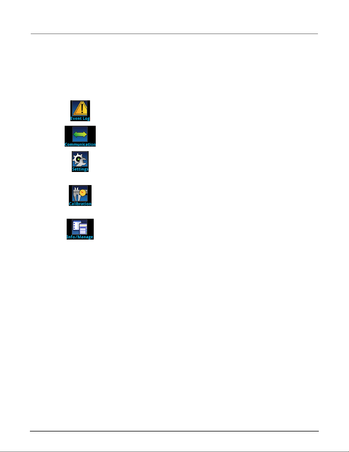
System menu
The menus under System in the main menu allow you to configure general instrument settings from
the DMM6500 front panel. Among these settings a re the event log, communications, backlight, tim e,
and password settings, calibration, and system i nformation.
The Event Log menu allows you to view and clear event log entries. You can also
adjust which events are displayed or logged.
The Communication menu opens a set of tabs that contain inf ormation about the
communications settings. Most of the tabs contain settings that you can change.
The Settings menu contains general instrument settings. I t includes beeper and
key click, backlight brightness and timer, time and date, system access level,
password, and reading format settings.
The Calibration menu displays factory calibrat i on i nformation, including the last
adjustment date, the last calibration date, and the number of times the instrument
has been adjusted.
The Info/Manage menu gives you access to version and serial number information
and settings for instrument firmware and re set f unct i ons.
DMM6500-900-01 Rev. B / August 2019 2-17
Page 29

Determining the command set you will use ............................ 3-20
Using a remote interface
In this section:
Remote communications interfaces ......................................... 3-1
Supported remote interfaces .................................................... 3-1
LAN communications ............................................................... 3-2
USB communications ............................................................... 3-5
GPIB communications ............................................................ 3-10
RS-232 ................................................................................... 3-13
TSP-Link ................................................................................ 3-16
Using the web interface .......................................................... 3-18
Remote communications interfaces
Section 3
You can choose from one of several communication i nterfaces to send commands to and receive
responses from the DMM6500.
The instrument automatically detects the type of communications interface (LAN, USB, GPIB, RS-232,
®
or TSP-Link
RS-232, and TSP-Link options require an optional accessory card. In most cases, you do not need to
configure anything on the instrument. In addit ion, you do not need to reboot if you change the type of
interface that is connected.
You can only use one communications interface to control the DMM6500 at a time. The USB
connection takes precedence over LAN con nections. For other communications interfaces, the f i rst
interface on which the instrument receives a me ssage takes control of the instrument. If another
interface sends a message, that interface can tak e control of the instrument. You may need to enter a
password to change the interface, depending on the selected interface access.
) when you connect to the respective port on the rear panel of the instrument. The GPIB,
Supported remote interfaces
The DMM6500 supports the following remote interfaces:
• GPIB: IEEE-488 instrumentation general purpose interface bus
• Ethernet: Local-area-network communications
• RS-232: Serial communication data standard
• USB: Type B USB port
• TSP-Link: A high-speed trigger synchronization and communications bus that test system
builders can use to connect multiple instruments in a master-and-subordinate configuration
Page 30

Section
User's Manual
3: Using a remote interface Model DMM6500 6½ Digit Multimeter
The GPIB, RS-232, and TSP-Link interfaces require an optional com m unications accessory card to
be installed in the instrument. Accessory car ds include the KTTI-GPIB, KTTI-TSP, and KTTI-RS232.
For details about TSP-Link, see “TSP-Link System E xpansion Interface” in the Model DMM6500
Reference Manual.
The rear-panel connections for the remote communication interfaces are shown in the following
figure.
Figure 15: DMM6500 remote interface connections
LAN communications
You can communicate with the instrument using a lo cal area network (LAN).
When you connect using a LAN, you can use a web browser to access the internal web page of the
instrument and change some of the instrument set t i ngs. For more information, see
interface (on page 3-18).
The DMM6500 is a version 1.5 LXI Device Specification 2016 instrument that supports TCP/IP and
complies with IEEE Std 802.3 (ethernet LAN). There is one LAN port on the rear panel of t he
instrument that supports full connectivity on a 10 Mbps or 100 Mbps network. The DMM6500
automatically detects the speed.
The DMM6500 also supports Multicast DNS (mDNS) and DNS Service Discovery (DNS-SD), which
are useful on a LAN with no central administration.
Contact your network administrator to confirm your specific network requirements before settin g up a
LAN connection.
Using the web
If you have problems setting up the LAN, refer to LAN t roubles hooti ng sugge stio ns (on page 3-18
3-2 DMM6500-900-01 Rev. B / August 2019
).
Page 31

Model DMM6500
Using a remote interface
6½ Digit Multimeter User's Manual Section 3:
Set up LAN communications on the instrument
This section describes how to set up manual or automatic LAN communications on the instrument.
Check communication settings
Before setting up the LAN configuration, you can check the communication settings on the instrument
without making any changes.
To check communication settings on the instrument:
1. Press the MENU key.
2. Under System, select Communication. The SYSTEM COMMUNICATIONS window opens.
3. Select LAN to see the settings for that interface.
4. Press the EXIT key to leave the SYSTEM COMMUNICATION window without making any
changes.
Set up automatic LAN configuration
If you are connecting to a LAN that has a DHCP server or if you have a direct connection between the
instrument and a host computer, you can use automatic IP address selection.
If you select Auto, the instrument attempts to get an IP address from a DHCP server. If this fails, it
reverts to an IP address in the range of 169.254.1.0 through 169.254.254.255.
Both the host computer and the instrument should be set to use automatic LAN configuration.
Though it is possible to have one set to manual configuration, it is more complicated to set up.
To set up automatic IP address selection using the front panel :
1. Press the MENU key.
2. Under System, select Communication.
3. Select the LAN tab.
4. For TCP/IP Mode, select Auto.
5. Select Apply Settings to save your settings.
DMM6500-900-01 Rev. B / August 2019 3-3
Page 32

Section
User's Manual
3: Using a remote interface Model DMM6500 6½ Digit Multimeter
Set up manual LAN configuration
If necessary, you can set the IP address on the instrument manually.
You can also enable or disable the DNS settings and assign a host name to the DNS server.
Contact your corporate information technology (I T ) department to secure a valid IP address for the
instrument when placing the instrument on a corpo rate network.
The instrument IP address has leading zeros, but the computer IP address cannot.
To set up manual IP address selection on the instrument:
1. Press the MENU key.
2. Under System, select Communication.
3. Select the LAN tab.
4. For TCP/IP Mode, select Manual.
5. Enter the IP Address.
6. Enter the Gateway address.
7. Enter the Subnet mask.
8. Select Apply Settings to save your settings.
Set up LAN communications on the computer
This section describes how to set up the LAN communications on your computer.
Do not change your IP address without consulting your system administrator. If you enter an
incorrect IP address, it can prevent your computer f rom connecting to your corporate network or it
may cause interference with another network ed computer.
Record all network configurations before modif ying any existing network configuration information on
the network interface card. Once the network configuration settings are updated, the previous
information is lost. This may cause a problem reconnecting the host computer to a corporate network,
particularly if DHCP is disabled.
Be sure to return all settings to their original co nfiguration before reconnecting the host computer to a
corporate network. Contact your system admini st rator for more information.
3-4 DMM6500-900-01 Rev. B / August 2019
Page 33

Model DMM6500
Using a remote interface
6½ Digit Multimeter User's Manual Section 3:
Verify the LAN connection on the DMM6500
Make sure that your DMM6500 is connected to the n etwork by confirming that your instrument was
assigned an IP address.
To verify the LAN connection:
1. Press the MENU key.
2. Under System, select Communication.
3. Select the LAN tab.
A green LAN status indicator on the lower left of the LAN tab confirms that your instrument was
assigned an IP address.
Use the LXI Discovery Tool
To find the IP address of the DMM6500, use the LXI D isc overy Tool, a utility that is available from the
Resources tab of the LXI Consortium website (lxistandard.org/
).
USB communications
To use the rear-panel USB port, you must have the Vi rt ual Instrument Software Architecture (VISA)
layer on the host computer. See “How to install the Kei thley I/O Layer” in the Model DMM6500
Reference Manual for more information.
VISA contains a USB-class driver for the USB Test and Mea surement Class (USBTMC) protocol that,
once installed, allows the Microsoft
When you connect a USB device that implements the USBTMC or USBTMC-USB488 protocol to the
computer, the VISA driver automatically detects the device. Note that the VISA driver only
automatically recognizes USBTMC and USBTMC-USB488 devices. It does not recognize other USB
devices, such as printers, scanners, and storage devices.
In this section, “USB instruments” refers to devi ces that implement the USBTMC or
USBTMC-USB488 protocol.
®
Windows® operating system to recognize the instrument .
DMM6500-900-01 Rev. B / August 2019 3-5
Page 34

Section
User's Manual
3: Using a remote interface Model DMM6500 6½ Digit Multimeter
Connect a computer to the DMM6500 using USB
To communicate from a computer to the instrument, you need a USB cable with a USB Type B
connector end and a USB type A connector end. You need a separate USB cable for each instrument
you plan to connect to the computer at the same time using the USB interface.
To connect an instrument to a computer using USB:
1. Connect the Type A end of the cable to the computer.
2. Connect the Type B end of the cable to the instrument.
3. Turn on the instrument power. When the computer detect s t he new USB connection, the Found
New Hardware Wizard starts.
4. If the “Can Windows connect to Windows Update to s earch for software?” dialog box opens,
select No, and then select Next.
5. On the “USB Test and Measurement device” dialog box, select Next, and then select Finish.
Communicate with the instrument
For the instrument to communicate with the USB device, you must use NI-VISATM. VISA requires a
resource string in the following format to conne ct to the correct USB instrument:
USB0::0x05e6::0x6500::[serial number]::INSTR
Where:
• 0x05e6: The Keithley vendor ID
• 0x6500: The instrument model number
• [serial number]: The serial number of the instrument (the serial number is also on the rear
panel)
• INSTR: Use the USBTMC protocol
The resource string is displayed on the bottom right of the System Communications screen when the
USB connection is active. Select Menu, then Communication to open the System Communications
menu and select the USB tab.
You can also retrieve the resource string by runni ng t he K ei thley Configuration Panel, which
automatically detects all instruments connected to the computer.
If you installed the Keithley I/O Layer, you can access the Keithley Configuration Panel through the
®
Microsoft
If you have a USB connection, you cannot switch to a LA N c onnection while the USB is connected.
USB takes precedence over LAN.
3-6 DMM6500-900-01 Rev. B / August 2019
Windows® Start menu.
Page 35

Model DMM6500
Using a remote interface
6½ Digit Multimeter User's Manual Section 3:
To use the Keithley Configuration Panel to determine the VISA resource string:
1. Click Start > Keithley Instruments > Keithley Configuration Panel. The Select Operation
dialog box is displayed.
Figure 16: Select Operation dialog box
2. Select Add.
3. Select Next. The Select Communication Bus dialog box is displayed.
Figure 17: Select Communication Bus dialog box
DMM6500-900-01 Rev. B / August 2019 3-7
Page 36

Section
User's Manual
3: Using a remote interface Model DMM6500 6½ Digit Multimeter
4. Select USB.
Figure 18: Select Instrument Driver dialog box
5. Click Next. The Select Instrument Driver dialog box is displayed.
6. Select Auto-detect Instrument Driver - Model.
7. Click Next. The Configure USB Instrument dialog box is displayed wit h t he detected instrument
VISA resource string visible.
8. Click Next. The Name Virtual Instrument dialog box is displayed.
Figure 19: Name Virtual Instrument dialog box
3-8 DMM6500-900-01 Rev. B / August 2019
Page 37

Model DMM6500
Using a remote interface
6½ Digit Multimeter User's Manual Section 3:
9. In the Virtual Instrument Name box, enter a name that you want to use to refer to the instrument.
10. Select Finish.
11. Select Cancel to close the Wizard.
Verify the instrument through the Keithley Communicator:
12. Save the configuration. From the Keithley Configuration Panel, select File > Save.
1. Set the instrument to use the SCPI command set. Refer to How do I change the command set?
(on page 3-20) for instruction.
2. Click Start > Keithley Instruments > Keithley Communicator.
3. Select File > Open Instrument to open the instrument you just named.
Figure 20: Keithley Communicator Open an Instrument
4. Click OK.
5. Send a command to the instrument and see if it responds.
If you have a full version of NI-VISA on your system, you ca n run NI-MAX or the VISA Interactive
Control utility. See the National Instruments documentation for information.
DMM6500-900-01 Rev. B / August 2019 3-9
Page 38

Section
User's Manual
3: Using a remote interface Model DMM6500 6½ Digit Multimeter
GPIB communications
The DMM6500 GPIB interface is IEEE Std 488.1 compliant and supports IEEE Std 488.2 common
commands and status model topology.
You can have up to 15 devices connected to a GPIB interfa ce, i ncluding the controller. The maximum
cable length is the lesser of either:
• The number of devices multiplied by 2 m (6.5 ft)
• 20 m (65.6 ft)
You may see erratic bus operation if you ignore these limits.
GPIB communications require the KTTI-GPIB communications accessory card to be installed in the
instrument.
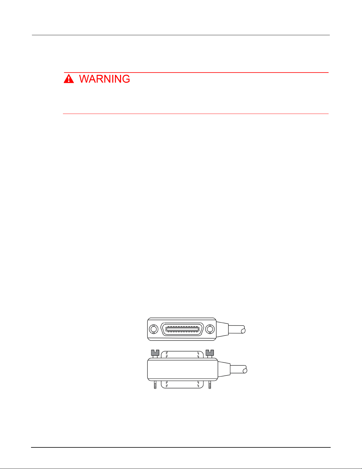
Install the KTTI-GPIB accessory card
Figure 21: KTTI-GPIB connector view
Unpack and inspect
Make sure to handle the KTTI-GPIB card carefully. Always grasp the card by the side edges.
Do not touch board surfaces, components, or areas adjacent to electrical contacts.
Contamination from foreign materials such as dirt, dust, and body oils can substantially
degrade card performance.
To unpack and inspect your card:
1. Inspect the box for damage.
2. Open the box.
3. Remove the card and inspect for any obvious sign s of physical damage.
4. Report any damage to the shipping agent immediat ely.
3-10 DMM6500-900-01 Rev. B / August 2019
Page 39
Model DMM6500
Using a remote interface
Installation
6½ Digit Multimeter User's Manual Section 3:
Slot covers must be installed on unused slots to prevent personal contact with high-voltage
circuits. Failure to recognize and observe standard safety precautions could result in
personal injury or death due to electric shock.
To install the communications card:
1. Turn the instrument off and disconnect the power l ine cord and any other cables connected to the
rear panel.
2. Position the instrument so that you are facing the rear panel.
3. Remove the slot cover plate from the slot on the back of t he inst rument. Retain the plate and
screws for future use.
4. Align the card with the connector toward the inside edge of the slot and slide the card into the
chassis. For the last ¼ inch, press in firmly to mat e the ca rd to the connector.
5. On each side of the card, there is a spring-loaded mo unting screw. Tighten these two screws,
either by hand or with a Phillips-head screwdriver, t o secure the card in the case. Do not
overtighten.
6. Reconnect the power line cable and any other cables to the rear panel.
7. Turn on the instrument.
Connect GPIB cables to your instrument
To connect a DMM6500 to the GPIB interface, use a cable equipped with standard GPIB connectors,
as shown below.
Figure 22: GPIB connector
DMM6500-900-01 Rev. B / August 2019 3-11
Page 40

Section
User's Manual
3: Using a remote interface Model DMM6500 6½ Digit Multimeter
To allow many parallel connections to one instrument, stack the connectors. Each connector has two
screws on it to ensure that connections remain secure. The figure below shows a typical connection
diagram for a test system with multiple instruments.
To avoid possible mechanical damage, stac k no more than three connectors on any one
instrument. To minimize interference caused by electromagnetic radiation, use only shielded
GPIB cables. Contact Keithley Instrumen ts for shielded cables.
Figure 23: DMM6500 instrument GPIB connections
Additional information
Additional information is available in the KTTI-GPIB Communication and Digital I/O Accessory
Instruction Sheet, part number 0771437XX, where XX is the document revision number.
3-12 DMM6500-900-01 Rev. B / August 2019
Page 41

Model DMM6500
g a remote interface
6½ Digit Multimeter User's Manual Section 3: Usin
Set the GPIB address
The default GPIB address is 16. You can set the address from 1 to 30 if it is unique in the system.
This address cannot conflict with an addres s t hat is assigned to another instrument or to the GPIB
controller.
GPIB controllers are usually set to 0 or 21. To be safe, do not configure any instrument to have an
address of 21.
The instrument saves the address in nonvolatile memory. It does not change when you send a reset
command or when you turn the power off and on agai n.
To set the GPIB address from the front panel:
1. Press the MENU key.
2. Select Communication.
3. Select the GPIB tab.
4. Set the GPIB Address.
5. Select OK.
You can also set the GPIB address using remote com m ands. Set the GPIB address with the SCPI
command :SYSTem:GPIB:ADDRess or the TSP command gpib.address.
RS-232
You can communicate with the instrument using RS-232 if a KTTI-RS232 communications accessory
card is installed in the instrument.
The card provides six independently configur able digital input/output lines that can be used to control
external digital circuitry, for example, a handler t hat is used to perform binning operations. The digital
I/O port is a standard female DB-9 connector. You c an also use these lines for triggering. The
instrument can generate output trigger pulses and detect input trigger pulses.
DMM6500-900-01 Rev. B / August 2019 3-13
Page 42

Section
User's Manual
3: Using a remote interface Model DMM6500 6½ Digit Multimeter
Install the KTTI-RS232 accessory card
Figure 24: KTTI-RS232 panel view
Unpack and inspect
Make sure to handle the KTTI-RS232 card carefully. Always grasp the card by the side edges.
Do not touch board surfaces, components, or areas adjacent to electrical contacts.
Contamination from foreign materials such as dirt, dust, an d body oils can substantially
degrade card performance.
To unpack and inspect your card:
1. Inspect the box for damage.
2. Open the box.
3. Remove the card and inspect for any obvious sign s of physical damage.
4. Report any damage to the shipping agent immediately.
Installation
Slot covers must be installed on unused slots to prevent personal contact with high-voltage
circuits. Failure to recognize and observe standard safety precautions could result in
personal injury or death due to electric shock.
To install the communications card:
1. Turn the instrument off and disconnect the power li ne cord and any other cables connected to the
rear panel.
2. Position the instrument so that you are facing the rear panel.
3. Remove the slot cover plate from the slot on the back of the instrument. Retain the plate and
screws for future use.
4. Align the card with the connector toward the inside edge of the slot and slide the card into the
chassis. For the last ¼ inch, press in firmly to mat e the ca rd to the connector.
5. On each side of the card, there is a spring-loaded mo unting screw. Tighten these two screws,
either by hand or with a Phillips-head screwdriver, t o secure the card in the case. Do not
overtighten.
3-14 DMM6500-900-01 Rev. B / August 2019
Page 43
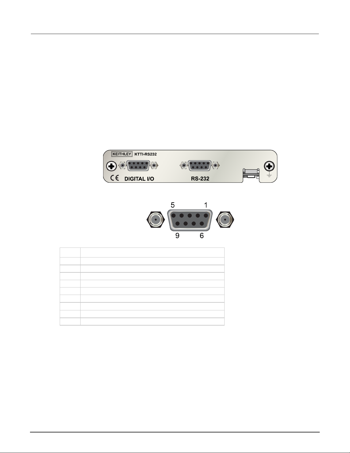
Model DMM6500
Using a remote interface
1
No connection
2
TXD, transmit data
3
RXD, receive data
4
No connection
5
GND, signal ground
6
No connection
7
RTS, ready to send
8
CTS, clear to send
9
No connection
6½ Digit Multimeter User's Manual Section 3:
6. Reconnect the power line cable and any other cables to the rear panel.
7. Turn on the instrument.
Making connections
The RS-232 serial port can be connected to the serial port of a controller using a straight-through
RS232 cable terminated with DB-9 connectors. Do not use a null modem cable.
The serial port uses the transmit (TXD), receiv e (RXD), CTS and RTS (if flow control is enabled), and
signal ground (GND) lines of the RS232 standard. The figure below shows the rear-panel connector
for the RS232 interface. The table below shows the pi nouts for the connector.
Figure 25: KTTI-RS232 panel view
Figure 26: RS-232 panel connector
Pin Description
Additional information
Additional information is available in the KTTI-RS232 Communication and Digital I/O Accessory
Instruction Sheet, part number 0771436XX, where XX is the document revision number.
DMM6500-900-01 Rev. B / August 2019 3-15
Page 44

Section
User's Manual
3: Using a remote interface Model DMM6500 6½ Digit Multimeter
TSP-Link
You can communicate with the instrument using TSP-Link® if a KTTI-TSP communications accessory
card is installed in the instrument.
Keithley Instruments TSP-Link is a high-speed trigger synchronization and communication bus that
test-system builders can use to connect multiple instruments in a master and subordinate
configuration. Once connected, all the instrum ents that are equipped with TSP-Link in a system can
be programmed and operated under the control of the master instrument or instruments. This allow s
the instruments to run tests more quickly because they can be decoupled from frequent computer
interaction. The test system can have multiple master and subordinate groups, which can be used to
handle multidevice testing in parallel. Combining TSP-Link with a flexible programmable trigger model
ensures speed.
Using TSP-Link, multiple instruments are connected and can be used as if they are part of the same
physical unit for simultaneous multichannel testing. The test system can be expanded to include up to
32 TSP-Link-enabled instruments.
The card provides six independently configur able digital input/output lines that can be used to control
external digital circuitry, for example, a handler t hat is used to perform binning operations. The digital
I/O port is a standard female DB-9 connector. You c an also use these lines for triggering. The
instrument can generate output trigger pulses and detect input trigger pulses.
Install the KTTI-TSP accessory card
Figure 27: KTTI-TSP panel view
Unpack and inspect
Make sure to handle the KTTI-TSP card carefully. Always grasp the card by the side edges.
Do not touch board surfaces, components, or areas adjacent to electrical contacts.
Contamination from foreign materials such as dirt, dust, and body oils can substantially
degrade card performance.
3-16 DMM6500-900-01 Rev. B / August 2019
Page 45

Mo
del DMM6500 6½ Digit Multimeter User's Manual Section 3:
Using a remote interface
To unpack and inspect your card:
1. Inspect the box for damage.
2. Open the box.
3. Remove the card and inspect for any obvious sign s of physical damage.
Installation
4. Report any damage to the shipping agent immediat ely.
Slot covers must be installed on unused slots to prevent personal contact with high-voltage
circuits. Failure to recognize and observe standard safety precautions could result in
personal injury or death due to electric shock.
To install the communications card:
1. Turn the instrument off and disconnect the power li ne cord and any other cables connected to the
rear panel.
2. Position the instrument so that you are facing the rear panel.
3. Remove the slot cover plate from the slot on the back of t he inst rument. Retain the plate and
screws for future use.
4. Align the card with the connector toward the inside edge of the slot and slide the card into the
chassis. For the last ¼ inch, press in firmly to mat e the ca rd to the connector.
5. On each side of the card, there is a spring-loaded mo unting screw. Tighten these two screws,
either by hand or with a Phillips-head screwdriver, t o secure the card in the case. Do not
overtighten.
6. Reconnect the power line cable and any other cabl es to the rear panel.
7. Turn on the instrument.
Making connections
The TSP-Link expansion interface uses CAT5 and RJ-45 connectors to connect up to 32 devices.
Additional information
Additional information is available in the KTTI-TSP Communication and Digital I/O Accessory
Instruction Sheet, part number 0771438XX, where XX is the document revision number.
DMM6500-900-01 Rev. B / August 2019 3-17
Page 46

Section
User's Manual
3: Using a remote interface Model DMM6500 6½ Digit Multimeter
Using the web interface
The DMM6500 web interface allows you to make settings and control your instrument through a web
page. The web page includes:
• Instrument status.
• The instrument model, serial number, fir m ware revision, and the last LXI message.
• An ID button to help you locate the instrument.
• A virtual front panel and command interface that you can use to control the instrument.
• Ability to download data from specific reading b uf fers into a CSV file.
• Administrative options and LXI information.
The instrument web page resides in the firmware of the instrument. Changes you make through the
web interface are immediately made in the inst rument.
Connect to the instrument web interface
When the LAN and instrument establish a connection, you can open the web page for the instrument.
To access the web interface:
1. Open a web browser on the host computer.
2. Enter the IP address of the instrument in the address box of the web browser. For example, if the
instrument IP address is 192.168.1.101, enter 192.168.1.101 in the browser address box.
3. Press Enter on the computer keyboard to open the instrument web page.
4. If prompted, enter a user name and password. The default is admin for both.
LAN troubleshooting suggestions
If you are unable to connect to the web interface of the instrument, check the following items:
• The network cable is in the LAN port on the rear panel of the instrument, not one of the
TSP-Link
• The network cable is in the correct port on the computer. The LAN port of a laptop may be
disabled when the laptop is in a docking station.
• The setup procedure used the configuration informat ion for the correct ethernet card.
• The network card of the computer is enabled.
®
ports.
• The IP address of the instrument is compatible wit h the IP address on the computer.
3-18 DMM6500-900-01 Rev. B / August 2019
Page 47

Model DMM6500
Using a remote interface
6½ Digit Multimeter User's Manual Section 3:
• The subnet mask address of the instrument is the same as t he subnet mask address of the
computer.
• Make sure there is no USB cable attached between the instrument and your computer. USB
communications take precedence over LAN.
You can also try restarting the computer and the instrument.
To restart the instrument:
1. Turn the power to the instrument off, and then on.
2. Wait at least 60 seconds for the network configurat i on to be completed.
To set up LAN communications:
1. Press the MENU key.
2. Under System, select Communication.
3. Select the LAN tab.
4. Verify the settings.
If the above actions do not correct the problem, contact your system administrator.
Web interface Home page
Figure 28: DMM6500 web interface
DMM6500-900-01 Rev. B / August 2019 3-19
Page 48

Section
User's Manual
3: Using a remote interface Model DMM6500 6½ Digit Multimeter
The Home page of the instrument provides informati on about the instrument. It includes:
• The instrument model number, manufacturer, serial number, and firmware revision number.
• The TCP Raw Socket number and Telnet Port number.
• The last LXI message. The history link opens the LXI Home page.
• The ID button, which allows you to identify the i nstrument. Refer to Identify the instrument (on
page 3-20).
Identify the instrument
If you have a bank of instruments, you can select the ID button to determine which one you are
communicating with.
Before trying to identify the instrument, make sure you have a remote connection to the instrument.
To identify the instrument:
1. On each instrument in the bank, select MENU, then Communication.
2. Select the LAN tab.
3. On the web interface Home or LXI Home page, selec t the ID button. The button turns green and
the LXI LAN indicator on the instrument LAN tab blinks.
4. Select the ID button again to turn off the ID feature.
Determining the command set you will use
You can change the command set that you use with the DMM6500. The remote command sets that
are available include:
• SCPI: An instrument-specific language built on the SCPI standard.
• TSP: A scripting programming language that cont ai ns instrument-specific control commands that
can be executed from a stand-alone instrument. You can use TSP to send individual commands
or use it to combine commands into scripts.
• SCPI2000: An instrument-specific langu age that allows you to run code developed for Keithley
Instruments Series 2000 instruments.
• SCPI34401: An instrument-specific language that allows you to run code developed for Keysight
Model 34401 instruments.
If you change the command set, reboot the instrument.
You cannot combine the command sets.
As delivered from Keithley Instruments, the DMM 6500 is set to work with the SCPI command set.
3-20 DMM6500-900-01 Rev. B / August 2019
Page 49

Model DMM6500
Using a remote interface
6½ Digit Multimeter User's Manual Section 3:
If you choose the SCPI2000 or SCPI34401 com m and set, you will not have access to some of the
extended ranges and other features that are now avai lable using the default SCPI command set. In
addition, some Series 2000 or Keysight 34401 co de will work differently in the DMM6500 than it did
in the earlier instrument. For information about the differences between the DMM6500 and the
Series 2000, refer to DMM6500 in a Model 2000 A pplication, Keithley Instruments document number
0771466XX. For information about the differences between the DMM6500 and the Keysight 34401,
refer to DMM6500 in a Keysight Model 34401 Appl i cation, Keithley Instruments document number
0771467XX.
To set the command set from the front panel:
1. Press the MENU key.
2. Under System, select Settings.
3. Select the appropriate Command Set.
You are prompted to confirm the change to the command set and reboot.
To verify which command set is selected from a remote interface:
Send the command:
*LANG?
To change to the SCPI command set from a remote interface:
Send the command:
*LANG SCPI
Reboot the instrument.
To change to the TSP command set from a remote interface:
Send the command:
*LANG TSP
Reboot the instrument.
DMM6500-900-01 Rev. B / August 2019 3-21
Page 50

View measurement data .......................................................... 4-3
In this section:
Introduction .............................................................................. 4-1
Equipment required for this example ........................................ 4-1
Device connections .................................................................. 4-1
Basic front-panel measurements .............................................. 4-2
Introduction
This example application makes a 2-wire resist ance measurement using the front panel of the
instrument.
Section 4
Making basic front-panel measurements
Set the function before making other instrument settings. Many of the settings are related to a
specific measure function. The applicati ons in this manual use the order of operations to produce the
best results.
Equipment required for this example
Equipment required to perform this test:
• One DMM6500
• Two insulated banana cables
• One resistor to test; the example uses a resistor with a 9.75 kΩ rating
Device connections
Connect the DMM6500 to the resistor in a 2-wire (local sense) configuration. In this configuration, the
device is connected between the INPUT HI and INP UT LO terminals.
Page 51

Section
User's Manual
4: Making basic front-panel measurements Model DMM6500 6½ Digit Multimeter
To make the connections:
1. Power off the DMM6500.
2. Connect the test leads to the front-panel INP UT HI and INPUT LO terminals, as shown in the
following figure.
3. Connect the test leads to the resistor.
Figure 29: DMM6500 front-panel 2-wire resistance measurement
Basic front-panel measurements
The following procedures show you how to make a measurement, access settings for the
measurement, and view measurement data in a reading buffer.
You can make measurements continuously or man ually. When you make continuous measurements,
the instrument makes measurements as quickly as possible. When you make manual measurements,
the instrument makes measurements when you press the TRIGGER key.
To make a measurement from the front panel:
1. Press the POWER switch on the front panel to turn on the instrument.
2. Make sure the TERMINALS switch is set to FRONT.
3. From the Functions swipe screen, select 2W Ω. Measurements begin to display on the top half of
the home screen.
4. If measurements are not displayed, press the TRIGGER key for a few second s and select
Continuous Measurement.
4-2 DMM6500-900-01 Rev. B / August 2019
Page 52

Model DMM6500
panel measurements
6½ Digit Multimeter User's Manual Section 4: Making basic front-
To change the measure settings:
1. Press the MENU key.
2. Under Measure, select Settings.
3. Select Display Digits.
4. Select 3.5 Digits.
5. Press the HOME key. The measurement now shows 3½ digits.
To make a single measurement:
1. Press the front-panel TRIGGER key for a few sec onds.
2. Select Manual Trigger Mode.
3. Press the TRIGGER key to initiate a single reading using the selected measure function.
Figure 30: Basic measurement test results
View measurement data
You can view data from the reading buffers through t he front panel using the Reading Table. The
Reading Table displays the following information:
• Index: The sequential number of the reading.
• Time: The data and time of the reading.
• Reading: The data that was measured.
• Extra: Only displayed for buffers that are set to Full. The extra value that i s stored with a reading,
such as the ratio component of a DCV ratio mea sur ement.
• Terminal: The terminals (Front or Rear) that were used to make the readings. When using Rear
terminals with a switch card installed and you clos e a channel on that switch card, the Terminal is
listed as Rear with the channel number of the closed channels in parenthesis. For example, if you
close channel 3, Terminal displays Rear (3).
DMM6500-900-01 Rev. B / August 2019 4-3
Page 53

Section
User's Manual
4: Making basic front-panel measurements Model DMM6500 6½ Digit Multimeter
If you select a data point, additional detail about that data point is displayed, including the function,
math, and limits.
To jump to a specific spot in the data, select the menu in the upper left and select Jump to Index.
The selected data point is displayed at the top of t he reading table.
To save the data, select the menu in the upper left and select Save to USB.
When TERMINALS is set to REAR, you can filter the data using channels and watch channels. The
options include:
• Filter by Watch Channels (Active Buffer): Filters the data by watch channels. Aft er selecting
this option, select Edit Watch Channels to select specific channels.
• Edit Watch Channels (Active Buffer): Select which channels are watched channels.
• Filter by Channels: Allows you to limit the data in the readi ng table. After selecting Filter by
Channels, select Edit Channels to specify the channels to display.
• Edit Channels: Allows you to select the channels that are displayed in the reading table.
• No Filtering: Removes filters from the reading table and displays all data for the selected buffer.
Using the front panel to view the contents of a reading buffer:
1. Press the MENU key.
2. Under Views, select Reading Table. Data for the acti ve reading buffer is displayed.
Figure 31: Reading table
3. To display data for a different reading buffer, sele ct the new buffer.
4. To view details for a specific data point, swipe the table up or down and select the data point to
view the Reading Details. If there are many data poin ts, select an area on the reading preview
graph in the upper right corner of the screen to get close r to the data you want, and then scroll to
the data point. You can also select the menu and select Jump to Index to go to a specific point.
5. Press the HOME key to return to the home screen.
4-4 DMM6500-900-01 Rev. B / August 2019
Page 54

Measuring DCV with high accurac y ......................................... 5-3
In this section:
Introduction .............................................................................. 5-1
Equipment required .................................................................. 5-1
Device connections .................................................................. 5-1
Introduction
This example application demonstrates how to use a DMM6500 to make high-accuracy DC voltage
measurements.
Section 5
Measuring DC voltage with high accuracy
This type of test is often done in metrology laborat ories where high accuracy is required for calibration
and verification.
Equipment required
• One DMM6500
• One computer set up for communication with the i nstrument
• Two insulated banana cables
• One device or component to be tested
Device connections
This example uses the DMM6500 to measure DC voltage using either the front or rear input terminals.
Both the front and rear-panel input terminals are safety banana j acks.
You must use either the front or the rear terminals. You cannot mix the front and rear connections.
Make sure that the front-panel TERMINALS switch is set to the terminals you are using. The light for
FRONT or REAR indicates which terminals are being used.
Page 55

Section
User's Manual
5: Measuring DC voltage with high acc uracy Model DMM6500 6½ Digit Multimeter
Connecting devices to the instrument:
1. Connect the test leads to the INPUT HI and LO terminals.
2. Connect the test leads to the device under test (DUT).
Figure 32: Front-panel connections
Figure 33: Rear-panel connections
To prevent electric shock, test connections mu st be configured such that the user cannot
come in contact with test leads or any devi ce u n der test (DUT) that is in contact with the
conductors. It is good practice to disconnect DUTs from the instrument before po wering the
instrument. Safe installation requires proper shields, barriers, and grounding to prevent
contact with test leads.
5-2 DMM6500-900-01 Rev. B / August 2019
Page 56

Model DMM6500
Measuring DC voltage with high accuracy
6½ Digit Multimeter User's Manual Section 5:
There is no internal connection between protective earth (safety ground) and the LO
terminals of the DMM6500. Therefore, hazardous voltages (more than 30 V
LO terminals. This can occur when the instrument is operating in any mode. To prevent
hazardous voltage from appearing on the LO terminals, connect the LO terminal to protectiv e
earth (safety ground) if your application allows it. You can connect the LO terminal to the
chassis ground terminal on the front panel or the chassis ground screw terminal on the rear
panel. Note that the front-panel terminals are isolated from the rear-panel terminals.
Therefore, if you are using the front-panel terminals, ground to the front-panel LO termi nal . I f
you are using the rear-panel terminals, ground to the rear-panel LO terminal. Failure to follow
these guidelines can result in injury, death, or instrument damage.
Measuring DCV with high accuracy
This application demonstrates how to use the DMM 6500 to make high-accuracy DC voltage
measurements. You can make the measurements from the front-panel interface or over the remote
interface using SCPI code or TSP code. For information about setting up remote communications,
see Remote communications interfaces (on page 3-1
).
) can appear on
RMS
For this application, you will:
• Restart the instrument.
• Verify that the DC voltage function is selected.
• Set the range to 10 V.
• Set the integration rate to 1 power line cycle (PLC) at 60 Hz line frequency; 1 PLC provides an
aperture of 16.67 ms.
• Turn on autozero. This allows the instrument to opt imize the accuracy of readings by checking
reference measurements.
• Enable a repeating filter with a count of 100. This reduce s noise error because the results are
more stable when the measurements are averaged.
• Generate readings from the front panel or the remote interface.
DMM6500-900-01 Rev. B / August 2019 5-3
Page 57

Section
User's Manual
5: Measuring DC voltage with high acc uracy Model DMM6500 6½ Digit Multimeter
Using the front panel
To run this example from the front panel:
1. Press the POWER switch on the front panel to turn on the instrument.
2. Select the REAR terminals.
3. On the FUNCTIONS swipe screen, select DCV.
4. On the top half of the home screen, set the Range to 10 V .
5. Swipe to the SETTINGS screen.
6. Set the Rate to 1.
7. Select OK.
8. Verify that Auto Zero is selected.
9. Press the MENU key.
10. Under Measure, select Calculations.
11. Set Filter to On.
12. Select the Settings icon.
13. Set the Type to Repeat.
14. Set the Count to 100.
15. Select OK.
16. Press the HOME key.
If measurements are not updating, press the TRIGGER key for a few seconds. Verify that the trigger
mode is set to Continuous Measurement.
The measurements are displayed in the top area of t he hom e screen. There are a few seconds
between readings.
With a repeating filter count of 100 and NPLC of 1, the measurement cycle time is slow but accurate.
By reducing the values of these settings, you can get faster but less accurate readings. The balance
between speed and accuracy depends on the needs of your specific application.
5-4 DMM6500-900-01 Rev. B / August 2019
Page 58

Model DMM6500
high accuracy
*RST
reading is returned
6½ Digit Multimeter User's Manual Section 5: Measuring DC voltage with
Using SCPI commands
This sequence of SCPI commands makes a single high-accuracy DC voltage measurement.
You may need to make changes so that this code will run in your programming environment. In the
table, the SCPI commands have a light gray backgr ound.
Send the following commands for this example application:
Commands Descriptions
:SENS:FUNC "VOLT:DC"
:SENS:VOLT:RANG 10
:SENS:VOLT:INP AUTO
:SENS:VOLT:NPLC 10
:SENS:VOLT:AZER ON
:SENS:VOLT:AVER:TCON REP
:SENS:VOLT:AVER:COUN 100
:SENS:VOLT:AVER ON
:READ?
Reset the DMM6500
Set the instrument to measure DC vol tage
Set the measure range to 10 V
Set the input impedance to automatic so the instrument
selects 10 Ω for the 10 V range
Set the integration rate (NPLCs) t o 10
Enable autozero
Set the averaging filter type to repeating
Set the filter count to 100
Enable the filter
Read the voltage value; it is a few sec onds before the
Using TSP commands
The following TSP code is designed to be run from Keithley Instruments Test Script Builder (TSB).
TSB is a software tool that is available from tek.com/keithley
code and develop scripts for TSP-enabled instruments. Information about how to use TSB is in the
online help for TSB and in the “Introduction to TS P operation” section of the Model DMM6500
Reference Manual.
To use other programming environments, you may need to make changes to the example TSP code.
By default, the DMM6500 uses the SCPI command s et. You must select the TSP command set
before sending TSP commands to the instrument.
To enable TSP commands:
1. Press the MENU key.
2. Under System, select Settings.
3. Set the Command Set to TSP.
4. At the prompt to reboot, select Yes.
This sequence of TSP commands makes a single hig h-accuracy DC voltage measurement. After the
code executes, the data is displayed in the Instrum ent Console of Test Script Builder.
. You can install and use TSB to write
DMM6500-900-01 Rev. B / August 2019 5-5
Page 59

Section
User's Manual
4.999985
33.542816
10
On
On
4.999982
0.335426
10
Off
On
4.999979
0.035426
1
Off
On
4.999990
0.017023
1
Off
Off
5: Measuring DC voltage with high acc uracy Model DMM6500 6½ Digit Multimeter
Send the following commands for this example application:
-- Reset the instrument to the default settings.
reset()
-- Set the measure function to DC voltage.
dmm.measure.func = dmm.FUNC_DC_VOLTAGE
-- Set the measurement range to 10 V.
dmm.measure.range = 10
-- Set the number of power line cycles to 10.
dmm.measure.nplc = 10
-- Set the input impedance to auto so it selects 10 Gohm for the 10 V range.
dmm.measure.inputimpedance = dmm.IMPEDANCE_AUTO
-- Enable autozero.
dmm.measure.autozero.enable = dmm.ON
-- Set the averaging filter type to repeating.
dmm.measure.filter.type = dmm.FILTER_REPEAT_AVG
-- Set filter count to 100.
dmm.measure.filter.count = 100
-- Enable the filter.
dmm.measure.filter.enable = dmm.ON
-- Read the voltage value.
print(dmm.measure.read())
Test results
The following table shows the trade-off betwee n accuracy and measurement speed based on the
integration rate (NPLC), averaging filter, and autozero settings. The first row of data is measured
using the setup documented in this example. The ot her rows show the results as the integration rate,
filter, and autozero settings are changed.
DC voltage
Measurement time
(seconds)
Figure 34: DC voltage high-accuracy test results
Integration rate (NPLC) Filter Auto Zero
5-6 DMM6500-900-01 Rev. B / August 2019
Page 60

Measuring 4-wire resistance with offset compensation ............ 6-4
Measuring 4-wire resistance with offset compensation
In this section:
Introduction .............................................................................. 6-1
Equipment required .................................................................. 6-2
Device connections .................................................................. 6-2
Introduction
This application example demonstrates how t o use the DMM6500 to accurately measure resistance.
Section 6
Typically, when resistance measurements are made using the 2-wire method, the instrument sources
current through the test leads and the device under test (DUT). The voltage is measured and the
resistance is calculated.
It is difficult to obtain accurate 2-wire resistance measurements when the DUT has a resistance value
of less than 100 Ω. Typical lead resistances are from 1 mΩ to 10 mΩ. When the 2-wire method is
applied to low-resistance measurements, t here i s a small but significant voltage drop across the
resistance of each test lead. The voltage mea sur ed by the instrument is not the same as the voltage
directly across the DUT.
The 4-wire method is preferred for low-resist ance measurements. With this configuration, the test
current is sourced through the DUT using one set of test leads, while a second set of SENSE leads
measures the voltage across the DUT. Connect the voltage-sensing leads as close to the DUT as
possible to avoid including the resistance of the test leads in the measurement.
Thermoelectric voltages (EMFs) can seriously affect low-resistance measurement accuracy. The
DMM6500 can apply the offset-compensated ohms method (OCOMP), which makes one normal
resistance measurement and one using the lowest cu rrent source setting to eliminate EMFs.
For this example, you use a 20 Ω resistor. Fixed measurement ranges are applied to optimize
scanning speed and OCOMP is applied to correct for any EMF effects.
For comprehensive information on 4-wire resist ance measurements, thermoelectric EMFs, and offset
compensation methods, see the Low Level Measurements Handbook, available on tek.com/keithley
.
Page 61

Section
User's Manual
6: Measuring 4-wire resistance with of fset compensation Model DMM6500 6½ Digit Multimeter
Equipment required
• One DMM6500
• One computer set up for communication with the i nstrument
• Four insulated banana cables
• One device to be tested (the application shown uses a 20 Ω resistor)
Device connections
This example application uses the DMM6500 to perf orm a 4-wire resistance-device measurement
using offset compensation. Both the front and rear-panel connections are safety banana jacks. You
can use either the front or the rear input terminal s.
You must use either the front or the rear terminals. You cannot mix the front and rear connections.
Make sure that the front-panel TERMINALS switch is set to the terminals you are using. The l i ght for
FRONT or REAR indicates which terminals are being used.
To use the 4-wire connection method:
1. Connect one set of test leads to the INPUT HI and INPUT LO terminals.
2. Connect the other set of test leads to the SENSE HI and SENSE LO terminals.
Figure 35: Front-panel connections for 4-wire resistance measurements
6-2 DMM6500-900-01 Rev. B / August 2019
Page 62
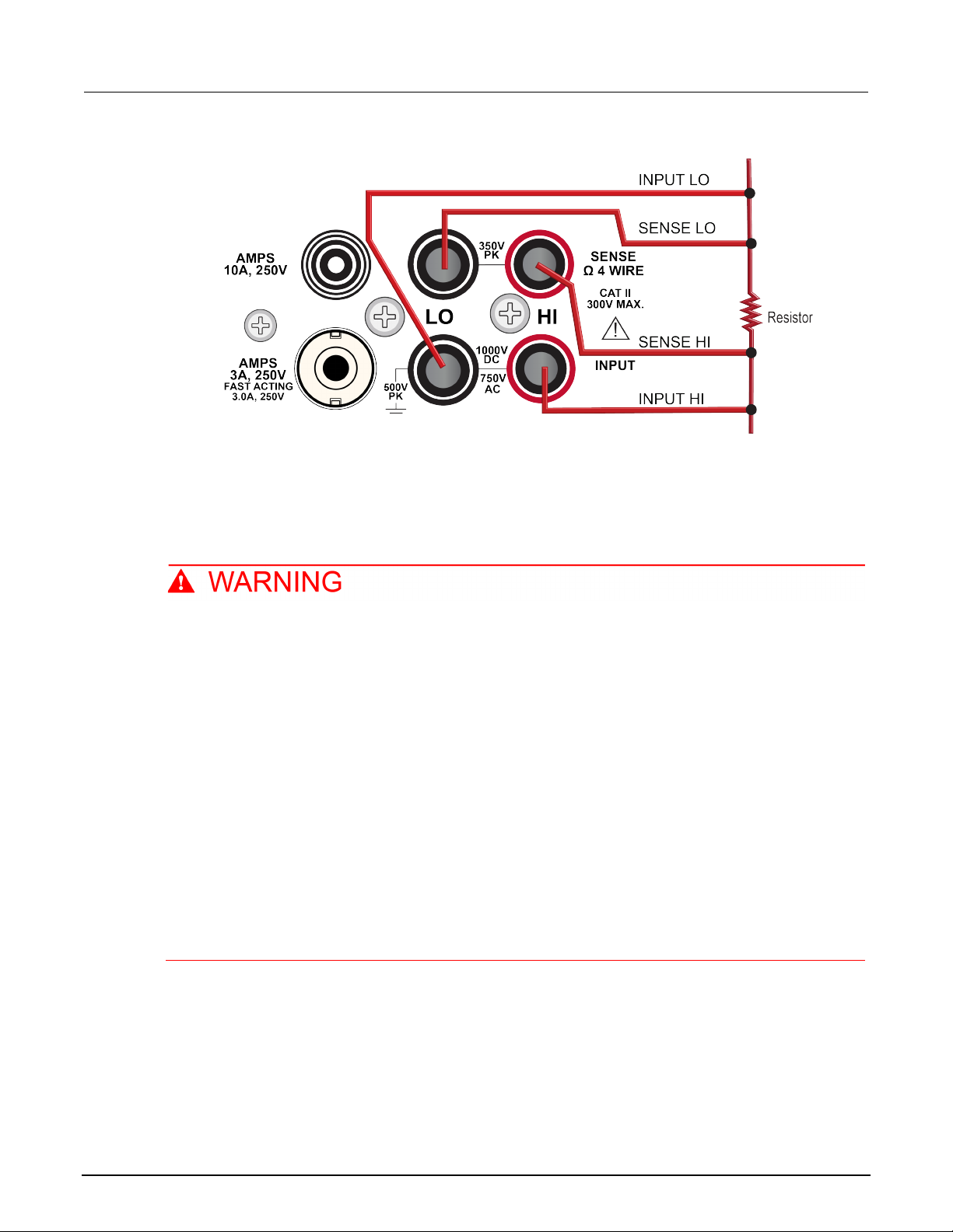
Model DMM6500
wire resistance with offset compensation
6½ Digit Multimeter User's Manu al Section 6: Measuring 4-
Figure 36: Rear-panel connections for 4-wire resistance measurements
3. Connect the INPUT HI and SENSE HI connections t o one of the device-under-test (DUT) leads.
Connect the sense connection as close to the DUT as possible.
4. Connect the INPUT LO and SENSE LO to the other DUT l ead. Connect the sense connection as
close to the DUT as possible.
To prevent electric shock, test connections mu st be configured such that the user cannot
come in contact with test leads or any device un d er test (DUT) that is in contact with the
conductors. It is good practice to disconnect DUTs from the instrument before po wering the
instrument. Safe installation requires proper shields, barriers, and grounding to prevent
contact with test leads.
There is no internal connection between protective earth (safety ground) and the LO
terminals of the DMM6500. Therefore, hazardous voltages (more than 30 V
) can appear on
RMS
LO terminals. This can occur when the instrument is operating in any mode. To prevent
hazardous voltage from appearing on the LO terminals, connect the LO terminal to protectiv e
earth (safety ground) if your application allows it. You can connect the LO terminal to the
chassis ground terminal on the front panel or the chassis ground screw terminal on the rear
panel. Note that the front-panel terminals are isolated from the rear-panel terminals.
Therefore, if you are using the front-panel terminals, ground to the front-panel LO termi nal . I f
you are using the rear-panel terminals, ground to the rear-panel LO terminal. Failure to follow
these guidelines can result in injury, death, or instrument damage.
DMM6500-900-01 Rev. B / August 2019 6-3
Page 63

Section
nual
6: Measuring 4-wire resistance with of fset compensation Model DMM6500 6½ Digit Multimeter User's Ma
Measuring 4-wire resistance with offset compensation
This application demonstrates how to use the DMM 6500 to measure the resistance of a device or
component. You can make this measurement from the front panel or over the remote interface using
SCPI or TSP code. For information about setting up remote communications, see
communications interfaces (on page 3-1).
For this application, you:
• Reset the instrument.
• Select the 4-wire resistance function. This method eliminates the effect of the lead resistance on
measurement accuracy.
• Enable offset compensation.
Remote
• Make measurements from the front panel or the remote interface.
Using the front panel
Auto Zero is automatically set to On, and NPLC is automatically set to 1.
To set up the application from the front panel:
1. Press the POWER switch on the front panel to turn on the instrument.
2. On the FUNCTIONS swipe screen, select 4W Ω to select t he 4-wire resistance measure function.
3. Press the MENU key.
4. Under Measure, select Settings.
5. Set Range to 10kΩ.
6. Select
7. P
The measurement readings are displayed in the t op area of the home screen.
Offset Compensation
ress the HOME key.
and select On.
6-4 DMM6500-900-01 Rev. B / August 2019
Page 64

Model DMM6500
wire resistance with offset compensation
*RST
Read the resistance value.
6½ Digit Multimeter User's Manual Section 6: Measuring 4-
Using SCPI commands
This sequence of SCPI commands measures the resistance of a device or component.
You may need to make changes so that this code will run in your programming environment. In the
following table, the SCPI commands have a li ght gray background.
Send the following commands for this example application:
Commands Descriptions
:SENS:FUNC "FRES"
:SENS:FRES:RANG: AUTO ON
:SENS:FRES:OCOM ON
:SENS:FRES:AZER ON
:SENS:FRES:NPLC 1
:READ?
Reset the DMM6500.
Set the function to 4-wire measurement.
Enable autorange.
Enable offset compensation.
Enable autozero.
Set NPLC to 1.
Using TSP commands
The following TSP code is designed to be run from Keithley Instruments Test Script Builder (TSB).
TSB is a software tool that is available from tek.com/keithley
code and develop scripts for TSP-enabled instruments. Information about how to use TSB is in the
online help for TSB and in the “Introduction to TSP operat i on” section of the Model DMM6500
Reference Manual.
To use other programming environments, you may need to make changes to the example TSP code.
By default, the DMM6500 uses the SCPI command s et. You must select the TSP command set
before sending TSP commands to the instrument.
To enable TSP commands:
1. Press the MENU key.
2. Under System, select Settings.
3. Set the Command Set to TSP.
4. At the prompt to reboot, select Yes.
This sequence of TSP commands initiates one re sistance reading. After the code is executed, the
data is displayed in the Instrument Console of Test Script Builder.
. You can install and use TSB to write
DMM6500-900-01 Rev. B / August 2019 6-5
Page 65

Section
User's Manual
Off
19.992460878
On
19.991394395
6: Measuring 4-wire resistance with of fset compensation Model DMM6500 6½ Digit Multimeter
Send the following commands for this example application:
-- Reset the Model DMM6500 to the default settings.
reset()
-- Set the measure function to 4-wire resistance.
dmm.measure.func = dmm.FUNC_4W_RESISTANCE
-- Enable autorange.
dmm.measure.autorange = dmm.ON
-- Enable autozero.
dmm.measure.autozero.enable = dmm.ON
-- Enable offset compensation.
dmm.measure.offsetcompensation.enable = dmm.ON
-- Set the number of power line cycles to 1.
dmm.measure.nplc = 1
-- Read the resistance value.
print(dmm.measure.read())
Test results
The results of a low-resistance measurement test using a 20 Ω resistor are shown in the table below.
For example, if the resistor specification has a tol erance of ±0.1% and a temperature coefficient of
±15 ppm per °C, a compliant resistor measures between 19.97 Ω and 20.03 Ω.
Offset compensation Resistance
Figure 37: 4-wire resistance test results
6-6 DMM6500-900-01 Rev. B / August 2019
Page 66

Sample temperatures at a specific time interval ....................... 7-4
In this section:
Introduction .............................................................................. 7-1
Equipment required .................................................................. 7-1
Device connections .................................................................. 7-2
Introduction
This application example demonstrates how to use the DMM6500 to log temperature measurement
data from multiple scan-card channels, one every mi nute for 24 hours. The data is saved to a USB
flash drive.
Section 7
Scanning temperature at a set time interval
During production or storage, the temperature of the testing environment can be important. You can
use the DMM6500 to monitor temperature at a fi xed time interval for an extended period.
This application requires a Keithley Instrum ents 2001-TCSCAN card. The 2001-TCSCAN provi des
connections for up to nine channels of thermocouple temperature measurements.
For this application example, the card is connected to a type K thermocouple on each channel.
Equipment required
• One DMM6500
• One 2001-TCSCAN card
• One computer set up for communication with the i nstrument
• One USB flash drive
• One device or component to be tested
Page 67

Section
User's Manual
7: Scanning temperature at a set time int er val Model DMM6500 6½ Digit Multimeter
Device connections
The 2001-TCSCAN scan provides up to nine chan nels of thermocouple temperature measurements.
For this example, each channel of the card is connected to a type K thermocouple. The card is then
inserted into the rear of the DMM6500.
To set up and install the 2001-TCSCAN card:
1. Power off the instrument.
2. Make connections to the 2001-TCSCAN card as shown in the following figure.
Figure 38: 2001-TCSCAN card
7-2 DMM6500-900-01 Rev. B / August 2019
Page 68

Model DMM6500
Scanning temperature at a set time int erval
6½ Digit Multimeter User's Manual Section 7:
3. Install the 2001-TCSCAN card into the access ory card slot of the DMM6500. For information on
installing the 2001-TCSCAN card, refer to the Model 2001-TCSCAN Scanner Card for use with
the DMM6500 User's Manual, part number 2001 -TCSCAN-900-01.
Figure 39: DMM6500 rear panel with TCSCAN card installed
DMM6500-900-01 Rev. B / August 2019 7-3
4. Power on the instrument.
5. Set the TERMINALS switch on the front panel of the inst rument to REAR.
To prevent electric shock, test connections mu st be configured such that the user cannot
come in contact with test leads or any device un d er test (DUT) that is in contact with the
conductors. It is good practice to disconnect DUTs from the instrument before po wering the
instrument. Safe installation requires proper shields, barriers, and grounding to prevent
contact with test leads.
Page 69

Section
User's Manual
7: Scanning temperature at a set time int er val Model DMM6500 6½ Digit Multimeter
There is no internal connection between protective earth (safety ground) and the LO
terminals of the DMM6500. Therefore, hazardous voltages (more than 30 V
LO terminals. This can occur when the instrument is operating in any mode. To prevent
hazardous voltage from appearing on the LO terminals, connect the LO terminal to protectiv e
earth (safety ground) if your application allows it. You can connect the LO terminal to the
chassis ground terminal on the front panel or the chassis ground screw terminal on the rear
panel. Note that the front-panel terminals are isolated from the rear-panel terminals.
Therefore, if you are using the front-panel terminals, ground to the front-panel LO termi nal . I f
you are using the rear-panel terminals, ground to the rear-panel LO terminal. Failure to follow
these guidelines can result in injury, death, or instrument damage.
Sample temperatures at a specific time interval
This example application uses the DMM6500 to sca n a set of channels, measuring temperature at a
fixed interval. You can control the instrument f rom the front panel or over the remote interface using
SCPI code or TSP code. For information about setting up remote communication s, see
communications interfaces (on page 3-1).
) can appear on
RMS
Remote
For this application, you will:
• Power on the instrument.
• Configure channels two through ten to measure temperature using type K thermocouples and the
internal reference junction.
• Use the Scan menu to set up a temperature scan of channels 2 to 10 that occurs every minute for
24 hours for a total of 1440 scans.
Using the front panel
To set up the application through the front panel:
1. Press the POWER button on the front panel to turn on the instrument.
2. Select the REAR terminals.
3. Swipe to the SCAN screen, then select Build Scan. The SCAN sc reen opens.
4. Select the + button.
5. Select channel 1, then select OK.
6. On the Measure Functions dialog box, select Temperature.
7. On the settings tab, set the Transducer to CJC 2001.
8. Select the + button.
9. Select channels 2 through 10 and select OK.
10. From the Function dialog box, select Temperature.
7-4 DMM6500-900-01 Rev. B / August 2019
Page 70

Model
DMM6500 6½ Digit Multimeter User's Manual Section 7:
Scanning temperature at a set time int erval
11. On the Settings tab, select the following:
Transducer: TC
Thermocouple: K
Unit: Celsius
NPLC: 1
12. Select the Scan tab.
13. Set the Scan Count to 1440 (24 hours * 60 minutes).
14. Set the Scan to Scan Interval to 60 s.
15. Set Export to USB to After Each Scan.
16. Set the Filename to scan24hr and select OK.
17. Select OK on the File Content dialog box.
18. Set Power Loss Restart to On.
19. Select Start on the SCAN screen.
20. To view the results, select View Scan Status, which opens the SCAN swipe screen on the home
screen.
Using SCPI commands
This sequence of SCPI commands executes a therm ocouple-based temperature scan every minute
for 24 hours.
You may need to make changes so that this code run s in your programming environment. In the
following table, the SCPI commands have a li ght gray background.
Make sure the TERMINALS switch is set to REAR.
Send the following commands for this example application:
The scan count is 24 * 60; the channel count (chanCount) is 10. The total number of readings
(totalRdgs) is scanCount * chanCount.
DMM6500-900-01 Rev. B / August 2019 7-5
Page 71

Section
Manual
*RST
completes
7: Scanning temperature at a set time int er val Model DMM6500 6½ Digit Multimeter User's
Commands Descriptions
TRAC:CLE "defbuffer1"
TRAC:POIN 12960, "defbuffer1"
FUNC "TEMP", (@1:10)
TEMP:UNIT CELS, (@1:10)
TEMP:TRAN CJC2001, (@1)
TEMP:TRAN TC, (@2:10)
TEMP:TC:TYPE K, (@2:10)
TEMP:TC:RJUN:RSEL EXT, (@2:10)
TEMP:NPLC 1, (@2:10)
ROUT:SCAN:INT 60
ROUT:SCAN:COUN:SCAN 1440
ROUT:SCAN:CRE (@1:10)
ROUT:SCAN:EXP "/usb1/scan24hr", SCAN, ALL
ROUT:SCAN:REST ON
INIT
*WAI
TRAC:DATA? 1, totalRdgs, "defbuffer1\", READ
Reset the DMM6500
Clear the data buffer
Set the scan count to 12,960
Set the function to temperature
Set up all channels to use degrees
Celsius
Set up channel 1 reference junction
Set the transducer type to thermocouple
Set thermocouple type to K
Set the reference junction to extern al
Set NPLC to 1
Set the scan-to-scan delay to 60 seconds
Set the scan count to 1440 (24 hr * 60 s)
Set the scan list
Prepare the scan to export the buffer to
the USB flash drive after each scan
Enable restart on power loss
Start the scan
Suspend the scan
Return data from the buffer after the scan
Using TSP
The following TSP code is designed to be run from Keithley Instruments Test Script Builder (TSB).
TSB is a software tool that is available from tek.com/keithley
code and develop scripts for TSP-enabled instruments. Information about how to use TSB is in the
online help for TSB and in the “Introduction to TSP operat i on” section of the Model DMM6500
Reference Manual.
To use other programming environments, you may need to make changes to the example TSP code.
By default, the DMM6500 uses the SCPI command s et. You must select the TSP command set
before sending TSP commands to the instrument.
To enable TSP commands:
1. Press the MENU key.
2. Under System, select Settings.
3. Set the Command Set to TSP.
4. At the prompt to reboot, select Yes.
. You can install and use TSB to write
7-6 DMM6500-900-01 Rev. B / August 2019
Page 72

Model DMM6500
Scanning temperature at a set time int erval
6½ Digit Multimeter User's Manual Section 7:
This sequence of TSP commands makes a series of t em perature measurements. After the code
executes, the data is displayed in the Instrument Console of Test Script Builder.
Make sure the TERMINALS switch is set to REAR.
Send the following commands for this example application:
-- Reset the instrument to the default settings.
reset()
-- Establish variables to make a measurement every 60 seconds 1440 times (24 hours).
local scanCnt = 24 * 60 -- 1440 minutes = 24 hours
local chanCnt = 10
local totalRdgs = scanCnt * chanCnt
-- Empty the buffer and set it to the capacity calculated by totalRdgs.
defbuffer1.clear()
defbuffer1.capacity = totalRdgs
-- Set up the channels to measure temperature using type K thermocouples using internal
reference junction.
channel.setdmm("1:10", dmm.ATTR_MEAS_FUNCTION, dmm.FUNC_TEMPERATURE)
channel.setdmm("1:10", dmm.ATTR_MEAS_UNIT, dmm.UNIT_CELSIUS)
channel.setdmm("1:10", dmm.ATTR_MEAS_NPLC, 1)
channel.setdmm("1:10", dmm.ATTR_MEAS_DIGITS, dmm.DIGITS_5_5)
channel.setdmm("1", dmm.ATTR_MEAS_TRANSDUCER, dmm.TRANS_CJC2001)
channel.setdmm("2:10", dmm.ATTR_MEAS_TRANSDUCER, dmm.TRANS_THERMOCOUPLE)
channel.setdmm("2:10", dmm.ATTR_MEAS_THERMOCOUPLE, dmm.THERMOCOUPLE_K)
channel.setdmm("2:10", dmm.ATTR_MEAS_REF_JUNCTION, dmm.REFJUNCT_EXTERNAL)
-- Set up the scan; channel 2 is first available channel on a 2001-TCSCAN card.
scan.create("2:10")
scan.scancount = scanCnt
-- Set the amount of time for each scan.
scan.scaninterval = 60.0
-- Write the data to a USB flash drive at the end of the scan.
scan.export("/usb1/scan24hr", scan.WRITE_AFTER_SCAN, buffer.COL_ALL)
-- Enable scan restart on power loss
scan.restart = scan.ON
-- Start the scan.
trigger.model.initiate()
waitcomplete()
-- Get the data.
printbuffer(1, defbuffer1.n, defbuffer1)
DMM6500-900-01 Rev. B / August 2019 7-7
Page 73

Section
User's Manual
7: Scanning temperature at a set time int er val Model DMM6500 6½ Digit Multimeter
Test results
The following figures show a sample graph and final test measurement for this application.
Figure 40: DMM6500 graph of temperature measurement s
Figure 41: DMM6500 final temperature measur ement
7-8 DMM6500-900-01 Rev. B / August 2019
Page 74

Resistor grading and binning test ............................................. 8-3
In this section:
Introduction .............................................................................. 8-1
Equipment required .................................................................. 8-1
Device connections .................................................................. 8-1
Introduction
This application example demonstrates how to use the DMM6500 to perform benchtop binning
operations. It uses the trigger model and digital I/O to control external component-handling devices.
Section 8
Grading and binning resistors
The DMM6500 can do simple pass-or-fail testing as well as grading and sorting. Grading resistors is a
common application that is done by monitoring m ultiple limits until the first failure. Binning resistors is
also common, but unlike grading, binning inv olves monitoring limits until the first pass is received.
Equipment required
• One DMM6500
• One computer set up for communication with the i nstrument
• One device or component to be tested
Device connections
This example application uses a DMM6500 to pe rf orm benchtop binning operations. Output signals
(grading results) are sent from the instrument to the component handler, which bins the devices.
The figure below shows the rear-panel connections from the DMM6500 to the test fixture and the
digital lines to the component handler. The optional GPIB communication card connects the controller
and the component handler.
Digital lines and GPIB communications requi re t he K TTI-GPIB communications accessory card.
Page 75
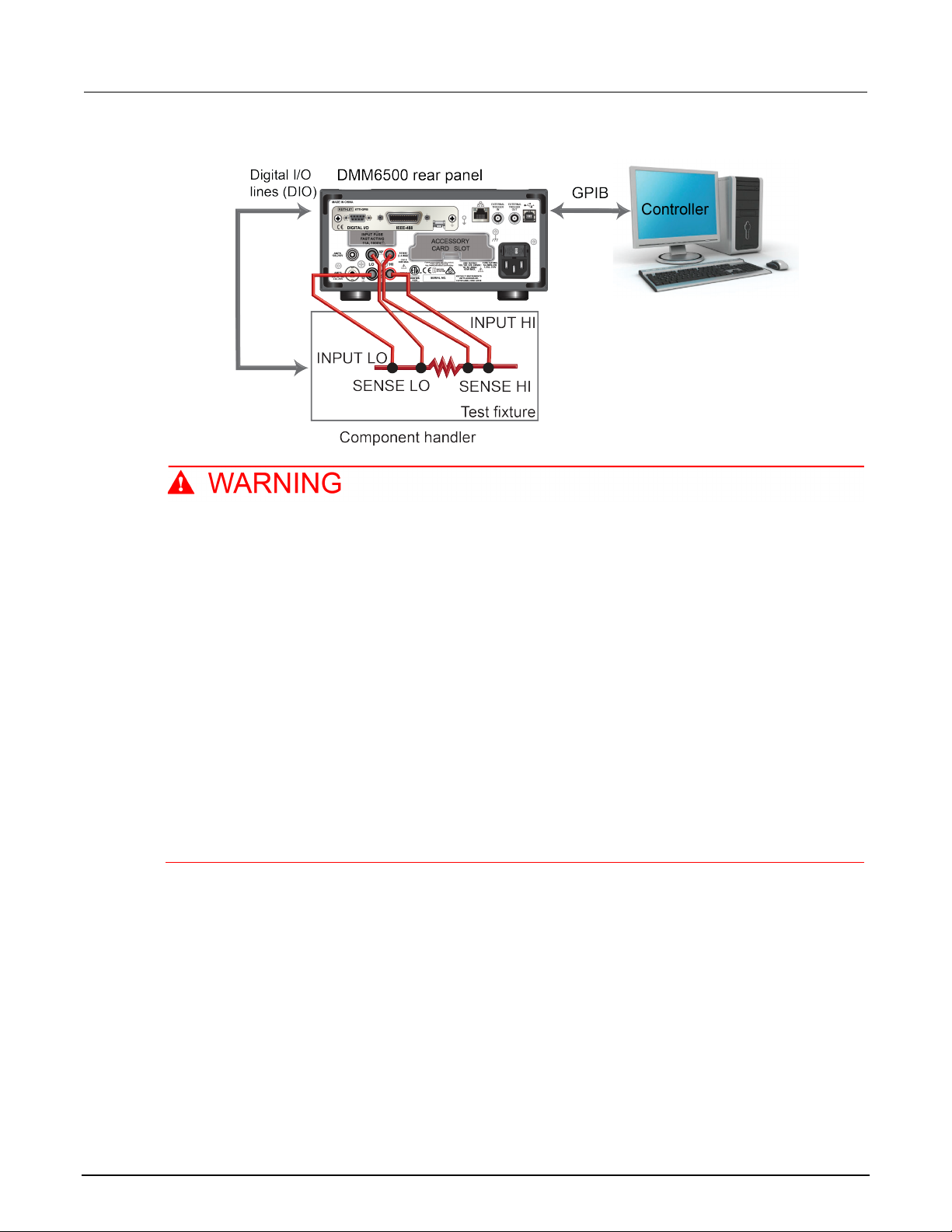
Section
User's Manual
8: Grading and binning resistors Model DMM6500 6½ Digit Multimeter
Figure 42: Device connections for component binning
To prevent electric shock, test connections mu st be configured such that the user cannot
come in contact with test leads or any device un d er test (DUT) that is in contact with the
conductors. It is good practice to disconnect DUTs from the instrument before po wering the
instrument. Safe installation requires proper shields, barriers, and grounding to prevent
contact with test leads.
There is no internal connection between protective earth (safety ground) and the LO
terminals of the DMM6500. Therefore, hazardous voltages (more than 30 V
) can appear on
RMS
LO terminals. This can occur when the instrument is operating in any mode. To prevent
hazardous voltage from appearing on the LO terminals, connect the LO terminal to protectiv e
earth (safety ground) if your application allows it. You can connect the LO terminal to the
chassis ground terminal on the front panel or the chassis ground screw terminal on the rear
panel. Note that the front-panel terminals are isolated from the rear-panel terminals.
Therefore, if you are using the front-panel terminals, ground to the front-panel LO termi nal . I f
you are using the rear-panel terminals, ground to the rear-panel LO terminal. Failure to follow
these guidelines can result in injury, death, or instrument damage.
8-2 DMM6500-900-01 Rev. B / August 2019
Page 76

Model DMM6500
Grading and binning resistors
6½ Digit Multimeter User's Manual Section 8:
Resistor grading and binning test
This resistance-grading ap pl i cati on uses limit tests to inspect a single resistor under test against
multiple limits until the first failure occurs. When the resistor fails, it is placed into a designated
resistance tolerance bin, as defined by the li m i ts.
Resistors are placed into bins based on the bit patterns that are assigned to the limits. In this example,
the DMM6500 GradeBinning trigger model template is used to simplify the application. This trigger
model template grades components into four tolerance levels (for example, 20%, 10%, 5%, and 1%)
as defined by limits 1 to 4. A single spot measurement is inspected against multiple limits, which
tighten progressively around the same nominal value. Since there is no need to continue checking
limits once the appropriate tolerance level for a resistor under test is determined, this application
typically bins the tested resistors immediat el y.
Because the limits are inspected in ascending numeric order, the measured resistance is checked
first against Limit 1, which is the 20% limit. If the resistor fails this limit inspection, its resistance value
is outside of the 20% tolerance band, and the trigger m odel outputs the Limit 1 Fail Pattern, which
causes the component handler to place the resistor in the Limit 1 fail bin (20% fail bin).
If a resistor passes the 20% limit test, the resistance value is checked against Limit 2, which is the
10% limit value. If the resistor fails this limi t inspection, the resistance is outside of the 10% tolerance
band. The trigger model outputs the Limit 2 Fail Pat tern, which causes the component handler to
place the resistor in the Limit 2 fail bin (10% fail bin).
If a resistor passes the 10% limit test, the resistance value is checked against Limit 3, which is the 5%
limit value. If a resistor passes all the limit tests, the trigger model outputs the Overall Pass Bit Pattern,
which causes the component handler to place the resistor in the bin for components that have passed
all the limit checks.
For this example, the same fail pattern is assigned to both the lower and upper bounds of the limits.
Therefore, a fail bin contains resistance values in the range R−P% to R+P%. P in this example is 20,
10, 5, or 1. You can assign different bit patterns for di fferent limit values.
For this application, you:
• Reset the instrument.
• Select the 4-wire resistance function.
• Enable offset compensation.
• Set autozero to once.
• Set up digital I/O lines one to four as outputs to component handler.
DMM6500-900-01 Rev. B / August 2019 8-3
• Set up digital I/O line five for trigger-model control, detecting the trigger as t he start-of-test input.
• Set up digital I/O line six as the end-of-test output notification.
• Initiate the GradeBinning trigger-model template.
• Display "Test Completed" on the front panel.
Page 77

Section
User's Manual
components
100
startInLine
Digital I/O line 5
startDelay
100 ms
endDelay
100 ms
limit1High
R = 100 Ω, P = 20%, 100+20% = 120 Ω
limit1Low
limit1Pattern
Bin 1 Fail Pattern 15: Drive all digital I/O lines high (1111)
allPattern
All Pass Pattern 4: Drive line 3 high (0100)
limit2High
R = 100 Ω, P = 10%, 100+10% = 110 Ω
limit2Low
R = 100 Ω, P = 10%, 100-10% = 90 Ω
limit2Pattern
Bin 2 Fail Pattern 1: Drive line 1 high (0001)
limit3High
R = 100 Ω, P = 5%, 100+5% = 105 Ω
limit3Low
R = 100 Ω, P = 5%, 100−5% = 95 Ω
limit3Pattern
Bin 3 Fail Pattern 2: Drive line 2 high (0010)
limit4High
R = 100 Ω, P = 1%, 100+1% = 101 Ω
limit4Low
R = 100 Ω, P = 1%, 100−1% = 99 Ω
limit4Pattern
Bin 4 Fail Pattern 3: Drive line 1 and 2 high (0011)
bufferName
The reading buffer is set to bufferVar
8: Grading and binning resistors Model DMM6500 6½ Digit Multimeter
Trigger model template settings for the grade and binning test
The trigger model template contains the setti ngs for the number of components, digital I/O, and limits.
The command parameters for the template are des cribed in the following command and table.
SCPI command usage:
:TRIGger:LOAD "GradeBinning", <components>, <startInLine>, <startDelay>, <endDelay>,
<limit1High>, <limit1Low>, <limit1Pattern>, <allPattern>, <limit2High>,
<limit2Low>, <limit2Pattern>, <limit3High>, <limit3Low>, <limit3Pattern>,
<limit4High>, <limit4Low>, <limit4Pattern>, "<bufferName>"
TSP command usage:
trigger.model.load("GradeBinning", components, startInLine, startDelay, endDelay,
limit1High, limit1Low, limit1Pattern, allPattern, limit2High, limit2Low,
limit2Pattern, limit3High, limit3Low, limit3Pattern, limit4High, limit4Low,
limit4Pattern, bufferName)
Parameter list
Using SCPI commands
This sequence of SCPI commands grades resistor s into bins based on measured accuracy.
You may need to make changes so that this code will run in your programming environment.
R = 100 Ω, P = 20%, 100-20% = 80 Ω
8-4 DMM6500-900-01 Rev. B / August 2019
Page 78

Model DMM6500
Grading and binning resistors
*RST
:TRIG:LOAD "GradeBinning", 100, 5, .1, .1, 120, 80, 15, 4, 110, 90, 1, 105, 95, 2, 101,
:DISP:SCR SWIPE_USER
Set the front-panel display to the USE R swipe screen
6½ Digit Multimeter User's Manual Section 8:
Send the following commands for this example application:
:TRAC:MAKE "bufferVar", 1000000
:TRAC:CLE "bufferVar"
:SENS:FUNC "FRES"
:SENS:FRES:NPLC 1
:SENS:AZER:ONCE
:SENS:FRES:OCOM ON
:DIGital:LINE1:MODE DIG, OUT
:DIG:LINE2:MODE DIG, OUT
:DIG:LINE3:MODE DIG, OUT
:DIG:LINE4:MODE DIG, OUT
:DIG:LINE1:STAT 0
:DIG:LINE2:STAT 0
:DIG:LINE3:STAT 0
:DIG:LINE4:STAT 0
:DIG:LINE5:MODE TRIG, IN
:TRIG:DIG5:IN:EDGE FALL
:DIG:LINE6:MODE TRIG, OUT
:TRIG:DIG6:OUT:LOG NEG
:TRIG:DIG6:OUT:PULS 10e-6
:TRIG:DIG6:OUT:STIM NOT1
99, 3, "bufferVar"
INIT
*WAI
:DISP:USER1: TEXT "Test Completed"
Reset the DMM6500
Make a buffer named bufferVar with a capacit y of 1,000,000 readings
Clear bufferVar
Set instrument to measure 4-wire resistance
Set the number of power line cycles (NPLC) to 1
Immediately update autozero reference measurements and then disabl e the autozero function
Enable offset compensation for more accurate resistance readings
Configure digital I/O lines 1 throug h 4 as digital outputs; these are used to output binning code to the
component handler
Set the states of digital I/O lines 1 through 4 to bit low
Configure digital I/O line 5 as trigger input to detect start-of-test trigger
Set trigger detector to detect falling edge on digital I/O line 5
Configure digital I/O line 6 as a trigger output used to send end-of-test trigger with negative logic and
output pulse width of 10 µs
The trigger pulse occurs when the Noti fy block generates an event
Define the GradeBinning trigger m odel template
Initiate the trigger model
Wait for the trigger model to complete
Display "Test Completed" when the binning test is complete
DMM6500-900-01 Rev. B / August 2019 8-5
Page 79

Section
User's Manual
8: Grading and binning resistors Model DMM6500 6½ Digit Multimeter
Using TSP commands
The following TSP code is designed to be run from Keithley Instruments Test Script Builder (TSB).
TSB is a software tool that is available from tek.com/keithley
code and develop scripts for TSP-enabled instruments. Information about how to use TSB is in the
online help for TSB and in the “Introduction to TSP operat i on” section of the Model DMM6500
Reference Manual.
To use other programming environments, you may need to make changes to the example TSP code.
By default, the DMM6500 uses the SCPI command s et. You must select the TSP command set
before sending TSP commands to the instrument.
To enable TSP commands:
1. Press the MENU key.
2. Under System, select Settings.
3. Set the Command Set to TSP.
4. At the prompt to reboot, select Yes.
. You can install and use TSB to write
This sequence of TSP commands will grade resist ors into established bins of accuracy. After the
code executes, the data is displayed in the Instrum ent Console of Test Script Builder.
Send the following commands for this example application:
-- Reset the instrument to default settings
reset()
-- Create a user-defined reading buffer that can store up to 1 million readings
bufferVar = buffer.make(1000000)
-- Clear the buffer.
bufferVar.clear()
-- Set the measure function to 4-wire resistance
dmm.measure.func = dmm.FUNC_4W_RESISTANCE
-- Set the number of power line cycles to 1
dmm.measure.nplc = 1
-- Immediately update autozero reference measurements and then disable the autozero
function
dmm.measure.autozero.once()
-- Enable offset compensation for more accurate resistance reading
dmm.measure.offsetcompensation.enable = dmm.ON
-- Configure digital I/O lines 1 through 4 as digital outputs. These I/O lines are used
to output binning code to component handler
digio.line[1].mode = digio.MODE_DIGITAL_OUT
digio.line[2].mode = digio.MODE_DIGITAL_OUT
digio.line[3].mode = digio.MODE_DIGITAL_OUT
digio.line[4].mode = digio.MODE_DIGITAL_OUT
-- Clear digital I/O lines to 0
digio.line[1].state = digio.STATE_LOW
digio.line[2].state = digio.STATE_LOW
digio.line[3].state = digio.STATE_LOW
digio.line[4].state = digio.STATE_LOW
8-6 DMM6500-900-01 Rev. B / August 2019
Page 80

Model DMM6500
Grading and binning resistors
6½ Digit Multimeter User's Manual Section 8:
-- Configure digital I/0 line 5 as a trigger input used to detect
-- the start-of-test trigger from the component handler
digio.line[5].mode = digio.MODE_TRIGGER_IN
-- Set trigger detector to detect falling edge
trigger.digin[5].edge = trigger.EDGE_FALLING
-- Configure digital I/0 line 6 as a trigger output used to send
-- an end-of-test trigger to the component handler
digio.line[6].mode = digio.MODE_TRIGGER_OUT
-- Output a falling edge trigger
trigger.digout[6].logic = trigger.LOGIC_NEGATIVE
-- Set width of output trigger pulse to 10 us
trigger.digout[6].pulsewidth = 10e-6
-- Trigger pulse is output when the Notify Block generates an event
trigger.digout[6].stimulus = trigger.EVENT_NOTIFY2
-- Load Component Binning trigger model template
trigger.model.load("GradeBinning", 100, 5, .1, .1, 120, 80, 15, 4, 110, 90, 1, 105, 95,
2, 101, 99, 3, bufferVar)
-- Initiate trigger model and wait until finished
trigger.model.initiate()
waitcomplete()
-- Display message on front-panel USER swipe screen after binning test completes
display.settext(display.TEXT1, "Test Completed")
display.changescreen(display.SCREEN_USER_SWIPE)
DMM6500-900-01 Rev. B / August 2019 8-7
Page 81

Measuring power using digitizing and TSP-Link ....................... 9-4
Measuring power using digitizing and TSP-Link
In this section:
Introduction .............................................................................. 9-1
Equipment required .................................................................. 9-2
Device connections .................................................................. 9-2
Introduction
This application example demonstrates how t o configure two DMM6500 instruments to use TSP-Link®
to measure the power consumed by a Bluetooth
®
low-energy (BLE) device.
Section 9
For this example, one DMM6500 measures digitized voltage while the other instrument measures
digitized current. Using TSP-Link, these measur em ents are made simultaneously and the results
communicated between the two instruments. Using TSP scripting, the average power consumption
during the test period is calculated using the foll owing formula in which P
is the average power and
ave
n is the number of points.
This application example calculates power at each point along the waveform by multiplying
corresponding currents and voltages, adding them together, and dividing them by the total number of
data points to find the average power usage.
Average power measurements provide insight i nto device performance. This is more accurate than
multiplying the average current by the average voltage to find average power.
Some applications calculate power by measuring current measurements and then multiplying them by
the known battery voltage. The advantage of digitizing both current and voltage simultaneously is
increased accuracy, because the exact volt age i s known at each current measurement.
These measurements are especially important when the device under test (DUT) requires a battery to
operate, because minimizing power consum pt i on m aximizes battery life.
Page 82

Section
User's Manual
9: Measuring power using digitizing and TSP-Link Model DMM6500 6½ Digit Multimeter
Equipment required
This application requires the following equipm ent:
• Two DMM6500 instruments
• Two KTTI-TSP communication and digital I/O accessory cards
• One computer set up for communication with the instrument
• One ethernet crossover cable
• Several insulated banana cables
• One device or component to be tested
Device connections
This application requires two KTTI-TSP comm unication and digital I/O accessory cards.
1. Insert one card into the accessory card slot on the rear panel of each instrument. Refer to
the KTTI-TSP accessory (on page 3-16) card for installation instructions.
2. Connect the instruments with a crossover cable connected to the communication cards.
3. Connect the computer to the DMM6500 that is set t o node one.
Install
Figure 43: Two DMMs connected with TSP-Link
4. Connect the test leads of the instrument measuring voltage in parallel with the battery of the
device.
5. Connect the test leads of the instrument measuring current in series with the battery of the
device.
9-2 DMM6500-900-01 Rev. B / August 2019
Page 83

M
odel DMM6500 6½ Digit Multimeter User's Manual Section 9: Measuring power using digitizing and TSP-
Link
Figure 44: Two nodes measuring current and voltage
To prevent electric shock, test connections mu st be configured such that the user cannot
come in contact with test leads or any device un d er test (DUT) that is in contact with the
conductors. It is good practice to disconnect power before connecting DU Ts. Safe installation
requires proper shields, barriers, and grounding to prevent contact with test leads.
There is no internal connection between protective earth (safety ground) and the LO
terminals of the DMM6500. Therefore, hazardous voltages (more than 30 V
) can appear on
RMS
LO terminals. This can occur when the instrument is operating in any mode. To prevent
hazardous voltage from appearing on the LO terminals, connect the LO terminal to protectiv e
earth (safety ground) if your application allows it. You can connect the LO terminal to the
chassis ground terminal on the front panel or the chassis ground screw terminal on the rear
panel. Note that the front-panel terminals are isolated from the rear-panel terminals.
Therefore, if you are using the front-panel terminals, ground to the front-panel LO terminal . I f
using the rear-panel terminals, ground to the rear panel LO terminal. Failure to follow these
guidelines can result in injury, death, or instrument damage. Failure to recognize and observe
normal safety precautions could result in personal injury or death.
DMM6500-900-01 Rev. B / August 2019 9-3
Page 84

Section
User's Manual
9: Measuring power using digitizing and TSP-Link Model DMM6500 6½ Digit Multimeter
Measuring power using digitizing and TSP-Link
For this application, you will:
• Set the TSP-Link nodes for the DMM6500 instruments to 1 and 2.
• Reset the instruments.
• Initialize TSP-Link.
• Configure the input and output TSP-Link trigge rs f or the DMM6500 instruments.
• Set up the digitize function.
• Set up trigger models on both instruments.
• Initiate measurements on both DMM6500 instruments.
• Use buffer statistics to find the average current and v ol tage.
• Find the average power usage of a Bluetooth device.
• Print the results to the USER swipe screen.
Using SCPI commands
This example cannot be replicated in SCPI code be cause TSP-Link events and commands are only
available through the TSP command languag e.
However, you can use other instrument trigger interfaces, such as digital I/O or external trigger I/O, to
replace TSP-Link and achieve similar operation.
Setting up the nodes for TSP code
Before executing the TSP code, you must set up the nodes on the instruments and configure the
TSP-Link network.
To set up TSP-Link on the DMM6500:
1. Press the MENU key.
2. Under System, select Communication.
3. Select the TSP-Link tab.
4. Set the Node to 1 on the instrument that is used to measure voltage
5. Repeat these steps on the other instrument and s et the Node to 2 on the instrument that is used
to measure current.
6. Select Initialize on each instrument.
9-4 DMM6500-900-01 Rev. B / August 2019
Page 85

Model DMM6500
Link
6½ Digit Multimeter User's Manual Section 9: Measuring power using digitizing and TSP-
The communication from the computer is made directly to the first DMM6500 (node 1) in the
following TSP code. This code makes the first DMM6500 the master in this TSP-Link network, with
the second DMM6500 as the subordinate. You can change the master to be the second DMM6500,
but you must modify the code and modify how the T S P-Link network is initialized. The master node
does not require the node[x]. prefix.
If you need to improve program execution speed, remove the node[1] prefixes in the following TSP
code.
Using TSP commands
The following TSP code is designed to be run from Keithley Instruments Test Script Builder (TSB).
TSB is a software tool that is available from tek.com/keithley
code and develop scripts for TSP-enabled instruments. Information about how to use TSB is in the
online help for TSB and in the “Introduction to TSP operat i on” section of the Model DMM6500
Reference Manual.
. You can install and use TSB to write
To use other programming environments, you may need to make changes to the example TSP code.
By default, the DMM6500 uses the SCPI command s et. You must select the TSP command set
before sending TSP commands to the instrument.
To enable TSP commands:
1. Press the MENU key.
2. Under System, select Settings.
3. Set the Command Set to TSP.
4. At the prompt to reboot, select Yes.
This sequence of TSP commands measures powe r using the digitize function and TSP-Link. After the
code executes, the data is displayed in the Instrum ent Console of Test Script Builder.
Send the following commands for this example application:
-- Initiate the tsp-link network.
tsplink.initialize()
-- Set a delay of 0.5 seconds.
delay(0.5)
-- Reset master instrument at node 1.
node[1].reset()
-- Set up TSP-link trigger line 1 to trigger the subordinate node digitize function.
node[1].tsplink.line[1].mode = tsplink.MODE_TRIGGER_OPEN_DRAIN
node[1].trigger.tsplinkout[1].stimulus = trigger.EVENT_NOTIFY1
-- Set up digitize voltage function settings.
node[1].dmm.digitize.func = dmm.FUNC_DIGITIZE_VOLTAGE
node[1].dmm.digitize.samplerate = 5000
DMM6500-900-01 Rev. B / August 2019 9-5
Page 86

Section
User's Manual
9: Measuring power using digitizing and TSP-Link Model DMM6500 6½ Digit Multimeter
-- Set up digitize voltage range based on voltage applying to the BLE device.
node[1].dmm.digitize.range = 10
-- Set up reading buffers.
node[1].defbuffer1.capacity = 50000
-- Set up trigger model.
node[1].trigger.model.setblock(1, trigger.BLOCK_NOTIFY, trigger.EVENT_NOTIFY1)
node[1].trigger.model.setblock(2, trigger.BLOCK_WAIT, trigger.EVENT_TSPLINK1)
node[1].trigger.model.setblock(3, trigger.BLOCK_MEASURE_DIGITIZE, defbuffer1, 50000)
-- Reset instrument at node 2.
node[2].reset()
-- Set up TSP-link trigger line 1 to receive a trigger from master node.
node[2].tsplink.line[1].mode = node[2].tsplink.MODE_TRIGGER_OPEN_DRAIN
-- Set up digitize current function settings.
node[2].dmm.digitize.func = node[2].dmm.FUNC_DIGITIZE_CURRENT
node[2].dmm.digitize.samplerate = 5000
-- Set up digitize current range based on maximum current the BLE device can draw.
node[2].dmm.digitize.range = 1
-- Set up reading buffers.
node[2].defbuffer1.capacity = 50000
-- Set up trigger model.
node[2].trigger.model.setblock(1, node[2].trigger.BLOCK_WAIT,
node[2].trigger.EVENT_TSPLINK1)
node[2].trigger.model.setblock(2, node[2].trigger.BLOCK_MEASURE_DIGITIZE,
defbuffer1, 50000)
-- Show graph of measurements on swipe screens.
node[1].display.changescreen(node[1].display.SCREEN_GRAPH_SWIPE)
node[2].display.changescreen(node[2].display.SCREEN_GRAPH_SWIPE)
delay(1.0)
-- Initiate trigger model on both instruments.
node[2].trigger.model.initiate()
trigger.model.initiate()
-- Wait for test to complete.
waitcomplete()
-- Retrieve buffer statistics.
voltage_buffer = node[1].defbuffer1
voltage_stats = node[1].buffer.getstats(voltage_buffer)
avgVolt = voltage_stats.mean
print(avgVolt .. " Volts")
current_buffer = node[2].defbuffer1
current_stats = node[2].buffer.getstats(current_buffer)
avgCurr = current_stats.mean
print(avgCurr .. " Amps")
-- Print results to the USER swipe screen.
node[1].display.changescreen(display.SCREEN_USER_SWIPE)
node[1].display.settext(display.TEXT1, "AVG V: " .. string.format("%.2e", avgVolt) ..
" V")
node[1].display.settext(display.TEXT2, "Average Power: Calculating... ")
node[2].display.changescreen(display.SCREEN_USER_SWIPE)
node[2].display.settext(display.TEXT1, "AVG I: " .. string.format("%.2e", avgCurr) ..
" A")
node[2].display.settext(display.TEXT2, "Average Power: Calculating... ")
9-6 DMM6500-900-01 Rev. B / August 2019
Page 87

Model DMM6500
Link
6½ Digit Multimeter User's Manual Section 9: Measuring power using digitizing and TSP-
-- Calculate power using reading index-based method.
power_total = 0
num_readings = current_buffer.n
-- Iterate through each current and voltage reading, and calculate power.
for i = 1, num_readings do
current = current_buffer.readings[i]
voltage = voltage_buffer.readings[i]
-- Keep track of the total power
power_total = power_total + current*voltage
end
-- Find average power by dividing total power by the number of readings.
average_power = power_total / num_readings
print(average_power .. " Watts")
-- Print results to USER swipe screen.
node[1].display.changescreen(display.SCREEN_USER_SWIPE)
node[1].display.settext(display.TEXT2, "Average Power: ".. string.format("%8f",
average_power) .. " W")
node[2].display.settext(display.TEXT2, "Average Power: ".. string.format("%8f",
average_power) .. " W")
Results
The voltage and current waveforms captured on the DMM6500 show the power consumption
resulting from the use of the DUT. You can identify t he t ransmission state of the device by the areas
of high current consumption and the visible drop in voltage from the battery. Because these
measurements are triggered within 2 µs of each other, the voltage and current data is synchronized
nearly point-for-point.
You can expand on this example by importing the data from the reading buffer from each of the
instruments to a computer and analyzing the data more closely.
Figure 45: Master node measuring voltage
DMM6500-900-01 Rev. B / August 2019 9-7
Page 88

Section
User's Manual
9: Measuring power using digitizing and TSP-Link Model DMM6500 6½ Digit Multimeter
Figure 46: Master node voltage waveform
Figure 47: Subordinate node measuring current
Figure 48: Subordinate node current waveform
9-8 DMM6500-900-01 Rev. B / August 2019
Page 89

What is the ethernet port number? ......................................... 10-6
Section 10
Troubleshooting FAQs
In this section:
About this section ................................................................... 10-1
Where can I find updated drivers? .......................................... 10-1
Is there any software to help me get started? ......................... 10-2
How do I upgrade the firmware? ............................................ 10-2
Why can't the DMM6500 read my USB flas h dr i v e? ............... 10-3
How do I change the command set? ...................................... 10-3
How do I save the present state of the inst rument? ............... 10-5
Why did my settings change? ................................................. 10-6
How do I save what is displayed on the screen? .................... 10-6
About this section
This section helps you find answers to the most common questions encountered with the DMM6500.
Where can I find updated drivers?
For the latest drivers and additional support information, see the Keithley Instruments support
website.
To see what drivers are available for your instrument:
1. Go to tek.com/support
2. Enter the model number of your instrument.
3. Select Software from the filter list.
4. Select Driver from the filter list.
If you use the native LabVIEWTM or IVI driver, you must configure the DMM6500 to use the SCPI
command set. For information on changing the command set, refer to
command set? (on page 3-20)
.
How do I change the
Page 90

Section
User's Manual
10: Troubleshooting FAQs Model DMM6500 6½ Digit Multimeter
Is there any software to help me get started?
Yes. Keithley provides KickStart Software and T est Script Builder to help you get started with the
DMM6500.
KickStart Software is a program that allows you to set up your instrument and run a test without using
any programming languages.
Test Script Builder (TSB) is a software tool that simpl ifies building test scripts if you are using the Test
®
Script Processor (TSP
) scripting engine.
Both software options are available on tek.com/keithley
.
Why did my settings change?
Many of the commands in the DMM6500 are saved with the measure function that was active when
you set them. For example, assume you have the measure function set to current and you set a value
for display digits. When you change the measure f unction to voltage, the display digits value changes
to the value that was last set for the voltage measure function. When you return to the current
measure function, the display digits value retur ns t o the value you set previously.
Why can't the DMM6500 read my USB flash drive?
Verify that the flash drive is formatted with the FA T 32 file system. The DMM6500 only supports FAT
and FAT32 drives using Master Boot Record (MBR).
®
In Microsoft
drive.
Higher capacity USB drives take longer to be re ad and loaded by the instrument.
Windows®, you can check the file system by checking the properties of the USB flash
How do I upgrade the firmware?
Do not turn off power or remove the USB flash drive until the upgrade process is complete.
The firmware file must be in the root subdirectory of the USB flash drive and must be the only
firmware file in that location. You can upgrade or downgrade the firmware from the front panel or
from the virtual front panel. Refer to “Using the DMM6500 virtual front panel” in the Model DMM6500
Reference Manual for information.
10-2 DMM6500-900-01 Rev. B / August 2019
Page 91

Model DMM6500
Troubleshooting FAQs
6½ Digit Multimeter User's Manual Section 10:
From the front panel:
1. Copy the firmware file (.upg file) to a USB flash drive.
2. Verify that the firmware file is in the root subdirectory of the flash drive and that it is the only
firmware file in that location.
3. Disconnect any terminals that are attached t o the instrument.
4. Turn the instrument power off. Wait a few seconds.
5. Turn the instrument power on.
6. Insert the flash drive into the USB port on the f ront panel of the instrument.
7. From the instrument front panel, press the MENU key.
8. Under System, select Info/Manage.
9. Choose an upgrade option:
To upgrade to a newer version of firmware, select Upgrade to New.
To return to a previous version of firmware, select Downgrade to Older.
10. If the instrument is controlled remotely, a message is displayed. Select Yes to continue.
11. When the upgrade is complete, reboot the instrument.
A message is displayed while the upgrade is in progress.
Upgrade files are available on tek.com/keithley
.
How do I change the command set?
You can change the command set that you use with the DMM6500. The remote command sets that
are available include:
• SCPI: An instrument-specific language built on the SCPI standard.
• TSP: A scripting programming language that cont ai ns instrument-specific control commands that
can be executed from a stand-alone instrument. You can use TSP to send individual commands
or use it to combine commands into scripts.
• SCPI2000: An instrument-specific langu age that allows you to run code developed for Keithley
Instruments Series 2000 instruments.
• SCPI34401: An instrument-specifi c language that allows you to run code developed for Keysight
Model 34401 instruments.
If you change the command set, reboot the instrument.
You cannot combine the command sets.
DMM6500-900-01 Rev. B / August 2019 10-3
Page 92

Section
User's Manual
10: Troubleshooting FAQs Model DMM6500 6½ Digit Multimeter
As delivered from Keithley Instruments, the DMM 6500 is set to work with the SCPI command set.
If you choose the SCPI2000 or SCPI34401 com m and set, you will not have access to some of the
extended ranges and other features that are now avai lable using the default SCPI command set. In
addition, some Series 2000 or Keysight 34401 code will work differently in the DMM6500 than it did
in the earlier instrument. For information about the differences between the DMM6500 and the
Series 2000, refer to DMM6500 in a Model 2000 A pplication, Keithley Instruments document number
0771466XX. For information about the differences between the DMM6500 and the Keysight 34401,
refer to DMM6500 in a Keysight Model 34401 Appl i cation, Keithley Instruments document number
0771467XX.
To set the command set from the front panel:
1. Press the MENU key.
2. Under System, select Settings.
3. Select the appropriate Command Set.
You are prompted to confirm the change to the command set and reboot.
To verify which command set is selected from a remote interface:
Send the command:
*LANG?
To change to the SCPI command set from a remote interfa ce:
Send the command:
*LANG SCPI
Reboot the instrument.
To change to the TSP command set from a remote interface:
Send the command:
*LANG TSP
Reboot the instrument.
10-4 DMM6500-900-01 Rev. B / August 2019
Page 93

Model DMM6500
Troubleshooting FAQs
6½ Digit Multimeter User's Manual Section 10:
How do I save the present state of the instrument?
You can save the settings in the instrument as a script using the front-panel menus or from a remote
interface. After they are saved, you can recall the s cript or copy it to a USB flash drive.
From the front panel:
1. Configure the DMM6500 to the settings that you want to save.
2. Press the MENU key.
3. Under Scripts, select Save Setup.
4. Select Create. A keyboard is displayed.
5. Use the keyboard to enter the name of the script.
6. Select the OK button on the displayed keyboard. The script i s added to internal memory.
Using SCPI commands:
Configure the instrument to the settings that you want to save. To save the setup, send the
command:
*SAV <n>
Where <n> is an integer from 0 to 4.
In the front-panel script menus, the setups saved with the *SAV command have the name Setup0x,
where x is the value you set for <n>.
Using TSP commands:
Configure the instrument to the settings that you want to save. To save the setup, send the
command:
createconfigscript("setupName")
Where setupName is the name of the setup script that is created.
DMM6500-900-01 Rev. B / August 2019 10-5
Page 94

Section
User's Manual
10: Troubleshooting FAQs Model DMM6500 6½ Digit Multimeter
How do I save what is displayed on the screen?
You can save a screen capture of the front-panel display to a graphic file on a USB flash drive. The
instrument saves the graphic file in PNG fi le f orm at .
To save a screen capture:
1. Insert a USB flash drive into the USB port on the front panel of the instrument.
2. Navigate to the screen you want to capture.
3. P
ress the HOME and ENTER keys. The instrument displays “
4. Release the keys.
What is the ethernet port number?
The port number is 5025.
Saving screen capture.”
10-6 DMM6500-900-01 Rev. B / August 2019
Page 95

Additional DMM6500 information ........................................... 11-1
In this section:
Additional DMM6500 information
This manual has prepared you to start using your new DMM6500 6½ Digit Multimeter for your
application. For more detailed information, refer to the Keithley Instruments Model DMM6500
Reference Manual.
Section 11
Next steps
Also see tek.com/keithley
website, you can access:
for support and additional information about the instrument. From the
• The Knowledge Center, which contains the following handbooks:
The Low Level Measurements Handbook: Precision DC Current , Volt age, and Resista nc e
Measurements
Switching Handbook: A Guide to Signal Switching in Automated Test Systems
• Application notes
• Updated drivers
• Information about related products
Your local Field Applications Engineer can help y ou with product selection, configuration, and usage.
Check the website for contact information.
Page 96

All Keithley trademarks and trade names are the property of Keithley Instruments.
All other trademarks and trade names are the property of their respective companies.
Specifications are subject to change without notice.
Corporate Headquarters • 28775 Aurora Road • Cleveland, Ohio 44139 • 440-248-0400 • Fax: 440-248-6168 • 1-800-935-5595 • tek.com/keithley
Keithley Instruments
12/17
 Loading...