

Page 1
CHROM-1 AND
CHROM-1 AT
Keithley MetraByte Corporation
A Subsidiary of Keithle
440 Myles tandish Boulevard
Taunton, Massachusetts 02780
Instruments, Inc.
z
Page 2
Part Number: 24066
First Printing: May 1986
Copyright 0 1986
bv
Keithley MetroByte Corporation
440 Myles Standish Boulevard
Taunton, Massachusetts 02780
WARNING
Keithley MetraByte Corporation assumes no liability for damages consequent to the use
of this product. This product is not designed with components of a level of reliability
suitable for use in life support or critical applications.
All rights reserved. No part of this publication may be reproduced. stored in a retrieval
system, or transmitted, in any form by any means. electronic, mechanical, photocopying,
recordina, or otherwise, without the exoress orior written permission of Keithlev MetraBvte
Corporation
Information furnished by Keithle
reliable. However, no responsibr rty IS assumed by MetraByte Corporation for its use: nor for
any infringements of patents or other rights of third parties which may result from its use.
license is granted by implication or othewise under any patent rights of Keithley MetraByte
Corporat\on.
Keithley MetraByteTM is a trademark of Keithley MetraEyte Corporation.
BASIC” is a trademark of Dartmouth College.
IBM@ is a registered trademark of International Business Machines Corporation.
PC, XT, and AT@ are trademarks of International Business Machines Corporation.
Microsoft@ is a registered trademark of Microsoft Corporation.
TURBO TM is a trademark of Borland International, Inc.
MetraByte Corporation is believed to be accurate and
y
No
Page 3
CROM-1 MANUAL
Table of Contents
Section 1 INTRODUCTION 1
1 .I CROM-1 HARDWARE DESCRIPTION
1.2 CROM-1 SOFTWARE DESCRIPTION
Section 2 INSTALLATION
2.1 SACKING UP THE DISK
2.2 HARDWARE INSTALLATION
Section 3 CROM-1 HARDWARE
3.1 I/O ADDRESS MAP & REGISTER DATA FORMAT
3.2 CONNECTING UP CROM-1
Section 4 PROGRAMMING
4.1 PROGRAMMING CROM-1
4.2 LOADING THE MACHINE LANGUAGE CALL ROUTINE “CROM.BIN”
4.3 STRUCTURE OF THE CALL STATEMENT
4.4 INTERRUPTS
4.5 INITIALIZATION
4.6 FIFO BUFFER OPERATION
4.7 ERROR CODES
4.8 ZEROING AND CALIBRATION
4.9 EXAMPLE BASIC PROGRAMS
4.10 COMPILING A BASIC PROGRAM
4.11 MULTIPLE CROM-l’s IN ONE SYSTEM
4.12 ASSEMBLY LANGUAGE PROGRANMING
Section 5 CALIBRATION
5.1 CALIBRATION
5.2 USER REPLACEABLE PARTS
Section 6 SPECIFICATIONS
7
10
12
12
13
15
17
19
19
20
21
21
22
23
24
25
25
25
27
6.1 ELECTRICAL 27
6.2 DIGITAL INPUTS
6.3 RELAY OUTPUTS 28
6.4 MECHANICAL & ENVIRONMENTAL 29
Appendix A USING CROW-EXE
A.1 CROM.EXE DESCRIPTION OF OPERATION
A.2 RECOMPILING CROM.EXE
i -
28
30
30
34
Page 4
CROM-1 MANUAL
Appendix B AND-9513 COUNTER DESCRIPTION
B-1 INTRODUCTORY 9513 DESCRIPTION & PROGRAMMING SEQUENCE
B-2 MASTER MODE REGISTER
B.3 COUNTER MODE REGISTERS
35
35
39
41
- ii -
Page 5
CROM-1 MANUAL INTRODUCTION
Section 1
INTRODUCTION
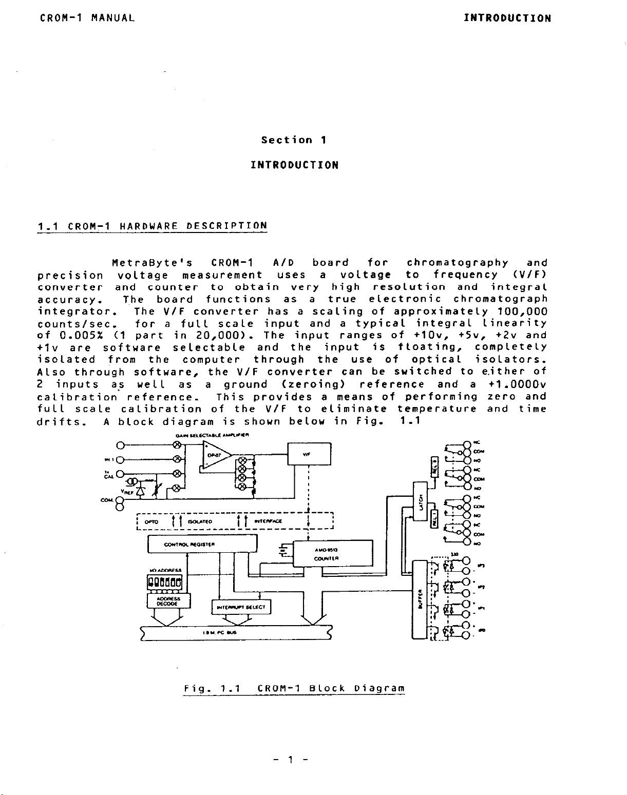
1.1 CROM-1 HARDWARE DESCRIPTION
A/D board
uses a voltage to frequency (V/F)
precision
MetraByte’s CRON-1
voltage
measurement
converter and counter to obtain very
accuracy.
The board functions as a true electronic chromatograph
for
high resolution and integral
chromatography
integrator. The V/F converter has a scaling of approximately 100,000
countslsec.
of 0.005% Cl part in 20,000).
tlv are
software selectable and the
for a full scale input and a typical integral linearity
The input ranges of +lOv, +5v, +2v and
input is
f Loating, completely
isolated from the computer through the use of optical isolators.
Also through software,
2 inputs as
well
calibration reference.
full
drifts.
scale
calibration of the V/F to eliminate temperature and time
A block diagram is shown below in Fig. 1.1
the V/F converter can be snitched to either of
as a ground (zeroing) reference and a +1 .oooov
This provides a means of performing zero and
0.I YLEcl.W wlrr”
cow 8 ‘I’ -I- 7 ’
c-~--i-i---o ____ Tie,.m.m.~+-~
L------ ___------------ ---
T
I ;
6
3
l--d-J
and
Fig. 1.1
CRON-1 Block Diagram
- 1 -
Page 6
INTRODUCTION
CRON-1 MANUAL
The CRON-1 includes a complex counter device,~ Advanced Micro Devices
AND-9513,
which contains five 16 bit counters.
Counters 1 and 2 are
cascaded to form a 32 bit counter that accumulates the pulses from
the V/F.
When running at lOOKHz,
a 32 bit counter will accumulate
pulses for almost 12 hours before overflowing. For increased counter
capacity,
.R 2 using software commands
normally unused.
Under softuare control i~t
oscillator source and decade scaler providing lNHz,
1KHz and 1OOHz frequencies.
it is also possible to cascade counters 3 & 4 to counters 1
only,
otherwise these counters
are
Counter 5 is used to generate periodic interrupts.
can be connected to a precision xtal
lOOKHz, IOKHz,
Any of these frequencies can be further
divided by any integer in the range 2 - 65,535 loaded into counter 5.
The output of counter 5 in turn can generate a hardware interrupt on
any of the PC expansion bus
interrupt levels 2 thru 7. The active
interrupt level (2-7) is selected by softuare. The interrupt service
routine can simultaneously
the count in process,
so that it is possible to store the counts at
equal intervals of time and so
interval
and
the
integrated
latch counters 1 & 2 without disturbing
measure the voltage during
volt-seconds between
=ny
pair of
the
intervals. This feature is useful for determining the area under the
peaks of the chromatogram to very high precision.
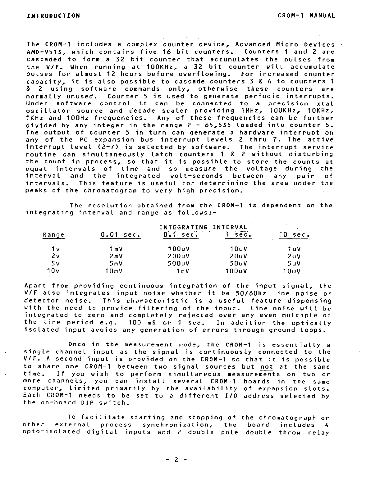
The resolution obtained from the CRON-1 is dependent on the
integrating interval and range as follous:-
INTEGRATING INTERVAL
Range
Iv
2v
5v
1ov
0.01 sec.
1mV
2mV
5mV
10mV
0.1 sec.
1 oouv
zoouv 2O"V
5OO"V
1mV
1 sec. 10 sec.
1O”V
1”V
2"V
5O"V
1 oouv
5"V
1O”V
Apart from providing continuous integration of the input signal, the
V/F also integrates input noise whether it be 50/60Hz line noise or
detector noise.
with the need to provide filtering of the input.
This characteristic is a useful feature dispensing
Line noise will be
integrated to zero and completely rejected over any even multiple of
the line period e.g.
100 mS or 1 sec. In addition the optically
isolated input avoids any generation of errors through ground loops.
Once in the measurement mode,
single channel input as the signal
V/F.
A second input
is provided on the CRON-1 so that it is possible
is continuously connected to the
the CROM-1 is essentially a
to share one CROM-1 between two signal sources but not at the same
time.
more
computer,
If you wish to perform
channels,
you can install severa 1
limited primarily by the availability of expansion slots.
simultaneous measurements on
CROM-1 boards in the same
two or
Each CROM-1 needs to be set to a different I/O address selected by
the on-board DIP switch.
To facilitate starting and stopping of the chromatograph or
other
external
opto-isolated digital
process synchronization,
inputs and 2 double pole double
- 2 -
the board
includes 4
throw
relay
Page 7
CRON-1 MANUAL
INTRODUCTION
outputs.
120~ A.C.(resistive).
ports.All the digital
isolated
the
lOOKHz/F.S. -
linearity).
V/F at
Lou-level)
contact NetraByte.
can be
measurement applications e.g. direct interface
etc., our
information and assistance.
installation in computers with reduced length expansion
the Tandy
machines.
1.2 CROM-1 SOFTWARE DESCRIPTION
The output contacts are rated at 1A at 28v D.C. or 0.5A at
These
I/O
from the computer to improve safety and noise performance.
By changing component values, it
any
rate
from lOKHz/F.S. to
higher
It
is
also
and bipolar (+/-I inputs.
Apart from its uses in chromatography, the CRON-1
used in many other precision
applications engineering staff
The CROM-1 is a 9 inch “3/4
possible to provide other ranges (including
1000 as well as
I/O
lines are addressed through separate
connections to the board are
is
also
lMHz/F.S (standard is
frequencies tend to degrade integral
For these modifications, please
and
will be glad to provide
slot”
standard IBM PC/XT/AT
slow
board
electrically
possible to run
high
to a thermocouple
and
precision
suitable for
slots
such as
compatible
The CRON-1
software.
MetraByte’s standard utility’ package vhich is directed towards the
needs of users
includes a BASIC
commented assembly language source listing for the driver (CROM.ASN),
a programming example EX.BAS and a simple menu driven logging program
CCROM.BAS 8 CRON.EXE).
provided to
Compiler or Microsoft Quick Basic.
this manual.
offers two optional menu driven
for the CROM-1 by Laboratory Technologies Corporation. The first and
more expensive option is the general purpose Labtech Notebook that
may be supplemented with Labtech Chrom
and the second is Labtech CHRON+ which is specifically designed for
chromatography analysis
capabilities of Labtech Notebook,
demonstration disk.
our
catalog,
LABTECH NOTEBOOK
Included in the price
who
callable
allow
For the user who wishes to avoid programming,
a brief guide follous:-
can be used with several different types of
and supplied with
wish to
In addition, the object file CCROH.OBJj is
the use of compiled BASICA such as the IBM Basic
only.
perform
machine language driver CRON.BIN, a fully
data acquisition packages developed
If
call
The features of these products are detailed in
This is a general purpose data
control package that may be used with many other
MetraByte boards as
menus, it
allows
their own programming.
This software is documented in
for chromatography analysis,
YO”
or mail NetraByte for a free
are interested in the
well
you to
as CRON-1. Through user
control triggering,
the board is
This
NetraByte
acquisition and
-3-
Page 8
INTRODUCTION
CROM-1 MANUAL
LABTECH CHROM
LARTECH CHROMt
sampling, graphing,
filing and analysis of data.
Analysis is through built in functions including
curve fitting and fast Fourier
also allows acquisition of
data
another program and links to
transforms. It
while running
Lotus l-2-3 for
additional analysis and graphing.
This is an automatic analysis package that is
used together with Labtech Notebook. It performs
an automatic analysis of the chromatogram peaks,
reporting area,
displaying, printing or
retention time and height,
storing this data to
disk.
This is a Lower cost package for
only. It performs
Notebook and Labtech
does not include
the
the general
functions of Labtech
Chrom
for
chromatography
the CROM-1 but
data acquisition
and analysis capabilities of Labtech Notebook.
- G -
Page 9
CROM-1 MANUAL
2.1 BACKING UP THE DISK
INSTALLATION
Section 2
INSTALLATION
The software supplied with CROW-l is
in DOS 1.10 double
sided (320K) format which can be read by DOS versions 1.1, 2.0, 2.1,
3.0 and 3.1. It is advisable to make a back up copy before using the
softuare,
although if for any reason you lose the softuare, MetraByte
uill always provide a free replacement. The easiest uay to copy the
original to any other disk formatted under any other revision of DOS
is to insert the disk in your A drive and from DOS enter:-
COPY A:*.* 8: (or other destination drive specifier)
2.2 HARDWARE INSTALLATION
The CROM-1 board uses 4 consecutive address locations in
I/O space. Some I/O address locations will already be occupied by
internal I/O and other peripheral cards,
so to provide flexibility in
avoiding conflict with these devices the base I/O address can be set
by the Base Address D.I.P. switch to be on a 4 bit boundary anywhere
in
the I.B.M. P.C. decoded I/O space.
This I/O address space
extends. from decimal 512-1023 (Hex 200-3FF) which is many times
larger than is ever likely to be fully occupied.
usual
I/O address assignments
from data in the “IBM Technical
Summarising the
Reference Manual”:-
ADDRESS(Hex)
000-l FF
1 FO-1 F8
ZOO-2OF
210-217
220-24F
278-27F
ZFO-2F7
ZFB-2FF
300-31 F
320-32F
DEVICE
ADDRESSfHex)
Internal system 378-37F
Hard disk (PC/AT)
Game
Expansion unit
380-38C
380-389
3AO-3A9
Reserved 3EO-3BF
Reserved
LPTZ:
3CO-3CF
3DO-3DF
COMZ: 3EO-3E7
Prototype card 3 FO-3 F7
Hard disk (PC/XT)
3F8-3FF
DEVICE
LPTl :
SOLE corn”.
Binary comm. 2
Binary comm. 1
Mono dsp/LPTl :
Reserved
Color graphics
Reserved
Floppy disk
con1 :
Page 10
INSTALLATION
This covers thee standard I/O.options, but if youhave other
I/O peripherals e.g.
boards,
space.
not be concerned with a possible conflict with any add-on memory. If
multiple CROM-1 boards
one must be set to a different base I/O address.
I/O address of Hex 300.
not need to be altered.
before you install the board in your computer,
disk in your floppy drive and enter:-
This runs a self-explanatory program (INSTALL.EXEj that will give you
a pictorial view of the base address switch setting on the CROM-1.
After entering your choice of address,
you see it on the screen and press <ESC> to exit back to DOS.
will also
conflict
installed.
computer,
for IBM standard devices (although the same mapping is followed by
most compatibles) and may not be totally foolproof as far as.non-IBM
peripherals are concerned.
correctly, or
computer e.g.
normal,
have set the base I/O address,
need to provide it
programs.
prototype cards etc.
Memory addressing is separate from I/O addressing so you need
The CROM:l is shipped withy its DIP switch set for a base
A> INSTALL
See
uith
it can safely be ignored.
remove the CROFT-1 and try a different I/O address.
warning
standard
If you receive a warning for a device that is not in your
interferes in some
disk drives etc. or your computer fails to boot up as
in the initializing or configuration sections of
battery backed up clocks, special graphics
they
are installed in the same computer, then each
This is usually a good default value, and may
If you want to check or change the setting
messages of
IBM peripheral
If your CROM-1 does not appear to work
make a note of its value as you vi11
will
way
also be sharing I/O address
insert the software
simply set the switch the way
settings which could possibly
devices if you have them
These cautions apply strictly
uith other devices on your
CROFT-1 MANUAL
YOU
Once you
install
To
removing the board from its protective
is a good precaution
have accumulated by touching the
before
computer and remove the case (See IBM “Guide to Operations” for your
model of computer if you are not already expert at this maneuver).
Remove a vacant back plate by undoing the scre” at the top and plug
the CROM-1 in and then
The CROM-1 will fit in any of the regular full depth slots of the IBM
PC/XT/AT or ‘three-quarter”
removing any peripheral board. Failing to observe this precaution
can cause costly damage to the electronics of your computer and/or
the CROM-1
board,
electrostatically
shipping.
YO” Plug
Remember, always TURN OFF THE POWER whenever installing or
board.
MetraByte recommends that
the board
the CROM-1
to discharge any electrostatic charge you may
into it. TURN OFF THE POWER on your
replace the screw and secure the backplate.
slots
If for any reason you later remove the CROM-1
shielded
packaging and use it for
inside
metal frame of your computer just
such as those in the Tandy 1000.
- 6 -
your
electrostatic packaging. It
YO”
computer,
retain the special
start by
storage
and
Page 11
CROM-1 MANUAL
Section 3
CROW1 HARDYARE
3.1 I/O ADDRESS MAP & REGISTER DATA FORMAT
REGISTER STRUCTURE
The information
in this section
needs of programmers and uith the exception
skipped if
you are using menu driven software such as Labtech or
is directed towards the
of Section 3.2 may be
CHROM+.
The chromatography board uses 4 consecutive I/O addresses.
The base I/O address is fully settable by means of a D.I.P.
the board (this is the only user settable component -
on
sui tch
see
Installation). If required more than one chromatography board can be
used in a
single computer provided that
operating interrupt levels are different.
their I/O addresses and
The I/O address map is as
follows:-
I/O ADDRESS
Read
FUNCTION
Write
Base address + 0 Counter data Counter data
+ 1
+ 2
+ 3
Counter status
Main control Main control
AUX. inputs
Counter control
Relay outputs
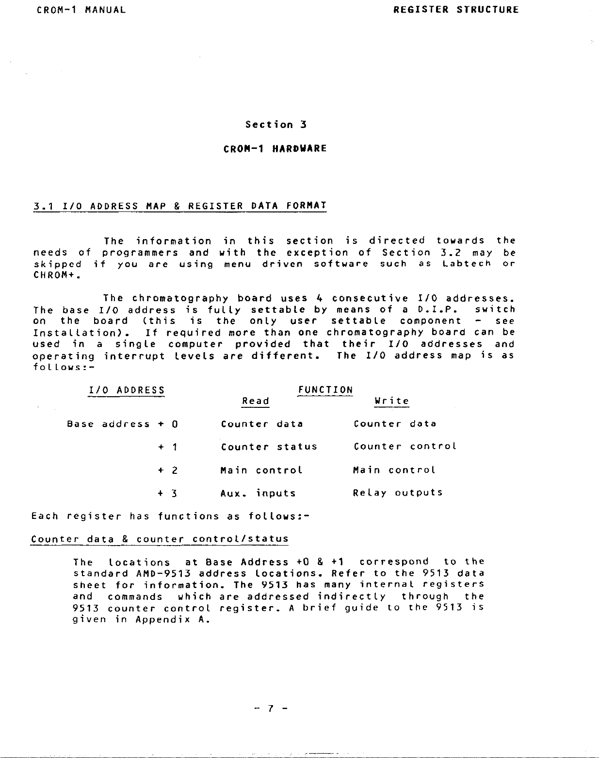
Each register has functions as follows:-
Counter data & counter control/status
The
locations
at Base Address +O & +1
standard AMD-9513 address locations. Refer to the 9513 data
sheet for information.
and
commands
which are addressed indirectly through
The 9513 has many internal registers
9513 counter control register.
given in Appendix A.
correspond to the
the
A brief guide to the 9513 is
- 7 -
Page 12
REGISTER STRUCTURE
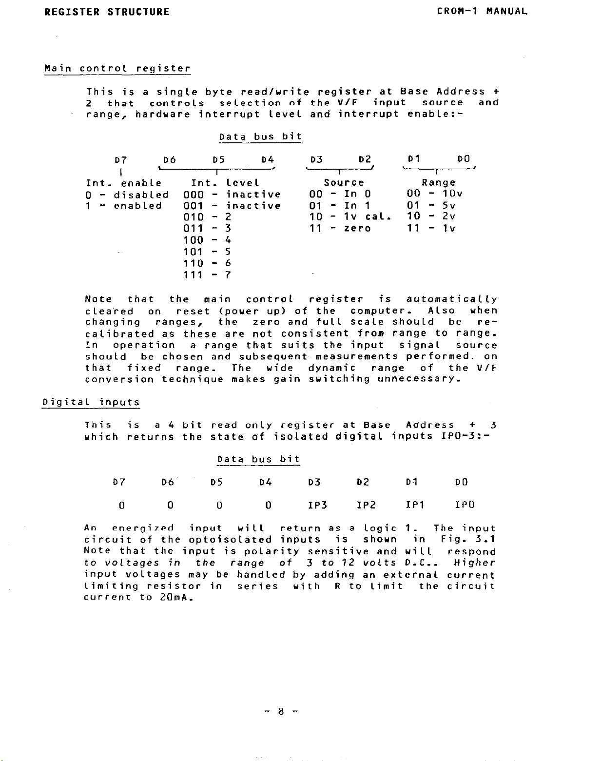
Main control register
This is a single byte read/write register at Base Address +
2 that
range, hardware interrupt level and interrupt enable:-
controls
selection of the V/F
Data bus bit
input
CROM-1 MANUAL
source and
D7
Int. enable
0 - disabled
1 - enabled 001 - inactive 01 - In 1
Note that
c lea’red on reset (pouer up) of the
changing ranges, the zero and full scale should be recalibrated as these are not consistent from range to range.
In operation
should
that
conversion technique makes gain switching unnecessary.
Di’gital inputs
This is
which returns the state of isolated digital inputs IPO-3:-
06 D5
I
I
Int. level
000 - inactive
010 - 2
011 -
100 - 4
101 - 5
110 - 6
111 - 7
the
a range th,at suits the input
be chosen and subsequent measurements performed. on
fixed range. The wide dynamic range of the V/F
a 4 bit read only register at Base
3
main
04
control
v G
Source Range
00 - In 0
10
-
Iv
cat.
11 - zero 11 - Iv
register is automatically
computer. Also
00 - 1ov
01 - 5v
10
- 2v
signal source
Address + 3
when
Data bus bit
07 06’ 05 04 03 02
0 0 0 0 IP3
An
energized input
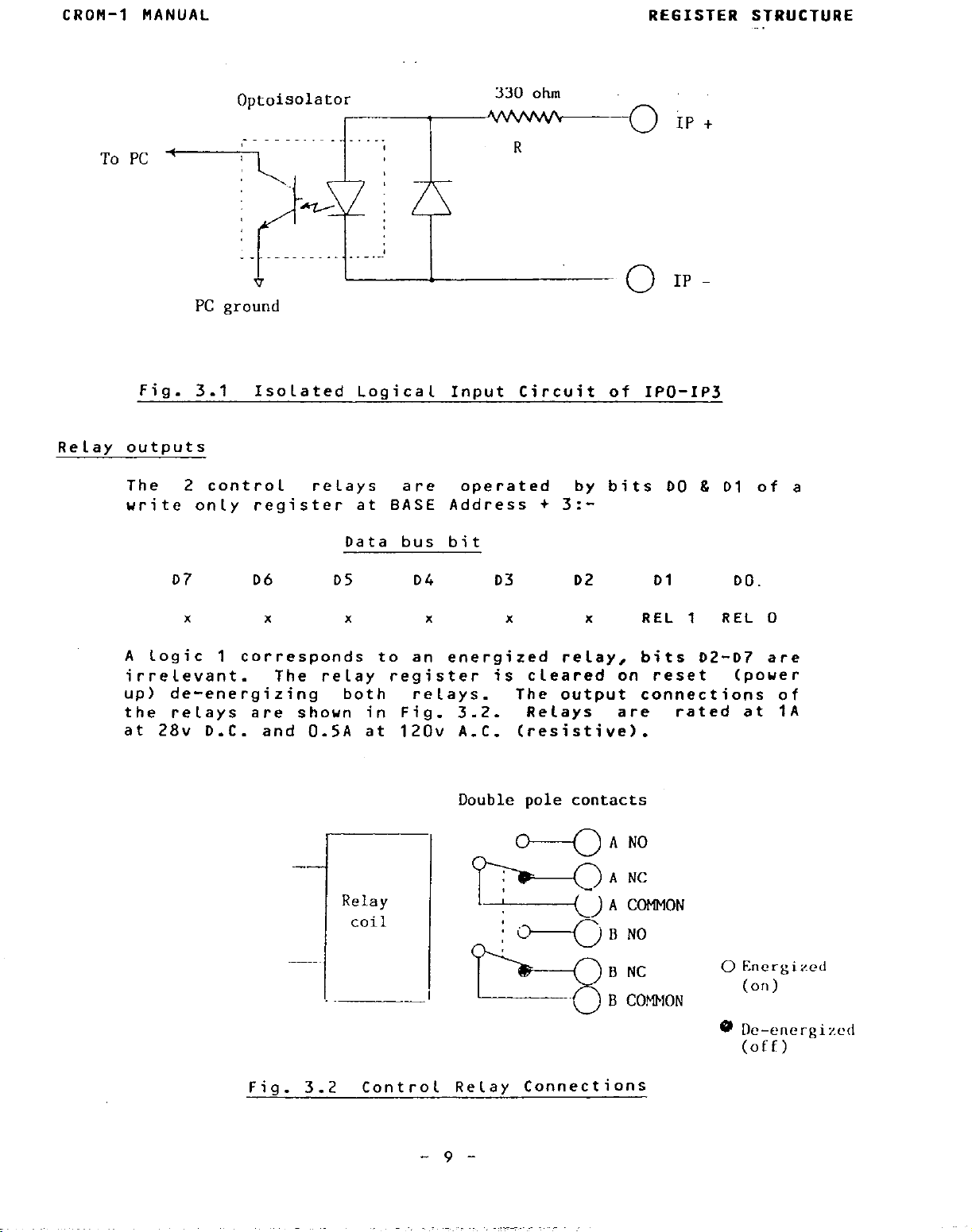
circuit of the optoisolated inputs is
Note that the input is polarity sensitive and will
to voltages in
input voltages may be handled by adding an external current
limiting resistor in
current to 2OmA.
the range of
ui
11
return as a logic 1. The input
series with
3 to 12 volts 0-C.. Higher
IP2 IPl
shown in Fig. 3.1
R to limit the circuit
01 DO
IPO
respond
- a -
Page 13
CROM-1 MANUAL
REGISTER STRUCTURE
Fig. 3.1
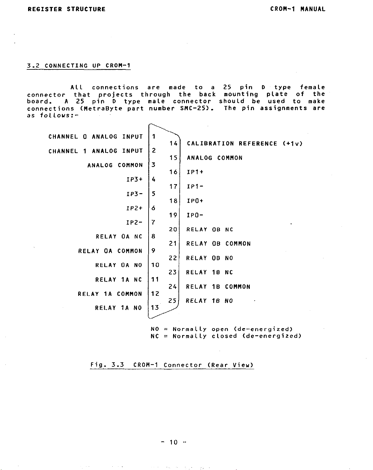
Relay outputs
The 2 control relays
write only register at BASE Address + 3:-
A Logic 1 corresponds to an energized relay, bits D2-07 are
irrelevant. The relay register is cleared on reset
up) de-energizing
the relays are shown in Fig. 3.2.
at 28~ D.C.
Isolated Logical Input Circuit of IPO-1~3
are
Data bus bit
07
x x x x x
D6 DS D4 03
both
and 0.5A at 120~ A.C. (resistive).
relays.
operated
Double
by bits DO & Dl of a
D2 01
x
The output connections of
Relays are
pole
contacts
REL 1
rated at 1A
A NO
DO
REL 0
(power
F
ig. 3.2
-
Control Relay Connect
- 9 -
A NC
A CCHTION
0 Energized
(or))
8 De-energized
(off)
ions
Page 14
REGISTER STRUCTURE
3.2 CONNECTING UP CROM-I
CROH-I MANUAL
All
connector that
board. A 25 pin D type male
connections CMetraByte part number SMC-25).
as follows:-
CHANNEL 0 ANALOG INPUT
CHANNEL I ANALOG INPUT
connections are
projects through
ANALOG COMMON
IP3f
IP3xp2+
IP2-
RELAY OA NC
RELAY OA COMMON
RELAY OA NO
RELAY IA NC
RELAY IA COMMON
RELAY IA NO
made to a 25 pin D
the back mounting plate of
connector should be used to make
\
14
i
CALIBRATION REFERENCE (+lv)
2
i
ANALOG COMMON
15
3
l( i
IPI+
4
IPI-
17
5
IPot
It 1
6
7
8
9
IO
11
12
I3
,
IPO-
15
I
2c
RELAY OB NC
21
RELAY OB COMMON
22
RELAY OB NO
23
RELAY IB NC
24
RELAY IB COMMON
RELAY IB NO
25
type
The pin assignments are
female
the
Fig. 3.3
NO = Normally open (de-energized)
NC = Normally closed (de-energized)
CROM-I Connector (Rear View)
- IO -
Page 15
CROM-I MANUAL
REGISTER STRUCTURE
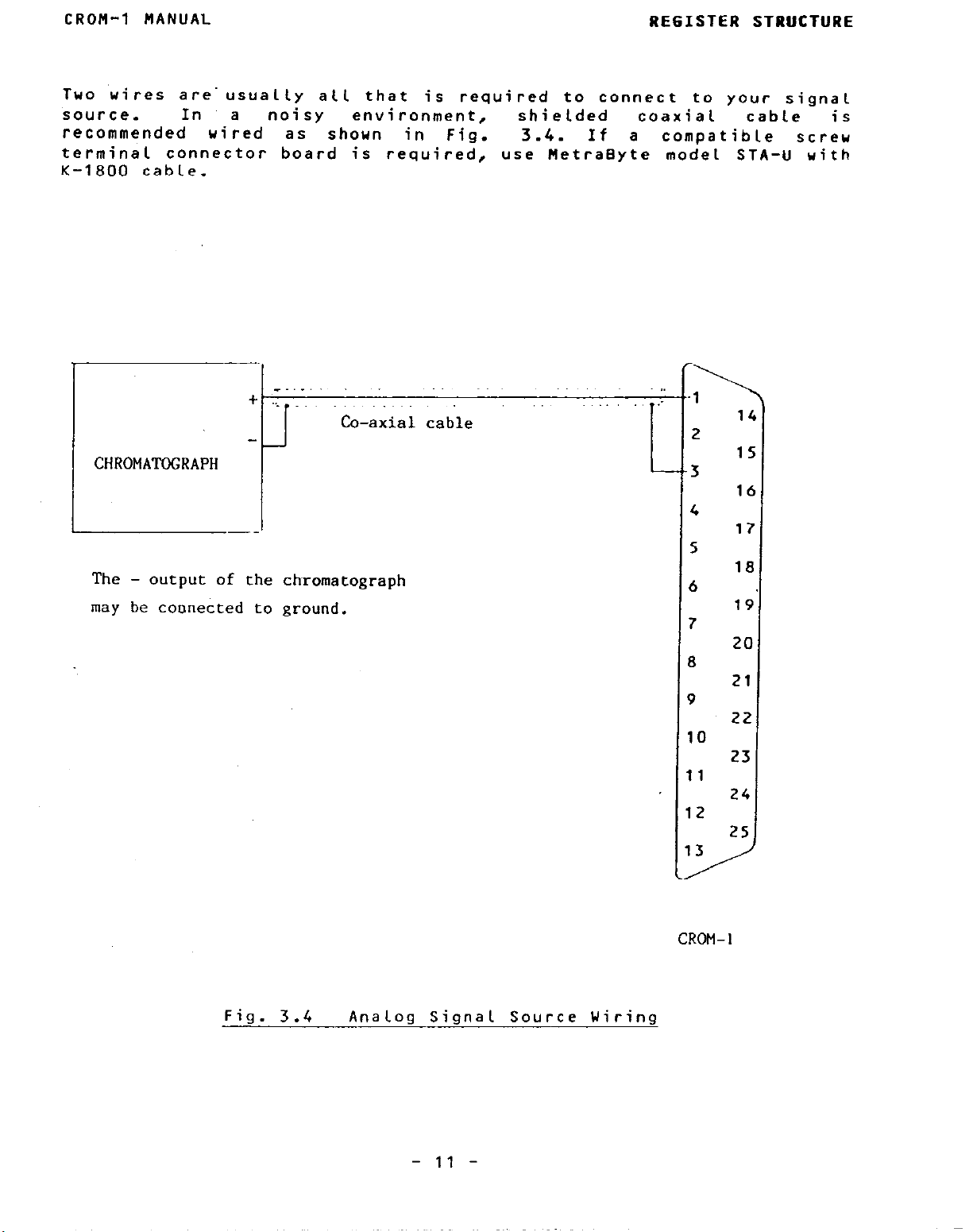
Two wires
source.
recommended uired as
terminal connector board is required,
K-1800 cable.
are.
usually all that is required to connect to your signal
In a noisy
environment,
shoun
in Fig. 3.4.
Co-axial cable
CHROMA’UXRAPH
The
- output
may be connected to ground.
of
the ch~romatograph
shielded
If a compatible screw
use MetraByte model STA-U with
coaxial
:
L
r
1
2
3
4
5
,
5
r
3
t
P
$
IO
1
1
I
2
1
3
1
cable is
14
I5
I6
17
I8
19’
20
21
22
23
24
25
Fig. 3.4 Analog Signal Source Wiring
- I1 -
CRC+-1
Page 16

PROGRAMMING
4.1 PROGRAMMING CROM-I
CROM-I MANUAL
Section 4
PROGRAMMING
This section provides
to use the MetraByte utility software supplied with CROM-1.
intend
package such as Labtech Notebook or CHROM+,
and refer to the instructions included in the Labtech documentation
instead.
and output’ instructions
functions or assembly language IN AL,DX and OUT DX;AL.
languages
instructions. For Microsoft Fortran,
that includes both
data
demanding, this can require many
understanding
CROM-I.
writing of interrupt
interrupts are
CROM-I_ To simplify program generation in
driver
package.
driver also includes a 10,000 point FIFO (first in - first out)
buffer to hold data uhich may then be accessed asynchronously by a
BASIC program using a single
process data in the program e.g. graph, f i le,
any
Each time the CALL is entered, one data item is removed from the
buffer for processing by the program.
CALL, the driver also looks after initialization of the CROM-I (this
is described in more detail in Section 4.5).
to operate
and
routine
speed
At the
(with
Programming directly with I/O commands involves formatting
dealing
of the devices,
Also many languages, such as BASIC, do not support the
Apart from providing an interrupt service routine, the
without affecting the sampling operation of the CROM-1.
with a high
lowest level,
such as
the
I/O
with
very
“CROM.BIN” is included in the CROH-1 software
exception of
and memory access routines.
absolute I/O
routines, and
effectively utilised in the operation of
information to programmers uho wish
If you
level
CROM-I is programmed using I/O input
BASIC’s INP
lines of code and necessitates an
data format
line CALL statement. This lets you
menu driven data acquisition
you can skip this section
(port)
Fortran)
MetraByte can supply a’ library
add’resses.
and architecture of
this is a major
BASIC,.
analyze or print it at
On the first entry to the
and OUT port,Y
Most other
have equivalent
Although
obstacle as
a special
not
the
the
I/O
The object file of the driver, CROM.OBJ is included for
linking when
Compiler
assembly language programmers and those wishing to interface to other
or
compiling your
Microsoft Quick Basic
r .,,I
BASICA program using the IBM Uasic
- 12 -
(see Section
4.10).
Also
for
Page 17

CROM-1 MANUAL
PR06RAMlN6
languages,
is provided (see Section 4.12).
as required,
operation of the driver in its unmodified form.
4.2 LOADING THE MACHINE LANGUAGE CALL ROUTINE “CROM.BIN”
must first be loaded into memory.
part of memory that is being used by the main body of your program or
DOS or programs which use high memory such as “RAU disks”.
collide uith another program,
although sometimes the results can be more peculiar.
need to turn the power off and restore it to re-boot the machine, the
usual Ctrl-Alt-Delete reset may fail to do anything.
ominous,
FIFO buffer),
l.oading sequence is as follous:-
the fully commented source code, CROM.ASM, of the driver
This can’ be modi~fied and re-assembled
though MetraBytecan only support
In
order to make use of the CALL routine “CROM.BIN”, it
You must avoid loading it over any
your computer will usually hang up
but apart from the frustration,
Since CROM.BIN uses about 41 Kbytes of memory
it is best loaded outside BASIC’s workspace.
no damage will ever result!
inquiries concerning
If you do
Often you will
This may sound
(4OK is
A typical
the
xx100 DEF SEG = &H3000 ‘segment of memory to load link
(choose an empty area e.g. .g 192K)
xx110 BLOAD “CROM.BIN” 0
. _
Continue program
The above
BASIC program.
as EX.BAS.
specifies the load location for the CROM.BIN driver.
CALL’s will occur
DEF SEG’s in your program,
with the same DEF SEG = SH3000 that you used to Load the link (see
CALL and DEF SEG in your BASIC reference manual).
Load CROM.BIN is seldom much of a problem now that most PC’s are
equipped with at least 256K of memory.
provides some insight into the process of choosing a memory location
for the driver and what to do if memory is in short
required being dependent on the version
revision adds extra features!).
overleaf shows
initializing steps will be the same for any interpreted
A more comprehensive example is provided on the disk
Note that the DEF SEG = RH3000 statement in Line 100
to
the
DOS occupies the bottom of memory, the amount of memory
what happens after booting up BASICA.
last
,
remember to precede your CALL’s to CROU-1
‘load driver
All subsequent
DEF SEG address, so if you add other
Finding a place to
The following explanation
supply.
(it grows as each new
The simplified memory map in Fig 4.1
- 13 -
Page 18

PROGRAMING
CROM-1 MANUAL
Bottom . . OK
I9K
98K
DOS 1.1
_-
------DOS
_------
BASIC
______-
Free
memory
OK
126K
DOS 2.1
--
-------
BASIC
-------
Free
memory
OK
140K
DOS 3-O
~-
-------
DOS
BASIC
-------
Free
memory
Fig. 4.1 Memory map with DOS and BASIC installed
CROM.BIN should be loaded somewhere in the free memory area so that
it does not interfere with either BASIC or DOS.
98K CSHI880) for DOS 1.1,
for DOS 3.0. If you
126K CSHIF80) for DOS 2.1 or 140K CEH2300)
have 256K (EH4000) or more of memory, then
This would be above
loading the link at DEF SEG = EH2800 or &H3000 is a good solution for
all versions of DOS.
Dne further small detail is that if you are
using a PC compatible which does not have BASIC in ROM like the IBM,
then BASIC is usually loaded as an
.EXE file from the top of memory
down _ This is likely to fill up to 64K of the top segment of
memory. Some virtual disks or print spoolers will do the same.
if you are
Borland’s Sidekick etc.
accustomed to
be aware that these will push the loading
using
DOS resident programs such as
Also
floor of BASIC up and require a compensating increase in the location
of CROM.BIN.
If you are memory
limited,
or you have so
much resident
stuff that there is no Longer 64~ left for BASIC to Load in, then
BASIC will attempt to make the most of what it can find.
Instead of
getting the message when BASIC has toaded:-
The IBM Personal Computer Basic
Version AZ.0 Copyright IBM Corp. 1981, 1982, 1983
60865 Bytes free
Ok
- 14 -
Page 19

CROM-I MANUAL
PROGRAIMING
Your may only get 49345 bytes free
bytes) for example.
found. You can then contract this space further using the CLEAR
function and load the link at the end of BASIC. This is more
complicated,
CROM.BIN will use 41K bytes,
uorkspace (11K) but it may in some cases get us by.
code would now be:-
xx100 CLEAR, 11000 ‘contracts BASIC workspace
add 11000 to it
workspace.
load segment :-
XXI10
xx120
xx130
xx140
xx150
Proceed with your program as before
but just as effective.
Let’s suppose ue
Next ue need to find out where BASIC has loaded in memory,
Memory locations &HSIO and &HSII aluays contain
DEF SEG = 0
LS = 256*PEEK(EH511)+PEEK(&H510)
SG = LS + llOOOf16 ‘remember segment addresses are on
DEF SEG = SG
BLOAD “CROM.BIN”,O
. .
In this case make a note of what space BASIC has
get
which does not leave much for BASIC’s
and load CROM.BIN just after the end of BASIC
(or something less than 60000
the message
52000
Our initializing
bytes free.
BASIC’s
‘set up to read &HSIO and RHSII
’ load segment
I6 byte (paragraph) boundaries
‘set up to load link
‘load link
As CROM.BIN is a large file,
workspace are minimal.
more memory to your computer,
the FIFO buffer by re-assembling CROM.ASM.
4.3 STRUCTURE OF THE CALL STATEMENT
If you are new to using CALL statements, this explanation
may assist you in understanding how the CALL transfers execution to
the machine language (binary) driver routine (also see CALL in your
Basic Reference Manual).
SG statement sets the segment address at which the CALL subroutine is
located. The CALL statement for the CROM.BIN driver must be of the
form:-
XXXXX
Let us examine the parameters after CALL one by one:-
CROM - In interpreted BASIC this is a variable
CALL CROM CA, BUFX, CTRLXCO), FLAG%)
the offset of the start of our routine from the segment
defined in the last DEF SEG statement. In our case
Generally the simplest recourse is to add
Prior to entering the CALL, the DEF SEG =
the advantages of contracting BASIC’s
an alternative is to reduce the size of
that specifies
its
- 15 -
Page 20

PROCRAIHING
CROM-1 MANUAL
value is always set to zero CCROM = 0).
In compiled BASIC (and most other compiled Languages)
CROM has a different significance - it is the
the external routine that the linker will look for.
name of
A
BUFX -
4
CTRLXC7) -
This is a single precision (4 byte)
passes one item of count data from the FIFO buffer.
This is an integer variable that returns
valid data items in
buffer is empty (variable A
This is a 6 element integer array that specifies
operating conditions of the CROM-1 as follous:-
CTRLXCO) -
CTRLXCl) -
CTRLXC2) - selects interrupt rate in mS
selects
selects
0 = 1ov
3 = Iv
e.g. CTRLXCZ) = 1000
generates an interrupt every second
the buffer.
input channel
0 = CHO
1 = CHl
2 = Calibrate
3 = Zero
full
1 = 5v
2 = 2v
will
scale
real
When BUFX = 0, the
also return zero).
range
variable, that
the number of
the
CTRLXC3) - Specifies numbers of samples required
CTRLXC41 - selects interrupt
If CTRLXC3) <> 2 thru 7= 0, interrupts
will be disabled.
CTRLXC5) -
CTRLXC6) - returns interrupt status
FLAG% -
parameters.
(pointers) are passed in the sequence written ,to BASIC’s stack. The
CALL routine unloads these pointers from the stack and uses them to
locate the variables in BASIC’s data space so data can be exchanged
with them.
Returns error code if any of the specifying CTRLXC*)
are out of range (see Section 4.7)
The four variables within brackets are known as the CALL
On executing the CALL,
Three important format requirements must be met:-
specifies Base
DIP suitch) e.g.
1 = interrupts active
0 = interrupts disabled
the addresses of the variables
level, value 2-7.
I/O
address. (as set on
CTRLX(4) = &H300
- 16 -
Page 21

PRO6RAHMIN6
1. -
The CALL parameters are positional. The subroutine knows
nothing of
the names of the variables,
just
their
locations from the order of their pointers on the stack.
If you urite:-
xxxxx CALL CROM (BUFX, A, CTRLXCO), FLAG%)
YOU
ui 11 mix up
the CALL
interpret BUFX as the
routine,
count data,
since it
will
and A as the buffer
data etc. Also the variables will now be the wrong types
which is
more serious. The
parameters must
aluays be
uritten in the correct order:-
(count data, buffer, control data, errors)
2. -
The CALL routine expects its parameters to be of correct
type and uill write and read to
the
variables on this
assumption:-
(real,
If you slip up and use the wrong variable
CALL parameters,
integer, integer array, integer)
types
the routine will not function correctly
in the
and may hang up the program.
3. -
Apart from these
want,
Strictly,
You cannot
parameter 1
perform any arithmetic functions within the
ist brackets of the CALL statement. There can
only be a 1 ist of variables.
replace var
iables by constants.
restrictions, you can name the variables what you
the names
YOU
should declare
the examples are just
in
Also you are not allowed to
convenient
mnemonics.
the variables before executing
the
CALL. If you do not, the simple variables will be declared by
default on
execution, but array variable
obviously cannot be
dimensioned by default and must be dimensioned before the CALL to
pass data correctly if used as a CALL parameter.
In the case of the
integer array, the first element CTRLXCO) should be specified as the
data variable
so that the CALL routine can locate all other data
items in the array correctly.
4.4 INTERRUPTS
Variable CTRL%CL) specifies the harduare interrupt
that CROM-1 will use on the expansion bus
The
PC’S
8259
interrupt controller can
to generate interrupts.
prioritize 8
different
hardware interrupts. Level 0 is the highest priority and is used by
the internal
timer which generates an interrupt about 18 times/set.
This is used by the BIOS and DOS to provide the system time and
date.
Level 1 is used by the keyboard to signal that a key has been
- 17 -
level
Page 22

PROGRAMMING CROM-1 MANUAL
pressed and invoke a keyboard handling routine.
are internal to the PC and not available on the expansion bus.
of the remaining
interrupt
follows:-
On standard PC and PC/XT models any of levels 2 thru 5 are good
choices if the corresponding peripheral device i’s not installed e.g.
if you have no second serial port, you can use Level 3. The PC/AT has
‘an expanded interrupt
second 8259 interrupt
however these are only available on the 16 bit portion of the PC/AT
expansion bus
PC/AT’s, this narrows down the choice to Levels 3 thru 5.
lower Levels.
are enabled, an interrupt
microseconds of its generation.
with one from the CROM-I, it can delay servicing of the CROM-1
interrupt. The main culprit here is the timer interrupt on level 0,
it can occasionally delay the CROM-1 interrupt by 30-40 microseconds,
enough to
The next interval will be shorter by an equal amount, so that over a
long period it has no effect, but from interval to interval the
latency or variation in
introduce some small variation in the latching interval. This is not
usually a significant problem, and for ultimate precision the jitter
can be
through
keyboard or COM:
unnecessary as the error introduced amounts to 0.003% or Less.
levels
Level 2: Reserved (used for cascade input on
Level 3:
Level 4: Used by COMl:
Level 5:
Level 6:
Level 7:
connectors
The higher level interrupts will get serviced ahead of the
If no higher Level interrupt is pending and interrupts
increase the count by 2 or 3 count/sec.s at full scale.
practically eliminated by
the
8259 mask
Levels
are assigned to
Used by COM2:
Used by LPT2:
Used by floppy disk drive adapter
Used by LPTl:
structure and level 2 is used to
controller to provide an additional 8 Levels,
ports uhile
2 thru 7 are usually
the
serial port if instal
serial port if instal
or hard disk if insta
and are not avai table to
will normally be serviced within a feu
If a higher level interrupt collides
delay in
register,
gathering
servicing
disabling the timer
and refraining from
standard
data.
Both levels 0 and 1
A few
avai table. The
peripherals as
PC/AT only)
led
led
lled
cascade a
For
the
the
CROM-1.
interrupt can
interrupt
using
Usually
this is
Counter 5 on the CROM-1 is initialized with a 1KHz clock
input
generates a precise periodic interrupt
control register is set.
latches counters 1 & 2, changes the 32 bit integer data to a 4 byte
single precision floating point real and places the data on the top
of the FIFO buffer. This continues until interrupts are disabled by
one of the 3 following conditions:-
or:-
and
divides by
The number of samples specified in CTRLXC3) is
1.
reached.
2. The buffer fills to capacity (9,999 data items).
the
integer
The interrupt service routine in the driver
specified in
when bit 7 of the CROM-1
CTRLXCZ) _ This
- ia -
Page 23

CROM-1 MANUAL
PROGRAMING
or:-
CTRLXC6) provides
long as interrupts are active, CTRLXf6) is set to 1. As soon as any
of the above termination conditions are met, it is
indicate that interrupts have been
interrupt is disabled and further data sampling has ceased, you may
cant inue unloading the FIFO buffer by accessing
action is demonstrated in EX.BAS.
4.5 INITIALIZATION
but the CROM-1 is initialized. Initialiazing performs the following
operations:-
3. You abort operation by entering the CALL with
CTRLXC4) = 0.
information on the status of the interrupts. As
set
disabled.
The first time the CALL is executed,
1. Sets the master mode register of the AMD9513A counter
Sets counter 1, 2 and 5 mode registers
2.
3. Zeroes (resets) counters 1 & 2
4. Loads counter 5 for specified interrupt rate
Installs interrupt handler
5.
6. Enables interrupt (if CTRLX(4) = 0, disables interrupt)
Even though
the CALL. This
no data is returned,
to 0 to
the
Subsequent
CTRLXtO thru S), unchanged
variable A.
altered, the driver
subsequent CALL and also clear the buffer.
4.6 FIFO BUFFER OPER~ATION
The interrupt service routine performs the following operations:-
Entering the CALL takes the data
and returns the accumulated count in variable A. The bottom of buffer
entries. to the CALL with
will
If
however any of the parameters in CTRLXCO thru 5) are
will
In operation, counter 5 generates a periodic
1. Latches counters 1 & 2 “on the fly”. The counters are
latched at the same instant, this does not disturb the
count in process.
Reads the 32 bit integer from the latches, turns
2.
data into 4
format, and puts it on
incrementing the top of buffer pointer.
perform a re-initialization of CROM-1 on a
byte
return data from the FIFO buffer in
floating point single precision
item from the bottom of the buffer
the
top of
setup
the
parameters, i.e.
interrupt.
the
FIFO
buffer,
- 19 -
Page 24

PROGRAMING
CROM-1 MANUAL
pointer is incremented. BUFX returns
pointers and indicates the amount of data left in the buffer. The
buffer is circular and can contain up to 10,000 data items. If you
were sampling at 1 interrupt/second this would be sufficient to hold
nearly 3 hours of data,
the buffer is being continually unloaded and data processed, although
you may not be able to keep up with the rate at which data is being
acquired.
samples/set and unloading and processing data at 3 sampleslsec. the
buffer is effectively being filled at 7 samples/set.
nearly 24 minutes to overflow.
are disabled so that data in the buffer is conserved.
as much data es possible before suspension of operation, but it is
your
sample rate,
will also be zero)
simple routine method of sensing the presence of data and continuing
with your program is:-
responsibility to avoid this condition by correct choice of
xxx00 CALL CROM CA, BUFX, CTRLXfO), FLAG%)
xxx10 IF BUFX = 0 AND CTRLX(6) ~= 0 THEN END
xxx20 IF BUFX = 0 GOT0 xxx00 ‘wait for data to be added to FIFO
. _
. . (process data any way you want)
. .
yyyyy GOT0 xxx00 ‘get next data point
For example, if
If the buffer becomes completely filled, further interrupts
duration and simultaneous processing demands.
If the buffer is empty,
or 16 minutes at 10 samples/set. In practice
YOU
indicating that there is no available data.
are filling the buffer at 10
BUFX will be retuwed zero (and A
the difference between the
and will take
This salvages
‘all data read out
A
Note that the value in A is the cumulative count. To obtain the
change in
previous value of A must be subtracted from it.
accomplished by re-assembling CROM.ASM.
4 times the number of data items desired (4 bytes per item).
driver is designed to operate within a 64K segment, and the buffer
length cannot exceed 15,000 items without major modifications to the
driver.
4.7 ERROR CODES
in FLAG%.
sample
possible to start making readings if an error condition exists, so
you should check for errors after initializing.
count in a sampling
Changing
Some value checking is performed on entry data and returned
This stops you setting up the CALL with interrupt
rate -6 etc. or other incorrect
the capacity of
interval between interrupts,
the buffer
Change the LEN BUF equate to
parameters. It is
can
the
only
The
level 9,
not
be
- 20 -
Page 25

CROM-1 MANUAL
Error code # Problem
PROGRAMING
1 CTRLX (0) - channel data, <O or >3
2
3
4 CTRLX(4) - interrupt Level, (2 or >7
5 CTRLXCS)
Checking for errors is easily performed after a CALL:-
xxx00 CALL CROM (A, BUFX, CTRLXfO))
xxx10 IF CTRL%(5)<>0 THEN PRINT "Error number ";CTRL%(SI:STOP
4.8 ZEROING AND CALIBRATION
V/F converters exhibit zero and gain drift with time and
temperature. To minimise this problem, the CROM-1 can be i.nternally
connected to zero and Iv calibration references. The V/F is slightly
offset at its zero, so that instead of producing a zero count for
zero volts in,
‘2%
of
full scale).
the range selected, on a lv range uhere this corresponds
sea Le, about 90,000
it will return about 2000 - 3000 counts/set.
- 110,000 counts/set.
CTRLXfl) - range data, <O or >3
CTRLXCZ) - interrupt rate (4mS
(0 terminates interruptsif active)
- base address,
The count returned for Iv input will depend on
is typical.
c&H100 or >&H3FC
(about
to full
Performing a zero/calibration before starting to sample
data uill return the calibration constant in counts per volt per
second. This calibration step corrects for
dritts.
end of sampling and the start and end values averaged. The data must
then be post processed to correct it.
method is unnecessary and
durations. An example of a pre-measurement calibration routine is in
EX.BAS.
4.9 EXAMPLE BASIC PROGRAMS
first EX.BAS is a simple program to
CALL. It is
information.
Over a long measurement run,
only justified over
Two example BASICA programs are provided on the disk.
commented and
it shows
YOU
can be
how to
- 21 -
it can
Usually this more elaborate
illustrate the operation of the
listed to provide
load CROH.BIN,
also
all
very
gain and
be repeated at the
long sampling
further
initialize
zero
The
the
Page 26

PROGRAMING
CROM-1, auto-calibrate CROM-1 and then read out data for 6 seconds at
It
10 samples/set.
In practice,
this example is of short duration to demonstrate how things work you can easily alter it.
program
chromatograph uill require in the form of a menu driven program.
will optionally, generate
(suitable for Lotus l-2-3, use IMPORT/NUMBERS), and plot the data on
the screen as it is acquired.
compiled with Microsoft Quick Basic, this is CROM.EXE.
CROM.BAS, can be modified to requirements and used as an interpreted
program or re-compiled. This program and
fully described in Appendix A.
4.10 COMPILING A BASIC PROGRAM
that performs most of the
sampling would take place for a much
The second program CROM.BAS is a more complicated BASICA
also illustrates the action of the FIFO buffer.
an ASCII
A faster running version has been
tasks that
comma delimited .PRN data
its
interfacing to a
operation are
CROM-1 MANUAL
longer
duration,
The source,
It
file
more
After you have your program running in interpreted BASIC,
YOU may
Interpreted
statement, and a sizable program particularly with extensive analysis
or data
execute. One of the simplest ways
your
Compiler or Quick Basic Compiler.
improvement in speed by a factor of 3 to 30 times depending on the
type of operations in the program.
spend some time
capabilities of the Basic Compiler, try out a
used to some of the differences from interpreted BASIC e.g. you must
declare all arrays prior to use etc.
follous:-
program using the IBM
1.
2. Store your program in
3.
find that
BASIC requires
processing loops can take a good part of a second to
Before you charge into compiling your measurement program,
Take your interpreted BASIC program and delete all lines that
load CROM.BIN e.g.
Compile it CBASCOM yourprog) with whatever compiler switches
you require.
YOU
familiarizing
Fix any errors before proceeding.
need to
several mi 1 liseconds to execute
Basic Compiler,
the DEF SEG and BLOAD.
ASCII
increase its execution
to speed things up is to compile
or
Microsoft Basic
This will usually lead to an
yourself
When you are ready proceed as
form (SAVE ‘yourprog.ba.s”,A).
with
the operation
few examples and get
.
speed.
each
and
4.
Next run the linker (it is best to use the one supplied with
your compiler rather then DOS).
- 22 -
Page 27

CROFT-1 MANUAL
A> LINK yourprog.obj + CROM.OBJ
IBM Personal Computer Linker
Version 1.10 (C)Copyright IBR Corp. 1982
Run File CMYPROG.EXEl
List File CNULL.MAPl
Libraries
C.LIBl
At the end of the linking
executable file MYPROG.EXE.
If you receive an "Unresolved
linker,
the CROM.OBJ declaration uhen prompted for the files to link, or that
the calls do not read CALL CROM (you must use the name CROM in the
call).
4.11 MULTIPLE CROM-l's IN ONE SYSTEM
system? To avoid conflicts,
address and for simultaneous operation be connected to a different
interrupt
routine. To do
,different locations in memory:-
it is most likely that you have either omitted or misnamed
What 'if you wish to operate more than one CROM-1 in a
each CROM-1 must have a different base
level.
xxx10 SGI = &H3000
xxx20 SG2 = &H4000
xxx30 DEF SEG = SGl
xxx40 BLOAD "CROM.BIN",O
xxx50 DEF SEG = SG2
xxx60 BLOAD "CROM.BIN",O
Each board must also be assigned its own CALL
this start by loading the CROFT-BIN routine at
session,
External"
you uill have a
error message from the
DOS
Now the CALL appropriate to each board can be entered as required. Note that
each CALL is preceded by a DEF SEG appropriate to that boardr-
yyyl0 DEF SEG = SGl
yyy20 CALL CROM CA, BUFAX, CTRLAXCO))
yyy30 DEF SEG = SG2
yyy40 CALL CROM (B, BUFBX, CTRLBXCO)) 'etc.
- 23 -
Page 28

PROGRAIIING
4.12 ASSEMBLY LANGUAGE PROGRAMMING
CROR-I RANUAL
The source code, CROR.ASM,
on disk.
CROM.ASM) or
Wordstar.
This
It
If
program,
designed for the CALL procedure used with BASIC.
interrupt,
communicate only with the
making it easy to lift them out unchanged.
accomplished by altering the
languages
addresses on the stack (unlike
are described in HOWTO.DOC.
file, the method of using the linker; EXEZBIN, debug and the Basic
interpreter achieve
HOUTO.DOC and Ctrl-NumLock to read it or list on the printer with
,Ctrl-PrtSc.
you "ill need to modify the entry and exit modules which are
and
Interfacing to calls from C,
usually
The steps involved in creating a BASIC loadable .BIN driver
can be printed out
examined
is heavily commented and self explanatory.
you wish to link this with another
FIFO
buffer handling routines are self-contained and
and
altered
local variables
entry and exit routines as these
pass pointers
BASIC
Basic tacks a .header onto a BLOADable
this are
detailed in
for the driver is also supplied
(use the Ctrl-PrtSc
with
Pascal
consisting of
which passes offsets only).
any
defined in the source,
and Fortran can also be
this file. Use TYPE
text editor e.g.
assembly language
The initializing,
segment:offset
and
TYPE
- 24 -
Page 29

CROM-1 MANUAL CALIBRATION
Section 5
CALIBRATION
5.1 CALIBRATION
Since the CROM-1 is normally autocalibrated to eliminate
zero and gain drifts,
calibration.
(marked R14) that adjust the
calibrate this reference, connect a
calibration reference output (pin 14 of the rear connector) to analog
common (pin 3).
Afte,r calibrating the internal reference,
run to check operation.
On the top of the board is a single multi-turn trimpot
Simply adjust the trimpot for a reading of +l.OOOOv.
there is only
internal Iv calibration reference. To
one user adjustment
digital voltmeter from
EX.ElAS or CROR.EXE can be
for
the
5.2 USER REPLACEABLE PARTS
Some of the components that interface to the outside world
through the rear connector are socketed so that you can replace them
if damaged by overloads, static etc.
Fig. 5.1.
Digital
optoisolator marked Uil.
and read the input port at
+31.
Combinations of inputs on will produce the
energized inputs e-g.
is a fault and none of the inputs appear to work right, check that
the base address setting of the board is correct.
With the inputs the following readings should be obtained:-
Inputs
ALL off
IPO on
IPl on
IP2 on
IP3 on
input lines, IPO-IP3,
To test digital inputs, use DEBUG or Basic
Base Address + 3 e.g.
Reading
IPl and IP3 on will return 10 etc.
The board layout is shown in
pass
0
1
2
4
through a
PRINT INPCBASE
a
sum corresponding to the
If there
If so, or if one
quad
- 25 -
Page 30

CALIBRATION
CROR-1 RANUAL
or more of the inputs are blown,
ILQ-74 opto-isolator.
If any problems are encountered with the analog inputs, CHO
or
Semiconductor
AD650JN) or counter (Advanced Micro Devices AR9513APC) give problems
they can be replaced.
damaged by overload of the contacts.
board but can be replaced if carefully removed. The
tested by performing an OUT BASE+3,
call Customer Service at (617)-880-3000.
CHl,
YO”
The output relays (Fujitsu type FBR244D005/02CS) can be
If you prefer to have RetraByte service the board, simply
can
HI3-508A-5. Likewise if the
replace
replace Ull with a Siemens ILQ-2 or
solid
state multiplexer U8 (Harris
V/F (Ana log Devices
They are soldered into the
relays can
1 or 2 using Basic or Debug.
be
Fig. 5.1
CROM-1 Board Layout
- 26 -
Page 31

CHIJPI-1 I’lANlJAL SPECIFICATIONS
Section 6
SPECIFICATIONS
6.1 ELECTRICAL
+5v power consumption
-5v, +12v, -12~ power
Input ranges
Input impedance
Input bias current
Input channels:
Input
voltage range
Input overvoltage
Resolution
Minimum resolvable
signal input
common mode
: 900mA typical / IA max.
(with relays energized)
Not used
Iv, 2v, 5v & 1Ov unipolar software
selectable.
other ranges.
1OOMegohm min.
+I- 6nA max
2
300v min.
computer frame.
30~ continuous channel input
to analog common.
Controlled by sampling time
1 part in 100,000 per second. typ.
1 microvolt
(Iv range,
Contact MetraByte for
analog common to
IO second sample)
Linearit
Scaling
Calibrat
stabi Ity
Y
ion reference
0.005% typ., 0.02% max.
100,000 (+/-20X) counts/set
for full scale input.
20 ppmldeg. C
0.002% per year.
- 27 -
Page 32

SPECIFICATIONS CROM-1 MANUAL
Calibration reference : +1.0000 v
voltage
I/O address . Can be set on any 4 bit boundary
from Hex 0 to Hex 3FC
PC bus Loading
Interrupts
User adjustments
& calibration
6.2 DIGITAL INPUTS
Number
Type
: 1 74LS TTL load on all inputs
: Software selectable on any level 2-~7
(only active when interrupts enabled,
tri-state otherwise)
: 1 - calibration reference
(recommended calibration interval
3 - 6 months)
: 4
: Opto-isolated, 3-12~ non-latched
Approx 330 ohm input resistance
6.3 RELAY OUTPUTS
Number
Contacts
: 2
: Double pole, double throw
2 Form C, gold overlay silver
Contact rating:
: IA at 28~ D.C.
0.5A at 120~ A.C. resistive
Life : Mechanical 10,000,000 operations min.
Electrical 100,000 operations @ full
load.
Operate/release time :
10 milliseconds max.
- 28 -
Page 33

CROM-1 MANUAL
6.4 MECHANICAL & ENVIRONRENTAL
Card size 9" Long x 3.9" high
SPECIFICATIONS
Weight
Operating
temperature range
Storage -40 to 100 deg. C.
temperature range
Humidity 0 - 90% non-condensing
6.5 oz.
0 to 50 deg. C.
(185 gm)
- 29 -
Page 34

APPENDIX A - USING CROII.EXE CROM-1 MANUAL
Appendix A
USING CROM.EXE
A.1 CROM.EXE DESCRIPTION OF OPERATION
CROM.EXE is a compiled BASIC program that handles data
acquisition uith the CROM-1 in a menu driven form.
simply type CROM after the DOS prompt.
After loading has completed,
To run CROM.EXE,
you will see a menu uith the currently selected option highlighted:-
:-
RUN CONFIG
EXIT
Use the cursor keys and Enter to change the option, or simply enter
the first letter, R, C or E to run the option.
On the first use,
select
the CONFIG option.
This will
display a secondary menu that controls the configuration of the
CROM-1 as follous:-
Sample rate - readings per second: .l .2 .5 1 2 5 10
Run duration: 1
Input channel: CHO CHI
Full scale range: Iv 2v 5v
1ov
Trigger code to start on (O-15): 0
Relay 0 start: off on
Relay 0 end: off on
Relay 1 start:
off on
Relay 1 end:
CROM-1 board I/O address: EH300
CROM-1 board interrupt Level (2-7): 2
Use the
cursor keys
and/or enter to select the options
- 30 -
off on
which
are
Page 35

LnYvl- I “nn”nL
APPENDIX A - USING CROH.EXE
indicated by a blinking highlight.
rate,
require
selection,
that stores your current selections. On running CROR.EXE another
time,.-.-these
theory
not recommended as syntax checking and error
minimal.
operation are provided belou.
IO samples/second which encompasses most of
used in chromatography although the CROM-1 can be usee at rates that
are both faster and slower than the selections.
is
involved:-
c~hannel, range
entr’y of a
hit ESCAPE, this
configuration settings
alter
consistent with
1. The V/F produces about 100,000 counts/second at
or generate CROMl.CFG with a text editor, but this is
Use CROM.EXE itself to change the contents of CRORl.CFG.
Some
SAMPLE RATE
There is a choice ranging from 1 sample every 10 seconds to
full scale on any range. The choice of sample
rate affects
second amounts to 10,000 counts in the sampling
interval or a resolution of
10 se’cond sampling
0.0001% resdlution. The
integral
interval and
the V/F, typically 0.005%.
explanation of
and relay
numerical
value.
will
the choices
your needs.
resolution e.g. 10 samples
interval would provide
count is unaffected by sampling
depends on
Some options
state are
When
generate an
uill be recalled.
The
0.01x,
accuracy of the
the non-linearity of
predesignated,
YO”
ASCII file CRORl.CFG
reporting in CROR are
and
the rates likely to be
following
whereas a
their
Choose a rate that
such as
have made
You can in
effects on
tradeoffs
per
reading
others
your
are
Due to the design of the CROR.BIN
2.
total number of samples in a run
than 65,535:-
Run Duration (sets) * Sample rate < 65,535
If this condition is not
will be generated on selecting RUN and you wilt
be returned to the CONFIG menu.
3. Since data is stored in ASCII
a uasteful uay to use disk space
ASCII
storage. A 10,000 sample run
of disk space - be prepared for this!
RUN DURATION
This is always entered as a whole number of minutes.
is no restriction on duration except as mentioned above.
not sure what duration is needed choose a number that is a Lot Longer
than you are likely to need,
ESCAPE from the keyboard.
fi Les) each
sample takes 35 bytes of
you can always abandon a run by hitting
- 31 -
satisfied, an error
would need 350K
driver, the
must be Less
format which is
(Lotus
needs
There
If you are
Page 36

APPENDIX A - USING CROM.EXE
INPUT CHANNEL
CROM-1 MANUAL
YOU
connector.
have a
Note that a source is permanently selected during a run,
you cannot switch between
choice of 2 input sources on
the channels during the run.
the
CROM-1
This allows
you to share a CROM-1 between two sources so that one can be measured
while the other is being set up etc.
FULL SCALE RANGE
Choose an appropriate
This also selects the plotting scale on the display.
about a 30% overange capability above the full scale selected.
Lou level and bipolar detectors,
full scale range for your detector.
The CROFT-1 has
For
it is possible to modify the CROM-1
hardware for different input ranges - contact MetraHyte.
TRIGGER CODE
After autocalibrating, RUN will pause before starting the
acquisition of data
to check digital
inputs IPO-IP3. The trigger
code specifies which inputs must be energized before the run uill
proceed e.g.
trigger
code
5 would
require
IPO
and 1~2 to be
energized. If this condition is not satisfied, the program waits in
a
loop
which
can be broken out of by hitting any key on
the
keyboard. If you want to manually start the run from the keyboard
then
select
any
non-zero
select an appropriate
code
trigger
and
code. For
connect your
automatic
external
starting,
trigger
signal(s) to the inputs.
RELAY ON/OFF
The state of the
relay outputs at
the beginning at
beginning and end of the run can be specified here.
HOARD ADDRESS
The address supplied here corresponds to the CROM-1 base
address DIP switch setting as set up in installation.
It should be
in the range 200-3FC Hex. The entry may be decimal or hexadecimal
C&H---I format.
INTERRUPT LEVEL
Specify which of
the
expansion
bus
hardware
interrupt
levels 2-7 that you wish to use (see Section 4.4).
the
- 32 -
Page 37

CROM-1 MANUAL
APPENDIX A - USING CROM.EXE
RUN is the business part of CROM.
option, you will have to answer the follouing questions:-
Do you want to
Do you want to print data on printer (Y/N)? Y
Do you want to dump data to file (YIN)? Y
File name (default extension is .PRN): NYFILE.DAT
If you have a
bit mapped graphics, you can answer yes
obtain a real time
have a monochrome adapter or do not wish to plot data, answering no
uill give a display of each point in the form:-
Time Voltage
To determine the area under any section of the chromatogtam, select
two bounding points and subtract the cumulative
Answering
printout on your line printer (LPTI:).
top of a page.
points so that the plotting uill
data is being taken in real time
correctly at
of data. is still taking place.
buffer in the driver.
the printer delay, or you can print
run.
the end of the run duration even though the processing
plot data on screen (Y/N)? Y
color
plot
The speed of the printer may delay the processing of
of the data on screen as it is taken.
yes to the second
A print spooler can
graphics or other adapter capable of
to the first question to
Cumulative Volt-seconds
question
Set your printer up at the
fall
This will make good use of the FIFO
behind real time. The actual
and
a data file directly after the
the relays will
After selecting this
volt
also
seconds.
will
be used to minimise
If you
produce a
operate
The third question asks if you wish to send data to a disk
file as it is taken. If you ansuer yes,
a fi Le name. If you do
automatically default to .
import file. The file generated is a sequential ASCII text file with
the data comma delimited.
Time
A single sample requires 35 bytes of storage on disk.
RUN may be aborted before
hitting the ESCAPE key on the keyboard.
menu.
EXIT is self explanatory.
return you to DOS.
Voltage
provide an extension (.---I it
PRN uhich is what Lotus requires
Each sample contains 3 items of data:-
Cumulative volt-seconds (area)
- 33 -
you are further prompted for
for an
its
norma 1 end
This returns you to the main
Selecting this opt ion wilt
duration by
will
Page 38

APPENDIX A
A.2 RECOMPILING CROM.EXE
- USING CROR.EXE CROM-1 MANUAL
The
compiled to produce CROM.EXE.
interpreter for testing purposes.
unable to
serious problem occurs with the disk, p~rinter and plotting
BASICA has a nasty characteristic of disabling interrupts for short
periods and this will produce artifacts in the data and plot. For
the purposes of testing and debugging,
are free to modify the program, change file format, introduce
sample speeds, get rid of certain prompts etc. and
and embellish any way you want, there are infinite possibilities.
Once your program is debugged, delete line 510 or whatever
Line Loads the
follow the
Basic compiler is both an economical and powerful way of compiling
your BASICA programs for CROM.EXE. You can
Basic Compilers.
plot
BASIC
in real time
source CROM.BAS supplied on the disk has been
You can run CROM.BAS using the
The interpreted version will be
above about 2 samples/set. and a more
BASIC
enabled.
these are minor problems. You
generally alter
CROM.BIN
instructions detailed in Section 4.10. The Microsoft Quick
driver,
save
the file in
also use any
ASCII
form (,A) and
of the IBM
new
- 34 -
Page 39

CROM-1 MANUAL APPENDIX B - AM09513 COUNTER
Appendix 8
AMD-9513 COUNTER DESCRIPTION
6.1 INTRODUCTORY 9513 DESCRIPTION & PROGRAMMING SEQUENCE
The AMD-9513A counter counter
complex device containing five 16 bit up/down counters,
osci Llator and binary/decade scaler and a variety of gating and
control logic.
overall operation of the AMD-9513 and oscillator scaler, each counter
has associated with it a mode register,
register. Before CROM-1 can be used,
up by writing to the various mode and hold registers in the device.
Normally this initialization will be performed by the CROH.BIN driver
and be
introduction to the AMD-9513 for those wishing
drivers
Devices AMD-9513A, users should
sheet.
through 2
transfer e.g.
registers.
command, control and status purposes.
registers in the 9513 an indirect system of accessing them
via an internal data pointer register which in turn is
t’hrough the command register.
other functions such as
latching their contents etc.
codes are listed on the next page.
invisible to the user but
etc.
All data transfers to the 9513 timer-counter are performed
I/O
The port
Apart from a master mode register that controls
For
ports.
additional
The port at the Base address is used for data
loading and reading
at Base address + 1 is used for addressing,
loading and
information on the Advanced
refer to the manufacturer’s
The command
The various
used in
the CROM-1 is a
a crystal
a hold register and a
its configuration must be set
this appendix provides an
to vrite their own
counters and
Since there are many internal
register also performs
enabling the counters
legal
counter mode
command
register
load
Micro
data
is used
reached
and
Those codes that reference counter operations use a linear
select SS thru Sl.
are
simultaneous loading, latching, enabling etc.
the 9513 internal counters.
affected.
Only
This is a powerful
the counters with the appropriate S bit set
feature
- 35 -
since it
of any combination of
allows
Page 40

APPENDIX B - AM09513 COUNTER
CROM-1 MANUAL
COMMAND CODE
C7 C6
-0 0
0 0
0 1
0 1
1 0
1 0
I 1
I 1
1 1
I 1
1 1
1 1
1 I
1 1
1 I
I 1
I 1
Note that there is the following logical structure to command codes:-
c5 c4 c3 c2
---0 E2 El 64
s5 s4 53
A s5 s4 s3
I SS
0 s5 s4 s3
1
0 s5 s4 s3
1 0 0 N4
1 0 1 N4
1 I 0 N4
1 0 0 0
1 0 0 1
1 0 0 1
1 0 I 0
1 0 1 1
I 0
1 1 : :
s4 s3
ss s4 s3
Cl co
-62 Gl
s2 Sl
s2 Sl
sz Sl
s2 Sl
s2 Sl
s2 Sl
N2 Nl
N2 NI
N2 Nl
0 0
1 0
1 I
0 0
1 0
: 1
Load data po 'i nter register with E & G
Arm counting
Load source i
Load & arm specified counters
Disarm
Save selected counters in hold registers
Disarm all selected counters
Clear
Set output bit N COO1 <= N <= 101)
Step counter N (001 <= N <= 101)
Enable data pointer sequencing (clear MM141
Gate FOUT on (clear MMl2)
Enter 8 bit bus mode (clear MMI3)
Disable data pointer sequencing (set MM14)
Gate FOUT off (set MMIZ)
1
Enter 16 bit bus mode (set MMI3)
Master reset
& save all
output bit N (001 <= N <= 101)
FUNCTION
for selected counters CS=l)
nto specified counter
selec~ted counters
All codes beginning with 000 - Reference data pointer register
Codes from 001 to 110
Codes beginning with 1
and ending in 001 thru
Codes beginning with 1
and ending in 000 or
110 thru 111
Returning to command codes that commence with 000.
codes
which
master mode register which
and the scaler.
your program.
hold registers.
at the Base address after setting the internal data pointer register
to
format is detailed on the next page.
select the internal
set the internal data pointer register.
This must be set
In
addition,
These registers are accessed through the data port
address
the desired
1
101
1
registers according to the E and G fields
controls
each counter has its own mode,
register.
- Reference counter operations
- Perform single bit counter functions
- Perform master control functions
(all
activated by writing the master mode
’ register)
in the initialization sequence of
these
the operation of
The data pointer
functions can also
These
The 9513 has one
all
the counters
load and
register data
be
- 36 -
Page 41

CROM-1 MANUAL
Lx & pointer
1 = Least significant byte transferred next
0 = Host significant byte transferred next
Element pointer Group pointer
Counter group EZ,El:- G4,62,Gl:-
00 01 - Load register
IO - Hold register 010 - Counter group 2
11
Control group EZ,El:- G4,62,Gl :-
00 - Alarm register 1
01 - Alarm register 2
IO
11 - Status register/
Node register
- Hold register/
hold cycle increment 100 - Counter group 4
- Master
no increment
mode
register +
000 - Illegal
001 - Counter group 1
+
011 - Counter group 3
101 - Counter group 5
110
III
APPENDIX B -
- Illegal
- always
group
for
MD9513 COUNTER
control
The data pointer consists of a 2 bit element pointer
group pointer (G) and a I bit byte pointer (IT). The byte pointer bit
indicates which byte of a I6 bit register is to be transferred on the
next access therough the data port.
loaded the byte pointer (I31 is set to I,
significant byte of data is expected next. With an 8 bit data bus as
used on the IBM P.C., the byte pointer
data
pointers are used to select which internal register is to be
accessible through the data port. Although
pointers in the data pointer register cannot be read,
pointer is available as a bit in the status register.
by
reading or writing to the location through the data port
ADDRESS) as appropriate.
after loading the pointer the data is transferred in Lou byte / high
byte sequence.
register (using BASIC):-
transfer
Random access to any internal location can be accomplished
loading the data pointer (through
xxx10 OUT BASE + I, &HI3
xxx20 OUT BASE, 0
xxx30 OUT BASE, EH80
(master mode bit MM13=0). The element and
The counter registers are all 16 bit and
The following example shows
‘write 000 IO 011 to command reg.
‘low
‘high byte = 128
‘register loaded with 32,768
Uhenever the data pointer is
indicating a
toggles following
the element
BASE ADDRESS
loading counter 3 load
byte = 0
(El,
+I) and then
a 3 bit
least
each 8 bit
group
and group
the byte
(at BASE
In many programs you will find a pattern of
- 37 -
loading the counter mode
Page 42

APPENDIX B - AND9513 COUNTER
CROW-1 MANUAL
register,
alarm register 1,
load register and hold register in sequence or setting
alarm register 2 and the master mode register. ,The
element pointers are arranged to auto-increment on each 2 byte data
transfer if master mode bit 14 (MM14) = 0.
command
register
between
preferences is a feature
interests of brevity of code,
items of data and depending on your
that
YOU
may
or ignore in the interests of avoiding
This saves writing to the
wish to utilise in the
confusion.
In general most programs will consist of an initialization
section that will set the overall operation of the 9513 through the
master mode register and then proceed to set each counter operating
configuration through
load initial data
their
into the
individual
counters through the load or hold
mode registers and finally
registers. Following the initialization, the counters are usually
enabled using the command register, possibly latched and read using
the command
re-enabled etc. Most of the ,“heavy”
and hold registers etc. or disabled, re-loaded and
work in the programming is in
the initialization and subsequent reading and writing operations are
much simpler.
- 38 -
Page 43

CROW-I MANUAL
6.2 MASTER NODE REGISTER
The master mode register controls the overall operation of
the 9513 and
program.
The register is 16 bits:-
should be
the
APPENDIX tl - AR09513 COUNTER
first register
initialized by your
FOUT Divider
0000 - Divide by 16
0001 - Divide by 1
0010 - Divide by 2
0011 - Divide by 3
0100 - Divide by 4
0101 - Divide by 5
0110 - Divide by 6
0111 - Divide by 7
1000 - Divide by 8
1001 - Divide by 9
1010 - Divide by 10
1011 - Divide by 11
1100 - Divide by I2
1101 - Divide by 13
1110 - Divide by 14
1111 - Divide by 15
- FOUT GATE
0 = FOUT on
1 = FOUT off
(low to ground)
FOUT Source
0000 - Fl
0001 - SOURCE I
0010 - SOURCE 2
0011 - SOURCE 3
0100 - SOURCE 4
0101 - SOURCE 5
0110 - GATE 1
0111 - GATE 2
000 - GATE 3
001 - GATE 4
010 - GATE 5
011 - Fl
100 - F2
101 - F3
II.0 - F4
111 - F5
Compare 2 enable
0 = disabled
I = enabled
-Data bus width
0 = 8 bit data bus
1 = I6 bit data bus
-Data pointer control
0 = Enable increment
1 = Disable increment
L
MM15 selects the dividers for the 4 counters in the xtal oscillator
scaler.
binary)
frequency Fl (1MHz) and each of the scaler outputs FZ,F3,F4 & F5 can
be routed to any of
control. For instance with MMI5=1 (BCD) the frequencies will be:-
Scaler control
0 = Binary division
1 = BCD division
The scaler stages can divide by either IO or 16 (EC0 or
according to whether MM15 is 1 or 0. The fundamental xtat
the counters and the FOUT divider by softuare
- 39 -
Compare 1 eneb
0 = disabled
1 = enabled
Tire of day mode
00 = TOD disabled
01 = TOD enabled /5 input
10 = TOD enabled /6 inpul
11 = TOD enabled 110 inpul
le
Page 44

APPENDIX El
- AND9513 COUNTER
CROW-I MANUAL
Fl
- - - -
INHz
The structure of the oscillator scaler is shown belou:-
NN14, selects automatic incrementing of
,MN14 can
should
controlled,by the command register.
also
MN13 selects the data bus width and for
always
F2
IOOKHZ 1OKHz
be individually controlled via the command register.
be zero (8 bit bus).
F3 F4 F5
IKhz IOOHZ
the data pointer register.
NM13 can also be individually
-
IBM
,s
n
P.C. operation
NM12 controls operation of FOUT (pin 30 on the CTN-05).
When MM12 is Lou, FOUT is enabled.
logic low (note this is not a ,tri,state output). MN12 can
individually controlled via the command register.
MM11 through NH8 set
divider (not to be confused with ther oscillator scaler).
4 bit divider counter ahead of the FOUT output.
to 16 is possible.
NH7 through MM4 set the input source of the FOUT divider.
This
counter gate inputs GATE 1 SOURCE I - 5.
If
normal counter outputs on Counter Out I
comparator output will be active high if the output control field of
the counter mode register is 001 or 010 and active low for a code of
101.
count changes and the comparison therefore goes false.
counters 1 & 2.
in
can
be any of the oscillator
5, or any
Truly flexible!
MM3 and NM2 set the comparison modes for counters 2 and 1.
these bits are set,
Once the compare output is true, it will remain so until the
Finally MM1 and HMO set the optional “time of day” mode for
When both these bits are zero,
exactly
the same way as
the comparator outputs are substituted for the
allthe
When MM12 is high, FOUT is at a
the divider
scaler
of the
and 2 (pins 35 E 34). The
other counters.
modulus for the FOUT
This is a
Any modulus from I
outputs Fl-F5, any of the
external source
counters I & 2 operate
For
also
inputs
other
be
- 40 -
.
Page 45

CROM-1 MANUAL
APPENDIX 6 - AND9513 COUNTER
combinations of these bits, the counter division ratios are-set so
that the most
significant byte of counter 2 is hours,
the less
significant byte is minutes and the most significant byte of counter
1 is
seconds.
The least significant byte section of counter 1
becomes a pre-scaler in this mode and can divide by 50,60 or 100 for
50Hr,
60Hz or 1OOHz (xtal) input frequencies.
After performing a master reset (OUT BASE +l, EHFFI, the
master mode word of the CROM-1 is normally set to Cl00 Hex.
8.3 COUNTER MODE REGISTERS
Each counter has its oun mode register controls to control
its
operation.
The counter mode
after the master mode register.
registers should be initialized
Each register is 16 bits:-
count sou
oxxxx -
x0000 -
x0001 x0010 X0011 - SOURCE 3
X0100 - SOURCE 4
X0101 - SOURCE 5
X0110 - GATE 1
X0111 - GATE 2
rce Selection
Count on rising edge
Output of counter (n-1:
SOURCE 1
SOURCE 2
-count Control
OXXXX - Disable special gate
XOXXX - Reload from load
X1XxX - Reload from load or hc
XXOXX - Count once
XXlXX - Count repetitively
XXXOX - Binary count
XxX1X - BCD count
XXXXO - Count down
xXxX1 -
Count up
Xl000 - GATE 3
Xl001 - GATE 4
Xl010 - GATE 5
Xl011 - Fl
Xl100 - F2
Xl101 - F3
X1110 - F4
X1111 - F5
--
CM15 ~1114 CM13 CM2 CM11 CM10 CM9 CM8 CM7 C116 CM5 CM4 CR3 Cll2 CM1 CllO,
I-
,6ating Control
000 - No gating
001 - Active high Level TCN-1
010 - Active high level GATE Ntl
011 - Active high level GATE N-l
100 - Active high level GATE N
101 - Active Lou level GATE N
110 - Active high edge GATE N
111 - Active Lou edge
GATE N
Output Control
- Inactive, output Lou
000
- Active high TC pulse
001
- TC toggled
010
- Illegal
011
100
- Inactive high impedance
- Active Lou TC pulse
101
110
- Illegal
- illegal
111
J
CM13-15 control the effect of
counter. The gate input can
variety of
ways. The counter
the
GATE inputs on
be disabled (000) or enabled
the selected
in a
can be gated for counting from the
- 41 -
Page 46

APPENDIX tl - AND9513 COUNTER
CROM-1 MANUAL
previous
Counter 3 could be gated by the output of Counter 2. Alternatively,
the counter can be gated from its own gate input (GATE NI or adjacent
gate inputs (GATE N-l or N+lI.
adjacent counters to share the same gate control input provided the
gate is
used, it
triggered (positive or negative).
can select whether you count on the positive or negative input edge
and select
outputs (Fl-F5).
same source or a standard frequency input just through software!
cascading counters,
the next Lower counter e.g.
each bit performs a specific function.
It may be permanently Lou, high impedance, active
high pulse or toggled on terminal count.
bits (one byte)
operations rather than word
consecutive byte transfers
common occurrence with the
Technical Reference Manua
assembly language. This is
time for the AT
counter
level triggered.
may be
CM8-12 control the clock input source for the counter. You
any of the SOURCE
CM3-7 control how the counter will operate.
CMO-2 control the terminal
Users of the AT computer should note that
CTCN-1 = Terminal Count of Counter -
This last configuration allows 2 or 3
If only the counter’s oun gate input is
Level triggered
inputs,
Note this lets you connect several counters to the
you can connect to the terminal count output of
for 32 or 48 bit counters etc.
(active high or low) or edge
GATE inputs or xtal
count
output characteristics.
low
pulse, active
all
wide and
I/O
circuits,
should perform byte oriented read/write
Cl6 bit) operations. When performing
to the same I/O port on the AT (this a
9513 architecture), the
recommends the following coding in
1
required
see section 9.8 of the manual.:-
to allow
sufficient
IBM P.C. AT
1) e.g.
Essentially
ports are 8
recovery
scaler
For
OUT IO ADDR,AL
JMP NEFT
NEXT:
Also
instead of AM9513APCI will not work reliably in the PC/AT due to
access time limitations. Counters 1 & 2 on the CROM-1 are cascaded
as a 32 bit up counter with the signal from the V/F applied to Source
1.
made the input of Counter 2. Strictly this is not necessary, as the
same effect can be achieved in software by selecting the TCN-1 mode.
If you wish, counter 3 & 4 which are unused can be cascaded to
counters 1 & 2 using the TCN-1 selection for the counter mode words.
This would form a 64 bit counter, sufficient to count lOOKHa for
nearly 6 million years without overflowing!
normally
Counters 3 & 4 mode words are not set.
clock on the 9513.
the earlier
The output of Counter 1 is hardware connected to Source 2 which is
set to OIZD Hex and counter 2 mode word to OOZD Hex.
Counter 5 is used to generate interrupts from the crystal
MOV AL,AH
OUT
IO
ADDR,AL
-
non-A
Its input is connected to F4 on the crystal scaler
version of the
- 42 -
‘urite
‘delay
‘fetch high byte
‘write high byte
Lou
byte
AND9513 (marked
Counter 1 mode word is
AM9513PC
Page 47

CHUM-1 MANUAL
APPENDIX B - AND9513 COUNTER
which provides a ~IKHz signal.
Counter’5 is sele.cted to be a square
wave (output toggle) count down divide by N mode using mode word LIE22
Hex.
Once the mode registers are set, the counters are loaded
and
registers, so counters
registers to zero,
by loading its hold register uith N/2.
initialized,
enabled. Counters are loaded via their corresponding
1 & 2 are reset by loading their
and counter 5 is set to the correct division ratio
After the hold registers are
the countersuill still not be enabled until a Load E Arm
hold
hold
(enable) command is issued.
Subsequently as each
interrupt is
processed, a
counter
latching command is issued to counters 1 II 2. This does not disturb
the counting operation but simultaneously latches the contents of
counters 1 & 2 into their hold registers so that the data can later
be read.
Following the
initialization section of CROM.ASM together
with. the information in this appendix will give you a good idea of
how the AMD-9513 is used in the CROFT-l.
- 63 -
Page 48

INDEX
Index
AND-9513 counter description 35
Assembly language programming 24
Auto-calibration 21
Base I/O address 5, 6
BASIC - memory map with driver installed 13
Calibration 21, 25
CALL routine: Format 15
Compiling a BASIC program 22
Conflict with other peripherals 6
Connections - typical arrangement 11
Connector pin assignment 10
Control register 8
Counter commands 35
Counter configuration 42
Counter description 35
Counter mode register 41
Counter mode registers 39
Counter registers 7
CROM.ASM - changing the driver 24
CROM.BIN 13
CROM.BIN error codes 20
CROM.BIN FIFO buffer 19
CROM.EXE description 30
Digital inputs 8
Disk back up 5
Example programs 2
General description
Hardware specificat
1
of CROM-1 1
ion 27
I/O address map 7
Initialization 19
INSTALL-EXE switch setting aid 6
Installation - hardware 5
Interrupts 17
Labtech CHAOM 8 CHROM+ 3
Master mode register 39
Memory map with CROM.BIN driver 14
Multiple CROM-1 boards 23
Programming 12
Relay outputs 9
Service 25
Software description 3
Specifications 27
Standard I/O addresses 5
Storage out of computer 6
Switch setting 6
Unresolved external error 23
User replaceable parts 25
CROM-1 MANUAL
- 44 -
 Loading...