

Page 1

ADC-16
Analog
Input
Board
User
Guide
Page 2
User Guide
for
the
ADC-16
Analog
Input
Board
Rev'sion
B
-
December
!992
Copyright Keithley Data Acquisition
1992
Part Number:
24446
KEITHLEY DATA ACQUISITION - Keithley MetraByte/Asyst
440
Myles
Standish Blvd., Taunton,
MA
02780
TEL.
5081880-3000,
FAX
5081880-0179
...
-
111
-
Page 3
Warranty Information
All products manufactured by Keithley Data Acquisition are warranted
against defective materials and workmanship for a period of one year
from the date of delivery to the original purchaser. Any product that
is
found to
be
defective within the warranty period will, at the option of
the manufacturer,
be
repaired or replaced. This warranty does not apply
to products damaged by improper use.
Warning
Keithley Data Acquisition assumes
no
liability for damages
consequent
to
the use of
this
product. This product is not designed
with components of a level
of
reliability suitable for use in
life
support or critical applications.
Disclaimer
Information furnished by Keithley Data Acquisition is believed to be
accurate and reliable. However, Keithley Data Acquisition assumes no
responsibility for the use of such information nor for any infringements
of patents or other rights of third parties that may result from its use.
No
license is granted by implication or otherwise under any patent rights of
Keithley Data Acquisition.
Copyright
All rights reserved.
No
part of this publication may be reproduced,
stored in a retrieval system, or transmitted in any form by any means,
electronic, mechanical, photo-reproductive, recording, or otherwise
without the express prior written permission
of
the Keithley Data
Acquisition.
Note:
Keithley MetraBytem is a trademark of Keithley Instruments.
Basic* is a trademark of Dartmouth College.
IBM@
is
a registered trademark of International Business Machines
Corporation.
PC,
XT,
AT,
PW2,
and Micro Channel Architecture@ are trademarks
of
International Business Machines Corporation.
Microsoft@ is a registered trademark of Microsoft Corporation.
Turbo
C@
is a registered trademark
of
Borland International.
-
iv
-
Page 4
Contents
CHAPTER
1
.
INTRODUCTION
1.1 Functional Overview
..................................
1.1
1.2 Software Overview
...................................
1.2
1.3 Accessories
......................................
. 1-3
1.4
Specifications
......................................
1.4
CHAPTER
2
.
INSPECTION. CONFIGURATION. & INSTALLATION
2.1 Inspection
........................................
2.1
2.2 Configuration
......................................
2.1
2.3 The Main
I/O
Connector J1
...............................
2.3
2.4 Software Installation
..................................
2.3
2.5 The Configuration Program
...............................
2.4
2.6 Hardware Installation
..................................
2.5
CHAPTER
3 . OPERATING & PROGRAMMING OVERVIEW
3.1 General
.........................................
3.1
3.2 The Pop-up Control Panel
...............................
3.1
.
3.3 The Call Driver
.....................................
3.1
3.4
Low-Level-Register
I/O
Programming
.........................
3.1
CHAPTER
4
.
THE POP-UP CONTROL PANEL
4.1 Overview
........................................
4.1
4.2 Driver Descriptions
...................................
4.1
4.3 Driver-File Loading/Unloading Options
........................
4-1
4.4 Syntax Conventions
..................................
4.3
4.5 VLEXE: Loading
&
Unloading
.............................
4.4
4.6 PADCl6.EXE: Loading
&
Unloading
.........................
4.6
4.6
Loading ANSLSYS
...................................
4.8
CHAPTER
5
.
POP-UP CONTROL PANEL OPERATION
5.1 Preliminary Requirements
...............................
5.1
5.2 Getting Started
.....................................
5.1
5.3 Important Hot Key Combinations
............................
5.1
5.4 The Control Panel
....................................
5.2
5.5
The Data Logging Panel
................................
5.3
CHAPTER
6
.
THE CALL INTERFACE
6.1 General
.........................................
6.1
6.3 QuickBASIC 4.0+, Including Professional BASIC
7.0+
................
6-7
6.5 List Of Calls
......................................
6-20
6.6 Glossary Of Call Terms
................................
6-22
6.2 GW BASIC, BASICA.
&
BASIC
............................
6.1
6.4 QBASlC
......................................... 6-13
CHAPTER
7
.
INDIVIDUAL CALL DESCRIPTIONS
.
v-
Page 5
Contents
CHAPTER
8 . REGISTER-LEVEL
I/O
MAPS
8.1
8.2
8.3
8.4
8.5
8.6
8.7
8.8
Introductory Information
................................
8-1
I/O Register Address Map
...............................
8-1
AID
Registers (Base Address
+O
&
+1)
........................
8-1
MUX & Gain Register (Base Address
+2)
......................
8-2
Control Register (Base Address
+3)
.........................
8-3
Status Register (Base Address
+3)
..........................
8-4
Typical Programming Sequence
...........................
8-4
BASIC Example Program
...............................
8-5
CHAPTER
9
.
CALIBRATION
9.1
Calibration Interval
...................................
9-1
9.2
Calibration Program
..................................
9-1
9.3
Required Test Equipment
...............................
9-1
CHAPTER
10
.
FACTORY RETURNS
APPENDIX
Appendix A . Summary
Of
Error Codes
...
.
vi-
Page 6
CHAPTER
1
INTRODUCTION
1.1
FUNCTIONAL
OVERVIEW
General
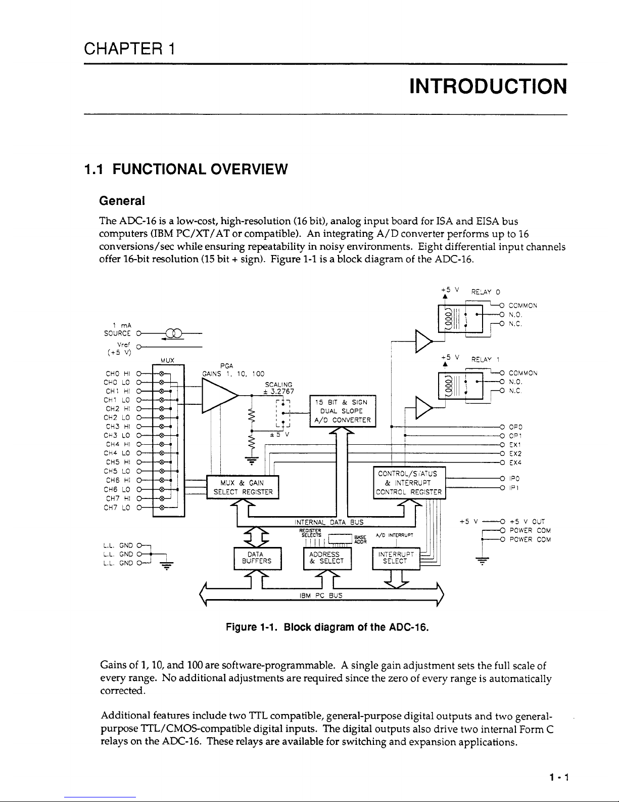
The AX-16 is a low-cost, high-resolution (16 bit), analog input board for ISA and EISA bus
computers (IBM PC/XT/AT or compatible). An integrating
A/D
converter performs up to 16
conversions/sec while ensuring repeatability in noisy environments. Eight differential input channels
offer 16-bit resolution
(15
bit + sign). Figure
1-1
is a block diagram of the ADC-16.
1 mA
SOURCE
O--
-
Vref
r,
(+5
V)
MUX
CHO HI
CHO
LO
CHI HI
CH1
LO
CH2 HI
CH2
LO
CH3 HI
CH3 LO
CH4
HI
CH4
LO
CH5 HI
CH5
LO
CH6 HI
CH6
LO
CH7 HI
CH7
LO
L.L.
GND
L.L. GND
L.L.
GND
GAINS
1,
10.
100
I
SCALING
fi
-
i
3.2767
I
.,
17
0
CONTROL/SiATUS
MUX
&
GAIN
&
INTERRUPT
SELECT REGISTER CONTROL REGISTER
I I
INTERNAL
DATA
aus
COMMON
N.3.
N.C.
COMMOlv
N.O.
N.C
OPD
C=:
EX1
EX2
EX4
IPO
IP
1
+5
V
OUT
POWER COU
POWER COM
IUI
IBM
PC
BUS
Figure
1-1.
Block
diagram
of
the
ADC-16.
Gains of
1,10,
and
100
are software-programmable. A single gain adjustment sets the full scale of
every range.
No
additional adjustments are required since the zero of every range is automatically
corrected.
Additional features include two
TTL
compatible, general-purpose digital outputs and two general-
purpose TTL/CMOScompatible digital inputs. The digital outputs
also
drive two internal Form C
relays on the ADC-16. These relays
are
available for switching and expansion applications.
1-1
Page 7
ADC-16
USER
GUIDE
Three more digital outputs become available when the optional STA-EX8 expansion multiplexer(s)
is
not used. A
1
mA,
high-precision current source with a compliance of -10 V to
+4
V
allows excitation
of resistance-based transducers such as RTDs.
All
connections to the ADC-16 pass through a standard
37-pin D connector using the manufacturer's C-1800 cable.
Optional equipment for the ADC-16 includes two screw-termination boxes: the STA-U and the STA-
EX8. The STA-U provides access to all ADC-16 interface signals via miniature screw-terminal
connectors. The STA-EX8 provides access to all ADC-16 interface signals via miniature screwterminal connectors, and it provides eight additional input channels. Up to eight STA-EX8s may be
added
to
an ADC-16, resulting in
64
fully differential channels.
Operating
Modes
A/D
Transfers
The ADC-16 conducts A/D conversions on a self-timing basis; the conversions progress as quickly as
the A/D circuitry can operate. When a previous conversion ends, the Driver starts another.
This
process continues until the scan is complete.
When a STart/Stop array is in use, the number of conversions is equal to the number of channels
specified in the array. This number can be up to
64
if eight STA-EX8s are in the system.
When a Channel/Gain array is in use, the number of conversions is equal to the number of entries in
the array.
This
number can
be
up to 256.
There are three modes of A/D operations:
SYNCHRONOUS MODE
-
where the transfers are occur in the foreground, forcing the user to
wait for the board to finish. This mode is invoked by the K-Syncstart call
(
see Chapters 6 and
7).
INTERRUPT MODE -
where the transfers occur in the background, allowing the user to execute
code until the board finishes. This mode is invoked by the K-IntStart call and tested for
completion by the K-IntStatus call (see Chapters 6 and
7).
These
two
modes require that channel and gain information
be
set into Frames using the K-SetBuf
and K-SetChanGary or K-SetStartStopG calls. For more information on Frames, refer to Section
6.6.
IMMEDIATE MODE
-
where when a single A/D operation takes place, all information is passed
via the Call parameters rather than by Frames, as in the two previous modes.
Digital Operations
Digital Input and Output operate
only
in the Immediate Mode, as described above for
Immediate
Mode
1.2
SOFTWARE OVERVIEW
This manual refers to the ADC-16 software as the
Distribution
Software.
The Distribution Software
contains a softwareinstallation program, driver files, utility files, calibration files, and programming
example files. For a list
of
these files, with descriptions, refer to the ASCII file
FILES.DOC.
1-2
Page 8
CHAPTER
1
:
INTRODUCTION
Because the Distribution Software arrives in compressed form,
it
is important that you follow the
installation instructions in Section
2.4.
You must use the installation program to uncompress these
files before you can access FILES.DOC.
The driver software supports the
Pop-up
Control Panel
and the
Cull Driver,
which are two of the three
interface options available for controlling the ADC-16. The third control interface is
Register-Level
I/O
programming. Chapter 3 describes of each of these interfaces.
Additional programming options are available in the
Advanced Software Option
(ASO)
,
which includes
the File I/O Command Driver, the Call Driver for C and Pascal, and the Dynamic Link Library for
Windows 3.X languages. Contact the manufacturer for information on this option.
NOTE:
The
README.DOC
file (in the Distribution Software), contains last-minute information
not included in this manual. READMEDOC
is
a readable ASCII file.
1.3
ACCESSORIES
STA-EX8
STA-U
C-1800
8-channel expansion multiplexer.
Standard Screw Terminal Board.
Cable to connect ADC-16 to STA-EX8 or STA-U.
ASO-ADC-16
Advanced Software Option for the ADC-16. This option includes Call
Driver for C and Pascal, the Dynamic Link Library for Windows
3.X,
and
the File
I/O
Driver. A user manual is also included.
1.4
SPECIFICATIONS
ADC-16
Board
A/D
Channels:
8
differential, expandable
to
64
with
STA-EX8 Boards.
Input Resolution:
16 bits
(15
plus a sign bit).
Coding:
Sign
plus
Magnitude (binary).
Input Ranges:
k5
V
or
k3.2768
V
Full Scale (jumper selectable).
Input Gains:
1,
10, or
100
(software-
or
jumper-selectable).
Sample Rate:
16 samples/second.
Input Settling Time:
50
p.
Input Offset:
Auto-zeroed; k10
pV
for Gain
=
100,
fl
LSB
for
Gain
=
1
or
10.
1-3
Page 9

ADC-16
USER
GUIDE
Absolute Accuracy
Gain = 1:
M.O1%
of
range typical
Gain
=
10:
f0.05%
of
range
typical
Gain
=
100:
M.05%
of
range typical
Relative Accuracy
Gain
=
l,lO,
and
100
maximum.
+_0.03%
maximum.
kO.lO% maximum.
k0.15% maximum.
Noise (Typical)
Gain = 1:
<
k1
bit
rms.
Gain
=
10:
c
+_1
bit
rms.
Gain
=
100:
<
+3
bits
rms.
Input Impedance:
Greater
than
100
MegOhms.
Input Bias Current:
50
nA max.
Common Mode Rejection:
Gain
=
1
-
100
dB
typ,
80
dB
min.
Gain
=
10
-
110
dB
typ,
86
dB
min.
Gain
=
100
-
120
dB
typ,
92
dE3
min.
Common Mode Range:
+_6
V.
Max Input Volts
w/o
Power On:
k35
VDC.
Damage:
Power
Off
k20 VDC.
DIGITAL
I/O
Digital Inputs
Number
of
Inputs:
2,
TTL/CMOS
compatible.
Logic Type:
High input returns
a
1.
Logic Levels:
Vil
=
.8
V, Vih
=
2.0
V.
Iil
=
-.2
mA, Iih
=
20
uA.
Digital Outputs
Number
of
Outputs:
5
TTL
compatible.
Logic Type:
Vol
=
.5
V rnax at 8.5 mA.
Voh
=
2.7 V min at
-0.4
mA.
Relay Outputs
Number
of
Channels:
2
Form
C.
Max Current:
2.0
A at
28
Vrms (resistive).
POWER REQUIREMENTS
+_0.005%
of
range typical
kO.012%
+5
V:
800
mA typ, 1 A max.
+12
V:
25 mA max.
-12
V:
15 mA max.
1-4
Page 10
CHAPTER
1
:
INTRODUCTION
ENViRONMENTAL
Operating Temperature: 0 to
70
OC.
Storage Temperature:
-25
to
85
OC.
Humidity: 0 to
95%
noncondensing.
PH YSiCAL
Dimensions:
9.0
x
4.2
in.
(22.9
x
10.7
cm)
Weight:
10
oz
(284
g).
STA-EX8
Board
Number
of
Inputs: 8 differential. Each
STA-EX8
board
uses
one
ADC-16
channel; up to
8
STA-EX
boards will work with a single
ADC-16.
Input Offset:
Auto-zeroed;
k10
pV
for Gain
= 100,
f1
LSB
for
Gain
= 1 or
10.
ACCURACY
Gain
=
1:
k.01%
of
Full
Scale.
Gain
=
10:
+.
1 % typ.
Gain
=
100:
2.1%
typ.
N
01s
E
(TYPICAL)
Gain
=
1:
<fl
bit
rms.
Gain
=
10:
<i2
bits
rms.
Gain
=
100:
<+15
bits
rms.
Input Impedance:
Greater than
100
Megohms.
Input Bias Current:
50
nA
max.
Common Mode Rejection:
Gain
=
1 - 100
dB typ,
80
dB min.
Gain
=
10 - 110
dB typ,
86
dT3
min.
Gain
=
100 - 120
dB
typ,
92
dB min.
Common Mode Range:
i6
V
Max
Input
Volts
w/o
Power
On:
i35 VDC.
Damage:
Power
Off
i20 VDC.
1-5
Page 11
ADC-16
USER
GUIDE
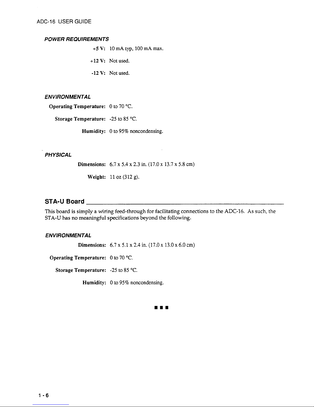
POWER REQUIREMENTS
+5
V:
10
mA
typ,
100
mA
max.
+12 V:
Not
used.
-12V:
Notused.
ENVIRONMENTAL
Operating Temperature:
0
to
70
"C.
Storage Temperature:
-25
to
85
"C.
Humidity:
0
to
95%
noncondensing.
PH YSlCAL
Dimensions:
6.7 x 5.4 x 2.3
in.
(17.0 x 13.7
x
5.8
cm)
Weight:
11
oz
(312
g).
STA-U
Board
This
board
is
simply a wiring feed-through for facilitating connections to the
ADC-16.
As
such, the
STA-U
has no meaningful specifications beyond the following.
ENVIRONMENTAL
Dimensions:
6.7 x 5.1
x
2.4
in.
(17.0 x 13.0
x
6.0
cm)
Operating Temperature:
0
to
70
"C.
Storage Temperature:
-25
to
85
"C.
Humidity:
0
to
95%
noncondensing.
1-6
Page 12
CHAPTER
2
INSPECTION, CONFIGURATION,
&
INSTALLATION
2.1
INSPECTION
After removing the wrapped Board
(ADC-16)
from its outer shipping carton, proceed as follows:
1.
Before unwrapping the Board, place one hand firmly
on
a metal portion of the computer chassis
to
discharge static electricity from yourself and the Board (the computer must be turned Off but
grounded).
2.
Carefully remove the Board from its anti-static wrapping material.
3.
Inspect the Board for signs of damage. If any damage is apparent, return the Board to the factory.
4.
Check
the
remaining contents of your package against the packing list
to
be sure your order
is
5.
When you are satisfied with preliminary inspection, you are ready to configure the Board. Refer
complete. Report any missing items to the factory immediately.
to the next section for configuration options.
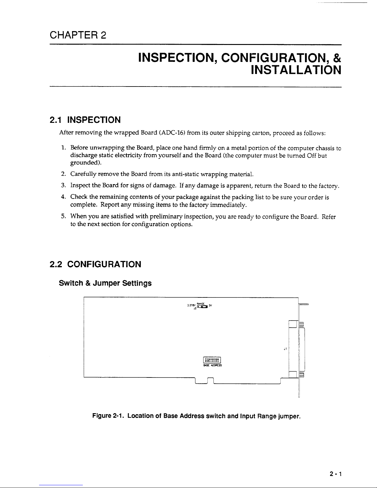
2.2
CONFIGURATION
Switch
&
Jumper
Settings
Figure
2-1.
Location
of
Base Address switch and Input Range jumper.
2-1
Page 13
ADC-16
USER
GUIDE
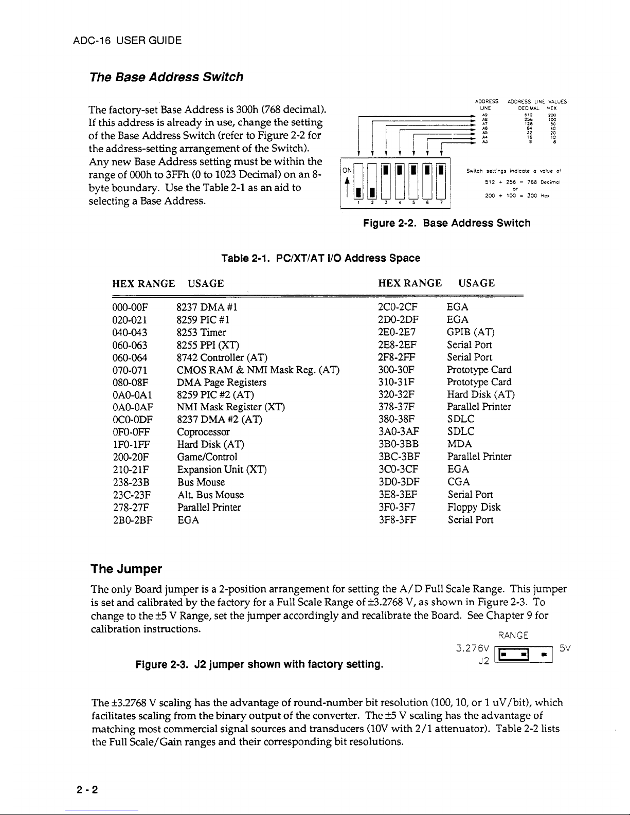
The Base Address
Switch
The factory-set Base Address is 300h (768 decimal).
If
this address
is
already in
use,
change the setting
of the Base Address Switch (refer to Figure 2-2 for
the address-setting arrangement of the Switch).
Any new Base Address setting must
be
within the
range of OOOh to 3FFh
(0
to 1023 Decimal) on an
8-
byte boundary. Use the Table 2-1 as an aid to
selecting a Base Address.
ADDRESS ADDRESS LINE VALUES
LINE
DECIMAL
*EX
512
2'X
256
>CC
64
10
16
IS
88
128
en
iiiiiii
Switch
settings
indicote
a
value
of
512
+
256
=
768
Decimol
200
+
1W
=
300
Her
or
1234567
Figure 2-2. Base Address Switch
Table
2-1.
PC/XT/AT
I/O
Address Space
HEX RANGE USAGE HEX RANGE USAGE
000-00F
020-02 1
040-043
060-063
060-064
070-07
1
080-O8F
OAO-OA
1
OAO-OAF
OCO-ODF
OFO-OFF
IFO-IFF
200-20F
210-21F
238-23B
23C-23F
278-2717
2BO-2BF
8237 DMA
#I
8259 PIC
#I
8253 Timer
8255 PPI
(XT)
8742 Controller (AT)
CMOS
RAM
&
NMI
Mask Reg.
(AT)
DMA
Page Registers
8259 PIC #2 (AT)
NMI
Mask Register
(XTj
8237 DMA #2 (AT)
Coprocessor
Hard
Disk (AT)
GameKontrol
Expansion Unit
(XT)
Bus Mouse
AIL
Bus Mouse
Parallel Printer
EGA
2CO-2CF
2DO-2DF
2EO-2E7
2E8
-
2EF
2F8-2FF
3
00-
3 OF
3 10-3 1F
320-32F
378-3717
380-38F
3AO-3AF
3BO-3BB
3BC-3BF
3CO-3CF
3DO-3DF
3E8-3EF
3FO-3F7
3F8-3FF
EGA
EGA
GPIB
(AT)
Serial Port
Serial Port
Prototype Card
Prototype Card
Hard Disk
(AT)
Parallel Printer
SDLC
SDLC
MDA
Parallel Printer
EGA
CGA
Serial Port
Floppy Disk
Serial Port
The
Jumper
The only bard jumper is a 2-position arrangement for setting the A/D Full Scale Range. This jumper
is set and calibrated by the factory for a Full Scale Range of i3.2768
V,
as shown in Figure 2-3. To
change to the
k5
V
Range, set the jumper accordingly and recalibrate the Board.
See
Chapter 9 for
calibration instructions.
RANGE
3.276v
J2
m
5v
Figure 2-3. J2 jumper shown with factory setting.
The k3.2768 V scaling has the advantage
of
round-number bit resolution
(100,10,
or 1 uV/bit), which
facilitates scaling from the binary output of the converter. The
k5
V
scaling has the advantage of
matching most commercial signal sources and transducers
(1OV
with
2/1
attenuator). Table 2-2 lists
the Full Scale/Gain ranges and their corresponding bit resolutions.
2-2
Page 14
CHAPTER
2:
INSPECTION, CONFIGURATION, & INSTALLATION
Table
2-2.
Input Range
vs.
Bit Resolutions
3.276
V
INPUT RANGE
5 V INPUT RANGE
GAIN RANGE RESOLUTION RANGE RESOLUTION
1
f3.2768
V
100
uv
i5
v
152.6
uV
10
f327.68
mV
10
uv
i500
mV
15.26
uV
100
k32.768
mV
1
uv
k50
mV
1.526
uV
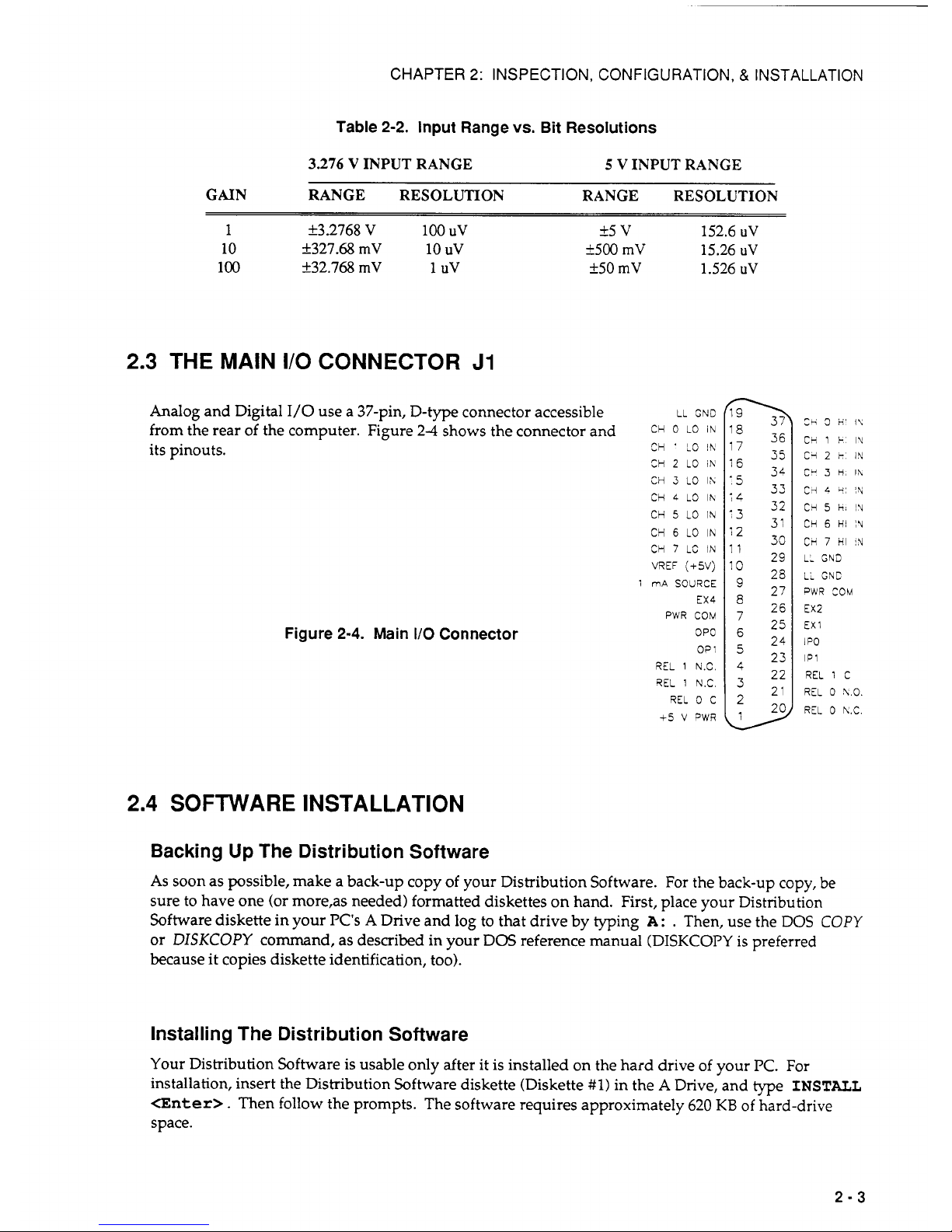
2.3
THE MAIN
I/O
CONNECTOR
J1
Analog
and Digital
I/O
use a 37-pin, D-type connector accessible
LL
GND
from the rear of the computer. Figure
2-4
shows the connector and
CH
0
LO
IN
its pinouts.
CH ' LO
IN
CH
2
LO
IN
CH
3
LO
IX
CH
4
LO
lh
CH
5
LO
IN
CY
6
LO
IN
CH
7
LC
IN
VREF
(+jV)
1
mA
SOURCE
EX4
PWR
CCM
OPO
CP
1
REL
1
N.C.
QEL
1
N.C
REL
0
C
+5
V
PWR
Figure
2-4.
Main
I/O
Connector
l8
36
I'
35
34
5
33
32
31
29
25
27
26
25
24
23
22
21
20
l2
33
I1
lo
4
>
Ch
3
H'
I\
CH
1
k
IU
C'i
2
r
IN
CY
3
H,
I\
c
4:
i\l
CH
5
it;
!A
CH
6
HI
IU
CH
7
HI
IN
LL
GND
LL
GNC
PWR
COM
EX2
EX
1
1
PO
lP1
REL
1
C
REL
0
X.0.
REL
0
K.C.
2.4
SOFTWARE INSTALLATION
Backing
Up
The Distribution Software
As
soon as possible, make a back-up copy of your Distribution Software. For the back-up copy, be
sure to have one (or more,as needed) formatted diskettes on hand. First, place your Distribution
Software diskette in your PC's
A
Drive and
log
to
that drive by typing
A
:
.
Then, use the DOS
COPY
or
DISKCOPY
command,
as
described in your DOS reference manual (DISKCOPY is preferred
because it copies diskette identification,
too).
Installing The Distribution Software
Your Distribution Software is usable only after it is installed on the hard drive of your
PC.
For
installation, insert the Distribution Software diskette (Diskette
#1)
in the A Drive, and type
INSTALL
<Enter>.
Then follow the prompts. The software requires approximately
620
KB
of hard-drive
space.
2-3
Page 15
ADC-16
USER
GUIDE
The README.DOC File
To learn of last-minute changes,
be
sure to read the ASCII file
READMEDOC.
This is an ASCII text
file that is readable with any text editor (word processor) or with the DOS
TYPE
command.
The FILES.DOC File
To learn the contents of your Distribution Software, refer to the ASCII file
FILESDOC . This file lists
and describes each of the files in the Distribution Software. This is an ASCII text file that is readable
with any text editor (word processor) or with the DOS
TYPE
command. FILES.DOC lists and briefly
describes the contents of the Distribution Software.
2.5
THE
CONFIGURATION
PROGRAM
Overview
NOTE:
Before you can run the Configuration Program, you must install the Distribution
Software (Section
2.4).
Your ADC-16 Distribution Software includes the Configuration Program
ADC16CFG.EXE , whose
purpose is to assist you in setting up Board parameters and saving them to a new or existing
configuration file. The default configuration file in your Distribution Software is
ADCI6.CFG
;
however, the Configuration Program allows you to save a set of parameters to any configuration file
you specify.
A
configuration file is a necessary reference for Call Driver programs (Chapters 6 and
7)
and for the
Pop Up Control Panel. The file contains information such as the number of ADC-16s in use, Base
Address, Range, Interrupt Level, and the number of STA-EX8s linked
to
each Board.
If
you bypass the
configuration program, the Call Driver refers to the ADC16.CFG default file.
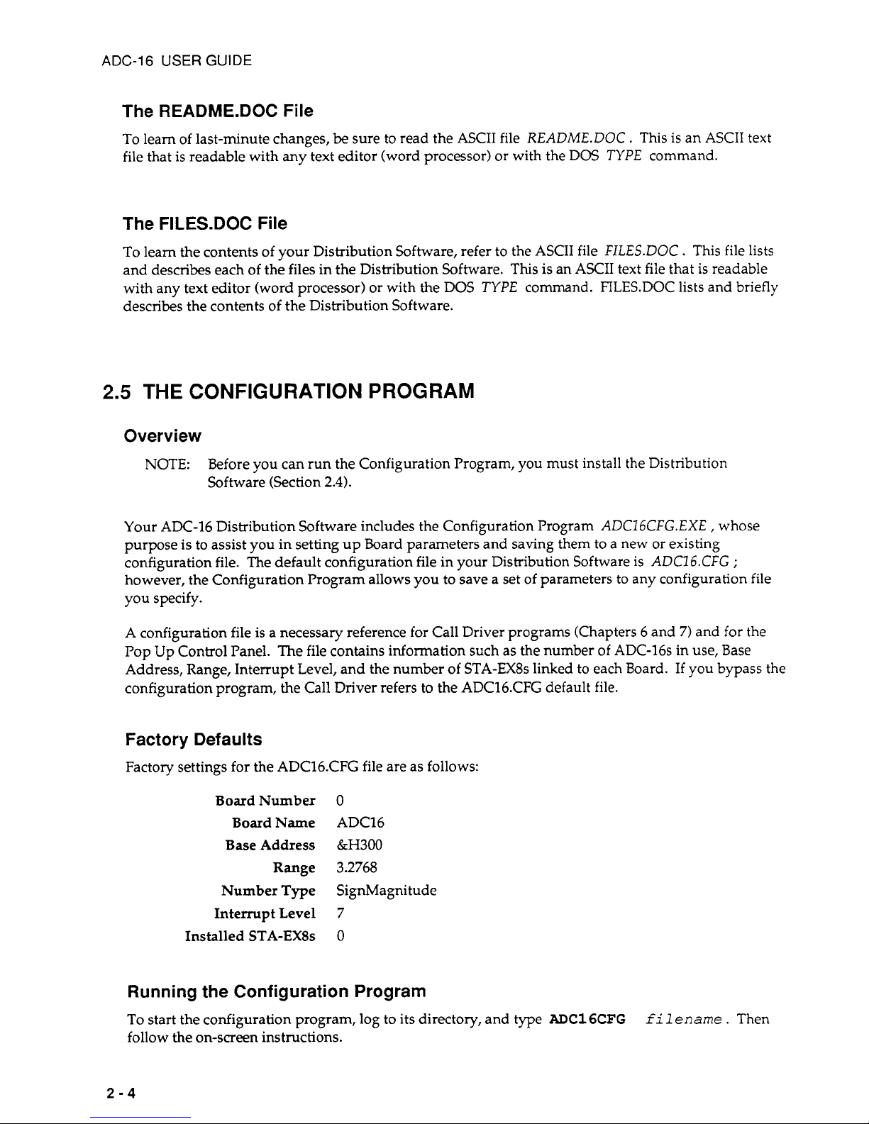
Factory Defaults
Factory settings for the ADC16.CFG file are as follows:
BoardNumber
0
Board Name
ADC16
Base Address
&H300
Range
3.2768
Number Type
SignMagnitude
Interrupt Level
7
Installed STA-EX8s
0
Running the Configuration Program
To
start the configuration program, log to its directory, and type
ADCl6CFG
follow the on-screen instructions.
f
i
1
ename
.
Then
2-4
Page 16
CHAPTER
2:
INSPECTION, CONFIGURATION, & INSTALLATION
filename
is the name of the configuration file to be modified;
it
may be an existing filename, or
it
may
be a new filename that complies with DOS file-naming conventions. The default file is ADC16.CFG.
2.6
HARDWARE
INSTALLATION
Installation
Of
The
Board
To install the ADC-16 in a PC, proceed as follows:
1.
Turn Off power to the PC and all attached equipment.
WARNING!
ANY
ATTEMPT TO INSERT OR REMOVE
ANY
ADAPTER BOARD
WITH COMPUTER POWER
ON
COULD DAMAGE YOUR
COMPUTER!
2.
Remove the cover of the PC.
3.
Choose an available option slot. Loosen and remove the retainer screw at the top of the blank
4.
Before touching the Board, place one hand on any metallic part of the PC/AT chassis (but not
on
5.
Make sure the Board switches have been properly set (refer to the configuration sections).
6. Align the Board connector with the desired accessory slot and with the corresponding rear-panel
slot. Gently press the Board into the socket. Secure the Board in place with retainer screw for
the
rear-panel adapter-plate.
7.
Replace the computer's cover.
8.
Plug in all cords and cables. Turn the power to the computer back on. You are now ready to
adapter plate. Then slide the plate up and out to remove.
any components) to discharge any static electricity from your body.
make any necessary system connections.
Installation
Of
The Expander Boxes
All connections to the ADC-16 are made through the Main I/O connector. Two interface options are
the STA-U and STA-EX8 accessory boxes.
If
your application requires access to ADC-16 interface
signals via screw terminals and eight or fewer channels of analog input use the STA-U.
If
your
application requires additional channels (more than eight), use the STA-EX8. This section describes
the installation of each. Note that the ADC-16 must already be installed for these procedures.
STA-U
Installation
The STA-U allows access to ADC-16 interface signals via screw terminals. To connect the STA-U
to
the ADC-16, obtain a C-1800 cable. Then, proceed as follows:
1.
Turn your computer off.
2.
If
the STA-U is enclosed, loosen the four comer screws and remove the top cover.
3.
Plug one end
of
the C-1800 cable into the Main
1/0
Connector of the ADC-16.
2-5
Page 17
ADC-16
USER
GUIDE
4.
Plug the other end of the C-1800 cable into one of the
two
37-pin connectors on the STA-U.
5. Make any other connections the STA-U, as required by your application.
6. Replace the cover on the STA-U and tighten the screws,
if
desired.
STA-
EX8
Installation
OVERVIEW
The STA-EX8 is a multiplexed expander box with screw connections to the ADC-16 interface signals
and the eight input channels. Up to eight STA-EX8 Boards connect to a single ADC-16 to offer up to
64
fully differential channels. The STA-EX8 has two 12-screw terminal blocks (TBI and TB2) and two
24-screw terminal blocks (TB5 and
TB6)
allowing access to the ADC-16 interface signals.
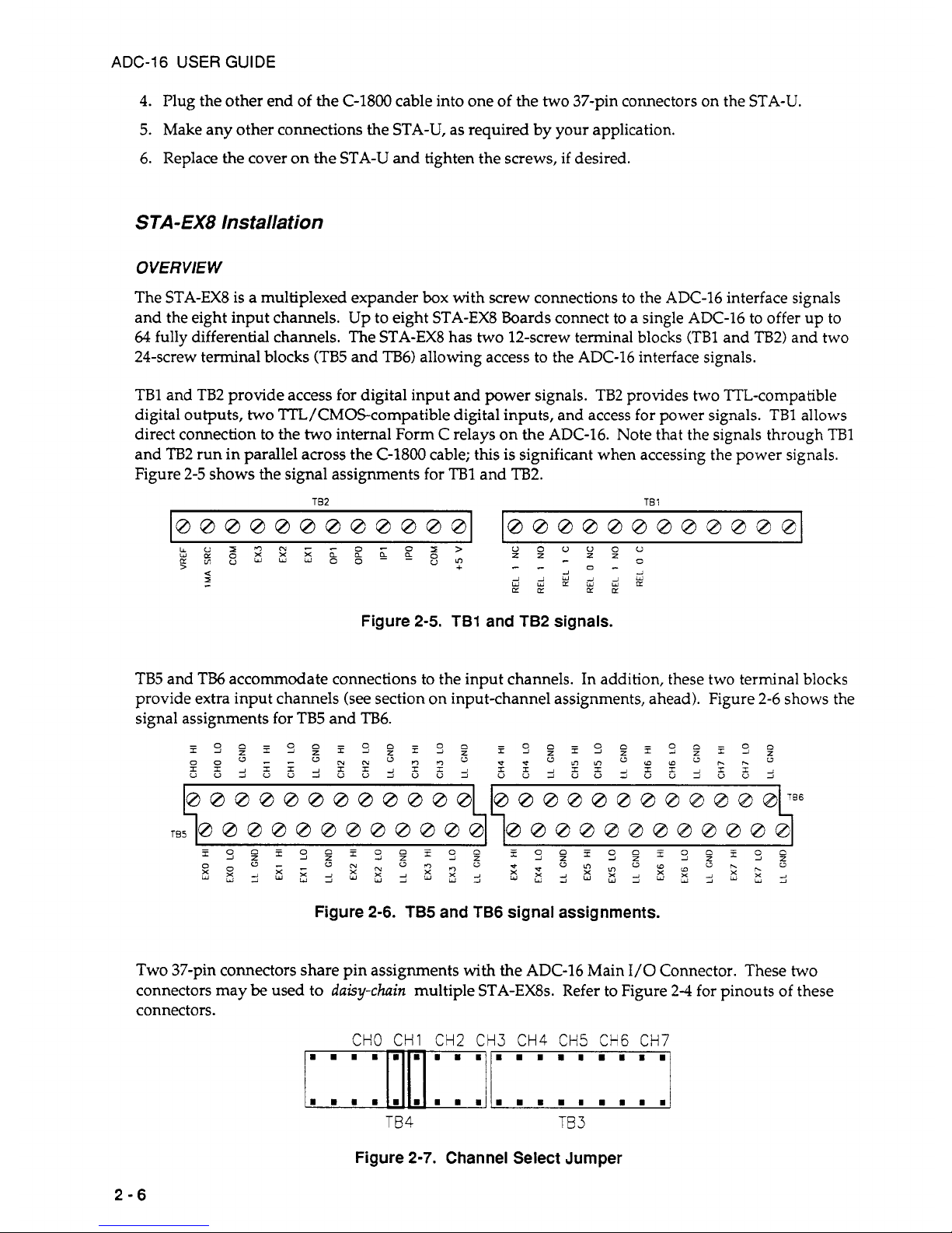
TB1 and TB2 provide access for digital input and power signals. TB2 provides two TTL-compatible
digital outputs,
two
TTL/CMOScompatible digital inputs, and access for power signals.
TBl
allows
direct connection to the
two
internal Form C relays on the ADC-16. Note that the signals through
TBl
and
TE32
run in parallel across the C-1800 cable; this
is
significant when accessing the power signals.
Figure 2-5 shows the signal assignments for
TBl
and
TB2.
TB2
TB
1
,
Figure
2-5. TB1
and
TB2
signals.
TB5 and TI36 accommodate connections to the input channels. In addition, these two terminal blocks
provide extra input channels (see section on input-channel assignments, ahead). Figure 2-6 shows the
signal assignments for TB5 and TB6.
I
I
Figure
2-6. TB5
and
TB6
signal assignments.
Two 37-pin connectors share pin assignments with the ADC-16 Main
1/0
Connector. These two
connectors may
be
used to
daisy-chain
multiple STA-EX8s. Refer to Figure 2-4 for pinouts of these
connectors.
CHO
CHI CH2 CH3 CH4 CH5 CH6
CH7
mlrl
TB4
TB
3
Figure
2-7.
Channel Select Jumper
2-6
Page 18

CHAPTER
2:
INSPECTION, CONFIGURATION, & INSTALLATION
Finally, the Channel Select Jumper (TB3 and
TB4)
determines which ADC-16 input channel the STAEX8 will use for communication. You may have up to eight STA-EX8s connected to one ADC-16.
Each STA-EX8 must have its own ADC-16 input channel. For example,
if
your application requires
two STA-EX~S, one might be assigned to Channel
0,
the other to Channel
1.
Figure
2-7
shows the
Channel Select Jumper configured for Channel
1.
INSTALLATION PROCEDURE
Obtain the required C-1800 cables, and connect STA-EX8b) to an ADC-16 as follows:
1.
Be
sure your computer is off.
2.
Remove the top cover of the STA-EX8 (loosen the four corner screws and remove; then,
lift
the
cover).
3. Set the Channel Select Jumper for an available ADC-16 input channel.
4.
Plug one end of the C-1800 cable into the ADC-16's
I/O
Connector.
5.
Plug the other end of the C-1800 cable into the first 37-pin connector
(J1)
on STA-EX8
#1.
6.
If
you are connecting more than one STA-EX8, daisy-chain the first STA-EX8 to the second. Plug
one end of a second C-1800 cable into the second 37-pin connector
(J2)
of STA-EX8
#1.
Then,
connect the C-1800 to
J1
on STA-EX8
#2.
Repeat this step for successive STA-EX8s. (Remember,
you cannot install more than eight STA-EX8s.I
7. Make all other STA-EX8 connections, as required by your application.
8.
Replace the cover(s) on the STA-EX8(s).
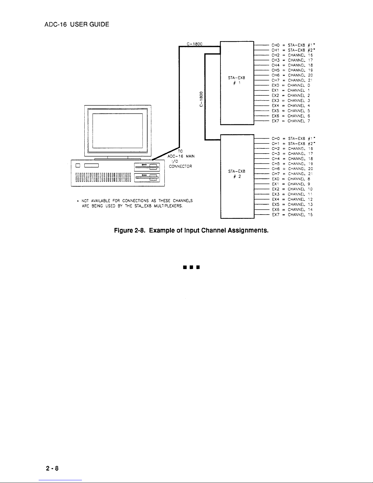
INPUT CHANNEL ASSIGNMENTS
When programming the ADC-16 to accept the data presented on the channels added by the STA-EX8
multiplexer,
you
must understand the assignment of the input channels. First, the Channel
Select
'jumper on each STA-EX8 determines which ADC-16 input channel
(CHO,
CHI, CH2, CH3, etc.) the
STA-EX8 will use for communication. The multiplexed channels
(EXO,
EX1,
etc.) are then allocated
consecutively from the assigned ADC-16 channel. For example, if your application has two STA-EX~S,
you
will assign the first STA-EX8 to ADC-16 Channel
CHO.
The multiplexed channels will then be
allocated as follows: EX0
=
Channel
0,
EX1 = Channel
1,
EX2 = Channel
2,
...
EX7 = Channel 7. Then,
you
will assign the second STA-EX8 to ADC-16 Channel CH1. The multiplexed channels
of
the
second STA-EX8 will then
be
EX0 = Channel
8,
EX1
=
Channel
9,
...
EX7 = Channel
15.
The remaining
ADC-16 input channels will then follow EX7
=
Channel
15;
that is, CH2 = Channel 16, CH3 = Channel
17,
...
CH7 = Channel
21.
Be aware that the ADC-16 input channels run in parallel across the cable.
For example, the CH2 output is associated with channel 16 on both STA-EX8s. Figure
2-8
illustrates
this arrangement.
Note that the STA-EX8 multiplexed inputs are not usable by the Pop Up Control Panel.
2-7
Page 19
ADC-16
USER
GUIDE
C-1800
AOC-16 MAIN
I/
-1
I
CONNECTOR
L
NOT AVAILABLE FOR CONNECTIONS AS THESE CHANNELS
ARE BEING
USED
BY
THE STA-EX8 MULTIPLEXERS.
0
0
I
U
z
CHO
=
STA-EX8
#I
*
CH1
=
STA-EX8
82'
CH2 = CHANNEL
15
CH3 = CHANNEL
17
CH4 = CHANNEL
18
CH5 = CHANNEL 19
CH6
=
CHANNEL 20
CH7
=
CHANNEL 21
EX0 = CHANNEL
3
EX1 = CHANNEL 1
EX2
=
CHANNEL
2
EX3 = CHANNEL
3
EX4 = CHANNEL
4
EX5 = CHANNEL
5
EX5 = CHANNEL
6
EX7 = CHANNEL 7
STA-EX8
CHO
=
STA-EX8
#l
*
CH1 = STA-EX8
#2'
CH2 = CHANNEL
:5
Cq3 = CHANhEL
17
CH4 = CHANNEL
18
CH5 = CHANNEL :9
CH5
=
CciANNEL
20
CH7 = CHANNEL
2:
EX0 = CHANNEL
8
EX1 = CHANNEL
9
EX2 = CHANNEL 10
EX3
=
CHANNEL 11
EX4 = CHANNEL
12
EX5 = CHANNEL 13
EX5
=
CHANNEL
iL
EX7 = CHANNEL 15
STA-EX8
Figure
2-8.
Example
of
Input Channel Assignments.
2-8
Page 20
CHAPTER
3
OPERATION
&
PROGRAMMING
OVERVIEW
3.1
GENERAL
The ADC-16 Distribution Software Package provides the following options:
The Pop Up Control Panel
The Call Driver for BASIC
Low-level-Register 1/0 Programming
Additional programming options, PASCAL and C support, and Windows
3.x
languages support
are
available in the Advanced Software Option.
3.2
THE POP UP CONTROL PANEL
The Pop Up Control Panel allows you direct control of ADC-16 operation without programming.
You
may configure the board to perform an analog or digital operation and to store the resultant data in a
disk file. The Pop-up uses two control panels that you may pop up with a keyboard sequence and
control using either the keyboard or mouse while under DOS or inside an applications package. This
Interface provides a quick way
to
test your board as well as to debug/monitor operation.
By
selecting
the data logging menu, you may
turn
the ADC-16 into an automatic data logging system.
Chapter
4
contains instructions for loading the Pop Up Control Panel drivers. Chapter 5 covers
operation.
3.3
THE CALL DRIVER
The Call Driver is a collection of functions (Calls) for use in programs written in Interpreted BASIC,
QuickBASIC, or QBASIC. The Calls allow you to write control programs without using register-level
programming, and they perform the most commonly used set-up and operating functions. The
Advanced Software Option provides Call Drivers for PASCAL and C and Windows
3.x
languages.
Chapter 6 lists and briefly describes each of the Call drivers and each of the Calls. Chapter
7
covers
the use of each Call and provides examples for Interpreted BASIC, QuickBASIC, and QBASIC.
3.4
LOW-LEVEL-REGISTER
I/O
PROGRAMMING
You
may also program the ADC-16 by writing directly to the on-board registers. Chapter 8 supplies
ADC-16 register maps and corresponding bit functions.
3-1
Page 21

CHAPTER
4
THE POP UP CONTROL PANEL
4.1
OVERVIEW
The Pop Up Control Panel is a software tool for setting up and monitoring the operation
of
your ADC16 board. In its monitoring capacity, the Pop-up is also useful for verifying settings and for isolating
incorrect settings or problems.
Supporting software for the Pop-up consists of the two drivers
VLEXE
and PADC16.EXE; both
drivers are in the Distribution Software. For descriptions, refer to Section
4.2.
To
use the Pop Up Control Panel, you must first load
VI.EXE
and PADC16.EXE into DOS memory.
Loading may
be
via the DOS command line or via batch file. For complete loading instructions, refer
to Sections
4.4
and
4.5.
4.2
DRIVER DESCRIPTIONS
VI.EXE
PADCl6.EXE
Virtual Instrument driver program that supports the graphics, functions,
and background operations
of
the Pop Up Control Panel for the ADC-16
and other products from the manufacturer. This driver occupies
approximately
55K
of DOS memory, and
it
must be loaded before
PADC16.EXE.
The driver program that supplies the graphics, functions, and
background operations for the ADC-16 Pop Up Control Panel. This
program loads from the
DOS
command line, and it must be loaded after
VLEXE.
After loading these drivers, you may display
or
hide the Pop Up Control Panel panels using
hot
keys,
either the default hot keys or those you assign during the PADCl6.EXE loading. Pop Up Control
Panel panels occupy the top eight character lines of the computer display; you operate their controls
by either mouse or keyboard. For complete Pop Up Control Panel opcrating instructions, refer to
Chapter
5.
4.3
DRIVER-FILE LOADING/UNLOADING OPTIONS
General
Your options for loading and unloading driver files are as follows:
Via the AUTOEXEC.BAT file (for loading only).
Via the command line.
4-1
Page 22
ADC-16 USER GUIDE
Via a batch file.
Via the SHOW.BAT utility.
With each of these options, the load/unload order must be as follows:
ProDer loadinp
-
order:
First,
load
VI.EXE
Then,
load
PADC16.EXE
Prowr unloading. order:
First,
unload
PADC16.EXE
Then,
unload
VI.EXE
Loading Via AUTOEXEC.BAT
When you load via the AUTOEXEC.BAT file, your driver files load automatically with each computer
boot-up. The files remain active until you unload them or shut down the computer.
Modify the AUTOEXEC.BAT file to include driver-loading instructions in either of two ways,
as
follows:
1.
Use a text editor. Edit AUTOEXEC.BAT to include
VI
PADC16
Note that using these instructions without switch options gives you default settings (see
Chapter
2
for default settings).
To
change the default settings, use the switch options
described in Section
4.5.
2.
Use the ATXSETUP.EXE setup utility (from the Distribution Software) to automatically
install the basic driver-loading instructions in AUTOEXEC.BAT. To use this utility,
log
to the
directory containing the Distribution Software and
type
ADCSETUY
c
Enter
>
.
Loading/Unloading From The Command Line
This method allows you to load and unload the driver files on an as-needed basis. You may
also
change your switch parameters with each loading. Unfortunately, this method can be tedious,
especially when your entry contains an error. Drivers loaded from the
DOS
command line may be
unloaded from the command line, or they may be unloaded by rebooting the
PC.
Loading/Unloading Via Batch Files
Batch files also allows you to load and unload your driver files on an as-needed basis. However, you
are confined to a single set
of
switch parameters unless you modify your start-up file or you have
additional batch files.
You
must also use separate batch files for loading and unloading. Use a text
editor to create your batch files, and be sure you insert your instructions in the correct order (refer to
LoadinglUnIoading
Order
1.
4-2
Page 23
CHAPTER
4:
THE POP UP CONTROL PANEL
Loading
Via
SHOW.BAT
The Distribution Software contains the file
SHOW.BAT
for the purpose of fast and easy batch-file
loading.
SHOW.BAT
loads
VI.EXE
and PADC16.EXE in the required order, leaving you with the
Pop
Up Control Panel on the screen.
Note that loading
PAX16
without switch options gives you the board's default settings. See Chapter
2
for a list of default settings.
4.4
SYNTAX
CONVENTIONS
Unless otherwise noted, the syntax for the driver load/unload sections Sections
4.5
and
4.6)
use
the
following character-formatting rules:
Bold
=
Indicates a mandatory entry, as follows:
BOLD
UPPER-CASE : enter exactly what is shown.
bold
lower-case
:
substitute a name, string, or value.
Italic
=
Indicates oDtional entw , as follows:
ITALIC UPPER-CASE
:
enter exactly what is shown.
ifalic lower-case
:
substitute a name, string, or value.
Plain
=
Indicates characters not reauired for execution of the command.
Plain
characters ap ear in the syntax only for clarity; whether used
or not, they have no e
P
fect.
4-3
Page 24
ADC-16
USER
GUIDE
4.5
VI.EXE:
LOADING & UNLOADING
Syntax for loading/unloading
VI.EXE
is as follows:
NOTE: Refer to Section
4.4
for syntax conventions.
path
Vf.exe
MONO
/HK
=
x
/MK
=
m
/SK
=
s
/U
where
path
DOS
path to VI.EXE. Example:
C:\ADC16\
MONO
Optional command for computers with monochromatic displays.
If
MONO
is
not specified,
COLOR
is assumed.
/HK
=
x
Help Key switch: to specify your choice of key(s) for bringing up the Help
Screen for the Pop Up Control Panel. The default Help Keys are
<
Alt
>
+
<
H
>.
x
is one, two, or three keys, as follows:
(1)
One key: any choice
of
c
A
>
through
< Z > , <
F1>
through
<
F10
>
,
<O>
through c9>,or
<Tab>,
<Esc>,or
<?>;
(2)
Two or three keys: it can be a combination of the
<
Ctrl>
and/or
<
Alt > key(s) plus any choice of
< A >
through
< Z > , <
F1>
through
<F10>,
<O>
through <9>,or
<Tab>,
<Esc>,or
<?>.
Note that your entry must
be
spelled out. For example, entering
/HK
=
F1
assigns the function key
<
F1>
to
be
the Help Key. Or entering
/HK
=
Ctrl
D
specifies that the
c
Ctrl>
and
< D >
keys must be pressed at the same time to
bring
up the Help screen.
IMK
=
m
Mode
Select Key switch: to specify whether the Pop-up Menu is to be
Keyboard or a Mouse operated. The default Mode Select keys are
<
Alt
>
+
< M > . Using the Mode Select key combination switches the Pop-up Menu
into Keyboard mode; from there, you press
c
Esc
>
to enter Mouse mode.
m
is one,
two,
or three keys, as follows:
(1)
One key: any choice of
< A >
through
< Z > , <
F1>
through
<
F10
>
,
<
0
>
through < 9
>
,
or
<
Tab
> , <
Esc
>
,
or
< ? >
;
(2)
Two or three keys: it can
be
a combination of the < Ctrl> and/or
<
Alt
>
key(s) plus any choice of
< A >
through
< Z >
,
<
F1>
through
cF10>,
<O>
through <9>,or
<Tab>,
<Esc>,or
<?>.
4-4
Page 25
CHAPTER
4:
THE
POP
UP
CONTROL PANEL
Note that your entry must be spelled out. For example, entering
/MK
=
F8
assigns the function key
<
F8
>
for Mode Select. Or entering
NK
=
Ctrl
T
specifies that the
<
Ctrl
>
and
< T >
keys must be pressed at the same time.
ISK
=
s
Instrument Select Key switch:
if
you have other ADC-16 boards installed in
your computer, this switch enables you to toggle between Pop-up Panels of
each instrument for the HELP function or for Mode selection of Keyboard
input. The default Instrument Select key is
<
Alt
>
+
<
Tab
>
.
s
is one, two, or three keys, as follows:
(1)
One key: any choice of < A > through
< Z >
, < F1>
through
<
F10
>
,
< 0 >
through
< 9 >
,
or
<
Tab
>
,
<
Esc
>
,
or
< ? >
;
(2)
Two
or three keys:
it
can be a combination of the
<
Ckl>
and/or
<
Alt
>
key(s) plus any choice of < A > through
< Z > , <
F1>
through
<
F10
>
,
<
0
>
through
< 9 >
,
or
<
Tab
>
,
<
Esc
>
,
or
< ? >
.
Note that your entry must be spelled out. For example, entering
/SK
=
F3
assigns the function key
<
F3
>
as the Mode Select key. Or entering
/SK
=
Ctrl
S
specifies that the
<
Ctrl>
and
< S >
keys must be pressed
at
the
same time.
IU
Unload switch: when
VI.EXE
is already loaded and you wish to unload
it
from
memory, you use only this switch in your instruction. For example, using the
example path given above your unload instruction will be
C:\ADC16\VI
/U
NOTE that before you can unload VI.EXE, you must first unload PADC16.EXE.
An example instruction for
VI.EXE
is
C:\VI.EXE
/HK
=
Alt
X
/MK
=
Alt
Y
/SK
=
Alt
2
You
would enter this instruction at the DOS command line or into the AUTOEXEC.BAT file. This
instruction specifies the following:
VI.EXE
is in the root directory of the C Drive
Color monitor
Helpkeysare <Alt>
+
<X>
Mode
Select
keys
are < Alt
> + < Y >
Instrument Select keys are < Alt
> + < Z >
.
When this instruction for loading VI.EXE is executed, the computer will respond with the following
display:
4-5
Page 26
ADC-16 USER GUIDE
******
V1.m
Rev
3.04
o
HELP
KEY
is
ALT
X
o
INSTRUMENT
SELECT
KEY
is
ALT
2
o
MODE SELECT
KEY
is
ALT Y
4.6 PADCI 6.EXE: LOADING & UNLOADING
Before you load PADC16.EXE, you must load
VLEXE.
Syntax for loading/unloading PADC16.EXE is
as follows:
NOTE: Refer to Section
4.4
for syntax conventions.
path
PADC16.exe
/aA
=
b
/F
=
cfgfile
/PK
=
p
/NAME
=
devname /Help
/u
The elements of this model are explained as follows (note that if you do not use the switch options,
their default values remain in effect):
path
DOS path to PADC16.EXE. Example: C:\ADC16\
/BA
=
b
Base Address: The Base Address setting for the board being loaded (refer to
base-address selection, in Chapter
2).
The default Base Address is &H300
(768
decimal).
b
is
the Base Address value. Either hex (range = &H200-&H3FO) or decimal
values are acceptable; however, if they are given in hex they must be preceded
by
an
ampersand
(&)
and an H (for example,
&H300).
Make certain the Base
Address you enter has
not
been already assigned to another device.
/F
=
cfgfile
Default Override: allows you
to
change any or all of the default
parameters discussed in the configuration section (Section
2.2)
of Chapter
2.
cfgfile
the name of a configuration file created with the ADC16CFG.EXE
utility discussed in Chapter
2.
The example file used for discussion in Chapter
2
is
ADCZ6.CFG.
/PK
=
p
Pop Up Control Panel hot key switch: when the number of installed boards is
greater than one, each instrument should have its own Pop-up key assignment.
The default Pop Up Control Panel hot key is
<
Alt
>
c
F5
>
.
p
is one, two, or three keys, as follows:
(1)
One key: any choice of < A > through
< Z > , <
F1> through
<
F10
>
,
< 0 >
through
< 9 >
,
or
c
Tab > ,
<
Esc
>
,
or
<
?
> . Note that in working
with
a
single key, the key you choose will be unusable for any other
function while CALL.EXE
is
loaded; you might therefore want to confine
your single-key choice to one of the function keys
(
<
F1> through < F10
>
).
4-6
Page 27
CHAPTER
4:
THE
POP
UP CONTROL PANEL
/NAME
=
n
/Help
IU
(2)
Two or three keys:
it
can
be
a combination of the
<
Ctrl>
and/or
<
Alt > key(s) plus any choice of < A > through
<
Z
> , <
F1>
through
<
F10
>
,
< 0 >
through
< 9 >
,
or < Tab
> , <
Esc
>
,
or
<
?
>
.
Note that your entry must
be
spelled out. For example, entering
/PK
=
F3
assigns the function key
<
F3
>
for Mode Select. Or entering
/PK
=
Ctrl
P
specifies that the < Ctrl> and < P > keys must be pressed at the same time.
Use when the number of installed boards is greater than one and you wish to
display the Pop Up Control Panel for any two of the boards simultaneously.
You
must enter
an
PADC16,EXE instruction
for
both boards--to give each
board unique hot
keys,
Base Address, and name.
n
is the name you enter for one board;
it
must be
1-8
characters. Any of the
following characters are acceptable:
<
A
>
through
<
Z
>
,
< 0 >
through
<9>,
<$>,
<&>,
<#>,
<@>,
<!>,
<%>,
<(>,
<I>,
<->,
<{>,
c
1
>
,
c
- > .
Note that
/,
\,
and * are illegal.
For example,
NAME=ADC16
Use this switch to list all command-line options for the ADC16.EXE driver.
When you use this switch, you will need no other switches, because the driver
is not installed.
Unload switch: when
you
wish to unload PADCl6.EXE from memory, use
only this switch in your instruction. For example, using the path given above
your unload instruction will
be
NOTE that you must unload PADC16.EXE before VI.EXE.
An
example instruction for PADC16.EXE
is
as follows:
C:
\ADC16\PADC16
You
would enter this instruction at the DOS command line or into the AUTOEXEC.BAT file. This
instruction specifies the following:
PADC16.EXE is in the ADC16 directory of the C Drive
With no switches, the software uses the factory-preset parameters.
When this instruction for loading PADC16.EXE is executed, the compliter responds with the following
display.
4-7
Page 28
ADC-16
USER
GUIDE
******
PADC16.EXE
popup
Driver Rev
1.00
o
popup
Hot
Key
is
ALT
F6
o
Factory
Configuration
assumed
Number
Of
Bytes
Used
By Device
:
57968
At
Memory
Segment
[llB3]
4.7
LOADING
ANSLSYS
To
obtain optimum computer performance while working with the
VI.EXE
and
PADC16.EXE
files,
your system may require access to the
DOS
ANSI.SYS
file.
ANSI.SYS
is generally included with the
files in your computer's DOS software.
To
activate
ANSI.SYS,
you must modify your computer's
CONFIG.SYS
file to include an
ANSI.SYS
loading instruction.
Your
instruction must use the syntax of
the following model:
DEVICE
=
path
ANSI.SYS
For example, if
ANSI.SYS
is in a directory called
DOS
on the D Drive, your instruction would be
DEVICE=D:\DOS\ANSI.SYS
Remember that when you alter a
CONFIGSYS
file, you must re-boot before the new changes can take
effect.
4-8
Page 29
CHAPTER
5
POP UP CONTROL PANEL OPERATION
5.1
PRELIMINARY REQUIREMENTS
Before you can use the Pop Up Control Panel, your ADC-16 board must be properly installed and
your
VI.EXE
and PADC16.EXE drivers properly loaded. For board-installation instructions, refer to
Chapter
2.
For driver-loading instructions, refer to Chapter
4.
5.2
GETTING STARTED
To
Get
Up &
Running Quickly
NOTE:
This
procedure
is
valid only when ADC-16 factory configuration is in effect for both
hardware and software and when
you
are logged to the directory containing the
Distribution Software.
1.
With the board installed,
type
SHOW
2.
Click your mouse on
ADSTART,
located at the
top
of the Panel.
You
are now acquiring samples
from channels at
16
Hz.
The data from this first channel scan should be showing on the Panel.
3.
Connect known voltages to Analog Input channels and repeat Step
2.
to put the Analog Panel
Jt
the top
of
your display.
To
Get
Up
&
Running
Via
Hot
Keys
1.
With the board installed and drivers loaded, use the hot keys to access the Pop Up Control
Panel. The default hot keys are
c
Alt
>
c
F6
> ; press these keys simultaneously to put the
Analog Panel at the top of your display.
2.
Click your mouse on
ADSTART,
located at the top right of the Panel.
You
are now acquiring
samples from channels at 16
Hz.
The data from this first channel scan should be showing on the
Panel.
3.
Connect known voltages to Analog Input channels and repeat Step
2.
5.3
IMPORTANT HOT KEY COMBINATIONS
Familiarity with the hot-key combinations can speed up operation. The following hot keys are the
default combinations; you may change any or all of them to keys of your choice.
To
change any of
these keys, refer to the switch options in the driver-loading instructions of Sections
4.4
and
4.5.
5-1
Page 30
ADC-16
USER
GUIDE
c
Alt
>
c
F6
>Pop Upmown Keys. Use these keys to show and hide the Pop Up Control Panel panels.
c
Alt
>
c H >
Help Keys. Use these keys to show the Help Panel whenever a Pop Up Control
Panel Panel is showing.
c
Alt
>
c
Tab >Next Pop Up Keys. Use these keys to move
from
Pop Up to Pop
Up when panels for multiple boards are showing.
Keyboard Mode Entry Keys. Use these keys to change to the Keyboard Entry
Mode. Use the
c
Esc
>
key to exit this mode.
c
Alt
>
c M >
5.4
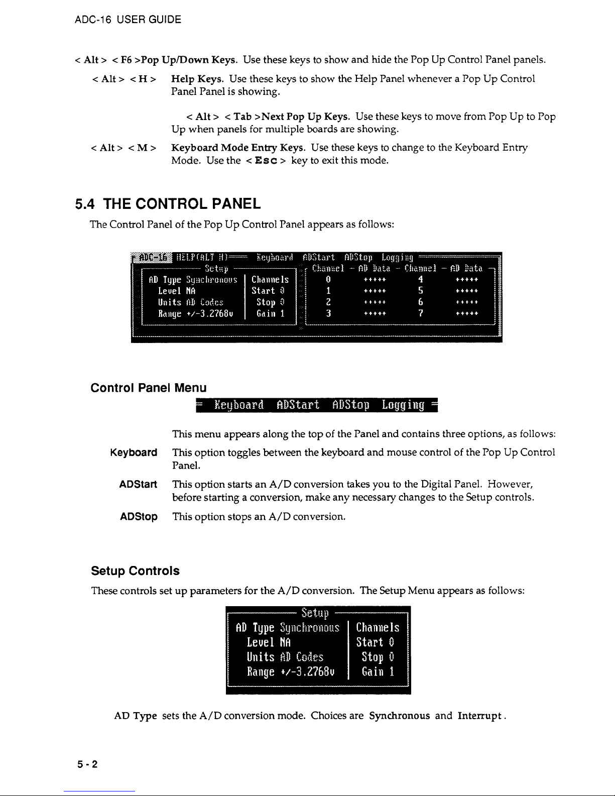
THE CONTROL PANEL
The Control Panel of the Pop Up Control Panel appears as follows:
Control Panel Menu
This menu appears along the top of the Panel and contains three options, as follows:
This
option toggles between the keyboard and mouse control of the Pop Up Control
Panel.
This
option starts an
A/D
conversion takes you to the Digital Panel. However,
before starting a conversion, make any necessary changes to the Setup controls.
This option stops an A/D conversion.
Keyboard
ADStart
ADStop
Setup Controls
These controls set up parameters for the A/D conversion. The Setup Menu appears as
follows:
AD
Type sets the
A/D
conversion mode. Choices are
Synchronous
and Interrupt.
5-2
Page 31

CHAPTER
5:
POP UP CONTROL PANEL OPERATION
Level
is active only when the
AD
Type is Interrupt. Choices are
2,
3,
4,5,7,10,11,
and
15.
Units
selects
AD
Codes
or
Volts.
Start
selects the Start Channel for the A/D conversion. The Start Channel may range from
0-7;
however, it can
be
no greater than the number specified for the Stop Channel.
Stop selects the Stop Channel for the
A/D
conversion.
Gain
Selects the gain for the
A/D
conversion. Choices are
1,
10,
and
100.
Channel - A/D Data
The monitor panel for the
A/D
conversion(s) appears as follows:
Only the channels specified by Start and Stop (under Setup)
will
show results. These results update
with each conversion cycle.
5.5
THE
DATA
LOGGING PANEL
The Data Logging Panel appears as follows:
Data Logging Menu
This menu appears along the top of the Logging Panel and contains 3 options as
follows:
This option toggles between the keyboard and mouse control
of
the Control Panel.
This
option starts the Logging function and StopLog is displayed.
If
StopLog is
selected then StartLog is displayed and logging
is
stopped.
Displays the Main Control Panel Screen.
Keyboard
StartLog
Main
...
5-3
Page 32

CHAPTER
6
THE
CALL
DRIVER
6.1
GENERAL
The Call Driver is a comprehensive set of functions you may incorporate into your own application
programs. These functions provide a high-level interface to the ADC-16 and perform all required
register-level reads and writes.
The
Call Driver is compatible with most BASIC programming languages. Specifically, the Driver
supports the following:
Interpreted BASIC (GWBASIC, BASICA, BASIC) - Section 6.2.
QuickBASIC Versions 4.0 and 4.5 - Section 6.3.
Quick/Professional BASIC Version
7.0
and above - Section 6.3.
QBASIC - Section6.4
Example programs for each of the supported languages are included in the Distribution Software.
You
may find it helpful to refer
to
one
or
more of these example programs while reading this chapter.
Since the syntax and application of the BASIC languages are different, this chapter describes
programming in each language separately.
Section 6.5 includes a listing of Calls available in the ADC-16 driver. This section is a quick-reference
only. Detailed descriptions of the Calls are in Chapter
7.
6.2
GWBASIC, BASICA, & BASIC
Program
Flow
A
typical programming sequence is as follows:
1.
Initialize the entry pointers to the driver.
*
2.
Load the driver.
*
3. Declare and dimension all variables to be used in the program.
*
NOTE:
Failure
to
declare all variables before opening the driver will cause program pointers
to
be shifted
and
the program
to
fail.
4.
Load the ADC-16 hardware configuration, and open the driver.
*
5.
Initialize the driver and board, and establish communications between the driver and the
program.
*
6-1
Page 33

ADC-16
USER
GUIDE
6.
EITHER
a. Execute a simple ADC-16 operation.
OR
b. Select the desired group of ADC-16 operations, referred to as the group's
Frame.
Execute
these operations, taking some data.
*
Indicates that this function is performed in the "Quick-Start'' programs. (see next section).
Choose Step
6a
for simple applications such as performing a single A/D conversion or reading a
digital input port. Choose 6b for more complex operations such as an interrupt-based scan of the
multiple channels.
The following sections describe the various parts of the program flow diagram. However, many
programmers may learn faster simply by referring to the example programs in the Distribution
Software.
Quick-Start Program
To
aide in the creation of programs, the Distribution Software includes a
Quick-Starf
program, which
includes all driver loading, pointer definition, and ADC-16 initialization. For interpreted BASIC, the
Quick-Start program is
ADC16.BAS
.
The program is in standard BASIC source code with an
Insert
Your
Code
Here
section.
When you begin a program, it will
be
easiest to begin with the Quick-Start program and add new
sections to the existing code. The alternative is to struggle through rewriting the driver, pointer, and
initialization code.
Initializing Pointers And Loading The Driver
The last part
of
Section 6.2 contains a listing of an Interpreted BASIC example program.
You
may
wish to refer to this example program during the discussions in this section.
In Interpreted BASIC, the driver and a number of pointers to the driver must
be
loaded within the
program itself. The entry-point variables must
be
loaded at this time (each command has a unique
entry point).
This
is performed by a subroutine in ADC16.BAS. Since there are several entry points,
it
is recommended that the ADC16.BAS Quick-Start program (or one of the example programs) be used
as the starting point for new programs.
This
will ensure the correct loading of pointers. The following
statement calls the subroutine that loads the driver entry points.
260
GOSUB
710
7
10
&Cl6DEVOPEN%=O
720 ADCl6GE!FDEVHANDLE%=3
xxx
RETURN
6-2
Page 34

CHAPTER 6 THE CALL DRIVER
The following statements then load the driver.
270
DEF SEG = &€I9000
2
8
0
BLOAD "ADC16. BIN",
0
This
code loads the driver at 9000h (at the 576K segment) and is usually a good choice. However,
computers with
512
KB
or less memory will require loading the driver at a lower address (for
example, 4000h or 5000h).
Initializing The Variables
You
must declare all your program variables before opening the driver. Using an undeclared variable
during the program will move the entry points and cause the program to fail. Examples of
declarations are as follows:
340 ADCl6
=
0
'declare
ADC16
as
real
370 DIM ADValue%(2)
'declare
an
integer
array
390 NumDfBrds%=O: ErrFlag%=O: BrdNum%=O
'declare
integers
400
GAIN%=O:
CHAN%=O
410
N$='"'
'declare
W$
string
402
VEL=O:DIRECT=O:TEMP=O
'declare
application
'dependent
variables
Opening The Driver
The next step opens the driver, and reads the current configuration file (see Section 2.6) for the ADC-
16 hardware (Base Address, Interrupt Level, input configuration). The ADCl6DevOpen command
performs this function, which is demonstrated (along with other required initialization functions) in
the example program in Section 6.3. The
syntax
for the ADC16DevOpen function
is
shown below:
500
N$ = "ADC16.CFG"
+
CHR$(O)
'Setup
filename
510
CALL
ADCl6DevOpen% (N$, NumOfBrds%, ErrFlag%) 'Read ADC-16
520
'configuration
file
Establish Communications Between The Driver & Program
To allow the use of multiple boards, the
Calls
require a board identifier for each board. The board
identifier is called a
Device Handle,
or simply
Handle
.
Without Handles, a
KADRead
command
would not know which board (in a multi-board system) to call.
The Handle for each board is returned by the
ADC16GetDevHandle
command after a successful call
to
ADC16DevOpen,
which is included in the Quick-Start programs. Additional information on the
ADCl6GetDevHandle
function (and concept) is as follows:
SINGLE
BOARD
SYSTEMS
In single-board systems, obtain the Handle via the ADCl6GetDevHandle function. The following
examples show use of the Handle.
6-3
Page 35

ADC-16
USER
GUIDE
First, get the Handle, as follows:
539 BrdNum%
=
0 '0
since only 1 board in
system
540
CALL
ADC16GetDevHandle%(BrdNum%,Dev€Iandle,ErrFlag%)
Subsequent calls use the variable
DevHandle
to select the installed
ADC-16.
You
may change the variable name
DeuHandle
to make the program easier to read. For example, the
following program lines reflect a variable change from
DeuHundIe
to
ADCZ
6
.
539
Bra=%
=
0
'0
since only 1 board in system
540
CALL
ADC16GetDevHandle%(BrdNum%,ADCl6,ErrFlag%)
MULTIPLE BOARD SYSTEMS
In systems with more than one
board,
you must use more than one Handle. The following example
shows how to obtain and use Handles in a system with two
ADC-16s.
530
BrdNum%
=
0
'First ADC-16 board
540
CALL
ADC16GetDevHandle%(BrdNuxi%,ADCl6A,ErrFlag%)
550 BrdNum% = 1 'Second ADC-16 board
560
CALL
ADCl6GetDevHandle% (BrdNum%, ADCl6B, ErrFlag%)
NOTE:
In this example, declaration of variables
ADC16A
and
ADC16B
should be in the variable-
declaration section.
Subsequent function calls will use either the
ADC16A
or
ADCl6B
Handle to determine the selected
board.
Immediate Execution Commands & Frames
Two
types
of Call commands may
be
used to control the
ADC-16
once the driver is installed and the
Board initialized. These are
Immediate
Operation
commands and
Setup
or
Frame
commands.
IMMEDIATE OPERATION COMMANDS
A
variety of single-function commands may
be
executed without any prior setup. The simplest of
these is
KADRead
,
which specifies an input channel, an input gain, and then performs a single
A/D
conversion. The syntax for
this
command is as follows:
620 Gain%=O:Chan%=O
630
CALL
=Read% (ADC16A, man%, Gain%, ADValue%
(0)
,
ErrFlag%)
640
PRINT
"Board 1 returned",ADValue%
(0)
Note that the
ADVulue%(O)
must
be
defined as an integer array. The
ADCl6A
Handle is a single-
precision, real variable and must
be
declared in the variable declaration section. The actual numeric
value of the Handle is simply a pointer within the driver and should
be
passed where required.
MULTIPLE BOARD SYSTEMS
Systems with more than one board must use more than one Handle. The following example opens the
Handles for
two
ADC-16s
and then takes an
A/D
reading from Channel 0 of the first Board and from
Channel
5
of the second.
6-4
Page 36

CHAPTER 6 THE CALL DRIVER
530 BrdNum%
=
0
'First ADC-16 board
540 CALL
ADC16GetDevHandle%(BrdNum%,ADCl6A,ErrFlag%)
550 BrdNum% = 1 Second ADC-16 board
560 CALL
ADC16GetDevHandle%(BrdNum%,ADCl6B,ErrFlag%)
570 man%
=
0:
Gain%
=
0
580 CALL KADRead(ADC16A, man%, Gain%, =Value%
(0)
,
ErrFlag%)
590
PRINT
"The
first
ADC-16 returned",ADValue%
(0)
600 man% = 5: Gain%
=
0
610
CALL
KADRead(ADC16B, man%, Gain%, ADValue%
(0)
,
ErrFlag%)
620
PRINT
"The second ADC-16 returned",ADValue%
(0)
Note that line
580
uses the first ADC-16 Handle as set-up in line
540,
while line
610
uses the second
Handle.
Other Immediate operation commands include
KDIRead
KDOWrite
Read the digital inputs.
Write to the digital outputs.
FRAMES
Analog Input and Digital Output allow for operation using Frames. For Digital Output the Frame is
a
means of returning the value of the Digital Output port. For Analog Input the Frame is the group of all
setup parameters used in
a
synchronous or interrupt driven operation. For example, an analog input
Frame
requires setting up the following parameters:
Input Channels to scan (Start and Stop channels).
Input Gain.
Number
of
samples.
Data buffer location.
Program flow is similar in each type of Frame. The standard program flow using Frames is as follows:
First:
Next:
Then:
Optionally:
Open or get a Frame with a KGetADFrame or KGetDOFrame
command.
Setup any parameters required within the Frame.
Execute the desired Frame function.
Check the status of the operation initiated.
The following program segment is similar to the
GWBEX7.BAS
example program included in the
Distribution Software. It may
be
helpful to refer to this example program during the following
discussion.
6-5
Page 37

ADC-16
USER
GUIDE
Example using Analog Input Frame
10
I
Synchronous A/D scan using Start / Stop / Gain parameters
20 STEP
1
:
The following is the start up code required to link to the
30 DAS Driver for all Interpreted BASIC programs. A subroutine (The
GOSUB
40 800 below) initializes a set of variables critical to the Driver.
80
90
GOSUB
800
I
Initialize entry variables
100
DEF SEG = &€I9000 Suggested addtess where to load the Driver
110
BLOAD "ADC16.BIN",O Load the driver
120
I
130
I,~~~~~,,,~,~~~~,~~~~,,,,,,,~~~~~~~~~,~-~~~~~~~~~~~~~~~~~~~~~~~~~~~~~~
140
I
150
160
170
180
190
200
210
220
230
240
250
260
27
0
280
STEP 2
:
Dimension and initialize ALL basic variables first.
Declare ALL additional program variables in this step. You must
avoid declaring and using variables on the fly.
DEVHANDLE=O Declare all handles as Reals
ADSET=O
I
Analog Input Frame
A$=''
NUMOFBRDS%=O: EWLAG%=O: BRDNUM%=O
DIM BUFFER% (20),
SAMPLES%
(2)
STARTCHAN%=O
STOPCHAN%=O
GAINCHAN%=O
X%=O
BUFFEROFFSET%
=
0
440
450
I
460
470
480
490
500
I
510
52
0
530
540
550
560
57
0
580
590
600
610
620
630
640
650
660
6-6
STEP 5 : To perform a FRAME based Analog Input function, first
get a FRAME handle and then initialize the parameters
for the
FRAME.
CALL KGETADFRAME%
(DEVHANDLE,
ADSET, ERRFLAG%)
IF ERRFLAG%
<>
0
THEN PRINT "ERROR
Is;
HEX$(ERRFLAG%) : STOP
STARTCHAN%=O:STOPCHAN%=7:GAIN%=O
CALL KSETSTARTSTOPG% (ADSET, STARTCHAN%, STOPCHAN%
,
GAIN%,
ERRFLAG%)
IF ERRFLAG%
<>
0
THEN PRINT "ERROR
Is;
HEX$(ERRFLAG%) : STOP
SAMpLES%(O)
=
0
SAMPLES
parameter ignored
BUFFEROFFSET%
=
VARPTR (BUFFER%
( 0 )
)
CALL KSETBUF% (ADSET, DATASEG%, BUFFEROFFSET%, SAMPLES%
(0)
,
ERRFLAG%)
IF ERRFLAG%
<>
0
THEN PRINT "ERROR
'I;
HEX$(ERRFLAG%) : STOP
CALL KSYNCSTART% (ADSET, ERRFLAG%)
IF ERRFLAG%
<>
0
THEN PRINT "ERROR
HEX$
(ERRFLAG%) : STOP
Display Data
FOR X%
=
0
TO (STOPC€IAN%-STARTCHAN%)
IF BUFFER%(X%)
AND
&€I8000 THEN PRINT BUFFER%(X%)
AND
&H7FFF
IF (BUFFER%(X%)
AND
&H8000)
=
0
THEN PRINT BUFFER%(X%)
*
-1
NEXT
Page 38

CHAPTER 6 THE
CALL
DRIVER
670
800
810
'
820
830
840
850
860
870
880
890
900
91
0
92
0
93
0
940
950
960
97
0
980
990
1000
1010
1020
1030
1040
1050
1060
1070
1080
1090
1100
1110
1120
1130
1140
1150
1160
Include the following in all your BASIC programs.
Initialize Driver entry point variables.
ADCl6DEVOPEN%
=o
ADCl6GETDEVHANDLE%
=
3
KGETADFRAME
%
=6
KGETDOFRAME%
=
15
KGETVER%
=
30
KDASDEVINIT%
=
33
KSETIRQMAP%
=
36
KE'REEFRAME%
=
39
KSETBUF%
=
42
KSETSTARTSTOPG%
=
54
KGETSTARTSTOPG%
=
57
KSETCHN%
=
60
KGETCHN%
=
63
KSETSTARTSTOPCHN%
=
66
KGETSTARTSTOPCHN%
=
69
KSETG%
=
72
KGETG%
=
75
KSETCHNGARY
%
=
78
KCHRFRAM3%
=
129
KINITFRAME%
=
132
KSYNCSTART
%
=
135
KINTSTART%
=
147
KINTSTATUS%
=
150
KINTSTOP
%
=
153
KGETDOCURVAL%
=
156
KMOVEDATABUF%
=
201
KADREAD%
=
213
KDIREAD%
=
219
KDOWRITE%
=
222
KFORMATCHNGARYB
=
225
KRESTORECHNGARY
%
=
228
KCLEARFRAME%
=
231
DATASEG%
=
&HFFFF
RETURN
The
KGETADFRAME
call is used to open the frame with the variable name ADSET for the ADC-16
board referred to by variable DEVHANDLE. The FRAME is filled with the start-stop channels and
gain using the call
KSETSTARTSTOPG.
The data location for the acquisition is established by
KSETBUF.
The number of samples taken in this example is determined by the start and stop channels
and the SAMPLES parameter in the
KSETBUF
call is ignored. With all the FRAME parameters
completed in ADSET, the acquisition is initiated by a call to
KSYNCSTART.
A program can define multiple frames. For example, an application may define a
FRAME
with
different start-stop channels or use
KSETCHNGARY
to define a FRAME with the gain and channel
sequence specified in a channel gain array.
6.3
QUICKBASIC
4.0
+,
INCLUDING PROFESSIONAL BASIC
7.0
+
Program
Flow
A typical programming sequence is as follows:
1.
Load the driver (from the
QB
command line).
2.
$INCLUDE: the driver function declarations.
*
3.
Declare and dimension all variables that will
be
used in the program.
*
6-7
Page 39

ADC-16
USER
GUIDE
NOTE:
Failure to declare all variables before opening the driver will cause the program
pointers to be shifted
and
will cause the program to fail!!!
4.
Load the ADC-16s hardware configuration, and open the driver.
*
5.
Initialize the driver and board, and establish communications between the driver and program.*
6. EITHER
a. Execute a simple ADC-16 operation.
OR
b. Select the desired group of ADC-16 operations, referred to as the group's
Frame.
Execute
these operations, taking some data.
*
Indicates that this function is performed in the "Quick-Start'' programs. (see next section)
Choose Step
6a
for simple applications such as performing a single A/D conversion or reading a
digital input port. Choose Step 6b for more complex operations (an interrupt-based scan of the
multiple channels).
The following sections describe the various parts of the flow diagram. However, many programmers
will learn faster by simply referring to the various example programs supplied with the
ADC-16.
Quick-Start Program
To aide in the creation
of
programs, the Distribution Software includes a
Quick-Sfarf
program. This
program includes all driver loading, pointer definition, and ADC-16 initialization; it is provided as
standard QuickBASIC source code with an
Insert
Your
Code
Here
section. The Quick-Start program
for QuickBASIC versions is
QUICKBAS.BAS
QuickBASIC Version
4.0
or greater and/or
Professional BASIC Version
7.0
or greater.
In your initial programming efforts, start with this program and add new sections to the existing code.
This should prove simpler than going through the effort to rewrite the driver, pointer and
initialization code.
Loading & Including The Driver
In QuickBASIC, the driver needs to
be
loaded at the QB command line. This procedure is as follows:
QB
/L
ADCl6QB. QLB
In Quick/Professional BASIC Version
7.0
and greater, use
QBX /L ADCl6QBX.QLB
The program itself will also need to contain the following INCLUDE statement.
QuickBASIC Versions
4.0
and
4.5
$INCLUDE: 'Q4IFACE.BI'
6-8
Page 40

CHAPTER 6 THE CALL DRIVER
Quick/Professional BASIC Version
7.0
and greater
$INCLUDE: 'Q7IFACE.BI'
Initializing The Variables
Declare all variables before opening the driver. Examples of declarations include:
DIM GAIN,
CHAN
AS INTEGER
-
declare a variable type
DIM NumDfBrds AS INTEGER
DIM ADCl6 AS LONG
-
declare long (32-bit) integers
DIM ADValue AS LONG
DIM A$
-
declare A as a string
VEL=O:DIRECT=O:TEMP=O
-
declare application variables
Don't Forget!! Declare all variables before opening the driver. Using an undeclared variable in the
program body (even the
I
in a simple
FOR
I=
1
to
10
:NEXT
I
loop) causes shifting of
device pointers and results in program failures!!
Opening The Driver
The next step opens the driver, and reads the current configuration file for the ADC-16 hardware
(Base Address, Interrupt Level, input configuration). (This file is created using the ADCl6CFG.EXE
file (described in Chapter
2).)
The ADC16DevOpen command performs this function. This function,
as well as the other required initialization functions are shown in the example program at the end of
this section. The syntax for this call is as follows:
A$
=
"ADC16.CFG"
+
CHRS(0)
'read ADC-16 config file
Derr
=
ADCl6DEVOPEN% (SSEGADD (A$),
NumOfBrds) 'execute the call
The SSEGADD command tells the driver where to look for the ADC-16 configuration information.
SSEGADD is a standard command in Prof./QuickBASIC Version
7.0
and above; but
it
is not defined
in standard QB Version
4.5
or lower. However, our Version
4.0
and
4.5
drivers define the SSEGADD
function.
Establish Communications Between The Driver & Program
To
allow the use of multiple boards, the Calls require a board identifier for each oard. The board
would not know which board (in a multi-board system) to call. The board Handle is the first
parameter in each of the AX-16 function calls.
identifier is called a
Device Handle,
or simply
Handle
.
Without Handles, a
KA
B
Read command
The Handle for each board is returned
by
the ADC16GetDevHandle command after a successful
call
to ADC16DevOpen, which is included in the Quick-Start programs. Additional information on the
ADC16GetDevHandle function (and concept) follows.
6-9
Page 41

ADC-16
USER
GUIDE
SINGLE BOARD SYSTEMS
In single-board systems, the Handle is straightforward. The Handle is obtained via the ADC-16
GetDevHandle function. The following examples describe how the Handle is used.
First, get the handle, as follows:
BrdNum
=
0
'0
since only 1 board in system
Derr
=
ADCl6GetDevHandle% (BrdNum, DevHandle)
(where Derr contains the error status)
Subsequent calls use the variable
DmHundle
to select the installed AX-16.
The variable name
DmHundle
may
be
changed to make the program easier to read. For example,
a
variable change from
DmHundle
to
ADCl6
is reflected in the following program lines.
BrdNum
=
0 '0
since only 1 board in system
Derr
=
ADCl6GetDevHandle% (BrdNum, ADCl6)
MULTIPLE BOARD SYSTEMS
In systems with more than one
board,
you must use more than one Handle. The following example
shows how the Handles are obtained and used in a system with two ADC-16s.
BrdNum
=
0
'First ADC-16 board
Derr
=
ADCl6GetDevHandle% (BrdNum, ADCl6A)
BrdNum
=
1
'Second ADC-16 board
Derr
=
ADCl6GetDevHandle% (BrdNum, ADCl6B)
Subsequent function calls will
use
the ADCl6A or ADC16B Handle for either Board to determine the
selected board.
Immediate Execution Commands & Frames
Two
types
of Call commands will control the AX-16 once the board and the driver are installed and
initialized. These are Immediate Operation commands and Setup or Frame commands.
IMMEDIA TE OPERA TION COMMANDS
Several single-function commands
may
be executed without any prior set-up. The simplest of these is
the
KADRead
command that
selects
an input channel, an input gain, and then performs a single
A/D conversion. The syntax for this command is as follows:
Chan
=
0:
Gain = 0
Derr = -Read% (DevHandle, Chan, Gain, ADValue)
PRINT
"The A/D returned", ADValue
Note that the
ADVulue
and the
DmHandle
are
Long Integers
and must
be
declared in the variable
declaration section. The ADC-16 data is returned in the least significant fifteen bits of ADValue,
if
bit
sixteen
is
zero multiply the data by minus one.
6-10
Page 42

CHAPTER 6 THE CALL DRIVER
MULTIPLE
BOARD
SYSTEMS
In systems with more than one board, more than one Handle must
be
used. The following example
opens the handles for
two
AX-16s
and then takes an
A/D
reading
from
Channel
0
of
the
Board 1 and
from Channel
5
of Board
2.
BrdNum
=
0
'First board
Derr
=
ADCl6GetDevHandle% (BrdNum, ADCl6A)
BrdNum
=
1
'Second board
Derr
=
ADC16GetDevHandle%(BrdNum,ADCl6B)
Chan
=
0:
Gain
=
0
Derr = KADRead%(ADC16A, Chan, Gain, ADValue)
PRINT "The first Board returned", ADValue
Chan
=
5:
Gain
=
0
Derr = KADRead%(ADC16B, Chan, Gain, ADValue)
PRINT "The second Board returned", ADValue
Note that the first KADread uses the Handle of the first Board as Set
up
with BrdNum
=
0,
while the
second KADRead uses the second Handle.
Other Immediate Operation commands include
KDIRead
KDO
Write
Read the digital inputs
Write the digital outputs
FRAMES
Analog
Input and Digital Output allow for operation using Frames. For Digital Output the Frame is a
means of returning the value of the Digital Output port. For Analog Input the Frame is the group of all
setup parameters used in a synchronous or interrupt driven operation. For example, an
A/D
function
requires setting up the following parameters:
Input Channels to scan (Start and Stop channels).
InputGain.
Number of samples.
Data buffer location.
A
complete set
of
selections is a
Frame.
A
complete definition of the above parameters would
be
included in an
A/D
frame. Two
types
of Frames are available for the
ADC-16,
as follows: A/D
Frames and Digital Output Frames.
Program flow is similar in each
type
of Frame, as follows:
First:
Next:
Then:
Optionally:
Open or get
a
Frame with KGetADFrame or KGetDOFrame.
Setup the parameters within the Frame.
Execute the desired Frame function.
Check the status of the operation initiated.
6-
11
Page 43

ADC-16
USER
GUIDE
The following program example
is
similar to the
QBEXAMP7.BAS
example in the Distribution
Software. It may
be
helpful to refer
to
the example during the following discussion.
Example Program Analog Input Frame
STEP
1
:
Include the supplied Q4IFACE.BI (or Q7IFACE.BI). The
1
INCLUDE file contains all function declarations supported
by
1 the driver.
1
$INCLUDE: 'Q4IFACE.BI'
1-,,,,,,,,,,,,,------------------------------------------------------------
STEP
2
:
Define
ALL
local variables required by the program here. NOTE
that you must avoid declaring and using QuickBASIC variables on the
I
fly.
DIM BUFFA(20) AS INTEGER
DIM NumDfBoards AS INTEGER
DIM DERR AS INTEGER
DIM DEVHANDLE AS LONG
DIM ADSET AS LONG
DIM STATUS AS INTEGER
DIM COUNT
AS
LONG
DIM LONGADD AS LONG
DIM StopChan AS INTEGER
DIM StartChan AS INTEGER
DIM GGAIN
AS
INTEGER
DIM BoardNm
AS
INTEGER
DIM Samples AS INTEGER
I%
=
0
BoardNum
=
0
DERR = ADCl6GETDEVHANDLE% (BoardNum, DEVHANDLE)
IF DERR
<>
0
PRINT "ERROR, DEVICE
HANDLE
IS null.
.
.'I:
STOP
SAMpLES=O
I
ADCl6 does not use the SAMPLES parameter
DERR
=
KSetBuf% (ADSET,
BUFFA(0)
,
Samples)
IF DERR
<>
0
THEN PRINT "ERROR
'I;
HEX$
(DERR) : STOP
DERR
=
KSetChnGAry% (ADSET,
IF DERR
<>
0
THEN PRINT "ERROR
'I;
HEX$
(DERR) : STOP
CHANGAINARRAY
(0)
)
StartChan=O:StopChan=7:GGAIN=O
DERR = KSetStartStopG% (ADSET, StartChan, StopChan, GGAIN)
IF DERR
<>
0
THEN "ERROR
'I;
HEX$
(DERR) : STOP
DERR
=
KSyncStart% (ADSET)
IF DERR
<>
0
THEN PRINT "ERROR
'I;
HEX$
(DERR) : STOP
6-12
Page 44

CHAPTER 6 THE CALL
DRIVER
DERR
=
KSyncStart%
(ADSET)
IF
DERR
<>
0
THEN PRINT "ERROR
'I;
HEX$
(DERR) : STOP
DERR
=
KFreeFrame% (ADSET)
IF
DERR
<>
0
THEN BEEP: PRINT "ERROR
'I;
HEX$
(DERR) : STOP
FOR
I%
=
0
TO
(STOPCHAN-STARTCHAN)
NEXT
I
PRINT
HEX$
(BUFFA
(1%)
)
END
The KGETADFRAME call is used to open the frame with the variable name
ADSET
for the
ADC-16
board referred to by variable DEVHANDLE. The FRAME is filled with the start-stop channels and
gain using the call KSETSTARTSTOPG. The data location for the acquisition is established by
KSETBUF.
The number of samples taken in this example is determined by the start and stop channels
and the
SAMPLES
parameter in the KSETBUF call
is
ignored. With all the FRAME parameters
completed in ADSET, the acquisition is initiated
by
a call to KSYNCSTART.
A
program can define multiple frames. For example, an application may define a
FRAME
with
different start-stop channels or use KSetChnGAry
to
define a
FRAME
with the gain and channel
sequence
specified
in a channel-gain array.
6.4
QBASIC
Program
Flow
A typical programming sequence is as follows:
1.
2.
3.
4.
5.
6.
Initialize the pointers to the driver.
*
Load the driver.
*
Declare and dimension all variables that will be
used
in the program. Failure to declare all
variables before opening the driver will cause the program pointers to
be
shifted and will
cause the program
to
fail!!!
*
Load the ADC-16s hardware configuration and open the driver.
*
Initialize the driver and board and establish communications between the driver and the
programming language.
*
EITHER
a. Execute a simple ADC-16 operation.
OR
b.
Select
the desired group of ADC-16 operations referred to as the group's
Frame
.
Execute the
operations, taking some data.
*
Indicates that this function is performed in the "Quick-Start'' programs. (see next section)
Choose Step
6a
for simple applications such as performing a conversion or reading a digital input
port.
Choose Step 6b for more complex operations.
The following sections will describe the various parts of the flow diagram. However, many
programmers will learn faster by referring to the example programs supplied with the
ADC-16
Distribution Software.
6-13
Page 45

ADC-16
USER
GUIDE
Quick-Start Program
To
aide in the creation of programs, the Distribution Software includes a
Quick-Start
program, which
includes all driver loading, pointer definition, and ADC-16 initialization. For interpreted BASIC, the
Quick-Start program is
QBASIC.BAS
.
The program is in standard BASIC source code with an
Insert
Your
Code
Here
section.
When
you
program the AX-16, begin
with
the Quick-Start program and add new sections to the
existing code.
This
alternative should
be
easier than rewriting the driver, pointer, and initialization
code.
Declaring The Variables
You
must declare all program variables before opening the driver. Declare each of the driver
functions as integer variables. The end of this section contains a listing of an Interpreted BASIC
example program. It may
be
helpful to refer to this example program during the discussions in this
section.
Neglecting to declare all variables will result in a program failure. Declaration examples are as
follows:
'Declare the driver
functions
DIM
DriverArray(22000)
AS
INTEGER
'Dimension an array to
'hold the driver
DIM
ADCl6DEVOPEN
AS
INTEGER
'Declare the driver
'function names
'as integer variables
DIM
KRESTORECHNGARY
AS
INTEGER
'Declare
all
variables used in the program
DIM
NumOfBrds
AS
INTEGER
-
declare
integer variables
DIM
Derr
AS
INTEGER
DIM
Gain
AS
INTEGER
DIM
Chan
AS
INTEGER
DIM
BrdNum
AS
INTEGER
DIM
A$
-
declare
A
as
a
string
DIM
ADValue
AS
LONG
-
declare
long variables
DIM
ADCl6
AS
LONG
VEL=O:DIRECT=O:TEMP=O
-
declare standard real variables
Do
not Forget!! Declare all variables prior to opening the driver. Using an undeclared variable in the
program body (even the
I
in a simple
FOR
I=
1
to
10
:NEXT
I
loop) will cause device
pointers to
be
shifted, and will result in program failures!!
Initializing Pointers & Loading The Driver
In QBASIC, the driver and a number of pointers to the driver are loaded within the program itself.
The first task
is
to
load the entry point variables (each command has a unique entry point), using a
subroutine in QBASIC.BAS. Since there are several entry points, it is recommended that the
QBASIC.BAS Quick-Start program (or one of the example programs) be used as the starting point for
new programs. This will ensure that the pointers are loaded correctly. The following statement calls
the subroutine which loads the driver entry points.
Callsetup
'call
subroutine
to
load driver pointers
6-14
Page 46

CHAPTER 6 THE CALL
DRIVER
Next, load the driver.
DEF SEG = VARSEG (DriverArray
(0)
)
BLOAD "ADC16Q. BIN",
0
Opening The Driver
The next step opens the driver and reads the current configuration file for the
ADC-16
hardware (Base
Address, Interrupt Level, input configuration).
(This
file is created using the
ADC16CFG.EXE
file
described in Chapter
2.)
ADC16DevOpen
performs
this
function. ADC16DevOpen and the other
required initialization functions are shown in the example program at the end of this section. The
syntax
for this function
is
as follows:
A$ = "ADC16.CE'G"
+
CHR$
(0)
'read
ADC-16
config file
CALL ABSOULUTE(A$, NuarOfBrds, DERR, ADCl6DEVOPEN) 'execute the call
Establish Communications Between The Driver & Program
To
allow the use of multiple boards, the function calls require an identifier for each board. A board
identifier is called a
Device
Handle
or
simply
Handle
.
Without the Handle, a KADRead command
in a multiboard system would not know which board to call. The board Handle is the last parameter
in each
of
the
ADC-16 QBASIC
calls.
The Handle for each board is returned by the ADC16GetDevHandle command after a successful
call
to ADC16DevOpen. This command is included in the Quick-Start programs. Additional information
on this function (and concept) is provided in the following paragraphs.
SINGLE
BOARD
SYSTEMS
In single-board systems the Handle is very straightforward. The Handle is obtained via the
ADC16GetDevHandle command. The following examples describe how the Handle is used.
First, Get the handle.
NumOfBrds%
=
0
'0
since only 1 board in system
CALL
ABSOLUTE(NumOfBrds,DevHandle,Derr,ADCl6GetDevHandle)
(The variable Derr contains the error status)
Subsequent calls use the variable
DeuHundIe
to select the installed
ADC-16.
The variable name
DeuHundle
may be changed to make the program easier to read. For example, a
variable change from
DeuHundle
to
ADCl6
is reflected in the following program.
BrdNum = 0
'0
since only 1 board in
system
CALL ABSOLUTE(BrdNum,ADCl6,Derr,ADCl6GetDevHandle)
6-
15
Page 47

ADC-16
USER
GUIDE
MULTIPLE BOARD
SYSTEMS
Systems with more than one boarc must use more than one Handle. The following example shows
how to obtain and use the Handles in a system with two
ADC-16s.
BrdNum
=
0
'First board
CALL
ABSOLUTE (BrdNum, ADCl6A, Derr, ADCl6GetDevHandle)
BrdNum
=
1
'Second board
CALL
ABSOLUTE (BrdNum, ADCl6B, Derr , ADCl6GetDevKandle)
Subsequent calls would use the Handles of either Board (ADC16A or ADC16B) to determine the
selected board.
TYPES
OF
CALL COMMANDS
Two
types
of Call commands are available to control the
ADC-16
once the board and the driver are
installed and initialized. These are Immediate Operation commands and Frame based commands.
IMMEDIATE OPERATION COMMANDS
Several single-function commands may
be
executed without any prior setup. The simplest
of
these
is
KADRead
,
which selects an input channel, an input gain, and then
performs
a single A/D
conversion. The syntax for
this
command is as follows:
For a single
A/D
conversion on Channel 0 with Gain Range
0,
the call would
be
Chan
=
0:
Gain
=
0
CALL
ABSOLUTE (DevHandle, Chan, Gain, ADValue, Derr,
KADRead)
PRINT
"The A/D returned", ADValue
Note that the
ADVulue
and the
DevHandle
are
Long
Integers
and must
be
declared in the variable
declaration section. The ADC-16 data is returned in the least significant fifteen bits of ADValue, if bit
sixteen is zero multiply the data by minus one.
MULTIPLE BOARD SYSTEMS
Systems with more than one board must use more than one Handle. The following example takes an
A/D
reading from Channel 0 of the first Board and Channel 5 of the second.
BrdNum
=
0
'First board
CALL
ABSOLUTE(BrdN~,ADCl6A,Derr,ADCl6GetDevHandle)
BrdNum = 1 'Second board
CALL ABSOLUTE (BrdNum, ADCl6B, Derr
,
ADCl6GetDevHandle)
Chan
=
0:
Gain
=
0
CALL ABSOLUTE(ADC16A, Chan, Gain, ADValue, Derr, KADRead)
PRINT
"The first Board returned", ADValue
Chan = 5:
Gain
=
0
CALL
ABSOLUTE(ADC16B, Chan, Gain, ADValue, Derr, KADRead)
PRINT
"The second Board returned", ADValue
6-
16
Page 48

CHAPTER 6 THE
CALL
DRIVER
Note that the first KADread
uses
the first Board Handle as set up with
BrdNum
=
0
while the second
KADRead
uses
the second Handle.
Other Immediate Operation commands include
KDIRead
KDOWrite
Read the digital inputs.
Write to the digital outputs.
FRAMES
Analog Input and Digital Output allow for operation using Frames. For Digital Output the Frame is a
means of returning the value of the Digital Output port. For Analog Input the Frame is the group of all
setup parameters
used
in a synchronous or interrupt driven operation. For example, an
A/D
function
requires setting up the following parameters:
Input Channels to scan (Start and Stop channels).
Input Gain.
Number of samples.
Data buffer location.
Program
flow is
similar in each
type
of Frame, as follows:
First:
Next:
Then:
OPtiOMlly:
Open or get a Frame with KGetADFranie or KGetDOFrame.
Setup the parameters within the Frame.
Execute the desired Frame function.
Check the status of the operation initiated.
The following program segment
is
similar
to
the
QBASEX7.BAS
example in the Distribution Software.
It
may
be
helpful to refer to the during the following discussion.
Example using Analog Input Frame
I
Synchronous
A/D
scan
using
Start
/
Stop
/
Gain
parameters
I
STEP
1
:
ALWAYS INCLUDE
AND
DECLARE THE
SUB
CallSetupO.
~--------------,---,,,,,,,,_,,,,,,,_____----------------------
1
I
It
is
SUPPLIED TO YOU WITHIN THE EXAMPLE PROGRAMS
AND
MUST
BE
INCLUDED IN ALL OF YOUR
OWN
QBASIC PROGRAMS.
DECLARE
SUB
CallSetup
()
STEP
2
:
ALWAYS DIMENSION
AN
ARRAY TO
LOAD
THE DRIVER INTO.
I
THE
DRIVER WILL OCCUPY APPROXIMATELY
42000
BYTES.
DIM DriverAry(22000)
AS
INTEGER Array
to
hold
driver
Code
..............................................................
I
STEP
3
:
ALWAYS INCLUDE THE FOLLOWING DEFINITIONS IN YOUR PROGRAM
DIM
SHARED
ADCl6DEVOPEN AS INTEGER, ADCl6GETDEVHANDLE
AS
INTEGER
DIM
SHARED
KGETADFRAME AS INTEGER, KCLEARFRAME AS INTEGER
DIM
SHARED
KGETVER
AS
INTEGER, KDASDEVINIT AS INTEGER
6-17
Page 49

ADC-16
USER
GUIDE
DIM
SHARED
KFREEFRAME AS INTEGER, KSETBUF AS INTEGER
DIM
SHARED
KSETSTARTSTOPG AS INTEGER, KGETSTARTSTOPG AS INTEGER
DIM
SHARED
KSETCHN AS INTEGER, KGETCHN AS INTEGER
DIM
SHARED
KSETSTARTSTOPCHN AS INTEGER
DIM
SHARED
KGETSTARTSTOPCHN AS INTEGER
DIM
SHARED
KSETG AS INTEGER, KGETG AS INTEGER
DIM
SHARED
KSETCHNGARY AS INTEGER
DIM
SHARED KCHKFRAME AS INTEGER
DIM
SHARED KINITFRAME AS INTEGER, KSYNCSTART AS INTEGER
DIM
SHARED
KINTSTART AS INTEGER
DIM
SHARED KINTSTATUS AS INTEGER, KINTSTOP AS INTEGER
DIM
SHARED
KGETDOFRAME
AS
INTEGER, KGETDOCURVAL AS INTEGER
DIM
SHARED
KMOVEDATABUF
AS
INTEGER
DIM
SHARED
=READ
AS INTEGER
DIM
SHARED
KDIREAD AS INTEGER, WOWRITE AS INTEGER
DIM
SHARED KFORMATCHNGARY AS INTEGER
DIM
SHARED KRESTORECHNGARY AS INTEGER
-
STEP 4 : Define
ALL
local variables
required
by
the
program.
1
Avoid &daring and using
QBASIC
variables on
the
fly.
DIM NUMOFBRDS AS INTEGER
rds
defined in
.CFG
file
DIM ERRE'LAG AS INTEGER Holds
function error returns
DIM DEVHANDLE
AS
LONG
Device Handle
-
all handles are 4 bytes
DIM ADFRAME AS LONG
DIM STARTCH AS INTEGER
DIM STOPCH AS INTEGER
DIM GAIN AS INTEGER
DIM
X
AS INTEGER
DIM DATABUFFER(20) AS INTEGER
DIM
Samples
AS LONG
DIM BRDNUM AS INTEGER
Call
Setup
Initialize
entry variables
DEF SEG = VARSEG(DriverAry(0))
Get
location
of
user array, and
BLOAD "ADC16Q. BIN",
0
Load the driver into user array
I,,---,,,,,,,,,,--,--------------------------------------------------------
!
STEP 6 : Initialize the internal data
tables
with
the
information
I
contained in the configuration file
ADCl6.CFG.
A$
=
"ADC16.CE'G"
+
CHR$(o)
CALL ABSOLUTE (A$, NUMOFBRDS, ERRE'LAG, ADCl6DEVOPEN)
IF ERRE'LAG
<>
0
PRINT "ERROR
It;
HEX$(ERRFLAG) : STOP
BRDNTJM
=
0
CALL ABSOLUTE (BRDNUM, DEVHANDLE, ERRFLAG, ADCl6GETDEVHANDLE)
IF (ERRFLAG
<>
0)
THEN PRINT "ERROR
HEX$
(ERRFLAG) : STOP
I,,,---,,,,,-,,,,,,,,,,,,,------------------------------------------------------
STEP
8
:
To
perform
a
FRAME
based Analog Input function,
first
1
get a FRAME
handle and then initialize the parameters for
I
the
FRAME.
CALL ABSOLUTE (DEVHANDLE, ADSET, ERRE'LAG, KGETADFRAME)
IF ERRFLAG
<>
0
THEN PRINT "ERROR
'I;
ERRFLAG: STOP
6-18
Page 50

CHAPTER 6 THE
CALL
DRIVER
STARTCH = 0:
STOPCH = 7: GAIN
=
0
CALL ABSOLUTE (ADSET,
IF ERRE'LAG
<>
0
THEN
SAMPLES
=
0
ADC-16
CALL ABSOLUTE (ADSET,
IF ERRE'LAG
<>
0
THEN
CALL ABSOLUTE (ADSET,
IF ERRE'LAG
<>
0
THEN
CALL ABSOLUTE (ADSET,
IF ERRFLAG
<>
0
THEN
STARTCH, STOPCH, GAIN, ERRFLAG, KSETSTARTSTOPG)
PRINT "Error
It;
ERRFLAG : STOP
does not use the SAMPLES parameter
DATABUFFER
( )
,
SAMPLES,
ERRFLAG, KSETBUF)
PRINT "Error
'';
ERRFLAG : STOP
ERRFLAG, KSYNCSTART)
PRINT "Error
#
It;
ERRFLAG; STOP
ERRFLAG, KFREEFRAME)
PRINT "Error
It;
ERRFLAG; STOP
FOR
X
=
0
TO (STOPCH-STARTCH)
NEXT
PRINT
HEX$
(DATABUFFER(X)
)
END
SUB
Callsetup
Initialize entry point Variables
ADCl6DEVOPEN
=
0
ADCl6GETDEVHANDLE = 3
KGETADFRAMF, = 6
KGETDOFRAME
=
15
KGETVER
=
30
KDASDEVINIT
=
33
KSETIRQMAP = 36
KE'REEFRAME
=
39
KSETBUF
=
42
KSETSTARTSTOPG
=
54
KGETSTARTSTOPG
=
57
KSETCHN
=
60
KGETCHN
=
63
KSETSTARTSTOPCHN
=
66
KGETSTARTSTOPCHN = 69
KSETG
=
72
KGETG
=
75
KSETCHNGARY
=
78
KCHKFRAME = 129
KINITFRAME
=
132
KSYNCSTART
=
135
KINTSTART
=
147
KINTSTATUS = 150
KINTSTOP
=
153
KGETDOCURVAL
=
156
KMOVEDATABUF
=
201
KADREAD
=
213
KDIREAD
=
219
KDOWRITE
=
222
RFORMATCHNGARY
=
225
KRESTORECHNGARY
=
228
KCLEARFRAME
=
231
END
SUB
The
KGETADFRAME
call is used to open the frame with the variable name ADSET for the ADC-16
board referred to by variable
DEVHANDLE.
The FRAME
is
filled with the start-stop channels and
gain using the call
KSETSTARTSTOPG.
The data location for the acquisition is established
by
KSETBUF.
The number of samples taken in this example is determined by the start and stop channels
and the
SAMPLES
parameter in the
KSETBUF
call is ignored.
With
all the FRAME parameters
completed
in
ADSET,
the acquisition is initiated by a call
to
KSYNCSTART.
6-19
Page 51

ADC-16
USER GUIDE
A
program can define multiple frames. For example, an application may define a
FRAME
with
different start-stop channels or use
KSETCHNGARY
to define a
FRAME
with the gain and channel
sequence specified in a channel-gain array.
6.5
LIST
OF
CALLS
This
list groups the Calls according to the categories of
Driver lnitiuliuztion , General Driver
Functions
,
Frame Management, Operating Funcfions
,
and
Frame Parameters
.
For definitions of Call Driver terms,
refer to Section
6.6.
Driver Initialization
These functions are mandatory and are typically called once, at the beginning of the application
program, before all other driver function calls. The Driver Initialization functions first verify that the
Board is at the selected base I/O address, and then they initialize both the hardware and software.
ADC-16 Driver Initialization functions are as follows:
ADC16DevOpen
ADClbGetDevHandle
KDASDevInit
Initialize a DAS driver using a configuration file.
Get a handle to the logical device associated with an adapter card.
Initialize a
DAS
driver and all aspects of the Board to a defined state.
General Function
KGetVer
Get driver specification and driver revision levels.
Frame Management
To
perform
multiple-sample Analog 1/0 or Digital Output, you must first get a Frame from the driver
through a Frame Management call. After obtaining a particular frame, you set it up using both the
Frame Management and Parameter Functions.
KGet ADFrame
KGetDOFrame
KChkFrame
KFreeFrame
KInitFrame
KClearFrame Clears the specified frame.
Get a logical Frame for Analog to Digital (A/D) operations.
Get a logical Frame for Digital Output operations.
Check the parameters in a frame for validity.
Release a no longer used frame to the driver.
Initializes the specified frame to a predefined state.
Operating Functions
iMMEDiATE OPERATlONS
The following functions do not require a Frame.
KADRead
Read a single A/D input value.
6-20
Page 52

CHAPTER
6
THE
CALL
DRIVER
KDIRead
KDOWrite
Read a single Digital Input value.
Write a single Digital Output value.
FRAME
OPERATIONS
Once a Frame is set up for a particular operation, that operation is ready to
be
initiated by a Call
to
one
of the following functions.
KSyncStart
Perform a synchronous input operation.
KIntStart
KIntStatus
Start an interruptdriven operation.
You
should specify Start & Stop
Channels, buffering, number of conversions, gain, etc. prior
to
this call.
Monitor the interrupt-driven operation associated with a particular
frame.
KIntStop
KGetDOCurVal
Halt the interrupt-driven operation associated with a particular frame.
Retrieve the digital output value assigned to a Digital Output frame.
Frame Parameters
After using a Frame Management function to obtain a Frame, you use a Frame Parameter Function to
set up its parameters. For example, after using KGetADFrame to obtain an A/D Frame, you would
use Frame Parameter functions to
set
up the analog input channels
to
be
sampled, the gain to apply to
these channels, the A/D sampling rate, etc.
KSetChn
KGetChn
Specify a channel for single channel DigitaVAnalog Input/Output
operation.
Obtain the single channel associated with a particular frame.
If
a
multiple channel frame is specified, the start channel is returned.
KSetStartStopChn
KGetStartStopChn
KSetG
Set
the Gain code.
KGetG Get the Gain code.
KSetStartStopG
KGetStartStopG
Set the Start and Stop channels for A/D input associated with a
particular frame.
Get the Start and Stop channels for A/D input associated with a
particular frame.
Specify the start channel, stop channel for A/D input, and overall gain
for a particular frame.
Obtain the start channel, stop channel for
A/D
input, and overall Gain
code associated with a particular frame.KSetChnGAry
Insert an A/D
channel gain list into a frame.
Changes format of channel gain array data from integer to unsigned
bytes.
Changes format of channel gain array data from unsigned bytes to
integer.
KFormatChnGAry
KRes toreChnG
Ary
6-21
Page 53

ADC-16
USER
GUIDE
6.6
GLOSSARY OF CALL TERMS
Frame
A Frame is a boardconfiguration template for a particular operation; it contains all the parameter
information needed to configure the board for that operation. For example, an Analog-to-Digital
(A/D) Frame contains parameters for configuring a board to perform an A/D acquisition. A/D
Frame parameters include the channel(s) to scan, the gain code, the buffer location for acquired data,
and the code for determining whether the acquisition is to
be
Interrupt driven, etc. A/D operations,
Digital Output
(DO)
operations, etc. each require a separate Frame.
Logical Device
A Device is a grouping of several frames.
Thus,
a Device may include an A/D Frame, a Digital Input
Frame, a Digital Output Frame, etc.
If
a Device also contains all the fundamental configuration data
(Base Address, Interrupt Level, etc.) for a particular board,
it
is unique to that board and is therefore a
Logical Device.
Device Handle
A
Device Handle is an identifier for a Logical Device. Each board in a system
is
assigned its own
Device Handle.
To
obtain a Device Handle for a particular board, use ADC16GetDevHandle with
the board's physical ID number.
This
Call returns a Device Handle unique to that board and its
Device.
Frame Handle
Once a Logical Device has a Device Handle, you may
specify
a Frame by a Frame Handle. A Frame
Handle is an identifier for a particular Frame and is acquired using
KGetxxFrame
(the
xx
specifies
AD or
DO)
for A/D input or Digital Output frames.
Memory Handle
A
Memory Handle identifies a block of memory assigned for a Frame. Calls that operate on memory
require a Memory Handle to designate the particular block of memory to
be
affected.
6
-
22
Page 54

CHAPTER
7
INDIVIDUAL CALL
DESCRIPTIONS
This
chapter provides a full description of each Call as used for the BASIC languages (Interpreted
BASIC, QuickBASIC, and QBASIC). Note that throughout
this
manual,
Interpreted BASIC = BASIC, BASICA
,
and
GW
BASIC
.
Descriptions are in the alphabetical order of the Call names.
Each of the descriptions discusses the following subjects:
Purpose,
format
,
in
parameters
,
out
parameters
,
return
values
,
see
also
,
comments
,
and
examples
.
In each of the Call descriptions,
format
is in the form
Returnvalue
=
FunctionName(
Parameter
1
I
***
I
Parameter
n
)
and does not reflect the syntax for any language. Under this scheme,
examples
reflect the syntaxes
for their respective languages and takes the forms
Interpreted BASIC
xxl0
CALL
FunctionName (Parameterl,
,
ParameterN, Returnvalue)
QuickBASIC
Returnvalue
=
FunctionName (Parameterl,
,
PararneterN)
QBASIC
CALL
ABSOLUTE
(Parameter1
,
,
ParanmterN, Returnvalue, E’unctionName)
**+
Note
On
Handle-Type Variables!
Many of the functions described in this chapter require the use of Handles. In Interpreted BASIC, this
variable is a single-precision floating-point value (the default variable type!); however, in QuickBASIC
and QBASIC, this value may also
be
declared as a long integer, as shown in the example programs
of
this chapter. In either case, a Handle is a 4-byte user-declared variable used strictly by the software
driver.
***
7-1
Page 55

ADC-16
USER
GUIDE
Purpose
format
entry parameters
return value
see also
comments
Examples
Interpreted
BASIC
QuickBASIC
QBASIC
ADCl 6DevOpen
Driver Initialization. Initialize a DAS driver via a configuration file.
DASErr
=
ADC16DevOpen(
CfgFile,
NumberOfBoards
)
:
Cf
gFil
e
=
you have three options:
1.
Specify
the
name of the file created with the Configuration Program (see Chapter
2
Section
2.5).
The address of the ASCII string containing configuration file name is
what is actually passed.
2.
Specify
-1
to tell the driver you are using the default factory configuration.
3.
Specify
0
(NULL
pointer) to tell the driver to use the default configuration file
name (ADC16.CFG).
NumberOfBoards
=
an integer value that determines the number of boards in the
system
(
2
or
2
);
see
comments
for restrictions.
exit parameters
None.
DASErr
=
error code number; 0 if no error
ADC16GetDevHandle.
The AX16 driver supports up to two physical boards simultaneously, except from
Interpreted BASIC where only one board is supported.
If
the configuration file
defines
two
boards, Interpreted BASIC supports only the first.
NOTE: RELAYS ARE
SET
TO NORMALLY CLOSED.
***
xxx10
A$
=
"ADC16.CFG"+CHR$(O)
xxx20
CALT,
ADClCDeVOpen%
(A$,
NumberOfBoards%, DASErr%)
A$
=
"ADC16.
CFG"+CBR$
(0)
DASErr% = ADClCDEVOPEN% (SSEGADD
(A$),
"MOE'BOARDS%)
IF
DASErr% 0 0
THEN
BEEP:
STOP:
CfgName$
=
"
ADCl6.
CFG"+CEIR$
(0)
CALL
ABSOLUTE
(CfgNameS, NumberOfBoards , DASErr, ADCl 6DevOpen)
***
7-2
Page 56

CHAPTER
7:
INDIVIDUAL CALL DESCRIPTIONS
-
ADCl GGetDevHandle
Purpose
Driver Initialization. Get a handle to the logical device associated with an adapter
card.
fOflllat
DasErr
=
ADCl6GetDevHandle
(
BoardNum, DevHandle
)
:
entry parameters
BoardNum
=
a board
ID
number. The first board is
BoardNum
=
0,
the last
is
BoardNum = NumberOfBoards-1
,
where
NumberOfBoards
is obtained from
ADC16DevOpen.
exit parameters
DevHandl
e
=
a unique handle identifier for a logical DAS device.
return value
DASErr
=
error code number; 0 if
no
error.
see also
ADC16DevOpen.
comments
ADC16GetDevHandle returns a unique device handle for identifying a specific
ADC-16 board. Multiple-board applications know how many devices are available
for the current session as a result of the previous Call using ADC16DevOpen.
Associating subsequent Calls with specific boards requires a handle.
+++
Examples
InterpretedBASIC
xxxl0
BoardNuxn% = 0
xxx20
CALL
ADClCGetDevHandle% (BoardNum%, DevHandle, DASErr%)
QuickBASIC
DASErr = ADCl6GETDEVBANDLE%
(0,
DevHandle)
'Board
#O
IF
(DasErr
0
0)
THEN
BEEP:
STOP:
QBASIC
BoardNum
=
0
DIM
DevEandle
AS
LONG
CALL
ABSOLUTE
(BoardNuxn, DevHandle, DASErr
,
ADCl
CGetDevHandle)
7-3
Page 57

ADC-16
USER GUIDE
-
KADRead
Purpose
Operating Function. Read a single A/D input value.
format
DASErr
=
KADRead(DevHandle,
Chan,
Gain,
ADValue
);
entry
PafamefefS
DevHandl
e
=
a unique identifier for a logical DAS device.
Chan
=
an integer variable that contains the number of the channel from which data
is to
be
read. For A/D frames, use
Chan
in the range of 0 to topchannel, where
topchannel
=
((#
of
STA-EX8s * 8)
+
(8
- #
of STA-EX8s))
-
1.
Gain
=
analog Gain code selection, according to the following table:
CODE
GAIN
0
1
1
10
2
100
exit
parameters
ADValue = a variable containing the data. In Interpreted BASIC, this value must be
previously DIMensioned
as
an
array of
two
integers. For QBASIC and QuickBASIC,
it is DIMensioned as a single long integer.
DASErr
=
integer variable
(0
=
No Error).
return value
see
also
KDIRead,
KDOWrite.
comments
KADRead
converts and reads a single A/D value according to the Chan and Gain
code parameters. The value returned is the absolute value of the fifteen least
significant bits of ADValue.
If
bit sixteen of ADValue is zero then multiply ADValue
by minus one.
+++
Examples
Interpreted BASIC
xxxl0
DIM
ADValue%
(2)
=20
C?UL
KADRead%
(DevHandle,
&an%,
Gain%,ADValue%
(0) , DASErr%)
QuickBASIC
DIM
ADVALUE
AS
LONG
DASErr%
=
=Read%
(DevHandle,
&an%,
Gain%,
ADVALUE)
IF
DASErr% 0 0
THEN
BEEP:
STOP:
QBASIC
DIM
ADVALUE
AS
MNG
CALL
ABSOLUTE
(DevHandle
,
Chan,
Gain,
ADValue
,
DASErr,
KADRead)
+++
7-4
Page 58

CHAPTER
7:
INDIVIDUAL CALL
DESCRIPTIONS
Purpose
format
entry parameters
exit parameters
return value
see also
comments
Examples
Interpreted
BASIC
QuickBASIC
QBASIC
KChkFrame
Frame Management. Check the parameters in a frame
for
validity.
DasErr
=
KChkE'rame(
FrameHandle,
Type
);
FrumeHundle
=
frame handle obtained from a previous KGetADFrame
or
KGetDOFrame call.
Type
=
a word-parameter flag specifying the type of operation, as follows:
Type
=
0
if checking a frame to
be
used in Sync Mode.
Type
=
1
if
checking a frame to
be
used
in Interrupt Mode,
None.
DasErr = integer variable
(0
=
No Error).
KGetADFrame, KGetDOFrame, KFreeFrame.
KChkFrame ensures that frame parameters are within established bounds for the
specified
type
of operation. Specified operation may be Synchronous (initiated by
KSyncStart
)
or Interrupt driven (initiated by KIntStart
).
KChkFrame is often
used
during development as a diagnostic tool; it is removed later.
***
XXXZO
CAU
KChkFrame%
(FrameHandle,
Type%,
DASErr%)
DASErr
=
KChkFrame%(FrameHandle,
0)
IF
DASErr
<>
0
THEN
BEEP:
STOP:
CAI&
ABSOLUTE
(FrameBandle,
0,
DASErr, KChkFrame)
***
7-5
Page 59

ADC-16
USER
GUIDE
-
KClearFrame
Purpose
Frame Management. Clear all frame parameters to their default states.
fOf7llat
DASErr
=
KClearFrame
(
FrameHandl
e
)
;
entry
parameters
FrameHandle = frame handle obtained from a previous
KGetADFrame
call.
exit parameters
None.
return value
DASErr
=
error number
(0
=
No
Error).
see also
KInitFrame.
comments
KClearFrame
performs
a
software re-initialization of all parameters within the
frame.
***
Examples
Interpreted BASIC
ax10
Call
KClearFrame%
(ADHandle,
DASErr%)
QuickBASIC
DASErr
=
KClearFrame%
(ADHandle)
IF DASErr
<>
0
THEN
BEEP:
STOP:
QBASIC
CALZl
ABSOLUTE
(ADHandle,
DasErr, KClearFrame)
***
7-6
Page 60

CHAPTER
7:
INDIVIDUAL
CALL DESCRIPTIONS
-
KDASDevInit
Purpose
General Driver Function. Initialize a DAS driver to a well-defined state.
format
DASErr
=
KDASDevInit
(
DevHandle
)
;
entry parameters
DevHandle
=
a unique identifier for a logical DAS device obtained
by
a previous
call to ADClGetDevHandle.
exit parameters
None.
return value
DASEv = integer variable
(0
=
No
Error).
see
also
ADC16DevOpen, KInitFrame.
comments
Initially,
KDASDevInit
is not required since the mandatory call to
ADC16DevOpen
effectively resets the Device parameters to their initial state. Later,
KDASDevInit
may
be
called as required; for example, when your program has just finished a
synchronous acquisition and you want to do an Interrupt operation.
By
calling
KDASDevInit
you effectively cancel all setups associated with the Synchronous
Mode. Calling
KDASDevInit
also stops all currently active operations.
Note that
KDASDevInit
initializes all driver parameters while
KInitFrame
initialize the specified frame.
NOTE:
RELAYS
ARE
SET TO
NORMALLY CLOSED.
Examples
Interpreted BASIC
-0
CAWL
KDASDevInit% (DevHandle, DASErr%)
QuickBASIC
DASErr
=
KDASDevInit% (DevHandle)
IF DASErr%
0
0
THEN
BEEP:
STOP:
QBASIC
CALL
ABSOLUTE
(DevHandle, DASErr, KDASDevInit)
7-7
Page 61

ADC-16
USER
GUIDE
Purpose
format
entry parameters
exit parameters
return value
see also
comments
Examples
Interpreted BASIC
QuickBASIC
QBASIC
KDlRead
Operating Function. Read a single Digital Input value.
DASErr
=
KDIRead(
DevHandle,
Chan,
DIValue
);
DevHandl
e
=
a unique identifier for a logical DAS device obtained by a previous
call to
ADC16GetDevHandle.
Chan
=
number for channel from which data is to
be
read (always 0 for ADC-16).
DIVulue
=
a variable that contains the data sample. In Interpreted BASIC, this
value must be previously DIMensioned as an array of
two
integers. For QBASIC
and QuickBASIC, it is DIMensioned as a single
LONG
integer.
Bit0
=
IPO;
Bit1
=
IP1.
DASErr
=
integer variable
(0
=
No
Error).
KDOWrite.
KDIRead
performs a single read operation
from
the digital input port.
+++
xxxl0
DIM DIValue%(2)
xxx20
CALL
KDIRead%
(Devtlandle,
&an%,
DIValue%
(0)
,
DASErr%)
DIM DIValue
AS
LONG
DASErr = KDIRead%(DevFfandle,
Chan,
DIValue)
IF
DASErr%
0
0
TEEN
BEEP:
STOP
PRINT
"Digital Input value
is
:
'I:
HEX$
(DIValue)
:
DIM DIValue
AS
LONG
CALL
ABSOLUTE
(DevHandle,
Chan,
DIValue, DASErr, KDIRead)
7-8
Page 62

CHAPTER
7:
INDIVIDUAL CALL DESCRIPTIONS
-
KDOWrite
Purpose
Operating Function. Write a single Digital Output value.
format
DASErr
=
-Write(
DevHandle , Chan
,
DOValue
);
entry
pafameters
DevHandl
e
=
a unique identifier for a logical DAS device obtained from a previous
call to
ADC16GetHandle.
Chan
=
number of channel from which data is to be read (always 0 for
ADC-16).
DOValue = location of a variable which contains the data sample. In Interpreted
BASIC, this value must
be
previously DIMensioned as an array of
two
integers. For
QBASIC and QuickBASIC, it is DIMensioned as a single
LONG
integer.
Bit0
=
OPO;
Bit1
=
OP1;
Bit2
=
EX1;
Bit3
=
EX2;
Bit4
=
EX4.
Digital Output on
EXI,
EX2,
and
EX4
is
disabled
if
the ADC-16 is configured (see Chapter 2 Section
2.5
1
with STA-EX8
boards.
exit parameters
None.
return
value
DASErr
=
integer variable
(0
=
No Error).
see
also
KGetDOCurVal.
comments
KDOWrite
outputs the specified
DOVaIue
contents.
KDOWrite
writes all the digital outputs at the same time.
All
data is held
in
a
single long integer in QBASIC and QuickBASIC, or a two element integer array in
interpreted BASIC.
***
Examples
Interpreted BASIC
-0
CALL
KDOWrite% (DevHandle,
man%,
DOValue%
(0) , DASErr%)
QuickBASIC
DOValue
=
12
DASErr = KDOWrite% (DovHandle,
0,
DOValue)
IF
DASErr
<>
0
TEEN
BEEP:
STOP:
QBASIC
CALL
ABSOLUTE
(Frdandle,
man,
DOValue, DASErr, KDOWrite)
***
7-9
Page 63

ADC-16
USER
GUIDE
-
KFormatChnGAry
Purpose
Frame parameter. Reformats a user channel/gain array for use by the ADC-16
driver.
fOl777af
DdSErr
=
WormatChnGAry
(
ChanGainArray
)
;
entry parameters
ChanGainArray
=
Channel Gain Array in the following form:
OFFSET
TYPE DESCRIPTION
______~~~
~~~~
0
Integer Number
Of
Enmes In This Table
(N/2)
1
Integer Channel
#1
2
Integer
Gain
Code For Channel
#1
3
Integer Channel
#2
4
Integer
Gain
Code For Channel
#2
.
Integer Channel
#
(N/2)
N
Integer Gain Code For Channel
#
(N/2)
exit parameters
None.
return value
DASErr
=
integer variable
(0 = No
Error).
see
also
KRestoreChnGAry
.
comments
For certain
A/D
acquisition modes, the user can specify different gains for different
input channels using a channel/gain array. This array is passed to the driver using
KSetChnGAry.
For the driver to accept this array, it must be in specific format;
this
format is not achievable directly from BASIC.
mormatcbnGAry
operates on the array that is actually passed to your BASIC
program, making it unreadable.
To
restore the array
so
that
it
is readable from
BASIC, use the complementary function
KRestoreChnGAry.
***
Examples
Interpreted
BASIC
-0
CALL
KFonnatChnGAry%
(ChanGainArray
(0)
,
DASErr%)
QuickBASIC
DIM ChanGainArray(20)
AS
INTEGER
ChanGainArray(0)
=
4
'
Number
of
Chan/Gain pairs
ChanGainArray
(1)
=
0
:
ChanGaiduray
(2)
=
0
Chan
0
Gain
xl
ChanGainArray(3)
=
1:
ChanGainArray(4)
=
1
'
Chan 1 Gain
x10
ChanGainAtray(5) = 2: ChanGainArray(6)
=
1
Chan 2 Gain
x10
ChanGainArray(7) = 3: CbanGainArray(8)
=
0
Chan 3 Gain
xl
DASErr
=
WormatChnGAry%
(ChanGainArray)
IF
DASErr
<>
0
THEN
BEEP:
STOP
QBASIC
CAU
ABSOLUTE
(ChanGainArray
()
,
DASErr,
KFornratChnGAry)
***
7-10
Page 64

CHAPTER
7:
INDIVIDUAL CALL
DESCRIPTIONS
-
KFreeFrame
Purpose
Frame Management. Release a frame no longer needed.
fOrI7lat
DASErr
=
WreeFrame
(
FrameHandle
)
:
entry parameters
FrumeHundle
=
frame handle obtained from a previous KGetADFrame
or
KGetDOFrame call.
exit parameters
None.
return value
DASErr
=
integer variable
(0 = No
Error).
see also
KGetADFrame, KGetDOFrame, KChkFrame.
comments
None.
***
Examples
Interpreted BASIC
-0
CALL
KFreeFramo%
(Frdandle, DASErr%)
QuickBASIC
DASErr
=
KFreeFrame%
(FrameHandle)
IF
DASErr
<>
0
!l"
BEF.P:
STOP:
QBASIC
cAI;L
ABSOLUTE
(FrameHandle, DASErr
,
KFreeFrame)
***
7-
11
Page 65

ADC-16
USER
GUIDE
Purpose
format
entry parameters
exit parameters
return value
see also
comments
KGetADFrame
Frame Management. Get a logical Frame for Analog Input
(A/D)
operations.
DASErr
=
KGotADFrame
(
DevHandl
e,
FrameHandl
e
)
;
DevHundle = device handle obtained from previous ADC16GetDevHandle call.
FrurneHandle
=
frame identification parameter for use when referencing parameters
in the frame or
by
operations that use the parameters in the frame.
DASErr
=
integer variable
(0
=
No
Error).
KChkFrame, KFreeFrame.
KGetADFrame returns a handle to a parameter list referred to as a
frame.
Frame
parameters describe all aspects of a data acquisition/conversion process. Functions
are available to set, select, or enable these parameters. For a given device, each
frame is specific to a certain type of operation.
***
Examples
Interpreted BASIC
-0
CALL
KGetADFrame% (DevHandle
,
FramaHandle,
DASErr%)
QuickBASIC
DASErr = KGetADFrame% (DevHandle, FrameHandle)
IF
(DasErr
0
0)
TEEN
BEEP:
STOP:
QBASIC
CALL
ABSOLUTE
(DevHandle,
FrameBandle,
DASErr, KGetADFrame)
***
7-
12
Page 66

CHAPTER
7:
INDIVIDUAL CALL DESCRIPTIONS
Purpose
format
entry parameters
exit parameters
return value
see also
comments
Examples
Interpreted BASIC
QuickBASIC
QBASIC
KGetChn
Frame Parameter. Obtain the Start Channel associated with a particular frame.
DASErr
=
KGetChn
(
FrameHandle,
Chan
)
:
FrumeHundle = frame handle obtained from previous
KGetADFrame
call.
Chan
=
integer variable to receive the Start Channel associated with
FrumeHundle.
DASErr
=
integer variable
(0
=
No
Error).
KSe
tChn.
If
the current frame is set
up
for multiple channels, the Start channel is returned.
+++
-0
CALL
KGetCbn%
(FrameHandle, Chan%,
DASErr%)
DASErr
=
KGetChn(FrameHandle,
man)
IF
DASErr
<>
0
THEN
BEEP:
STOP
PRINT
"Analog
Input
channel
is:
'I;
man:
CALL
ABSOLUTE
(Frdandle,
Chan,
DASErr,
KGetChn)
+++
7-
13
Page 67

ADC-16
USER GUIDE
-
KGetDOCurVaI
PurpoSe
Operating Function. Retrieve the Digital Output value currently assigned
to
the
output port of a Digital Output frame.
format
DASErr
=
KGetDoCurVal(
FrameHandle, Value
):
entry parameters
FrameHandle
=
frame handle obtained from previous KGetDOFrame call.
exit parameters
Value
=
long integer containing the current Digital Output value. Bit0
=
OPO;
Bit1
=
OP1;
Bit2
=
EX1;
Bit3
=
EX;
Bit4
=
EX4.
return value
DASEv = integer variable
(0
=
No
Error).
see also
KSetDOFrame, KDOWrite
.
comments
KGetDOCurVal reads a value
up
to 5 bits that is currently assigned to the digital
output port. This operation can take place while other background A/D operations
are in progress.
***
Examples
Interpreted BASIC
xxx20
CALL
KGetDOCurVal% (Frdandle,Value%
(0)
,
DASErr%)
QuickBASIC
DASErr = KGetDOCurVal%
(FrameHandle,
Value)
IF
DASErr
<>
0
TaEN
BEEP:
STOP
PRINT
"Current
Digital Output
value
is:
'I;
HEX$
(Value)
:
QBASIC
CALL
ABSOLUTE
(FrameHandle, Value, DASErr , KGetDOCurVal)
***
7-14
Page 68

CHAPTER
7:
INDIVIDUAL CALL DESCRIPTIONS
-
KGetDOFrame
Purpose
Frame Management. Get a logical frame for Digital Output operations.
fOfInat
DASErr
=
KGetDOFrame
(
DevHandle,
FrameHandl
e
)
;
entry parameters
DevHundle
=
device handle obtained from previous ADC16GetDevHandle call.
exit pafameters
FrurneHundle = frame identification parameter for use when referencing parameters
in the frame or by operations that use the parameters in the frame. This parameter
equals Null
(0)
if an error condition occurs.
return value
DASErr
=
integer variable
(0
=
No
Error).
see
also
KChkFrame, KFreeFrame.
comments
KGetDOFrame returns a frame handle, which identifies a parameter list referred to
as afiume. Frame parameters describe all aspects
of
a data acquisition/conversion
process. Functions are available to set, select, or enable these parameters. Each
frame is specific to a certain type of operation for a specific device.
***
Examples
Interpreted BASIC -0
CAU
KGetDOFrame% (DevEIandle, FrameHandle, DASErr%)
QuickBASIC DASErr
=
KGetDOFrame%
(DevHandle,
FrameHandle)
IF FrameEIandle
=
0
TEEN
BEEP:
STOP:
QBASIC
CAU
ABSOLUTE
(DevEandle
,
Frdandle, DASErr , KGetDOFrame)
***
7-15
Page 69

ADC-16
USER
GUIDE
Purpose
format
entry parameters
exit parameters
return value
see also
comments
KGetG
Frame Parameter. Get the Gain code for the frame.
DASErr
=
KGetG
(
FrameHandle,
Gain
)
:
FrameHandle
=
frame handle obtained from previous KGetADFrame call.
Gain
=
integer variable containing the overall (applied to all Analog Input
channels) Gain code associated with the frame.
CODE
GAIN
0
1
1
10
2
100
DASErr
=
integer variable
(0
=
No
Error).
KSetG.
KGetG returns the global Gain code currently applied to all Analog Input channels.
***
Examples
Interpreted
BASIC
-0
CALL
KGetG%
(FrameHandle,
Gain%,
DASErr%)
QuickBASIC
DASErr
=
KGetG%
(Frdandle,
Gaincode)
IF
DASErr
<>
0
THEN
BEEP:
STOP
PRINT
"The
Global
Gain
Code
is:
'I;
GainCode:
QBASIC
CALL
ABSOLUTE
(FramoHandle,
Gain,
DASErr
,
KGetG)
***
7-16
Page 70

CHAPTER
7:
INDIVIDUAL CALL DESCRIPTIONS
KGetStartStopChn
Purpose
Frame Parameter. Get the Start and Stop channels associated with a particular
frame.
format
DASErr
=
KGetStartStopChn
(
FrameHandle, StartChn, StopChn
)
;
entry parameters
FrameHandle
=
frame handle obtained from previous KGetADFrame call.
exit parameters
StartChn
=
integer variable containing the start channel associated with
FrameHandle. Limits
=
((#
of STA-EX8s
*
8)
+
(8
-
#
of
STA-EX8s))
-
1.
StopChn
=
integer variable containing the stop channel associated
with
FrameHandle. Limits
=
((#
of
STA-EX8s
*
8) + (8
-
#
of
STA-EX&))
-
1.
return value
DASEn
=
integer variable
(0
=
No Error).
see also
KSetStartStopChn.
comments
None.
***
Examples
Interpreted BASIC
xxx20
CALL
KGetStartStopChn% (FrameHandle, StartChn%, StopChn%,
DASErr%)
QuickBASIC
DASErr = KGetStartStopChn% (FrameHandle, StartChn, StopChn)
IF
DASErr
<>
0
THEN
BEEP:
STOP
PRINT
"The
Channel Scan
is
";
StartChn;
I'
to
";
StopChn:
QBAsIC
CALL
ABSOLUTE
(FrameHandle, Start&, StopChn,
DASErr,KGetStartStopChn)
***
7-17
Page 71

ADC-16
USER
GUIDE
Purpose
format
entry parameters
exit parameters
return value
see also
comments
Examples
Interpreted BASIC
QuickBASIC
QBASIC
KGetStartStopG
Frame Parameter. Obtain the start channel, stop channel and overall gain code
associated with a particular frame.
DASErr
=
KGetStartStopG(
FrameHandle,
StartChn, StopChn, Gain
)
;
FrarneHandfe = frame handle obtained from previous KGetADFrame call.
StartChn
=
integer variable containing the start channel associated with
FrameHandIe . Limits
=
((#
of STA-EX8s
*
8)
+
(8
-
#
of
STA-EX8s))
-
1.
SropChn
=
integer variable containing the stop channel associated with
FrameHandle . limits
=
((#
of STA-EX8s
*
8)
+
(8
-
#
of STA-EX8s))
-
1.
Gain
=
integer variable containing the overall gain code associated with
FrameHandle.
CODE
GAIN
0
1
1
10
2
100
DASErr
=
integer variable
(0
=
No Error).
KSetStartStopG.
None.
+++
xxx20
CALL
KGetStartStopG%(FrameHandle,StartChn%,StopChn%,Gain%,DASErr%)
DASErr
=
KGetStartStopG%(FrameHandle,
StartChn, StopChn, Gaincode)
IF DASErr
<>
0
THEN
BEEP:
STOP
PRINT
"Start:
";
StartChn;
'I
Stop:
";
StopChn;
It
Gaincode:
";
Gaincode:
CALL
ABSOLUTE
(FrameHandle, StartChn, StopChn, Gain, DASErr, KGetStartStopG)
+++
7-
18
Page 72

CHAPTER
7:
INDIVIDUAL CALL DESCRIPTIONS
KGetVer
Purpose
General Driver Function. Get driver specification and driver revision levels.
fOfllXJt
DdSErr
=
KGetVer
(
DevHandle, pSpecVer, pDriverVer
)
:
entry parameters
DevHundk
=
device handle obtained from previous ADC16GetDevHandle
call.
exit parameters
pSpecVer
=
an integer containing the version of driver specification to which
a
particular driver adheres.
pDriverVer
=
an integer containing the revision level
of
a particular driver (that is,
1.00
being initial release).
return value
DASErr
=
integer variable
(0
=
No Error).
see also
None.
comments
Both the
pSpecVer
and
pDriverVer
integers are returned in the same format. The
version number is represented in the
form
y.xx.
The y value (major Rev.
#)
is in the
high byte
of
the integer, and the
xx
value (minor Rev.
#)
is
contained in the
low
byte. The major version number is the result
of
dividing the returned integer
by
256,
while the minor version number is the result
of
taking the modulus of the returned
integer (pSpecVer
MOD
256).
***
Examples
Interpreted BASIC
-0
CAU
KGetVer% (DevHandle, pSpecVer%, pDriverVer%, DASErr%)
QuickBASIC
DASErr = KGetVer% (DevEIandle, SpecVer , DrvVer)
IF
DASErr
<>
0
THEN
BEEP:
STOP:
QBASIC
CALL
ABSOLUTE
(DevHandle, pSpecVer, pDriverVetr, DASErr, KGetVer)
***
7-
19
Page 73

ADC-16
USER
GUIDE
Purpose
format
entry parameters
exit parameters
return value
see also
comments
KlnitFrame
Frame Management. Initializes the specified frame.
DASErr
=
KInitFrame
(
FrameHandle
)
;
FrumeHundle
=
frame handle obtained from previous KGetADFrame
or
KGetDOFrame call.
None.
DASErr = integer variable
(0
=
No Error).
KDASDevInit.
KInitFrame
initializes a frame to its initial default state. When a device is newly
opened, this Call is not required because ADC16DevOpen opens and reads the
configuration file, setting all the frame parameters to their initial state. KInitFrame
may be
used
any time an operation is not in process
to
reset the parameters to that
state.
KDASDevInit initializes all device and driver functions while KInitFrame
initializes only the current frame.
KinitFrame must
be
preceded by KGetADFrame or KGetDOFrame to obtain
FrameHandIe
.
+++
Examples
Interpreted
BASIC
-0
CALL
KInitFramo%
(FrameHandle,
DASErr%)
QuickBASIC
DASErr = KInitFrame% (FrameHandle)
IF
DASErr
<>
0
'I"
BEEP: STOP:
QBASIC
CALL
ABSOLUTE
(FrameHandle, DASErr, KInitFrame%)
7-20
Page 74

CHAPTER
7:
INDIVIDUAL CALL DESCRIPTIONS
-
KlntStart
Purpose
Operating Functions. Start an operation and transfer samples using Interrupts.
fOm7at
DASErr
=
KIntStart ( FrameHandle
)
;
entry parameters
FrumeHundle
=
frame handle obtained from previous KGetADFrame call.
exit parameters
None.
return value
DASEv
=
integer variable
(0
=
No Error).
see also
KIntStatus, KIntStop.
comments
KIntStart stafis an
A/D
operation according to various parameters previously setup
through other appropriate functions. This function uses the
PC
and
ADC-16
Intempt capabilities to transfer the acquired data to the
PC
memory at speeds
limited
to
approximately
16
Hz.
This limitation occurs because of the maximum
sampling rate of the integrating
A/D
converter. Because these transfers occur in the
background, other
DAS
function may be performed simultaneously (for example,
KDIRead
or KDOWrite).
Once this operation is started,
use
KIntStatus to monitor the progress
of
the
operation and KIntStop to terminate the operation prior to its normal finish (after
the requested number
of
samples is reached).
+++
Examples
Interpreted BASIC
-0
CALL
KIntStart% (FrameBandle,
DASErr%)
QuickBASIC
DASErr
=
KIntStart% (Frdandle)
IF
DASErr
<>
0
THEN
BEEP:
STOP:
QBASIC
CALL
ABSOLUTE
(FrameBandle,
DASErr,
KIntStart)
7-21
Page 75

ADC-16
USER GUIDE
Purpose
format
entry parameters
exit parameters
return value
see
also
comments
Examples
Interpreted
BASIC
QuickBASIC
QBASIC
KIntStatus
Operating function. Monitor the status and progress of an Interrupt operation
associated with a particular frame.
DASErr
=
KIntStatus
(
FrameHandle,
Status,
Count
)
;
FromeHundZe
=
frame handle obtained from previous
KGetADFrame
call.
Status
=
integer containing status information
(1
=
Interrupt operation active,
0
=
Interrupt operation idle).
Count
=
long integer to receive current sample transfer count (samples transferred
so
far).
DASEv
=
integer variable
(0
=
No
Error).
KIntStart, KIntStop.
KIntStatus monitors the status of a previously started Interrupt operation
using
KIntStart. Use KIntStop to terminate the Interrupt operation prior to its normal
completion (when
the
requested number of samples is reached).
xxxl0
Do
CALL
KIntStatus%
(Framegandle,
Status%, Index%
(0)
,
DASErr%)
DASErr
=
KIntStatus%(FrameHandle,
Status, Count)
IF
DASErr
<>
0
THEN
BEEP:
STOP
LOOP
WHILE
STATUS
<>
0
'
Wait
until
status
is
false:
CALL
ABSOLUTE
(FrameHandle,
Status, Count, DASErr,KIntStatus)
***
7
-
22
Page 76

CHAPTER
7:
INDIVIDUAL CALL DESCRIPTIONS
-
KlntStop
Purpose
Operating function. Terminate a background Interrupt operation.
foflnat
DASErr
=
XIntStop(
FrameHandle,
Status,
Count
):
entry parameters
FrumeHundle
=
frame handle obtained from previous
KGetADFrame
call.
exitparameters
Status
=
integer to receive status information
(1
=
active,
0
=
idle).
Count
=
user long integer to receive current sample transfer count (samples
transferred
so
far).
return value
DASErr
=
integer variable
(0
=
No
Error).
see
also
KIntStart, KIntStatus.
comments
KIntStop
is used whenever
you
wish to prematurely terminate an Interrupt
operation initiated using KIntStart.
If
an Interrupt operation is in process,
it
is
stopped and the number of transferred samples is returned in
Count
;
otherwise this
function does nothing.
***
Examples
Interpreted
BASIC
xrurl0
CALL
XIntStop%
(Frdandle, Status%, Count,
DASErr%)
QuickBASIC DASErr = XIntStop% (FrameHandle, Status, Count)
IF DASErr
<>
0
THEN
BEEP:
STOP:
QBASIC
CALL
ABSOLUTE
(FrameBandle, Status, Count,
DASErr,
KIntStop)
***
7
-
23
Page 77

ADC-16
USER
GUIDE
-
KMoveDataBuf
Purpose
Memory Management. Move N bytes from one memory region to another.
format
DASErr
=
KWoveDataBuf
(
DestSeg, DestOff,
SrcSeg,
ScrOff,
Samples
)
:
entry parameters
DestSeg
=
integer Segment of the destination address.
DestOff
=
integer Offset of the destination address.
SrcSeg
=
integer Segment of the source address.
SrcOff
=
integer Offset of the source address.
Samples
=
integer for the number of bytes to transfer.
exit parameters
None.
return value
DASErr
=
integer variable
(0
=
No Error).
see also
KSetBuf.
comments
KMoveDataBuf
allows Interpreted BASIC users to transfer data to/from an internal
buffer (not easily accessible from BASIC) to/from a BASIC user array. You would
normally use this Call after a
KIntStart
operation ends.
Refer to the examples below for steps on how to transfer the first
100
A/D
samples
from an internal buffer to a BASIC array. Note that the internal buffer at
&H8000:0
was
used
to acquire data in a previous A/D operation.
If
the Destination or Source Buffer are DIMensioned arrays, the Segment value
should
be
set to
&HFFFF.
***
Examples
Interpreted
BASIC
DIY
BUF%
(100)
BUFSEG% = VARsEG(BUF%
(0)
)
'Segment
of
Basic array
BUFOFS%
=
VARPTR(BUF%
(0)
)
'Offset
of
Basic Array
IF DASErr%
0
0
THEN
BEEP:
STOP
CALL
KMoveDataBuf%(BUFSEG%,BUFOFS%,
hH8000,0,100,DASErr%)
7-24
Page 78

CHAPTER
7:
INDIVIDUAL CALL DESCRIPTIONS
Purpose
format
entry parameters
exit parameters
return value
see also
comments
Examples
Interpreted BASIC
QuickBASIC
QBASIC
KRestoreChnGAry
Frame parameter. Restore a user channel/gain array previously modified by
KFormatChnGAry
.
DASErr
=
KRestoreChnGAry(
ChanGain
(0) ) ;
ChanGain(0)
=
array
of
Channel/Gain pairs to be restored.
ChanGaidO)
=
restored array of Channel/Gain pairs.
DASErr = integer variable
(0 = No
Error).
KFormatChnGAry.
KRestoreChnGAry restores the user's channel/gain array previously modified by
KFormatChnGAry such that it is readable again
from
BASIC.
***
-0
CAU
KRestoreChnGAry%
(ChanGain%
(0)
,
DASErr%)
DIM
ChanGain(20)
AS
INTEGER
DASErr
=
KRestoreQmGAry%
(ChanGain
(0)
)
IF
DASErr% 0 0
THEN
BEEP:
STOP
CALI,
ABSOLUTE
(ChanGain
()
,
DASErr, XRestorekG.?uy)
**+
7
-
25
Page 79

ADC-16
USER
GUIDE
KSet
Buf
purpose
format
entry parameters
exit parameters
return value
see also
comments
Memory Management. Assigns a data buffer and number of samples to a particular
frame.
Interpreted
BASIC:
DASErr
=
KSetBuf
(
FrameHandle, BufSeg, BufOff,
Samples
):
QuickBASIC & QBASIC:
DASErr
=
KSetBuf
(
FrameHandle, BufAddr, Samples
)
:
FrameHandle
=
frame handle obtained from previous
KGetADFrame
call.
Bufseg
=
integer Segment value of a memory area to
be
assigned to the frame (for
Interpreted BASIC only).
If
using an array created by DIMension, use the parameter
DutuSeg%
instead of
BufSeg.
DutuSeg
is a variable declared in the initialization
subroutine; it indicates that BASIC's local data-segment should be used.
BufOff
=
integer Offset value of a memory area to be assigned to the frame (for
Interpreted BASIC only).
BufAddr
=
long integer address value of memory area to
be
assigned to the frame
(for QuickBASIC and QBASIC only).
Samples
=
long integer specifylng the number of samples associated with the data
buffer. The Samples parameter is not used in the ADC-16.
The
number of samples is
determined by the start-stop channels or a channel-gain array.
None.
DASErr = integer variable
(0
=
No Error).
KSetChnGAry
KSetBuf
assigns
the address of a memory location and the number of samples to
the specified frame. For Interpreted
BASIC,
the
memory address is passed as
absolute Segment and Offset value (for example,
&H8000:0).
***
Examples
Interpreted
BASIC
Buff
Off
%=VARpm
(Buf
f
er%
(0)
)
:
Count%=O
'Not used.
-0
xx30
IF DASErr% 0 0
THEN
m:
STOP
CALL
KSetBuf%
(FramaHandle,DataSeg%,BuffOff%,
Count%,
DasErr%)
QuickBASIC
DIM
Buffer
(100)
AS
INTEGER
DASErr
=
KSetBuf%
(FrameHandle,Buffer(O) ,Address,
Samples
(0)
)
IF DASErr
<>
0
TBEN
BEEP:
STOP
QBAsIC
CALL
ABSOLUTE
(FrannaHandle, Buffer
()
,
Samples,
DASErr , KSetBuf)
***
7-26
Page 80

CHAPTER
7:
INDIVIDUAL CALL DESCRIPTIONS
-
KSetChn
Purpose
Frame Parameter. Specify a channel for single channel operations.
format
DASErr
=
KSetChn
(
FrameHandle, Chan
)
:
entry parameters
FrameHundle
=
frame handle obtained from previous
KGetADFrame
call.
Chun
=
integer variable containing a channel number. For
A/D
frames, use
Chan
in
the range of
0
to topchannel, where topchannel
=
((#
of
STA-EX8s
*
8) + (8
-
#
of
STA-EX8s))
-
1.
For Digital
I/O,
Chan
is always
0.
exit parameters
None.
return value
DASEn = integer variable
(0 = No
Error).
see also
KSetStartStopChn.
comments
KSetStartStopChn is
used
to specify a range of channels for KSyncStart or
KIntStart operations. For instance, several
A/D
channels
may
be monitored
sequentially by specifying independent Start and Stop Channels.
If
StartChn
=
2
and
StopChn
=
4,
then samples will be taken from Channels
2,3,4.
KSetChn may
be
used to reset the start channel number after KSetStartStopChn
has established a channel range.
**+
Examples
Interpreted
BASIC
-0
CALL
KSetChn%
(Framebdle,
Chan%,
DASErr%)
QuickBASIC
DASErr
=
KSetChn%
(FrameHandle,
Chan)
IF
-Err
<>
0
TEEN
BEEP:
STOP:
QBASIC
cAI;G
ABSOLUTE
(Frdandle,
man,
DASErr,
KSetChn)
***
7 - 27
Page 81

ADC-16 USER GUIDE
-
KSetCh
nGAry
Purpose
Frame Parameter. Insert a channel gain list into a frame.
format
DASErr
=
KSetChnGAry ( ChanGainArray
)
:
entry parameters
ChmGainArray
=
Channel Gain Array in the following form:
OFFSET TYPE DESCRIPTION
0
Integer Number
Of
Enmes
In
This Table
N/2)
1
Integer Channel
#1
2
Integer
Gain
Code For Channel
#
1
3
Integer Channel
#2
4
Integer
Gain
Code For Channel
#2
.
Integer Channel
#
(N/2)
N
Integer
Gain
Code For Channel
#
(32)
exit parameters
None.
return value
DASEv
=
integer variable
(0
=
No
Error).
see also
KGetChnGAry.
comments
For
certain
A/D
acquisition modes, you may
specify
different gains for different
input channels using a channel/gain array. This array is passed to the driver using
KSetChnGAry
.
The driver accepts this array only when it is in the format shown
above, which is not achievable from BASIC; BASIC does not support byte-sized
variables. From BASIC, always use KFormatChnGAry before KSetChnGAry
,
as
shown in the examples below. When no longer needed by the driver, this array may
restored to its BASIC format using KRestoreChnGAry
.
Using KSetChnGAry
,
you may specify an arbitrary sequence of channel/gain pairs. Any random order of
channels and gains is allowable, including sampling the same channel sequentially
at different gains. The channel-gain array may contain up to
256
channel/gain
entries.
***
Examples
Interpreted BASIC
-0
CALL
KSetChnGAry%
(ChanGainArray%
(0) , DASErr%)
QuickBASIC
DIM
ChanGain(20)
AS
INTEGER
ChanGain(0)
=
4
Number
of
-/Gain
pairs
ChanGain(1)
=
0:
ChanGain(2)
=
0
Chan
0
Gain
Code
1
ChanGain(3)
=
1:
ChanGain(4) = 1
'
Chan
1
Gain
Code
2
ChanGain(5)
=
2:
ChanGain(6)
=
1
'
Chan
2
Gain
Code
2
ChanGain(7)
=
3:
ChanGain(8)
=
0
'
Chan
3
Gain
Code
1
DASErr
=
KSetChnGAry%
(FrameHandle,
ChanGain
(0)
)
IF
DASErr
<>
0
THEN
BEEP:
STOP
QBASIC
CAU
ABSOLUTE
(ChanGain
()
,
DASErr,
KSetChnGAxy)
***
7 - 28
Page 82

CHAPTER
7:
INDIVIDUAL
CALL
DESCRIPTIONS
-
KSetG
Purpose
Frame Parameter. Set the overall analog input gain.
fUfI77at
DASErr
=
KSetG
(
FrameHandle,
Gain
)
:
entry parameters
FrameHandle
=
frame handle obtained from previous KGetADFrame
call.
Gain
=
integer which sets the overall gain code (0,1, or
2)
associated
with
FrarneHandIe.
CODE
GAIN
0
1
1
10
2
100
exit parameters
None.
return value
DASErr
=
integer variable
(0 = No
Error).
see also
KGetG, KStartStopG, KSetChnGAry.
comments
KSetG sets the analog gain for a specified frame.
KSetStartStopG sets the start and stop channel numbers and the gain for a
specified frame.
This function is
an
expedient way to combine KSetStartStopChn
and KSetG.
***
Examples
Interpreted
BASIC
-0
CALL
KSetG%
(FrameHandle,
Gain%,
DASErr%)
QuickBASIC
DASErr
=
KSetG%(FrameIIandle,
0)
’
Set
Global
Gain
to
xl
IF
DASErr
<>
0
THEN
BEEP:
STOP:
QBASIC
CALL
ABSOLUTE
(FrameBandle,
Gain,
DASErr,
KSetG)
***
7
-
29
Page 83

ADC-16
USER
GUIDE
Purpose
format
entry parameters
exit parameters
return value
see also
comments
Examples
Interpreted
BASIC
QuickBASIC
QBASIC
KSetStartStopC
h
n
Frame Parameter. Set the Start and Stop channels associated with a particular
frame.
DASErr
=
KSetStartStopChn ( FrameHandle,
StartChan, StopChan
)
;
FrumeHundle
=
frame handle obtained from previous
KGetADFrame
call.
SturrChun
=
integer start channel to
be
associated with FrameHandle. Limit
=
((#
of
STA-EX8s * 8) + (8
-
#
of
STA-EX8s))
-
1.
StopChun
=
integer stop channel
to
be
associated with FrameHandle. Limit
=
((#
of
STA-EX~S
*
8) + (8
-
#
of
STA-EX8s))
-
1.
None.
DASEn
=
integer variable
(0
=
No Error).
KGetStartStopChn, KSetChn.
KSetChn
is used to specify a channel for a single channel operation.
As
an example,
KSetChn
would typically
be
used to specify the channel for
KADRead
.
KSetStartStopChn
is used to
specify
a range of channels for
KSyncStart
or
KIntStart
operations. For instance, several
A/D
channels may be monitored
sequentially by specifying independent Start and Stop Channels.
If
StartChn
=
2
and StopChn
=
4,
then samples will be taken from Channels
2,3,4.
KSetChn
may
also
be
used
to reset the start channel number after
KSetStartStopChn
has established a channel range.
***
xxx20
CALL
KSetStartStopChn% (FrameHandle, StartChan%,
StopChan%,
DASErr%)
DASErr
=
KSetStartStopChn% (FrameHandle,
0,
3)
IF DASErr
<>
0
THEN
BEEP:
STOP:
CALL
ABSOLUTE(FrameHandle,StartChan,StopChan,DASErr,KSetStartStopChn)
*+*
7-30
Page 84

CHAPTER
7:
INDIVIDUAL CALL DESCRIPTIONS
KSetStartStopG
Purpose
Frame Parameter. Specify the start channel, stop channel and overall gain for a
particular frame.
format
DASErr
=
KSetStartStopG(
FrarneHandle, StartChan, StopChan,
Gain
)
;
entry parameters
FrumeHundle
=
frame handle obtained from previous KGetADFrame call.
SturtChun
=
the start channel associated with FrameHandle. Limit
=
((#
of
STA-
EX8s
*
8) + (8
-
#
of
STA-EX~S))
-
1.
StopChan
=
the stop channel associated with FrameHandle. Limit
=
((#
of
STA-EX&
*
8)
+
(8
-
##
Of
STA-EX&))
-
1.
Gain
=
the overall gain code associated with an operation.
CODE
GAIN
0
1
1
10
2
100
exit parameters
None.
return value
DASErr = integer variable
(0
=
No
Error).
see also
KGetStartStopG.
comments
KSetG sets the analog gain for a specified frame.
KSetStartStopG sets the start and stop channel numbers and the gain for a
specified
frame.
This
function is an expedient way to combine KSetStartStopChn
and KSetG.
KSetChnGAry selects an arbitrary sequence of channel sampling with selectable
gain settings. The Call receives an array of channel numbers and gain settings, and
it scans through the list sequentially. Therefore, any random order
of
channels and
gain settings is allowable, including sampling the same channel sequentially at
different gain settings. All the conceptual rules that combined with
KSetStartStopChn apply to this Call.
***
Examples
Interpreted BASIC
xxx20
CALL
KSetStartStopG% (FrameHandle, StartChan%, StopChan%, Gain%, DASErr%)
QuickBASIC
DASErr = KSetStartStopG% (FrameHandle,
0,
3,
0)
IF DASErr
<>
0
TEEN
BEEP:
STOP:
QBAsIC
CW
ABSOLUTE
(FrameHandle, StartChan, StopChan, Gain, DASErr, KSetStartStopG)
***
7
-
31
Page 85

ADC-16
USER
GUIDE
Purpose
format
entry parameters
exit parameters
return value
see also
comments
Examples
Interpreted BASIC
QuickBASIC
QBASIC
KSyncStart
Operating Function. Starts a synchronous
A/D
operation.
DASErr
=
KSyncStart
(
FrameHandle
)
;
FrumeHundle
=
frame handle obtained from previous
KGetADFrame
call.
None.
DASErr
=
integer variable
(0
=
No Error).
KIntStart.
Starts a synchronous
A/D
operation.
KSyncStart
takes a frame handle as an input
parameter.
This
handle is obtained by a
KGetADFrame
function and therefore
defines the
type
of operation.
KSyncStart
is a foreground operation and does not return until the specified
number of
acquisitions/conversions
are complete. Therefore, no complimentary
status or stop functions are required.
Prior to making this call, the user should have already specified the start and stop
channels, buffering, gain, etc.
***
xxx20
CALL
KSyncStart%
(Frdandle,
DASErr%)
DASErr
=
KSyncStart%
(FrameBandle)
IF
DASErr
<>
0
THEN
BEEP:
STOP:
CALL
ABSOLUTE
(FramaHandle,
DASErr,
KSyncStart)
7-32
Page 86

CHAPTER
8
WRITE:
REGISTER = LEVEL
I/O
MAPS
X
X
X
X X X
X X
8.1
INTRODUCTORY INFORMATION
The AX-16 is programmable at the register level using I/O (Input/Output) instructions.
In
BASIC,
the
1/0
instructions are
INP
(X)
and
OUT
X,
Y
.
In Assembly and most other high-level
languages, the
1/0
instructions are similar; for example, the Assembly Language equivalents are
IN
AL,DX and
OUT
DX,AL
.
As
an aid to register-level programming,
this
chapter describes each ADC-16 register in terms
of
function, address, bit structure, and bit functions. The chapter does not
go
into any programming
detail since it is likely to vary too greatly from person to person.
8.2
I/O
REGISTER ADDRESS
MAP
The AX-16 uses four consecutive Base Addresses in the computer I/O space, as shown in the
following table. Note that in the table
R
=
read, and W = write.
LOCATION FUNCTION TYPE
Base Address
+O
Base
Address
+
1
Base Address
+2
Base Address
+3
Status
Register
A/D
Data
High Byte
Start
m
A/D
Data
Low Byte
Mux
&
Gain Register
Control Register
R
W
R
R/W*
W
R*
*
Cleared at power-up.
8.3
AID REGISTERS (BASE ADDRESS
+O
&
+I)
While writing to Base Address
+O
initiates an
A/D
conversion, neither Base Address
+O
nor Base
Address
+1
will accept data. Both registers are read-only. However, writing to Base Address
+O
initiates an
A/D
conversion. Data format of the
two
A/D Data Byte Registers at Base Address
+1
and
+2
is as follows:
Base Address
+O
BIT:
D7 D6 D5 D4
D3
D2 D1
DO
A
write does not register, but
it
initiates an
A/D
conversion.
8-1
Page 87

ADC-16 USER GUIDE
READ:
BIT: D7 D6 D5 D4 D3 D2
D1 DO
OIP
B14
813 B12
B11 B10
B9
88
READ:
When
D6
of
the Control Register
=
1:
O/P
=
1
input
is
Overrange;
O/P
=
0
input
is
In
Scale.
87
B6
B5 84 B3 82
B1
BO
I
When
D6
of
the Control Register
=
0:
O/P
=
1
data
is Positive;
O/P
=
0
data
is
Negative.
READNRITE:
\
B8-B
14
=
Data
bits.
G1 GO CH4 CH2 CH1
EX4
EX2
EX1
Data is readable from the A/D converter
only
when an A/D conversion is not in process. Always
check the A/D
BUSY
Bit in the Status Register (Base Address
+3)
before initiating a conversion or
reading the result.
8.4
MUX
&
GAIN REGISTER (BASE ADDRESS
+2)
The
MUX
&
Gain Register is a read/write register that clears to zeroes on power-up or whenever
RESET
is asserted. Format of the data is as follows:
Base Address
+2
BIT: D7 D6 D5 D4
D3
D2
D1 DO
G1
GO
GAIN
0 0
1
0
1
10
1
0
100
8-2
Page 88

CHAPTER
8:
REGISTER-LEVEL
I/O
MAPS
WRITE:
CH1-CH4 These bits control the multiplexer,
and
they determine the channel
to
be
connected to the A/D input amplifier
as
follows:
INTE
OIP
OP1
OPO
INT4 INT2 lNTl INTO
CH4 CH2 CH1 CHANNEL
0
0
1
1
0
2
1
3
0
4
1
5
0
6
1
7
EX1-EX4 These bits select the STA-EXg(s) multiplexer channel. (See Chapter
2
for
more details.)
If
the ADC-16 is not used with
an
STA-EX8, these bits
may
be
used
as
general purpose digital outputs.
NOTE:
To
allow the input amplifier time to settle, select the channel and gain about
50
microseconds before an
A/D
conversion is initiated.
If
you
are programming
in
Interpreted
BASIC,
the software delays will more than exceed the required amplifier
settling time. However, if you are using a compiled language
or
Assembly, program a
small delay loop into the code for maximum accuracy.
8.5
CONTROL REGISTER (BASE ADDRESS
+3)
OP
=
OverrangePolady Bit Select.
If
set
high
(l), overrange data
is
returned
in
D7
of
the
A/D
High Register @ase Address
+
0).
If
this bit
is
cleared
(0),
polarity
data
is
be
returned in
D7
of the
A/D
High
Register.
OPO
&
OP1
=
Digital
Output.
These bits also drive ADC-16 relays RELl (OP1)
and
RELO
(opoj.
8-3
Page 89

ADC-16
USER GUIDE
READ:
I"O-INT4
=
Interrupt Level Select. Avoid using a level
already
assigned to another I/O
device. Interrupts are chosen
as
follows:
BUSY IRQ
IP1
IPO
INT4 INT2 lNTl INTO
INT4
INT2
INTl INTO INTERRUPT LEVEL
0
0
0
0
0
0
0
0
1
1
1
1
1
1
1
1
0
0
0
0
1
1
1
1
0
0
0
0
1
1
1
1
0
0
1
1
0
0
1
1
0
0
1
1
0
0
1
1
0
1
0
1
0
1
0
1
0
1
0
1
0
1
0
1
Disabled
Disabled
Level
2
(XT,
AT)
Level 3 (XT,
AT)
Level 4 (XT,
AT)
Level
5
(
AT)
Disabled
Level
7
(XT,
AT)
Disabled
Level
9
(AT)
Level
10
(AT)
Level
11
(AT)
Level
12
(AT)
Disabled
Disabled
Level
15
(AT)
NOTE:
INTE,
OPO,
and
OP1
bits are write only.
It
would be prudent to keep a variable that
contains the status of these bits. These bits could then
be
read to determine present
status; they should
be
updated before they are written to the control register. Also, set
OPO
and
OP1
to 0 during initialization, to ensure that the variable reflects the true state of
the bit.
8.6
STATUS REGISTER
(BASE
ADDRESS
+3)
The Status Register is a read-only register that provides information on the operation and
configuration of the A/D in the ADC-16. Writing to the Status Register address clears the ADC-16
interrupt request and provides the means of acknowledging the ADC-16 interrupt and re-enabling
it.
The format is as follows:
Base Address
+3
BIT:
07
D6
D5
D4 D3
D2
D1
DO
BUSY
=
AP
BUSY.
This
bit reflects the state of the
4/D
converter.
If
BUSY
=
1,
then
the
AD
is
performing a conversion.
If
BUSY
=
0,
the
ND
is ready
to
begin
an
&D
conversion or to read
data.
IRQ = Interrupt Request. Generated even if bus interrupts are disabled (INTE bit
of
the
Control Register
=
0).
If
this
bit equals
1,
the
AD
is finished and
data
is
ready.
Read
the
Status
Register
to
clear
the IRQ bit.
8-4
Page 90

CHAPTER
8:
REGISTER-LEVEL
I/O
MAPS
IPO
&
IP1=
Digital
Inputs.
INTO-INT4
=
Interrupt Level Select. Reflects
the
Intempt Level
as
specified
in
the
Control
Register.
8.7
TYPICAL PROGRAMMING
SEQUENCE
A sample programming sequence for performing an A/D conversion on the ADC-16 is as follows:
1.
Write to MUX/Gain Register (Base Address
+2)
to select desired channel and gain.
2.
Poll the Status Register (read Base Address
+3)
to check that the D7 (BUSY) bit is zero.
3.
Start A/D conversion by writing any data to Base Address
+O.
4.
Poll the Status Register (read Base Address
+3)
until D7 (BUSY) bit is zero.
5.
Set
D6
in the Control Register (write
Base
Address
+3)
to 1 to read overrange.
6.
Read the A/D high byte (read Base Address
+O).
7.
If
Overrange Bit D7 is high, an input-overload condition exists.
8.
Clear
D6
in the Control Register (read Base Address
+3)
to 0 to read polarity.
9.
Read the A/D high byte and sign (read Base Address
+O).
10.
Read the A/D low byte (read Base Address
+l).
11.
Assemble high/low byte data into one signed data word (16-bit integer).
12.
Repeat cycle for another conversion, gain, channel, etc.
Since the A/D converter
performs
a conversion between Steps 3 and
4
of
the above sequence, there is
always a delay of about
50
milliseconds between these two steps before BUSY goes low and the
conversion
is
completed. An example BASIC program that performs these steps
is
in the following
section.
8.8
BASIC EXAMPLE PROGRAM
10
'REG.BAS",
a 'neat save trick: type
EDIT
10,
F4, CR
20FALSE=O:TRUE=NOT FALSE
30CHAN%=O
start on channel0; gain
=
1
40 DONE%=FALSE
50WHILE ((INP(&H313)
AND
&H80) = &H80
'check for not
busy
60
WEND
70WHILE (NOT DONE%)
80
OUT
hH312,
CHAN%
90
OUT
hH310,
0
start conv
100
WHILE
((INP(&H313) AND &H80) = bH80)
110
WEND
120
OUT
&H313, &H40
'set overrange
ON
130 OVR%=INP (&H310)
read overrange bit
140 IF(OVR%
AND
&H80) = &H80 THEN
PRINT
"OVER RANGE
on Channel
'I;
CHAN%
150
OUT
&H313, 0 'reset overrange bit
to
polarity
160
LOW=INP (hH311)
170 HI
=
INP(CH310)
8-5
Page 91

ADC-16
USER
GUIDE
180
HI
=
(HI
AND
LH7F)
190
RDG = (256 * HI) OR
LOW
200
PRINT
"reading
=
lt;
(RDG
/
32767) * 5
210
FOR DELAY
=
0
TO 5000; NEXT
220
CHAN%=CHAN%+8
230 IF
CHAN%
>
65 THEN DONE%=TRUE
240
WEND
...
8-6
Page 92

CHAPTER
9
CALIBRATION
9.1
CALIBRATION INTERVAL
Periodic re-calibration of the ADC-16 is necessary for accuracy, with the interval of recalibration based
on
type
of service. For example, an environment with frequent large changes of temperature and/or
vibration would call for a 3-month re-calibration interval, while laboratory or office conditions would
call for six months to one year.
9.2
CALIBRATION PROGRAM
Your Distribution Software contains the calibration program
ADCZ6CAL.EXE
is
provided to step you
through the calibration process. To run ADClGCAL.EXE,
log
to the ADC-16 directory and type
ADC16CAL
.
From the opening menu, select as follows:
Change Base Address
-
To find out how to reset the Base Address Switch. The default setting
is
Main Menu
-
To access the calibration routines. These routines consist of calibrating the
1
mA
source
(
Set
1
mA
Source
)
and calibrating the A/D converter ( Cal
AID
1.
There is also a utility
program (select
A/D
Utility
);
this program allows a check of the ADC-16 configuration, and
it
performs A/D measurement, and controls the DI and DO.
ADC-16 lnfo
-
To find out more about the ADC-16.
300h
(768
decimal).
9.3
REQUIRED TEST EQUIPMENT
Calibration of the ADC-16 requires the following equipment:
Set 1 mA Source Procedure
STA-EX8 and C-1800 cable
DMM (Keithley Instruments 196 or equivalent)
lK,
0.1%,
1/4
watt (min) resistor (optional)
A/D Calibration Procedure
STA-EX8 and C-1800 cable
DC
Voltage Calibrator, EDC
type
or equivalent
More test equipment specifications are given in the ADC-16 Info screen.
...
9-1
Page 93

CHAPTER
10
FACTORY
RETURNS
Before returning any equipment for repair, please call
508/880-3000
to notify Keithley MetraByte’s
technical service personnel.
If
possible, a technical representative will diagnose and resolve your
problem by telephone. If a telephone resolution is not possible, the technical representative will issue
you a Return Material Authorization (RMA) number and ask you to return the equipment. Please
reference the
RMA
number in any documentation regarding the equipment and on the outside of the
shipping container.
Note that if you are submitting your equipment for repair under warranty, you must furnish the
invoice number and date of purchase.
When returning equipment for repair, please include the following information:
1.
Your name, address, and telephone number.
2.
The invoice number and date of equipment purchase.
3.
A
description of the problem or its symptoms.
Repackage the equipment. Handle it with ground protection; use its original anti-static wrapping,
if
possible.
Ship the equipment to
Repair Department
440
Myles Standish Boulevard
Taunton,
Massachusetts
02780
Telephone
508/880-3000
Telex
503989
FAX
508/880-0179
Be
sure to reference the
RMA
number on the outside of the package!
10-
1
Page 94

Appendix A
Summary
Of
Error
Codes
The following list contains the ADC-16 Error Codes with corresponding numbers and definitions.
DAS
Shell
Codes
The following code numbers signify the errors
you
might encounter after making
DAS
Shell
Calls.
Error 6000: Bad Configuration File
Returned if the Device Configuration File has an undefined word or file
is
corrupt.
Error
6001
:
Bad Base Address
Returned if the specified Base Address is out of range. This error is typically returned
during
the
initialization process.
Error 6004: Error Opening Configuration File.
Returned when Device Configuration does not open.
Error 6005: Illegal Channel Number.
Returned when the specified channel number is out of range.
Error 6006: Illegal Gain
Returned if the specified Gain is out of range.
Error 6009: Wrong Version
Returned in response to an attempt to initialize a device with an incorrect version number.
Error 600A: Configuration Not Found
Returned when the specified Device Configuration File could not be found.
A-
1
Page 95

ADC-16
USER GUIDE
Error
6000:
Bad Handle
Illegal handle for a frame.
Error 7000: No Board Name
No
Board name was specified.
Error 7001: Bad Board Name
An
illegal board name was specified. Legal name is ADC16.
Error 7002: Bad Board Number
An illegal board number was given. Specify 0 or
1.
Error 7003: Bad Base Address
An illegal base address was specified. Valid base addresses range from
200
Hex
to
3F8 Hex.
Error 7005: Bad Interrupt Level
An illegal Interrupt level
is
specified. Valid interrupt levels are 2,3,4,5,7,9,10,11,
or
15.
Error 7006: Bad Number
of
EXP's
Specify 1 through
8
EXP's.
Error 7013: Bad Exp Number
Specify
a
number between 1 and
8.
Error 7015: Bad Number
of
EXP GP's
Specify a number between 1 and
8.
Error 7018: No Board Name
Specify
a number between 0 and 7.
A-2
Page 96

Appendix
A:
Summary
Of
Error
Codes
Core Codes
The following code numbers signify the errors
you
might encounter after making Core Driver Calls.
No
explanations appear where the error title is self-explanatory.
Error
00:
No Error
No
error.
Error 8001: Not Supported
Indicates that the specified function is not supported.
Error 8002: No
Such
Function
Indicates that the specified function is out of bounds.
Error 8003: Illegal Card Number
Indicates that the specified board number
is
not valid.
Error
8004:
Bad Error
Indicates that the error number
is
not valid.
Error 8005: No Board
Indicates that the specified board is not at the configured address.
Error
8006:
A/D Not Initialized
Indicates that the
A/D
Converter is not initialized.
Error
8008:
Digital Input Not Initialized
Error 8009: Digital Output Not Initialized
Error 801A: Interrupts Active
A-3
Page 97

ADC-16 USER GUIDE
Error
8020:
Bad
Revision
Specified
DAS
revision number
is
not valid.
Error
8021:
Error
Resource
Busy
Illegal handle for frame.
Error
8022:
Unknown Error Number
...
A-4
 Loading...