

Page 1

www.tek.com/keithley
Model 9139B-PCA Probe Card Adapter
Instructions
9139B-PCA-901-01 Rev. A / January 2019
*P9139B-PCA-901-01A*
9139B-PCA-901-01A
Page 2

Probe Card Adapter
Model 9139B
Instructions
Page 3

© 2019, Keithley Instruments, LLC
Cleveland, Ohio, U.S.A.
All rights reserved.
Any unauthorized reproduction, photocopy, or use of the information herein, in whole or in part,
without the prior written approval of Keithley Instruments, LLC, is strictly prohibited.
These are the original instructions in English.
All Keithley Instruments product names are trademarks or registered trademarks of Keithley
Instruments, LLC. Other brand names are trademarks or registered trademarks of their respective
holders.
Microsoft, Visual C++, Excel, and Windows are either registered trademarks or trademarks of
Microsoft Corporation in the United States and/or other countries.
Document number: 9139B-901-01 Rev. A / January 2019
Page 4

Safety precautions
The following safety precautions should be observed before using this product and any associated instrumentation. Although
some instruments and accessories would normally be used with nonhazardous voltages, there are situations where hazardous
conditions may be present.
This product is intended for use by personnel who recognize shock hazards and are familiar with the safety precautions required
to avoid possible injury. Read and follow all installation, operation, and maintenance information carefully before using the
product. Refer to the user documentation for complete product specifications.
If the product is used in a manner not specified, the protection provided by the product warranty may be impaired.
The types of product users are:
Responsible body is the individual or group responsible for the use and maintenance of equipment, for ensuring that the
equipment is operated within its specifications and operating limits, and for ensuring that operators are adequately trained.
Operators use the product for its intended function. They must be trained in electrical safety procedures and proper use of the
instrument. They must be protected from electric shock and contact with hazardous live circuits.
Maintenance personnel perform routine procedures on the product to keep it operating properly, for example, setting the line
voltage or replacing consumable materials. Maintenance procedures are described in the user documentation. The procedures
explicitly state if the operator may perform them. Otherwise, they should be performed only by service personnel.
Service personnel are trained to work on live circuits, perform safe installations, and repair products. Only properly trained
service personnel may perform installation and service procedures.
Keithley products are designed for use with electrical signals that are measurement, control, and data I/O connections, with low
transient overvoltages, and must not be directly connected to mains voltage or to voltage sources with high transient
overvoltages. Measurement Category II (as referenced in IEC 60664) connections require protection for high transient
overvoltages often associated with local AC mains connections. Certain Keithley measuring instruments may be connected to
mains. These instruments will be marked as category II or higher.
Unless explicitly allowed in the specifications, operating manual, and instrument labels, do not connect any instrument to mains.
Exercise extreme caution when a shock hazard is present. Lethal voltage may be present on cable connector jacks or test
fixtures. The American National Standards Institute (ANSI) states that a shock hazard exists when voltage levels greater than
30 V RMS, 42.4 V peak, or 60 VDC are present. A good safety practice is to expect that hazardous voltage is present in any
unknown circuit before measuring.
Operators of this product must be protected from electric shock at all times. The responsible body must ensure that operators
are prevented access and/or insulated from every connection point. In some cases, connections must be exposed to potential
human contact. Product operators in these circumstances must be trained to protect themselves from the risk of electric shock. If
the circuit is capable of operating at or above 1000 V, no conductive part of the circuit may be exposed.
Do not connect switching cards directly to unlimited power circuits. They are intended to be used with impedance-limited
sources. NEVER connect switching cards directly to AC mains. When connecting sources to switching cards, install protective
devices to limit fault current and voltage to the card.
Before operating an instrument, ensure that the line cord is connected to a properly-grounded power receptacle. Inspect the
connecting cables, test leads, and jumpers for possible wear, cracks, or breaks before each use.
When installing equipment where access to the main power cord is restricted, such as rack mounting, a separate main input
power disconnect device must be provided in close proximity to the equipment and within easy reach of the operator.
For maximum safety, do not touch the product, test cables, or any other instruments while power is applied to the circuit under
test. ALWAYS remove power from the entire test system and discharge any capacitors before: connecting or disconnecting
cables or jumpers, installing or removing switching cards, or making internal changes, such as installing or removing jumpers.
Do not touch any object that could provide a current path to the common side of the circuit under test or power line (earth)
ground. Always make measurements with dry hands while standing on a dry, insulated surface capable of withstanding the
voltage being measured.
Page 5
For safety, instruments and accessories must be used in accordance with the operating instructions. If the instruments or
accessories are used in a manner not specified in the operating instructions, the protection provided by the equipment may be
impaired.
Do not exceed the maximum signal levels of the instruments and accessories. Maximum signal levels are defined in the
specifications and operating information and shown on the instrument panels, test fixture panels, and switching cards.
When fuses are used in a product, replace with the same type and rating for continued protection against fire hazard.
Chassis connections must only be used as shield connections for measuring circuits, NOT as protective earth (safety ground)
connections.
If you are using a test fixture, keep the lid closed while power is applied to the device under test. Safe operation requires the use
of a lid interlock.
The symbol on an instrument means caution, risk of hazard. The user must refer to the operating instructions located in the
user documentation in all cases where the symbol is marked on the instrument.
The symbol on an instrument means warning, risk of electric shock. Use standard safety precautions to avoid personal
contact with these voltages.
The symbol on an instrument shows that the surface may be hot. Avoid personal contact to prevent burns.
The symbol indicates a connection terminal to the equipment frame.
If this symbol is on a product, it indicates that mercury is present in the display lamp. Please note that the lamp must be
properly disposed of according to federal, state, and local laws.
The WARNING heading in the user documentation explains hazards that might result in personal injury or death. Always read
the associated information very carefully before performing the indicated procedure.
The CAUTION heading in the user documentation explains hazards that could damage the instrument. Such damage may
invalidate the warranty.
The CAUTION heading with the symbol in the user documentation explains hazards that could result in moderate or minor
injury or damage the instrument. Always read the associated information very carefully before performing the indicated
procedure. Damage to the instrument may invalidate the warranty.
Instrumentation and accessories shall not be connected to humans.
Before performing any maintenance, disconnect the line cord and all test cables.
To maintain protection from electric shock and fire, replacement components in mains circuits — including the power
transformer, test leads, and input jacks — must be purchased from Keithley. Standard fuses with applicable national safety
approvals may be used if the rating and type are the same. The detachable mains power cord provided with the instrument may
only be replaced with a similarly rated power cord. Other components that are not safety-related may be purchased from other
suppliers as long as they are equivalent to the original component (note that selected parts should be purchased only through
Keithley to maintain accuracy and functionality of the product). If you are unsure about the applicability of a replacement
component, call a Keithley office for information.
Unless otherwise noted in product-specific literature, Keithley instruments are designed to operate indoors only, in the following
environment: Altitude at or below 2,000 m (6,562 ft); temperature 0 °C to 50 °C (32 °F to 122 °F); and pollution degree 1 or 2.
To clean an instrument, use a cloth dampened with deionized water or mild, water-based cleaner. Clean the exterior of the
instrument only. Do not apply cleaner directly to the instrument or allow liquids to enter or spill on the instrument. Products that
consist of a circuit board with no case or chassis (e.g., a data acquisition board for installation into a computer) should never
require cleaning if handled according to instructions. If the board becomes contaminated and operation is affected, the board
should be returned to the factory for proper cleaning/servicing.
Safety precaution revision as of June 2017.
Page 6

Table of contents
General information ................................................................................................. 1-1
Introduction .......................................................................................................................... 1-1
Features ............................................................................................................................... 1-2
Safety symbols and terms .................................................................................................... 1-3
Related documentation ........................................................................................................ 1-3
Unpacking and inspection .................................................................................................... 1-3
Handling precautions ................................................................................................................ 1-4
Inspection for damage ............................................................................................................... 1-5
Shipment contents .................................................................................................................... 1-5
Probe card adapter overview .................................................................................. 2-1
Probe card adapter standard components .......................................................................... 2-1
Pin arrangement ................................................................................................................... 2-3
Leakage paths, low-current and high-voltage capabilities ................................................... 2-3
Motherboard characteristics ................................................................................................. 2-4
Probe card configuration ...................................................................................................... 2-4
Probe needle ........................................................................................................................ 2-5
Light cover ............................................................................................................................ 2-5
Installation ................................................................................................................ 3-1
Introduction .......................................................................................................................... 3-1
General installation considerations ...................................................................................... 3-1
Mechanical structure ................................................................................................................. 3-2
Safety ........................................................................................................................................ 3-2
Additional probe card adapter safety interlock cable ................................................................. 3-4
9139B Probe Card Adapter interlock schematic........................................................................ 3-5
Stack height .............................................................................................................................. 3-6
Cable routing ............................................................................................................................. 3-6
Light cover and microscope clearance ...................................................................................... 3-7
Installation procedure ........................................................................................................... 3-7
Probe card removal procedure .......................................................................................... 3-10
Performance verification .................................................................................................... 3-11
Performance verification using system diagnostics ................................................................. 3-11
Optional top-load (clamshell) mechanism installation ........................................................ 3-12
Maintenance ............................................................................................................. 4-1
Introduction .......................................................................................................................... 4-1
Mechanical disassembly ...................................................................................................... 4-2
Moving PCA cable connections ........................................................................................... 4-3
Page 7

Table of contents
tructions
Model 9139B Probe Card Adapter Ins
Cleaning ............................................................................................................................... 4-3
Replacing a pogo pin ........................................................................................................... 4-4
Replacing a pogo pin socket ................................................................................................ 4-5
Replacing the vacuum connection ....................................................................................... 4-6
Replaceable parts .................................................................................................... 5-1
Ordering information ............................................................................................................ 5-1
Factory service ..................................................................................................................... 5-1
Parts list ............................................................................................................................... 5-1
Blank probe card ....................................................................................................................... 5-1
9139B-01 and 9139B-02 parts list ............................................................................................. 5-2
Mechanical specifications ....................................................................................... 6-1
Probe card adapter mechanical drawings............................................................................ 6-1
Probe card adapter assembly ................................................................................................... 6-1
Probe card adapter width and stack height ............................................................................... 6-2
Probe card adapter top view pin arrangement .......................................................................... 6-2
Probe card dimensions ............................................................................................................. 6-3
Page 8
In this section:
Unpacking and inspection .........................................................1-3
Introduction ...............................................................................1-1
Features ....................................................................................1-2
Safety symbols and terms .........................................................1-3
Related documentation .............................................................1-3
Introduction
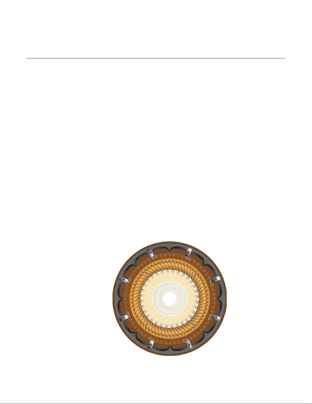
The Model 9139B Probe Card Adapter is an interface specifically designed to connect a Keithley
parametric test system to a device under test (DUT) while maintaining system specifications. It
provides greater accuracy of parametric tests in applications that require a wide range of
measurements, including high voltage up to 1.1 kV, while maintaining low-level measurement
performance. The high-capacity, low-leakage 9139B Probe Card Adapter allows you to make highvoltage measurements in multi-pin, fully automated production test applications.
Section 1
General information
Figure 1: 9139B probe card assembly
Page 9

Section
1: General information Model 9139B Probe Card Adapter
Instructions
Refer to the manufacturer documentation for your prober for information about connecting hardware
to it. Refer to the documentation provided with your Keithley parametric test system for information
about connections to the system.
Make sure you order the PCA with the correct stack height for your prober. Refer to probe card
adapter with and stack height (on page 6-2)
Features
Key features of the 9139B Probe Card Adapter include:
• Vacuum lock allows quick exchange of probe cards with accurate and repeatable alignment
• System supports up to 64 pins at up to 1.1 kV
• All pins use 1.1 kV triaxial connectors
• Optional hinged interface mechanism for easy probe card changes
• Easily connects device under test (DUT) cables to a probe card
• Each pin supports fully guarded measure and sense lines
• Maintains test system specifications to the probe tip
• Preserves full Kelvin connections to the probe tip
• Reduces capacitance with extended guards
• Extends low-current capabilities of the Keithley Parametric Test system
1-2 9139B-901-01 Rev. A / January 2019
Page 10
Model 9139B
Probe Card Adapter Instructions Section 1:
General information
Safety symbols and terms
Refer to Safety precautions (on page 1-1) for important information about safety symbols and all
precautions that must be taken when using the probe card adapter.
Hazardous voltages may be present on the probe card adapter, even after you disengage the
interlock. Cables can retain charges after the interlock is disengaged, exposing you to live
voltages that, if contacted, may cause personal injury or death.
Never attempt to touch or change a probe card when tests are running. You must be
absolutely certain that all tests have stopped before making contact with anything in the
vicinity of the probe card adapter. Also, never run tests without a probe card installed.
Related documentation
The following related customer documentation is included with the Keithley Parametric Test System:
• Administrative Guide (part number S530-924-01 and S535-924-01): This guide provides
information about Keithley Parametric Test Systems, including available configurations, sit
preparation and installation, equipment startup, connection diagrams, and maintenance.
• Reference Manual (part number S530-924-01 and S535-924-01): This manual describes how to
us
e the diagnostic and verification software suite that is part of your Keithley Parametric Test
System.
Unpacking and inspection
The following topics provide information about your shipment.
e
9139B-901-01 Rev. A / January 2019 1-3
Page 11
Section
1: General information Model 9139B Probe Card Adapter
Instructions
Handling precautions
The 9139B Probe Card Adapter is assembled at the factory to provide the highest quality connections
possible between the device under test (DUT) and your system. Use care when handling these parts.
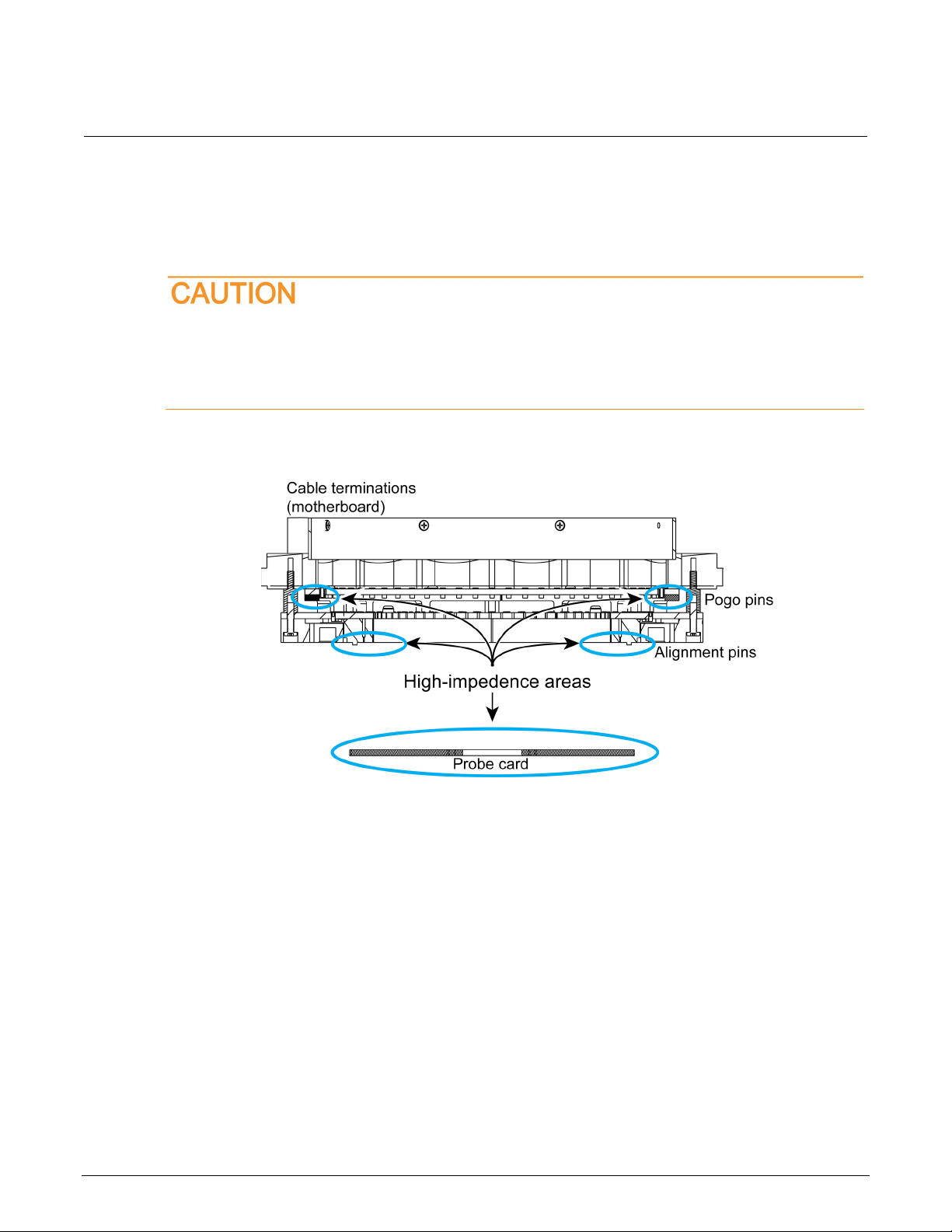
Do not touch high-impedance areas of the probe card assembly or the probe card. Touching
a high-impedance area will cause leakage and problems when performing low-current
measurements. Excessive leakage will cause the probe card adapter to fail system tests. See
the following figure for the location of high-impedance areas.
Figure 2: Handling 9139B
Take these precautions when handling the 9139B:
• Handle the board only by the edges.
• Use clean gloves to prevent inadvertent contact with high-impedance areas.
• Avoid bringing the board into contact with sources of contamination.
• Always confirm that fixtures and handling equipment are clean.
1-4 9139B-901-01 Rev. A / January 2019
Page 12

Model 9139B
Probe Card Adapter Instructions Section 1:
General information
Inspection for damage
Carefully unpack your 9139B Probe Card Adapter from its original shipping carton and inspect the
card for any obvious signs of physical damage. Report any such damage to the shipping agent
immediately. Save the original packing carton for possible future shipment.
Shipment contents
The following items are included with every 9139B:
• 9139B Probe Card Adapter
• Model 9139A-VUA vacuum control box
• Unpopulated (blank) probe card (this probe card is used for diagnostics and is installed in the
pr
obe card adapter)
• A shorted probe card for system verification
• 6 m (15 ft) of 0.64 cm (1/4 in.) vacuum hose
9139B-901-01 Rev. A / January 2019 1-5
Page 13

Page 14

Light cover ................................................................................2-5
Probe card adapter overview
In this section:
Probe card adapter standard components ................................2-1
Pin arrangement .......................................................................2-3
Leakage paths, low-current and high-voltage capabilities .........2-3
Motherboard characteristics ......................................................2-4
Probe card configuration ...........................................................2-4
Probe needle .............................................................................2-5
Probe card adapter standard components
The 9139B probe card adapter consists of the following components. See the drawing following this
list for details.
• Prober hardware
Section 2
• Probe card adapter assembly:
Appropriate device under test (DUT) cables
Strain reliefs and other miscellaneous hardware
Motherboard containing interconnect pins for DUT cable
connections
Pogo pins and retention ring
Light cover
Prober ring
Motherboard support plate
Insulation ring (Teflon®)
Probe card ring
Vacuum connection
Interlock switch cable assembly
Interlock magnet
• Probe cards (without probe pins)
One shorted probe card
One blank probe card
Page 15

Section
Instructions
1
Vacuum connection (not shown), PF-6
2
Wire guide quadrant HI, 386-8008-XX*, 4 places
3
Probe ring shield strap, 9139-314
4
Interlock light cover, S500-339
5
Interlock magnet, MA-4
6
Interlock switch, SW-498
7
Insulator, black decal, 9139-313-02
8
Probe ring shield plate, 9139-310
9
Probe ground ring, 389-5347
10
Probe ring insert, 9139A-325
11
9139B-PCA-02: ST-166-10 (3.378 cm, 1.330 in.)
13
Motherboard retainer ring, 9139A-326
14
Probe card, 389-5349-XX*
15
Alignment pins, spring contact retainer - probe card
16
Alignment pin, motherboard retainer - probe card retainer
17
Insulator (Teflon ring), 9139B-303
18
Probe card retainer cap, 9139B-301
19
Spring contact retainer, 9139B-302
2: Probe card adapter overview Model 9139B Probe Card Adapter
Figure 3: 9139B-PCA probe adapter components
Number Description
Spacer (sets stack height), 9139B-PCA-01: ST-166-9 (3.790 cm, 1.492 in.);
12 Probe ring motherboard, 389-5348-XX*
20 Shield strap mounting spacer, 386-8004-XX*
* XX represents the revision.
2-2 9139B-901-01 Rev. A / January 2019
Page 16

Model 9139B
rview
Probe Card Adapter Instructions Section 2: Probe card adapter ove
Pin arrangement
The 9139B Probe Card Adapter has 64 pins, each rated to 1100 V. All pins in the 9139B can
accommodate low-current signals.
The pins are arranged into symmetric sectors around a central point.
Figure 4: 9139B-PCA pin arrangement
Leakage paths, low-current and high-voltage capabilities
The 9139B Probe Card Adapter provides 1.1 kV capability to each of its 64 pins. It also significantly
improves low current leakage and settling time on each pin compared to the 9139A-PCA.
The 9139B Probe Card Adapter includes triaxial connectors that meet safety spacing requirements
and are compatible with existing triaxial mating connectors. This allows the included triaxial cables to
easily connect to the test hardware.
9139B-901-01 Rev. A / January 2019 2-3
Page 17

Section
Instructions
2: Probe card adapter overview Model 9139B Probe Card Adapter
Motherboard characteristics
The motherboard is the interface between the system and the probe card. It accepts up to 128
system cables (64 Kelvin pins) system cables and is suspended from the prober mounting hardware.
Source, sense, guard, and ground (where appropriate) are terminated for each DUT cable on the
motherboard.
Source, sense, and guard signals are kept separate for each pin and are carried to the probe card
through spring-loaded contacts (pogo pins). Source and measure lines are guarded on the
motherboard using printed circuit board manufacturing techniques.
System cables can be routed vertically or horizontally to the motherboard. Vertical routing is used
when the system cables are routed above the top platform (head plate) of the prober. Horizontal
routing is used when the system cables are routed under the top platform of the prober.
Probe card configuration
The probe card contains 64 fully guarded measure and sense lines. It contains mounting traces for 64
probe needles. Drilled, plated-through holes are provided for needle connection.
An unpopulated (blank) probe card is provided with the probe card adapter assembly. Additional
blank probe cards are available through your Keithley sales representative.
2-4 9139B-901-01 Rev. A / January 2019
Page 18

Model 9139B
obe card adapter overview
Probe Card Adapter Instructions Section 2: Pr
Probe needle
Ceramic needles are recommended; other types of needles (such as epoxy) may be used if they
conform to the dimensions in the following figure.
Figure 5: Probe needle mounting
Light cover
The light cover shields the opening in the center of the probe card adapter. This blocks ambient light
and permits testing under lights-out conditions.
Opening the light cover trips the safety interlock and interrupts testing.
9139B-901-01 Rev. A / January 2019 2-5
Page 19

Page 20

Optional top-load (clamshell) mechanism installation .............3-12
In this section:
Introduction ...............................................................................3-1
General installation considerations ...........................................3-1
Installation procedure ................................................................3-7
Probe card removal procedure ................................................3-10
Performance verification .........................................................3-10
Introduction
Section 3
Installation
The installation procedures contained in this manual are intended for use only by qualified
service personnel. Do not perform these procedures unless qualified to do so. Failure to
observe normal safety precautions could result in personal injury or death.
This section contains information needed to install the 9139B Probe Card Adapter on your prober.
Several topics contain general installation steps. Other topics contain installation steps required for
your specific prober. Review the appropriate topics before handling or installing the 9139B.
General installation considerations
The following topics provide information you should know before installing the 9139B Probe
Card Adapter.
Use of the 9139A prober card in the 9139B Probe Card Adapter will result in
diminished performance.
Do not use the 9139A probe card in testing that exceeds 200 V. Testing in excess of 200 V
may damage test equipment or cause injury or death due to electric shock.
Page 21

Section
Instructions
3: Installation Model 9139B Probe Card Adapter
Mechanical structure
The mechanical structure of the 9139B enables installation in a wide variety of probers. It consists of
a motherboard suspended from the prober ring. See the figure in
components (on page 2-1) for details.
Spacers inserted between the motherboard and prober ring connect the two assemblies. The length
of the spacers determines the overall stack height of the probe card assembly.
Safety
Failure to make sure that the safety interlock and safety shields and guards are properly
installed and arranged as indicated will put personnel in severe danger. Severe personal
injury or death due to electric shock or electrocution may result.
For the safety interlock to function properly, the device under test (DUT) interlock sensor
must be installed near the DUT connections and the interlock magnet must be installed on
the safety shield. It must be set up so that when the magnet is near the switch (interlock
closed) the operator cannot touch voltage-carrying conductors. If not properly installed, it will
render the interlock inoperative and place personnel at severe risk.
Probe card adapter standard
3-2 9139B-901-01 Rev. A / January 2019
Page 22

Model 9139B
Installation
Probe Card Adapter Instructions Section 3:
Keeping operators safe from hazardous voltages depends on proper installation. After installation, but
before energizing the unit, make sure all prober safety shields are properly in place. Refer to the
manufacturer of your specific prober for prober safety shield information.
The light cover contains components that allow installation of an interlock switch, such as that
provided with a Keithley S530 or S535 Parametric Test Systems, as shown in the following figure.
Figure 6: Probe card adapter light cover
Do not operate the system until it is properly installed and all prober safety shields are in
place. Failure to have the complete system properly installed with all safety shields in place
could result in personal injury or death.
9139B-901-01 Rev. A / January 2019 3-3
Page 23

Section
Instructions
3: Installation Model 9139B Probe Card Adapter
Additional probe card adapter safety interlock cable
The Model 174-7047-XX Safety Interlock Cable provides additional protection from electric shock at
the Keithley probe card adapter (PCA). The cable attaches to the prober top plate and the PCA so
that if you unlatch the top plate of the prober and lift it up to change a probe card or take off the PCA,
the interlock is tripped.
Figure 7: Model 174-7047-XX Safety Interlock Cable
The Model 174-7037-XX cable can be used with customer-supplied PCA solutions.
Figure 8: Model 174-7037-XX interlock cable
The Model 174-7047-XX cable interfaces with your prober interlock through a relay contact. A
shorted prober contact engages the interlock circuit. An open contact interrupts the interlock, turning
off hazardous voltage.
3-4 9139B-901-01 Rev. A / January 2019
Page 24

Model 9139B
Installation
Probe Card Adapter Instructions Section 3:
9139B Probe Card Adapter interlock schematic
The following diagram shows an example interlock configuration.
Figure 9: 9139B-PCA interlock block diagram
9139B-901-01 Rev. A / January 2019 3-5
Page 25

Section
Instructions
3: Installation Model 9139B Probe Card Adapter
Stack height
The height from the mounting seat of the prober to the surface of the chuck (stack height) is a basic
installation consideration.
Figure 10: 9139B-PCA
Stack height must be equal to the stack height of the probe card adapter. The stack height of the
Keithley probe card adapter can be 3.378 cm (1.330 in.) or 3.790 cm (1.492 in.), depending on the
type of prober and the requirements for cable routing.
Refer to Mechanical specifications (on page 6-1
determine if your prober is compatible. You may have to install mounting hardware onto the prober to
ensure that the prober stack height is the same as the probe card adapter stack height.
Cable routing
Cable routing is an important installation consideration. Device under test (DUT) cables can be routed
above or below the top plate of the prober. For cable routing above the top plate, the DUT cables exit
vertically from the probe card adapter. For cable routing below the top plate, the DUT cables exit
horizontally from the probe card adapter.
The DUT cables are routed under the prober ring of the probe card adapter and may exit from the left,
right, or back of the prober. The cable exit you use depends on the type of prober and how the prober
is oriented next to the system.
All DUT cables must be the same length. Uniform cable length provides uniform electrical
characteristics (capacitance and inductance) of the cables. This is important when performing
capacitance measurements or when measuring low-level currents.
) for detailed mechanical drawings of the 9139B to
See Installation procedure (on page 3-7
) for more information about installing DUT cables.
3-6 9139B-901-01 Rev. A / January 2019
Page 26

Model 9139B
Installation
Probe Card Adapter Instructions Section 3:
Light cover and microscope clearance
Check the light cover and microscope clearance. Most microscopes are located far enough above the
probe card assembly that they do not present clearance problems when the light cover is installed.
Some microscopes may protrude into the probe ring assembly to the area below the shield plate. This
presents clearance problems. If the microscope is mounted on a pivoted arm, move the microscope
aside and then install the light cover.
Installation procedure
Hazardous voltages may be present on an installed probe card even after the output is
disconnected, that if contacted, may cause personal injury or death.
To install the 9139B Probe Card Adapter:
You must supply all connections and hardware associated with vacuum hosing, in addition to the
vacuum source.
1. Unpack and inspect 9139B (see Handling precautions (on page 1-4) for special handling
information).
2. Remove all power from the parametric test system.
3. Install the probe card adapter in your prober, following the instructions provided with the prober.
The hardware supplied with your probe card adapter assembly varies depending on the type of
prober you have.
See Mechanical specifications (on page 6-1
) to determine if your prober is compatible. If you
need assistance with your specific prober configuration, contact your sales representative.
4. Route 0.635 cm (1/4 in.) outside diameter vacuum hose (provided) to the probe card adapter,
away from any moving parts of the prober. Make sure the hose remains clear of any pinch points
that could cut off or restrict flow through the vacuum hose.
5. Install the 9139B to a vacuum hose. Route a section of vacuum hose from the PCA through the
"TO PCA" grommet on the vacuum control box.
6. Connect the vacuum control box end of the hose to valve PF-1 (see the following figure) and the
other end of the hose to the PCA.
9139B-901-01 Rev. A / January 2019 3-7
Page 27

Section
Instructions
3: Installation Model 9139B Probe Card Adapter
Figure 11: Vacuum control box
3-8 9139B-901-01 Rev. A / January 2019
Page 28

Model 9139B
Installation
7. Install the vacuum supply hose. Route the vacuum supply hose from the vacuum source through
the "VACUUM IN" grommet on the vacuum control box.
8. Connect the vacuum control box end of the hose to check valve PF-5 (see the previous figure).
Make sure the vacuum supply is at least 50.80 cm (20 in.) Hg.
9. Vent the vacuum control box to atmosphere (no connection required).
10. Connect the PCA safety interlock cable to the prober top plate and the PCA.
11. Connect the device under test (DUT) cables between the probe card assembly and the matrix pin
cards of the parametric test system.
Route the cables to avoid sources of electromagnetic fields, vibration, or any other mechanical
disturbance.
12. Confirm that moving parts of the prober do not contact the cables.
Information about the location of connections within your system is in the configuration drawings
for your system. The user's manuals for the system contain additional information, if required.
Probe Card Adapter Instructions Section 3:
To install the probe card:
1. Turn the vacuum control box valve to the load/operate position.
2. Line up probe card pin 1 with the pin 1 indicator on the retainer cap (see the following figure).
Figure 12: Probe card and probe card retainer
3. Insert the probe card into probe card retainer cap.
Two alignment pins and holes are provided along the perimeter of the probe card. These holes and
pins allow proper orientation of the probe card during installation.
9139B-901-01 Rev. A / January 2019 3-9
Page 29

Section
Instructions
3: Installation Model 9139B Probe Card Adapter
4. Align pin 1 of the probe card with pin 1 of the motherboard. Use the alignment marking on
the edge of the probe card retainer cap and match to the same markings of the motherboard
support ring.
5. Attach the retainer cap to the motherboard ring. Make sure latches secure the probe ring (retainer
cap will click into place).
6. Use the system diagnostics tool to check Kelvin connections from the system matrix to the probe
card adapter.
Probe card removal procedure
Hazardous voltages may be present on an installed probe card even after the output is
disconnected, that if contacted, may cause personal injury or death.
Never attempt to touch or change a probe card when tests are running. You must be
absolutely certain that all tests have stopped before making contact with anything in the
vicinity of the probe card adapter. Also, never run tests without a probe card installed.
To remove the probe card:
1. Turn the vacuum control box valve to the unload position.
2. Release the probe card retainer cap latches.
3. Carefully remove the probe card and retainer cap from the probe card adapter.
3-10 9139B-901-01 Rev. A / January 2019
Page 30

Model 9139B
Installation
Probe Card Adapter Instructions Section 3:
Performance verification
A matrix test is run as part of system diagnostics and requires a blank (unpopulated) probe card. Run
a matrix test after the probe card adapter installation to check for leakage, open connections, or
shorted connections. Do not run a matrix test after installing each probe card.
During leakage tests, high voltages are present on the probe card adapter.
You must install a blank probe card in the probe card assembly to run diagnostics. A blank probe
card is supplied with the probe card adapter. You must keep this blank probe card.
The clean surface of the blank probe card provides a known, low-leakage test environment. The
unmodified Kelvin connections assure accurate continuity tests.
Handling and storage of the blank probe card is important (see Handling precautions (on page 1-4)).
For accurate leakage tests, follow these precautions:
• Do not populate the blank probe card; it must remain unpopulated.
• Store the blank probe card in a protective container in a clean, low-humidity environment.
• When installing the blank probe card, handle it by the edges; do not touch the surface of the
probe card.
For more information about running system verification and diagnostics, refer to the diagnostics and
verification manual for your system.
Performance verification using system diagnostics
Using the blank probe card provided with the 9139B, run the matrix test from the system diagnostics
tool on your Keithley parametric test system to verify probe card adapter performance.
For more information about the system diagnostics and verification tool, refer to the Diagnostics and
Verification Manual for your system.
9139B-901-01 Rev. A / January 2019 3-11
Page 31

Section
Instructions
3: Installation Model 9139B Probe Card Adapter
Optional top-load (clamshell) mechanism installation
The following instructions are for the top-load (clamshells) mechanism that are not ordered from
Keithley.
If present, remove the retainer clips and air fitting as shown in the following figure.
Figure 13: 9139B probe card adapter
Install the top-load mechanism as instructed by the manufacturer.
Verify that the interlock will trip when the top-load mechanism is opened. Failure to
make sure the interlock safety feature is functioning may cause injury or death due to
electrical shock.
3-12 9139B-901-01 Rev. A / January 2019
Page 32

Replacing the vacuum connection ............................................4-6
In this section:
Introduction ...............................................................................4-1
Mechanical disassembly ...........................................................4-2
Moving PCA cable connections ................................................4-3
Cleaning ....................................................................................4-3
Replacing a pogo pin ................................................................4-4
Replacing a pogo pin socket .....................................................4-5
Introduction
This section describes how to maintain and preserve the high-performance characteristics of the
probe card adapter.
Section 4
Maintenance
A minimum amount of maintenance is required for the motherboard and the device system cables.
However, when maintenance is required, it is important to perform maintenance operations correctly.
Maintenance tasks such as replacing cables can have a significant effect on the performance of the
probe card adapter.
When doing maintenance, lubricate all O-rings using VAC Goop® (from Swagelok®). Make sure to
use adequate VAC Goop for lubrication, but do not over-lubricate O-rings.
For maintenance of the probe pins, refer to documentation provided by the manufacturer of the
probe pins.
The system can source high voltages at current levels that can result in personal injury or
death. Turn off power to the system before performing any maintenance procedure.
Page 33

Section
4: Maintenance Model 9139B Probe Card Adapter
Instructions
Mechanical disassembly
Disassembly of the probe card adapter is required when replacing device under test (DUT) cables or
when motherboard maintenance is required.
When reassembling the probe card adapter, use VAC Goop® (from Swagelok®) to lubricate all
O-rings.
Hazardous voltages may be present on an installed probe card even after the output is
disconnected, that if contacted, may cause personal injury or death.
Never attempt to touch or change a probe card when tests are running. You must be
absolutely certain that all tests have stopped before making contact with anything in the
vicinity of the probe card adapter. Also, never run tests without a probe card installed.
If time and space are available, it is possible to disassemble the probe card adapter without
disconnecting the system cables.
To disassemble the probe card adapter:
1. Place the PCA in a safe state by resetting the test equipment.
2. Turn the vacuum control box valve to the unload position.
3. Disconnect the v
4. Disconnect the PCA cables from your system.
5. Disconnect the interlock cable from the probe card adapter.
6. Remove the probe card adapter assembly from your prober.
7. Remove the light cover assembly.
8. Remove the Allen screws that secure the cable strain relief for the cable being replaced
or moved.
9. Release the probe card retainer cap latches.
10. Carefully remove the probe card and retainer cap from the probe card adapter
acuum hose from the probe card adapter.
4-2 9139B-901-01 Rev. A / January 2019
Page 34

Model 9139B
Maintenance
Probe Card Adapter Instructions Section 4:
Moving PCA cable connections
Hazardous voltages may be present on an installed probe card even after the output is
disconnected, that if contacted, may cause personal injury or death.
Typically, prober pin 1 is connected to system pin 1, prober pin 2 is connected to system pin 2, and
so on. If an application requires different connections, you can connect the prober pins to other
system pins.
If you have an S530 or S535 parametric test system, each device under test (DUT) cable is
independently connected to the matrix. To move a PCA connection, unplug the DUT cable from
the matrix.
Cleaning
Cleaning is important to ensure accurate measurements. The cleaning process removes
contamination that causes shunt resistance (leakage) between measurement paths.
Contamination can take many forms. Some sources of contamination are:
• Residue remaining after incomplete cleaning
• Residue after using improper or contaminated cleaning fluids
• Residue from fingerprints (see Handling precautions (on page 1-4) for more information)
• Flux from soldering
• Condensation from room conditions that do not meet Keithley specifications
Observe the following precautions when it is necessary to use solder on a circuit board:
• Use lead-free solder, and take care not to spread the solder to other areas on the circuit board.
• Remove the solder from the work area when the repair has been completed. Use pure water and
clean foam-tipped swabs or a clean soft brush to remove the solder.
• Once the solder has been removed, swab only the repaired area with methanol, then blow-dry the
board with dry nitrogen gas.
9139B-901-01 Rev. A / January 2019 4-3
• After cleaning, allow the board to dry in a 50 °C low-humidity environment for several hours.
Page 35

Section
Instructions
4: Maintenance Model 9139B Probe Card Adapter
Replacing a pogo pin
Hazardous voltages may be present on an installed probe card even after the output is
disconnected, that if contacted, may cause personal injury or death.
To replace a pogo pin:
1. Reset the tester hardware.
2. Remove the probe card from the probe card adapter assembly (see
Probe card removal
procedure (on page 3-10)).
3. Using a pair of needle-nose pliers, pull the defective pogo pin out of its socket.
The pogo pins are not symmetrical. Damage to the socket may occur if the pogo pins are
inserted incorrectly.
4. Locate the rounded end of the replacement pogo pin (see the following figure).
Figure 14: Orientation of pogo pin and socket
5. Insert the rounded end of the pin into the socket. The double-chisel tip, on the other end of
the pogo pin, must protrude out of the socket. This end of the pogo pin contacts a pad on the
probe card.
6. Reinstall the probe card.
4-4 9139B-901-01 Rev. A / January 2019
Page 36

Model 9139B
Maintenance
Probe Card Adapter Instructions Section 4:
Replacing a pogo pin socket
If a pogo pin breaks off in a socket or if the pin becomes lodged in a socket, the pogo pin socket can
be replaced.
Hazardous voltages may be present on an installed probe card even after the output is
disconnected, that if contacted, may cause personal injury or death.
To replace a socket:
1. Follow the steps in Mechanical disassembly (on page 4-2
) to disassemble the probe
card adapter.
2. Locate the defective pogo pin or socket assembly.
3. Locate the pad where the defective socket is soldered to the motherboard. This pad is on the
probe-ring side of the motherboard (refer to the figure in
Probe card adapter standard
components (on page 2-1)).
4. Desolder the socket from the probe-ring side of the motherboard.
Do not apply excessive heat when desoldering the socket. Excessive heat can melt the
retention ring of the probe card adapter.
5. Push the end of the desoldered socket that protrudes through the motherboard and remove it by
pulling on the other side with a pair of needle-nose pliers.
6. Pull the socket out of its hole in the retention ring.
7. Remove residual solder from the hole of the solder pad.
8. Insert the small end of the replacement socket into the hole located in the retention ring (see the
figure in Replacing pogo pins (on page 4-4
)).
9. Slide the socket into the hole until the bottom of the socket is flush with the surface of the
retention ring (pogo pin not installed in the socket).
10. Confirm that the socket is installed properly (see the figure in Replacing pogo pins (on page 4-4
)).
The small end of the socket protrudes through the hole on the motherboard. The open end of the
socket is flush with the surface of the retainer ring.
11. Solder the socket to the pad located on the motherboard.
9139B-901-01 Rev. A / January 2019 4-5
Page 37

Section
Instructions
4: Maintenance Model 9139B Probe Card Adapter
12. Install a pogo pin in the socket.
13. Clean the flux from the solder connection (see Cleaning (on page 4-3
14. Reinstall the probe card.
Replacing the vacuum connection
The vacuum connection of the probe card adapter can be replaced if damaged.
To replace the vacuum connection:
1. Remove the vacuum connection.
2. Make sure all old sealant is removed from the threaded holes on probe card adapter.
3. Lightly apply standard pipe sealant to the new vacuum connection.
4. Install the new vacuum connection (do not over-tighten).
) for more information).
4-6 9139B-901-01 Rev. A / January 2019
Page 38

Parts list ....................................................................................5-1
In this section:
Ordering information .................................................................5-1
Factory service ..........................................................................5-1
Ordering information
To place an order or get information about replacement parts, contact your Keithley representative or
see the back cover of this manual for contact information. When ordering parts, be sure to include the
following information:
1. Probe card adapter model number: 9139B
Section 5
Replaceable parts
Factory service
2. Part description and part number
To return the probe card adapter to Keithley Instruments for repair:
1. Obtain a return authorization (RA) number from Keithley.
2. Carefully pack the probe card adapter in the original packing carton or the equivalent.
3. Ship it to the address provided by the customer service representative that provided your RA
number.
Parts list
This section contains a list of replaceable parts for the 9139B.
Blank probe card
For a replacement blank (unpopulated) probe card, order Keithley part number 389-5226-XX11.
1
Where XX represents the revision; the highest number is the most recent revision.
Page 39

Section
Instructions
0.025 pin
Wire guide quadrant HI (strain relief for high-voltage cables)
CS-835
386-8008-XX*
* XX represents the revision.
5: Replaceable parts Model 9139B Probe Card Adapter
9139B-01 and 9139B-02 parts list
The following table lists the replaceable parts for the 9139B-01 and 9139B-02 probe card adapters.
Description Keithley part number
4-40 × 1/4 Phillips pan-head screw (strap to mounting spacer)
4-40 × 3/8 socket button head (probe ring to spring contact retainer)
4-40 × 3/4 socket, button head (ring segment mounting)
6-32 × 3/4 Phillips pan-head screw (shield plate mounting)
6-32 × 1-1/4 socket, flat head (motherboard retainer mounting)
10 AWG PVC green/yellow
Cable assembly, interlock switch (single) includes interlock switch
Cable assembly, interlock switch (double) includes interlock switches
Cap, probe card retainer
Cover, interlock light
Handle, shield
Insulator (Teflon ring)
Insulator, black decal
Insulator, black decal
Interlock Magnet
Interlock switch (included in cable assembly)
Lug
Lug
Motherboard retainer ring
O-ring, thermobonded (use Swagelok
O-ring, thermobonded (use Swagelok VAC Goop)
Pin, crimp barrel, 0.040
Pin, crimp barrel, 0.060
Probe card
Probe card retainer cap
Probe ground ring
Probe, pogo pin
Probe ring insert
Probe ring shield
Probe ring shield strap
Probe ring, motherboard
Receptacle, pogo pin
Retainer, spring contact
Shield strap mounting spacer
Spring contact retainer
Socket, 0.025
Socket, 0.040
Socket, 0.060
Spacer 3.790 cm (1.492 in.) (9139B-PCA-01)
Spacer 3.378 cm (1.330 in.) (9139B-PCA-02)
Vacuum connection
Washer (motherboard to spring contact retainer)
®
VAC Goop®)
4-40X1/4PPH
4-40X3/8SOBTNH
4-40X3/4SOBTNH
6-32X3/4PPH
6-32X1-1/4SOFHS
SC-99-5
174-7037-XX*
174-7047-XX*
9139A-327
S500-339
HH-37
9139B-303
9139-313-01
9139-313-02
MA-4
SW-498
LU-99-6
LU-113
9139A-326
GA-32
GA-33
CS-836-1
CS-836-2
389-5349-XX*
9139B-301
389-5347-XX*
CS-830
9139A-325
9139-310
9139-314
389-5348-XX*
CS-831
9139A-331
386-8064-XX*
9139B-302
SO-146-1
SO-146-2
SO-146-3
ST-166-9
ST-166-10
PF-6
WA-102-2
5-2 9139B-901-01 Rev. A / January 2019
Page 40

Probe card adapter mechanical drawings .................................6-1
Mechanical specifications
In this section:
Probe card adapter mechanical drawings
You can use the drawings in this section to determine whether your prober is compatible with the
9139B.
Section 6
Probe card adapter assembly
Figure 15: Probe card adapter with probe card installed
Page 41

Section
Instructions
6: Mechanical specifications Model 9139B Probe Card Adapter
Probe card adapter width and stack height
Figure 16: Stack width and height
Probe card adapter top view pin arrangement
Figure 17: Pin arrangement
6-2 9139B-901-01 Rev. A / January 2019
Page 42

Model 9139B
Mechanical specifications
Probe Card Adapter Instructions Section 6:
Probe card dimensions
Figure 18: 9139B 1.1 kV 64-channel probe card dimensions
9139B-901-01 Rev. A / January 2019 6-3
Page 43

All Keithley trademarks and trade names are the property of Keithley Instruments.
All other trademarks and trade names are the property of their respective companies.
Specifications are subject to change without notice.
Corporate Headquarters • 28775 Aurora Road • Cleveland, Ohio 44139 • 440-248-0400 • Fax: 440-248-6168 • 1-800-935-5595 • www.tek.com/keithley
Keithley Instruments
12/17
 Loading...