

Page 1
Model 8010 High Power Device Test Fixture
Interconnection Reference Guide
Page 2

Safety precautions
The following safety precautions should be observed before using this product and any
associated instrumentation. Although some instruments and accessories would normally
be used with nonhazardous voltages, there are situations where hazardous conditions
may be present.
This product is intended for use by qualified personnel who recognize shock hazards
and are familiar with the safety precautions required to avoid possible injury. Read and
follow all installation, operation, and maintenance information carefully before using the
product. Refer to the user documentation for complete product specifications.
If the product is used in a manner not specified, the protection provided by the product
warranty may be impaired.
The types of product users are:
Responsible body is the individual or group responsible for the use and
maintenance of equipment, for ensuring that the equipment is operated within
its specifications and operating limits, and for ensuring that operators are
adequately trained.
Operators use the product for its intended function. They must be trained in
electrical safety procedures and proper use of the instrument. They must be
protected from electric shock and contact with hazardous live circuits.
Maintenance personnel perform routine procedures on the product to keep it
operating properly, for example, setting the line voltage or replacing
consumable materials. Maintenance procedures are described in the user
documentation. The procedures explicitly state if the operator may perform
them. Otherwise, they should be performed only by service personnel.
Service personnel are trained to work on live circuits, perform safe
installations, and repair products. Only properly trained service personnel may
perform installation and service procedures.
Keithley Instruments products are designed for use with electrical signals that are
measurement, control, and data I/O connections, with low transient overvoltages, and
must not be directly connected to mains voltage or to voltage sources with high
transient overvoltages. Measurement Category II (as referenced in IEC 60664)
connections require protection for high transient overvoltages often associated with
local AC mains connections. Certain Keithley measuring instruments may be connected
to mains. These instruments will be marked as category II or higher.
Unless explicitly allowed in the specifications, operating manual, and instrument labels,
do not connect any instrument to mains.
Exercise extreme caution when a shock hazard is present. Lethal voltage may be present
on cable connector jacks or test fixtures. The American National Standards Institute
(ANSI) states that a shock hazard exists when voltage levels greater than 30 V RMS,
42.4 V peak, or 60 VDC are present. A good safety practice is to expect that hazardous
voltage is present in any unknown circuit before measuring.
Operators of this product must be protected from electric shock at all times. The
responsible body must ensure that operators are prevented access and/or insulated from
every connection point. In some cases, connections must be exposed to potential
human contact. Product operators in these circumstances must be trained to protect
themselves from the risk of electric shock. If the circuit is capable of operating at or
above 1000 V, no conductive part of the circuit may be exposed.
Page 3
Do not connect switching cards directly to unlimited power circuits. They are intended
to be used with impedance-limited sources. NEVER connect switching cards directly to
AC mains. When connecting sources to switching cards, install protective devices to
limit fault current and voltage to the card.
Before operating an instrument, ensure that the line cord is connected to a properlygrounded power receptacle. Inspect the connecting cables, test leads, and jumpers for
possible wear, cracks, or breaks before each use.
When installing equipment where access to the main power cord is restricted, such as
rack mounting, a separate main input power disconnect device must be provided in
close proximity to the equipment and within easy reach of the operator.
For maximum safety, do not touch the product, test cables, or any other instruments
while power is applied to the circuit under test. ALWAYS remove power from the
entire test system and discharge any capacitors before: connecting or disconnecting
cables or jumpers, installing or removing switching cards, or making internal changes,
such as installing or removing jumpers.
Do not touch any object that could provide a current path to the common side of the
circuit under test or power line (earth) ground. Always make measurements with dry
hands while standing on a dry, insulated surface capable of withstanding the voltage
being measured.
When fuses are used in a product, replace with the same type and rating for continued
protection against fire hazard.
For safety, instruments and accessories must be used in accordance with the operating
instructions. If the instruments or accessories are used in a manner not specified in the
operating instructions, the protection provided by the equipment may be impaired.
Do not exceed the maximum signal levels of the instruments and accessories. Maximum
signal levels are defined in the specifications and operating information and shown on
the instrument panels, test fixture panels, and switching cards.
Chassis connections must only be used as shield connections for measuring circuits,
NOT as protective earth (safety ground) connections.
If you are using a test fixture, keep the lid closed while power is applied to the device
under test. Safe operation requires the use of a lid interlock.
If a screw is present, connect it to protective earth (safety ground) using the wire
recommended in the user documentation.
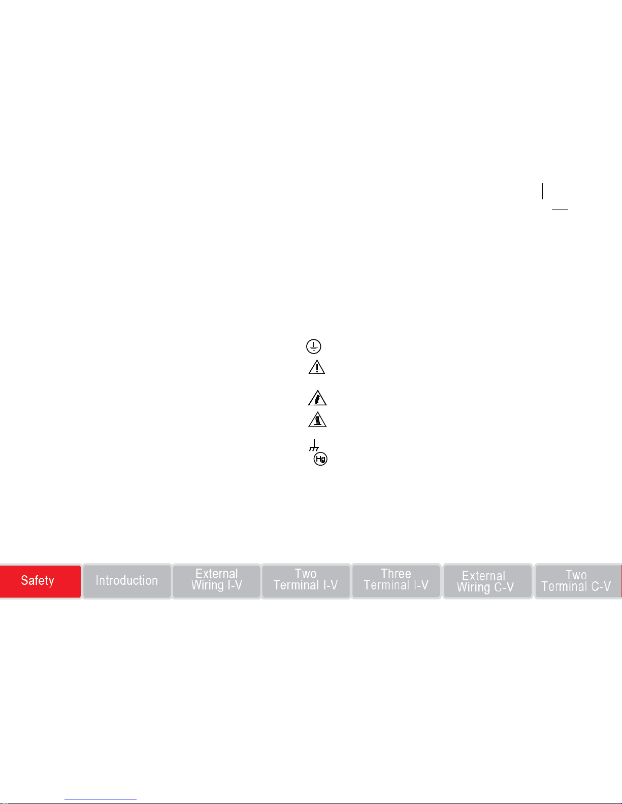
The symbol on an instrument means caution, risk of danger. The user must refer
to the operating instructions located in the user documentation in all cases where the
symbol is marked on the instrument.
The symbol on an instrument means caution, risk of electric shock. Use standard
safety precautions to avoid personal contact with these voltages.
The symbol on an instrument shows that the surface may be hot. Avoid personal
contact to prevent burns.
The
symbol indicates a connection terminal to the equipment frame.
If this symbol is on a product, it indicates that mercury is present in the display
lamp. Please note that the lamp must be properly disposed of according to federal, state,
and local laws.
The WARNING heading in the user documentation explains dangers that might result
in personal injury or death. Always read the associated information very carefully before
performing the indicated procedure.
The CAUTION heading in the user documentation explains hazards that could
damage the instrument. Such damage may invalidate the warranty
Page 4
Instrumentation and accessories shall not be connected to humans.
Before performing any maintenance, disconnect the line cord and all test cables.
To maintain protection from electric shock and fire, replacement components
in mains circuits — including the power transformer, test leads, and input jacks
— must be purchased from Keithley Instruments. Standard fuses with
applicable national safety approvals may be used if the rating and type are the
same. The detachable mains power cord provided with the instrument may only
be replaced with a similarly rated power cord. Other components that are not
safety-related may be purchased from other suppliers as long as they are
equivalent to the original component (note that selected parts should be
purchased only through Keithley Instruments to maintain accuracy and
functionality of the product). If you are unsure about the applicability of a
replacement component, call a Keithley Instruments office for information.
Unless otherwise noted in product-specific literature, Keithley instruments are
designed to operate indoors only, in the following environment: Altitude at or
below 2,000 m (6,562 ft); temperature 0 °C to 50 °C (32 °F to 122 °F); and
pollution degree 1 or 2.
To clean an instrument, use a damp cloth or mild, water-based cleaner. Clean
the exterior of the instrument only. Do not apply cleaner directly to the
instrument or allow liquids to enter or spill on the instrument. Products that
consist of a circuit board with no case or chassis (e.g., a data acquisition board
for installation into a computer) should never require cleaning if handled
according to instructions. If the board becomes contaminated and operation is
affected, the board should be returned to the factory for proper
cleaning/servicing.
Safety precaution revision as of March 2016.
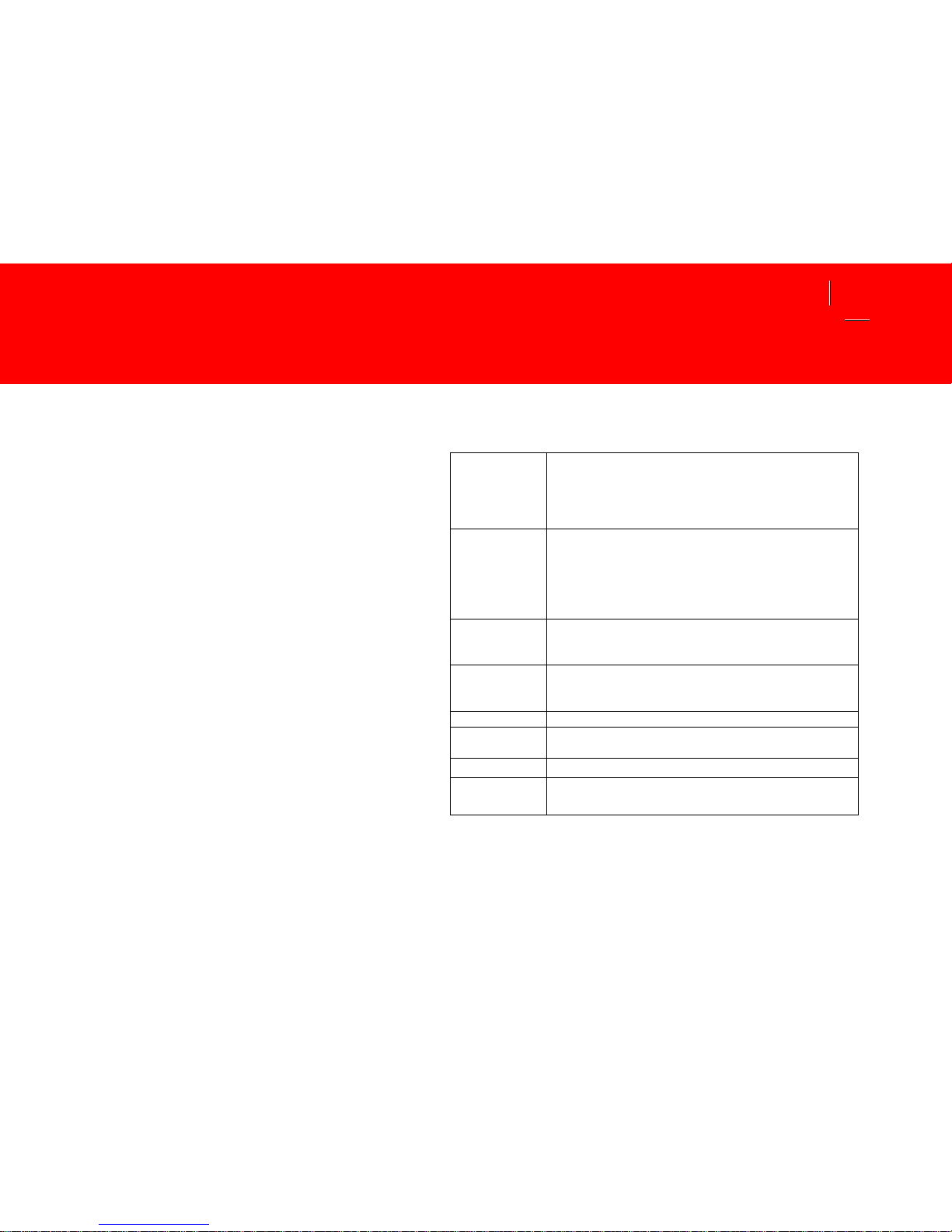
Power and environmental characteristics
For indoor use only.
Maximum
signal voltage
(signal or
guard to any
signal)
Three-lug hi gh -voltage triaxial connector: 3280 V
Three-lug st andard triaxial connector: 210 V
Eight-pin screw terminal connector: 40 V
Two-pin high-current screw ter m inal connec tor: 40 V
Maximum
signal curr ent
Three-lug hi gh -voltage triaxial connector: 120 mA DC
Three-lug st andard triaxial connect or: 1.5 A DC
Eight-pin screw terminal connector: 1 A DC
Two-pin high-current screw ter m inal connec tor: 15 A DC,
50 A pulsed with one SMU; 100 with two SMUs
Maximum
combined D C
current
15 A DC
Maximum
pulse current
100 A at 1 % dut y cycle for M odel 2651 High Po wer
SourceMeter Instrument path
10 A at 1 % duty cycle for Series 2600 and Model 4200 paths
Altitude
Maximum 20 00 m above sea level
Operating
0 °C to 50 °C, 70 % relative humidity up t o 35 °C
Derate 3 % relative humidity/°C, 35 °C to 50 °C
Storage
-25 °C to 65 °C
Safety
Listed to UL61010-1:2004
Conforms to European Uni on Low Voltage Directive
Page 5
Introduction to the Model 8010 test fixture
Thank you for choosing a Keithley Instruments product. The
Model 8010 provides a safe, low noise, complete environment for
testing a variety of packaged device types. The replaceable socket
modules allow for a variety of package types, including the
user-supplied socket types.
The Model 8010 allows you to connect one Model 2657 High Power
SourceMeter for up to 3000 V testing. You can connect up to two
Model 2651 High Power SourceMeters for 50 A or 100 A testing. For
lower power terminals, you can connect up to three other
SourceMeters (Models 2611, 2612, 2635, 2636, or 4200-SCS).
The Model 8010 documentation includes:
Interconnection Reference Guide: Provides a quick reference
for typical test connections and basic connection information.
User’s Manual: Provides complete connection information and
sample applications.
The User’s Manual is in PDF format and is on the CD-ROM that is
included with the test fixture. If you do not have Adobe Reader
®
,
you can download a free copy at http://get.adobe.com/reader/.
CD-ROM contents
The CD-ROM that is included with your test fixture contains the
following Model 8010 product documentation in PDF:
Interconnection Reference Guide (this document)
User’s Manual
Specifications
For additional information, see http://www.tek.com/support
.
Page 6

List of supplied accessories
In addition to the Model 8010 Test Fixture, you should have
received:
Model 8010 Interconnection Reference Guide (this document)
Model 8010 High Power Device Test Fixture Product
Information CD-ROM
Two pre-installed TO-247 device test boards (8010-120; to
reorder, use Keithley part number 8010-DTB)
Customizable test board (8010-130; to reorder, use Keithley part
number 8010-CTB)
Three 6.56 ft (2 m) interlock cables (CA-558-2)
Two 120 in. (304.6 cm) green/yellow ground cables with lugs
(CA-568-120)
Ten 8 in. (203.2 mm) black stack-up banana cables (CA-560-0)
Two 8 in. (203.2 mm) red stack-up banana cables (CA-560-2)
Ten insulating plugs (8010-317)
One 10 in. (254 mm) black high-current banana cable (CA-562-0)
One 10 in. (254 mm) red high-current banana cable (CA-562-2)
Six 9.5 in. (241 mm) low noise BNC-banana cable (CA-563)
Two document pouches (8010-318)
Optional and replacement boards that can be purchased are:
TO-247 device test board (8010-DTB) for use with
three-terminal TO-247 or two-terminal axial-lead devices at the
maximum rated voltage and current
8010-CTB customizable test board (8010-CTB) that you can
configure for the maximum rated voltage and current
TO-220 or TO-247 device test board (8010-DTB-220) for use
with three-terminal TO-220 or TO-247 devices that are limited to
1000 V and the maximum rated current
8010-DTB-CT device test board that you can use for curve
tracing.
Refer to the packing list for additional items that might have shipped
with your instrument.
For additional accessories, see the catalog, www.tek.com/keithley
, or
the CD-ROM.
Page 7
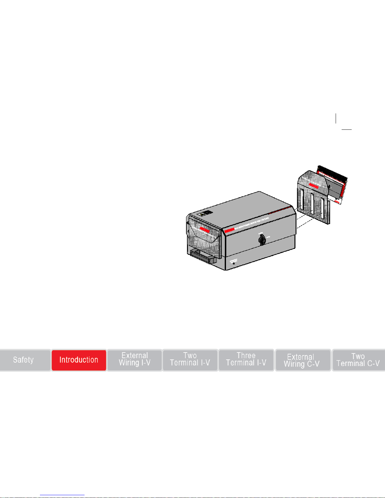
Attach pouches to the test fixture
Before installing the test fixture, attach the pouches (part number
8010-318) to the sides of the fixture, as shown here.
One pouch can be used to store the Interconnection Reference
Guide and the other can be used to store Model 8010 cables and
accessories.
To attach the pouches:
1. Make sure that the areas to which you want to attach the pouches
are clean. If you need to clean the test fixture, use a soft, lint-free
cloth and 70 percent isopropyl alcohol.
2. Close the lid of the test fixture.
3. Remove the protective backing from the hook and loop fastener
strips.
4. Position the pouch. Make sure placement of the pouch does not
interfere with the closing of the lid or your ability to use the
handles.
5. Press firmly.
8010 placement considerations
The Model 8010 is intended for use on a bench. Make sure you have
enough clearance to open the lid.
Page 8

Assumptions for connection diagrams
When you use the connection diagrams in this Interconnection
Reference Guide, be aware of the following assumptions.
SourceMeter® Instrument information
You cannot use a Model 2651 and Model 2657 simultaneously to test
a single device.
You can use a Model 2651 or Model 2657 simultaneously with a
Series 2600 instrument. When a Series 2600 is referenced in the
Model 8010 documentation, you can use any of the following
SourceMeter Instruments:
Model 2611
Model 2612
Model 2635
Model 2636
Using remote sense
If you are using remote sense connections, you must enable remote
sense on the instrument.
Types of devices
All three-terminal devices under test (DUTs) are assumed to be
MOSFETs. Therefore, the labels G-D-S on the connection diagrams
relate to the Gate, Drain, and Source of a MOSFET device.
If you are testing an insulated gate bipolar transistor (IGBT), make
the following substitutions:
G: Connect to the gate
D: Connect to the collector
S: Connect to the emitter
If you are testing a bipolar junction transistor, make the following
substitutions:
G: Connect to the base
D: Connect to the collector
S: Connect to the emitter
Note: Remove the 4200-PA Remote Preamplifier when the
4200-SCS is connected to the Model 8010 or to the CVU-3K-KIT
bias tees.
Page 9
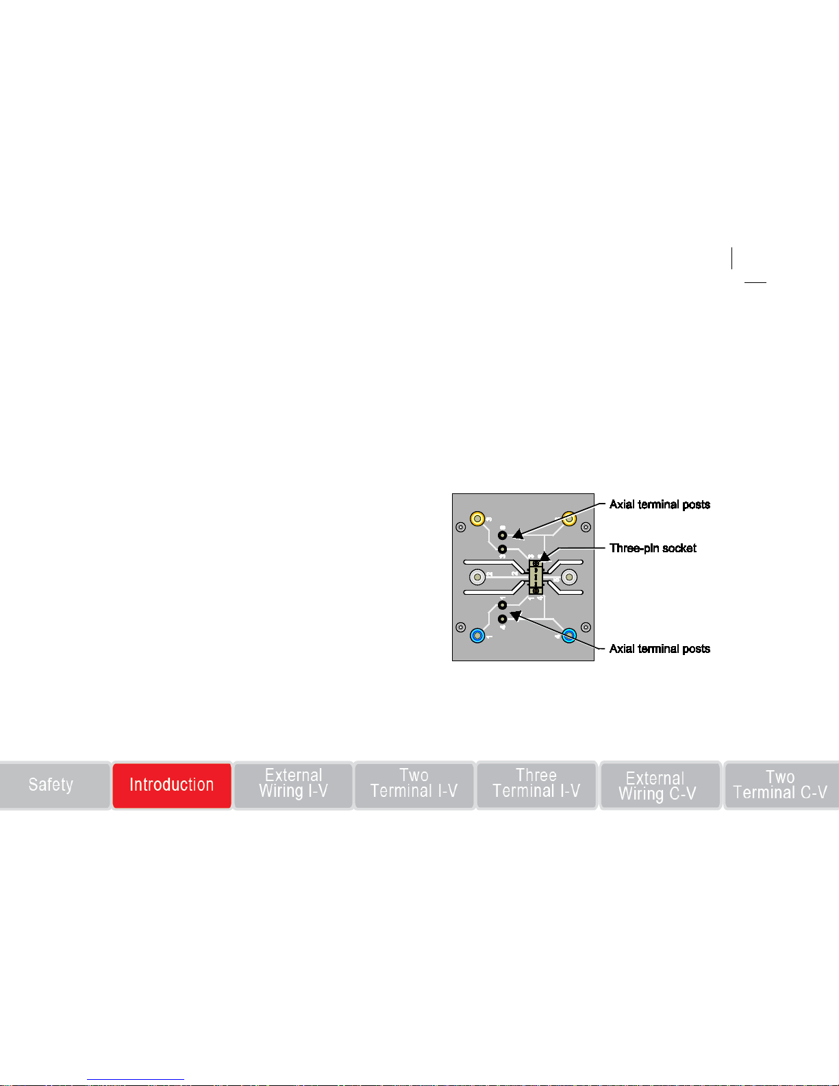
Insulating plug use
The Model 8010 comes with insulating plugs that can be used when
testing two-terminal devices.
The three-pin socket inherently shorts the force and sense pins
together. When you are using the axial terminal posts in 4-wire mode,
this can cause measurement errors. You should insert the insulating
plug into the three-pin socket when testing axial-lead devices in
4-wire sense mode where a short between force and sense will cause
measurement errors.
Do not use the insulating plug when testing higher resistance devices
(greater than 1 MΩ). Using the plug for these tests may cause leakage
measurement errors.
Testing two-terminal TO-247 devices
The two-terminal interconnection diagrams that are shown in this
document are intended for axial-lead devices. However, you can
adapt the setups so that you can test two-terminal TO-247 devices.
To test TO-247 devices, you need to:
1. Remove the insulating plug (if used) from the three-pin socket.
2. Verify that the four axial device terminal posts are not connected
to anything.
3. Place the two-terminal TO-247 device into the three-pin socket.
Page 10
Using both sides of the test fixture
In several of the interconnection diagrams, it is noted that you can
make equivalent connections on the other side of the test fixture. For
example, if you have an ongoing test using the Series 2600 connected
to the high-current side, you could set up a one-time test using the
equivalent terminals on the high-voltage side.
Note that this option is not available for test setups when you are
using a Model 2651 or Model 2657.
Do not simultaneously connect terminals in the high current and
high voltage areas of the fixture to the same terminals in the
center area (the area bordered in blue). S imultaneous
connections can result in electric shock (see previous graphic).
Page 11
Connect the test fixture external wiring (current-voltage)
Important test system safety information
This product is sold as a stand-alone test fixture that may become
part of a system that could contain hazardous voltages and energy
sources. It is the responsibility of the test system designer, integrator,
installer, maintenance personnel, and service personnel to make sure
that the system is safe during use and that it is operating properly.
It is important that you consider the following factors in your system
design and use:
The international safety standard UL 61010-1: 2004 defines
voltages as hazardous if they exceed 30 V RMS and 42.4 V peak,
or 60 V DC for equipment rated for dry locations. Keithley
Instruments products are only rated for dry locations.
Read and comply with the specifications of all instruments in the
system. The overall allowed signal levels may be constrained by
the lowest rated instrument in the system. For example, if you are
using a 500 V power supply with a 300 V DC rated switch, the
maximum allowed voltage in the system is 300 V DC.
Make sure any test fixture connected to the system protects the
operator from contact with hazardous voltages, hot surfaces, and
sharp objects. Use shields, barriers, insulation, and safety
interlocks to accomplish this.
Provide training to all system users so that they understand all
potential hazards and know how to protect themselves from
injury.
Never connect the guard t erminal from any instrument to the LO
terminal of any instrument in the Model 8010 or to the chassis.
Connecting guard to LO can disable the high voltage protection
that is installed across the Model 4200 or Model 2600
SourceMeter Instrument connections. This may result in
hazardous live voltages being present at the HI, SHI, SLO, or LO
terminals.
Page 12

Hazardous voltages may be pres ent on the output and guard
terminals. To prevent electrical shock that could cause injury or
death, NEVER make or break connections to the Model 8010
while the output from the SourceMeter Instrument (SMU) is on.
Turn off the instrument from the instrument front panel or
disconnect the main power cord f rom the rear of t he instrument
before handling cables connected to the outputs. Putting the
SMU into standby does not guarantee the outputs are not
powered if a hardware or software fault occurs.
Verify that all wiring is inside of the cross-hatched area of the
test fixture . Ensure that wi res do not protrude beyond the fixture
lid and that the lid will close securely. Exposed wire may result
in electric shock, causing death or serious injury.
The Model 8010 is provided with two protective earth (safety
ground) terminals on the rear panel. Ensure that both protective
earth terminals are properly connected to a known protective
earth before connecting instruments to the test fixture. Failure to
connect both protective earth terminals can result in electric
shock.
To keep users safe, always read and follow all
safety warnings provided with each of the
instruments in your system.
Page 13

External wiring diagram (current-voltage) measurement connections
Page 14

Two-terminal axial-lead DUT with a Model 2651 connected (local sense)
(lid open view of device test boards)
Page 15

Two-terminal axial-lead DUT with a Model 2651 connected (remote sense; current-voltage)
Note: You may need to add an insulating plug to prevent four-wire remote sense measurement errors. See Insulating plug use for detail.
Page 16

Two-terminal axial-lead DUT with a Model 2657 connected (local sense)
Page 17

Two-terminal axial-lead DUT with a Model 2657 connected (remote sense)
Note: You may need to add an insulating plug to prevent four-wire remote sense measurement errors. See Insulating plug use for detail.
Page 18

Two-terminal axial-lead DUT with a Series 2600 connected (local sense)
You can use equivalent connections for the high-current section (this option is not available for a Model 2651 or Model 2657 instrument).
Page 19

Two-terminal axial-lead DUT with a Series 2600 conn ect ed ( remote sense)
Notes: You may need to add an insulating plug to prevent four-wire remote sense measurement errors. See Insulating plug use for detail.
You can use equivalent connections for the high-current section (this option is not available for a Model 2651 or Model 2657 instrument).
Page 20

Two-terminal axial-lead DUT with a Model 4200-SMU connected (local sense)
Page 21

Two-terminal axial-lead DUT with a Model 4200-SMU connected (remote sense)
Notes: You may need to add an insulating plug to prevent four-wire remote sense measurement errors. See Insulating plug use for detail.
Page 22

This page intentionally left blank.
Page 23

Three-termin a l D UT with one or two Model 2651 instruments and Series 2600 instrument
connected (remote sense; current-voltage)
Note: Multiple Model 2651 instruments will be connected in parallel.
Page 24

Three-terminal DUT with a Model 2657 and a Series 2600 connected (local sense)
Page 25

Three-termin a l D UT with a Model 2657 and a Series 2600 connected (remote sense)
Page 26

Three-termin a l D UT with two Seri es 2600 instruments connected (local sense)
You can use equivalent connections for the high-current section (this option is not available for a Model 2651 or Model 2657 instrument).
Page 27

Three-termin a l D UT with two Series 2600 instruments connected (remote sense)
You can use equivalent connections for the high-current section (this option is not available for a Model 2651 or Model 2657 instrument).
Page 28

Three-terminal DUT with a 4200 and 2657 connected (lo cal sense)
Page 29

Three-terminal DUT with a 4200 and 2651 connect ed ( remote sense)
Page 30

Three-terminal DUT with a Model 4200-SMU con nected (remote sense)
Note: The SLO and LO terminals for all Model 42xx SMUs in a Model 4200-SCS chassis are joined in the 4200 GNDU.
Page 31

This page intentionally left blank.
Page 32

Page 33

Page 34

CVU-3K-KIT 2-terminal DUT (local sense)
Note that this configuration can be used for testing 2-terminal TO-247 devices, too. When testing 2-terminal TO-247 devices make sure to
remove the plug from the socket, if inserted; make sure the four axial device terminal posts are disconnected; place the 2-terminal TO-247
device into the 3-pin socket.
Page 35

CVU-200-KIT 2-terminal DUT (local sense)
Page 36

 Loading...