

Page 1

Model 7999-6GPIB RF Relay Unit
Instruction Manual
A GREATER MEASURE OF CONFIDENCE
Page 2

W ARRANTY
Keithley Instruments, Inc. warrants this product to be free from defects in material and workmanship for a
period of 1 year from date of shipment.
Keithley Instruments, Inc. warrants the following items for 90 days from the date of shipment: probes, cables,
rechargeable batteries, diskettes, and documentation.
During the warranty period, we will, at our option, either repair or replace any product that proves to be
defective.
To exercise this warranty, write or call your local Keithley representative, or contact Keithley headquarters in
Cleveland, Ohio. You will be given prompt assistance and return instructions. Send the product, transportation
prepaid, to the indicated service facility . Repairs will be made and the product returned, transportation prepaid.
Repaired or replaced products are warranted for the balance of the original warranty period, or at least 90 days.
LIMIT A TION OF W ARRANTY
This warranty does not apply to defects resulting from product modification without Keithley’s express written
consent, or misuse of any product or part. This warranty also does not apply to fuses, software, nonrechargeable batteries, damage from battery leakage, or problems arising from normal wear or failure to follow
instructions.
THIS WARRANTY IS IN LIEU OF ALL OTHER WARRANTIES, EXPRESSED OR IMPLIED, INCLUDING ANY IMPLIED WARRANTY OF MERCHANTABILITY OR FITNESS FOR A PARTICULAR USE.
THE REMEDIES PROVIDED HEREIN ARE BUYER’S SOLE AND EXCLUSIVE REMEDIES.
NEITHER KEITHLEY INSTRUMENTS, INC. NOR ANY OF ITS EMPLOYEES SHALL BE LIABLE FOR
ANY DIRECT , INDIRECT, SPECIAL, INCIDENTAL OR CONSEQUENTIAL DAMAGES ARISING OUT OF
THE USE OF ITS INSTRUMENTS AND SOFTWARE EVEN IF KEITHLEY INSTRUMENTS, INC., HAS
BEEN ADVISED IN ADVANCE OF THE POSSIBILITY OF SUCH DAMAGES. SUCH EXCLUDED DAMAGES SHALL INCLUDE, BUT ARE NOT LIMITED TO: COSTS OF REMOVAL AND INSTALLATION,
LOSSES SUSTAINED AS THE RESULT OF INJURY T O ANY PERSON, OR DAMAGE T O PROPER TY.
Keithley Instruments, Inc.
BELGIUM: Keithley Instruments B.V.
CHINA: Keithley Instruments China
FRANCE: Keithley Instruments Sarl
GERMANY: Keithley Instruments GmbH
GREAT BRITAIN: Keithley Instruments Ltd
INDIA: Keithley Instruments GmbH
ITALY: Keithley Instruments s.r.l.
NETHERLANDS: Keithley Instruments B.V.
SWITZERLAND: Keithley Instruments SA
TAIWAN: Keithley Instruments Taiwan
• 28775 Aurora Road • Cleveland, OH 44139 • 440-248-0400 • Fax: 440-248-6168 • http://www.k eithley.com
Bergensesteenweg 709 • B-1600 Sint-Pieters-Leeuw • 02/363 00 40 • Fax: 02/363 00 64
Y uan Chen Xin Building, Room 705 • 12 Y umin Road, De wai, Madian • Beijing 100029 • 8610-62022886 • Fax: 8610-62022892
3, allée des Garays • 91127 Palaiseau Cedex • 01-64 53 20 20 • Fax: 01-60 11 77 26
Landsberger Strasse 65 • 82110 Germering • 089/84 93 07-40 • Fax: 089/84 93 07-34
Unit 2 Commerce Park, Brunel Road • Theale • Reading • Berkshire RG7 4AB • 0118 929 7500 • Fax: 0118 929 7519
Flat 2B, WILOCRISSA • 14, Rest House Crescent • Bangalore 560 001 • 91-80-509-1320/21 • Fax: 91-80-509-1322
Viale S. Gimignano, 38 • 20146 Milano • 02-48 39 16 01 • Fax: 02-48 30 22 74
Postbus 559 • 4200 AN Gorinchem • 0183-635333 • Fax: 0183-630821
Kriesbachstrasse 4 • 8600 Dübendorf • 01-821 94 44 • Fax: 01-820 30 81
1 Fl. 85 Po Ai Street • Hsinchu, Taiwan, R.O.C. • 886-3572-9077 • Fax: 886-3572-903
4/01
Page 3

Model 7999-6 GPIB RF Relay Unit
Instruction Manual
©2001, Keithley Instruments, Inc.
All rights reserved.
Cleveland, Ohio, U.S.A.
First Printing, April 2001
Document Number: 7999-6-901-01 Rev. A
Page 4

Manual Print History
The print history shown below lists the printing dates of all Revisions and Addenda created
for this manual. The Revision Le vel letter increases alphabetically as the manual under goes subsequent updates. Addenda, which are released between Revisions, contain important change information that the user should incorporate immediately into the manual. Addenda are numbered
sequentially . When a new Re vision is created, all Addenda associated with the previous Re vision
of the manual are incorporated into the new Revision of the manual. Each ne w Revision includes
a revised copy of this print history page.
Revision A (Document Number 7999-6-901-01)............................................................ April 2001
All Keithley product names are trademarks or registered trademarks of Keithley Instruments, Inc.
Other brand names are trademarks or registered trademarks of their respective holders.
Page 5

Safety Precautions
The following safety precautions should be observed before using this product and any associated instrumentation. Although some instruments and accessories would normally be used with non-hazardous
voltages, there are situations where hazardous conditions may be present.
This product is intended for use by qualified personnel who recognize shock hazards and are familiar
with the safety precautions required to avoid possible injury. Read the operating information carefully
before using the product.
The types of product users are:
Responsible body
ensuring that the equipment is operated within its specifications and operating limits, and for ensuring
that operators are adequately trained.
Operators
and proper use of the instrument. They must be protected from electric shock and contact with hazardous
live circuits.
Maintenance personnel
setting the line voltage or replacing consumable materials. Maintenance procedures are described in the
manual. The procedures explicitly state if the operator may perform them. Otherwise, they should be
performed only by service personnel.
Service personnel
ucts. Only properly trained service personnel may perform installation and service procedures.
Keithley products are designed for use with electrical signals that are rated Installation Category I and
Installation Category II, as described in the International Electrotechnical Commission (IEC) Standard
IEC 60664. Most measurement, control, and data I/O signals are Installation Category I and must not
be directly connected to mains voltage or to voltage sources with high transient over-voltages. Installation Category II connections require protection for high transient over-v oltages often associated with local AC mains connections. The user should assume all measurement, control, and data I/O connections
are for connection to Category I sources unless otherwise marked or described in the Manual.
Exercise extreme caution when a shock hazard is present. Lethal voltage may be present on cable connector jacks or test fixtures. The American National Standards Institute (ANSI) states that a shock hazard exists when voltage lev els greater than 30V RMS, 42.4V peak, or 60VDC are present.
practice is to expect that hazardous voltage is present in any unknown circuit before measuring.
Users of this product must be protected from electric shock at all times. The responsible body must ensure that users are prevented access and/or insulated from every connection point. In some cases, connections must be exposed to potential human contact. Product users in these circumstances must be
trained to protect themselves from the risk of electric shock. If the circuit is capable of operating at or
above 1000 volts,
Do not connect switching cards directly to unlimited power circuits. They are intended to be used with
impedance limited sources. NEVER connect switching cards directly to AC mains. When connecting
sources to switching cards, install protective devices to limit fault current and voltage to the card.
Before operating an instrument, make sure the line cord is connected to a properly grounded power receptacle. Inspect the connecting cables, test leads, and jumpers for possible wear, cracks, or breaks before each use.
When installing equipment where access to the main power cord is restricted, such as rack mounting, a
separate main input power disconnect device must be provided, in close proximity to the equipment and
within easy reach of the operator.
is the individual or group responsible for the use and maintenance of equipment, for
use the product for its intended function. They must be trained in electrical safety procedures
are trained to work on live circuits, and perform safe installations and repairs of prod-
no conductive part of the circuit may be exposed.
perform routine procedures on the product to keep it operating, for example,
A good safety
Page 6

For maximum safety , do not touch the product, test cables, or an y other instruments while po wer is applied to
the circuit under test. ALWAYS remove power from the entire test system and discharge an y capacitors before:
connecting or disconnecting cables or jumpers, installing or removing switching cards, or making internal
changes, such as installing or removing jumpers.
Do not touch any object that could provide a current path to the common side of the circuit under test or power
line (earth) ground. Alw ays make measurements with dry hands while standing on a dry, insulated surface capable of withstanding the voltage being measured.
The instrument and accessories must be used in accordance with its specifications and operating instructions
or the safety of the equipment may be impaired.
Do not exceed the maximum signal levels of the instruments and accessories, as defined in the specifications
and operating information, and as shown on the instrument or test fixture panels, or switching card.
When fuses are used in a product, replace with same type and rating for continued protection against fire hazard.
Chassis connections must only be used as shield connections for measuring circuits, NOT as safety earth
ground connections.
If you are using a test fixture, keep the lid closed while power is applied to the device under test. Safe operation
requires the use of a lid interlock.
If a scre w is present, connect it to safety earth ground using the wire recommended in the user documentation.
!
The symbol on an instrument indicates that the user should refer to the operating instructions located in
the manual.
The symbol on an instrument shows that it can source or measure 1000 volts or more, including the combined effect of normal and common mode voltages. Use standard safety precautions to av oid personal contact
with these voltages.
The
WARNING
read the associated information very carefully before performing the indicated procedure.
CAUTION
The
invalidate the warranty.
Instrumentation and accessories shall not be connected to humans.
Before performing any maintenance, disconnect the line cord and all test cables.
To maintain protection from electric shock and fire, replacement components in mains circuits, including the
power transformer, test leads, and input jacks, must be purchased from Keithley Instruments. Standard fuses,
with applicable national safety approvals, may be used if the rating and type are the same. Other components
that are not safety related may be purchased from other suppliers as long as they are equivalent to the original
component. (Note that selected parts should be purchased only through Keithley Instruments to maintain accuracy and functionality of the product.) If you are unsure about the applicability of a replacement component,
call a Keithley Instruments office for information.
To clean an instrument, use a damp cloth or mild, water based cleaner. Clean the exterior of the instrument
only. Do not apply cleaner directly to the instrument or allow liquids to enter or spill on the instrument. Products that consist of a circuit board with no case or chassis (e.g., data acquisition board for installation into a
computer) should never require cleaning if handled according to instructions. If the board becomes contaminated and operation is affected, the board should be returned to the factory for proper cleaning/servicing.
heading in a manual explains dangers that might result in personal injury or death. Always
heading in a manual explains hazards that could damage the instrument. Such damage may
Rev. 2/01
Page 7
7999-6 GPIB RF Relay Unit
Relay Specifications
CONNECTOR TYPE:
Input: Female SMA connector (on relay).
Output: N-type.
CONTACT LIFE: 5 ×10
ACTUATION TIME: 15ms.
FREQUENCY RANGE: DC to 4GHz. Relay paths are 50Ω terminated
when open.
INSERTION LOSS: 0.3dB + 0.115
ISOLATION: 100dB minimum; 130dB typical.
SWR: 1.2 maximum.
INTERFACE: GPIB (IEEE-488.2) and SCPI.
INDICATORS: Power, relay position status and error LED.
CONTACT CLOSURE COUNTERS: One counter per relay path, up to
10 million counts each, maintained in non-volatile memory.
MAXIMUM COMMON MODE: 42V peak, any terminal to earth.
MAXIMUM SWITCHING SIGNAL: 1W CW, CAT I.
POWER: User-supplied 24VDC (22VDC min., 30VDC max.), 1.8A max.
ENVIRONMENT: Operating: 0° to 40°C, up to 35°C <80% RH.
EMC: Conforms with European Union Directive 89/336/EEC.
SAFETY: Conforms with European Union Directive 73/23/EEC.
DIMENSIONS: 429mm long × 133mm wide × 161mm deep (19.00˝ ×
5.25˝ × 6.34˝).
ACCESSORIES SUPPLIED: Instruction manual.
Specifications are subject to change without notice.
6
cycles minimum; 10 × 10
×
frequency (in GHz).
GENERAL
Storage: –25° to 65°C.
6
typical.
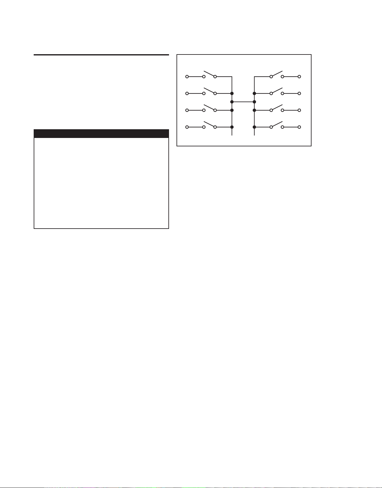
Simplified Schematic
SBG 4/9/01
Rev. A
Page 8

Page 9

T able of Contents
1 General Information
Introduction ................................................................................ 1-2
Feature overview ........................................................................ 1-2
Warranty information ................................................................. 1-2
Manual addenda ......................................................................... 1-2
Safety symbols and terms .......................................................... 1-3
Specifications ............................................................................. 1-3
Unpacking and inspection .......................................................... 1-3
Inspection for damage ......................................................... 1-3
Handling precautions .......................................................... 1-3
Shipment contents ............................................................... 1-4
Instruction manual .............................................................. 1-4
Repacking for shipment ...................................................... 1-4
Connections ................................................................................ 1-4
2 Connections
Introduction ................................................................................ 2-2
Handling precautions ................................................................. 2-2
Configuration ............................................................................. 2-2
Layout ................................................................................. 2-2
Simplified schematic ........................................................... 2-4
Connections ................................................................................ 2-5
GPIB control connection ..................................................... 2-5
Power connector .................................................................. 2-8
3 Operation
Introduction ................................................................................ 3-2
Maximum signal considerations ................................................ 3-2
Bus operation (GPIB) ................................................................. 3-3
Bus connections .................................................................. 3-3
Primary address ................................................................... 3-3
Programming syntax ........................................................... 3-3
Response messages ............................................................. 3-7
Status model ............................................................................... 3-8
Event register sets ............................................................. 3-10
Enable registers ................................................................. 3-11
Queues ............................................................................... 3-11
Status byte and SRQ ......................................................... 3-13
Service request enable register .......................................... 3-14
Serial polling and SRQ ..................................................... 3-15
Clearing registers and queues ................................................... 3-16
Page 10

Programming enable registers .................................................. 3-17
Reading registers ............................................................... 3-17
Common commands ................................................................. 3-18
GPIB commands ....................................................................... 3-26
ROUTe commands ............................................................ 3-26
:CLOSe............................................................................... 3-28
:CONFigure........................................................................ 3-29
STATus commands ............................................................ 3-30
:QUEue............................................................................... 3-30
SYSTem commands .......................................................... 3-32
Manual operation ...................................................................... 3-34
Switching considerations .......................................................... 3-35
Connector integrity ............................................................ 3-35
Voltage Standing Wave Ratio ............................................ 3-35
Path isolation ..................................................................... 3-36
Insertion loss ..................................................................... 3-36
RFI/EMI ............................................................................ 3-36
Errors ........................................................................................ 3-37
4 Service Information
Introduction ................................................................................ 4-2
Handling and cleaning precautions ............................................ 4-2
Handling precautions ........................................................... 4-2
Card and connector cleaning ............................................... 4-2
Performance verification ............................................................. 4-3
Environmental conditions .................................................... 4-3
Recommended equipment ................................................... 4-3
Channel resistance tests ....................................................... 4-3
Replacing components ................................................................ 4-4
Replacement parts ............................................................... 4-4
Replacement precautions ..................................................... 4-5
Soldering considerations ..................................................... 4-5
Relay replacement ............................................................... 4-5
Circuit board removal .......................................................... 4-8
GPIB address .............................................................................. 4-8
5 Replaceable Parts
Introduction ................................................................................ 5-2
Parts list ...................................................................................... 5-2
Ordering information .................................................................. 5-2
Factory service ............................................................................ 5-2
Component layout ...................................................................... 5-2
Page 11

List of Illustrations
2 Connections
Figure 2-1 General layout (front panel) ................................................... 2-3
Figure 2-2 General layout (rear panel) .................................................... 2-4
Figure 2-3 Simplified schematic .............................................................. 2-4
Figure 2-4 GPIB control connector ......................................................... 2-7
Figure 2-5 Power connector .................................................................... 2-8
3 Operation
Figure 3-1 Command diagram ................................................................. 3-5
Figure 3-2 Controlling relay connections ................................................ 3-6
Figure 3-3 Status model structure ........................................................... 3-9
Figure 3-4 Standard event status ............................................................ 3-10
Figure 3-5 Status byte and service request (SRQ) ................................. 3-13
Figure 3-6 16-bit status register ............................................................. 3-17
Figure 3-7 Standard event enable register ............................................. 3-20
Figure 3-8 Standard event status register ............................................... 3-21
Figure 3-9 Service request enable register ............................................ 3-23
Figure 3-10 Status byte register ............................................................... 3-25
Figure 3-11 Manual operation ................................................................. 3-34
4 Service Information
Figure 4-1 Channel resistance test connections ....................................... 4-4
Figure 4-2 Model 7999-6 exploded view ................................................ 4-6
Figure 4-3 GPIB address switch example ............................................... 4-9
Page 12

Page 13

List of T ables
2 Connections
Table 2-1 GPIB control connector terminals ......................................... 2-6
Table 2-2 Power connector pinouts ........................................................ 2-8
3 Operation
Table 3-1 Parameter types ...................................................................... 3-4
Table 3-2 SCPI commands — error queue .......................................... 3-12
Table 3-3 Common and SCPI commands — reset registers and
Table 3-4 IEEE-488.2 common commands and queries ...................... 3-18
Table 3-5 :ROUTe subsystem command set ........................................ 3-27
Table 3-6 :STATus subsystem command set ........................................ 3-30
Table 3-7 :SYSTem subsystem command set ...................................... 3-32
Table 3-8 Error and status message ...................................................... 3-37
4 Service Information
Table 4-1 Recommended verification equipment .................................. 4-3
5 Replaceable Parts
Table 5-1 Parts list—electronic components ......................................... 5-3
Table 5-2 Parts list—mechanical parts ................................................... 5-5
clear queues .................................................................... 3-16
Page 14

Page 15

1
General Information
Page 16

1-2 General Information
Introduction
This section contains general information about the Model 7999-6 GPIB RF Relay. The
information is organized as follows:
• Feature overview
• Warranty information
• Manual addenda
• Safety symbols and terms
• Specifications
• Unpacking and inspection
• Connections
If you have any questions after reviewing this information, please contact your local
Keithley representative or call one of our Applications Engineers at 1-800-KEITHLEY.
Worldwide phone numbers are listed at the front of this manual.
Feature overview
The Model 7999-6 is an IEEE-488 controlled, single or dual, 4 or 6 pole, 19-inch rack
mounted relay unit. Additional features of the Model 7999-6 are as follows:
• N-type bulkhead connectors (insulated)
• +24VDC power connections
• LED indicators for error, power, and relay status
• Operating range to 4GHz (relay dependent)
• Can be upgraded from 4-pole to 6-pole relays
W arranty information
Warranty information is located at the front of this instruction manual. Should your Model
7999-6 require warranty service, contact the Keithley representative or authorized repair facility in your area for further information. When returning the Model 7999-6 for repair, be sure to
fill out and include the service form at the back of this manual to provide the repair facility with
the necessary information.
Manual addenda
Any improvements or changes concerning the Model 7999-6 or manual will be explained in
an addendum included with the manual. Be sure to note these changes and incorporate them
into the manual.
Page 17

Safety symbols and terms
The following symbols and terms may be found on the Model 7999-6 or used in this manual.
The symbol indicates that the user should refer to the operating instructions
!
located in the manual.
The
symbol
dard safety precautions to avoid personal contact with these voltages.
The
WARNING
injury or death. Always read the associated information very carefully before performing the
indicated procedure.
The
CAUTION
Such damage may invalidate the warranty.
shows that high voltage may be present on the terminal(s). Use stan-
heading used in this manual explains dangers that might result in personal
heading used in this manual explains hazards that could damage the switch.
Specifications
Full Model 7999-6 specifications are included at the front of this manual.
General Information 1-3
Unpacking and inspection
Inspection for damage
The Model 7999-6 is packaged in a re-sealable, anti-static bag to protect it from damage due
to static discharge and from contamination that could degrade its performance. Before removing the Model 7999-6 from the bag, observe the precautions on handling discussed below.
Handling precautions
• Always grasp the Model 7999-6 by the covers. Do not touch board surfaces or
components.
• After removing the Model 7999-6 from its anti-static bag, inspect it for any obvious
signs of physical damage. Report any such damage to the shipping agent immediately.
• When the Model 7999-6 is not installed and connected, keep the unit in its anti-static
bag and store it in the original packing carton.
Page 18

1-4 General Information
Shipment contents
The following items are included with every Model 7999-6 order:
• Model 7999-6 GPIB Relay Unit (single or dual 4-pole/6-pole IEEE-488 controlled
relay switch)
• Model 7999-6 Instruction Manual (this manual)
• Additional accessories as ordered
Instruction manual
If an additional Model 7999-6 Instruction Manual is required, order the manual package,
Keithley part number 7999-6-901-00. The manual package includes an instruction manual and
any pertinent addenda.
Repacking for shipment
Should it become necessary to return the Model 7999-6 for repair, carefully pack the unit in
its original packing carton or the equivalent, and follow these instructions:
• Call the Repair Department at 1-800-552-1115 for a Return Material Authorization
(RMA) number.
• Advise as to the warranty status of the Model 7999-6.
• Write ATTENTION REPAIR DEPARTMENT and the RMA number on the shipping
label.
• Fill out and include the Service Form located at the back of this manual.
Connections
The following are available Model 7999-6 connections:
• Power receptacle: 9-pin D-sub connector
• IEEE-488 port (GPIB connector)
• N-type bulkhead connectors
NOTE
Refer to Section 2 for detailed connection information.
Page 19

2
Connections
Page 20

2-2 Connections
Introduction
This section contains information about overall switch configuration and connections and is
organized as follows:
• Handling precautions
• Configuration
• Connections
WARNING
The procedures in this section are intended only for qualified service personnel. Do not perform these procedures unless you are qualified to do so.
Failure to recognize and observe normal safety precautions could result in
personal injury or death.
Handling precautions
To maintain high-impedance isolation, care should be taken when handling the switch to
avoid contamination from foreign materials such as body oils. Such contamination can reduce
isolation resistance. To avoid possible contamination:
• Always grasp the switch by the handles or the relay housing.
• Do not touch bulkhead connector insulators.
• Operate the switch in a clean environment. If the switch becomes contaminated, it
should be thoroughly cleaned as explained in Section 4.
Configuration
Layout
Figure 2-1 and Figure 2-2 show the general layout of the Model 7999-6 featuring the
following:
Connectors:
• Power receptacle (9-pin male D-sub connector)
• GPIB Control: IEEE-488 interface connector
• N-type insulated bulkhead input connectors
Indicators:
• Power LED
• ERR LED (communication error or failed power on self-test)
• Relay state LEDs (one for each relay pole)
Switches:
• Manual toggle switch (one per relay)
Page 21

Figure 2-1
X225
X201
2
General layout (front panel)
7999-6 GPIB RF RELAY UNIT
OPEN
ALL
1
STEP POS.
RELAY 1
2
(1-6)
3
4
X225 X201 X202 X226 X203
Connections 2-3
5
6
PWRERR
MS CODE: 00309
1
3
4
5
6
OPEN
ALL
STEP POS.
(1-6)
OPEN
ALL
STEP POS.
X204
(1-6)
X225 X203
RELAY 1
1
2
3
4
5
6
PWRERR
X201
Relay 1 Manual
toggle switch
Relay 1 state LEDs
Power LED
ERR LED
RELAY 2
1
2
3
4
Relay 2 state LEDs
5
6
OPEN
ALL
STEP POS.
(1-6)
Relay 2 Manual
toggle switch
Output
connectors
Input connectors
(N-type, insulated
from chassis)
Page 22
2-4 Connections
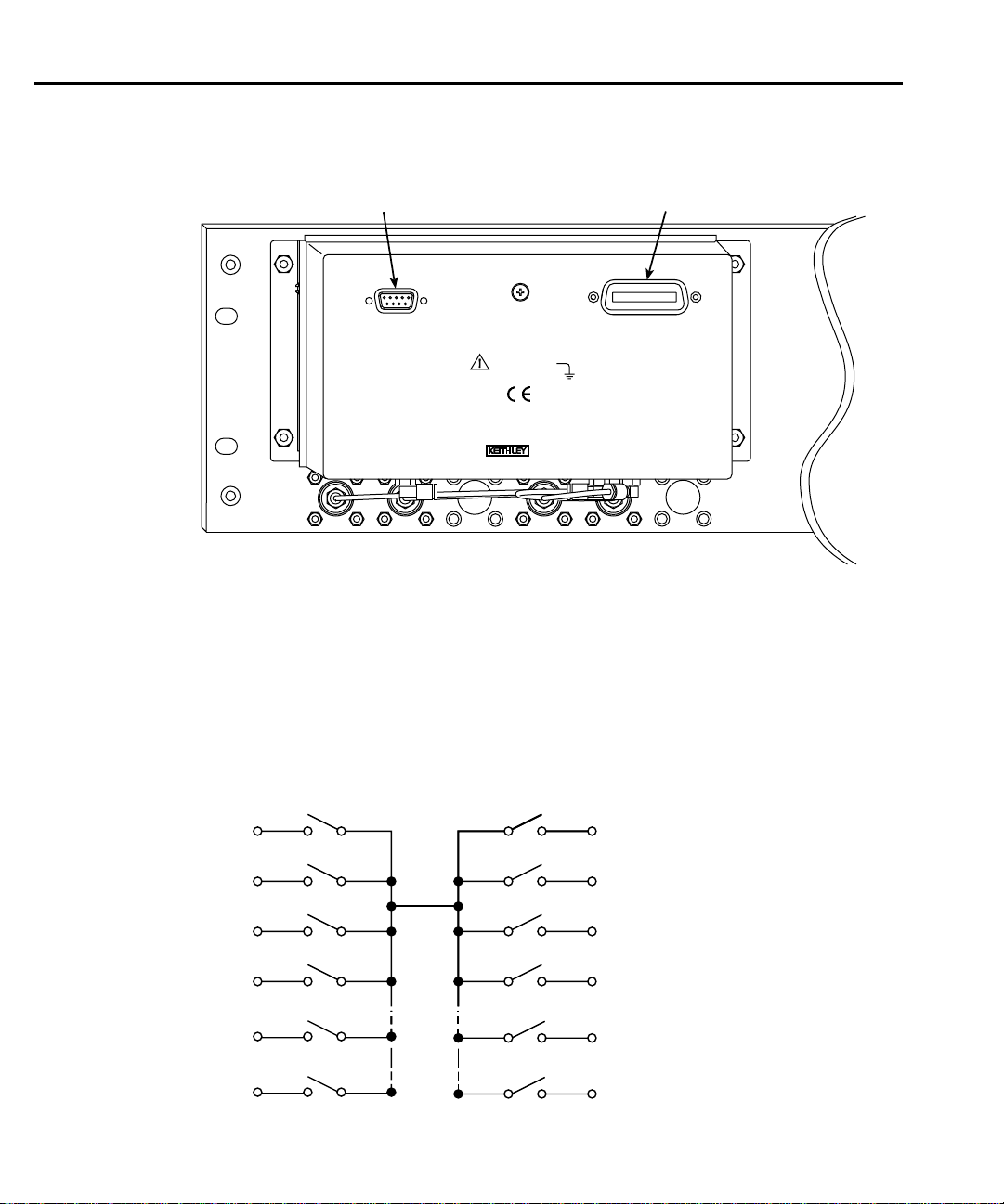
Figure 2-2
General layout (rear panel)
Power connector GPIB connector
Simplified schematic
Figure 2-3 shows a simplified schematic diagram of the Model 7999-6. The solid lines rep-
resent a 4-pole relay; the additional dashed lines represent a 6-pole relay.
Figure 2-3
Simplified schematic
Output
Connections
2
INPUT POWER
(24 VDC)
CATI
WARNING
NO INTERNAL OPERATOR
SERVICABLE PARTS, SERVICE
BY QUALIFIED PERSONNEL ONLY.
42V MAX.
ANY CONDUCTOR
MS CODE: 00313
MADE IN
(SET IEEE ADDRESS INTERNALLY)
U.S.A
RELAY #1RELAY #2
IEEE-488
X201
3
5
6
1
4
X202
X203
X204
X225
X226
Page 23

Connections
GPIB control connection
The GPIB control port is connected to the GPIB port of a computer (controller) using a
shielded IEEE-488 interface cable with metric mating screws.
Remember the following restrictions when attaching instruments to the GPIB:
If you cannot meet these requirements, the use of bus extenders is recommended.
Connections 2-5
– A maximum separation of 4 meters between any two instruments on the bus.
– A maximum total cable length of 20 meters.
– No more than 15 devices on the bus.
– No two instruments having the same address.
CAUTION
Connectors may be stacked to allow a number of parallel connections to one instrument.
Two screws located on a standard connector maintain secure connections between connectors.
NOTE
Connect devices to the GPIB as follows:
1. Line up the cable connector with the connector located on the Model 7999-6. The connector’s design allows installation to the port in only one position.
2. Secure connector by tightening screws firmly (do not overtighten).
3. Add any additional connectors to the port as required.
4. Connect the free end of the cable to the controller.
5. Check that the GPIB address and other GPIB protocol information is properly set. (See
Section 4 of this manual for GPIB address information.)
IEEE-488 common is connected to digital common. Maximum voltage
between digital common and earth ground is 0V.
To minimize interference caused by electromagnetic radiation, use shielded
IEEE-488 cables.
Page 24

2-6 Connections
Table 2-1
GPIB control connector terminals
* Numbers in parentheses refer to signal ground return of referenced contact
Contact
Number IEEE-488 designation Type
01 DI01 Data
02 DI02 Data
03 DI03 Data
04 DI04 Data
05 EOI (24)* Management
06 DAV Handshake
07 NRFD Handshake
08 NDAC Handshake
09 IFC Management
10 SRQ Management
11 ATN Management
12 SHIELD Ground
13 DI05 Data
14 DI06 Data
15 DI07 Data
16 DI08 Data
17 REN (24)* Management
18 Gnd (6) * Ground
19 Gnd (7) * Ground
20 Gnd (8) * Ground
21 Gnd (9) * Ground
22 Gnd (10) * Ground
23 Gnd (11) * Ground
24 Gnd, LOGIC Ground
number. EOI and REN signal lines return on contact 24.
Page 25

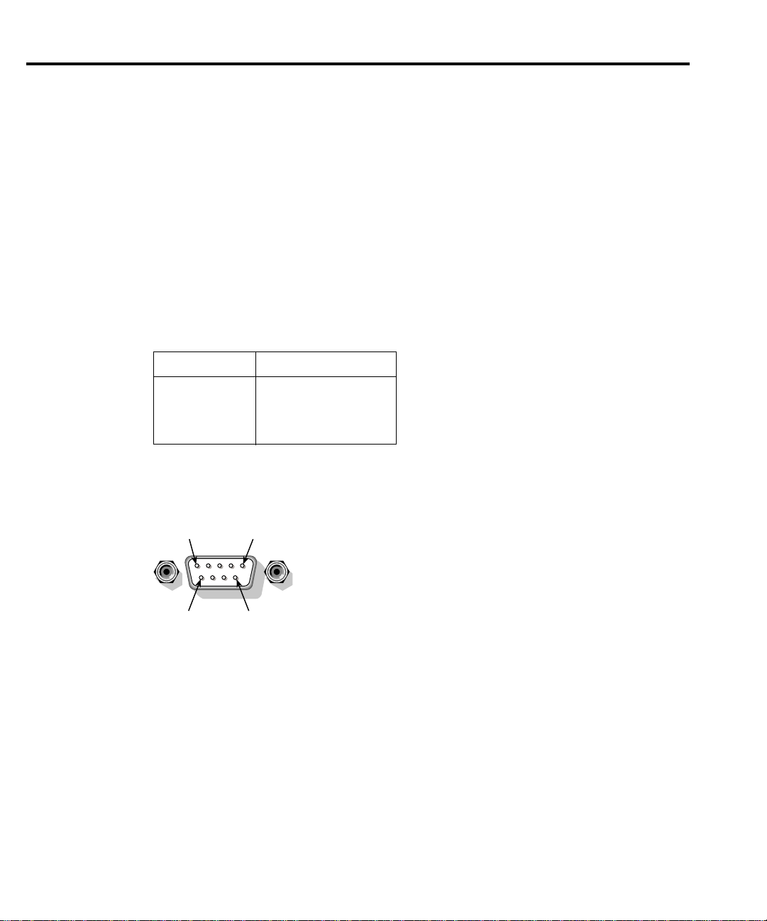
Figure 2-4
GPIB control connector
Connections 2-7
12
24
1
13
GPIB address
On the main circuit board, there are five GPIB address DIP switches. When shipped from
the factory, the GPIB address is set to 3. To change the GPIB address of the relay, refer to
Section 4 of this manual.
Page 26
2-8 Connections
Power connector
properly wired (UL listed cable with a 9-PIN D-subminiature female connector—the Model
7999-6 power connector’s pinouts are shown in Figure 2-5 with the pin descriptions contained
in Table 2-2).
Connect the 24VDC power supply to the power connector. Make sure the power supply is
WARNING
Table 2-2
Power connector pinouts
Pin Number Description
1, 2 Positive (+)
4, 5 Negative (-)
6, 7, 8, 9 (Not used)
Figure 2-5
Power connector
Pin 1
Pin 6 Pin 9
To prevent damage to the Model 7999-6 and to prevent the risk of electric
shock, use only a properly rated power supply. The power supply must be
double insulated, have the required safety agency approvals for the low
voltage directives, EMC directives, and CE certification. It must also provide output current limiting and short-circuit protection.
3 (Not used)
Pin 5
Page 27

3
Operation
Page 28

3-2 Operation
Introduction
This section contains the following operating information for the Model 7999-6:
• “Maximum signal considerations” on page 3-2
• “Bus operation (GPIB)” on page 3-3
• “Status model” on page 3-8
• “Programming enable registers” on page 3-17
• “Common commands” on page 3-18
• “GPIB commands” on page 3-26
• “Manual operation” on page 3-34
• “Switching considerations” on page 3-35
• “Errors” on page 3-37
Maximum signal considerations
WARNING
CAUTION
• Maximum Voltage: 30VDC, 42V peak
• Maximum Switching Signal: 1W CW, CAT I
Maximum voltage between any conductor and ground is 42V.
T o prevent damage to the Model 7999-6, do not exceed the following maximum signal level specifications of the switch:
Page 29

Bus operation (GPIB)
Operation 3-3
NOTE
The term GPIB (General Purpose Bus Interface) is used in this manual. GPIB is
simply another term for the IEEE-488 bus.
Bus connections
Before using the switch, you must connect the IEEE-488 connector on the rear panel of the
switch to the IEEE-488 connector of the controller. Use a Keithley Model 7077 or similar
shielded IEEE-488 cable for this connection. Refer to Section 2 for more information on the
IEEE-488 connection.
Primary address
The primary address of the Model 7999-6 must agree with the primary address you intend to
specify in the controller’s programming language. On the main circuit board, there are five
GPIB address DIP switches. When shipped from the factory, the GPIB address is set to 3. To
change the GPIB address of the relay, refer to Section 4 of this manual.
Programming syntax
Syntax rules for programming the Model 7999-6 are covered in this paragraph.
Commands and parameters
The general form for SCPI commands is demonstrated in Tables 3-2 through 3-4. They are
hierarchical in nature and begin with a root command. For example, to open all channels for
relays 1 and 2, send the following command:
:OPEN:ALL
The root path command for the above example is ROUTe. This is an optional command
word (as indicated by the brackets ([ ]) in the table) and need not be used.
The general form for Common Commands is shown in Table 3-4.
NOTE
Each common command is preceded by a star (*).
Page 30

3-4 Operation
Parameters provide specific types of information. The following list (Table 3-1) contains the
definitions of the different parameter types.
Table 3-1
Parameter types
Parameter Description
<name> Name parameter: Select a parameter name from a listed group.
<clist> List of channels. The following examples demonstrate proper format:
(@1!1,1!5) Channels 1 and 5 of relay 1
<b> Boolean: Enable (1 or on) or disable (0 or off) a function.
<NRf> Numeric representation format: Number can be expressed as an integer ,
real number or an exponent (e.g. 2.3E6).
<n> Numeric value: An NRf number or one of the following name
parameters:
-DEFault: Uses the *RST default parameter value
-MINimum: Uses the lowest allowable parameter value
-MAXimum: Uses the largest allowable parameter value
Short-form commands
Most SCPI command words and name parameters have a short-form version. The short-
form versions are identified in the SCPI tables by the upper case characters. Example:
:ROUT:CLOS (@1!2,2!4) = :ROUTe:CLOSe (@1!2,2!4)
NOTE
Command words and parameter names are not case sensitive.
Query commands
Query commands request information (queries) and can be identified by the question mark
appearing after the command (?). Example:
:CLOSe?
Queries the channels that are closed.
Command messages
Program Message — A program message is made up of one or more command words sent
by the computer to the instrument. Some programming operations require several command
words.
Single Command Message — This program message uses the command words required to
perform a single programming operation. Example:
:SYST:ERR?
Reads the system error queue.
Page 31

Operation 3-5
Multiple Command Message — This program message contains two or more command
operations. Each command string is separated by a semicolon (;). The following example uses
the short-form format to reduce the size of the message:
:ROUT:CLOS (@1!2,2!4);:ROUT:CLOS?
The above program message closes 1!2 and 2!4, and then queries for closed relays.
Commands that are on the same command level can be executed without having to repeat
the entire command path. For example:
:ROUT:CONF:CPOL1 4;CPOL2 4
Since :CPOL1 and :CPOL2 are on the same command level (see ), the :ROUT:CONF command word does not have to be repeated for the second command string. Note also that the
leading colon (:) for :CPOL2? is not used. Common commands and SCPI commands can be
used in the same program message as long as they are separated by a semicolon (;). Example:
*RST;CLOSe (@1!1,l!3)
Example command
To connect the N-connector X201 to output 5 of relay 1, send:
:ROUT:CLOS (@2!2,1!5);
Refer to Figure 3-1 for a diagram of the parts of this command and to Figure 3-2 for an illustration of the physical connections.
Figure 3-1
Command diagram
Command
Root path
Relay number
:ROUT:CLOS (@2!2,1!4);
Channel number
Page 32

3-6 Operation
Figure 3-2
Controlling relay connections
OPEN
ALL
STEP POS.
RELAY 1
1
(1-6)
2
3
4
5
6
X225 X203
X201
PWRERR
RELAY 2
1
2
3
4
5
6
OPEN
ALL
STEP POS.
(1-6)
NOTE
4-pole relay shown.
Dashed lines designate
additional paths for
6-pole relay.
N-type bulkhead
connectors
Input
1!5
1!6
1!1
2!1 2!4
2!2 2!3 2!5 2!6
X225 X201 X202 X226 X203
5
4
3
6
1
1
2
X204
2
3
4
6
5
1!4
1!2
1!3
Relay 1
Output
Relay 2
Input
The Model 7999-6 contains two relays that are IEEE controlled and connected center-tocenter with blocking. The signal is brought in through one of four bulkhead connections and
switched to one of four output connections (switching is controlled over the IEEE bus). In our
example, relays 2!2 and 1!5 are closed which completes the path from N-type bulkhead connector X201 to relay #1 output connector 5 (see Figure 3-2).
Page 33

Program message terminator (PMT)
Each program message must be terminated with a LF (line feed), EOI (end or identify), or a
LF + EOI. The bus will hang if your computer does not pro vide this termination. The follo wing
example shows how a program message must be terminated:
utp on <PMT>
:o
Command execution rules
• Commands execute in the order presented in the program message.
• An invalid command generates an error and is not executed.
• Valid commands preceding an invalid command in a multiple command program
message are executed.
• Valid commands following an invalid command in a multiple command program
message are ignored.
Response messages
A response message is the message sent by the instrument to the computer in response to a
query command program message.
Operation 3-7
Sending a response message
After sending a query command, the response message is placed in the output queue. When
the relay unit is then addressed to talk, the response message is sent from the output queue to
the computer.
Multiple response messages
If you send more than one query command in the same program message the multiple
response messages for all the queries are sent to the computer when the relay unit is addressed
to talk. The responses are sent in the order the query commands were sent and are separated by
semicolons (;). Items within the same query are separated by commas (,). The following example shows the response message for a program message that contains four single item query
commands:
0;1;1;0
Response message terminator (RMT)
Each response is terminated with an LF (line feed) and EQI (end or identify). The follo wing
example shows how a multiple response message is terminated:
0;l;l;0 <RMT>
Page 34

3-8 Operation
Message exchange protocol
Two rules summarize the message exchange protocol:
Rule 1: You must always tell the relay unit what to send to the computer.
Rule 2: The computer must receive the complete response message before another pro-
Status model
The relay unit provides status registers and queues allowing the operator to monitor and
manipulate the various instrument ev ents. The status structure is sho wn in Figure 3-3. The heart
of the status structure is the status byte register. This register can be read by the user’s test program to determine if a service request (SRQ) has occurred, and what event caused it.
Perform the following two steps to send information from the relay switch to the
computer:
1. Send the appropriate query command(s) in a program message.
2. Address the relay switch to talk.
gram message can be sent to the relay unit.
Page 35

Figure 3-3
Status model structure
Operation 3-9
Error Queue
Output Queue
Operation Complete
Query Error
Device Specific Error
Execution Error
Command Error
Power On
(Always Zero)
Standard Event Registers
Event
Register
OPC
1
QYE
DDE
EXE
CME
6
PON
8
9
10
11
12
13
14
15
*ESR?
Event Enable
Register
&
OPC
&
1
&
QYE
&
DDE
&
EXE
&
CME
&
6
&
PON
&
8
&
9
&
10
&
11
&
12
&
13
&
14
&
15
*ESE <NRf>
*ESE?
Logical
OR
Status Byte
Register
0
1
EAV
3
MAV
ESB
RQS/MSS
7
*STB?
Service Request
Enable Register
&
&
&
&
&
&
&
0
1
EAV
3
MAV
ESB
6
7
*SRE
Logical
OR
*SRE?
Master Summary Status (MSS)
EAV = Error Available
MAV = Message Available
ESB = Event Summary Bit
RQS/MSS = Request for Service/Master
Summary Status
NOTE: RQS bit is in serial poll byte,
MSS bit is in *STB? response.
Page 36

3-10 Operation
Event register sets
event occurs, the appropriate e vent register bit sets to 1. The bit remains latched (to 1) until the
register is reset. When an event register bit is set and its corresponding enable bit is set (as programmed by the user), the output (summary) of the register will set to 1, which in turn sets the
summary bit of the status byte register.
Figure 3-4
Standard event status
An event register set is made up of an event register and an event enable register. When an
To ESB bit
of Status Byte
Register
*ESR?
OR
*ESE <NRf>
*ESE?
Decimal
Weights
(B15 - B8)
(B7)
(B15 - B8)
(B7)
PON = Power On
CME = Command Error
EXE = Execution Error
DDE = Device-Dependent Error
QYE = Query Error
OPC = Operation Complete
PON
(B7)
&
PON
(B7)
128
7
(2
)
CME
(B6)
(B5)
&
&
CME
(B6)
(B5)
32
(25)16(24)8(23)4(22)
EXE
DDE
(B4)
(B3)
&
&
EXE
DDE
(B4)
(B3)
& = Logical AND
OR = Logical OR
QYE
(B2)
&
QYE
(B2)
(B1)
(B1)
OPC
(B0)
&
OPC
(B0)
1
0
(2
)
Standard Event
Register
Standard Event
Enable Register
Page 37

Enable registers
The enable register is user programmed and serves as a mask for the corresponding event
register. An even bit is masked when the corresponding bit in the enable register is cleared (0).
When masked, a set bit in an event register cannot set a bit in the status byte register
(1 AND 0 = 0).
T o use the status byte re gister to detect events (i.e., serial poll), unmask the e v ents by setting
the appropriate bits of the enable registers.
Use *ESE and *ESE? (common commands) to program and read the standard ev ent register.
Queues
The relay unit uses an output queue and an error queue. The response messages to query
commands are placed in the output queue. As various programming errors and status messages
occur, they are placed in the error queue (this queue holds up to ten messages). When a queue
contains data, it sets the appropriate summary bit of the status byte register.
Output queue
When data is placed in the output queue, the message available bit (MAV) in the status byte
register sets. A data message is cleared from the output queue when it is read. The output queue
is considered cleared when it is empty. A cleared output queue clears the MAV bit in the status
byte register. A message is read from the output queue by addressing the unit to talk after the
appropriate query is sent.
Operation 3-11
The following command sequence enables the MAV bit (B4) of the status byte register set
and then causes an SRQ:
*SRE 16 'Enable MAV bit of the status byte to cause an SRQ.
Language specific
Language specific
Language specific 'Read the query response.
'Send a query command to the unit.
'Wait for an SRQ indicating ready to read.
Error queue
When a message is placed in the error queue, the error available bit (EAV) in the status byte
register sets. An error/status message is cleared from the error queue when it is read. The error
queue is considered cleared when it is empty. A cleared error queue clears the EAV bit in the
status byte register.
Read an error message from the error queue by sending either of the following SCPI query
commands and then addressing the Model 7999-6 to talk:
:SYSTem:ERRor?
:STATus:QUEue?
Page 38

3-12 Operation
Messages in the error queue are stored in a FIFO (First In-First Out) manner . The commands
to read the error queue are listed in Table 3-2. When you read a single message in the error
queue, the “oldest” message is read and then removed from the queue. If the queue becomes
full, the message “350, ‘queue overflow’” will occupy the last memory location. On power-up,
the error queue is empty. When empty, the message “0, No Error” is placed in the queue.
Messages in the error queue are preceded by a code number. Negative (-) numbers are used
for SCPI defined messages, and positive (+) numbers are used for Keithley defined messages.
The error messages are listed in Table 3-8 on page 3-37.
On power-up, all error messages are enabled and will go into the error queue as they occur.
Status messages are not enabled and will not go into the queue. As listed in Table 3-2, there are
commands to enable and/or disable messages. For these commands, the <list> parameter is
used to specify which messages to enable or disable. The messages are specified by their codes.
The following examples show various forms for using the <list> parameter.
<list> = (-110) Single message
= (-110,-222,-220) Comma separated entries
When you enable messages, messages not specified in the list are disabled. When you disable messages, each listed message is removed from the enabled list.
NOTE
To prevent all messages from entering the error queue, send the enable command
along with the null list parameter as follows: STATus:QUEue:ENABle ().
Table 3-2
SCPI commands — error queue
Command Description Default
STATus
:QUEue
[:NEXT]?
:ENABle<list>
:ENABle?
:DISable<list>
:DISable?
:CLEar
SYSTem
:ERRor?
:CLEar
Notes:
1.Power-up and *CLS empties the error queue. STATus:PRESet has no effect.
2.Power-up enables error messages and disables status messages. *CLS and STATus:PRESet have no effect.
STATus subsystem:
Read error queue:
Read and clear oldest error/status message.
Specify error and status messages for error queue.
Read the enabled messages.
Specify messages not to be placed in queue.
Read the disabled messages.
Clear messages from error queue.
SYSTem subsystem:
Read error queue:
Clear messages from error queue.
(Note 1)
(Note 2)
(Note 2)
(Note 1)
For more information on these commands, see the specific command listing in the SCPI
command section.
Page 39

Status byte and SRQ
Service request is controlled by two 8-bit registers: the Status Byte Re gister and the Service
Request Enable Registers. Figure 3-5 shows the structure for these registers.
Figure 3-5
Status byte and service request (SRQ)
Operation 3-13
Status Summary Messages
Service
Request
Generation
* STB?
Serial Poll
OR
* SRE
* SRE?
Decimal
Weights
RQS
ESB
(B5)
&
ESB
(B5)
32
(2
MAV
MAV
5
)16(24)
(B4)
(B3)
&
(B4) (B3)
(B6)
(B7)
MSS
(B7) (B6)
MSS = Master Summary Status
RQS = Request for Service
ESB = Event Summary Bit
MAV = Message Available
EAV = Error Available
EAV
(B2)
(B1)
&
EAV
(B2) (B1)
4
(22)
& = Logical AND
OR = Logical OR
Status Byte
Register
(B0)
Service Request
Enable Register
(B0)
Page 40

3-14 Operation
Status byte register
The summary messages from the status registers and queues are used to set or clear the
appropriate bits (B2, B4, B5, and B6) of the status byte register. These summary bits do not
latch, and their states (0 or 1) are solely dependent on the summary messages (0 or 1). For
example, if the standard event register is read, its register will clear. As a result, its summary
message will reset to 0, which in turn will reset the ESB bit in the status byte register.
Depending on how it is used, Bit B6 of the status byte register is either the request for service (RQS) bit or the master summary status (MSS) bit:
When using the serial poll sequence of the relay unit to obtain the status byte (a.k.a. serial
poll byte), B6 is the RQS bit. See “Serial Polling and SRQ” for details on using the serial poll
sequence.
When using the *STB? command (see Figure 3-4 on page 3-10) to read the status byte, B6 is
the MSS bit.
The status byte register receives the summary bits of the Standard Event Register set and
two queues. The register set and queues monitor the various instrument events. When an
enabled event occurs, it sets a summary bit in the status byte register. When a summary bit of
the status byte is set and its corresponding enable bit is set (as programmed by the user), the
RQS/MSS bit will set to indicate that an SRQ has occurred.
Service request enable register
The generation of a service request is controlled by the service request enable register. This
register is programmed by the user and is used to enable or disable the setting of bit B6 (RQS/
MSS) by the status summary message bits (B2, B4, B5, and B6) of the status byte register. As
shown in Figure 3-5, the summary bits are logically ANDed (&) with the corresponding enable
bits of the service request enable register. When a set (1) summary bit is ANDed with an
enabled (1) bit of the enable register , the logic “1” output is applied to the input of the OR gate
and, therefore, sets the MSS/RQS bit in the status byte register.
The individual bits of the service request enable register can be set or cleared by using the
*SRE common command. To read the service request enable register, use the *SRE? query
command. The service request enable register clears when po wer is cycled or a parameter v alue
of 0 is sent with the *SRE command (i.e. *SRE 0). The commands to program and read the
SRQ enable register are listed in Table 3-2.
Page 41

Serial polling and SRQ
Any enabled event summary bit that goes from 0 to 1 will set bit B6 and generate an SRQ
(service request). In your test program, you can periodically read the status byte to check if an
SRQ has occurred and what caused it. If an SRQ occurs, the program can, for example, branch
to an appropriate subroutine that will service the request.
Typically, SRQs are managed by the serial poll sequence of the relay unit. If an SRQ does
not occur, bit B6 (RQS) of the status byte register will remain cleared, and the program will
simply proceed normally after the serial poll is performed. If an SRQ does occur, bit B6 of the
status byte register will set, and the program can branch to a service subroutine when the SRQ
is detected by the serial poll.
The serial poll automatically resets RQS of the status byte register. This allows subsequent
serial polls to monitor bit B6 for an SRQ occurrence generated by other event types. After a
serial poll, the same event can cause another SRQ, e v en if the e vent re gister that caused the first
SRQ has not been cleared.
The serial poll does not clear MSS. The MSS bit stays set until all status byte summary bits
are reset.
Operation 3-15
Page 42

3-16 Operation
Clearing registers and queues
When the relay unit is powered up, the bits of all registers in the status structure are clear
(set to 0) and the two queues are empty. Commands to reset the event and event enable registers, and the error queue are listed in Table 3-3. In addition to these commands, any enable register can be reset by sending the 0 parameter value with the indi vidual command to program the
register.
NOTE
*RST has no effect on status structure registers and queues. See “Queues” for
details on the error queue.
Table 3-3
Common and SCPI commands — reset registers and clear queues
Commands Description Ref
To reset Standard
Reset all bits of the Standard Event Register to 0. Note 1
event register:
*ESE 0
or
*CLS
To clear error queue:
*CLS
STATus
:QUEue
{:NEXT}?
:CLEar
SYSTem
:ERRor?
:CLEar
Notes:
1. The standard event enable register is not reset by STATus:PRESet (see “Status byte and service request
commands”).
2. STATus:PRESet has no effect on the error queue.
3. Use either of the two :CLEar commands to clear the error queue.
Clear all messages from error queue Note 1
STATus subsystem:
Error queue:
Read and clear the oldest error/status message.
Clear all messages from error queue.
Note 2
SYSTem subsystem:
Read and clear the oldest error/status message.
Clear all messages from error queue.
Note 2
Page 43

Programming enable registers
The registers that can be programmed by the user are the enable registers. All other registers
in the status structure are read-only registers. The following explains how to ascertain the
parameter value for the various commands used to program enable registers. The actual commands are covered later in this section (see Table 3-4).
A command to program an event enable register is sent with a decimal parameter value that
determines the desired state (0 or 1) of each bit in the appropriate register. The bit positions of
the register (see Table 3-5) indicate the parameter value in binary format. For example, if you
wish to set bits B5, B4, and B2 (set the bit’s value to 1), the binary value would be 110100
(where B5=1, B4=1, B3=0, B2=1, B1=0, B0=0 and all other bits are 0). The decimal equi valent
of binary 110100 is 52. Therefore, the parameter value for the enable command is 52.
Another way to determine the decimal value is to add up the decimal weights for the bits that
you wish to set. Note that Figure 3-6 includes the decimal weight for each register bit. To set
bits B5, B3, and B2, the parameter value would be the sum of the decimal weights for those bits
(32+16+4 = 52).
Figure 3-6
16-bit status register
Operation 3-17
A) Bits 0 through 7
Bit Position B7 B6 B5 B4 B3 B2 B1 B0
Binary Value 0/1 0/1 0/1 0/1 0/1 0/1 0/1 0/1
Decimal
Weights
B) Bits 8 through 15
Bit Position B15 B14 B13 B12 B11 B10 B9 B8
Binary Value 0/1 0/1 0/1 0/1 0/1 0/1 0/1 0/1
Decimal
Weights
Reading registers
Any register in the status structure can be read by using the appropriate query (?) command. The specific query commands are covered later in this section (see Table 3-4).
The response message to the query command is a decimal value. To determine which bits in
the register are set, convert that decimal value to its binary equivalent. For example, the binary
equivalent of decimal 48 is 110000. This binary value indicates that bits B5 and B4 are set.
128
7
(2
)
32768
15
(2
)
64
6
(2
16384
14
(2
32
5
(2
)
8192
13
(2
)
16
4
(2
)
4096
12
(2
)
8
3
(2
)
2048
11
(2
)
4
2
(2
)
1024
10
(2
)
2
1
(2
)
512
9
(2
)
1
0
(2
)
)
256
8
(2
)
)
Page 44

3-18 Operation
Common commands
NOTE Each common command is preceded by a star (*).
Common commands are device commands that are common to all de vices on the b us. These
commands are designated and defined by the IEEE-488.2 standard. Common commands are
listed in Table 3-4.
Table 3-4
IEEE-488.2 common commands and queries
Mnemonic Name Description
*CLS Clear status Clear the standard event register and error queue.
*ESE <NRf> Event enable command Program the standard event enable register.
*ESE? Event enable query Read the standard event enable register.
*ESR? Event status register
query
*IDN? Identification query Returns the manufacturer, model number, serial
*OPC Operation complete
command
*OPC? Operation complete
query
*RST Reset command Returns the relay unit to the *RST default condi-
*SRE<NRf> Service request enable
command
*SRE? Service request enable
query
*STB? Status byte query Reads the status byte register.
*TST? Self-test query Performs a checksum test on ROM and returns
*WAI Wait-to-continue
command
Read the standard event enable register and clear
it.
number, and firmware revision levels of the unit.
Set the operation complete bit in the standard
event register after all pending commands have
been executed.
Places an ASCII “1” into the output queue when
all pending selected device operations have been
completed.
tion.
Programs the service request enable register.
Reads the service request enable register.
the result.
Wait until all previous commands are executed.
*CLS — Clear status Clear status registers and error queue
Use the *CLS command to clear (set to 0) the bits of the following registers:
• Standard event register
• Error queue
Page 45

Operation 3-19
*ESE <NRf> — Event Enable Program the standard event enable register
*ESE? —Event Enable Query Read the standard event register
Parameter <NRf> = 0 Clear register
1 Set OPC(B0)
4 Set QYE (B2)
8 Set DDE(B3)
16 Set EXE(B4)
32 Set CME(B5)
64 Set URQ(B6)
128 Set PON(B7)
255 Set all bits
Use the *ESE command to program the Standard Event Enable Register. This command is
sent with the decimal equivalent of the binary value that determines the desired state (0 or 1) of
the bits in the register. This register is cleared on power-up.
This register is used as a mask for the Standard Event Register. When a standard event is
masked, the occurrence of that event will not set the Event Summary Bit (ESB) in the Status
Byte Register . Con versely, when a standard event is unmasked (enabled), the occurrence of that
event sets the ESB bit. For information on the Standard Event Register and descriptions of the
standard event bits, see the *ESR? command.
A cleared bit (0) in the enabled register prev ents (masks) the ESB bit in the Status Byte Register from setting when the corresponding standard event occurs. A set bit (1) in the enable register allows (enables) the ESB bit to set when the corresponding standard event occurs.
The Standard Event Enable Register is sho wn in Figure 3-7 and includes the decimal weight
of each bit. The sum of the decimal weights of the bits that you wish to be set is the parameter
value that is sent with the *ESE command. For example, to set the CME and QYE bits of the
Standard Event Enable Register, send the following command:
*ESE 36
where: CME (bit B5) = 32
QYE (bit B2) = __4
<NRf> = 36
If a command error (CME) occurs, bit B5 of the Standard Event Status Register sets. If a
query error (QYE) occurs, bit B2 of the Standard Event Status Register sets. Since both of
these events are unmasked (enabled) the occurrence of any one of them causes the ESB bit in
the Status Byte Register to set. Read the Standard Event Status Re gister using the *ESE? query
command.
Page 46

3-20 Operation
Figure 3-7
Standard event enable register
Bit position
Event
Decial Weighting
Value
Value: 1 = Enable Standard Event
0 = Disable (Mask) Standard Event
(B15 - B8)
B7 B5 B4 B3 B2 B1 B0B6
PON CME EXE DDE QYE
128
(2
0/1
7
)
32
(25)16(24)8(23)4(22)
Events: PON = Power On
CME = Command Error
EXE = Execution Error
DDE = Device-Dependent Error
QYE = Query Error
OPC = Operation Complete
OPC
1
0
(2
0/10/1 0/1 0/1 0/1
)
*ESR? - Event Status Register Query Reads then clears the standard event status
register
Use this command to acquire the value (in decimal) of the Standard Event Register (see Figure 3-8). The binary equivalent of the returned decimal value determines which bits in the register are set. The register is cleared on power-up.
A set bit in this register indicates that a particular event has occurred. For example, for an
acquired decimal value of 48, the binary equivalent is 00110000. From this binary value, bits
B4 and B5 of the Standard Event Status Register are set. These bits indicate that a devicedependent error and command error have occurred.
The bits of the Standard Event Status Register are described as follows:
• Bit B0, Operation Complete — A set bit indicates that all pending selected device
operations are completed and the Model 7999-6 is ready to accept new commands. This
bit only sets in response to the *OPC command. It is not affected by the *OPC?
command.
• Bit B1 — Not used.
• Bit B2, Query Error (QYE) — A set bit indicates that you attempted to read data from
an empty Output Queue.
• Bit B3, Device-Dependent Error (DDE) — A set bit indicates that an instrument
operation did not execute properly due to some internal condition.
Page 47

• Bit B4, Execution Error (EXE) — A set bit indicates that the Model 7999-6 detected
an error while trying to execute a command.
• Bit B5, Command Error (CME) — A set bit indicates that a command error has
occurred. Command errors include:
– IEEE-488.2 syntax error — Model 7999-6 received a message that does not follo w
– Semantic error — Model 7999-6 received a command that was misspelled, or
• Bit B6 — Not used.
• Bit B7, Power ON (PON) —A set bit indicates that the Model 7999-6 has been turned
off and turned back on since the last time this register has been read.
Figure 3-8
Standard event status register
Operation 3-21
the defined syntax of the IEEE-488.2 standard.
received an optional IEEE-488.2 command that is not implemented.
Bit position
Event
Decial Weighting
Value 0/10/1 0/1
*IDN? — identification query Reads identification code
The identification code includes the manufacturer, model number, serial number, and firmware revision levels. Identification codes vary with the model number, output formats and output types. Power supplies set for the exponential output format and Keithley output types have
the following codes:
(B15 - B8)
Value: 1 = Event bit set
B7 B5 B4 B3 B2 B1 B0B6
PON CME EXE DDE QYE
128
7
(2
)
0/1
2 = Event bit cleared
32
(25)16(24)8(23)4(22)
0/1 0/1
Events: PON = Power On
CME = Command Error
EXE = Execution Error
DDE = Device-Dependent Error
QYE = Query Error
OPC = Operation Complete
OPC
1
0
(2
)
KEITHLEY INSTRUMENTS INC., MODEL 7999-6, xxxxxxx, yyyyy
Where: xxxxxxx is the serial number.
yyyyy is the firmware revision level of the digital board ROM.
Page 48

3-22 Operation
*OPC — operation complete Sets OPC bit
*OPC? — operation complete query Places a “1” in output queue
When *OPC is sent, the OPC bit in the standard event re gister will set after all pending command operations are complete. When *OPC? is sent, an ASCII “1” is placed in the output
queue after all pending command operations are complete.
The following syntax rules explain how to use *OPC and *OPC? with other commands:
NOTE Send *OPC or *OPC?, separated by a semicolon, on the same line as another query.
If sent on separate lines, an error occurs. The *OPC? can be sent on the same line
with a command that is not a query, or on a separate line as a command (not a
query).
*RST — reset Return relay unit to *RST defaults
When the *RST command is sent, the relay unit performs the following operations:
1. Returns the instrument to the RST default conditions (see “Default” column of SCPI
tables) and opens all relay paths.
2. Cancels all pending commands.
3. Cancels response to any previously received *OPC and *OPC? commands.
*SRE <NRf> — Service Request Enable Program register
*SRE? — Service Request Enable Query Read register
Parameter <NRf> = 0 Clears enable register
4 Set EAV bit (Bit 2)
16 Set MAV bit (Bit 4)
32 Set ESB (Bit 5)
255 Set all bits
Use the *SRE command to program the Service Request Enable Register. Send this command with the decimal equivalent of the binary value that determines the desired state (0 or 1)
of each bit in the register. This register is cleared on power-up.
This enable register is used along with the Status Byte Register to generate service requests
(SRQ). With a bit in the Service Request Enable Register set, an SRQ occurs when the corresponding bit in the Status Byte Register is set by an appropriate ev ent. F or more information on
register structure, see the information presented earlier in this section.
Page 49

Operation 3-23
The Service Request Enable Register is shown in Figure 3-9. Notice that the decimal weight
of each bit is included in the illustration. The sum of the decimal weights of the bits that you
wish to set is the value that is sent with the *SRE command. For example, to set the ESB and
MAV bits of the Service Request Enable Register, send the following command:
where: ESB (bit B5) = 32
MAV (bit B4) = __16
<NRf> = 48
The contents of the Service Request Enable Register can be read using the *SRE? query
command.
Figure 3-9
Service request enable register
Bit position
Event
Decimal Weighting
Value 0/1 0/1 0/1
B7 B5 B4 B3 B2 B1 B0B6
ESB MAV EAV
32
5
(2
)16(24)
Event: ESB = Event Summary Bit
Value: 1 = Enable Service Request Event
MAV = Message Available Bit
EAV = Error Available
MSB = Measurement Summary Bit
0 = Disable (Mask) Service Request Event
4
(22)
Page 50

3-24 Operation
*STB? - Status Byte Query Read Status Byte Register
Use the *STB? query command to acquire the value (in decimal) of the Status Byte Re gister .
The Status Byte Register is shown in Figure 3-10. The binary equivalent of the decimal value
determines which bits in the register are set.
All bits, except Bit B6, in this register are set by other event registers and queues. Bit 6 sets
when one or more enabled conditions occur.
The *STB? query command does not clear the status byte register. This register can only be
cleared by clearing the related registers and queues.
For example, for an acquired decimal value of 48, the binary equivalent is 00110000. This
binary value indicates that bits 4 and 5 of the Status Byte Register are set.
The bits of the Status Byte Register are described as follows:
• Bit 0 — Not used.
• Bit 1 — Not used.
• Bit 2, Error Available (EAV) — A set bit indicates that an error or status message is
present in the Error Queue. The message can be read using one of the following SCPI
commands:
– :SYSTem:ERRor?
– :STATus:QUEue?
• Bit 3 — Not used.
• Bit 4, Message Available (MAV) — A set bit indicates that a message is present in the
Output Queue. The message is sent to the computer when the Model 7999-6 is
addressed to talk.
• Bit 5, Event Summary Bit (ESB) — A set bit indicates that an enabled standard event
has occurred. The event can be identifi ed by reading the Standard Ev ent Status Re gister
using the *ESE? query command.
• Bit 6, Master Summary Status (MSS)/Request Service (RQS) — A set bit indicates
that one or more enabled Status Byte conditions have occurred. Read the MSS bit by
using the STB? query command, or perform a serial poll to detect the occurrence of a
service request (RQS bit set).
• Bit 7 — Not used.
Page 51

Figure 3-10
Status byte register
Operation 3-25
Bit position
Event
Decimal Weighting
Value 0/1 0/1 0/1 0/1
B7 B5 B4 B3 B2 B1 B0B6
MSS
ESB MAV EAV
RQS
32
64
(2
Events: MSS = Master Summary Status
Value: 1 = Event bit set
5
6
(2
)16(24)
)
RQS = Request Service
ESB = Event Summary Bit
MAV = Message Available
EAV = Error Available
MSB = Measurement Available Bit
0 = Event bit cleared
4
(22)
*TST? — self-test query Run relay self test and read result
NOTE This command activates all paths of both r elays. Make certain the system is in a state
that can permit all paths of both relays to be opened and closed.
Use this query command to perform a self-test for the relay actuation mechanism.
This command initiates the following sequence:
1. All paths of both relays are opened.
2. One path is closed (for both relays) and the indicator is read back. This occurs for each
path. This ensures the actuator is energized and that only the single path closed.
3. The command places the coded result (0 or 1) in the output queue.
When the unit is addressed to talk, the coded result is sent from the output queue to the
computer.
A returned value of one (1) indicates that the test passed, and a value of zero (0) indicates
that the test failed.
Page 52

3-26 Operation
*WAI — wait-to-continue Wait until previous commands are
Effectively, the *WAI command is a no-op (no operation) for the relay unit and therefore,
does not need to be used.
Two types of device commands exist:
Sequential commands — A command whose operations are allowed to finish before the next
command is executed.
Overlapped commands — A command that allows the execution of subsequent commands
while device operations of the overlapped command are still in progress.
The *WAI command is used to suspend the execution of subsequent commands until the
device operations of all previous overlapped commands are finished. The *WAI command is
not needed for sequential commands.
GPIB commands
This section contains Model 7999-6 specific commands for the three different subsystems as
follows: “ROUTe commands” on page 3-26, “STATus commands” on page 3-30, and
“SYSTem commands” on page 3-32.
completed
ROUT e commands
A list of the ROUTe commands is contained in Table 3-5. ROUTe commands are used to
open and close channels, query closed channels, and to configure the relays (if relay type has
been changed). The brackets indicate that [:R OUTe] is optional and need not be included in the
command message. Following the table are details defining the use of the specific ROUTe subsystem commands.
Page 53

Operation 3-27
Table 3-5
:ROUTe subsystem command set
Commands Description Default
[:ROUTe] Root path to :ROUTe subsystem commands.
:CLOSe <clist> Enter the list of channels to close.
:CLOSe? Query which channel(s) are closed. Returns a <clist> of closed
channels.
:COUNt[1]? <clist> Query the number of times the channel(s) for relay #1 have been
closed. Six comma-separated values are returned corresponding to
channels 1–6.
:COUNt2? <clist> Query the number of times the channel(s) for relay #2 have been
closed. Six comma-separated values are returned corresponding to
channels 1–6.
:RCOunt[1] Reset closure count for relay #1.
:RCOunt[2] Reset closure count for relay #2.
:OPEN <clist> Enter the list of channels to open.
:ALL Opens all connections on channels 1 & 2.
:CONFigure Path to configure commands.
:CPOLe[1] <NRf> Set the number of poles for channel 1 (4 or 6).
:CPOLe[1]? Query the number of poles for channel 1.
:CPOLe2 <NRf> Set the number of poles for channel 2 (4 or 6).
:CPOLe2? Query the number of poles for channel 2.
:CLOSe <clist> Close channel(s)
:CLOSe? Query closed channel(s)
Parameter <clist> = (@ chanlist)
where chanlist is the list of channels to be closed
Description Enter the list of channels to close in a <clist>. For example, if you want
to close channels 1!2 and 2!5, send ROUT:CLOS (@1!2,2!5).
Query This query command is used to return a <clist> of presently closed
channel(s). For example, if channels 1!2 and 2!5 are closed and
ROUT:CLOS? is sent, then the query will return (@1!2,2!5).
Page 54

3-28 Operation
:CLOSe Path to COUNt and RCOunt commands
This command path is required to access the following COUNt and RCOunt commands. To
send any of the following commands, include the command path immediately before the command. For an example, see descriptions.
:COUNt[1]? Count the number of times channel(s) close on relay 1
:COUNt2? Count the number of times channel(s) close on relay 2
Description This command (query only) is used to return six comma-separated val-
ues representing closure count (the number of times the channel has
been closed). For example, to return the closure count values for relay
#1, send
of either relay depending on the command issued.
Sending this query to a four-pole relay still returns six values, but, for the
four-pole relay, the values for channel 1 and 4 will always return a 0.
To reset this count, see CLOSe:RCOunt[1] or CLOSe:RCOunt2.
:CLOS:COUN1. The values returned correspond to channels 1–6
:RCOunt[1] Reset closure count for relay 1
:RCOunt2 Reset closure count for relay 2
Description This command (query only) is used to reset closure count. For example,
to return the closure count values for relay #1, send :CLOS:RCO1.
To read instead of resetting closure count, see CLOSe:COUNt[1] or
CLOSe:COUNt2.
Query No query form of this command exists.
:OPEN <clist> Open channel(s)
Parameter <clist> = (@ chanlist)
where chanlist is the list of channels to be opened.
Description Enter the list of channels to open in a <clist>. For example, if you want
to open channels 1!2 and 2!5, send ROUT:OPEN (@1!2,2!5).
Query No query form of this command exists.
Page 55

Operation 3-29
:OPEN:ALL Opens all channels on relay 1 and 2
:OPEN(ALL) Alternative syntax to open all channels on
relay 1 and 2
NOTE Alternative syntax has been included for compatibility reasons. If using this alterna-
tive syntax, make sure there is no space between the “N” of OPEN and the first
parenthesis “(”.
Description Use this command to open all connections on relays 1 & 2. For example,
to open all channels on both relays (#1 & #2), send:
:OPEN:ALL
Query No query form of this command exists.
:CONFigure Path to CPOLe commands
This command path is required to access the following CPOLe commands. To send any of
the following commands, include the command path before the command. F or an e xample, see
description.
:CPOLe[1] <NRf> Sets number of poles for relay 1
:CPOLe[1]? Query number of poles set on relay 1
:CPOLe2 <NRf> Sets number of poles for relay 2
:CPOLe2? Query number of poles set on relay 2
Parameter <NRf> = 4 Select 4-pole mode
= 6 Select 6-pole mode
Description Use this command to set the number of poles for relay 1 and 2, respec-
tively. This is required when changing relay types (e.g., from a four-pole
to a six-pole relay). For example, to configure relay #1 as a 6-pole relay,
send:
CONF:CPOL1 6
Query This query command is used to return a response of the presently set mode
(either 4 or 6).
Page 56

3-30 Operation
ST A T us commands
A list of the STATus commands is contained in . STATus commands are used to control the
status registers of the Model 7999-6. Follo wing the table are details defining the use of the specific STATus subsystem commands.
The :STATus command path is required to access all commands contained in the :STATus
subsystem command set. To send any of the commands contained in the :STATus subsystem
command set, include the command path immediately before the command. For an example,
see the description of the specific command.
Table 3-6
:STATus subsystem command set
Commands Description Default
:STATus Root path to :STATus subsystem commands.
:PRESet Return status registers to default states.
:QUEue Path to access error queue.
[:NEXT]? Read the most recent error message.
:ENABle <clist> Specify error and status messages for queue.
:ENABle? Read the enabled messages.
:DISable <clist> Specify messages not to be placed in queue.
:DISable? Read the disabled messages.
:CLEar Clear all messages from the error queue.
:PRESet Reset status registers to default states
Description Use this command to return all status registers to their default states. For
example, to reset all status registers to their default states, send:
:STAT:PRES
Query No query form of this command exists.
:QUEue Path to queue commands
This command path is required to access the following error queue commands. To send any
of the following commands, include the command path immediately before the command. For
an example, see the descriptions.
Page 57

Operation 3-31
[:NEXT]? Read most recent error
NOTE The :STAT:QUE:NEXT? is equivalent to the :SYSTem:ERRor? command. See the
SYSTem subsystem for more information.
Description Use this query to read messages placed in the error queue. For exam-
ple, send:
:STAT:QUE:NEXT?
After this command is sent and the 7999-6 is addressed to talk, the “oldest”
message in the queue is sent to the computer.
The queue holds up to 10 messages. The error queue is a FIFO (first-in,
first-out) register. Every time the error queue is queried, the oldest message is read and removed from the queue. If the error queue becomes
full, the message “350, ‘Queue overflow’ ” will occupy the last memory
location in the register . On po wer up, the error queue is empty. If empty,
the message “0, ‘No Error’ ” is placed in the error queue. The messages
in the error queue are preceded by a number. Refer to
3-37
for a listing of error numbers and messages.
Table 3-8 on page
:ENABle <list> Enable error queue messages
:ENABle? Query for enabled error queue messages
Parameter <list> = (numlist)
where numlist is a comma-separated list of messages desired to be
enabled for the error queue. See Table 3-8 on page 3-37 for a list of error
and status numbers.
Description Use this command to specify status and error messages enabled for the
error queue. On power-up, status messages are not enabled and therefore
are prevented from going into the queue. All other error messages are
enabled and will go into the error queue as they occur. When this command is sent, all messages are first disabled, then the messages specified
in the list are enabled. For example, to enable only the -110, -140, and
-222 messages, send:
:STAT:QUE:ENAB (-110,-140,-222)
To disable all messages from entering the error queue, send:
:STAT:QUE:ENAB ()
Query This query command is used to return a list of the presently enabled error
messages.
Page 58

3-32 Operation
:DISable <list> Disable error queue messages
:DISable? Query for disable error queue messages
Parameter <list> = (numlist)
where numlist is a comma-separated list of messages desired to be
enabled for the error queue. See
and status numbers.
Table 3-8 on page 3-37 for a list of error
Description Use this command to specify status and error messages disabled for the
error queue. On power-up, status messages are not enabled and therefore
are prevented from going into the queue
enabled and will go into the error queue as they occur unless disabled.
For example, to disable the -110, -140, and -222 messages, send:
:STAT:QUE:DIS (-110,-140,-222)
. All other error messages are
Query This query command is used to return a list of the presently disabled error
messages.
:CLEar Clear all messages from the error queue
Description Use this command to clear all messages from the error queue. For exam-
ple, to clear all messages from the error queue, send:
:STAT:QUE:CLE
Query No query form of this command exists.
SYST em commands
A list of the SYSTem commands is contained in Table 3-7. The SYSTem command subsystem contains miscellaneous commands.
The :SYST em command path is required to access all commands contained in the :SYSTem
subsystem command set. To send any of the commands contained in the :SYSTem subsystem
command set, include the command path before the command. For an example, see the description of the specific command.
Table 3-7
:SYSTem subsystem command set
Commands Description Default
:SYSTem Root path to :SYSTem subsystem commands.
:ERRor? Query system error queue
:VERSion? Query SCPI version
:CLEar Clear messages in error queue
:SNUMber? Query the serial number only.
Page 59

Operation 3-33
:ERRor? Query most recent error
NOTE The :SYST:ERR? is equivalent to the :STATus:QUEue:NEXT? command. See the
STATus subsystem for more information.
Description Use this query to read messages placed in the error queue. For example,
send:
:SYST:ERR?
After this command is sent and the 7999-6 is addressed to talk, the “oldest”
message in the queue is sent to the computer.
The queue holds up to 10 messages. The error queue is a FIFO (first-in,
first-out) register. Every time the error queue is queried, the oldest message is read and removed from the queue. If the error queue becomes
full, the message “350, ‘Queue overflow’ ” will occupy the last memory
location in the register . On po wer up, the error queue is empty. If empty,
the message “0, ‘No Error’ ” is placed in the error queue. The messages
in the error queue are preceded by a number. Refer to Table 3-8 on page
3-37
for a listing of error numbers and messages.
:VERsion? Query SCPI version
Description Use this query to read the version of the SCPI standard being used by the
Model 7999-6. For example, send:
:SYST:VER?
:CLEar Clear all messages from the error queue
Description Use this command to clear all messages from the error queue. For example,
send:
:SYST:CLE
Query No query form of this command exists.
:SNUMber? Query the serial number
Description Use this query to read the Model 7999-6 serial number. For example,
send:
:SYST:SNUM
Page 60

3-34 Operation
Manual operation
Toggle switches allow the operator to manually manipulate the relay channels. The switch
can OPEN ALL relay channels of the associated relay, or step through the relay closing each
channel (see Figure 3-11):
NOTE The manual toggle switches’ OPEN ALL position controls the channels on the asso-
ciated relay. This is different than the :OPEN:ALL command, which opens all of the
channels on both relays.
Figure 3-11
Manual operation
NOTE Switches contr ol the state of the associated r elay . The switch located to the immediate
left of Relay 1 controls the output relay, while the switch to the immediate right of
Relay 2 controls the input relay. This figure illustrates the control of relay 1 with
a 4-pole relay installed; control of a 6-pole relay or of relay 2 is similar.
RELAY 1
Move toggle switch
left to “OPEN ALL”.
For each move of the
toggle switch right to
“STEP POS.”, the next
relay in sequence
OPEN
ALL
OPEN
ALL
123456
STEP POS.
(1-6)
RELAY 1
12 3456
STEP POS.
(1-6)
All channels on
Relay 1 opened
Channel 2 closed
closes.
RELAY 1
Channel 3 closed
Channel 5 closed
Channel 6 closed
Channel 2 closed
LEGEND
LED NOT USED
LED OFF
LED ON
OPEN
ALL
OPEN
ALL
OPEN
ALL
OPEN
ALL
12 3456
STEP POS.
(1-6)
RELAY 1
12 3456
STEP POS.
(1-6)
RELAY 1
12 3456
STEP POS.
(1-6)
RELAY 1
12 3456
STEP POS.
(1-6)
Page 61

To OPEN ALL channels on the associated relay, push the toggle switch to the left “OPEN
ALL” position. All LEDs should extinguish.
To step through the channels closing each one sequentially, push the switch to the right
“STEP POS.” position once for each channel. Unused channels (channel 1 and channel 4 if a
4-pole relay is installed) are skipped.
NOTE The manual toggle switches have no effect on the status model. Also, relay closes
initiated by the toggle switches are NOT tallied by the :COUNt[1] and
:COUNt2?commands.
Switching considerations
Signals switched by the Model 7999-6 may be subject to various effects that can seriously
affect their integrity. The following paragraphs discuss these effects and ways to minimize
them.
Connector integrity
As is the case with any high-resistance device, the inte grity of connectors can be damaged if
they are not handled properly. If connector insulation becomes contaminated, the insulation
resistance will be substantially reduced, affecting high-impedance measurement paths. Refer to
Section 4 for cleaning information.
Oils and salts from the skin can contaminate connector insulators, reducing their resistance.
Also, contaminants present in the air can be deposited on the insulator surface. To avoid these
problems, never touch the connector insulating material. In addition, use the relay only in
clean, dry environments to avoid contamination.
Operation 3-35
V oltage Standing W ave Ratio
The Voltage Standing Wave Ratio (VSWR) is a measurement of mismatch in a cable,
waveguide, or antenna system. The measurement is shown as ratio to 1, e.g., a VSWR of 1.2 is
actually the ratio of 1.2:1. Refer to the specifications located at the front of this manual for
Model 7999-6 VSWR information (specifications are shown with a 50Ω load).
Page 62

3-36 Operation
Path isolation
Insertion loss
The path isolation is the equivalent impedance between an y tw o test paths in a measurement
system. Ideally, the path isolation should be infinite, but the actual resistance and distributed
capacitance of cables and connectors results in less than infinite path isolation values for these
devices.
Path isolation resistance forms a signal path that is in parallel with the equivalent resistance
of the DUT. For low-to-medium device resistance values, path isolation resistance is seldom a
consideration; however, it can seriously degrade measurement accuracy when testing highimpedance devices. The voltage measured across such a device, for example, can be substantially attenuated by the voltage divider action of the device source resistance and path isolation
resistance. Also, leakage currents can be generated through these resistances by v oltage sources
in the system. Refer to the specifications located at the front of this manual for Model 7999-6
isolation information.
Insertion loss indicates signal lost while passing through the switch. This loss occurs in the
various signal path components through the switch connectors, PC board traces, and relay.
Refer to the specifications located at the front of this manual for Model 7999-6 insertion loss
information.
RFI/EMI
terms used to describe electromagnetic interference over a wide range of frequencies across the
spectrum. Such interference can be particularly troublesome at low signal le vels, b ut is can also
affect measurements at high levels if the problem is of sufficient severity.
types of electronic equipment (microprocessors, high speed digital circuits, etc.), or it can
result from impulse sources, as in the case of arcing in high-voltage environments. In either
case, the effect on the desired signal can be considerable if enough of the unwanted signal is
present.
and signal leads as far away from the RFI source as possible. Shielding the switching switch,
signal leads, sources, and measuring instruments will often reduce RFI to an acceptable level.
In extreme cases, a specially constructed screen room may be required to suf ficiently attenuate
the troublesome signal.
RFI (Radio Frequency Interference) and EMI (Electromagnetic Interference) are general
EMI can be caused by steady-state sources such as radio or TV broadcast signals, or some
EMI can be minimized in several ways. The most obvious method is to keep the equipment
Page 63

Errors
Operation 3-37
This section contains error and status messages.
Table 3-8
Error and status message
Number Description Event
-440 Query UNTERMINATED after indefinite response EE
-430 Query DEADLOCKED EE
-420 Query UNTERMINATED EE
-410 Query INTERRUPTED EE
-350 Queue overflow SYS
-330 Self-test failed EE
-260 Expression error EE
-241 Hardware missing EE
-224 Illegal parameter value EE
-223 Too much data EE
-222 Data out of range EE
-221 Settings conflict EE
-220 Parameter error EE
-215 Arm deadlock EE
-214 Trigger deadlock EE
-213 Initialization ignored EE
-212 Arm ignored EE
-211 Trigger ignored EE
-210 Trigger error EE
-200 Execution error EE
-171 Invalid expression EE
-170 Expression error EE
-161 Invalid block data EE
-160 Block data error EE
-158 String data not allowed EE
-154 String too long EE
-151 Invalid string data EE
-150 String data error EE
-148 Character data not allowed EE
-144 Character data too long EE
-141 Invalid character data EE
-140 Character data error EE
-128 Numeric data not allowed EE
-124 Too many digits EE
-123 Exponent too large EE
EE = error event
SE = status event
SYS = system error event
Page 64

3-38 Operation
Table 3-8 (Continued)
Error and status message
Number Description Event
-121 Invalid character in number EE
-120 Numeric data error EE
-113 Undefined header EE
-112 Program mnemonic too long EE
-111 Header separator error EE
-110 Command header error EE
-110 Command header error EE
-109 Missing parameter EE
-108 Parameter not allowed EE
-105 GET not allowed EE
-104 Data type error EE
-103 Invalid separator EE
-102 Syntax error EE
-101 Invalid character EE
-100 Command error EE
+000 No error SE
+900 Internal System Error EE
EE = error event
SE = status event
SYS = system error event
Page 65

4
Service Information
Page 66

4-2 Service Information
Introduction
This section contains service information for the Model 7999-6. The information is organized as follows:
• “Handling and cleaning precautions” on page 4-2
• “Performance verification” on page 4-3
• “Replacing components” on page 4-4
• “GPIB address” on page 4-8
WARNING
The information in this section is intended only for qualified service personnel. Some of the procedures may expose you to hazardous voltages that
could result in personal injury or death. Do not perform these procedures
unless you are qualified to do so.
Handling and cleaning precautions
Because of the high-impedance areas on the Model 7999-6, care should be taken when handling or servicing the switch to prevent possible contamination. The following precautions
should be observed when servicing the 7999-6.
Handling precautions
Observe the following precautions when handling the switch:
• Handle the Model 7999-6 only by the edges and cover.
• Do not touch connector insulators.
• Do not touch any board surfaces or components not associated with the repair.
• Do not touch areas adjacent to electrical contacts.
• When servicing the 7999-6, wear clean cotton gloves.
• Do not store or operate the 7999-6 in an environment where dust could settle on the circuit board.
Card and connector cleaning
• Use dry nitrogen gas to clean any dust off the circuit board and components.
• Clean the contaminated area with methanol, then blow dry the entire board with dry
nitrogen gas.
• If the connector insulators should become contaminated, either by inadvertent touching,
or from air-borne deposits, they can be cleaned with a cotton swab dipped in clean
methanol.
• Before use, allow items cleaned to dry for several hours in a 50˚C low-humidity environment. Use dry nitrogen to decrease drying time.
Page 67

Performance verification
The following paragraphs discuss performance verification procedures for the Model 79 99-6
including a channel resistance verification procedure.
Service Information 4-3
CAUTION
NOTE
Contamination will degrade the performance of the 7999-6. To avoid
contamination, always grasp the 7999-6 by the cover; do not touch the
connectors.
Failure of any performance verification test may indicate that the 7999-6 GPIB RF
relay unit is contaminated. See “Handling and cleaning precautions” earlier in this
section for information on cleaning the 7999-6.
Environmental conditions
All verification measurements should be made at an ambient temperature between 18˚ and
28˚C, and at a relative humidity of less than 70%.
Recommended equipment
Table 4-1 summarizes the equipment necessary for performance verification (channel resis-
tance tests).
Table 4-1
Recommended verification equipment
Manufacturer/Model Equipment Description Specifications
Keithley 2010 Digital Multimeter 10Ω range, 60ppm
Keithley 1681 Test Lead Sets (2) Banana plug/clips
Channel resistance tests
Perform the following steps to verify the relay contact is closing properly, the relay resis-
tance is within specification, and that the relay opens properly.
1. Turn on the Model 2010 DMM, and allow it to warm up for one hour before making
measurements.
2. Set the Model 2010 to the 10
SENSE
3. Short the free ends of the four test leads together, and enable REL on the Model 2010 to
null out residual resistance. Leave REL enabled for the entire test.
Ω
4 WIRE jacks.
Ω
range, and connect the four test leads to the INPUT and
Page 68

4-4 Service Information
4. Connect the Model 2010 INPUT and SENSE Ω 4 WIRE jacks to the NC relay contact
and common, as shown in Figure 4-1.
NOTE
Use 4-wire connections.
5. Close the relay.
6. Note the resistance reading on the Model 2010, and verify that it is <0.1
7. Open the relay.
8. Note the resistance reading on the Model 2010, and verify that it indicates an open circuit.
9. Repeat the measurement for the NO relay (repeat steps 4 through 8 but with the DMM
connected to the NO relay contact and common).
Figure 4-1
Channel resistance test connections
STEP CH2 CH3 CH4 CH5 CH6 CH7 CH8 CH9 CH10
CH1REM
SCAN
TALK
LSTN
SRQ
SHIFT
TIMER
SHIFT
LOCAL
POWER
HOLD TRIG FAST MED SLOW AUTO ERR
%
MX+B
DCV
ACV
HOLD
EX TRIG
TRIG
SAVE SETUP
OPEN CLOSE
dBm
DCI
LIMITS ON/OFFDELAY
STORE
CONFIG HALT
STEP SCAN
REL FILT
dB
ACI
RECALL
CONT
Ω2 Ω4
TYPE
GPIB
DIGITS RATE
RS232
RATIO
RELFILTER
BUFFER
STAT
PERIOD SENSOR
FREQ
DRYCKT O COMP
CAL TEST
EXIT ENTER
Connect to INPUT and SENSE
SENSE
INPUT
Ω 4 WIRE
350V
PEAK
INPUTS
F
FRONT/REAR
HI
1000V
!
PEAK
LO
500V
PEAK
R
3A 250V
AMPS
MATH
REAR
4W
2010 MULTIMETER
TEMP
RANGE
AUTO
RANGE
Ω
.
Model 7999-6 Relay
Under Test. See Section 2
for detailed connections.
Common
>>
Closed
Relay
>>
Relay
(NC or NO)
Model 2010 DMM
Replacing components
Replacement parts
Replacement parts can be obtained directly from Keithley Instruments, Inc. See the parts list
in Section 5 for part numbers.
Page 69

Replacement precautions
Service Information 4-5
CAUTION
Observe the following precautions when replacing components:
•
To avoid contamination which could degrade switch performance,
always handle the switch only by the covers and side edges. Do not
touch the connector, board surfaces, or components on the switch.
•
Use care when removing components from the PC board to avoid pulling traces away from the circuit board. Before attempting to remove a
relay , use an appropriate de-soldering tool to clear each mounting hole
completely free of solder.
Soldering considerations
When using solder on the circuit board, observe the following precautions:
• Use an OA-based (organic activated) flux, and take care not to spread the flux to other
areas of the circuit board.
• Remove the flux from the work areas when the repair has been completed. Use pure
water along with clean cotton swabs or a clean soft brush to remove the flux.
• Once the flux has been removed, swab only the repaired area with methanol, then blow
dry the board with dry nitrogen gas.
• After cleaning, allow the card to dry in a 50˚C low-humidity environment for several
hours before use.
Relay replacement
Perform the following steps to disassemble the Model 7999-6 to gain access to and replace
the relays:
WARNING
NOTE
1. Disconnect all power sources and remove the Model 7999-6 from the instrument rack.
NOTE
2. Noting the position of each cable, remove the cables from the relays (Figure 4-2). This
includes the Model 7999-6 cables installed on relay #2 (part number CA-247-3,
CA-247-4, and CA-247-5), and also any user installed cables installed on relay #1.
3. Remove the four pan head screws (#6-32
plate (7999-6-304).
Before removing the relay enclosure, disconnect all power sources and
remove the unit from the instrument rack.
The 7999-6 supports the standard HP 87104 (SP4T) and the standard HP 87106
(SP6T) relay series of A (4 GHz), B (20 GHz), and C (26.5 GHz). Do not use relays
that have the TTL option.
Replacement of the relay does not require removal of the cables from the bulkhead
adapters (CS-1092).
×
5/16) located in the corners of the bottom
Page 70

4-6 Service Information
Figure 4-2 (Sheet 1 of 2)
Model 7999-6 exploded view
Pan Head Screw (Qty 24)
#4-40 x 3/8PPHNY
Bulkhead Adapter (Qty 6)
SMA to N connector CS-1092
Nylon Washer (Qty 8)
WA-2
Front Panel
7999-6-302
Digital Board
Assembly
7999-6-100
Washer (Qty 6)
WA-102-1
GPIB Connector
Flat Head Screw
#6-32 x 5/16PFH
Power
Connector
Kepnut (Qty 4)
#6-32KEPNUT
Relay Enclosure
7999-6-301
Cable Assembly
CA-239-4 (Qty 2)
Kepnut (Qty 8)
#8-32KEPNUT
Relay (Qty 2)
4-pole: RL-252-1
6-pole: RL-252-2
Pan Head Screw (Qty 4)
#6-32 x 5/16PPH
Pan Head Screw (Qty 8)
#8-32 x 1/2PPHNY
Bottom Plate
7999-6-304
See Six-pole
Relay Connection
Schematic
Page 71

Figure 4-2 (Sheet 2 of 2)
Model 7999-6 exploded view
Six-pole relay connection schematic
Service Information 4-7
Cable
CA-247-6
X225 X201
5
4
3
Relay 1
Output
6
2
X202 X226
Cable
1
CA-248-3
1
Relay 2
Input
X203
2
6
X204
3
4
5
Cable CA-247-5
Cable CA-247-4
Cable CA-247-4
Dashed lines in the schematic
NOTE
indicate new connections for a
six-pole relay. Solid lines indicate
existing connections that need to be
removed and reinstalled on the new
6-pole relay.
4. Lower the bottom plate (7999-6-304) away from the relay enclosure (7999-6-301). Two
ribbon cable assemblies (CA-239-2) will tether the relays to the digital board assembly
(7999-6-100).
5. Disconnect the ribbon cable assemblies (CA-239-2) from the relays (4-pole: RL-252-1
or 6-pole: RL-252-2).
×
6. Remove the four pan head screws (#8-32
1/2), nylon washers (WA-2), and kepnut
(#8-32), for each relay.
7. If changing from a 4-pole relay to a 6-pole relay, also complete the following steps.
Otherwise continue with Step 8.
• Install two additional bulkhead adapters (CS-1092). Make sure to place a washer
(WA-102-1) between the bulkhead connector and the front panel (7999-6-302).
×
• Secure bulkhead adapters (CS-1092) with pan head screws (#4-40
3/8PPHNY).
• Install two cables (CA-247-6 and CA-247-4) onto the bulkhead adapters. (Refer to
the dashed lines in the 6-pole relay connection schematic contained in Figure 4-2.)
A cable should be attached to each of the six bulkhead adapters.
8. Place the new relay on the bottom plate (7999-6-304) securing with four pan head
×
screws (#8-32
1/2), nylon washers (WA-2), and kepnut (#8-32).
9. Attach the free end of the ribbon cable assemblies (CA-239-2) to the relays.
10. Place the bottom plate assembly back into the relay enclosure (7999-6-301) securing
×
with the four pan head screws (#6-32
5/16).
11. Install cables (part numbers CA-247-3, CA-247-4, and CA-247-5) between relay #2
and the bulkhead adapters (CS-1092).
12. Connect a cable (CA-248-6) between the center conductor of relay #1 with the center
conductor of relay #2.
Page 72

4-8 Service Information
13. Install user installed cables on relay #1.
14. If changing from a 4-pole relay to a 6-pole relay, make sure to configure the number of
poles using the appropriate CONFigure command (see the ROUTe subsystem in
Section 3).
Circuit board removal
Perform the following steps to disassemble the Model 7999-6 to gain access to parts on the
circuit board:
WARNING
1. Disconnect all power sources and remove the Model 7999-6 from the instrument rack.
2. Remove the four pan head screws (#6-32
plate (7999-6-304). (See Figure 4-2.)
3. Lower the bottom plate (7999-6-304) away from the relay enclosure (7999-6-301). Two
ribbon cable assemblies (CA-239-2) will tether the relays to the digital board assembly
(7999-6-100).
4. Disconnect the ribbon cable assemblies (CA-239-2) from the relays (4-pole: RL-252-1
or 6-pole: RL-252-2).
5. Remove the four kepnuts (#6-32) located in the corners on the back of the front panel
(7999-6-302).
6. Separate the relay enclosure (7999-6-301) from the front panel (7999-6-302).
7. Remove the flat head screw (6-32
(7999-6-301). This screw secures the digital board assembly (7999-6-100) to the relay
enclosure (7999-6-301).
8. Remove the power connector and GPIB connector nuts from the rear panel of the relay
enclosure (7999-6-301).
9. Slide the digital board assembly (7999-6-100) out from the relay enclosure
(7999-6-301).
T o assemble the Model 7999-6, reverse the disassembly instructions. Make sure all parts are
properly seated and secured, and that all connections are made properly.
Before removing the relay enclosure, disconnect all power sources and
remove the unit from the instrument rack.
×
5/16) located in the corners of the bottom
×
5/16) from the back of the relay enclosure
GPIB address
On the main circuit board, there are five GPIB address DIP switches.To change the GPIB
address of the relay, use the following procedure:
WARNING
1. Disconnect all power sources and remove the Model 7999-6 from the instrument rack.
Before removing the relay enclosure, disconnect all power sources and
remove the unit from the instrument rack.
Page 73

Service Information 4-9
2. Noting the position of each cable, disconnect cables (CA-247-5 and CA-247-6) from
bulkhead adapters (CS-1092). (It is not necessary to disconnect the cables from the
relays, just from the bulkhead adapters.) Make sure to note the positions to ease reassembly. (See Figure 4-2.)
3. Remove the four kepnuts (#6-32KEPNUTS) that secure the relay enclosure
(7999-6-301) to the front panel (7999-6-302).
4. Separate the relay enclosure (7999-6-301) from the front panel (7999-6-302).
×
5. Remove the four pan head screws (#6-32
5/16) located in the corners of the bottom
plate (7999-6-304). (See Figure 4-2.)
6. Lower the bottom plate (7999-6-304) away from the relay enclosure (7999-6-301). Two
ribbon cable assemblies (CA-239-2) will tether the relays to the digital board assembly
(7999-6-100).
×
7. Remove the flat head screw (6-32
5/16) from the back of the relay enclosure
(7999-6-301). This screw secures the digital board assembly (7999-6-100) to the relay
enclosure (7999-6-301).
8. Remove the power connector and GPIB connector nuts from the rear panel of the relay
enclosure (7999-6-301).
9. Inside the relay enclosure there are five DIP switches. Set the five GPIB address DIP
switches to the appropriate position (ON or off) for the desired GPIB address. Each
switch has a decimal weight as shown on the board. Add the weight for each switch
turned to the ON position for the GPIB address value. For an example of setting the
GPIB address to 20, see Figure 4-3.
Figure 4-3
GPIB address switch example
Binary
weight
00001
00010
00100
01000
10000
NOTE There is no GPIB address of 31 (if the switches are set to 31,
Decimal
weight
1
2
4
8
16
they will be interpreted as being set to 30).
ON
LSB
MSB
Decimal
value
0
0
4
0
+
16
20
GPIB address
Page 74

4-10 Service Information
Page 75

5
Replaceable Parts
Page 76

5-2 Replaceable Parts
Introduction
This section contains replacement parts information and component layout for the Model
7999-6 (drawing number 7999-6-100).
Parts list
Parts list for the Model 7999-6 are contained in Table 5-1 and Table 5-2.
Ordering information
To place an order, or to obtain information concerning replacement parts, contact your
Keithley representative or the factory (see inside front cover for addresses). When ordering
parts, be sure to include the following information:
• Switch model number (Model 7999-6)
• Serial number
• Part description
• Component designation (if applicable)
• Keithley part number
Factory service
If the switch is to be returned to Keithley Instruments for repair, perform the following:
• Call the Repair Department at 1-800-552-1115 for a Return Material Authorization
(RMA) number.
• Complete the service form at the back of this manual, and include it with the
instrument.
• Carefully pack the instrument in the original packing carton.
• Write ATTENTION REPAIR DEPARTMENT and the RMA number on the shipping
label.
Component layout
The following component layout drawing is provided on the following page:
• Component layout drawing: 7999-6-100
Page 77

Replaceable Parts 5-3
Table 5-1
Parts list—electronic components
Circuit designation Description Keithley part no.
C1 CAP, 10UF, 20%, 25V, TANTALUM C-440-10
C2, C4, C8, C10, C14, C16,
CAP, 0.01UF, 10%, 50V, CERAMIC C-491-.01
C24, C21
C3, C5-7, C9, C11,
CAP, .1UF, 10%, 25V, CERAMIC C-495-.1
C17-C19, C22, C23,
C25-C28
C12, C15 CAP, 15P, 1%, 100V, CERAMIC C-512-15P
C13 CAP, 47PF, 10%, 100V, CERAMIC C-451-47P
C20 CAP, 220UF, ±20%, 50V ALUM ELEC C-578-68
C29 CAP, 100UF, 20%, 16V, TANTALUM C-504-100
C30-36, C39 CAP, .1UF, 10%, 25V, CERAMIC C-495-.1
C37, C38 CAP, 220UF, ±20%, 50V ALUM ELEC C-507-220
C40, C41 CAP, 47P, 5%, 100V, CERAMIC C-465-47P
C42 CAP, 100P, 10%, 100V, CERAMIC C-451-100P
CR1, CR2 DIODE, MBRS140T3 (SMB) RF-110
DS1 PILOT LIGHT PL-115-1
DS14 PILOT LIGHT, RED, LED PL-77
DS2-DS13 PILOT LIGHT, GREEN, LED PL-78
F1 POLYSWITCH, SMD030-2 FU-103
J2, J4 CONN, HEADER STRAIGHT SOLDER PIN CS-368-16
J3 CONN, RIGHT ANGLE, 24 PIN CS-501
J5 CONN, D-SUB MALE, BOARDLOCK TYPE CS-848-9
L1 FERRITE CHIP 600 OHM CH-62
L2 CHOKE CH-87-2
L3 INDUCTOR, .82A CH-106-1
Q1, Q2, Q3 TRANS, NPN TG-238
R1, R2, R15, R28, R11 RES ARRAY 4X10K, 5%, .125W TF-276-10K
R5, R59, R16, R24, R31,
RES, 10K, 1%, 100MW, THICK FILM R-418-10K
R32, R36, R37, R17, R19
R6, R8, R10, R12, R14, R13,
RES, 1K, 1%, 100MW, THICK FILM R-418-1K
R42, R43
R7 RES, 15K, 1%, 100MW, THICK FILM R-418-15K
R20 RES, 499K, 1%, 100MW, THICK FILM R-418-499
R21, R22 RES, 2K, 1%, 100MW, THICK FILM R-418-2K
R23, R25 RES, 4.75K, 1%, 100MW, THICK FILM R-418-4.75K
R26 RES, 10M, 1%, 125MW, THICK FILM R-418-10M
R27 RES, 332K, 1%, 100MW, THICK FILM R-418-332K
R29, R30 RES, 2.21K, 1%, 100MW, THICK FILM R-418-2.21K
R33, R34, R38, R39 RES, 150K, 1%, 100MW, THICK FILM R-418-150K
R40, R4, R44, R46-49 RES, 10K, 1%, 100MW, THICK FILM R-418-10K
R41, R50 RES, 49.9K, 1%, 100MW, THICK FILM R-418-49.9
R V1 TRANSIENT V OLTA GE SUPPRESSOR VR-12
Page 78

5-4 Replaceable Parts
Table 5-1 (Continued)
Parts list—electronic components
Circuit designation Description Keithley part no.
S1 SWITCH, DIP SPST SW-509-6A
SO12 SOCKET SO-143-32
SW101, SW102 SWITCH, TOGGLE SW-506
TP1-TP5 TEST POINT CS-1026
U1 MICROCONTROLLER LSI-161
U2 IC, 2-INPUT OR GATE IC-1206
U3, U6, U17 IC, HEX SCHMITT INVERT TRIGGER IC-1397
U4 64K BIT SERIAL FRAM IC-1381
U5 IC, 5V VOLTAGE REGULATOR IC-1396
U7, U13 IC, 8 STAGE SHIFT REGISTER IC-1026
U8 GPIB AD APTER LSI-123
U9 IC, OCTAL INTERFACE BUS IC-646
U10 IC, OCTAL INTER BUS TRANS IC-647
U11 CMOS Static Ram LSI-162-70
U12 IC, 512X 8 BIT CMOS (WITH PROGRAM) 7999-6-800-A01
U14-U16, U18 IC, QUAD LOW SIDE DRIVER IC-1351
Y1 CRYSTAL CR-41
Digital Board Assembly 7999-6-100
RELAY 4GHZ SP4T (4-POLE) RL-252-1
RELAY 4GHZ SP6T (6-POLE) RL-252-2
Page 79

Replaceable Parts 5-5
Table 5-2
Parts list—mechanical parts
Description Keithley part no. Comments
Cable Assembly (5" Ribbon) CA-239-2 Connect relay to PCB
Fastener FA-148 Rack mount hardware
10-32
×
3/8 Phillips Pan Head Screw 10-32X3/8PPH Rack mount screws
Washer WA-102-1 To mount adapters to front panel
6-32
×
5/16 Phillips Pan Head Screw 6-32X5/16PPH To mount bottom plate to enclosure
4-40
×
3/8 Phillips Pan Head Screw 4-40X3/8PPHNY To mount bulkhead adapters to front
panel
Flange Mount Adapter CS-1092 SMA jack to N jack
Connector, Hardware Kit CS-713 To mount CS-501
Screwlock, Female CS-725 To mount D-sub power
6-32 Kepnut 6-32KEPNUT To mount enclosure to front panel
6-32
×
5/16 Phillips Flat Head Screw 6-32X5/16PFH To mount bracket to enclosure
6-32
×
1/4 Phillips Pan Head Screw 6-32X1/4PPH To mount bracket to PCB
Flat Head Screw (8-32) FA-323-2 To mount HH-30-5 to front panel
Washer, Nylon WA-2 To mount relays to enclosure
8-32 Kepnut 8-32KEPNUT To mount relays to enclosure
8-32
×
1/2 Nylon Phillips Pan Head Screw 8-32X1/2PPHNY To mount relays to enclosure
Bottom Plate 7999-6-304
Card Guide CG-6-1
Front Panel 7999-6-302
Grounding Bracket 7999-6-305
Handle, Round-offset HH-30-5
Label MC-285
Label MC-612A
Relay Enclosure 7999-6-301
SMA Plug to SMA Right Angle Plug CA-247-3
SMA Plug to SMA Right Angle Plug CA-247-4
SMA Plug to SMA Right Angle Plug CA-247-5
SMA Right Angle Plug to SMA Right
CA-248-3
Angle Plug
Page 80

5-6 Replaceable Parts
Page 81

Page 82

Index
:CLEar 3-33
:CLOSe 3-27
:CLOSe? 3-27
:CONFigure 3-29
:ERRor? 3-33
:OPEN 3-28
:OPEN:ALL 3-29
:PRESet 3-30
:QUEue 3-30
:SNUMber 3-33
:VERsion? 3-33
Symbols
*CLS 3-18
*ESE 3-19
*ESE? 3-19
*ESR? 3-20
*IDN? 3-21
*OPC 3-22
*OPC? 3-22
*RST 3-22
*SRE 3-22
*SRE? 3-22
*STB? 3-24
*TST? 3-25
*WAI 3-26
Numerics
16-bit status register 3-17
B
Bus connections 3-3
Connections
Connector integrity 3-35
Controlling relay connections 3-6
1-4
GPIB 2-5
introduction 2-2
SMA 2-8
E
Electronic components 5-3
Enable registers 3-11
Environmental conditions 4-3
Error queue 3-11
Event register sets 3-10
Example command 3-5
Exploded view 4-6, 4-7
F
Factory service 5-2
Flux 4-5
G
General information 1-2
GPIB address 4-8
switch example 4-9
GPIB control connector terminals 2-6
H
Handling 4-2
Handling precautions 1-3, 2-2, 4-2
I
Insertion loss 3-36
Inspection for damage 1-3
Instruction manual 1-4
C
Card cleaning 4-2
Channel resistance tests
Circuit board removal 4-8
Clearing registers and queues 3-16
Command diagram 3-5
Command execution rules 3-7
Command messages 3-4
Commands and parameters 3-3
Common commands 3-18
Component layout 5-2
Configuration 2-2
L
Layout 2-2
4-3
M
Manual addenda 1-2
Manual operation
Maximum signal considerations
Mechanical parts 5-5
Message exchange protocol 3-8
Multiple response messages 3-7
3-34
3-2
Page 83

O
Opening or closing the relay 3-26
Operation
GPIB (bus) 3-3
Introduction 3-2
Ordering information 5-2
Output queue 3-11
Overview 1-2
P
Parameter types 3-4
Parts list 5-2
Path isolation 3-36
Performance verification 4-3
Primary address 3-3
Program message terminator (PMT) 3-7
Programming enable registers 3-17
Programming syntax 3-3
Q
Query Commands 3-4
Queues 3-11
R
Reading registers 3-17
Recommended verification equipment 4-3
Relay replacement 4-5
Repacking 1-4
Repair department phone number 5-2
Replacement parts 4-4
Replacement precautions 4-5
Replacing components 4-4
Response message terminator (RMT) 3-7
Response messages 3-7
RFI/EMI 3-36
S
Safety symbols and terms 1-3
Schematic
Sending a response message 3-7
Serial polling and SRQ 3-15
Service request enable register 3-14
Shipment contents 1-4
Short-form commands 3-4
Signal considerations 3-2
Soldering considerations 4-5
Status byte and SRQ 3-13
Status Byte Register 3-14
Status model 3-8
Switching considerations 3-35
Symbols and terms 1-3
2-4
U
Unpacking and inspection 1-3
V
Voltage Standing Wave Ratio 3-35
W
Warranty 1-2
Page 84

Service Form
Model No. _______________ Serial No. __________________ Date _________________
Name and Telephone No. ____________________________________________________
Company _______________________________________________________________________
List all control settings, describe problem and check boxes that apply to problem. _________________________
__________________________________________________________________________________________
__________________________________________________________________________________________
❑
Intermittent
❑
IEEE failure
❑
Front panel operational❑All ranges or functions are bad
Display or output (check one)
❑
Drifts
❑
Overload
❑
Calibration only
(attach any additional sheets as necessary)
Show a block diagram of your measurement including all instruments connected (whether power is turned on or
not). Also, describe signal source.
❑
Analog output follows display
❑
Obvious problem on power-up
❑
Unable to zero
❑
Will not read applied input
❑
Certificate of calibration required
❑
Particular range or function bad; specify
_______________________________
❑
Batteries and fuses are OK
❑
Checked all cables
❑
Unstable
❑
Data required
Where is the measurement being performed? (factory, controlled laboratory, out-of-doors, etc.)_______________
__________________________________________________________________________________________
What power line voltage is used?___________________ Ambient temperature? ________________________°F
Relative humidity? ___________________________________________Other? __________________________
Any additional information. (If special modifications have been made by the user, please describe.)
__________________________________________________________________________________________
__________________________________________________________________________________________
Be sure to include your name and phone number on this service form.
Page 85

Page 86

Page 87

Specifications are subject to change without notice.
All Keithley trademarks and trade names are the property of Keithley Instruments, Inc. All other trademarks and
trade names are the property of their respective companies.
Keithley Instruments, Inc. 28775 Aurora Road • Cleveland, Ohio 44139 • 440-248-0400 • Fax: 440-248-6168
1-888-KEITHLEY (534-8453) www.keithley.com
BELGIUM: Keithley Instruments B.V. Bergensesteenweg 709 • B-1600 Sint-Pieters-Leeuw • 02/363 00 40 • Fax: 02/363 00 64
CHINA: Keithley Instruments China
Y uan Chen Xin Building, Room 705 • 12 Yumin Road, Dewai, Madian • Beijing 100029 • 8610-6202-2886 • Fax: 8610-6202-2892
FRANCE: Keithley Instruments Sarl 3, allée des Garays • 91127 Palaiseau Cédex • 01 64 53 20 20 • Fax: 01 60 11 77 26
GERMANY: Keithley Instruments GmbH Landsberger Strasse 65 • D-82110 Germering • 089/84 93 07-40 • Fax: 089/84 93 07-34
GREAT BRITAIN: Keithley Instruments Ltd. The Minster • 58 Portman Road • Reading, Berkshire RG30 1EA • 0118-9 57 56 66 • Fax: 0118-9 59 64 69
INDIA: Keithley Instruments GmbH Flat 2B, WILLOCRISSA• 14, Rest House Crescent • Bangalore 560 001 • 91-80-509-1320/21 • Fax: 91-80-509-1322
ITALY: Keithley Instruments s.r.l. Viale San Gimignano, 38 • 20146 Milano • 02-48 39 16 01 • Fax: 02-48 30 22 74
KOREA: Keithley Instruments Korea 2FL., URI Building • 2-14 Y angjae-Dong • Seocho-Gu, Seoul 137-130 • 82-2-574-7778 • Fax: 82-2-574-7838
NETHERLANDS: Keithley Instruments B.V. Postbus 559 • NL-4200 AN Gorinchem • 0183-635333 • Fax: 0183-630821
SWITZERLAND: Keithley Instruments SA Kriesbachstrasse 4 • 8600 Dübendorf • 01-821 94 44 • Fax: 01-820 30 81
TAIWAN: Keithley Instruments Taiwan 1FL., 85 Po Ai Street • Hsinchu, Taiwan, R.O.C. • 886-3-572-9077• Fax: 886-3-572-9031
© Copyright 2000 Keithley Instruments, Inc. No. 2193
Printed in the U.S.A. 2/2000
 Loading...