

Page 1

Model 7999-2
Multiplexer Card
Instruction Manual
Contains Operating and Servicing Information
Page 2

WARRANTY
Keithley Instruments, Inc. warrants this product to be free from defects in material and workmanship for a period of 1 year from
date of shipment.
Keithley Instruments, Inc. warrants the following items for 90 days from the date of shipment: probes, cables, rechargeable batteries, diskettes, and documentation.
During the warranty period, we will, at our option, either repair or replace any product that proves to be defective.
To exercise this warranty, write or call your local Keithley representativ e, or contact Keithley headquarters in Cleveland, Ohio. Y ou
will be given prompt assistance and return instructions. Send the product, transportation prepaid, to the indicated service facility.
Repairs will be made and the product returned, transportation prepaid. Repaired or replaced products are warranted for the balance
of the original warranty period, or at least 90 days.
LIMITATION OF WARRANTY
This warranty does not apply to defects resulting from product modification without Keithley’s express written consent, or misuse
of any product or part. This warranty also does not apply to fuses, software, non-rechargeable batteries, damage from battery leakage, or problems arising from normal wear or failure to follow instructions.
THIS WARRANTY IS IN LIEU OF ALL OTHER WARRANTIES, EXPRESSED OR IMPLIED, INCLUDING ANY IMPLIED
WARRANTY OF MERCHANTABILITY OR FITNESS FOR A PARTICULAR USE. THE REMEDIES PROVIDED HEREIN
ARE BUYER’S SOLE AND EXCLUSIVE REMEDIES.
NEITHER KEITHLEY INSTRUMENTS, INC. NOR ANY OF ITS EMPLOYEES SHALL BE LIABLE FOR ANY DIRECT,
INDIRECT, SPECIAL, INCIDENTAL OR CONSEQUENTIAL DAMAGES ARISING OUT OF THE USE OF ITS INSTRUMENTS AND SOFTWARE EVEN IF KEITHLEY INSTRUMENTS, INC., HAS BEEN ADVISED IN ADVANCE OF THE POSSIBILITY OF SUCH DAMAGES. SUCH EXCLUDED DAMAGES SHALL INCLUDE, B UT ARE NOT LIMITED TO: COSTS
OF REMOVAL AND INSTALLATION, LOSSES SUSTAINED AS THE RESULT OF INJURY TO ANY PERSON, OR DAMAGE TO PR OPERTY .
Keithley Instruments, Inc. • 28775 Aurora Road • Cleveland, OH 44139 • 440-248-0400 • Fax: 440-248-6168 • http://www.keithley.com
BELGIUM: Keithley Instruments B.V. Bergensesteenweg 709 • B-1600 Sint-Pieters-Leeuw • 02/363 00 40 • Fax: 02/363 00 64
CHINA: Keithley Instruments China Yuan Chen Xin Building, Room 705 • 12 Yumin Road, Dewai, Madian • Beijing 100029 • 8610-62022886 • Fax: 8610-62022892
FRANCE: Keithley Instruments Sarl B.P. 60 • 3, allée des Garays • 91122 Palaiseau Cédex • 01 64 53 20 20 • Fax: 01 60 11 77 26
GERMANY: Keithley Instruments GmbH Landsberger Strasse 65 • D-82110 Germering • 089/84 93 07-40 • Fax: 089/84 93 07-34
GREAT BRITAIN: Keithley Instruments Ltd
INDIA: Keithley Instruments GmbH Flat 2B, WILOCRISSA • 14, Rest House Crescent • Bangalore 560 001 • 91-80-509-1320/21 • Fax: 91-80-509-1322
ITALY: Keithley Instruments s.r.l. Viale S. Gimignano, 38 • 20146 Milano • 02/48 30 30 08 • Fax: 02/48 30 22 74
NETHERLANDS: Keithley Instruments B.V. Postbus 559 • 4200 AN Gorinchem • 0183-635333 • Fax: 0183-630821
SWITZERLAND: Keithley Instruments SA Kriesbachstrasse 4 • 8600 Dübendorf • 01-821 94 44 • Fax: 01-820 30 81
TAIWAN: Keithley Instruments Taiwan 1 Fl. 85 Po Ai Street • Hsinchu, Taiwan, R.O.C. • 886-3572-9077• Fax: 886-3572-9031
The Minster • 58 Portman Road • Reading, Berkshire RG30 1EA • 0118-9 57 56 66 • Fax: 0118-9 59 64 69
6/99
Page 3

Model 7999-2 Three-Pole Multiplexer Card
Instruction Manual
©1999, Keithley Instruments, Inc.
All rights reserved.
Cleveland, Ohio, U.S.A.
First Printing, September 1999
Document Number: 7999-2-901-01 Rev. A
Page 4

Manual Print History
The print history shown below lists the printing dates of all Revisions and Addenda created
for this manual. The Revision Le vel letter increases alphabetically as the manual under goes subsequent updates. Addenda, which are released between Revisions, contain important change information that the user should incorporate immediately into the manual. Addenda are numbered
sequentially. When a new Re vision is created, all Addenda associated with the previous Re vision
of the manual are incorporated into the new Revision of the manual. Each ne w Revision includes
a revised copy of this print history page.
Revision A (Document Number 7999-2-901-01).................................................... September 1999
All Keithley product names are trademarks or registered trademarks of Keithley Instruments, Inc.
Other brand names are trademarks or registered trademarks of their respective holders.
Page 5

Safety Precautions
The following safety precautions should be observed before using this product and any associated instrumentation. Although some instruments and accessories would normally be used with non-hazardous v oltages, there
are situations where hazardous conditions may be present.
This product is intended for use by qualified personnel who recognize shock hazards and are familiar with the
safety precautions required to avoid possible injury. Read the operating information carefully before using the
product.
The types of product users are:
Responsible body is the individual or group responsible for the use and maintenance of equipment, for ensuring
that the equipment is operated within its specifications and operating limits, and for ensuring that operators are
adequately trained.
Operators use the product for its intended function. They must be trained in electrical safety procedures and
proper use of the instrument. They must be protected from electric shock and contact with hazardous live circuits.
Maintenance personnel perform routine procedures on the product to keep it operating, for example, setting
the line voltage or replacing consumable materials. Maintenance procedures are described in the manual. The
procedures explicitly state if the operator may perform them. Otherwise, they should be performed only by service personnel.
Service personnel are trained to work on live circuits, and perform safe installations and repairs of products.
Only properly trained service personnel may perform installation and service procedures.
Exercise extreme caution when a shock hazard is present. Lethal voltage may be present on cable connector
jacks or test fixtures. The American National Standards Institute (ANSI) states that a shock hazard e xists when
voltage levels greater than 30V RMS, 42.4V peak, or 60VDC are present. A good safety practice is to expect
that hazardous voltage is present in any unknown circuit before measuring.
Users of this product must be protected from electric shock at all times. The responsible body must ensure that
users are prevented access and/or insulated from every connection point. In some cases, connections must be
exposed to potential human contact. Product users in these circumstances must be trained to protect themselves
from the risk of electric shock. If the circuit is capable of operating at or above 1000 volts, no conductive part
of the circuit may be exposed.
As described in the International Electrotechnical Commission (IEC) Standard IEC 664, digital multimeter
measuring circuits (e.g., Keithley Models 175A, 199, 2000, 2001, 2002, and 2010) are Installation Category II.
All other instruments’ signal terminals are Installation Category I and must not be connected to mains.
Do not connect switching cards directly to unlimited power circuits. They are intended to be used with impedance limited sources. NEVER connect switching cards directly to AC mains. When connecting sources to
switching cards, install protective devices to limit fault current and voltage to the card.
Before operating an instrument, make sure the line cord is connected to a properly grounded power receptacle.
Inspect the connecting cables, test leads, and jumpers for possible wear, cracks, or breaks before each use.
For maximum safety, do not touch the product, test cables, or any other instruments while power is applied to
the circuit under test. ALWAYS remove power from the entire test system and discharge any capacitors before:
connecting or disconnecting cables or jumpers, installing or removing switching cards, or making internal
changes, such as installing or removing jumpers.
Do not touch any object that could provide a current path to the common side of the circuit under test or power
line (earth) ground. Always make measurements with dry hands while standing on a dry, insulated surface capable of withstanding the voltage being measured.
Page 6
The instrument and accessories must be used in accordance with its specifications and operating instructions or
the safety of the equipment may be impaired.
Do not exceed the maximum signal levels of the instruments and accessories, as defined in the specifications
and operating information, and as shown on the instrument or test fixture panels, or switching card.
When fuses are used in a product, replace with same type and rating for continued protection against fire hazard.
Chassis connections must only be used as shield connections for measuring circuits, NOT as safety earth ground
connections.
If you are using a test fixture, keep the lid closed while power is applied to the device under test. Safe operation
requires the use of a lid interlock.
If a screw is present, connect it to safety earth ground using the wire recommended in the user documentation.
!
The symbol on an instrument indicates that the user should refer to the operating instructions located in
the manual.
The symbol on an instrument shows that it can source or measure 1000 volts or more, including the combined effect of normal and common mode voltages. Use standard safety precautions to avoid personal contact
with these voltages.
The WARNING heading in a manual explains dangers that might result in personal injury or death. Always
read the associated information very carefully before performing the indicated procedure.
The CAUTION heading in a manual explains hazards that could damage the instrument. Such damage may
invalidate the warranty.
Instrumentation and accessories shall not be connected to humans.
Before performing any maintenance, disconnect the line cord and all test cables.
To maintain protection from electric shock and fire, replacement components in mains circuits, including the
power transformer, test leads, and input jacks, must be purchased from Keithley Instruments. Standard fuses,
with applicable national safety approvals, may be used if the rating and type are the same. Other components
that are not safety related may be purchased from other suppliers as long as they are equivalent to the original
component. (Note that selected parts should be purchased only through Keithley Instruments to maintain accuracy and functionality of the product.) If you are unsure about the applicability of a replacement component,
call a Keithley Instruments office for information.
T o clean an instrument, use a damp cloth or mild, water based cleaner . Clean the e xterior of the instrument only .
Do not apply cleaner directly to the instrument or allow liquids to enter or spill on the instrument. Products that
consist of a circuit board with no case or chassis (e.g., data acquisition board for installation into a computer)
should never require cleaning if handled according to instructions. If the board becomes contaminated and operation is affected, the board should be returned to the factory for proper cleaning/servicing.
Rev. 2/99
Page 7
SBG 8/11/99
7999-2 Three-Pole Multiplexer Card
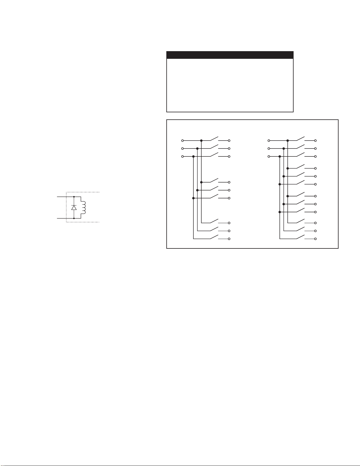
RELAY SWITCH CONFIGURATION:
1 bank of 3:1 mux 3-pole switching.
1 bank of 4:1 mux 3-pole switching.
CONTACT CONFIGURATION: 3-pole Form A.
CONNECTOR TYPE:
Mux Common Connector (1): 6-pin LEMO.
Mux Input/Output Connectors (7):3-pin LEMO.
Control Connectors (1):15-pin male D-sub.
MAXIMUM SIGNAL: 30V DC, 42V peak between any two inputs or
chassis, 1A switched, CATI.
CONTACT LIFE: Cold Switching:10 × 10
6
closures.
At Maximum Signal Levels:2 × 10
5
closures.
CHANNEL RESISTANCE(per conductor): <1Ω.
CONTACT POTENTIAL: <10µV per contact.
ACTUATION TIME: 3ms.
ISOLATION: Channel to Channel: >10
9
Ω, <80pF.
Common Mode: >10
9
Ω, <150pF.
CROSSTALK(1MHz, 50Ω load): <–40dB.
INSERTION LOSS (50Ω source, 50Ω load): <0.1dB ≤20kHz, >25dB @
2GHz.
RELAY DRIVE CURRENT(per relay): 8.5mA @ 24V (user supplied).
USER SUPPLIED VOLTAGE: 24V ± 4V DC, 175mA max.
RELAY CONTROL INPUT: Relay Closed: <2.0V.
Relay Open: User supplied voltage.
RELAY DRIVE CONFIGURATION:
User
Supplied
Voltage
Relay
Control
Input
Relay
Coil
Card
GENERAL
ENVIRONMENT:Operating: 0° to 50°C, up to 35°C <80% RH.
Storage: –25° to 65°C.
EMC: Conforms with European Union Directive 89/336/EEC, EN
55011, EN 50082-1, EN 61000-3-2 and 61000-3-3, FCC part 15
class B.
SAFETY: Conforms with European Union Directive 73/23/EEC, EN
61010-1.
DIMENSIONS: 152mm long × 102mm wide × 13mm deep (6˝ × 4˝
×
1
⁄2˝).
3:1 MUX 3-Pole Switch 4:1 MUX 3-Pole Switch
Page 8

T able of Contents
1 General Information
Introduction ................................................................................ 1-2
Feature overview ........................................................................ 1-2
Warranty information ................................................................. 1-2
Manual addenda ......................................................................... 1-2
Safety symbols and terms .......................................................... 1-3
Specifications ............................................................................. 1-3
Unpacking and Inspection .......................................................... 1-3
Inspection for damage ......................................................... 1-3
Handling precautions .......................................................... 1-3
Shipment contents ............................................................... 1-4
Instruction manual .............................................................. 1-4
Repacking for shipment ...................................................... 1-4
Recommended connectors ......................................................... 1-4
2 Connections
Introduction ................................................................................ 2-2
Handling precautions ................................................................. 2-2
Card configuration ...................................................................... 2-3
Card layout .......................................................................... 2-3
Simplified schematic ........................................................... 2-4
Card connections ........................................................................ 2-5
Input/output connectors ...................................................... 2-5
AUDIO IN and AUDIO OUT connector ............................ 2-6
CONTROL/MEASURE/POWER connector ...................... 2-7
Relay power and control ............................................................ 2-7
3 Operating Considerations
Introduction ................................................................................ 3-2
Maximum signal considerations ................................................ 3-2
Relay power and control ............................................................ 3-2
Switching considerations ........................................................... 3-2
Keeping connectors clean ................................................... 3-2
Path isolation ....................................................................... 3-3
Insertion loss ....................................................................... 3-4
Crosstalk ............................................................................. 3-4
RFI/EMI .............................................................................. 3-4
Ground loops ....................................................................... 3-5
Page 9

4 Service Information
Introduction ................................................................................ 4-2
Handling and cleaning precautions ............................................ 4-2
Handling precautions ........................................................... 4-2
Card cleaning ....................................................................... 4-2
Performance verification ............................................................. 4-3
Environmental conditions .................................................... 4-3
Recommended equipment ................................................... 4-3
Multiplexer card connections .............................................. 4-4
Channel resistance tests ....................................................... 4-4
Contact potential tests ......................................................... 4-5
Channel-to-channel isolation tests ...................................... 4-6
Common-mode isolation tests ............................................. 4-7
Replacing components ................................................................ 4-8
Replacement parts ............................................................... 4-8
Replacement precautions ..................................................... 4-8
Soldering considerations ..................................................... 4-8
Disassembly ........................................................................ 4-8
5 Replaceable Parts
Introduction ................................................................................ 5-2
Parts list ...................................................................................... 5-2
Ordering information .................................................................. 5-2
Factory service ............................................................................ 5-2
Component layout and schematic diagram ................................. 5-3
Page 10

List of Illustrations
2 Connections
Figure 2-1 Card configuration ................................................................. 2-3
Figure 2-2 Simplified schematic .............................................................. 2-4
Figure 2-3 Input/output connector terminal designations ........................ 2-5
Figure 2-4 AUDIO IN AUDIO OUT connector terminals ....................... 2-6
Figure 2-5 CONTROL/MEASURE/POWER connector terminals ......... 2-7
3 Operating Considerations
Figure 3-1 Path isolation resistance ......................................................... 3-3
Figure 3-2 Voltage attenuation by path isolation resistance .................... 3-4
Figure 3-3 Ground loops ......................................................................... 3-5
Figure 3-4 Eliminating ground loops ...................................................... 3-5
4 Service Information
Figure 4-1 Channel resistance test connections ....................................... 4-4
Figure 4-2 Contact potential connections ................................................ 4-5
Figure 4-3 Channel-to-channel isolation connections ............................. 4-6
Figure 4-4 Common-mode isolation connections ................................... 4-7
Page 11

List of T ables
2 Connections
Table 2-1 Input/output connector terminals ........................................... 2-5
Table 2-2 AUDIO IN AUDIO OUT connector terminals ....................... 2-6
Table 2-3 CONTROL/MEASURE/POWER connector terminals ......... 2-7
4 Service Information
Table 4-1 Recommended verification equipment ................................... 4-3
5 Replaceable Parts
Table 5-1 Parts list .................................................................................. 5-3
Page 12

1
General Information
Page 13

1-2 General Information
Introduction
This section contains general information about the Model 7999-2 Three-Pole Multiplexer
Card. The information is organized as follows:
• Feature overview
• Warranty information
• Manual addenda
• Safety symbols and terms
• Specifications
• Unpacking and inspection
• Recommended mating connectors
If you have any questions after reviewing this information, please contact your local
Keithley representative or call a Keithley Applications Engineer at 1-800-348-3735 (U.S. and
Canada only). Worldwide phone numbers are listed at the front of this manual.
Feature overview
The Model 7999-2 is a three-pole multiplexer card with the following features:
• One bank of 3:1 multiplexer 3-pole switching
• One bank of 4:1 multiplexer 3-pole switching
• External relay control and +24V DC power connections
• Lemo style connectors for multiplexer input/output and common connections
• Low insertion loss for audio frequencies (<0.1dB up to 20kHz)
W arranty information
Warranty information is located at the front of this instruction manual. Should your Model
7999-2 require warranty service, contact a Keithle y representative or an authorized repair facility in your area for further information. When returning the card for repair, be sure to fill out
and include the service form at the back of this manual to provide the repair facility with the
necessary information.
Manual addenda
Any improvements or changes concerning the multiplexer card or manual will be explained
in an addendum included with the manual. Be sure to note these changes and incorporate them
into the manual.
Page 14

General Information 1-3
Safety symbols and terms
The following symbols and terms may be found on the multiplexer card or used in this
manual.
The symbol indicates that the user should refer to the operating instructions located in
!
the manual.
The
symbol
safety precautions to avoid personal contact with these voltages.
The
WARNING heading used in this manual explains dangers that might result in personal
injury or death. Always read the associated information very carefully before performing the
indicated procedure.
shows that high voltage may be present on the terminal(s). Use standard
The
CAUTION heading used in this manual explains hazards that could damage the multi-
plexer card. Such damage may invalidate the warranty.
Specifications
Full Model 7999-2 specifications are included at the front of this manual.
Unpacking and Inspection
Inspection for damage
The Model 7999-2 is packaged in a re-sealable, anti-static bag to protect it from damage due
to static discharge and from contamination that could degrade its performance. Before removing the card from the bag, observe the precautions on handling discussed below.
Handling precautions
• Always grasp the card by the covers. Do not touch board surfaces or components.
• After removing the card from its anti-static bag, inspect it for any obvious signs of
physical damage. Report any such damage to the shipping agent immediately.
• When the card is not installed and connected, keep the card in its anti-static bag, and
store it in the original packing carton.
Page 15

1-4 General Information
Shipment contents
The following items are included with every Model 7999-2 order:
• Model 7999-2 Three-Pole Multiplexer Card
• Model 7999-2 Instruction Manual
• Additional accessories as ordered
Instruction manual
If an additional Model 7999-2 Instruction Manual is required, order the manual package,
Keithley part number 7999-2-901-00. The manual package includes an instruction manual and
any pertinent addenda.
Repacking for shipment
Should it become necessary to return the Model 7999-2 for repair, carefully pack the unit in
its original packing carton or the equivalent, and perform the following:
• Call the Repair Department at 1-800-552-1115 for a Return Material Authorization
(RMA) number.
• Advise as to the warranty status of the card.
• Write ATTENTION REPAIR DEPARTMENT and the RMA number on the shipping
label.
• Fill out and include the service form located at the back of this manual.
Recommended connectors
The following mating connectors and receptacles are recommended for use with Model
7999-2 jacks:
• For 3-pin Lemo jack: Lemo FGG.0B.303 series mating plug
• For 6-pin Lemo jack: Lemo FGG.2K.306 series mating plug
• For 15-pin D-sub: AMP 747303-3 series mating receptacle
Page 16

2
Connections
Page 17

2-2 Connections
Introduction
This section contains information about overall card configuration and connections and is
organized as follows:
• Handling precautions
• Card configuration
• Connections
WARNING The procedures in this section are intended only for qualified service per-
sonnel. Do not perform these procedures unless you are qualified to do so.
Failure to recognize and observe normal safety precautions could result in
personal injury or death.
Handling precautions
To maintain high-impedance isolation between channels, care should be taken when handling the card to avoid contamination from such foreign materials as body oils. Such contamination can reduce isolation resistance. To avoid possible contamination:
• Always grasp the card by the case.
• Do not touch connector insulators.
• Operate the card in a clean environment. If the card becomes contaminated, it should be
thoroughly cleaned as explained in Section 4.
Page 18

Connections 2-3
Card configuration
Card layout
Figure 2-1 shows the general layout of the Model 7999-2. Connectors include:
• Input/output connectors — A 3-pin Lemo connector is provided for each of the seven
multiplexer input/output channels (XEAR, BUZZ_MIC, EAR_MIC,
LEVELING_MIC, XMIC, LSP, SPECIAL_AUDIO).
• AUDIO_IN AUDIO_OUT — A 6-pin Lemo connector provides audio input/output
terminals.
• CONTROL/MEASURE/POWER — This DB-15 connector provides terminals for
relay control, DVM measurement connections, and +24V DC power connections.
Figure 2-1
Card configuration
Input/Output
Connectors
XEAR
BUZZ_MIC
EAR_MIC
LEVELING_MIC
XMIC
LSP
SPECIAL_AUDIO
MODEL 7999-2
42V MAX.
!
ANY CONDUCTOR
MADE IN
U.S.A.
CONTROL/
MEASURE/
POWER
AUDIO_IN
AUDIO_OUT
CONTROL/
MEASURE/
POWER
Connector
AUDIO IN
AUDIO OUT
Connector
Page 19

2-4 Connections
Simplified schematic
into two multiplexer banks:
NOTE Single pole switching is shown in Figure 2-2 for simplicity. H, L, and G indicates
Figure 2-2 shows a simplified schematic diagram of the Model 7999-2. The card is arranged
• One bank of 3:1 3-pole switching
• One bank of 4:1 switching
separate HI, LOW, and GND signal switching. + and - switched to HI and LOW
where applicable. See the schematic diagram at the end of Section 5 for details.
Figure 2-2
Simplified schematic
XEAR
(H,L,G)
BUZZ_MIC
(H,L,G)
EAR_MIC
(H,L,G)
LEVELING_MIC
(H,L,G)
XMIC
(H,L,G)
LSP
(H,L,G)
SPECIAL_AUDIO
(H,L,G)
NOTE: Single-pole switching shown for simplicity. H, L, G
indicate separate HI, LOW, and GND signals. + and
- switched to HI and LOW where applicable.
AUDIO_IN
(H,L,G)
DVM (+,-)
MEASVOLT (+,-)
AUDIO_OUT
(H,L,G)
Page 20

Card connections
Input/output connectors
Figure 2-3 provides the terminal configuration for the input/output connectors (XEAR,
BUZZ_MIC, EAR_MIC, LEVELING_MIC, XMIC, LSP, SPECIAL_AUDIO), while Table
2-1 summarizes signals.
Table 2-1
Input/output connector terminals
Connector pin Signal
Connections 2-5
1
2
3
Figure 2-3
Input/output connector
terminal designations
HI
LOW
GND
1
23
Page 21

2-6 Connections
AUDIO IN and AUDIO OUT connector
Table 2-2 summarizes signals.
Table 2-2
AUDIO IN AUDIO OUT connector terminals
Connector pin Signal
Figure 2-4 shows the terminal configuration for the AUDIO IN AUDIO OUT connector, and
Figure 2-4
AUDIO IN
AUDIO OUT
connector terminals
1
2
3
4
5
6
AUDIO OUT HI
AUDIO OUT LO
AUDIO OUT GND
AUDIO IN HI
AUDIO IN LO
AUDIO IN GND
1
2
5
6
4
3
Page 22

CONTROL/MEASURE/POWER connector
Figure 2-5 shows the terminal configuration for the CONTROL/MEASURE/POWER connector, and Table 2-3 summarizes terminal designations along with switched signals.
Table 2-3
CONTROL/MEASURE/POWER connector terminals
Terminal Description Switched signal(s)
Connections 2-7
1
2
3
4
5
6
7
8
9
10
11
12
13
14
15
Figure 2-5
CONTROL/MEASURE/
POWER connector terminals
DVM+
CONTROL 6
DVMCONTROL 7
+24V
CONTROL 8
CONTROL 1
CONTROL 9
CONTROL 2
MEASVOLT+
CONTROL 3
MEASVOLTCONTROL 4
NO CONNECTION
CONTROL 5
18
Relay power and control
EAR_MIC
MEASVOLT, LEVELING_MIC
XMIC
XMIC
XEAR
AUDIO_OUT
SPECIAL_AUDIO
XEAR
AUDIO_IN
915
To control relays, +24V DC must be applied to pin 5 of the CONTROL/MEASURE/
POWER connector. A relay channel can be closed by setting the associated CONTROL line
listed in Table 2-3 low.
Page 23

3
Operating Considerations
Page 24

•
•
3-2 Operating Considerations
Introduction
This section contains information about operating considerations for the Model 7999-2
Three-Pole Multiplexer Card. The information is organized as follows:
• Maximum signal considerations
• Relay power and control
• Switching considerations
Maximum signal considerations
WARNING Maximum voltage between any conductor and ground is 42V.
CAUTION T o prevent damage to the Model 7999-2, do not exceed the following maxi-
mum signal level specifications of the card:
Maximum voltage: 30V DC, 42V peak
Maximum current: 1A DC, switched
Relay power and control
To control relays, an external +24V DC voltage source must be connected to pin 5 of the
CONTROL/MEASURE/POWER connector. A channel is closed by setting the corresponding
control signal low. See Section 2 for complete connection information. Table 2-3 in Section 2
lists switched signals.
Switching considerations
Signals switched by the Model 7999-2 may be subject to various effects that can seriously
affect their integrity. The following paragraphs discuss these effects and ways to minimize
them.
Keeping connectors clean
As is the case with any high-resistance device, the inte grity of connectors can be damaged if
they are not handled properly. If connector insulation becomes contaminated, the insulation
resistance will be substantially reduced, affecting high-impedance measurement paths.
Oils and salts from the skin can contaminate connector insulators, reducing their resistance.
Also, contaminants present in the air can be deposited on the insulator surface. To avoid these
Page 25

Operating Considerations 3-3
problems, never touch the connector insulating material. In addition, the multiplexer card
should be used only in clean, dry environments to avoid contamination.
If the connector insulators should become contaminated, either by inadvertent touching, or
from air-borne deposits, they can be cleaned with a cotton swab dipped in clean methanol.
After thoroughly cleaning, they should be allowed to dry for several hours in a low-humidity
environment before use, or they can be dried more quickly using dry nitrogen.
Path isolation
The path isolation is simply the equivalent impedance between any two test paths in a measurement system. Ideally, the path isolation should be infinite, but the actual resistance and distributed capacitance of cables and connectors results in less than infinite path isolation values
for these devices.
Figure 3-1
Path isolation
resistance
Path isolation resistance forms a signal path that is in parallel with the equivalent resistance
of the DUT , as sho wn in Figure 3-1. For lo w-to-medium de vice resistance values, path isolation
resistance is seldom a consideration; however, it can seriously degrade measurement accuracy
when testing high-impedance devices. The v oltage measured across such a de vice, for example,
can be substantially attenuated by the voltage divider action of the device source resistance and
path isolation resistance, as shown in Figure 3-2. Also, leakage currents can be generated
through these resistances by voltage sources in the system.
R
DUT
R
PATH
E
DUT
DUT MUX
= Source Resistance of DUT
R
DUT
E
= Source EMF of DUT
DUT
R
= Path Isolation Resistance
PATH
= Input Resistance of Measuring Instrument
R
IN
Card
R
IN
Measure
Instrument
V
Page 26

Ω
Ω
3-4 Operating Considerations
Figure 3-2
Voltage attenuation by
path isolation
resistance
Insertion loss
various signal path components through the card (connectors, PC board traces, and relays). The
Model 7999-2 has an insertion loss figure of <0.1dB at audio frequencies up to 20kHz (50
source and load impedances), which should not be a consideration in most cases.
Crosstalk
With similar power levels applied to the various channels, crosstalk will be of little consequence. W ith widely different power levels, however , crosstalk may result in undesired results.
Note that the Model 7999-2 has crosstalk figure of <-40db @ 1MHz (50
R
DUT
E
DUT
E
=
E
OUT
R
DUTRPATH
R
DUTRPATH
+
PATH
Insertion loss indicates signal lost while passing through the card. This loss occurs in the
The crosstalk figure indicates the amount of signal leakage between channels on the card.
load).
RFI/EMI
terms used to describe electromagnetic interference over a wide range of frequencies across the
spectrum. Such interference can be particularly troublesome at low signal le vels, b ut is can also
affect measurements at high levels if the problem is of sufficient severity.
types of electronic equipment (microprocessors, high speed digital circuits, etc.), or it can
result from impulse sources, as in the case of arcing in high-voltage environments. In either
case, the effect on the desired signal can be considerable if enough of the unwanted signal is
present.
and signal leads as far away from the RFI source as possible. Shielding the switching card, signal leads, sources, and measuring instruments will often reduce RFI to an acceptable level. In
extreme cases, a specially constructed screen room may be required to sufficiently attenuate the
troublesome signal.
RFI (Radio Frequency Interference) and EMI (Electromagnetic Interference) are general
EMI can be caused by steady-state sources such as radio or TV broadcast signals, or some
EMI can be minimized in several ways. The most obvious method is to keep the equipment
Page 27

Ground loops
When two or more devices are connected together, care must be taken to avoid unwanted
signals caused by ground loops. Ground loops usually occur when devices are connected with
more than one signal return path such as power line ground. As shown in Figure 3-3, the resulting ground loop causes current to flow through LO signal leads and then back through power
line ground. This circulating current develops a small but undesirable voltage between the LO
terminals of the two devices. This voltage will be induced into the desired signal affecting its
integrity.
Operating Considerations 3-5
Figure 3-3
Ground loops
Figure 3-4
Eliminating
ground loops
Signal Leads
Device 1 Device 2 Device 3
Ground
Loop
Current
Power Line Ground
Figure 3-4 shows how to connect several devices together to eliminate this type of ground
loop problem. Here, only one device is connected to power line ground.
Ground loops are not normally a problem with isolated LO terminals. However, all devices
in the test setup may not be designed in this manner . When in doubt, consult the manual for all
instrumentation in the test setup.
Device 1 Device 2 Device 3
Power Line Ground
Page 28

4
Service Information
Page 29

4-2 Service Information
Introduction
This section contains service information for the Model 7999-2. The information is orga-
nized as follows:
• Handling and cleaning precautions
• Performance verification
• Component replacement
WARNING The information in this section is intended only for qualified service per-
sonnel. Some of the procedures may expose you to hazardous voltages that
could result in personal injury or death. Do not perform these procedures
unless you are qualified to do so.
Handling and cleaning precautions
Because of the high-impedance areas on the Model 7999-2, care should be taken when handling or servicing the card to prevent possible contamination. The follo wing precautions should
be observed when servicing the card.
Handling precautions
Observe the following precautions when handling the multiplexer card:
• Handle the card only by the edges and cover.
• Do not touch connector insulators.
• Do not touch any board surfaces or components not associated with the repair.
• Do not touch areas adjacent to electrical contacts.
• When servicing the card, wear clean cotton gloves.
• Do not store or operate the card in an environment where dust could settle on the circuit
board.
Card cleaning
• Use dry nitrogen gas to clean any dust off the circuit board and components.
• Clean the contaminated area with methanol, then blow dry the entire board with dry
nitrogen gas.
• After cleaning, allow the card to dry in a 50˚C low-humidity environment for several
hours before use.
Page 30

Ω
Ω
Service Information 4-3
Performance verification
The following paragraphs discuss performance verification procedures for the Model
7999-2, including channel resistance, contact potential, and channel-to-channel and commonmode isolation.
CAUTION Contamination will degrade the performance of the card. To avoid
contamination, always grasp the card by the cover; do not touch the
connectors.
NOTE F ailur e of any performance verifi cation test may indicate that the multiple xer card is
contaminated. See “Handling and cleaning precautions” earlier in this section for
information on cleaning the card.
Environmental conditions
All verification measurements should be made at an ambient temperature between 18˚ and
28˚C, and at a relative humidity of less than 70%.
Recommended equipment
Table 4-1 summarizes the equipment necessary for performance verification, along with an
application for each unit.
Table 4-1
Recommended verification equipment
Description Manufacturer/Model Specifications Test
Digital Multimeter
Nanovoltmeter
Electrometer
Test Lead Sets (2)
Low Thermal Cable
Triax Cable
Keithley 2010
Keithley 2182
Keithley 6517A
Keithley 1681
Keithley 2107-4
Keithley 237-ALG-2
10
range, 60ppm
10mV range, 50ppm
2G
range, 0.225%
Banana plug/clips
Low thermal/lugs
Triax/clips
Channel resistance
Contact potential
Isolation
Channel resistance
Contact potential
Isolation
Page 31

Ω
Ω
Ω
Ω
4-4 Service Information
Multiplexer card connections
Test equipment connection diagrams in this section are generic in nature and are intended
only to show basic connections on how to connect test equipment to the relay contact(s) under
test. See Section 2 for complete details on card connections and terminal designations.
Channel resistance tests
Perform the following steps to verify that each contact of e v ery relay is closing properly and
that the channel resistance is within specification.
1. Turn on the Model 2010 DMM, and allow it to warm up for one hour before making
measurements.
2. Set the Model 2010 to the 10
SENSE
3. Short the free ends of the four test leads together, and enable REL on the Model 2010 to
null out residual resistance. Leave REL enabled for the entire test.
4. Connect the Model 2010 INPUT and SENSE
tested, as shown in Figure 4-1. Note that 4-wire connections to the card terminals are
used.
5. Close the relay being tested.
6. Note the resistance reading on the Model 2010, and verify that it is <1
7. Open the relay being tested.
8. Repeat steps 4 through 7 for every relay contact on the card.
range, and connect the four test leads to the INPUT and
4 WIRE jacks.
4 WIRE jacks to the relay contact to be
.
Figure 4-1
Channel resistance
test connections
TALK
LSTN
SRQ
SHIFT
TIMER
MX+B
SHIFT
DCV
LOCAL
EX TRIG
POWER
OPEN CLOSE
STEP CH2 CH3 CH4 CH5 CH6 CH7 CH8 CH9 CH10
CH1REM
SCAN
HOLD TRIG FAST MED SLOW AUTO ERR
REL FILT
dBm
%
dB
CONT
ACI
SAVE SETUP
ACV
HOLD
TRIG
DCI
LIMITS ON/OFFDELAY
STORE
CONFIG HALT
STEP SCAN
RECALL
Ω2 Ω4
TYPE
GPIB
DIGITS RATE
RATIO
RELFILTER
RS232
Model 2010 DMM
Connect to INPUT and SENSE
SENSE
INPUT
Ω 4 WIRE
HI
350V
1000V
!
PEAK
PEAK
LO
500V
PEAK
INPUTS
F
R
AUTO
FRONT/REAR
3A 250V
AMPS
BUFFER
STAT
PERIOD SENSOR
FREQ
DRYCKT O COMP
CAL TEST
EXIT ENTER
MATH
REAR
4W
2010 MULTIMETER
TEMP
RANGE
RANGE
In
H
L
G
Out
Model 7999-2 Relay
Under Test. See Section 2
for Detailed Connections.
Close
Relay
Page 32

µ
Contact potential tests
Perform the following procedure to check contact potential of each relay contact:
1. Connect the low-thermal cable to the Model 2182 Nanovoltmeter INPUT jack.
2. Turn on the Model 2182, and allow the unit to warm up for one hour to achieve rated
accuracy.
3. Select the Model 2182 10mV range.
4. Temporarily short the Channel 1 HI and LO leads of the low-thermal cable.
5. Enable REL on the Model 2182.
6. Connect the Model 2182 to the relay contact being tested, as shown in Figure 4-2. Be
sure to make connections to the Channel 1 input terminals, and use that channel for
measurements.
7. Close the relay being tested.
8. Verify that the Model 2182 reading is <10
9. Open the relay being tested.
10. Repeat steps 6 through 9 for all relays on the card.
Service Information 4-5
V.
Figure 4-2
Contact potential
connections
SHIFT
LOCAL
POWER
SCAN
CH1REM
STEP CH2 CH3 CH4 CH5 CH6 CH7 CH8 CH9 CH10
TALK
LSTN
SRQ
SHIFT
TIMER
HOLD TRIG FAST MED SLOW AUTO ERR
V1-V
2
%
MX+B
DCV1
DELAY
EX TRIG
CONFIG HALT
STEP SCAN
L
DCV2
1
/
V
2
V
HOLD
BUFFER
TRIG
STORE
RECALL
SETUP
SAVE RESTR
BUFFER
REL FILT
SYNC
ACAL
TYPE
FILT REL
LIMITS
GPIB
DIGITS RATE
OUTPUT
ON/OFFVALUE
RS232
STAT
2182 NANOVOLTMETER
A
OUT
TEMP
1
CAL TEST
EXIT ENTER
Model 2182 Nonovoltmeter
MATH
REAR
4W
TCOUPL
Close
Relay
CHANNEL 1
LO
HI
HI
CHANNEL 2
RANGE
RANGE
120V MAX
AUTO
12V MAX
CAT I
350V PEAK ANY
TERMINAL TO CHASSIS
TEMP
2
Low Thermal Cable
!
LO
Connect to and
use Channel 1
In
H
L
G
Out
Model 7999-2 Relay
Under Test. See Section 2
for Detailed Connections.
Page 33

4-6 Service Information
WARNING:NO INTERNAL OPERATOR SERVICABLE PARTS,SERVICE BY QUALIFIED PERSONNEL ONLY.
WARNING:NO INTERNAL OPERATOR SERVICABLE PARTS,SERVICE BY QUALIFIED PERSONNEL ONLY.
CAUTION:FOR CONTINUED PROTECTION AGAINST FIRE HAZARD,REPLACE FUSE WITH SAME TYPE AND RATING.
CAUTION:FOR CONTINUED PROTECTION AGAINST FIRE HAZARD,REPLACE FUSE WITH SAME TYPE AND RATING.
Channel-to-channel isolation tests
CAUTION The following procedure uses the Model 6517A voltage source to measure
Perform the following steps to check channel-to-channel isolation:
1. Turn on the Model 6517A Electrometer, and allow the unit to warm up for one hour
before testing.
2. Select the Model 6517A ohms function and 2G
sure the voltage source is in standby.
3. Connect the electrometer to the two Model 7999-2 channels being tested, as shown in
Figure 4-3. Note that electrometer INPUT HI is connected to one channel, while
VOLTAGE SOURCE HI is connected to the other channel.
4. Put the Model 6517A in the manual ohms mode, and set the voltage source to +30V.
5. Place the Model 6517A voltage source in operate, and disable zero check.
6. Allow the reading to settle, then verify that the resistance reading is >1G
7. Enable zero check, and place the Model 6517A voltage source in standby.
8. Repeat steps 3 through 7 for all other two-channel combinations on the card.
Ω
Ω
resistance. To avoid damage to the Model 7999-2, use the Model 6517A
manual ohms mode to limit the test voltage to 30V as outlined in the procedure.
range, and enable zero check. Make
.
Figure 4-3
Channel-to-channel
isolation connections
INPUT
!
INPUT
250V PEAK
Voltage Source HI
PREAMP OUT
TEMP
TYPE K
250 PEAK
COMMON 2V ANALOG
OPTION SLOT
OUTPUT
HUMIDITY
LO
750V
PEAK
EXT TRIGINMTR COMP
RS232
Model 6517A Electrometer
1010V
PEAK
V SOURCE
!
INTERLOCK
Close
Relay
Connect INPUT HI
In
H
to First Relay
L
G
HI
SELECTED
LINE VOLTAGE
90-110V
180-220V
105-125V
210-250V
LINE RATING
50-60HZ
115V
50VA MAX
DIGITAL
AC ONLY
(CHANGE IEEE ADDRESS
WITH FRONT PANEL MENU)
TRIG LINK
I/O
OUT
IEEE-488
LINE FUSE
SLOWBLOW
1/2A 90-125V
1/4A 180-250V
MADE
IN
U.S.A.
Out
Close
Relay
In
H
L
Connect Voltage
Source HI to
Second Relay
G
Out
Model 7999-2 Relays Under Test. See
Section 2 for Detailed Connections.
Page 34

WARNING:NO INTERNAL OPERATOR SERVICABLE PARTS,SERVICE BY QUALIFIED PERSONNEL ONLY.
WARNING:NO INTERNAL OPERATOR SERVICABLE PARTS,SERVICE BY QUALIFIED PERSONNEL ONLY.
CAUTION:FOR CONTINUED PROTECTION AGAINST FIRE HAZARD,REPLACE FUSE WITH SAME TYPE AND RATING.
CAUTION:FOR CONTINUED PROTECTION AGAINST FIRE HAZARD,REPLACE FUSE WITH SAME TYPE AND RATING.
Ω
Ω
Common-mode isolation tests
CAUTION The following procedure uses the Model 6517A voltage source to measure
resistance. To avoid damage to the Model 7999-2, use the Model 6517A
manual ohms mode to limit the test voltage to 30V as outlined in the
procedure.
Perform the following steps to check common-mode isolation:
1. Turn on the Model 6517A Electrometer, and allow the unit to warm up for one hour
before testing.
2. Select the Model 6517A ohms function and 2G
sure the voltage source is in standby.
3. Connect the electrometer to the Model 7999-2 channel being tested, as shown in Figure
4-4. Note that electrometer INPUT HI is connected to the tested channel, while VOLTAGE SOURCE HI is connected to system ground.
4. Put the Model 6517A in the manual ohms mode, and set the voltage source to +30V.
5. Place the Model 6517A voltage source in operate, and disable zero check.
6. Allow the reading to settle, then verify that the resistance reading is >1G
7. Enable zero check, and place the Model 6517A voltage source in standby.
8. Repeat steps 3 through 7 for all other channels on the card.
Service Information 4-7
range, and enable zero check. Make
.
Figure 4-4
Common-mode
isolation connections
INPUT
!
INPUT
250V PEAK
Voltage Source HI
PREAMP OUT
TEMP
TYPE K
250 PEAK
OPTION SLOT
COMMON 2V ANALOG
OUTPUT
HUMIDITY
LO
750V
PEAK
EXT TRIGINMTR COMP
RS232
Model 6517A Electrometer
V SOURCE
1010V
PEAK
!
INTERLOCK
Connect INPUT HI
to Relay
Close
Relay
HI
SELECTED
LINE VOLTAGE
90-110V
180-220V
105-125V
210-250V
LINE RATING
50-60HZ
115V
50VA MAX
DIGITAL
AC ONLY
(CHANGE IEEE ADDRESS
WITH FRONT PANEL MENU)
TRIG LINK
I/O
OUT
IEEE-488
LINE FUSE
SLOWBLOW
1/2A 90-125V
1/4A 180-250V
MADE
IN
U.S.A.
Connect Voltage
Source HI to
In
Out
H
L
G
System Ground
Model 7999-2 Relay
Under Test. See Section 2
for Detailed Connections.
Page 35

4-8 Service Information
Replacing components
Replacement parts
Replacement parts can be obtained directly from Keithley Instruments, Inc. See the parts list
in Section 5 for part numbers.
Replacement precautions
CAUTION Observe the following precautions when replacing components:
To avoid contamination, which could degrade card performance,
always handle the card only by the covers and side edges. Do not
touch the connector, board surfaces, or components on the card.
Use care when removing relays from the PC board to avoid pulling
traces away from the circuit board. Before attempting to remove a
relay, use an appropriate de-soldering tool, to clear each mounting
hole completely free of solder. Each relay pin must be free to move in
its mounting hole before removal. Also, make certain that no burrs are
present on the ends of the relay pins.
•
•
Soldering considerations
When using solder on the circuit board, observe the following precautions:
• Use an OA-based (organic activated) flux, and take care not to spread the flux to other
areas of the circuit board.
• Remove the flux from the work areas when the repair has been completed. Use pure
water along with clean cotton swabs or a clean soft brush to remove the flux.
• Once the flux has been removed, swab only the repaired area with methanol, then blow
dry the board with dry nitrogen gas.
• After cleaning, allow the card to dry in a 50˚C low-humidity environment for several
hours before use.
Disassembly
Perform the following steps to disassemble the Model 7999-2 to gain access to parts on the
circuit board:
1. Remove the six screws that hold the case together.
2. Remove the nuts that secure the seven input/output connectors to the case.
3. Separate the two halves of the case.
4. Unplug the connectors from the PC board.
5. Remove the screws that secure the PC board to the case, then remove the board.
Page 36

5
Replaceable Parts
Page 37

5-2 Replaceable Parts
Introduction
This section contains replacement parts information and component layout and schematic
drawings for the Model 7999-2.
Parts list
The parts list for the Model 7999-2 is shown in Table 5-1.
Ordering information
To place an order, or to obtain information concerning replacement parts, contact your
Keithley representative or the factory (see inside front cover for addresses). When ordering
parts, be sure to include the following information:
• Card model number (Model 7999-2)
• Serial number
• Part description
• Component designation (if applicable)
• Keithley part number
Factory service
If the card is to be returned to Keithley Instruments for repair, perform the following:
• Call the Repair Department at 1-800-552-1115 for a Return Material Authorization
(RMA) number.
• Complete the service form at the back of this manual, and include it with the
instrument.
• Carefully pack the instrument in the original packing carton.
• Write ATTENTION REPAIR DEPARTMENT and the RMA number on the shipping
label.
Page 38

Replaceable Parts 5-3
Component layout and schematic diagram
The following component layout and schematic diagram drawings are provided on the fol-
lowing pages:
• Component layout drawing: 7999-2-100
• Schematic diagram: 7999-2-106
Table 5-1
Parts list
Circuit designation Description Keithley part no.
C1-C40
CR1-CR16
J1,J2,J3,J4,J5,J6,J7
J8,J9
J10
K1-K16
L1-L41
CAP, 22PF, 10%, 100V, CERAMIC
DIODE, SWITCHING, 250MA, BAV103
CONN RT ANGLE RECEPTACLE
LATCHING HEADER, FRICTON, SGL ROW
CONN, HEADER STRAIGHT SOLDER PIN
NON-LATCHING RELAY
FERRITE BEAD
CONN, FIXED RECEPTACLE
CONNECTOR
CONNECTOR, HOUSING
TOP COVER
BOTTOM COVER
C-451-22P
RF-89
CS-1064
CS-724-3
CS-368-16
RL-233
CH-91
CS-1063
CS-236
CS-638-3
7999-2-301A
7999-2-302A
Page 39

Page 40

Page 41

Page 42

Page 43

Index
A
AUDIO IN and AUDIO OUT connector
C
Card cleaning
Card configuration
Card connections
Card layout
Channel resistance tests
Channel-to-channel isolation tests
Common-mode isolation tests
Component layout and schematic diagram
Connections
Contact potential tests
CONTROL/MEASURE/POWER
Crosstalk
2-3
connector
3-4
2-1
4-2
2-7
2-3
2-5
4-4
4-5
D
Disassembly
4-8
E
Environmental conditions
4-3
F
Factory service
Feature overview
5-2
1-2
G
General Information
Ground loops
1-1
3-5
H
Handling and cleaning precautions
Handling precautions
1-3
2-2
,
I
Input/output connectors
Insertion loss
Inspection for damage
Instruction manual
Introduction
1-2
3-4
2-5
1-3
1-4
2-2
3-2
,
,
,
4-2
4-7
,
,
4-2
5-2
4-6
4-2
K
Keeping connectors clean
3-2
M
2-6
Manual addenda
Maximum signal considerations
Multiplexer card connections
1-2
4-4
3-2
O
Operating considerations
Ordering information
3-1
5-2
P
5-3
Parts list
Path isolation
Performance verification
5-2
3-3
4-3
R
Recommended connectors
Recommended equipment
Relay power and control
Repacking for shipment
Replaceable parts
Replacement parts
Replacement precautions
Replacing components
RFI/EMI
3-4
1-4
4-3
2-7
,
3-2
1-4
5-1
4-8
4-8
4-8
S
Safety symbols and terms
Service information
Shipment contents
Simplified schematic
Soldering considerations
Specifications
Switching considerations
1-3
1-4
4-1
2-4
1-3
4-8
3-2
U
Unpacking and Inspection
1-3
W
Warranty information
1-2
Page 44

Keithley Instruments, Inc.
28775 Aurora Road
Cleveland, Ohio 44139
Printed in the U.S.A.
 Loading...