

Page 1
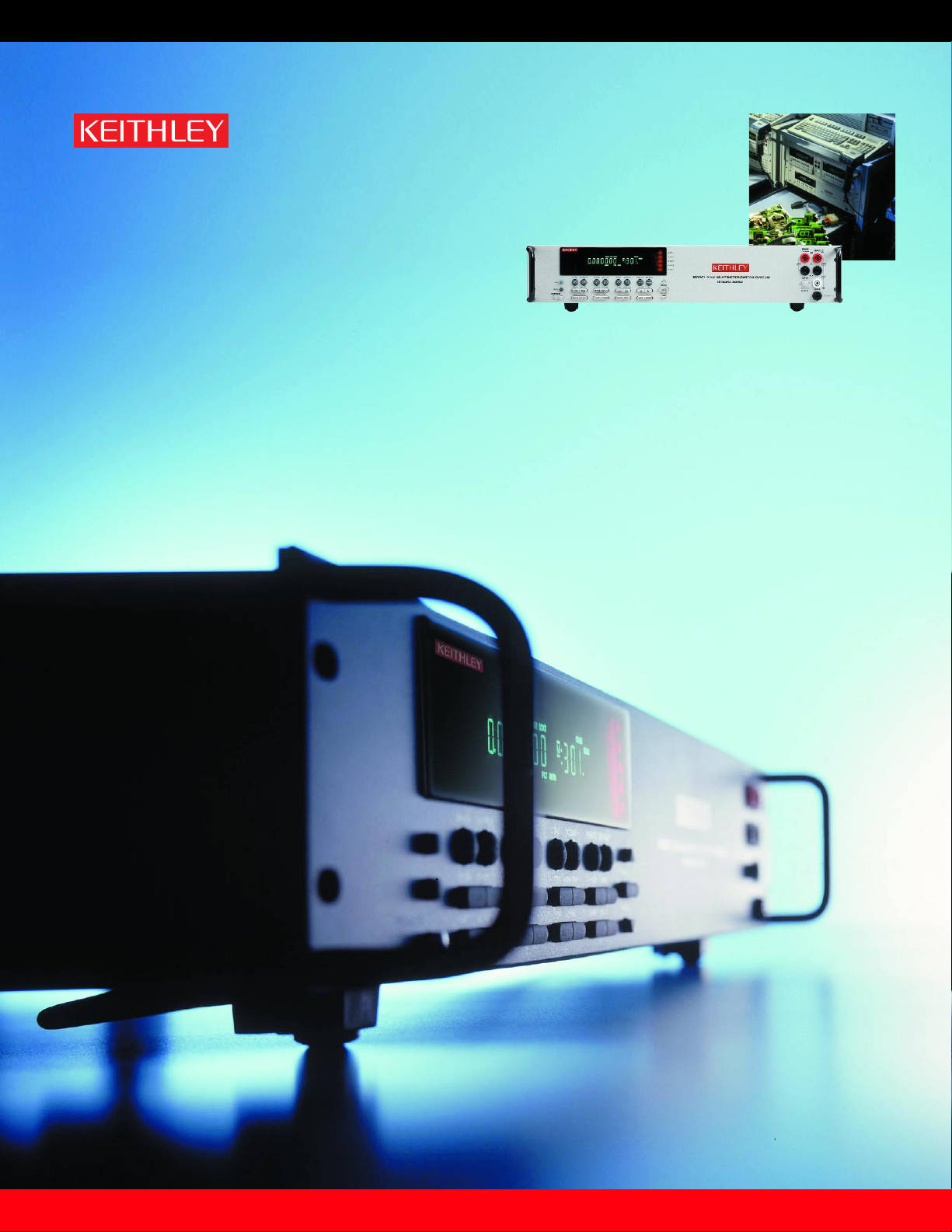
Next generation measurement, switching and control
solutions for ATE and data acquisition systems
www.keithley.com
A GREATER MEASURE OF CONFIDENCE
Model 2750 Multimeter/Switch System
Integra Series
Page 2
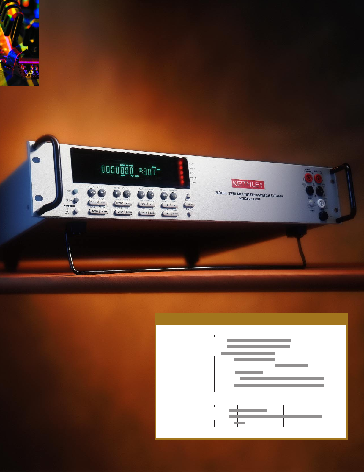
and control solutions
The Model 2750's high throughput,
wide measurement ranges, and
modular architecture make it an
ideal platform for applications like
production testing of electronic
components, subassemblies and
systems, accelerated stress testing
(including burn-in testing), process
monitoring and control, and
precision low-ohms measurements.
High channel-count measurement
HIGH-CHANNEL-COUNT TEST SOLUTIONS
MEASUREMENT RANGES
DC Voltage
AC Voltage
DC Current
AC Current
Frequency
Period
Resistance (2-Wire)
Resistance (4-Wire)
Logarithmic scale
Temperature–RTD
Temperature–TC
Temperature–Thermistor
Linear scale
Measurement Ranges
1n 1µ 1m 1 1k 1M 1G
100nV 1000V
100nV 750V
10nA 3A
1µA 3A
3Hz 500kHz
2µs 333ms
10µΩ 120MΩ
1µΩ 120MΩ
–500 0 500 1000 1500 2000
–200°C 630°C
–200°C 1820°C
–80°C 150°C
Page 3

The Model 2750 Multimeter/Switch System is an affordable
alternative to traditional high-channel-count test solutions like
rack-and-stack systems, dataloggers/recorders, VXI/PXI
systems, and plug-in card-based data acquisition equipment.
Like our popular Model 2700 Multimeter/Data Acquisition
System, it builds upon the powerful Integra Series platform.
The Model 2750 brings together high-speed measurement,
switching, and control capabilities for optimizing test processes
for a fraction of the cost of alternative solutions.
Modular platform handles today’s and
tomorrow’s applications
The system's flexible, five-slot mainframe combines a 6
1
⁄2-digit,
14-function DMM with support for up to 200 channels of
two-pole switching and multi-channel analog/digital I/O control.
This tight integration simplifies system design while it minimizes
rack space requirements. It also allows the Model 2750 to scan
and measure more than 200 channels per second, ensuring
shorter test times and greater productivity than competitive
approaches. Currently, the Model 2750 supports nine optional
plug-in switch/control modules and additional modules are
already in development. Up to five modules can be mixed or
matched to provide the combination of switching and control
capabilities today's ATE and data acquisition systems demand.
For the flexibility needed for tomorrow's applications, the
Model 2750's on-board flash memory can be reprogrammed to
support new Keithley modules as they are introduced.
Multi-channel low ohms measurements
you can trust
Expanded resistance measurement ranges allow the Model 2750
to address applications that normally require costly and complex
micro-ohmmeters, such as precision milli- or micro-ohm
measurements of connectors, harnesses, squibs, sensors,
semiconductors, and other low-ohms devices. Production-floor
features such as open test lead indication and an offset
compensation mode help eliminate troublesome "false failures"
than can result from problems with test stand wiring, connections,
relays, or cabling. The built-in 20mV clamp helps protect
sensitive DUTs from damage and prevents self-heating errors
during testing. The Model 2750 can also handle series lead
resistances of up to 80% of range and still meet specification—
this important capability helps ensure measurement integrity in
large, multipoint test system applications.
Benefits of an integrated design
The Model 2750 offers a variety of advantages over existing
solutions for ATE and data acquisition applications. For
example, its flexible modular architecture and integrated
measurement, switching, and control capabilities save rack
space by reducing the number of separate instruments needed.
This design also simplifies expanding the system as the number
of channels grows or re-purposing it as new test requirements
evolve. Its integrated signal conditioning, scaling, stimulus,
filtering and I/O capabilities eliminate the need for external
circuitry when designing and building data acquisition systems.
This architecture also makes it unnecessary to open the
computer to install plug-in boards. The Model 2750 offers
accuracy and repeatability superior to plug-in data acquisition
boards and VXI/PXI systems, while providing faster test times
than typical DMM/switch systems. This makes it possible to
combine higher test yields with higher test throughput.
for flexible, high-speed testing
FLEXIBLE MODULAR ARCHITECTURE
Latency
of switch
systems.
One channel
complete
Trigger
Model 2750
multimeter/
switch system
ADVANTAGES OF AN INTEGRATED SYSTEM
Typical
switch/control
unit and digital
multimeter
Close relayMeasure
Relay
closing
latency
One channel
complete
Close
relay of
switch/co
ntrol unit
Acknowledge
that relay is
closed, trigger
DMM
Trigger
settle
DMM
measure
Acknowledge
that
measurement
is done,
trigger switch
latency
of
switch
Close relay
on switch/
control unit
Page 4
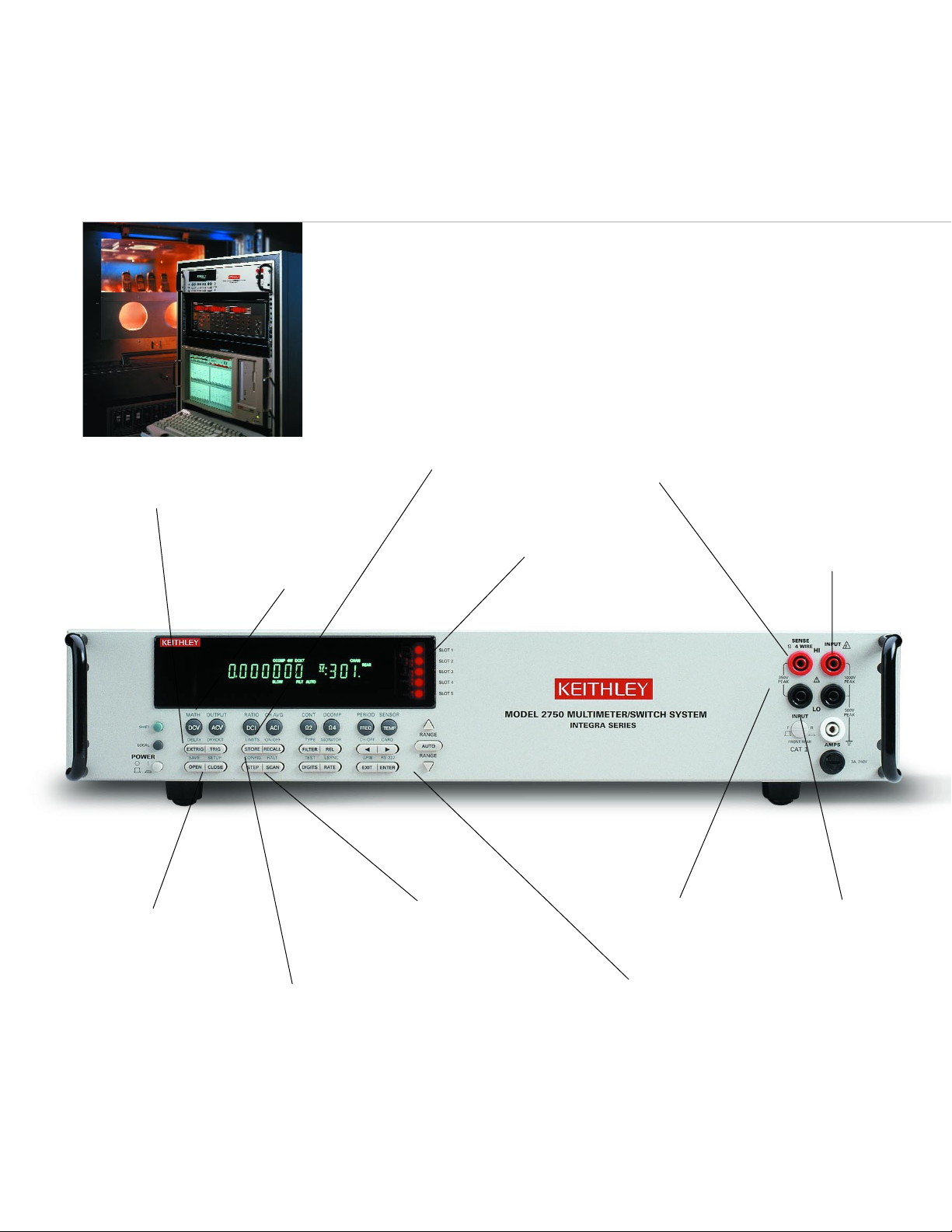
Built-in independently programmable
alarm limits per channel.
View slot capacity and channel
closure status from front panel.
Front panel input jacks simplify
manual probing, troubleshooting,
and calibration.
Open lead detection protects
against false readings due to
lead disconnections.
Familiar DMM-like front panel scheme makes
it easier to use on bench or rack.Select or
change functions with the push of a button.
Voltage clamp ohms
(dry circuit) clamps open
circuit voltage to 20mV.
Non-volatile memory allows time-
stamped storage of 110K readings.
Has built-in real-time clock.
Open or close single
or multiple channels
from the front panel.
Manually step through channels or
scan automatically. Each channel
independently configurable.
Initialize the system with one
of three fully programmable
set-up conditions.
Use mX+b or 1/x% scaling to
convert sensor/transducer
outputs directly into
engineering units.
1Ω range with
1µΩ resolution.
The Model 2750 provides
wide measurement ranges
FAMILIAR DMM-LIKE FRONT PANEL
Page 5
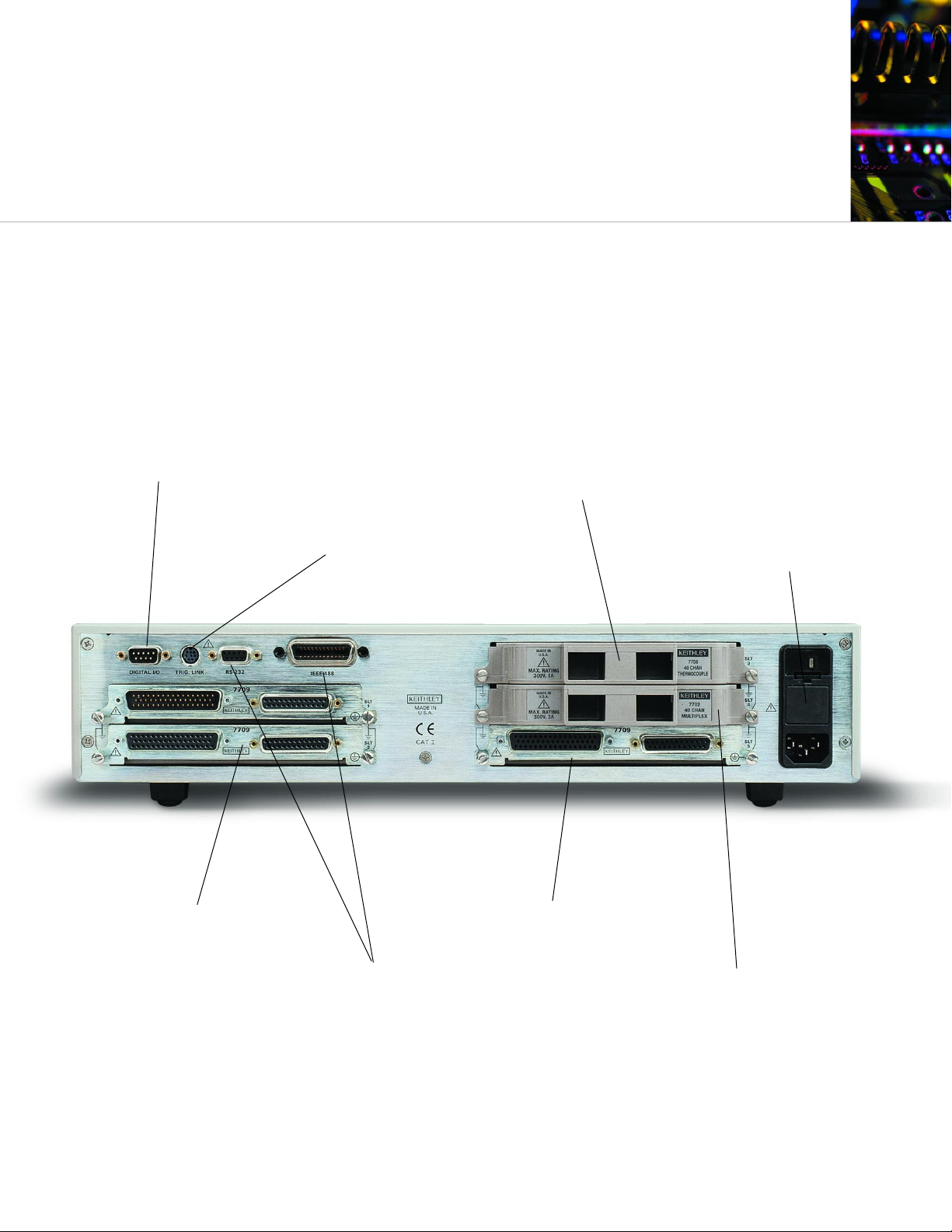
Built-in digital I/O lines provide
for control,external triggering,and
HI/LO alarm/limit outputs.
Trigger Link enables tightly
synchronized triggering with other
instruments in large ATE systems.
GPIB and RS-232
interfaces are standard.
Built-in noise rejection
circuitry ensures stable,
predictable measurements.
IDC connectors on selected
modules are compatible with
standard ribbon cable.
Rugged D-sub bulkhead
connectors on selected modules.
Built-in relay cycle counters on each
module for ease of maintenance.
A variety of measurement and control modules make it
simple to mix, match, and change input signals or control
lines whenever needed. Install up to five modules at once
to create a system of up to 200 channels.
For detailed technical specifications on the Model 2750 Multimeter/Switch System,request a copy
of the Model 2750 Technical Specification Booklet,or visit our website:www.keithley.com
and a modular architecture
SIMPLE TO MIX, MATCH, AND CHANGE
Page 6
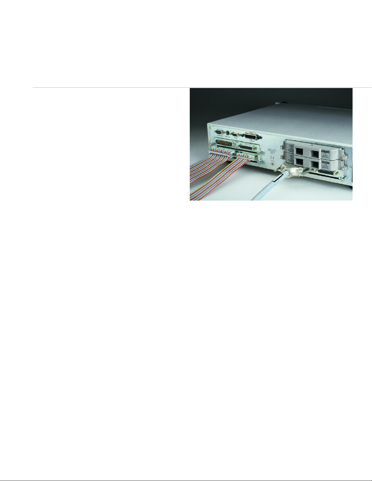
The Model 2750 supports nine different plug-in switch/control
modules, including those originally developed for the Model
2700 two-slot system. Any combination of five modules can
be installed at any time to match the test requirements. At
power-up, the mainframe automatically detects which modules
are installed, minimizing set-up time. To allow for timely
preventive maintenance for modules and enhance system uptime, the Model 2750 mainframe automatically logs the number
of relay closures on a memory chip built into each module.
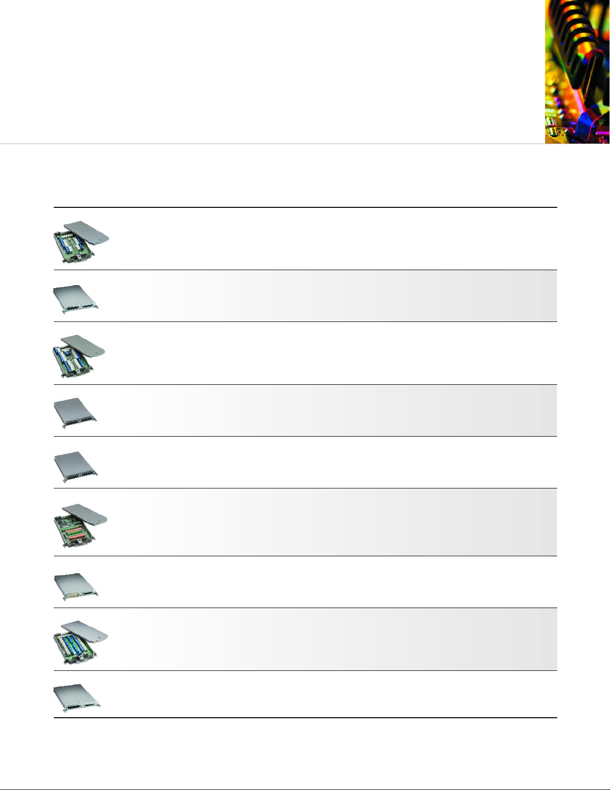
Model 7700 20-Channel Differential Multiplexer w/Automatic CJC
• 20 channels of general-purpose measurements, plus two
current measurement channels.
• 300V/1A capacity for voltage channels, 3A capacity for
current channels.
• Cold Junction Compensation sensors support temperature
measurements with thermocouples, RTDs, and thermistors.
Model 7701 Low Voltage 32-Channel Differential Multiplexer
• Configurable as 32 2-pole channels, 16 4-pole channels,
or as dual 1 × 16 independent multiplexers.
• 150V/1A capacity.
• D-sub/IDC ribbon cable connectors are standard.
Model 7702 40-Channel Differential Multiplexer
• 40 channels of general-purpose measurements, plus two
channels of current input.
• 300V/1A capacity for voltage channels, 3A capacity for current
channels.
• Oversize screw terminal blocks for easy wiring.
Model 7703 32-Channel High-Speed Differential Multiplexer
• Configurable as 32 2-pole channels, 16 4-pole channels, or as
dual 1 × 16 independent multiplexers.
• Reed relay design with <1ms relay actuation time allows fast
scanning.
• D-sub connectors for secure, reliable hookup.
Model 7705 40-Channel Control Module
• 40 independent control channels.
• Ideal for controlling power to the DUT, switching loads,
controlling light indicators and relays, etc.
• 300V/2A capacity.
Model 7706 All-in-One I/O Module
• 20 channels of analog input, 16 channels of digital output,
2 analog outputs.
• Automatic CJC supports thermocouple, RTD, and thermistor
temperature measurements.
• Event counter/totalizer for monitoring and controlling
systems components.
Model 7707 Multiplexer-Digital I/O Module
• 32 digital I/O channels (4 banks of 8).
• 10 differential analog input channels for
general-purpose measurements.
• D-sub connectors with IDC ribbon cable adapters.
Model 7708 40-Channel Differential Multiplexer w/Automatic CJC
• Dual 1 × 20 configuration.
• Direct thermocouple inputs with 1°C accuracy and 5°C
channel-to-channel variation.
• Designed especially for temperature datalogging and
burn-in applications.
Model 7709 6x8 Matrix Module
• 8 column ×6 row matrix can be daisy-chained to
create larger matrices.
• Automatic 2- or 4-wire connection to the internal DMM.
• 300V/1A capacity.
FLEXIBLE, FIVE-SLOT MAINFRAME
Switch/Control Modules
Our Growing Family of
Three connector alternatives simplify connecting the switch/control modules to
DUTs. Rugged D-sub connectors allow quick, secure connections and are especially
convenient when preforming routine maintenance or when the system is installed
in a rack. IDC ribbon cable adapters are supplied with the Model 7701, 7707, and
7709 modules for fast, uncomplicated hookups in production test and process
monitoring applications. Oversize screw-terminal connectors simplify setup in
applications that require the greatest connection flexibility. Additional D-sub and
IDC ribbon cable connector kits are sold separately.
Page 7
Max. Current
# Analog Type of Max. Switched Measurement Digital Switch
Module Inputs Configuration Differential*4-pole Connector Voltage Current Channels I/O Speed Other
7700
20 Multiplexer 1 × 20 or 1 × 10 Screw 300V 1A 2 channels N/A 3 ms Maximum power = 125VA.
w/CJC two 1 × 10 terminals @ 3A
7701
32 Multiplexer 1 × 32 or 1 × 16 D-sub 150V 1A N/A N/A 3 ms Maximum power = 125VA.
two 1 × 16
7702
40 Multiplexer 1 × 40 or 1 × 20 Screw 300V 1A 2 channels N/A 3 ms Maximum power = 125VA.
two 1 × 20 terminals @ 3A
7703
32 Multiplexer 1 × 32 or 1 × 16 D-sub 300V 500mA N/A N/A 1 ms Reed relays.
two 1 × 16
7705
40 Independent N/A N/A D-sub 300V 2A N/A N/A 3 ms Maximum power = 125VA.
SPST
7706
20 Multiplexer 1 × 20 or 1 × 10 Screw 300V 1A N/A 16 Digital 3 ms (2) ±12V analog output
w/CJC two 1 × 10 terminals Out Only channels & 100kHz event
counter/totalizer.
Maximum power = 125VA.
7707
10 Multiplexer/ 1 × 10 or 1 × 5 D-sub 300V 1A N/A 32 Digital 3 ms Maximum power = 125VA.
Digital I/O two 1 × 5 I/O (4) eight-bit word I/O.
7708
40 Multiplexer 1 × 40 or 1 × 20 Screw 300V 1A N/A N/A 3 ms Maximum power = 125VA.
w/CJC two 1 × 20 terminals
7709
48 6 × 8 Matrix Yes Yes D-sub 300V 1A N/A N/A 3 ms Connects to internal DMM.
Daisy chain multiple cards
for up to a 6 × 40 matrix.
Maximum power = 125VA.
*
Can be disconnected from internal DMM for routing external signals
Refer to the individual Switch/Control Module data sheets for additional information.
This selector guide may prove helpful in identifying the best module for a specific
application. Install up to five modules at a time in the Model 2750 mainframe.
Module Selector Guide
ACCURACY AND REPEATABILITY
Page 8
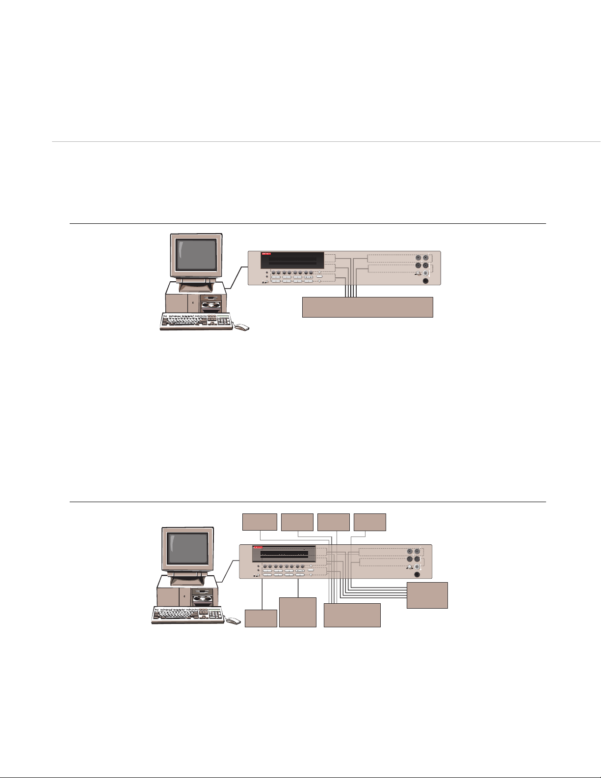
A variety of switch/control plug-in modules make it easy to
configure the Model 2750 for a broad range of test applications.
The application areas highlighted here are only the beginning—
consult a Keithley representative or system integrator partner for
assistance in determining the best combination of switch/control
modules to solve your next test challenge.
Temperature Chamber
EXIT ENTER
FILTER REL
DIGITS RATE
STORE RECALL
STEP SCAN
EX-TRIG TRIG
OPEN CLOSE
DCV ACV DCI ACI
Ω2 Ω4
FREQ TEMP
MODEL 2750 DATA ACQUISITION/CONTROL SYSTEM
RANGE
!
F
500V
PEAK
FRONT/REAR
2A 250V
AMPS
HI
INPUT
LO
SENSE
Ω 4 WIRE
INPUTS
350V
PEAK
1100V
PEAK
AUTO
PREV
NEXT
DISPLAY
POWER
RANGE
R
1234567891012345678910
EDIT ERR REMTALK LSTN SRQREAR REL FILTMATH 4W AUTO ARMTRIG SMPL
Model 2750
Applications
5-slot mainframe with internal 61⁄2-digit (22-bit) DMM.
Scan rates (switch/measure) of up to 200 channels/sec.
Relay cycle counting feature simplifies preventive maintenance.
Up to 200 differential channels or 248 matrix crosspoints.
Robust, industry-standard D-sub connectors. with solder cup or
IDC ribbon cable wiring
0.002% basic 90 day DCV accuracy: 1000V/300V input protection.
Rugged switch/control modules include matrix multiplex,
independent switch, digital I/O, analog output, and
counter/totalizer.
IEEE-488 interface and LabVIEW/LabWINDOWS CVI drivers
standard.
Fully functional front panel with input jacks for troubleshooting:
keypad and display for switch control and relay status.
EXIT ENTER
FILTER REL
DIGITS RATE
STORE RECALL
STEP SCAN
EX-TRIG TRIG
OPEN CLOSE
DCV ACV DCI ACI
Ω2 Ω4
FREQ TEMP
MODEL 2750 DATA ACQUISITION/CONTROL SYSTEM
RANGE
!
F
500V
PEAK
FRONT/REAR
2A 250V
AMPS
HI
INPUT
LO
SENSE
Ω 4 WIRE
INPUTS
350V
PEAK
1100V
PEAK
AUTO
PREV
NEXT
DISPLAY
POWER
RANGE
R
1234567891012345678910
EDIT ERR REMTALK LSTN SRQREAR REL FILTMATH 4W AUTO ARMTRIG SMPL
DUT loads
DUT
DUT
System
power
supplies
Oscilloscope Counter
Waveform
Generator
Power
Meter
Additional test instruments in ATE rack system
Directly measure up to 200 channels of voltage, temperature,
current, and/or resistance without signal conditioning or
external equipment.
Relay cycle counting feature simplifies preventive
maintenance.
110,000 point, non-volatile, dual-port memory buffer supports
automatic data backup; resumes scanning automatically in
case of a power failure.
Alarm limits per channel and master alarm output.
Analog and digital I/O for control.
300V isolation between channels and from any
channel to ground.
0.002% basic 90 day DCV accuracy; ±1°C thermocouple
accuracy.
Simple, secure cabling: D-sub, ribbon cable, or oversize
screw terminal blocks.
IEEE-488 and RS-232 communications bus.
Accelerated Stress Test (AST) Checklist
Production Test Checklist
Model 2750 with five modules
(3 x 7708, 7705, 7706)
Model 2750 with five modules
(7701, 7703, 7705, 7707, 7709)
EASY TO CONFIGURE
Page 9
EXIT ENTER
FILTER REL
DIGITS RATE
STORE RECALL
STEP SCAN
EX-TRIG TRIG
OPEN CLOSE
DCV ACV DCI ACI
Ω2 Ω4
FREQ TEMP
MODEL 2750 DATA ACQUISITION/CONTROL SYSTEM
RANGE
!
F
500V
PEAK
FRONT/REAR
2A 250V
AMPS
HI
INPUT
LO
SENSE
Ω 4 WIRE
INPUTS
350V
PEAK
1100V
PEAK
AUTO
PREV
NEXT
DISPLAY
POWER
RANGE
R
1234567891012345678910
EDIT ERR REMTALK LSTN SRQREAR REL FILTMATH 4W AUTO ARMTRIG SMPL
Kelvin
Shunts
Optional
Power Supply/
Model 2400
Misc.
Instruments
control
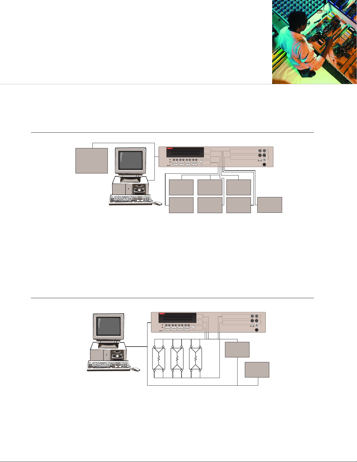
DUT #1, #2 –100
Low noise offset compensation.
10mA current minimizes relay non-linearities.
20mV dry circuit clamp.
100-channel Kelvin 4-wire switch capacity.
Mixed signal capabilities
Offset compensation/cancellation of thermoelectric EMFs.
1µΩ sensitivity covers most low ohms applications.
Process Monitoring and Control Checklist
Multi-channel Low Ohms Testing Checklist
EXIT ENTER
FILTER REL
DIGITS RATE
STORE RECALL
STEP SCAN
EX-TRIG TRIG
OPEN CLOSE
DCV ACV DCI ACI
Ω2 Ω4
FREQ TEMP
MODEL 2750 DATA ACQUISITION/CONTROL SYSTEM
RANGE
!
F
500V
PEAK
FRONT/REAR
2A 250V
AMPS
HI
INPUT
LO
SENSE
Ω 4 WIRE
INPUTS
350V
PEAK
1100V
PEAK
AUTO
PREV
NEXT
DISPLAY
POWER
RANGE
R
1234567891012345678910
EDIT ERR REMTALK LSTN SRQREAR REL FILTMATH 4W AUTO ARMTRIG SMPL
4-20mA,
0-10V Inputs
System
Controller
or
Electronic
Sensors
Temperature,
Pressure
Pump, Valves,
Solenoids
Fans, Blowers,
Motors
Limit Switches,
Alarms
Power Routing
Machine
Control
Model 2750 with five modules
(7701, 7707, 7705, 7708, 7706)
Model 2750 with five modules
A BROAD RANGE OF APPLICATIONS
Up to 200 channels of differential analog I/O.
Up to 160 channels of digital I/O.
6
1
⁄
2
-digit (22-bit) resolution with 0.002% basic 90 day
DCV accuracy.
Built-in signal conditioning and 1000V/300V isolation.
Flexible, modular configuration.
Per-channel configurability, scaling, and alarm limits.
Rugged packaging including industry-standard D-sub connectors
and interface to PB-24SM board.
Front panel input jacks simplify troubleshooting.
Directly measure voltage, temperature, current, resistance, sensors,
and transducers without signal conditioning.
RS-232 and GPIB communications standard.
Page 10

DC MEASUREMENT SPEEDS
15
Single Channel, 60Hz (50Hz) Operation
FUNCTION DIGITS READINGS/s PLCs
DCV, DCI, Ω (<10M), 6.5
12,16
5(4) 10
Thermocouple, 6.5
16
35 (28) 1
Thermistor 6.5
12,16
45 (36) 1
5.5
12,16
150 (120) 0.1
5.5
16, 17
300 (240) 0.1
5.5
17
480 (400) 0.1
4.5
17
2500 (2000) 0.01
4WΩ (<10M) 6.5
16
1.4 (1.1) 10
6.5
16
15 (12) 1
5.5
17
33 (25) 0.1
Channel (Ratio), 6.5
16
2.5 (2) 10
Channel (AVG) 6.5
16
15 (12) 1
5.5
17
25 (20) 0.1
Multiple Channels, Into and Out of Memory to GPIB
15,18
Channels/s
7703 Scanning DCV 200/s
7703 Scanning DCV with Limits or Time Stamp On 180/s
7703 Scanning DCV alternating 2W 70/s
7702 Scanning DCV 65/s
7700, 7706, and 7708 Scanning Temperature (T/C) 50/s
DC MEASUREMENT CHARACTERISTICS
DC Volts
A-D LINEARITY: 2.0 ppm of reading + 1.0 ppm of range.
INPUT IMPEDANCE:
100mV–10V Ranges: Selectable >10GΩ // with <400pF or 10MΩ ±1%.
100V, 1000V Ranges: 10MΩ ±1%.
Dry Circuit: 100kΩ ± 1% // <1µF.
INPUT BIAS CURRENT: <75pA at 23°C.
COMMON MODE CURRENT: <500nApp at 50Hz or 60Hz.
AUTOZERO ERROR: Add ±(2ppm of range error + 5µV) for < 10 minutes and ±1°C.
INPUT PROTECTION: 1000V, all ranges. 300V with plug in modules.
Resistance
MAX 4WΩ LEAD RESISTANCE: 80% of range per lead (Dry Ckt mode). 5Ω per lead for 1Ω
range; 10% of range per lead for 10Ω, 100Ω, and 1kΩ ranges; 1kΩ per lead for all other ranges.
OFFSET COMPENSATION: Selectable on 4WΩ, 1Ω, 10Ω, 100Ω, 1kΩ, and 10kΩ ranges.
CONTINUITY THRESHOLD: Adjustable 1 to 1000 Ω
INPUT PROTECTION: 1000V, all Source Inputs, 350V Sense Inputs. 300V with plug-in modules.
DC Current
SHUNT RESISTORS: 100mA–3A, 0.1Ω. 20mA, 5Ω.
INPUT PROTECTION: 3A, 250V fuse.
DC SYSTEM SPEEDS
15,18
RANGE CHANGES16: 90/s (72/s).
FUNCTION CHANGES
16
: 90/s (72/s).
AUTORANGE TIME
16
: <60ms.
ASCII READINGS TO RS-232 (19.2k BAUD): 55/s.
MAX. INTERNAL TRIGGER RATE: 2000/s.
MAX. EXTERNAL TRIGGER RATE: 375/s.
Model 2750
Specifications
DC CHARACTERISTICS
1
CONDITIONS: MED (1 PLC)2or 10 PLC or MED (1 PLC) with Digital Filter of 10
TEST INPUT
ACCURACY: ±(ppm of reading + ppm of range)
CURRENT ±5% RESISTANCE
(ppm = parts per million) (e.g., 10ppm = 0.001%)
TEMPERATURE
OR BURDEN OR OPEN CKT. 24 Hour
4
90 Day 1 Year COEFFICIENT
FUNCTION RANGE RESOLUTION VOLTAGE VOLTAGE
3
23°C±1° 23°C±5° 23°C±5° 0°–18°C & 28°–50°C
Voltage
11
100.0000 mV 0.1 µV >10 GΩ 15 + 30 25 + 35 30 + 35 (1 + 5)/°C
1.000000 V 1.0 µV >10 GΩ 15 + 6 25 + 7 30 + 7 (1 + 1)/°C
10.00000 V 10 µV >10 GΩ 10 + 4 20 + 5 30 + 5 (1 + 1)/°C
100.0000 V 100 µV 10 MΩ ± 1% 15 + 6 35 + 9 45 + 9 (5 + 1)/°C
1000.000 V
5
1mV 10MΩ ± 1% 20 + 6 35 + 9 50 + 9 (5 + 1)/°C
Resistance
6, 8
1.000000 Ω 1µΩ 10 mA 5.9 V 25 + 80 80 + 80 100 + 80 (8 + 1)/°C
10.00000 Ω 10 µΩ 10 mA 5.9 V 20 + 20 80 + 20 100 + 20 (8 + 1)/°C
100.0000 Ω 100 µΩ 1 mA 12.2 V 20 + 20 80 + 20 100 + 20 (8 + 1)/°C
1.000000 kΩ 1mΩ 1 mA 12.2 V 20 + 6 80 + 6 100 + 6 (8 + 1)/°C
10.00000 kΩ 10 mΩ 100 µA 6.8 V 20 + 6 80 + 6 100 + 6 (8 + 1)/°C
100.0000 kΩ 100 mΩ 10 µA 12.8 V 20 + 6 80 + 10 100 + 10 (8 + 1)/°C
1.000000 MΩ
23
1.0 Ω 10 µA 12.8 V 20 + 6 80 + 10 100 + 10 (8 + 1)/°C
10.00000 MΩ
7, 23
10 Ω 0.7 µA // 10M Ω 7.0 V 150 + 6 200 + 10 400 + 10 (35 + 1)/°C
100.0000 MΩ
7, 23
100 Ω 0.7 µA // 10M Ω 7.0 V 800 + 30 2000 + 30 2000 + 30 (200 + 1)/°C
Dry Circuit 1.000000 Ω 1µΩ 10 mA 20mV 30 + 40 80 + 40 100 + 40 (8 + 1)/°C
Resistance
21
10.00000 Ω 10 µΩ 1 mA 20mV 25 + 40 80 + 40 100 + 40 (8 + 1)/°C
100.0000 Ω 100 µΩ 100 µA 20mV 25 + 40 90 + 40 140 + 40 (8 + 1)/°C
1.000000 kΩ 1mΩ 10 µA 20mV 25 + 90 180 + 90 400 + 90 (8 + 1)/°C
Continuity (2W) 1.000 kΩ 100 mΩ 1 mA 12.2 V 40 + 100 100 + 100 100 + 100 (8 + 1)/°C
Current 20.00000 mA 10 nA < 0.2 V 60 + 15 300 + 40 500 + 40 (50 +5)/°C
100.0000 mA 100 nA < 0.1 V 100 + 150 300 + 400 500 + 400 (50 +50)/°C
1.000000 A 1.0 µA < 0.3 V
9
200 + 15 500 + 40 800 + 40 (50 +5)/°C
3.000000 A 10 µA < 1.0 V
9
1000 + 15 1200 + 40 1200 + 40 (50 +5)/°C
Channel (Ratio)
10
Ratio Accuracy = Accuracy of selected Channel Range + Accuracy of Paired Channel Range
Channel (Average)
10
Average Accuracy = Accuracy of selected Channel Range + Accuracy of Paired Channel Range
DUAL-PORT MEMORY BUFFER
Page 11

GENERAL SPECIFICATIONS
MEMORY:
Memory Size: 110,000 readings.
EXPANSION SLOTS: 5.
POWER SUPPLY: 100V / 120V / 220V / 240V ±10%.
LINE FREQUENCY: 45Hz to 66Hz and 360Hz to 440Hz, automatically sensed
at power-up.
POWER CONSUMPTION: 28VA.
BATTERY: Lithium battery-backed memory, 3 years @ 23°C.
WARRANTY: 3 years.
EMC: Conforms to European Union Directive 89/336/EEC EN61326-1.
SAFETY: Conforms to European Union Directive 73/23/EEC EN61010-1, CAT I.
OPERATING ENVIRONMENT: Specified for 0°C to 50°C. Specified to 80% RH
at 35°C.
DIMENSIONS:
Rack Mounting: 89mm high × 485mm wide × 370mm deep (3.5 in × 19 in ×
14.563 in).
Bench Configuration (with handle and feet): 104mm high × 238mm wide
× 370mm deep (4.125 in × 9.375 in × 14.563 in).
SHIPPING WEIGHT: 13kg (28 lbs.).
ACCESSORIES SUPPLIED: Model 1751 Safety Test Leads, User Manual, Service
Manual.
TEMPERATURE
1
(Displayed in °C, °F, or K. Exclusive of probe errors.)
Thermocouples (Accuracy based on ITS-90.)
90 Day/1 Year (23°C ± 5°C)
Relative to Using CJC Temperature
Simulated from Plug-In Coefficient
Type Range Resolution Reference Junction Module 0°–18°C & 28°–50°C
J –200 to +760 °C 0.001 °C 0.2°C 1.0°C 0.03°C/°C
K –200 to +1372°C 0.001 °C 0.2°C 1.0°C 0.03°C/°C
N –200 to +1300°C 0.001 °C 0.2°C 1.0°C 0.03°C/°C
T –200 to +400°C 0.001 °C 0.2°C 1.0°C 0.03°C/°C
E –200 to +1000°C 0.001 °C 0.2°C 1.0°C 0.03°C/°C
R 0 to +1768°C 0.1 °C 0.6°C 1.8°C 0.03°C/°C
S 0 to +1768°C 0.1 °C 0.6°C 1.8°C 0.03°C/°C
B +350 to +1820°C 0.1 °C 0.6°C 1.8°C 0.03°C/°C
4-Wire RTD:
(100Ω platinum [PT100], D100, F100, PT385, PT3916, or user type. Offset compensation On)
–200° to 630°C 0.01 °C 0.06°C 0.003°C/°C
Thermistor: (2.2kΩ, 5kΩ, and 10kΩ)
20
–80° to 150°C 0.01 °C 0.08°C 0.002°C/°C
AC MEASUREMENT SPEEDS
7
Single Channel, 60Hz (50Hz) Operation
Function Digits Readings/s Rate Bandwidth
ACV, ACI 6.5
8
2s/Reading SLOW 3 Hz–300 kHz
6.5
8
1.4 (1.1) MED 30 Hz–300 kHz
6.5
9
4.8 (4) MED 30 Hz–300 kHz
6.5
9
35 (28) FAST 300 Hz–300 kHz
Frequency, 6.5 1 (1) SLOW 3 Hz–300 kHz
Period 5.5 9 (9) MED 30 Hz–300 kHz
4.5 35 (35) FAST 300 Hz–300 kHz
4.5
10
65 (65) FAST 300 Hz–300 kHz
Multiple Channel
7703 SCANNING ACV
10, 13
: 180/s.
AC MEASUREMENT CHARACTERISTICS
AC Volts
MEASUREMENT METHOD: AC-coupled, True RMS.
INPUT IMPEDANCE: 1MΩ ±2% // by <100pF.
INPUT PROTECTION: 1000Vp or 400VDC. 300Vrms with plug in modules.
AC Current
MEASUREMENT METHOD: AC-coupled, True RMS.
SHUNT RESISTANCE: 0.1Ω.
BURDEN VOLTAGE: 1A <0.3Vrms, 3A <1.5Vrms. Add 1Vrms when used with plug in
modules.
INPUT PROTECTION: 3A, 250V fuse.
Frequency and Period
MEASUREMENT METHOD: Reciprocal Counting technique.
GATE TIME: SLOW 1s, MED 100ms, and FAST 10ms.
AC SYSTEM SPEEDS
7, 11
RANGE CHANGES12: 4/s (3/s).
FUNCTION CHANGES
12
: 4/s (3/s).
AUTORANGE TIME: < 3s.
ASCII READINGS TO RS-232 (19.2k baud): 50/s.
MAX. INTERNAL TRIGGER RATE: 300/s.
MAX. EXTERNAL TRIGGER RATE: 250/s.
AC SPECIFICATIONS
1
Accuracy: ±(% of reading + % of range), 23°C ± 5°C
Calibration 3 Hz– 10 Hz– 20 kHz– 50 kHz– 100 kHz–
Function Range Resolution Cycle 10 Hz 20 kHz 50 kHz 100 kHz 300 kHz
Voltage
2
100.0000 mV 0.1 µV 90 Days 0.35 + 0.03 0.05 + 0.03 0.11 + 0.05 0.6 + 0.08 4.0 + 0.5
1.000000 V 1.0 µV
10.00000 V 10 µV 1 Year 0.35 + 0.03 0.06 + 0.03 0.12 + 0.05 0.6 + 0.08 4.0 + 0.5
100.0000 V 100 µV
750.000 V 1.0 µV
(Temp. Coeff.)/°C
3
0.035 + .003 0.005 + .003 0.006 + .005 0.01 + .006 0.03 + .01
3 Hz–10 Hz 10 Hz–5 kHz
Current
2
1.000000 A 1.0 µA 90 Day/1 Yr. 0.30 + 0.04 0.10 + 0.04
3.00000 A
14
10 µA 0.35 + 0.06 0.15 + 0.06
(Temp. Coeff.)/°C
3
0.035 + 0.006 0.015 + 0.006
(3 Hz–500 kHz) (333 ms–2 µs)
Frequency
4
100 mV 0.333ppm 90 Day/ 1 Yr. 100 ppm + 0.333 ppm (SLOW, 1s gate)
and Period to 3.33ppm 100 ppm + 3.33 ppm (MED, 100ms gate)
750 V 33.3 ppm 100 ppm + 33.3 ppm (FAST, 10ms gate)
MIXED SIGNAL CAPABILITIES
Page 12

While the Model 2750 offers
the capacity needed to handle
high-channel-count testing, many
applications require just 80 switching or control channels or
less. For these cases, the two-slot Model 2700 Multimeter/Data
Acquisition system is often the perfect size. Built on the same
measurement platform, the Model 2700 and Model 2750 share
many of the same capabilities and programming commands. All
the switch/control modules work in both mainframes. This high
compatibility also makes it easy to migrate applications from the
Model 2700 to the Model 2750 as new test needs emerge or the
number of test points grows.
Matrix or Multiplexer
A matrix switch is the most versatile type of
system switching—any input can be connected to
output, singly or in combination. A multiplex
switch connects one instrument to multiple
devices under test or multiple instruments to
one device under test. To find out more:
To request a FREE copy of
Keithley’s Switching Handbook,
visit www.keithley.com
With more than a half-century of expertise in making
demanding low-level measurements, Keithley offers its
customers a greater measure of testing confidence on the
production floor, in the QA lab, and in R&D. For more
information on how Keithley test solutions can help you
keep pace with changing technologies, call your local
Keithley sales engineer or visit our website.
For applications assistance, call us on our toll-free hotline
1-888-KEITHLEY (534-8453) from 8:00 am to 5:00 pm ET (U.S.
only). If you need assistance beyond those hours, send our
Applications Engineering Department a facsimile (440-248-6168) or
an e-mail message ([email protected]) and we’ll respond
as soon as possible. Applications assistance is also available via the
web, with many reference materials available online, as well as
convenient forms for contacting our Applications Engineers.
Keithley maintains facilities and affiliates worldwide, which offer
native language support services. Visit our web site for the latest
listings
.
www.keithley.com
A Greater Measure of Confidence All the Support You Need
Keithley’s two-slot solution for
smaller applications
Specifications are subject to change without notice.
All Keithley trademarks and trade names are the property of Keithley Instruments, Inc.
All other trademarks and trade names are the property of their respective companies.
Keithley Instruments, Inc. 28775 Aurora Road • Cleveland, Ohio 44139 • 440-248-0400 • Fax: 440-248-6168
1-888-KEITHLEY (534-8453) www.keithley.com
BELGIUM: Keithley Instruments B.V. Bergensesteenweg 709 • B-1600 Sint-Pieters-Leeuw • 02-363 00 40 • Fax: 02/363 00 64
CHINA: Keithley Instruments China Yuan Chen Xin Building, Room 705 • 12 Yumin Road, Dewai, Madian • Beijing 100029 • 8610-6202-2886 • Fax: 8610-6202-2892
FRANCE: Keithley Instruments Sarl 3, allée des Garays • 91127 Palaiseau Cédex • 01-64 53 20 20 • Fax: 01-60 11 77 26
GERMANY: Keithley Instruments GmbH Landsberger Strasse 65 • 82110 Germering • 089/84 93 07-40 • Fax: 089/84 93 07-34
GREAT BRITAIN: Keithley Instruments Ltd. Unit 2 Commerce Park, Brunel Road • Theale, Berkshire RG7 4AB • Phone: 0118-9 57 56 66 • Fax: 0118-9 59 64 69
INDIA: Keithley Instruments GmbH Flat 2B, WILLOCRISSA • 14, Rest House Crescent • Bangalore 560 001 • 91-80-509-1320/21 • Fax: 91-80-509-1322
ITALY: Keithley Instruments s.r.l. Viale San Gimignano, 38 • 20146 Milano • 02-48 39 16 01 • Fax: 02-48 30 22 74
KOREA: Keithley Instruments Korea 2FL., URI Building • 2-14 Yangjae-Dong • Seocho-Gu, Seoul 137-130 • 82-2-574-7778 • Fax: 82-2-574-7838
NETHERLANDS: Keithley Instruments B.V. Postbus 559 • 4200 AN Gorinchem • 0183-635333 • Fax: 0183-630821
SWITZERLAND: Keithley Instruments SA Kriesbachstrasse 4 • 8600 Dübendorf • 01-821 94 44 • Fax: 01-820 30 81
TAIWAN: Keithley Instruments Taiwan 1FL., 85 Po Ai Street • Hsinchu, Taiwan, R.O.C. • 886-3-572-9077• Fax: 886-3-572-9031
© Copyright 2001 Keithley Instruments, Inc. No. 2293
Printed in the U.S.A. 20160KCG
 Loading...