

Page 1
T
ECHNICAL DATA
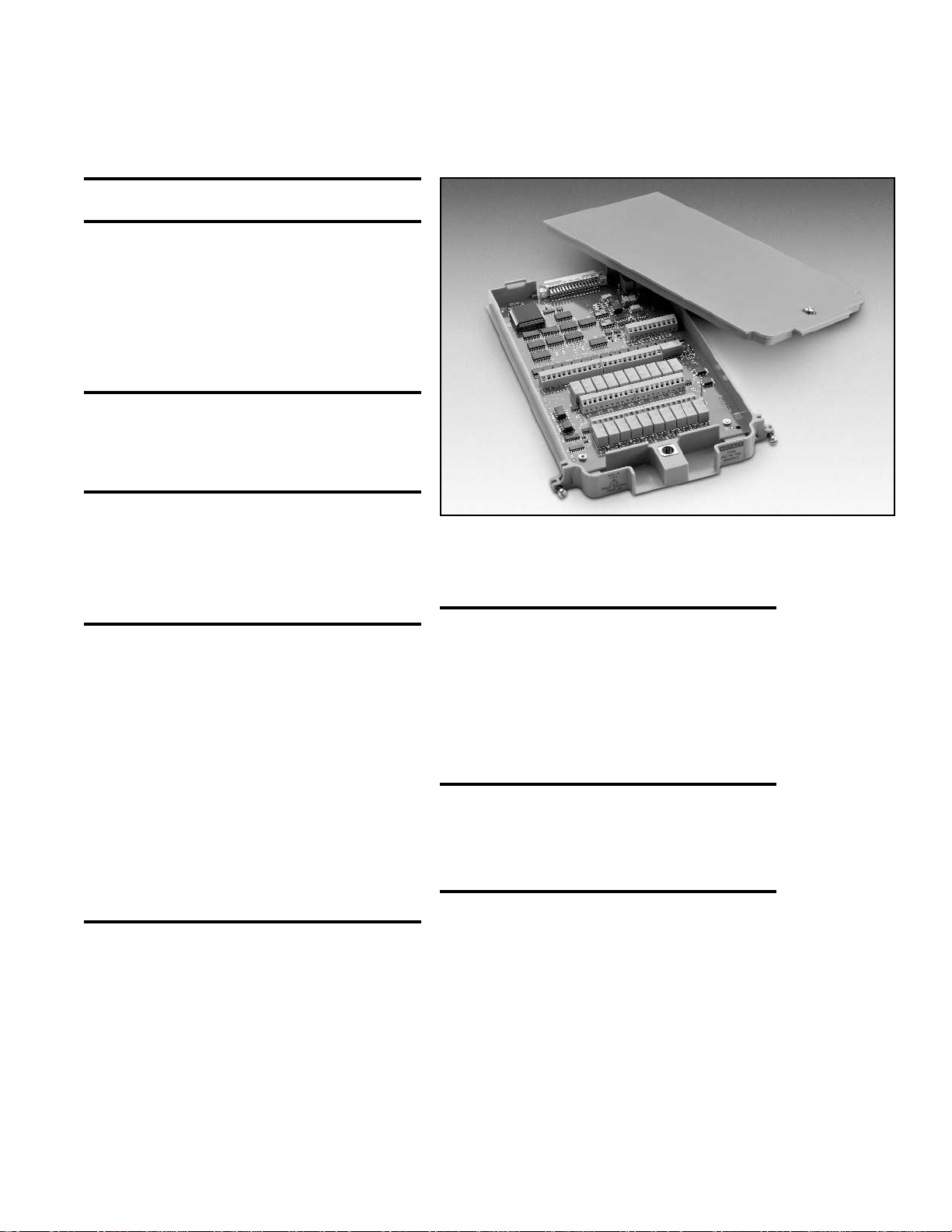
Model 7706 All-in-One I/O Module
Features
• 20 channels of analog input (w/ automatic CJC) for general-purpose
measurement.
• 16 channels of digital output for I/O control.
• Event counter/totalizer can monitor and control system components,
such as fixturing, limit switches, pass/fail indicators, external voltage
sources, loads, door closures, revolutions, etc., while performing mixed
signal measurement.
• 300V, 1A capacity; 60W, 125VA maximum.
• Two analog outputs (±12V, 5mA).
GENERAL
20 CHANNELS: 20 channels of 2-pole relay input.
All channels configurable to 4-pole.
RELAY TYPE: Latching electromechanical.
ACTUATION TIME: <3ms.
CAPABILITIES
CHANNELS 1–20: Multiplex one of 20 2-pole or one of 10 4-pole signals
into DMM.
Channels 21–25 are referenced to chassis ground.
CHANNELS 21–22: 16 Digital Outputs.
CHANNELS 23–24: Analog Voltage Output (2).
CHANNELS 25: Totalize Input.
INPUTS
MAXIMUM SIGNAL LEVEL (Channels 1–20): 300V DC or rms, 1A
switched, 60W, 125VA maximum.
CONTACT LIFE (typ.): >10
5
operations at max. signal level: >108opera-
tions cold switching.
CONTACT RESISTANCE: <1Ω at end of contact life.
CONTACT POTENTIAL: <±500nV typical per contact, 1µV max.
<±500nV typical per contact pair, 1µV max.
OFFSET CURRENT: <100pA.
CONNECTOR TYPE: Screw terminal, #20 AWG wire size.
ISOLATION BETWEEN ANY TWO TERMINALS: >10
9
Ω, <100pF.
ISOLATION BETWEEN ANY TERMINAL AND EARTH: > 10
9
Ω, <200pF.
CROSS TALK (10MHz, 50ΩLoad): <–40dB.
INSERTION LOSS (50ΩSource, 50ΩLoad): <0.1dB below 1MHz.
<3dB below 2Mhz.
COMMON MODE VOLTAGE: 300V between any terminal and chassis.
T/C COLD JUNCTION: 1.0°C (18°C to 28°C mainframe temp.).
1.5°C (0°–18°C & 28°–50°C mainframe temp.).
TOTALIZE INPUT
MAXIMUM COUNT: 232–1.
TOTALIZE INPUT: 100kHz (max), rising or falling edge, programmable.
SIGNAL LEVEL: 1Vp-p (min), 42Vpk (max).
THRESHOLD: 0V or TTL, jumper selectable.
DATE INPUT: TTL-Hi, TTL-Lo, or none.
COUNT RESET: manual or Read+Reset.
READ SPEED: 10/s.
S WITCH/CONTROL M ODULE S PECIFICATIONS
ANALOG VOLTAGE OUTPUT
DAC 1, 2: ±Non-isolated.
RESOLUTION: 1mV.
I
OUT
: 5mA max.
SETTLING TIME: 1ms to 0.01% of output.
ACCURACY ±(% of output + mV):
1 year ±5°C: 0.15% + 6mV;
90 day ±5°C: 0.1% + 6mV;
24 hour ±1°C: 0.04% + 4mV.
TEMPERATURE COEFFICIENT: ±(0.015% + 1mV)/°C.
DIGITAL OUTPUT
V
OUT
(L): <0.8V @ Iout = 400mA.
V
OUT
(H): >2.4V @ Iout = 1mA.
V
OUT
(H)MAX.: <42V with external open drain pull-up.
WRITE SPEED: 10/s.
ENVIRONMENTAL
OPERATING ENVIRONMENT: Specified for 0°C to 50°C.
Specified to 80% R.H. at 35°C.
STORAGE ENVIRONMENT: –25°C to 65°C.
WEIGHT: 0.5kg (1.1 lbs).
Page 2
M
ODEL 2700 M ULTIMETER
/DATA A CQUISITION S YSTEM
S WITCH/CONTROL M ODULE S PECIFICATIONS
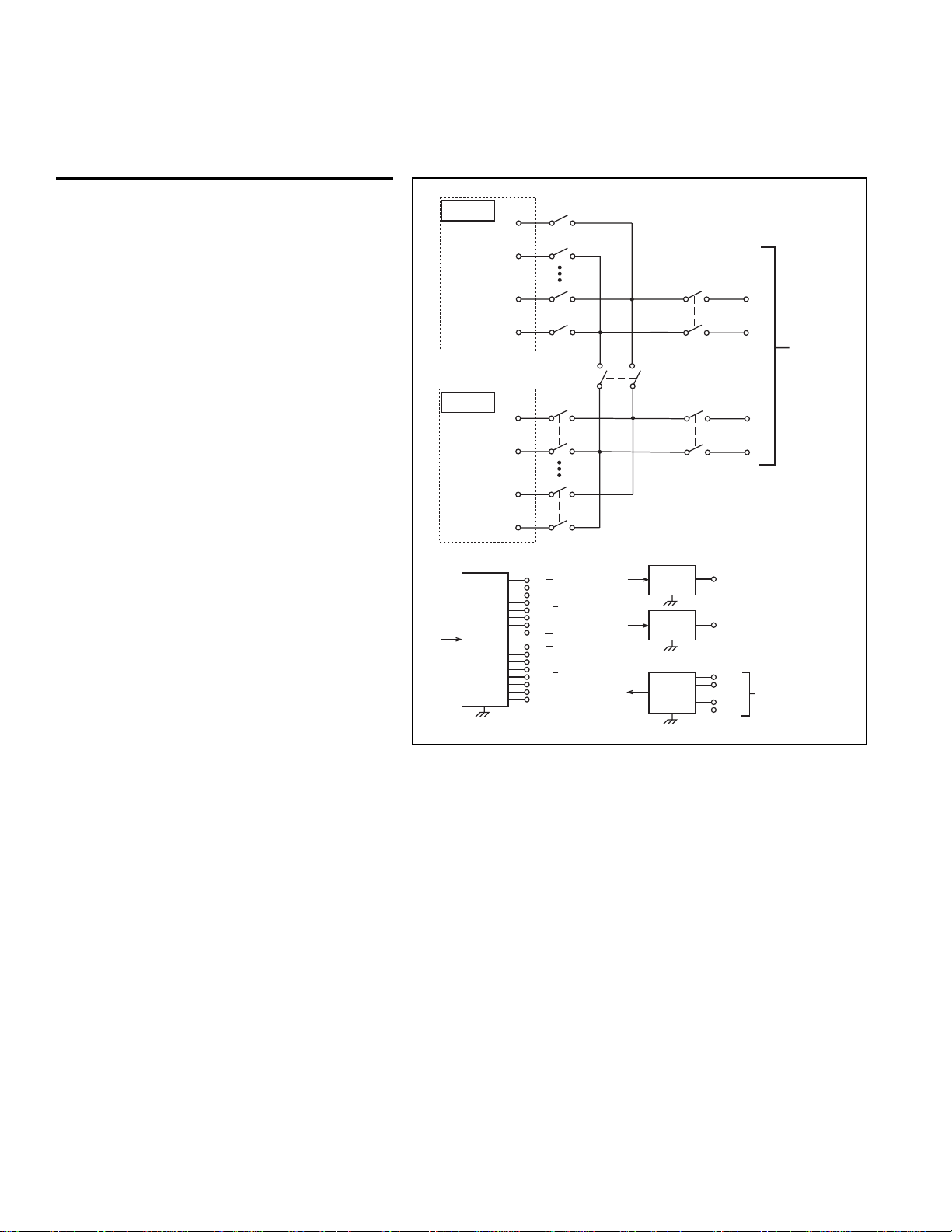
Model 7706 All-in-One I/O Module (cont.)
Cold junction
Ref x3
Channel 1
(Channels 2–9)
Channel 10
Cold junction
Ref x3
Channel 11
(Channels 12–19)
Channel 20
Digital I/O
16
DIO
HI
LO
HI
LO
Channel 26
2-Pole / 4-Pole
(see Note)
HI
LO
HI
LO
Bit
0
1
2
3
Channel 21
4
5
6
7
0
1
2
3
Channel 22
4
5
6
7
Channel 28
(see Note)
Backplane
isolation
HI
Input
LO
Channel 27
(see Note)
Backplane
isolation
NOTE Channels 26–28 in this schematic
refer to the designations used for
control and not actual available channels.
For more information, refer to the
ROUTE:MULT command section
in the Model 2700 User’s Manual.
Analog Output
16
DAC 1
16
DAC 2
Totalizer
32
TOT
Sense
Channel 23
Channel 24
+IN
–IN
+GATE
–GATE
HI
LO
Channel 25
To Model 2700
Backplane
 Loading...