

Page 1

Keithley Instruments, Inc.
28775 Aurora Road
Cleveland, Ohio 44139
1-888-KEITHLEY
www.keithley.com
Analog Backplane Extender
Model 3706-BKPL
Introduction
The Keithley Instruments Model 3706-BKPL Analog Backplane Extender allows external
analog signal connections directly to the Model 3706 backplane. This is useful as a DMM
calibration input and for external instruments such as the Series 2600 System
SourceMeter™, function generators, and counters, as well as to daisy-chain additional Model
3700s in series.
This instruction sheet contains information about features, terminal block wiring, and
installation and removal of the Model 3706-BKPL.
WARNING The following information is intended for qualified service
personnel. Do not make connections unless qualified to do so.
To prevent electric shock that could result in serious injury or
death, observe the following safety procedures:
• Before removing or installing the Analog Backplane
Extender on the mainframe, make sure the mainframe is
turned off and disconnected from power.
• Before making or breaking connections, make sure power is
removed from all external circuitry.
• Do not connect signals that may exceed the maximum
specifications of the model or external wiring.
• All wiring must be rated for the maximum voltage in the
system. For example, if 300V is applied to the backplane
extender, all module wiring must be rated for 300V.
Maximum Signal Levels
Input: DMM-HI / LO, DMM-SHI / SLO, and A3-HI / LO through A6-HI / LO: 300V DC or
300V RMS (425V peak for AC waveforms) 3A, 60W, 125V between any terminal to
terminal or terminal to chassis.
Input: AMP and AMP-LO: 3ADC or 3A RMS (4.25A peak for AC waveforms), 250V
peak between terminals or terminals to chassis.
CAUTION The analog backplane extender is rated for connections to circuits rated
for Category I only, with transients rated less than 1500V peak. Do not
connect to CAT II, CAT III, or CAT IV circuits. Connections to circuits
higher than CAT I can cause damage to the equipment or expose the
operator to hazardous voltages.
PA-964 Rev. A / December 2007 1
Page 2
Model 3706-BKPL Analog Backplane Extender
Figure 1 shows a top-down view of the circuit board for the Model 3706-BKPL.
Figure 1
Model 3706-BKPL Analog Backplane Extender
Mounting
screws
2 PA-964 Rev. A / December 2007
Page 3

Model 3706-BKPL Analog Backplane Extender
Example circuit board terminal block wiring
It is not necessary to remove the circuit board from the bottom cover to wire the analog
backplane extender.
CAUTION Avoid handling circuit board surfaces and terminal blocks. Contaminants
from hands may degrade analog backplane extender performance.
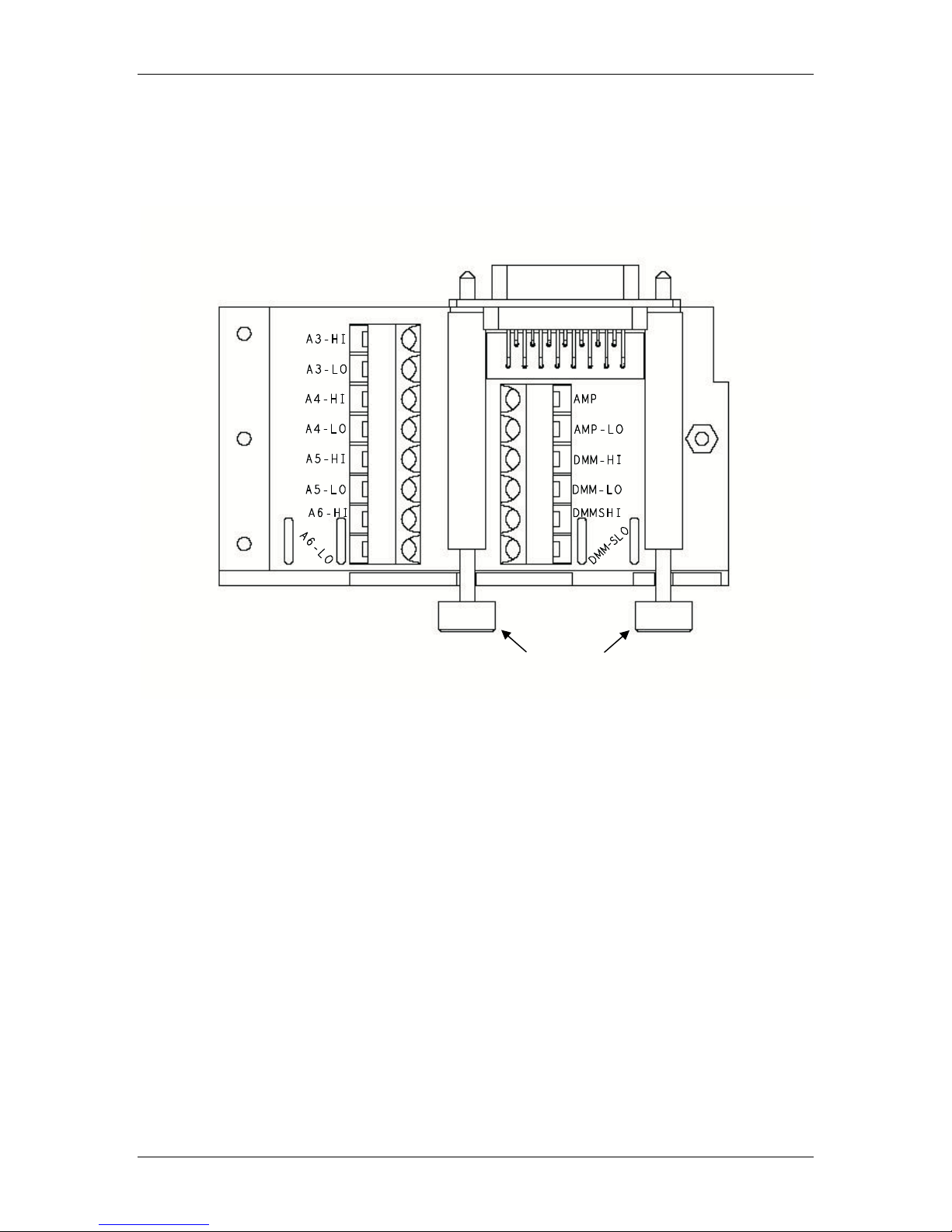
Figure 2 shows how to wire the Analog Backplane Extender and where to use cable ties for
cable strain relief.
Figure 2
Example of routing and securing cables with ties
NOTE Terminals and strain relief rated for #24 through #16 AWG wire sizes.
PA-964 Rev. A / December 2007 3
Cable tieCable tie
Page 4
Model 3706-BKPL Analog Backplane Extender
Installation and removal instructions
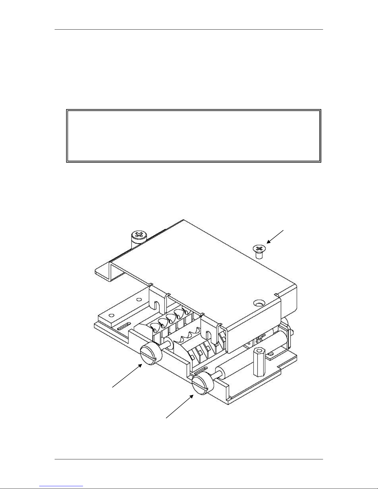
Figures 3 and 4 show how to install the top cover on a circuit board and how to install the
analog backplane extender.
Reverse the installation process to remove the Model 3706-BKPL. For example, start with
Figure 4 and follow the instructions in reverse.
WARNING Before powering-up the Series 3700 after installing the Model
3706-BKPL, verify that the analog backplane extender is properly
installed and the mounting screws are tightly fastened. If the
mounting screws are not properly secured, an electrical shock
hazard may be present.
Figure 3
Installation of top cover and location of mounting screws
Top cover
mounting
screw
Mounting Screws
(slotted for screwdriver)
4 PA-964 Rev. A / December 2007
Page 5

Model 3706-BKPL Analog Backplane Extender
Figure 4
Analog backplane extender installation to the Series 3700
CAUTION DO NOT OVER-TIGHTEN THE MOUNTING SCREWS! Over-tightening
will damage the extender.
PA-964 Rev. A / December 2007 5
 Loading...