

Page 1

www.keithley.com
Series 3700 System Switch/Multimeter
Quick Start Guide
3700S-903-01 Rev. A / August 2007
3700S-903-01.qxd 8/10/07 3:27 PM Page 1
Page 2

WARRANTY
Keithley Instruments, Inc. warrants this product to be free from defects in material and workmanship for a period of
one (1) year from date of shipment.
Keithley Instruments, Inc. warrants the following items for 90 days from the date of shipment: probes, cables,
software, rechargeable batteries, diskettes, and documentation.
During the warranty period, Keithley Instruments will, at its option, either repair or replace any product that proves
to be defective.
To exercise this warranty, write or call your local Keithley Instruments representative, or contact
Keithley Instruments headquarters in Cleveland, Ohio. You will be given prompt assistance and return instructions.
Send the product, transportation prepaid, to the indicated service facility. Repairs will be made and the product
returned, transportation prepaid. Repaired or replaced products are warranted for the balance of the original
warranty period, or at least 90 days.
LIMITATION OF WARRANTY
This warranty does not apply to defects resulting from product modification without Keithley Instruments’ express
written consent, or misuse of any product or part. This warranty also does not apply to fuses, software,
non-rechargeable batteries, damage from battery leakage, or problems arising from normal wear or failure to follow
instructions.
THIS WARRANTY IS IN LIEU OF ALL OTHER WARRANTIES, EXPRESSED OR IMPLIED, INCLUDING ANY
IMPLIED WARRANTY OF MERCHANTABILITY OR FITNESS FOR A PARTICULAR USE. THE REMEDIES
PROVIDED HEREIN ARE BUYER’S SOLE AND EXCLUSIVE REMEDIES.
NEITHER KEITHLEY INSTRUMENTS, INC. NOR ANY OF ITS EMPLOYEES SHALL BE LIABLE FOR ANY
DIRECT, INDIRECT, SPECIAL, INCIDENTAL, OR CONSEQUENTIAL DAMAGES ARISING OUT OF THE USE
OF ITS INSTRUMENTS AND SOFTWARE, EVEN IF KEITHLEY INSTRUMENTS, INC. HAS BEEN ADVISED IN
ADVANCE OF THE POSSIBILITY OF SUCH DAMAGES. SUCH EXCLUDED DAMAGES SHALL INCLUDE, BUT
ARE NOT LIMITED TO: COST OF REMOVAL AND INSTALLATION, LOSSES SUSTAINED AS THE RESULT OF
INJURY TO ANY PERSON, OR DAMAGE TO PROPERTY.
A G R E A T E R M E A S U R E O F C O N F I D E N C E
Corporate Headquarters • 28775 Aurora Road • Cleveland, Ohio 44139
440-248-0400 • Fax: 440-248-6168 • 1-888-KEITHLEY (1-888-534-8453) • www.keithley.com
Keithley Instruments, Inc.
3/07
Page 3

Page 4

System Switch/Multimeter
Series 3700
Quick Start Guide
Document Number: 3700S-903 -01 Rev. A / August 2007
©2007, Keithley Instruments, Inc.
All rights reserved.
Cleveland, Ohio, U.S.A.
Page 5

Manual Print History
The print history shown below lists the printing dates of all Revisions and Addenda created for
this manual. The Revision Level letter increases alphabetically as the manual undergoes
subsequent updates. Addenda, which are released between Revisions, contain important
change information that the user should incorporate immediately into the manual. Addenda are
numbered sequentially. When a new Revision is created, all Addenda associated with the
previous Revision of the manual are incorporated into the new Revision of the manual. Each
new Revision includes a revised copy of this print history page.
Document Number: 3700S-903-01 Rev. A ........................................ August 2007
All Keithley Instruments product names are trademarks or registered trademarks of Keithley Instruments, Inc.
Other brand names are trademarks or registered trademarks of their respective holders.
Page 6

Safety Precautions
The following safety precautions should be observed before using this product an d any associated instrumentation. Although some
instruments and accessories would normally be used with non-hazardous voltages, there are situations where hazardous conditions may
be present.
This product is intended for use by qualified personnel who recognize shock hazards and are familiar with the safety precautions required
to avoid possible injury. Read and follow all installation, operation, and maintenance information carefully before using the product. Refer
to the user documentation for complete product specifications.
If the product is used in a manner not specified, the protection provided by the product warranty may be impaired.
The types of product users are:
Responsible body is the individual or group responsible for the use and maintenance of equipment, for ensuring that the equipment is
operated within its specifications and operating limits, and for ensuring that operators are adequately trained.
Operators use the product for its intended function. They must be trained in electrical safety procedures and proper use of the instrument.
They must be protected from electric shock and contact with hazardous live circuits.
Maintenance personnel perform routine procedures on the product to keep it operating properly, for example, setting the line voltage or
replacing consumable materials. Maintenance procedures are described in the user documentation. The procedures explicitly state if the
operator may perform them. Otherwise, they should be performed only by service personnel.
Service personnel are trained to work on live circuits, perform safe installations, and repair products. Only properly trained service
personnel may perform installation and service procedures.
Keithley Instruments products are designed for use with electrical signals that are rate d Measurement Category I and Measurement
Category II, as described in the International Electrotechnical Commission (IEC) Standard IEC 60664. Most measurement, control, and
data I/O signals are Measurement Category I and must not be directly connected to mains voltage or to voltage sources with high transient
over-voltages. Measurement Category II connections require protection for high transient over-voltages often associated with local AC
mains connections. Assume all measurement, control, and data I/O connections are for connection to Category I sources unless otherwise
marked or described in the user documentation.
Exercise extreme caution when a shock hazard is present. Lethal voltage may be present on cable connector jacks or test fixtures. The
American National Standards Institute (ANSI) states that a shock hazard exists when voltage levels greater than 30V RMS, 42.4V peak,
or 60VDC are present. A good safety practice is to expect that hazardous voltage is present in any unknown circuit before measuring.
Operators of this product must be protected from electric shock at all times. The responsible body must ensure that operators are
prevented access and/or insulated from every connection point. In some cases, connections must be exposed to potential human contact.
Product operators in these circumstances must be trained to protect themselves from the risk of electric shock. If the circuit is capable of
operating at or above 1000V, no conductive part of the circuit may be exposed.
Do not connect switching cards directly to unlimited power circuits. They are intended to be used with impedance-limited sources. NEVER
connect switching cards directly to AC mains. When connecting sources to switching cards, install protective devices to limit f
and voltage to the card.
Before operating an instrument, ensure that the line cord is connected to a properly-grounded power receptacle. Inspect the connecting
cables, test leads, and jumpers for possible wear, cracks, or breaks before each use.
ault current
06/07
Page 7

When installing equipment where access to the main power cord is restricted, such as rack mounting, a separate main input power
!
disconnect device must be provided in close proximity to the equipment and within easy reach of the operator.
For maximum safety, do not touch the product, test cables, or any other instruments while power is applied to the circuit under test.
AL W AYS remove power from the entire test system and discharge any capacitors before: connecting or disconnecting cables or jumpers,
installing or removing switching cards, or making internal changes, such as installing or removing jumpers.
Do not touch any object that could provide a current path to the common side of the circuit under test or power line (earth) ground. Always
make measurements with dry hands while standing on a dry, insulated surface capable of withstanding the voltage being measured.
The instrument and accessories must be used in accordance with its specifications and operating instructions, or the safety of the
equipment may be impaired.
Do not exceed the maximum signal levels of the instruments and accessories, as defined in the specifications and operating information,
and as shown on the instrument or test fixture panels, or switching card.
When fuses are used in a product, replace with the same type and rating for continued protection against fire hazard.
Chassis connections must only be used as shield connections for measuring circuits, NOT as safety earth ground connections.
If you are using a test fixture, keep the lid closed while power is applied to the device under test. Safe operation requires the use of a lid
interlock.
If a screw is present, connect it to safety earth ground using the wire recommended in the user documentation.
The symbol on an instrument indicates that the user should refer to the operating instructions located in the user documentaion.
The symbol on an instrument shows that it can source or measure 1000V or more, including the combined effect of normal and
common mode voltages. Use standard safety precautions to avoid personal contact with these voltages.
The symbol on an instrument shows that the surface may be hot. Avoid personal contact to prevent burns.
The symbol indicates a connection terminal to the equipment frame.
If this symbol is on a product , it indicates that mercur y is present in the display lamp. Please note that the lamp must be properly
disposed of according to federal, state, and local laws.
The WARNING heading in the user documentation explains dangers that might result in personal injury or death. Always read the
associated information very carefully before performing the indicated procedure.
The CAUTION heading in the user documentation explains hazards that could damage the instrument. Such damage may invalidate the
warranty.
Instrumentation and accessories shall not be connected to humans.
Before performing any maintenance, disconnect the line cord and all test cables.
T o maintain protection from electric shock and fire, replacement components in mains circuits - including the power transformer, test leads,
and input jacks - must be purchased from Keithley Instruments. Standard fuses with applicable national safety approvals may be used if
the rating and type are the same. Other components that are not safety-related may be purchased from other suppliers as long as they
are equivalent to the original component (note that selected parts should be purchased only through Keithley Instruments to maintain
accuracy and functionality of the product). If you are unsure about the applicability of a replacement component, call a Keithley Instruments
office for information.
To clean an instrument, use a damp cloth or mild, water-based cleaner. Clean the exterior of the instrument only. Do not apply cleaner
directly to the instrument or allow liquids to enter or spill on the instrument. Products that consist of a circuit board with no case or chassis
(e.g., a data acquisition board for installation into a computer) should never require cleaning if handled according to instructions. If the
board becomes contaminated and operation is affected, the board should be returned to the factory for proper cleaning/servicing.
Page 8

Table of Contents
Introduction 1-1
Overview ...................................................................................................................... 1-1
Measure and switching capabilities ................................................................ ................. 1-2
Introduction .................................................................................................................... 1-2
User manual content ...................................................................................................... 1-2
Reference manual content .............................................................................................. 1-3
Warranty information .................................................................................................... 1-3
Displaying the unit's serial number .................................................................................. 1-4
Safety symbols and terms ............................................................................................ 1-4
Using the Front Panel 2-1
Front panel introduction ................................................................................................ 2-1
Display ......................................................................................................................... 2-3
Front panel keys .......................................................................................................... 2-6
Special keys and power switch ....................................................................................... 2-6
Operation keys ............................................................................................................... 2-7
Range, multifunction keys, and wheel ............................................................................. 2-8
Function keys ................................................................................................................. 2-8
Rear Panel 3-1
Rear panel summary .................................................................................................... 3-1
Rear panel connections ................................................................................................ 3-2
Analog backplane AMPS fuse ......................................................................................... 3-2
Slots .............................................................................................................................. 3-2
TSP-Link connector ........................................................................................................ 3-2
Instrument fuse .............................................................................................................. 3-2
Power connector ............................................................................................................ 3-2
Digital I/O port ................................................................................................................ 3-3
GPIB connector .............................................................................................................. 3-4
Ethernet connector (RJ-45) ............................................................................................. 3-4
USB connectors ............................................................................................................. 3-4
Analog backplane connector ........................................................................................... 3-5
Switching module installation and connections ............................................................. 3-6
Module installation ....................................................................................................... 3-7
Connections ................................................................................................................... 3-9
Pseudocards ................................................................................................................ 3-10
Channel assignments ................................................................................................... 3-10
Bus operation ............................................................................................................. 3-11
Power-up ................................................................ ................................................... 3-12
Line power connection .................................................................................................. 3-12
Power-up sequence ...................................................................................................... 3-13
Page 9

Contents Series 3700 System Switch/Multimeter Quick Start Guide
Contents Document Number: 3700S-903 -01 Rev. A / August 2007
Frequently Asked Questions 4-1
General questions ................................ ................................................................ ........ 4-1
How do I power up the instrument? ................................................................................. 4-1
How do I control switches? ............................................................................................. 4-2
How do I make measurements? ...................................................................................... 4-7
How do I save data to a USB flash drive? ...................................................................... 4-10
How can I save/recall setups from the internal memory or USB drive? ........................... 4-10
Questions about web page operation ......................................................................... 4-12
How do I connect to the internal web page? .................................................................. 4-12
What am I able to do through the web page? ................................................................. 4-13
Questions about remote operation .............................................................................. 4-15
What remote interfaces can I use? ................................................................................ 4-15
How do I use Test Script Builder? ................................................................................. 4-17
TSB main sections ....................................................................................................... 4-19
How can I use TSB to make measurements? ................................................................ 4-20
How do I use other programs? ...................................................................................... 4-21
Questions about Test Script Processor interaction ...................................................... 4-24
What is a script? ........................................................................................................... 4-24
How do I run a script from the front panel? .................................................................... 4-24
How do I interact with scripts from Test Script Builder? .................................................. 4-25
Index Index - 1
Page 10

List of Figures
Figure 1-1: DMM measurement capabilities ................................................................ ......... 1-2
Figure 2-1: Model 3706 System Switch/Multimeter ................................ .............................. 2-1
Figure 2-2: Model 3706-S System Switch (no DMM)............................................................ 2-2
Figure 2-3: Model 3706-NFP System Switch/Multimeter ...................................................... 2-2
Figure 2-4: Model 3706-SNFP System Switch (no DMM) ..................................................... 2-3
Figure 2-5: Active channel display example ......................................................................... 2-3
Figure 2-6: MAIN MENU display .......................................................................................... 2-6
Figure 3-1: Rear panel features ................................................................ ........................... 3-1
Figure 3-2: Digital I/O port ................................................................................................... 3-3
Figure 3-3: USB connectors ................................................................................................ 3-5
Figure 3-4: Analog backplane connector ............................................................................. 3-5
Figure 3-5: Typical module installation................................................................................. 3-8
Figure 4-1: Multiplexer card display ..................................................................................... 4-5
Figure 4-2: Matrix card display ............................................................................................ 4-6
Figure 4-3: Two-wire resistance measurements .................................................................. 4-7
Figure 4-4: Two-wire switching module resistance connection ............................................. 4-8
Figure 4-5: Setup menu....................................................................................................... 4-12
Figure 4-6: Network address example ................................................................................. 4-12
Figure 4-7: Home page ....................................................................................................... 4-14
Figure 4-8: GPIB cable ........................................................................................................ 4-16
Page 11

Page 12

In this section:
Overview ........................................................................................................ 1-1
Warranty information ....................................................................................... 1-3
Safety symbols and terms ............................................................................... 1-4
Section 1
Introduction
Overview
If you have any questions after reviewing this information, please contact your local
Keithley Instruments representative or call one of our Applications Engineers at
1-888-KEITHLEY (1-888-534-8453). You can also contact us through our website at
www.keithley.com.
The Series 3700 instruments offer scalable, instrument grade switching and multi-channel
measurement solutions that are optimized for automated testing of electronic products and
components. The Series 3700 includes four versions of the Model 3706 system switch
mainframe along with a growing family of plug-in switch and control cards. When the Model
3706 mainframe is ordered with the high performance multimeter, you receive a tightly
integrated switch and measurement system that can meet the demanding application
requirements in a functional test system or provide the flexibility needed in stand-alone data
acquisition and measurement applications.
Page 13
Section 1: Introduction Series 3700 System Switch/Multimeter Quick Start Guide
1-2 Document Number: 3700S-903 -01 Rev. A / August 2007
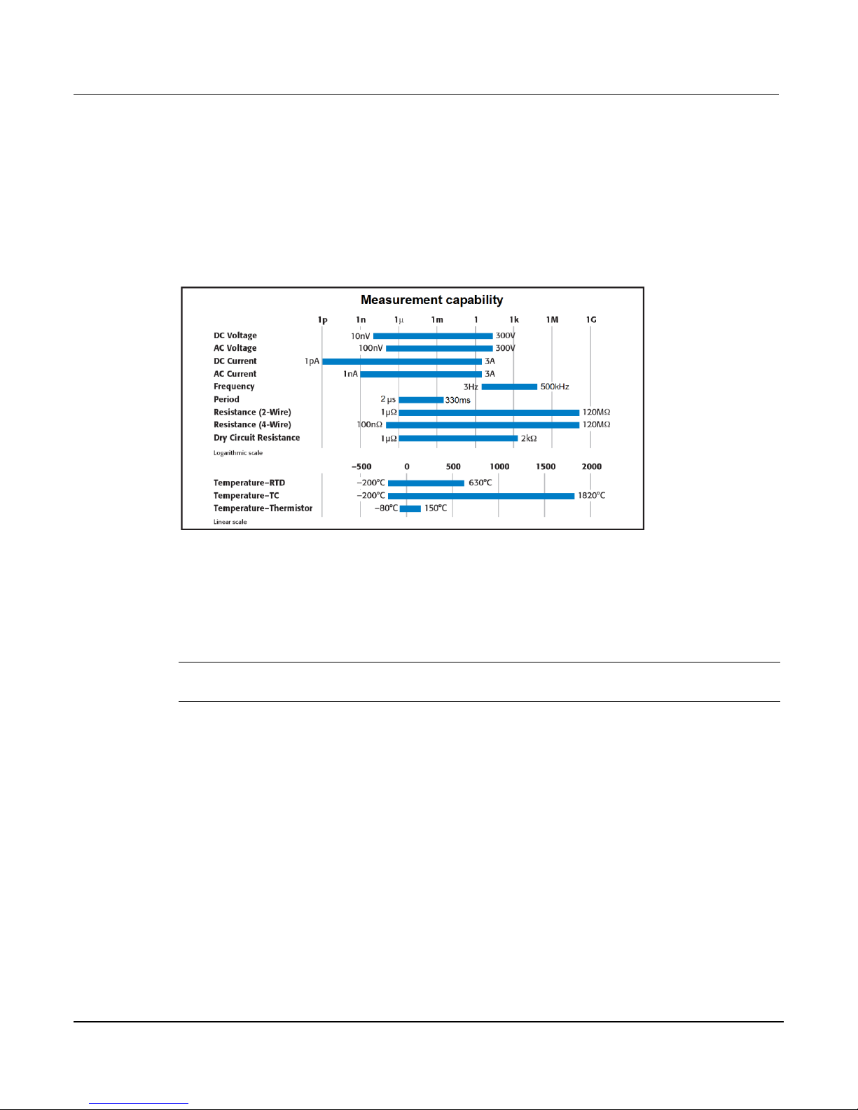
Measure and switching capabilities
The basic measurement capabilities of Series 3700 systems are summarized in the following
figure.
Figure 1-1: DMM measurement capabilities
Introduction
This Quick Start Guide is intended to get a new user familiar with the operation of the
instrument. It summarizes operation for basic measurement functions and most features of the
Series 3700 instruments as well as provides answers to frequently asked questions.
NOTE In this guide, front panel controls are described. Your specific Series 3700 model may
or may not be equipped with all front panel controls and indicators shown.
User manual content
Refer to the Series 3700 User’s Manual for Series 3700 operations including a listing of
applicable Instrument Control Library (ICL) commands. The User's Manual includes important
additional information on topics covered in the Quick Start Guide, and full details on topics not
covered in this guide.
Details on the switching modules are covered in the Section 9 of the User’s Manual.
Page 14

Series 3700 System Switch/Multimeter Quick Start Guide Section 1: Introduction
Document Number: 3700S-903-01 Rev. A / August 2007 1-3
Reference manual content
Refer to the Series 3700 Reference Manual for specific listing of advanced operation including:
Range
Digits
Rate Bandwidth
Filter
Relative
Math
dB
Buffer
Scanning
Calibration
Also included in the reference manual is a detailed listing of the Instrument Control Library (ICL)
commands.
Warranty information
Detailed warranty information is located at the front of this manual. Should your Series 3700
require warranty service, contact the Keithley Instruments representative or authorized repair
facility in your area for further information. When returning the instrument for repair, be sure to
complete the service form at the back of this manual and give it to the repair facility with all
relevant information.
NOTE The service form requires the serial number of the Series 3700. The serial number
label is located inside the unit on the bottom panel. The serial number can be viewed
by removing the slot covers and/or switching modules from the mainframe.
WARNING Before removing (or installing) switching modules, make sure you turn off
the Series 3700 and disconnect the line cord. Also, remove any other
external power connected to the instrument or switching module(s).
Failure to remove power before removing (or installing) switching
modules may result in personal injury or death due to electric shock.
Page 15
Section 1: Introduction Series 3700 System Switch/Multimeter Quick Start Guide
1-4 Document Number: 3700S-903 -01 Rev. A / August 2007
Displaying the unit's serial number
To display the serial number on the front panel:
NOTE If the Series 3700 is in remote mode, press the EXIT key once to place the unit in local
mode.
1. When in local mode, press the MENU key.
2. Scroll to the SYSTEM-INFO menu and press the ENTER key.
3. On the SYSTEM INFORMATION menu, scroll to the SERIAL# and press the ENTER key.
The Series 3700 serial number will be displayed.
Safety symbols and terms
The following symbols and terms may be found on the System Switch/Multimeter or used in this
manual:
The symbol indicates that the user should refer to the operating instructions located in the
manual.
The symbol shows that high voltage may be present on the terminal(s). Use standard safety
precautions to avoid personal contact with these voltages.
The symbol on an instrument shows that the surface may be hot. Avoid personal contact to
prevent burns.
The WARNING heading used in this manual explains dangers that might result in personal
injury or death. Always read the associated information very carefully before performing the
indicated procedure.
The CAUTION heading used in this manual explains hazards that could damage the unit. Such
damage may invalidate the warranty.
Page 16
In this section:
Front panel introduction ................................................................................... 2-1
Display ........................................................................................................... 2-3
Front panel keys ............................................................................................. 2-6
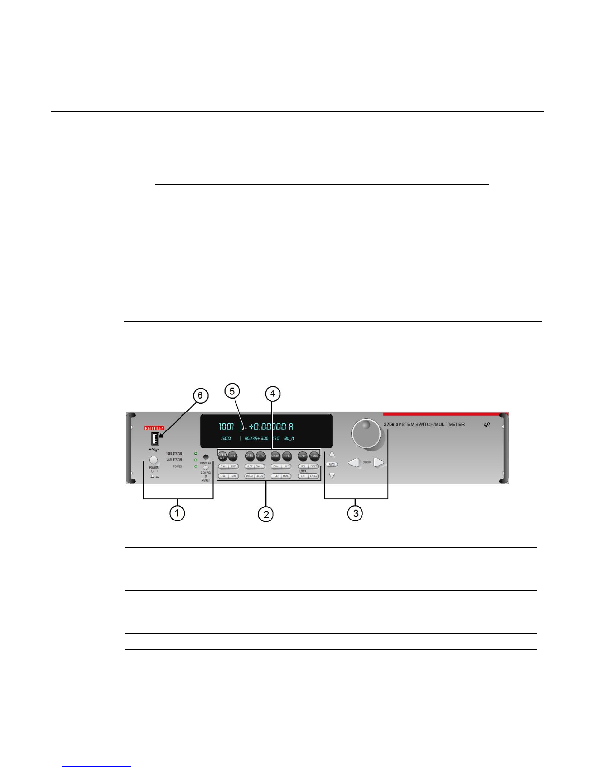
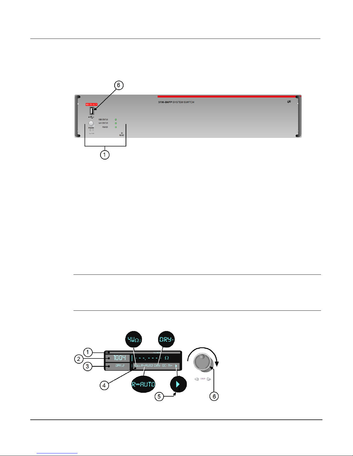
Item
Description
1
Special keys and power switch (quick start guide) (see "Special keys and power switch" on
page 2-6)
2
Operation keys (quick start guide) (see "Operation keys" on page 2-7)
3
Range, multifunction keys, and wheel (quick start guide) (see "Range, multifunction keys,
and wheel" on page 2-8)
4
Function keys (quick start guide) (see "Function keys" on page 2-8)
5
Display (on page 2-3)
6
USB connector (see "USB connectors" on page 3-4)
Section 2
Using the Front Panel
Front panel introduction
Typical Series 3700 front panels are shown below.
NOTE Not all models will have a DMM installed. All DMM related documentation is not
applicable to those models.
Figure 2-1: Model 3706 System Switch/Multimeter
Page 17
Section 2: Using the Front Panel Series 3700 System Switch/Multimeter Quick Start Guide
2-2 Document Number: 3700S-903 -01 Rev. A / August 2007
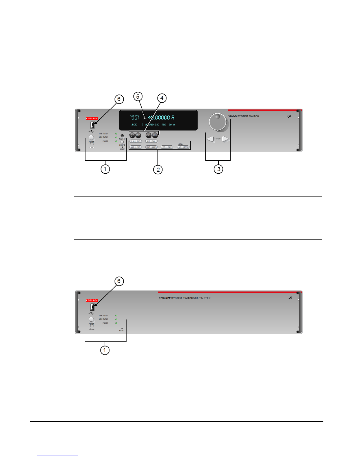
Figure 2-2: Model 3706-S System Switch (no DMM)
NOTE If your model does not have a front panel, please refer to the reference manual for
information on how to change:
1. GPIB address with gpib.address command.
2. LAN configuration using LAN functions. To see current settings for LAN, see the
applicable lan.status.* commands (for example, to see the present IP address of the
Series 3700, send the following command: lan.status.ipaddress.
Figure 2-3: Model 3706-NFP System Switch/Multimeter
Page 18
Series 3700 System Switch/Multimeter Quick Start Guide Section 2: Using the Front Panel
Document Number: 3700S-903-01 Rev. A / August 2007 2-3
Figure 2-4: Model 3706-SNFP System Switch (no DMM)
Display
The Series 3700 display provides visual information on the present active channel. The display,
with the wheel, provides a means to change the active channel or channel ranges, as well as
access to view and edit the various menus and menu items.
See the following figure for an active channel example. The display has the 4W and AUTO
range annunciators lit (1). Also, the active channel is 1004 (Slot 1 Channel 004). The present
state of the channel is open, and it has two poles (3). The present state of the attributes for this
channel (4) are: 4W function set for AUTO range, dry-circuit ohms disabled (DRY-), offset
compensation off (OC-). Other attributes, such as NPLC, are available for this specific active
channel (1004) as indicated by arrow (5) being lit. These may be viewed by turning the wheel (6)
to scroll through the attribute list.
NOTE Attribute lists, as well as menu lists, that are larger than the display, can be accessed
by turning the wheel (6). Displayed arrows (5) indicate additional attributes (or menu
items, as applicable) are available for access by turning the wheel (6) in the direction
the arrow points. If an arrow (5) is not displayed, there are no additional menu choices
in that direction.
Figure 2-5: Active channel display example
Page 19

Section 2: Using the Front Panel Series 3700 System Switch/Multimeter Quick Start Guide
2-4 Document Number: 3700S-903 -01 Rev. A / August 2007
The top line of the display (1) contains the following annunciators:
Annunciator
Description
* (asterisk)
Front panel readings are being stored in the selected reading buffer.
4W
4-wire resistance or RTD temperature reading displayed.
ARM
Unit armed and ready to use.
AUTO
Auto range enabled for the selected DMM function.
EDIT
Unit in edit mode (for front panel).
FILT
Filter enabled for the selected DMM function.
LSTN
Instrument addressed to listen over GPIB.
MATH
mX+b, percent, or reciprocal (1/X) calculation enabled for the selected DMM function.
REL
Relative enabled for selected DMM function.
REM
Instrument in bus remote mode or web control mode (all interfaces, LAN, GPIB, or
USB).
SMPL
Flashes whenever the DMM has completed a reading.
SRQ
Service request over GPIB.
TALK
Instrument addressed to talk over GPIB bus.
TRIG
External triggering selected. The TRIG annunciator will blink if taking continuous
triggered readings on front panel.
Front pnel DMM atribute
Symbol
Values
range
R=
AUTO or n, here n equals the range
nplc
N=
n, where n equals the nplc
auto delay
AD
+ for ON, 1 for ONCE, or 0 for OFF
auto zero
AZ
+ for ON or – for OFF
line sync
LS
+ for ON or – for OFF
limit
LIM
+ for a limit enabled or – for limits disabled
detector bandwidth
DBW
3, 30, or 300
threshold
THR=
n, where n indicates the threshold
aperture
A=
n, where n indicates the aperture setting
dry circuit
DRY
+ for ON or – for OFF
offset compensation
OC
+ for ON or – for OFF
thermocouple sensor K
K_T/C
N/A
thermocouple sensor T
T_T/C
N/A
The bottom line of the display (4) contains the attribute symbols. The symbols that appear are
dependent on whether the attribute exists for the selected function. If the symbol has also
contains a value, the third column in the table indicates the value definition. The following table
indicates the DMM attribute symbols that may appear on the front panel.
Page 20

Series 3700 System Switch/Multimeter Quick Start Guide Section 2: Using the Front Panel
Document Number: 3700S-903-01 Rev. A / August 2007 2-5
Front pnel DMM atribute
Symbol
Values
thermocouple sensor E
E_T/C
N/A
thermocouple sensor R
R_T/C
N/A
thermocouple sensor S
S_T/C
N/A
thermocouple sensor B
B_T/C
N/A
thermocouple sensor N
N_T/C
N/A
thermistor
THRM
N/A
three-wire RTD
3RTD
N/A
four-wire RTD
4RTD
N/A
simulated reference junction
RJ_SIM
N/A
internal reference junction
RJ_INT
N/A
external reference junction
RJ_EXT
N/A
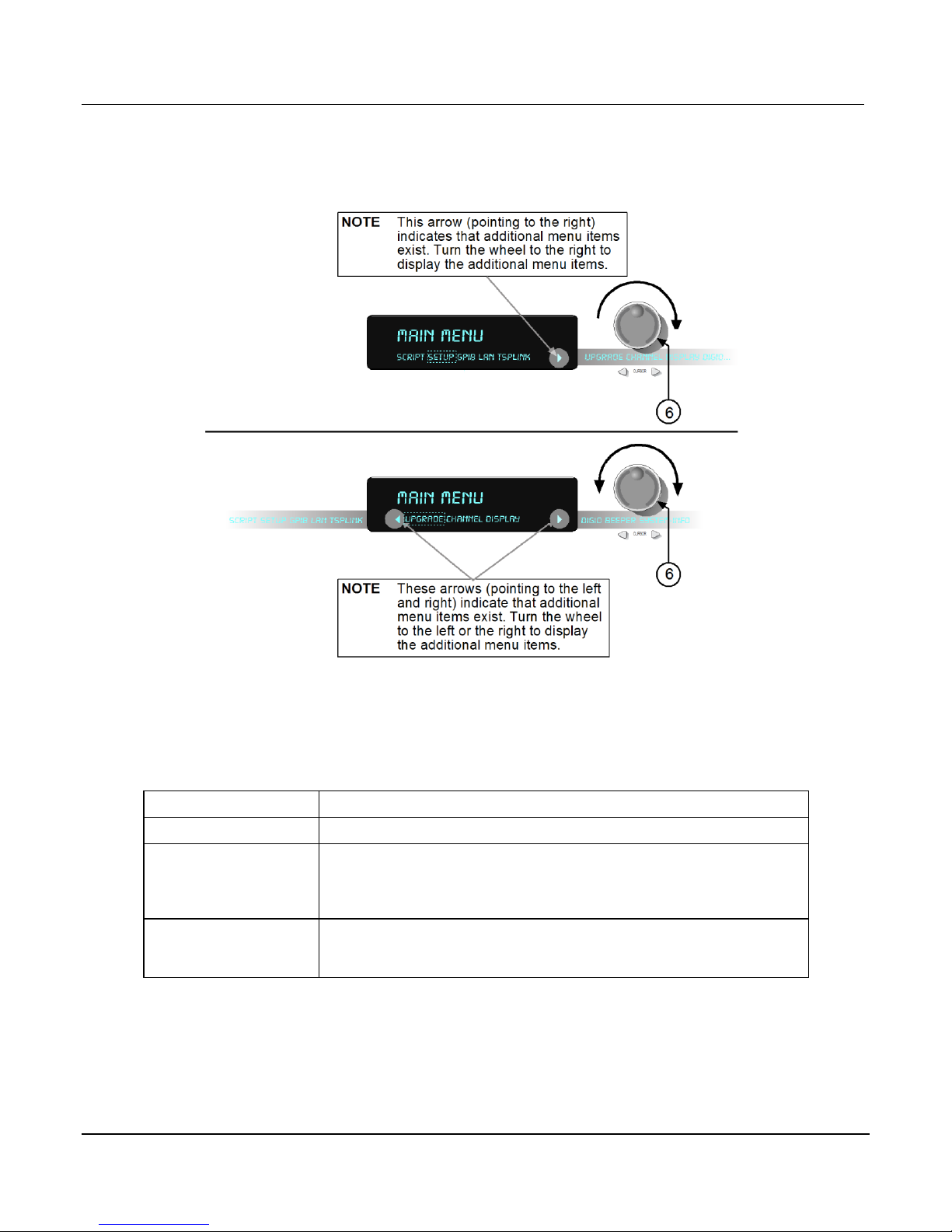
NOTE To access the main menu, press the MENU key.
See the following figure for a menu example. In the example, the MAIN MENU is displayed.
Turn the wheel (6) or press the cursor keys, to scroll through the available menu items. In the
following figure's first display, there is a right arrow indicator. This indicates there are additional
menu items to the right. In figure's second display, both right and left arrows are active indicating
there are additional items in both directions. To select the highlighted (flashing) menu item,
press the wheel (or press the ENTER key).
Page 21
Section 2: Using the Front Panel Series 3700 System Switch/Multimeter Quick Start Guide
2-6 Document Number: 3700S-903 -01 Rev. A / August 2007
Figure 2-6: MAIN MENU display
POWER switch:
Press this switch to turn the Series 3700 on (I); press it again to turn it off (O).
DISPLAY key:
Press this key to toggles between main and user display modes.
CONFIG key:
Use this key to access the an attribute menu that enables you to configure
channels, channel patterns, DMM functions, or settings, reading buffer,
scans, and other operations. Refer to the user's manual for additional
information the CONFIG key.
RESET switch:
Use this switch to restore the Series 3700 factory default LAN settings. Refer
to the reference manual LAN functions (lan.config.x, where x represents the
specific command) for factory default information.
Front panel keys
Special keys and power switch
Page 22

Series 3700 System Switch/Multimeter Quick Start Guide Section 2: Using the Front Panel
Document Number: 3700S-903-01 Rev. A / August 2007 2-7
Operation keys
CHAN key:
Pressing this key opens the CHANNEL ACTION MENU that contains the
following menu items: OPEN, CLOSE EXCLOSE, EXSLOTCLOSE, and
RESET.
PATT key:
Pressing this key opens the PATTERN ACTION MENU that contains the
following menu items: OPEN, CLOSE, EXCLOSE, EXSLOTCLOSE,
CREATE, VIEW, DELETE, and RESET.
SLOT key:
Press this key to display installed card(s) and instrument information, as well
as main system information. The information displayed includes firmware
revisions of both main and installed components. After pressing this key,
scroll through all available instruments, including the internal DMM.
SCAN key:
If a scan list is present, this key opens the SCAN ACTION MENU that
contains the following menu items: EXECUTE, CREATE, LIST, CLEAR, and
RESET.
DMM key:
Opens the DMM ACTION MENU that contains the following menu items:
MEASURE, COUNT, LOAD, SAVE, OPEN, CLOSE, RESETFUNC,
RESETALL, and CONNECT.
LIMIT key:
Pressing this key will cycle through the four combinations of limit state
settings (Limit1 and Limit2 off, Limit1 on and Limit2 off, Limit1 off and Limit2
on, Limit1 and Limit2 on).
REL key:
Pressing this key enables/disables relative for selected function. Causes REL
annunciator to light when enabled. Also see Relative in the reference manual.
FILTER key:
Pressing this key enables/disables filter for selected function. When the filter
is enabled, the FILT annunciator will light. Also see Filter in the reference
manual.
FUNC key:
Pressing this key selects the active DMM function for the channel. Related
ICL command: dmm.func
LOAD key:
Pressing this key loads user-defined scripts, along with Lua chunks added
with display.loadmenu.add for execution. This key opens the LOAD TEST
menu which contains the following menu items: USER and SCRIPTS.
RUN key:
Pressing this key runs last selected script or load menu item.
INSERT key:
Pressing this key appends the present channel to the scan list.
DELETE key:
Pressing this key deletes the present channel (including function) from the
scan list. If the present channel is not contained in the scan list, no error is
reported.
TRIG key:
Pressing this key triggers a measurement equivalent to the dmm.measure
command.
MENU key:
Pressing this key opens the MAIN MENU that contains the following menu
items: SCRIPT, SETUP, GPIB, LAN, TSPLINK, UPGRADE, CHANNEL,
DISPLAY, DIGIO, BEEPER, and SYSTEM-INFO.
EXIT key:
Cancels the selection and moves back to the measurement display.
ENTER key:
Pressing this key accepts selection, moves to next choice, or back to
measurement display.
Page 23

Section 2: Using the Front Panel Series 3700 System Switch/Multimeter Quick Start Guide
2-8 Document Number: 3700S-903 -01 Rev. A / August 2007
Range keys:
▲▼ Selects the next higher/lower measurement range for the selected
function when on measurement display.
To set the range, use the RANGE keys ▲ or ▼. If the Series 3700 displays
the overflow message on a particular range, select a higher range until an onrange reading is displayed. Use the lowest range possible without causing an
overflow to ensure best accuracy and resolution. For details see Auto ranging
over the front panel in the reference manual.
AUTO key:
Enables or disables autorange for the selected function, and causes the
AUTO annunciator to light when enabled.
CURSOR keys
◄ CURSOR ► Use the CURSOR arrows in a menu to control cursor position
for making selections or changing values.
Wheel
Turn the wheel to scroll to the desired menu option or to change the value of
the selected numeric parameter. Also, press the wheel to cause the same
function as pressing the ENTER key. Also see ENTER key. Turn the wheel to
scroll to the desired digit location to edit, press the wheel to enter edit mode,
and then turn the wheel to increase or decrease the value.
NOTE When changing a multiple character value, such as an IP address or
channel pattern name, press the wheel to enter edit mode, rotate the
wheel to change the characters value as desired, but do not leave
edit mode. Use the cursor keys to scroll to the other characters and
use the wheel to change their value as needed. Press the ENTER
key when finished changing all the characters.
OPEN ALL key:
Opens all closed channels.
STEP key:
Steps through channels associated with the defined scan list; sends a trigger
after each channel.
OPEN key:
Opens selected channels or channel pattern.
CLOSE key:
Closes specified channels or channel pattern.
STORE key:
Opens the RD BUFF ACTION MENU. This menu contains:
CREATE: Allows creation of a reading buffer, or allows you to select a
previously created reading buffer. When a new buffer is created, you can set
the number of readings to store and then select the buffer. Related
Instrument Control Library (ICL) command: dmm.makebuffer
SELECT: Allows you to select a previously created reading buffer. Related
Instrument Control Library (ICL) command: dmm.measure
CLEAR: Removes readings from a previously created buffer.
SAVE: Allows you to save a previously created reading buffer to a USB flash
drive (flash drive must be installed and have enough available space).
RECall key:
Displays stored readings and buffer statistics for selected reading buffer. Use
the ◄ CURSOR ► keys or turn the wheel to navigate through buffer.
Range, multifunction keys, and wheel
Function keys
Page 24

Series 3700 System Switch/Multimeter Quick Start Guide Section 2: Using the Front Panel
Document Number: 3700S-903-01 Rev. A / August 2007 2-9
RATE key:
Sets measurement speed (fast, medium, or slow) for the active or selected
function.
FUNCtion key:
This key select the active function by cycling through the following list as
listed. Each press of the FUNC key has the DMM and configured to the next
function in the list:
dcvolts: DC voltage
acvolts: AC voltage
dccurrent: DC current
accurrent: AC current
twowireohms: Two-wire ohm (resistance)
fourwireohms: Four-wire ohm (resistance)
commonsideohms: Common-side ohm (resistance)
frequency: Frequency
period: Period
continuity: Continuity
temperature: Temperature
Page 25

Page 26

In this section:
Rear panel summary ....................................................................................... 3-1
Rear panel connections ................................................................................... 3-2
Switching module installation and connections ................................................. 3-6
Module installation .......................................................................................... 3-7
Bus operation ................................................................................................ .. 3-11
Power-up ........................................................................................................ 3-12
Item
Description
1
Analog backplane fuse (see "Analog backplane AMPS fuse" on page 3-2)
2
Slots (6 places) (see "Slots" on page 3-2)
3
TSP-link® connectors (2 places) (see "TSP-Link connector" on page 3-2)
4
Instrument fuse (on page 3-2)
5
Power connector (on page 3-2)
6
Digital I/O port (on page 3-3)
7
GPIB connector (on page 3-4)
8
Ethernet connector (see "Ethernet connector (RJ-45)" on page 3-4)
9
USB connector (see "USB connectors" on page 3-4)
10
Analog backplane connector (on page 3-5)
Section 3
Rear Panel
Rear panel summary
Figure 3-1: Rear panel features
Page 27

Section 3: Rear Panel Series 3700 System Switch/Multimeter Quick Start Guide
3-2 Document Number: 3700S-903 -01 Rev. A / August 2007
Rear panel connections
Analog backplane AMPS fuse
FOR CONTINUED PROTECTION AGAINST FIRE HAZARD, REPLACE FUSE WITH SAME
Slots
TSP-Link connector
TYPE AND RATING (3A / 250V). See Fuse replacement for details.
Use any of the six slots of the Keithley Instruments Series 3700 for the switching modules.
When a module is not installed, make sure to cover the slot with a slot cover. For additional
information on an installed module, press the SLOT key.
Instrument fuse
Use with TSP-link cable to expand system.
FOR CONTINUED PROTECTION AGAINST FIRE HAZARD, REPLACE FUSE WITH SAME
TYPE AND RATING (1.25A / 250V). See Fuse replacement for details.
Power connector
Using the supplied line cord, connect to a grounded AC power outlet. See Line power
connection (on page 3-12) for connection details.
Page 28

Series 3700 System Switch/Multimeter Quick Start Guide Section 3: Rear Panel
Document Number: 3700S-903-01 Rev. A / August 2007 3-3
Digital I/O port
Pin
Description
1
...
9
Digital I/O #1
...
Digital I/O #9
10
...
14
Digital I/O #10 (High Current Pins see Note)
...
Digital I/O #14 (High Current Pins see Note)
15-21
Ground
22
V EXT
23
V EXT
24
NC (no connection)
25
V EXT
The Series 3700 has a digital input/output port that can be used to control external digital
circuitry. For example, a handler that is used to perform binning operations can be used with a
Digital I/O port. The Digital I/O port is a standard female DB-25 connector.
Figure 3-2: Digital I/O port
NOTE High Current Pins (10-14) can be used for binning applications or for external relays.
Page 29

Section 3: Rear Panel Series 3700 System Switch/Multimeter Quick Start Guide
3-4 Document Number: 3700S-903 -01 Rev. A / August 2007
Connecting cables
Use a cable equipped with a standard male DB-25 connector (Keithley Instruments part number
CA-126-1).
Digital I/O lines (pins 1 through 14)
The port provides 14 digital I/O lines. Each output is set high (+5V) or low (0V) and can read
high or low logic levels.
+5V output (pins 22, 23, and 25)
The Digital I/O Port provides a +5V output that is used to drive external logic circuitry. Maximum
current output for this line is 600mA. This line is protected by a self-resetting fuse (one hour
recovery time).
GPIB connector
For GPIB communication, connect to GPIB port of computer using an IEEE-488 cable (Keithley
Instruments Model 7007).
Ethernet connector (RJ-45)
For Ethernet communication, connect to Ethernet port of a computer, or to a hub or receptacle
of an Ethernet system.
To connect the Series 3700 directly to a computer, use an Ethernet cross-over cable (RJ-45,
male/male).
To connect the Series 3700 to an Ethernet system hub or receptacle, use a standard Ethernet
cable (RJ-45, male/male).
USB connectors
The downstream USB-2.0 receptacle (Type B) located on the rear panel connects to a host. The
front panel has an upstream USB-2.0 connector (Type A) that connects to a user supplied USB
flash drive.
Page 30

Series 3700 System Switch/Multimeter Quick Start Guide Section 3: Rear Panel
Document Number: 3700S-903-01 Rev. A / August 2007 3-5
Use the rear connector to communicate with the instrument over USB by sending the desired
commands. Use the front panel connector to insert a USB flash drive for saving or loading
reading buffers, user setups, or scripts. See the Reference Manual for more information on
reading buffers, user setups and scripts.
Figure 3-3: USB connectors
Analog backplane connector
Refer to the following figure for analog backplane connector information. See Connections (on
page 3-9) before making any connections.
Figure 3-4: Analog backplane connector
Page 31

Section 3: Rear Panel Series 3700 System Switch/Multimeter Quick Start Guide
3-6 Document Number: 3700S-903 -01 Rev. A / August 2007
The table below contains pin numbers and descriptions for the analog backplane connector.
Description
Pin Description
Pin
Analog backplane 3-HI
5 DMM-SLO
4
Analog backplane 3-LO
6 DMM-SHI
3
Analog backplane 4-HI
7 DMM-LO
2, 9
Analog backplane 4-LO
8 DMM-HI
1
Analog backplane 5-HI
12 AMP-LO
2, 9
Analog backplane 5-LO
13 AMP
10, 11
Analog backplane 6-HI
14
Analog backplane 6-LO
15
Switching module installation and connections
In order to exercise close/open operations explained in this section, a switching module (or
pseudocard) must be installed in the mainframe. A switching module can be installed by the
user, however external connections to the switching module are only to be performed by
qualified service personnel.
WARNING To prevent electric shock that could result in injury or death, NEVER
handle a switching module that has power applied to it:
• Before installing (or removing) a switching module, make sure the Series
3700 is turned off and disconnected from line power.
• If the switching module is already connected to a device under test
(DUT), make sure power is removed from all external circuitry.
NOTE For inexperienced users, it is recommended that DUT and external circuitry not be
connected to switching modules. This will allow you to exercise safe close/open
operations without the dangers associated with live test circuits.
Page 32

Series 3700 System Switch/Multimeter Quick Start Guide Section 3: Rear Panel
Document Number: 3700S-903-01 Rev. A / August 2007 3-7
Module installation
WARNING Slot covers must be installed on unused slots to prevent personal contact
Perform the following steps to install a switching module into the Series 3700 mainframe:
1. Turn the Series 3700 off and disconnect the power line cord and any other cables
connected to the rear panel.
2. Position the Series 3700 so that you are facing the rear panel.
3. Remove the slot cover plate from the desired mainframe slot. Retain the plate and screws
for future use.
4. With the top cover of the switching module facing up, align the module's card edge into the
slot's card guide and slide in the module. For the last ¼ inch or so, press in firmly to mate
the module connector to the mainframe connector.
5. On each side of the module, there is a mounting screw. Tighten these two screws to secure
the module to the mainframe. Do not overtighten.
6. Reconnect the power line cable and any other cables to the rear panel.
with high voltage circuits.
Page 33

Section 3: Rear Panel Series 3700 System Switch/Multimeter Quick Start Guide
3-8 Document Number: 3700S-903 -01 Rev. A / August 2007
7. Press the SLOT key to see the model numbers, description, and the firmware revision of the
Item
Description
1
Card guide (part of Series 3700)
2
Module
3
Card edge (part of module)
4
Mounting screw (part of module)
installed switching module(s), along with the mainframe firmware and DMM (if present).
Figure 3-5: Typical module installation
Page 34

Series 3700 System Switch/Multimeter Quick Start Guide Section 3: Rear Panel
Document Number: 3700S-903-01 Rev. A / August 2007 3-9
Connections
WARNING Connection information for switching modules is intended for qualified
To prevent electric shock that could result in serious injury or death,
Before making or breaking any connections to the switching module,
Do not connect signals that will exceed the maximum specifications of
If both the rear analog backplane connector of the Series 3700 and the
service personnel. Do not attempt to connect DUT or external circuitry to a
switching module unless qualified to do so.
comply with these safety precautions:
make sure the Series 3700 is turned off and power is removed from all
external circuitry.
any installed switching module.
switching module terminals are connected at the same time, the test lead
insulation must be rated to the highest voltage that is connected. For
example, if 300V is connected to the analog backplane connector, the test
lead insulation for the switching module must also be rated for 300V.
Dangerous arcs of an explosive nature in a high energy circuit can cause
severe personal injury or death. If the multimeter is connected to a high
energy circuit when set to a current range, low resistance range, or any
other low impedance range, the circuit is virtually shorted.
Dangerous arcing can result (even when the multimeter is set to a voltage
range) if the minimum voltage spacing is reduced in the external
connections. For details about how to safely make high energy
measurements, see High-energy circuit safety precautions.
As described in the International Electrotechnical Commission (IEC)
Standard IEC 664, the Series 3700 is Installation Category I and must not
be connected to mains.
Page 35

Section 3: Rear Panel Series 3700 System Switch/Multimeter Quick Start Guide
3-10 Document Number: 3700S-903 -01 Rev. A / August 2007
Pseudocards
You can perform open/close/scan operations and configure your system without having an
actual switching module installed in your Series 3700. Using remote programming, you can
assign a pseudocard to an empty switching module slot, allowing the Model 3700S to operate as
if a switching module were installed.
A pseudocard, which is essentially a "virtual switching module," cannot be installed from the
front panel. However, once the remote installation is complete, you can take the Series 3700 out
of remote mode and use the front panel. Pressing the LOCAL or EXIT key takes the Series
3700 out of remote mode.
When the instrument is turned off, the pseudocard will be lost (uninstalled). In order to recall a
pseudocard, make it part of a saved setup.
NOTE A saved setup retains the model number of the module installed in each slot. The
model number of a pseudocard is the same as the model number of an actual module.
This allows a saved setup to be recalled provided the installed card (or pseudocard)
matches the model number for the slot in the saved setup.
Pseudocards programming example
Use the following command line to set the pseudocard of Slot 6 for 3720 Dual 1 x 30 Multiplexer
card simulation:
Channel assignments
Each switching module has a certain number of channels. For example, the Model 3720
switching module has 60 channels (1 through 60). When you encounter a 1 to 3-digit channel
number in this manual, the switching module channel is the point of discussion. A four-digit
channel number includes the slot followed by the 3-digit channel number.
A switching module can be installed in any of the mainframe's six slots. Therefore, to close,
open, or scan a channel, it is necessary to specify the slot location and channel number of the
switching module. This is accomplished by using a four-digit channel number for the mainframe.
The first digit (1, 2, 3, 4, 5, or 6) indicates the slot number, and the next three digits indicate one
of the following:
The channel number of a switching module (see "Mux (multiplexer) channel notation" on
page 4-5)
The row and column of a matrix card (see "Matrix card notation" on page 4-5)
slot[6].pseudocard = slot.PSEUDO_3720
The modules' backplane relay (see "Backplane relay notation" on page 4-4)
Page 36

Series 3700 System Switch/Multimeter Quick Start Guide Section 3: Rear Panel
Document Number: 3700S-903-01 Rev. A / August 2007 3-11
Bus operation
The Series 3700 supports bus operation over USB, Ethernet and GPIB. The GPIB settings may
be set from the front panel, or once controlled by the bus, over the bus.
1. Viewing or configuration using the front panel:
2. Viewing or configuration over the bus:
USB is always connected and available to send bus commands. There are no unique USB
settings. To use USB, make sure have installed the Test Script Builder application. The
applicable USB driver is available after installing this software.
NOTE For your Series 3700 to be recognized by your computer over the USB interface, the
a) Press MENU key to bring up the main menu,
b) Turn the wheel to scroll to "GPIB" menu item and press the ENTER key.
c) Select setting to change ADDRESS or ENABLE
a) gpib.address to change the address
b) gpib.enable to change the enable setting.
ON: GPIB will respond to bus commands.
OFF: GPIB will not respond to bus commands.
proper driver must be installed. Installing the Test Script Builder application also
installs the applicable USB driver (it becomes available after installing this software).
To complete the USB driver installation, after installing the Test Script Builder
application, connect the Series 3700 USB connector (rear panel) to the computer.
Ethernet supports various settings. The LAN logical device has options that show the current
status under lan.status commands while it has pending configuration settings under lan.config.
The config settings will take effect when lan.applysettings is executed. Using the lan.reset
command is equivalent to doing a lan.restoredefaults followed by a lan.applysettings. To only
restore defaults without resetting to them, use the lan.restoredefaults command by itself. Please
refer to the LAN ICLs directly for individual settings that may be controlled with the LAN logical
device. From the front panel, the LAN (Ethernet) options may be enabled or disabled collectively
under MAIN MENU and LAN settings. From the bus, one may enable or disable certain aspects
of LAN with:
1. comm.lan.telnet.enable
2. comm.lan.web.enable
3. comm.lan.vxi11.enable
4. comm.lan.rawsockets.enable
Page 37

Section 3: Rear Panel Series 3700 System Switch/Multimeter Quick Start Guide
3-12 Document Number: 3700S-903 -01 Rev. A / August 2007
The following list contains the four LAN default port numbers (along with corresponding ICLs to
query for these values):
1. telnet is 23 (ICL: lan.status.port.telnet)
2. rawsocket is 5025 (ICL: lan.status.port.rawsocket)
3. vxi11 is 1024 (ICL: lan.status.port.vxi11)
4. dead socket termination is 5030 (ICL: lan.status.port.dst)
When changing between the various bus interfaces, send the abort command to have that
interface become the active one for receiving and processing bus commands. For example, if
changing from communicating with instrument over GPIB and to send ICLs with a telnet session
(assuming both interfaces are enabled):
1. Connect via telnet.
2. Send abort to leave the GPIB interface and switch over to telnet.
3. Send commands as desired.
Any of the enable settings will take effect the next time the unit powers up. Therefore, after
making changes to these settings, power cycle the unit.
Power-up
Line power connection
Follow the procedure below to connect the Series 3700 to line power and turn on the instrument.
The Series 3700 operates from a line voltage of 100V to 240V at a frequency of 50Hz or 60Hz.
Line voltage is automatically sensed. There are no switches to set. Make sure the operating
voltage in your area is compatible.
WARNING The power cord supplied with the Series 3700 contains a separate ground
wire for use with grounded outlets. When proper connections are made,
instrument chassis is connected to power line ground through the ground
wire in the power cord. Failure to use a grounded outlet may result in
personal injury or death due to electric shock.
CAUTION Operating the instrument on an incorrect line voltage may cause damage to the
instrument, possibly voiding the warranty.
Page 38

Series 3700 System Switch/Multimeter Quick Start Guide Section 3: Rear Panel
Document Number: 3700S-903-01 Rev. A / August 2007 3-13
1. Before plugging in the power cord, make sure that the front panel power switch is in the off
(O) position. See Rear panel summary (on page 3-1) for connector location.
2. Connect the female end of the supplied power cord to the (5) Power Connector (AC
receptacle) on the rear panel. Connect the other end of the power cord to a grounded AC
outlet.
3. Turn on the instrument by pressing the front panel power switch to the on (I) position. See
Front panel introduction for switch location.
Line frequency
NOTE Line frequency only applies to models with a DMM installed.
The Series 3700 will operate at line frequencies of either 50Hz or 60Hz. The line frequency is
auto-detected at startup.
Use the localnode.linefreq bus command to see the line frequency. For example:
Fuse replacement
print(localnode.linefreq)
Refer to the Fuse replacement topic contained in the user's manual for fuse replacement
information.
Power-up sequence
On power-up, the Series 3700 performs self-tests on its ROM, NVRAM, and RAM and
momentarily lights all segments and annunciators. If a failure is detected, the instrument
momentarily displays an error message and the ERR annunciator turns on. (Error messages are
listed in Error and status messages contained in the Reference manual.)
NOTE If a problem develops while the instrument is under warranty, return it to Keithley
Instruments, Inc., for repair.
Assuming no errors occur, the Series 3700 will power-up as follows:
1. "No Comm Link" is briefly displayed.
2. "Initializing" is displayed for several seconds.
3. Nearing the end of initialization, the 1588 and LAN status LEDs light.
4. All of the display pixels briefly light.
Page 39

Section 3: Rear Panel Series 3700 System Switch/Multimeter Quick Start Guide
3-14 Document Number: 3700S-903 -01 Rev. A / August 2007
5. The display shows:
KEITHLEY
Series 3700
System identification
6. Main display appears.
Serial number, firmware revision, and calibration dates can be displayed by selecting the
SYSTEM-INFO item of the main menu (press MENU > SYSTEM-INFO).
Select FIRMWARE, SERIAL#, or CAL as desired.
For remote programming, use the *IDN? query to read system information.
Beeper
With the beeper enabled, a beep will be issued to acknowledge the following actions:
A short beep, emulating a keyclick, is issued when a front panel key is pressed.
A short beep, emulating a keyclick is also issued when the wheel is turned or pressed.
To control the beeper from the front panel, select MENU > BEEPER > KEYCLICK, then
ENABLE or DISABLE the keyclick as desired.
For remote programming, use the beeper.enable command to control the beeper. For
example, the following enables the beeper:
beeper.enable = 1
Page 40

In this section:
General questions ................................................................ ........................... 4-1
Questions about web page operation ............................................................... 4-12
Questions about remote operation ................................................................... 4-15
Questions about Test Script Processor interaction ............................................ 4-24
Section 4
Frequently Asked Questions
General questions
How do I power up the instrument?
Step 1: Connect to line power
CAUTION Operating the instrument on an incorrect line voltage may cause damage to the
1. Before plugging in the power cord, make sure that the front panel power switch is in the off
(O) position.
2. Connect the female end of the supplied power cord to the AC receptacle on the rear panel.
Connect the other end of the power cord to a grounded AC outlet.
WARNING Failure to use a grounded outlet may result in personal injury or death due
instrument, possibly voiding the warranty.
to electric shock.
Step 2: Turn on power
Turn on the instrument by pressing the front panel power switch to the on (I) position. Assuming
no errors occur, the Series 3700 will power-up as follows:
The unit will initialize
KEITHLEY
SERIES 3700 will be displayed.
NOTE The line frequency is automatically sensed at power-up.
Page 41

Section 4: Frequently Asked Questions Series 3700 System Switch/Multimeter Quick Start Guide
4-2 Document Number: 3700S-903 -01 Rev. A / August 2007
How do I control switches?
NOTE This paragraph provides information for controlling switches using channel operation
(for channel pattern operation, refer to the Channel pattern operation paragraph
contained in the User's manual). It contains information on opening and closing all
switches from the front panel, as well as over the bus.
Close/open overview
NOTE This section provides basic close/open information for switching module channels.
Operating characteristics unique to a specific Series 3700 switching module are
provided in an instruction sheet provided with the specific switching module.
Terminology used throughout this manual is detailed in the applicable sections of the
user's and reference manuals.
The switching channels of a Series 3700 support a concept of "duality." This means that each
channel has specific settings for switching and specific settings for switching with DMM
operations. The location of the specific operation request determines the setting that activates.
An operation request residing in the channel logical device causes the switching settings to be
used (example commands are channel.close, channel.open, channel.exclusiveclose); an
operation request residing in the DMM logical device such as dmm.close or dmm.open, causes
the DMM settings to be used. Refer to the reference manual for more information on logical
devices (TSP section).
Open a Microsoft web-browser and type in the IP address (see How do I connect to the internal
web page? (on page 4-12) located in the Quick Start Guide). The Series 3700 home page will
appear. Use this home page to see a visual representation of the present channel status (select
the desired slot or model contained under "Cards").
NOTE Java application may need to be installed.
The Series 3700 supports opening and closing channels through either Channel operation or
through Channel pattern operation:
Channel operation (non-channel pattern operation): This mode of operation should be used
exclusively by most (if not all) users. When you close a channel for a measurement operation,
other channels on the switching module close automatically to internally connect it through the
backplane to the DMM of the Series 3700. When you close a channel for a switching operation,
the channel (and possibly the channel pair) will close but, no backplane relays are closed unless
associated with the channel.
Channel pattern operation: This mode of operation provides additional flexibility by providing
individual control of each switching module and backplane channel. Careless operation in this
mode could create a safety hazard and/or damage the switching module and other equipment.
Channel pattern operation should only be used by experienced test engineers.
Page 42

Series 3700 System Switch/Multimeter Quick Start Guide Section 4: Frequently Asked Questions
Document Number: 3700S-903-01 Rev. A / August 2007 4-3
WARNING Careless channel pattern operation could create an electric shock hazard
ICL
Description
Usage
channel.close
Function: Closes specified
items in ch_list without
opening any channels.
channel.close(ch_list)
ch_list: string listing the items to close.
Items can include channels, backplane
relays, and channel patterns.
channel.open
Function: Opens items
specified in ch_list.
channel.open(ch_list)
ch_list: string listing the items to open.
Items can include channels, backplane
relays, and channel patterns.
dmm.close
Function: Closes the
specified channel or channel
pattern in preparation for a
DMM measurement.
dmm.close(ch_list)
ch_list: string listing the channel or channel
pattern to close
dmm.open
Function: Opens the
specified channel and/or
channel pattern.
dmm.open(ch_list)
ch_list: string listing the channel or channel
pattern to open
that could result in severe injury or death. Improper operation can also
cause damage to the switching modules and external circuitry. Controlling
multiple channels using channel patterns should be restricted to
experienced test engineers who recognize the dangers associated with
multiple channel closures.
CAUTION To prevent damage to a switching module, do not exceed the maximum signal
level input for that module. Most switching modules are rated for 300V.
NOTE The Series 3700 is capable of scanning switching module channels. Each channel in
the scan can have its own unique DMM configuration.
Close/open bus operation
Use the following commands to control switches over the bus. For detailed information
specifying what happens with each of these commands, see the reference manual.
Page 43

Section 4: Frequently Asked Questions Series 3700 System Switch/Multimeter Quick Start Guide
4-4 Document Number: 3700S-903 -01 Rev. A / August 2007
Close/open key operation
Reference
Analog backplane relay
1921
analog backplane relay 1
1922
analog backplane relay 2
1923
analog backplane relay 3
1924
analog backplane relay 4
1925
analog backplane relay 5
1926
analog backplane relay 6
The front panel CLOSE and OPEN keys operate in the same manner as one of the following:
channel.close and channel.open commands
dmm.close and dmm.open commands
The operation of the keys depend on the selected channel or channel patterns function
association.
To have the keys work as channel.close and channel.open:
Make sure the DMM function of the DMM configuration associated with the selected
channel or channel pattern is "nofunction."
To have the keys work as dmm.close and dmm.open:
Make sure the DMM function of the DMM configuration associated with the selected
channel or channel pattern is not "nofunction" (for example, DC volts).
Channel and backplane notation
There are three different notations used to control relays: Backplane relay notation, Mux
(multiplexer) channel notation, and Matrix card notation.
Backplane relay notation
To control analog backplane relays for slots with analog backplane relay channels, use S9BX
where:
S: Slot number
9: Backplane notation designation (always 9 when referencing a backplane relay)
B: Bank number
X: Analog backplane relay number
Analog backplane relays (bank 2 of Slot 1) examples:
Page 44

Series 3700 System Switch/Multimeter Quick Start Guide Section 4: Frequently Asked Questions
Document Number: 3700S-903-01 Rev. A / August 2007 4-5
Mux (multiplexer) channel notation
Reference
Slot
Channel
1004
1
004
1020
1
020
2100
2
100
3003
3
003
Reference
Slot
Row
Column
1104
1 1 04
1203
1 2 03
2305
2 3 05
To control channels using mux channel notation, use SCCC where:
S: Slot number
CCC: Channel number (always use 3 digits)
Multiplexer examples:
Figure 4-1: Multiplexer card display
Matrix card notation
To control channels using matrix card notation, use SRCC where:
S: Slot number
R: Row number
CC: Column number (always use 2 digits)
Matrix channel examples:
Page 45

Section 4: Frequently Asked Questions Series 3700 System Switch/Multimeter Quick Start Guide
4-6 Document Number: 3700S-903 -01 Rev. A / August 2007
Reference
Slot
Row
Column
3112
3 1 12
6101
6 1 01
Figure 4-2: Matrix card display
Channel list parameter <ch_list>
The channel list parameter <ch_list>, used when controlling the Series 3700's relays over the
bus, is a string-type parameter. An example:
Channel 1 (of Slot 1) is associated with analog backplane relays 3 and 4, while Channel
3 (of the same slot) has analog backplane relays 5 and 6. The <ch_list> used in this
example is ("1001, 1003"). The response to a channel.getbackplane("1001, 1003") will
be "1913, 1914;1915,1916". To associate the backplane relays as indicated with
Channel 1, the corresponding command would be channel.setbackplane('1001', '1913,
1914').
Therefore, when sending this parameter:
Enclose the contents of the channel list in either single (') or double (") quotes, but the
quote style must match.
Use a comma or semicolon to separate the channel list or channel patterns.
The string may contain a single channel, channel pattern or analog backplane relay as
well as multiple ones that are indicated by a range or comma separated.
Use a colon to specify a range of channels. Example:
channel.getbackplane("1001:1003") responds with the range of Slot 1 channels from 1 to
3.
Although a parameter string may be valid, the command that calls it will determine the string's
ultimate validity. For example, only channels have a pole setting (channel patterns do not). If a
channel pattern is passed to the poles setting command, an error would be generated.
Channel patterns may be included as a <ch_list> parameter.
Page 46

Series 3700 System Switch/Multimeter Quick Start Guide Section 4: Frequently Asked Questions
Document Number: 3700S-903-01 Rev. A / August 2007 4-7
<ch_list> queries
For queries that return a channel list parameter, a channel configured for 4-pole operations will
indicate the paired channel in parenthesis. For example, Channel 3003 on a 60-channel card is
configured for 4-pole, then sending:
channel.close('3003')
print(channel.getclose('slot3') 3003(3033)
NOTE In the above examples output the paired channel associated with 3003 is 3033 and
is in included in parenthesis.
How do I make measurements?
Step 1: Connect the DUT
Connect a 10k resistor to the input terminals as shown.
Figure 4-3: Two-wire resistance measurements
Step 2: Select measurement function and range
Page 47

Section 4: Frequently Asked Questions Series 3700 System Switch/Multimeter Quick Start Guide
4-8 Document Number: 3700S-903 -01 Rev. A / August 2007
Select the 2-wire resistance measurement function by pressing the FUNC key until
twowireohms is displayed.
Select the measurement range with the RANGE keys. For the purposes of this example,
press AUTO RANGE, and note the AUTO annunciator turns on. The instrument will
automatically select the best range based on the measured value. You can also use
manual ranging by pressing the up or down RANGE key, but be sure to use the lowest
possible range for best accuracy.
Step 3: Make measurements
Observe the readings on the display. (Press the TRIG key if necessary to trigger the unit
to begin taking readings.)
Single channel through switch
Step 1: Connect the DUT
Connections for the switching module are shown below. As shown, each of the 20 channels can
be used to perform 2 measurements.
Figure 4-4: Two-wire switching module resistance connection
Step 2: Select measurement function and range
Select the 2-wire resistance measurement function by pressing the FUNC key until
twowireohms is displayed.
Select the measurement range with the RANGE keys. For the purposes of this example,
press the AUTO RANGE key, and note the AUTO annunciator turns on. The instrument
will automatically select the best range based on the measured value. You can also use
manual ranging by pressing the up or down RANGE key, but be sure to use the lowest
possible range for best accuracy.
Step 3: Make measurements
Observe the readings on the display. (Press TRIG if necessary to trigger the unit to begin
taking readings.) Press the TRIG key once to take a single reading. Hold the TRIG key
down to put the front panel in continuous trigger operation. Once in continuous trigger
operation press any key to stop continuous trigger of readings.
Page 48

Series 3700 System Switch/Multimeter Quick Start Guide Section 4: Frequently Asked Questions
Document Number: 3700S-903-01 Rev. A / August 2007 4-9
How do I create a scan (with reading buffer)?
NOTE A reading buffer has to be created and selected before it can be used to store data.
To create a scan that sends it's measured readings to a reading buffer:
1. If a reading buffer that you wish to use has not already been created, create a reading
buffer:
Pressing the STORE key. The RD BUF ACTION MENU will be displayed.
Highlight CREATE and press the ENTER key.
Edit the reading buffer name as desired. Press the wheel (or the ENTER key) to enter edit
mode (the EDIT annunciator will light). Turn the wheel to change the characters values, use
the CURSOR keys to change the character being edited. Press the ENTER key to leave the
edit mode.
Enter the CAPACITY you would like the buffer to have in number of readings. Press the
ENTER key to save the capacity.
2. Select the desired reading buffer:
Pressing the STORE key. The RD BUF ACTION MENU will be displayed. Highlight SELECT
and press the ENTER key. Highlight the desired buffer and press the ENTER key.
3. Add channels and DMM configurations.
Use the wheel to configure a channel that you would like added to the scan. Change to any of
the available channels and setup that channel with the associated DMM configuration that is
desired for the measurement.
The first press of the wheel (or ENTER key) will select the slot (from 1-6).
The second press of the wheel (or ENTER key) will select the channel number (card
dependent).
The third press of the wheel (or ENTER key) will select a range (card dependent).
The fourth press of the wheel (or ENTER key) will select the function (card dependent).
4. Press the INSERT key to add the step to the scan. Steps are added in the same order that
they have been entered from the front panel.
5. Continue adding steps as desired by repeating steps 3 and 4.
6. When finished adding steps to the scan, press the SCAN key. Select EXECUTE or
EXECUTE BACKGROUND to run the scan. Press the TRIG key to trigger measurements.
When finished, press the REC key and turn the wheel to view the contents of the reading
buffer.
Page 49

Section 4: Frequently Asked Questions Series 3700 System Switch/Multimeter Quick Start Guide
4-10 Document Number: 3700S-903 -01 Rev. A / August 2007
How do I save data to a USB flash drive?
setup.save
Function: Saves the
present setup as a
user-setup.
To save to the internal memory location, send no
parameters with function:
setup.save()
To save to the USB flash drive:
setup.save(location)
location: Setup location to save. Use the format
"usb1/<filename>" where <filename> is the name
of the desired file contained on a USB flash drive.
NOTE A reading buffer has to be created, selected, and must contain data before it can be
saved to a USB flash drive.
To save a reading data buffer to an attached USB flash:
1. Select the desired reading buffer by pressing the STORE key. The RD BUF ACTION MENU
will be displayed. the SELECT menu item is not displayed, you need to create a reading
buffer (and place readings in that buffer) before continuing.
2. Turn the wheel to highlight the SAVE menu item.
3. Press the wheel (or the ENTER key). SAVE RD BUFFER will be displayed.
4. Press the wheel (or the ENTER key) to select USB.
5. Edit the file name as desired.
Press the wheel (or the ENTER key) to enter edit mode (the EDIT annunciator will light).
Turn the wheel to change the characters values, use the CURSOR keys to change the
character being edited.
6. Press the ENTER key to exit edit mode and again to save the buffer to the USB drive. If an
error is displayed, check that your reading buffer has readings present. The created file is
located in on the root directory of your USB flash drive. the drive may be removed from the
Series 3700 after data transfer has completed.
How can I save/recall setups from the internal memory or USB drive?
Save a setup (bus operation)
Setups are saved over the bus to either internal memory or to a connected USB flash drive. To
save a setup, use the following command:
For example: Send the following to save a user setup to a file named KEITHLEY_3730 on a
USB flash drive:
setup.save("/usb1/KEITHLEY_3730")
Page 50

Series 3700 System Switch/Multimeter Quick Start Guide Section 4: Frequently Asked Questions
Document Number: 3700S-903-01 Rev. A / August 2007 4-11
setup.recall
Function: Recalls
settings from a saved
setup.
setup.recall(location)
location: Setup number to recall (0, 1, or
"/usb1/<filename>").
0: Reset setup.
1: Internal setup.
<filename>: Use the name of the desired file
contained on a USB flash drive.
Recall a setup (bus operation)
Setups are recalled over the bus from either internal memory or from a connected USB flash
drive. Recalling a setup also may be used to reset to the factory default setup. To recall a setup
over the bus, use the following command:
For example: Send the following to recall a user saved setup stored in a file named
KEITHLEY_3730 on an installed USB flash drive:
Save/recall/reset setup (front panel)
Using the front panel, you can save the present setup to internal memory (overwriting the
existing setup), reset to the factory default settings, or recall an existing setup from internal
memory.
To save or recall a setup from the front panel:
NOTE Press the EXIT key to place in local mode if the Series 3700 is in remote mode (being
controlled over the bus),
1. Press the MENU key (1).
2. Use the wheel (2) to select the "SETUP" menu item and press the ENTER key.
3. Use the wheel (2) to select menu item as desired:
SAVE: Press the ENTER key to have the present setup overwrite the existing internal memory
setup.
RECALL: Press the ENTER key to have the internal saved setup recalled overwriting the
present setup.
RESET: Press the ENTER key to have the factory default setup overwrite the present setup.
setup.recall("/usb1/KEITHLEY_3730")
NOTE Setups saved on the USB flash drive cannot be recalled from the front panel (use the bus
to recall USB setups).
Page 51

Section 4: Frequently Asked Questions Series 3700 System Switch/Multimeter Quick Start Guide
4-12 Document Number: 3700S-903 -01 Rev. A / August 2007
Figure 4-5: Setup menu
Questions about web page operation
How do I connect to the internal web page?
To connect to the Series 3700 web page, open the Series 3700 IP address with a web browser.
The IP address can be found by performing the following procedure:
1. Press the MENU key.
2. Select LAN and press the ENTER key.
3. Select STATUS and press the ENTER key.
4. Select IP_ADDRESS and press the ENTER key. If you would like to modify the LAN
parameters, see How do I change the Series 3700 LAN parameters? (on page 4-13).
The present IP address of the Series 3700 will be displayed. To use this IP address, enter the IP
as a web address. For example, to open the IP address of 192.168.1.101
1. Enter http://192.168.1.101 in the address box of a supported web browser
2. Press the enter key on your computer's keyboard.
Figure 4-6: Network address example
Page 52

Series 3700 System Switch/Multimeter Quick Start Guide Section 4: Frequently Asked Questions
Document Number: 3700S-903-01 Rev. A / August 2007 4-13
How do I change the Series 3700 LAN parameters?
To change the Series 3700 LAN parameters:
1. Press the MENU key.
2. Select LAN and press the ENTER key.
3. Select CONFIG and press the ENTER key.
4. Enter and modify the parameters as needed.
5. When finished with all entries, press the EXIT key to move up one level in the menu.
6. Select APPLY press the ENTER key for the new LAN settings to take affect. The updated
information will be available in the STATUS menu item of the LAN MENU.
What am I able to do through the web page?
The Series 3700 has a Web interface that complies with LXI class B requirements and offers a
convenient way to communicate with the Series 3700 from a PC browser. For more information
on LXI compliance, see http://www.lxistandard.org/home. The Series 3700 web pages (including
LXI class B compliant web pages) include the following features:
Home page
DMM control
Switch cards
Scan builder
TSB embedded
Log
Admin: Administration (includes password control)
LXI page (IP configuration, Sync configuration)
Schedule
Help
Page 53

Section 4: Frequently Asked Questions Series 3700 System Switch/Multimeter Quick Start Guide
4-14 Document Number: 3700S-903 -01 Rev. A / August 2007
NOTE For proper operation of the Web interface after each firmware update, you must
1. In the browser window, click Tools > Internet Options.
2. In the General tab, click Settings.
3. In the Check for newer version of stored pages: section, select Every visit to the
4. Click OK.
The Web interface also offers the following features:
Save readings, TSP scripts locally to PC
Multiple "view only" access to the instrument
Print screen capability from Web browser
The LXI Welcome page is shown below:
Figure 4-7: Home page
change the browser refresh policy. The following procedure is for Internet Explorer (for
other browsers, use the procedure as a guideline):
page.
Home page
This page describes the instrument model and manufacturer, serial number, switch cards, last
LXI message, raw socket port and TELNET port.
Page 54

Series 3700 System Switch/Multimeter Quick Start Guide Section 4: Frequently Asked Questions
Document Number: 3700S-903-01 Rev. A / August 2007 4-15
LXI Web interface setup
To access the instrument and control the operation over the LXI Web interface, you must install
a Sun Java Runtime Environment (JRE)(version 1.6 or above) as a web browser plug-in in the
computer that is connected to the instrument. The Series 3700 Product Information CD-ROM
that accompanied your Keithley Instruments Series 3700 contains a Java Runtime Environment
Update. This JRE contains the Java virtual machine, runtime class libraries, and Java
applications browser plug-in necessary to run the program that accesses and controls the
instrument through the LXI Web interface.
You may download the appropriate JRE from the Sun Microsystems Website:
1. Using your internet browser, type in the following URL:
http://java.sun.com/javase/downloads/index.jsp
2. Find the latest available Java Runtime Environment (JRE) update and download.
Questions about remote operation
What remote interfaces can I use?
You can automate commonly recurring test procedures by sending remote control commands to
the instrument over GPIB, Ethernet (LAN), or USB. You can also access the instrument and
control the operation using the LXI Web interface.
Step 1: Connect to the interface
To learn about the configuration requirements and programming commands, see the following
topics:
GPIB interface (see "GPIB interface connection" on page 4-16)
Standard RJ-45 (Ethernet) interface (see "Standard RJ-45 (Ethernet) interface connection" on
page 4-16)
USB connection (on page 4-16)
Step 2: Select, configure, and then ENABLE the interface
3. From this page you are able to download the appropriate executable file.
1. Press MENU to open up the Main Menu.
2. Select GPIB or LAN and then press ENTER.
GPIB: Set the address (0-30, default is 16) and then ENABLE.
LAN: Use LAN MENU to check STATUS, CONFIGure, APPLY, RESET, or ENABLE the LAN
settings.
Page 55

Section 4: Frequently Asked Questions Series 3700 System Switch/Multimeter Quick Start Guide
4-16 Document Number: 3700S-903 -01 Rev. A / August 2007
GPIB interface connection
Use a shielded IEEE-488 cable such as the Keithley Instruments Model 7007 to connect the
Series 3700 IEEE-488 connector to the GPIB connector on the control computer. Connect one
end of the cable to the host computer and the other end to the Series 3700. Both cable
connections (see item 1 in the figure titled "GPIB cable") are identical. The GPIB cable
connectors are stackable. For additional non-Series 3700 GPIB instruments in the test system,
daisy-chain a GPIB cable from one instrument to another.
NOTE To minimize interference caused by electromagnetic radiation, use only shielded GPIB
Figure 4-8: GPIB cable
cables. Available shielded cables from Keithley Instruments are the Model 7006 and
Model 7007.
Refer to Rear panel summary (on page 3-1) for connector location.
Standard RJ-45 (Ethernet) interface connection
The Series 3700 uses a standard Ethernet connection configuration. It is designed for a
10/100BaseTX network using standard RJ-45 connectors. This is an eight wire connector, but
only two sets of wire pairs are used: one pair to transmit and one pair to receive data. A
10BaseT network can accommodate transmission speeds up to 10Mbit per second where a
100BaseTX network operates at speeds of up to 100Mbit per second. Both types of networks
usually require Ethernet hubs to make connections. The exception is a one-to-one connection
using a crossover cable, which may be a 10BaseT or 100BaseTX dependent on the computer’s
Ethernet interface card and which category of cable is used (the Series 3700 can be directly
connected to a computer's NIC card using an Ethernet crossover cable). Refer to Rear panel
summary (on page 3-1) for connector location.
USB connection
Connect a computer controller to the Series 3700 rear panel USB (from host) connector
(connect USB flash drive devices to the Series 3700 front panel USB). Refer to Rear panel
summary (on page 3-1) for connector location.
Page 56

Series 3700 System Switch/Multimeter Quick Start Guide Section 4: Frequently Asked Questions
Document Number: 3700S-903-01 Rev. A / August 2007 4-17
NOTE For your Series 3700 to be recognized by your computer over the USB interface, the
proper driver must be installed. Installing the Test Script Builder application also
installs the applicable USB driver (it becomes available after installing this software).
To complete the USB driver installation, after installing the Test Script Builder
application, connect the Series 3700 USB connector (rear panel) to the computer.
How do I communicate via USB using an Application Development Environment?
Use VISA to communicate with the Series 3700 via USB. There are a number of types of VISA
available, but National Instruments' VISA Runtime is provided on the software CD with the
Series 3700 and is installed with Test Script Builder. The Series 3700 is USB TMC compliant.
To find information on the programming syntax for VISA, please refer to the NI VISA User's
Manual and NI VISA Programmer's Reference Manual, which may be downloaded from the
National Instruments website.
How do I use Test Script Builder?
NOTE Before using the Test Script Builder software, it must be installed. Refer to the
reference manual topic named Installing the TSP software.
Use the following four steps as a guideline for Test Script Builder operation.
Step 1: Run Test Script Builder
Run the Test Script Builder program in the Keithley Instruments folder in the usual manner. The
main sections of the screen are contained in TSB main sections (on page 4-19).
Step 2: Open and close an instrument resource
Before you can send commands or run scripts to control the Series 3700, you must first open
the instrument resource as follows:
1. Click on the Open Instrument icon.
2. Choose the desired instrument from the dialog box drop-down menu to select a
communications resource:
GPIB: At the factory, the GPIB address for the Series 3700 is set to 16. If using the GPIB
interface board 0 and address 16, the resource setting should be GPIB0::16::INSTR.
Resource settings for other GPIB board numbers and primary addresses are available from
the dialog box.
LAN: At the factory, the IP address Series 3700 is set to be automatically configured.
Specifically, the unit will attempt to configure LAN settings via DHCP (Dynamic Host
Configuration Protocol). If this fails, DLLA will be attempted (Dynamic Link Local Addressing).
If DLLA fails, manual settings will be used.
Page 57

Section 4: Frequently Asked Questions Series 3700 System Switch/Multimeter Quick Start Guide
4-18 Document Number: 3700S-903-01 Rev. A / August 2007
USB: With TSB installed, the USB driver aspects will installed when USB cable from unit is
plugged into PC. Once connected, USB0 option for device will appear in list when select
Open Instrument choice. If not there initially, use the instrument console to add one as
follows:
a) Menu (arrow down icon)
b) Select Instrument option.
c) Select Configure.
d) Select Add operation.
e) Select USB instrument on next screen.
f) Select USB choice shown.
g) Click Finish.
h) Go back and open instrument. USB0 will now be in the list.
3. If you select the Simulate option, the Instrument Console will become active even though
there will be no actual communication with the Series 3700. You can simulate running a
script or sending a command, but the Series 3700 will not respond.
4. To close the resource, click on the Instrument icon again. The resource will close, and the
console window will become inactive.
Step 3: Save and clear console window
You can save and clear the console window as follows:
Save console: Click on the Menu arrow, choose Save Console, then choose the folder
and filename desired.
Clear console: Click on the Clear Console icon to clear the console window.
Step 4: Select command and language reference views
You can access online help for the ICL (Instrument Control Library) and TSL (Test Script
Language) as follows:
ICL: Click on the Command Help tab at the top, then click the Maximize icon. You can
then quickly get information on all commands in the library.
TSL: Click on the Language Help tab at the top, then click the Maximize icon to quickly
access details on the script language.
Page 58

Series 3700 System Switch/Multimeter Quick Start Guide Section 4: Frequently Asked Questions
Document Number: 3700S-903-01 Rev. A / August 2007 4-19
TSB main sections
TSB menu bar
The main sections of the screen are briefly described below.
Main menu items include the following:
File: Allows you to control projects and files.
Edit: Performs a number of editing functions on script files.
Navigate: Navigates through projects.
Project: Opens, closes, and builds projects.
Run: Runs scripts.
Window: Selects which window to display.
Help: Provides access to online help files.
Project navigator pane
The window pane on the left side is where the Project Navigator resides. The navigator consists
of created project folders and the script files (.tsp) created for each project. Each project folder
can have one or more script files.
Script development pane
The script chunk is written in the upper window pane. It is in this area that scripts are written
and/or modified. Notice that there is a tab available for each opened script file. A script project is
then downloaded to the Series 3700 and run.
Script interaction pane
A number of tabs in the lower window pane provide additional interaction between the Test
Script Builder, the Series 3700 and the opened script (the tabs displayed will depend on those
selected in the menu).
Instrument Console: The Instrument Console is used to send commands to the connected
Series 3700. Retrieved data (for example, readings) from commands and scripts appear in the
console.
Problems: When a script is saved, error checking is performed. If a script error is detected, an
“X” will appear in the script at or near the corrupt line of code. The Problems tab in the lower
window pane will open automatically and provide a description of the error.
Tasks: When writing a script, a double dash (--) is used to designate that the text that follows is
a comment and not script code. When using the “--TODO” comment in a script, it will also
appear in the Tasks tab, where additional information can be added.
Command Help: Provides online help to the Instrument Command Library (ICL).
Page 59

Section 4: Frequently Asked Questions Series 3700 System Switch/Multimeter Quick Start Guide
4-20 Document Number: 3700S-903 -01 Rev. A / August 2007
Command
Description
reset()
Reset the instrument.
dmm.func = 'dcvolts'
Select DC volts as DMM function.
dmm.nplc = 0.5
Set the NPLC for DC volts.
dmm.range = 10
Set the range for DC volts.
for x = 1,10 do
print(dmm.measure())
Take a reading a display it in console window 10 times.
end
Control icons
Control icons include:
1. Open/Close Instrument: Opens instrument resource if closed. Closes instrument resource
if open.
2. Clear Console Window: Clears instrument console window.
3. Abort Execution: Halts execution of commands or scripts.
4. Reset: Aborts whatever the unit is doing and resets everything to the default state.
5. Send Software Trigger: Sends a software trigger to take readings.
6. Menu: Accesses the console menu.
Language Help: Provides online help to the TSL programming language.
How can I use TSB to make measurements?
Step 1: Reset instrument.
Step 2: Configure the DMM for desired measurements.
Step 3: Take the measurements.
The following example will configure the DMM for DC volt readings at 0.5plc on the 10 volt
range. The example will take 10 readings and display them in the console window:
7. Minimize/Maximize: Minimizes or maximizes the console window.
Page 60

Series 3700 System Switch/Multimeter Quick Start Guide Section 4: Frequently Asked Questions
Document Number: 3700S-903-01 Rev. A / August 2007 4-21
The next example will configure the DMM the same as the above, except it will create a reading
Command
Description
reset()
Reset the instrument.
dmm.func = 'dcvolts'
Select DC volts as DMM function.
dmm.nplc = 0.5
Set the NPLC for DC volts.
dmm.range = 10
Set the range for DC volts.
mybuffer = dmm.makebuffer(1000)
Create a reading buffer for 1000 readings named
"mybuffer."
dmm.measurecount = 10
Set DMM to take 10 readings with each measure
command.
dmm.measure(mybuffer)
Take 10 readings and store in mybuffer.
printbuffer(1, 10, mybuffer)
Display the 10 readings.
buffer and store the 10 readings in that buffer:
How do I use other programs?
NOTE Also see the LabVIEW® and Visual Basic documentation for details on using those
programs.
Test Script Builder is a tool for creating scripts. It includes built in color coding, debugging tools,
and error handling. One way to interface with the Series 3700 is to use Test Script Builder to
create scripts and store these scripts to non-volatile memory of the instrument. You can then call
these scripts using the front panel LOAD menu or use the system test program to call user
scripts or the functions these scripts create. Interfacing in this way may work well in situations
where the output the only required output from the Series 3700 is digital output. However, in
many situations, there is a need to gather some form of data from the Series 3700, whether that
data be measurements or status information. Therefore, it is important that we now discuss how
to use an external application development environment (ADE) to interface with the Series 3700.
The discussion will center on the use of Visual Basic and LabVIEW, two of the most popular
choices for ADE in the test and measurement industry. However, the concepts presented may
be used in conjunction with other ADE.
Fundamentals when using other programs
After selecting the communication interface of your choice (GPIB, USB or Ethernet), consult the
applicable reference material for the ADE to understand how to send and receive strings to/from
the Series 3700 via this interface. For USB, you will need to understand how to send and
receive strings using VISA TMC protocol. Please refer to National Instruments VISA User and
Reference manuals.
Next, refer to the ICL commands to determine which strings the Series 3700 can interpret. Refer
to the ICL commands contained in the Series 3700 reference manual.
Page 61

Section 4: Frequently Asked Questions Series 3700 System Switch/Multimeter Quick Start Guide
4-22 Document Number: 3700S-903 -01 Rev. A / August 2007
Examples
Below is an example of how to send a reset command via GPIB in Visual Basic to a Model 3706
at GPIB address 16, using the Keithley/CEC GPIB card driver:
dim intStatus as integer
call Send (16, "reset()", intStatus)
This same example can be accomplished in LabVIEW using the GPIB vi.
Below is an example of how to send a reset command via USB in Visual Basic. The example
below also shows the initialization of the VISA resource for clarity:
dim status as viStatus
dim vi as ViSession
dim strMsg as String
dim intRetCount as Integer
status = viOpen("USB0::0x05E6:0x3706::1234567::INSTR", VI_NULL,
VI_NULL, vi)
strMsg = "reset()"
status = viWrite(vi, strMsg, Len(strMsg), intRetCount)
This same example can be implemented in LabVIEW® using VISA.
Using external programs with a script
A script is a simple combination of ICL and TSL commands. Remember that the Series 3700
has its own microprocessor and can compile and execute code. You will gain the greatest
throughput using this method of distributed programming.
Test Script Builder (TSB) might be used to create and test scripts because its user interface
offers several advantages including color coding, debugging tools, and error handling.
However, you might wish for a third party ADE to handle the 'official' storing of scripts to the
Series 3700 in a production test system. You can use the ADE of your choice to store
debugged scripts to the instrument. To inform the Series 3700 that you are sending a script,
you must surround the script with the commands loadscript and endscript. For more
information on sending scripts to the instrument, please refer to the test script builder section
contained in the Series 3700 reference manual.
Page 62

Series 3700 System Switch/Multimeter Quick Start Guide Section 4: Frequently Asked Questions
Document Number: 3700S-903-01 Rev. A / August 2007 4-23
Below is an example of sending scripts to the Series 3700 at GPIB address in Visual Basic
using the Keithley Instrument GPIB card:
Call Send (16, "loadscript TSPeasyExample", intStatus)
Call Send(16, "channel.close()", intStatus)
Call Send(16, "print(dmm.measure())", intStatus)
Prompts
Call send(16, "endscript", intStatus)
TSP prompts provide useful test script processor status information when loading and running
scripts. Prompts can indicate when the Series 3700 has received a line of code and is awaiting
other code for the script; prompts can also indicate if a script was received or executed
successfully and when the script is complete; finally, a different prompt is returned when an error
is generated, thus enabling much simpler error handling. If the TSP error prompt is received, the
test program can then read the error queue and report back to the user.
It is important to remember, however, that if one desires to use prompts, then these prompts
must be handled as soon as they are enabled. To enable prompts send the command
localnode.prompts = 1. For more information on prompts, refer to the localnode.prompts
command in the Series 3700 reference manual.
Returning data from the Series 3700
Queries for TSP-based instruments do not end in a question mark as do SCPI instruments.
Rather many of the commands can be converted to queries simply by whether or not you're
assigning its result to a variable. The print statement is used to place the result of any ICL
command function in the output queue of the Series 3700. This statement essentially serves as
the query function for the Series 3700. The following example demonstrates how to use the
Keithley Instruments GPIB card in Visual Basic to initiate and return a DMM measurement:
dim intNumBytes as Integer, intStatus as Integer
dim strReading as String
call Send (16, "print(dmm.measure())", intStatus)
call Enter(strReading, 1024, intNumBytes, 16, intStatus)
Similarly, any value can be printed at any time to the output queue using the print statement.
One key advantage of this ability is that the user can set his own flag to indicate completion of a
script or of a group of measurements. For instance, if the user wants to know when a script is
completed, he can have the Series 3700 print "complete" on the last line of the script, and then
the PC test program can poll the instrument until it receives the string "complete." An alternative
way of notifying the end of a sweep is to use prompts. Please see prior section for more
information.
Page 63

Section 4: Frequently Asked Questions Series 3700 System Switch/Multimeter Quick Start Guide
4-24 Document Number: 3700S-903 -01 Rev. A / August 2007
There is one note of caution about printing results to the output queue. The output queue is
limited to 32kB. If the amount of data to be sent to the output queue exceeds 32kB, then the
Series 3700 will generate an error. Thus, it is important to remember that when returning large
amounts of data from the instrument to do so by repetitively returning small groups of data at a
time until all data has been returned. This is especially noteworthy when using the
printbuffer command.
Questions about Test Script Processor interaction
What is a script?
A script is a collection of instrument control commands and programming statements to perform
one or more operations or tasks. A script is stored in the Series 3700 and is run by its Test
Script Processor (TSP).
User scripts
A user script is a script created by a user using the Test Script Builder or an external program.
The user script is loaded in the Series 3700 and stored in volatile or nonvolatile memory. If
stored in nonvolatile memory, the script will not be lost when the instrument is turned off.
Keithley Instruments will be posting approved user scripts donated by registered users on its
web site. You will be able to download these user scripts into your Series 3700. Visit
www.keithley.com for details.
How do I run a script from the front panel?
Load tests from the LOAD TEST menu (access this menu by pressing the front panel's LOAD
key).
From the front panel, a user script may, or may not be interactive. A non-interactive script
requires no operator input and will run to completion when it is started.
The USER menu item does not contain scripts, but may contain any executable Lua chunk
(Chunk defined). The chunk is sent to TSP. It cannot automatically execute a script. The Lua
chunk must be something like "S1()" where "S1" is a script. The menu SCRIPTS snapshots all
scripts in volatile memory that can be executed directly.
LOAD key
Loads scripts, along with Lua chunks added with display.loadmenu.add for execution. This key
opens the LOAD TEST menu which contains the following menu items:
USER: This menu item provides access to Lua chunks specified by
display.loadmenu.add (not scripts).
SCRIPTS: This menu item provides access to scripts created by the user. The scripts
can be directly executed.
Page 64

Series 3700 System Switch/Multimeter Quick Start Guide Section 4: Frequently Asked Questions
Document Number: 3700S-903-01 Rev. A / August 2007 4-25
Procedure to run scripts from front panel
1. Press the LOAD key to display the LOAD TEST menu.
2. Position the blinking cursor on the USER or SCRIPTS menu item and press the ENTER key
(or the Wheel). Keep in mind that the Series 3700 is shipped with no user scripts loaded.
3. Position the blinking cursor on the test to be run.
4. Press the RUN key to start the test.
5. Enter any required test parameters using the front panel controls.
NOTE Test data can be stored in a buffer if a buffer is created and selected.
How do I interact with scripts from Test Script Builder?
Running a user script
Remote programming
To run a script using TSB Builder:
1. Enter the script in the script development pane.
2. Execute the script by right clicking on the script in development pane and select run as TSP
file.
TSB Builder example:
For example, the following script will exclusively close channels 1 to 60 on Slot 4 while printing
channels closed on Slot 4:
-- script to exclusively close channels 1 to 60 on Slot 4
for x = 4001, 4060 do
channel.exclusiveclose('' .. x) -- covert the channel number to
string parameter
print(channel.getclose('slot4')) -- display channel closed on
slot
end
Page 65

Section 4: Frequently Asked Questions Series 3700 System Switch/Multimeter Quick Start Guide
4-26 Document Number: 3700S-903 -01 Rev. A / August 2007
Telnet session example:
The following is an example from a telnet session that creates a script called slotquery that will
print out the identification strings of each module installed in a slot:
loadscript slotquery
>>>>
for x = 1, 6 do
>>>>
print(slot[x].idn)
>>>>
end
>>>>
endscript
TSP>
slotquery()
Empty Slot
Empty Slot
Empty Slot
3720,Dual 1x30 Multiplexer,00.80a,b9876543
Empty Slot
Empty Slot
TSP>
See the reference manual for more information on scripts.
Page 66

Series 3700 System Switch/Multimeter Quick Start Guide Section 4: Frequently Asked Questions
Document Number: 3700S-903-01 Rev. A / August 2007 4-27
Front panel operation
1. Press the EXIT key if not in local operation.
2. Press the LOAD key.
3. Select the SCRIPTS option.
4. Scroll through the list scripts and select (press the ENTER key). The script is now loaded for
front panel use.
5. Press the RUN key to execute.
NOTE The previous front panel example does not display any print outputs. For example,
selecting the previous example (slotquery) to run will appear as nothing happened.
Deleting a user script
A user script can be deleted from non-volatile memory of the Series 3700. The following
command will delete the slotquery user script:
script.delete("slotquery")
Page 67

Page 68

Document Number: 3700S-903-01 Rev. A / August 2007 Index - 1
+
Index
D
+5V output (pins 22, 23, and 25) • 3-4
<
<ch_list> queries • 4-7
A
Analog backplane AMPS fuse • 3-1, 3-2
Analog backplane connector • 3-1, 3-5
B
Backplane relay notation • 3-10, 4-4
Beeper • 3-14
Bus operation • 3-11
C
Channel and backplane notation • 4-4
Channel assignments • 3-10
Deleting a user script • 4-27
Digital I/O lines (pins 1 through 14) • 3-4
Digital I/O port • 3-1, 3-3
Display • 2-1, 2-3
Displaying the unit's serial number • 1-4
E
Ethernet connector (RJ-45) • 3-1, 3-4
Examples • 4-22
F
Frequently Asked Questions • 4-1
Front panel introduction • 2-1
Front panel keys • 2-6
Front panel operation • 4-27
Channel list parameter <ch_list> • 4-6
Close/open bus operation • 4-3
Close/open key operation • 4-4
Close/open overview • 4-2
Connecting cables • 3-4
Connections • 3-5, 3-9
Control icons • 4-20
Function keys • 2-1, 2-8
Fundamentals when using other programs • 4-21
Fuse replacement • 3-13
G
General questions • 4-1
GPIB connector • 3-1, 3-4
GPIB interface connection • 4-15, 4-16
Page 69

Index - 2 Document Number: 3700S-903 -01 Rev. A / August 2007
H
M
Home page • 4-14
How can I save/recall setups from the internal
memory or USB drive? • 4-10
How can I use TSB to make measurements? • 4-20
How do I change the Series 3700 LAN parameters?
• 4-12, 4-13
How do I communicate via USB using an
Application Development Environment? • 4-17
How do I connect to the internal web page? • 4-2,
4-12
How do I control switches? • 4-2
How do I create a scan (with reading buffer)? • 4-8
How do I interact with scripts from Test Script
Builder? • 4-25
How do I make measurements? • 4-7
How do I power up the instrument? • 4-1
Matrix card notation • 3-10, 4-5
Measure and switching capabilities • 1-2
Module installation • 3-7
Mux (multiplexer) channel notation • 3-10, 4-5
O
Operation keys • 2-1, 2-7
Overview • 1-1
P
Power connector • 3-1, 3-2
Power-up • 3-12
Power-up sequence • 3-13
Procedure to run scripts from front panel • 4-25
Project navigator pane • 4-19
How do I run a script from the front panel? • 4-24
How do I save data to a USB flash drive? • 4-10
How do I use other programs? • 4-21
How do I use Test Script Builder? • 4-17
I
Instrument fuse • 3-1, 3-2
Introduction • 1-1, 1-2
L
Line frequency • 3-13
Line power connection • 3-2, 3-12
LOAD key • 4-24
LXI Web interface setup • 4-15
Prompts • 4-23
Pseudocards • 3-10
Pseudocards programming example • 3-10
Q
Questions about remote operation • 4-15
Questions about Test Script Processor interaction •
4-24
Questions about web page operation • 4-12
R
Range, multifunction keys, and wheel • 2-1, 2-8
Rear Panel • 3-1
Rear panel connections • 3-2
Page 70

Document Number: 3700S-903-01 Rev. A / August 2007 Index - 3
Rear panel summary • 3-1, 3-13, 4-16
T
Recall a setup (bus operation) • 4-11
Reference manual content • 1-3
Remote programming • 4-25
Returning data from the Series 3700 • 4-23
Running a user script • 4-25
S
Safety symbols and terms • 1-4
Save a setup (bus operation) • 4-10
Save/recall/reset setup (front panel) • 4-11
Script development pane • 4-19
Script interaction pane • 4-19
Single channel through switch • 4-8
Slots • 3-1, 3-2
TSB main sections • 4-17, 4-19
TSB menu bar • 4-19
TSP-Link connector • 3-1, 3-2
U
USB connection • 4-15, 4-16
USB connectors • 2-1, 3-1, 3-4
User manual content • 1-2
User scripts • 4-24
Using external programs with a script • 4-22
Using the Front Panel • 2-1
W
Warranty information • 1-3
What am I able to do through the web page? • 4-13
Special keys and power switch • 2-1, 2-6
Standard RJ-45 (Ethernet) interface connection •
4-15, 4-16
Step 1
Run Test Script Builder • 4-17
Step 2
Open and close an instrument resource • 4-17
Step 3
Save and clear console window • 4-18
Step 4
Select command and language reference views • 4-18
Switching module installation and connections • 3-6
System identification • 3-14
What is a script? • 4-24
What remote interfaces can I use? • 4-15
Page 71

Service Form
Model No. Serial No. Date
Name and Telephone No.
Company
List all control settings, describe problem and check boxes that apply to problem.
❏ Intermittent ❏ Analog output follows display ❏ Particular range or function bad; specify
❏ IEEE failure ❏ Obvious problem on power-up ❏ Batteries and fuses are OK
❏ Front panel operational ❏ All ranges or functions are bad ❏ Checked all cables
Display or output (check one)
❏ Drifts ❏ Unable to zero
❏ Unstable ❏ Will not read applied input
❏ Overload
❏ Calibration only ❏ Certifi cate of cali bration required
❏ Data required
(attach any additional sheets as necessary)
Show a block diagram of your measurement system including all instruments connected (whether power is turned on
or not). Also, describe signal source.
Where is the measurement being performed? (factory, controlled laboratory, out-of-doors, etc.)
What power line voltage is used? Ambient temperature?°F
Relative humidity? Other?
Any additional information. (If special modifications have been made by the user, please describe.)
Be sure to include your name and phone number on this service form.
12/06
Page 72

This page left blank intentionally .
Page 73

12/06
Specifications are subject to change without notice.
All Keithley trademarks and trade names are the property of Keithley Instruments, Inc.
All other trademarks and trade names are the property of their respective companies.
A GREATER MEASURE OF CONFIDENCE
Keithley Instruments, Inc.
Corporate Headquarters • 28775 Aurora Road • Cleveland, Ohio 44139 • 440-248-0400 • Fax: 440-248-6168 • 1-888-KEITHLEY • www.keithley.com
 Loading...