

Page 1
Series 3700 Cables and Connector Kits
Installation Instructions
Keithley Instruments, Inc.
28775 Aurora Road
Cleveland, Ohio 44139
1-88
8-KEITHLEY
www.keithley.com
Introduction
This instruction sheet contains information for the Keithley Instruments Series 3 700 System Switch/Multimeter
cables and connector kits. These kits include all necessary hardware to assemble cables and connectors, as
needed.
WARNING These installation instructions are intended for use by qualified service
personnel only. Do not assemble connectors or make connections to them
unless qualified to do so. Failure to recognize and observe normal safety
precautions could result in personal injury or death.
Do not exceed the maximum specifications of the switching module.
General information
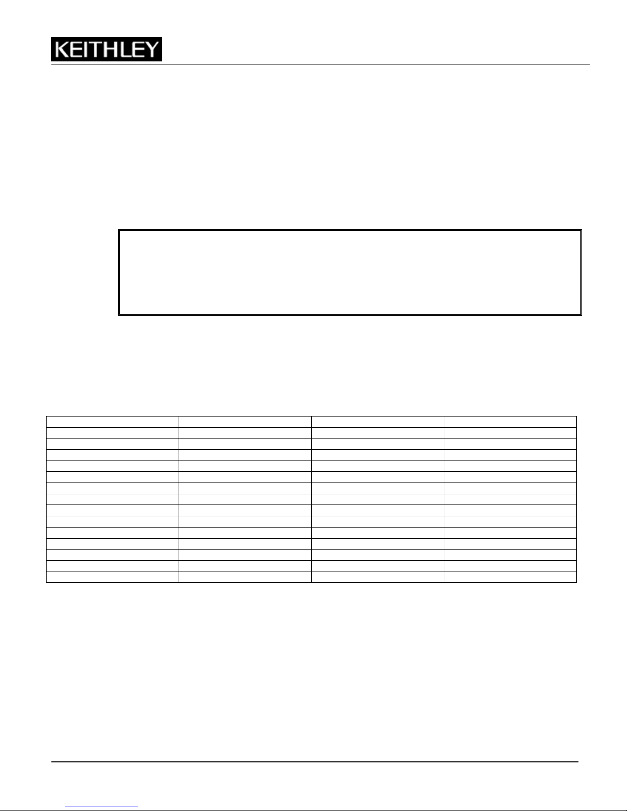
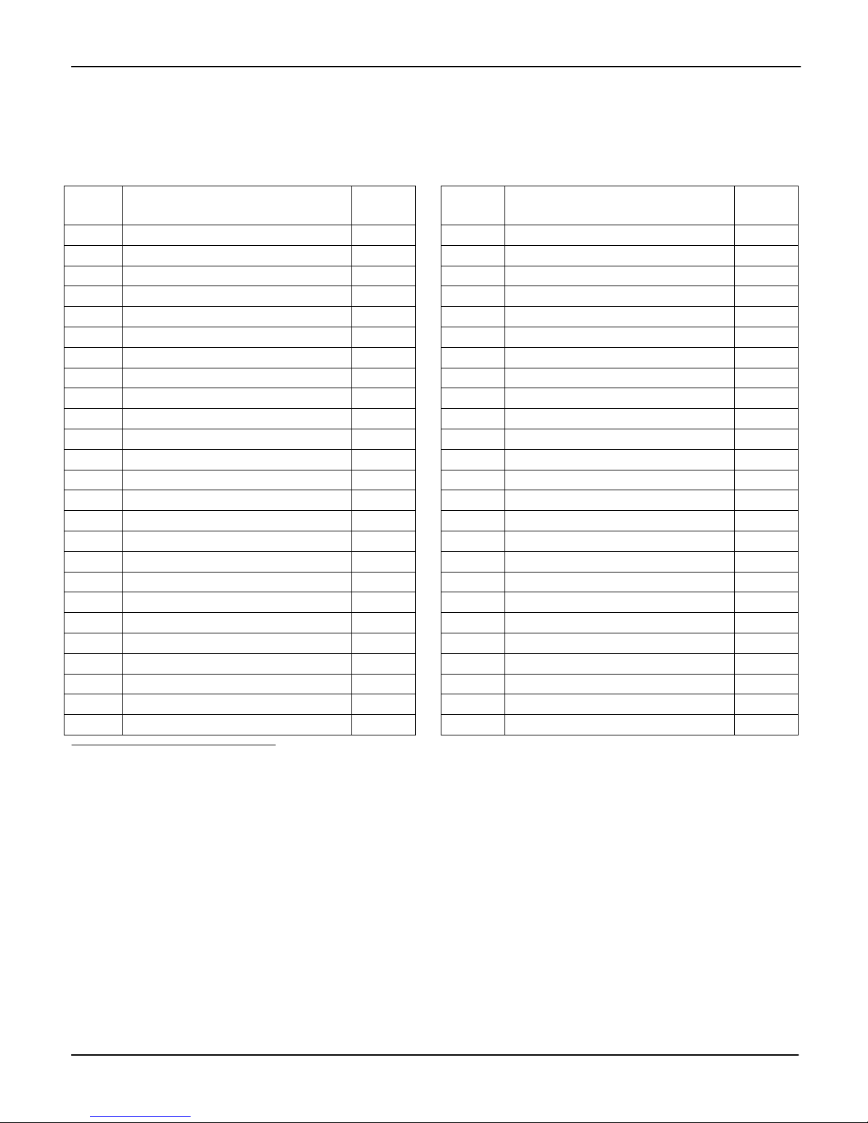
The following table lists available cable and connector kits, the number of conncetor pins for each kit, and cable
length (where applicable).
Table 1: Series 3700 cables and connector kits
Model number Number of pins Description Length
3720-MTC-1.5 78 Cable 1.5 m (5 ft)
3720-MTC-3 78 Cable 3 m (10 ft)
3721-MTC-1.5 50 Cable 1.5 m (5 ft)
3721-MTC-3 50 Cable 3 m (10 ft)
3722-MTC-1.5 104 Cable 1.5 m (5 ft)
3722-MTC-3 104 Cable 3 m (10 ft)
3722-MTC-1.5/MM 104 Cable 1.5 m (5 ft)
3722-MTC-3/MM 104 Cable 3 m (10 ft)
3732-MTC-1.5 78 Cable 1.5 m (5 ft)
3732-MTC-3 78 Cable 3 m (10 ft)
3790-KIT50-R 50 Connector Kit N/A
3791-KIT78-R 78 Connector Kit N/A
3792-KIT104-R 104 Connector Kit N/A
3792-KIT104-R/F 104 Connector Kit N/A
PA-949 R
ev. D / May 2011 1
Page 2
Series 3700 Cable and Connector Kits Installation Instructions
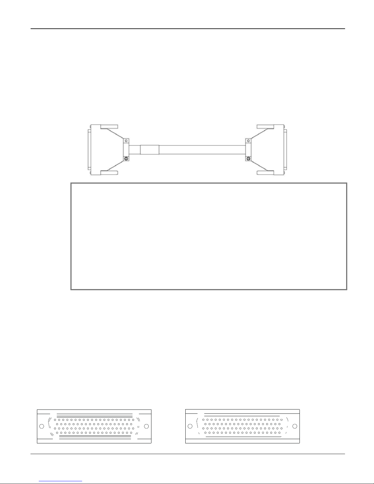
Model 3720-MTC-1.5 / 3.0
The Model 3720-MTC-1.5 / 3.0 cable is a 78-pin cable assembly (1.5m (5 ft) or 3.0m (10 ft) in length) terminated
with a male D-sub connector on one end and a female D-sub connector on the other end.
Figure 1: Model 3720-MTC-1.5 / 3.0 cable
WARNING Make sure the instrument that you are installing is in a powered-down state
with all cables unplugged. Failure to install an instrument in a discharged
state may cause personal injury or death from electrical shock. Do not
exceed the maximum specifications of the switching module.
To prevent electrical shock, observe the following safety precautions:
• Both ends of the cable must be connected before applying any power
to the system.
• Remove all power in the system before connecting the cable to a
switching module or external circuitry.
• Both D-sub connector shells of this cable must be connected to a
safety earth ground. A shock hazard exists when voltage levels greater
than 30V RMS, 42.4V peak, or 60V DC are present.
Cable maximum signal levels
The Model 3720-MTC-1.5 / 3.0 cable is rated for 300V DC or 300V RMS.
Maximum current rating
The Model 3720-MTC-1.5 / 3.0 cable maximum current ratings are as follows:
Single conductor: 4.4A
Multiple conductors: 2.2A per wire
Conductor gauge: 22 AWG
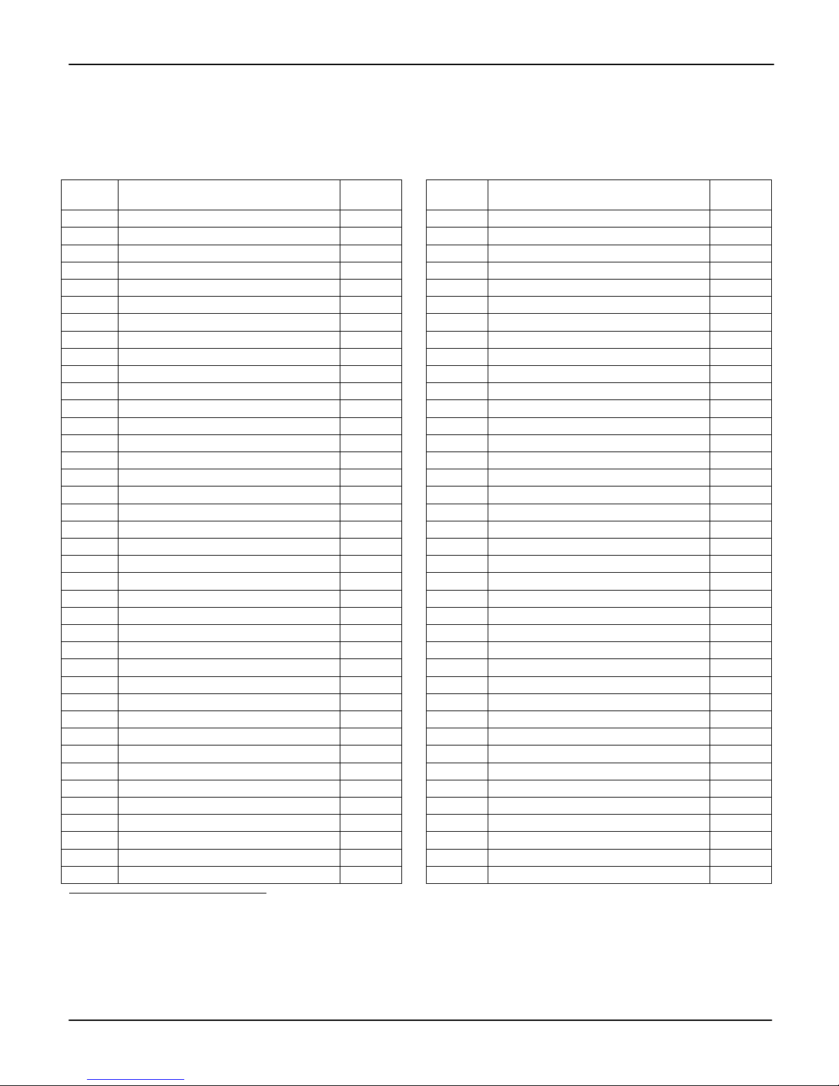
Pin number identification
Pin number identification for the Model 3720-MTC-1.5 / 3.0 cables are shown in Figure 2 and Table 2 below:
Figure 2: Model 3720-MTC-1.5 / 3.0 pin number identification
Male D-sub connector: Female D-sub connector:
1
21
40
60
2 PA-949 R
78
20
39
59
59
20
39
78
1
21
40
60
ev. D / May 2011
Page 3
Series 3700 Cable and Connector Kits Installation Instructions
Table 2: Model 3720-MTC-1.5 / 3.0 pin number identification
1
CONN
1 Pin #
1 Black 1 40 White / Red / Gray 40
2 Brown 2 41 White / Orange / Yellow 41
3 Red 3 42 White / Orange / Green 42
4 Orange 4 43 White / Orange / Blue 43
5 Yellow 5 44 White / Orange / Violet 44
6 Green 6 45 White / Orange / Gray 45
7 Blue 7 46 White / Yellow / Green 46
8 Violet 8 47 White / Yellow / Blue 47
9 Gray 9 48 White / Yellow / Violet 48
10 White 10 49 White / Yellow / Gray 49
11 White / Black 11 50 White / Green / Blue 50
12 White / Brown 12 51 White / Green / Violet 51
13 White / Red 13 52 White / Black / Orange / Yellow 52
14 White / Orange 14 53 N / C2 53
15 White / Yellow 15 54 N / C 54
16 White / Green 16 55 N / C 55
17 White / Blue 17 56 N / C 56
18 White / Violet 18 57 N / C 57
19 White / Gray 19 58 N / C 58
20 White / Black / Brown 20 59 N / C 59
21 White / Black / Red 21 60 White / Black / Orange / Green 60
22 White / Black / Orange 22 61 White / Black / Orange / Blue 61
23 White / Black / Yellow 23 62 White / Green / Gray 62
24 White / Black / Green 24 63 White / Blue / Violet 63
25 White / Black / Blue 25 64 White / Blue / Gray 64
26 White / Black / Violet 26 65 White / Violet / Gray 65
27 White / Black / Grey 27 66 White / Black / Brown / Red 66
28 White / Brown / Red 28 67 White / Black / Brown / Orange 67
29 White / Brown / Orange 29 68 White / Black / Brown / Yellow 68
30 White / Brown / Yellow 30 69 White / Black / Brown / Green 69
31 White / Brown / Green 31 70 White / Black / Brown / Blue 70
32 White / Brown / Blue 32 71 White / Black / Brown / Violet (s) 71
33 White / Brown / Violet 33 72 N / C 72
34 White / Brown / Gray 34 73 White / Black / Brown / Gray 73
35 White / Red / Orange 35 74 White / Black / Red / Yellow 74
36 White / Red / Yellow 36 75 White / Black / Red / Green 75
37 White / Red / Green 37 76 White / Black / Red / Blue 76
38 White / Red / Blue 38 77 White / Black / Red / Violet 77
39 White / Red / Violet (s)3 39 78 White / Black / Red / Gray 78
Color
CONN 2
Pin #
CONN 1
Pin #
Color
CONN 2
Pin #
1
Connect drain wire to shield at both ends.
2
N/C = Not connected
3
(s) = Spare.
PA-949 R
ev. D / May 2011 3
Page 4
Series 3700 Cable and Connector Kits Installation Instructions
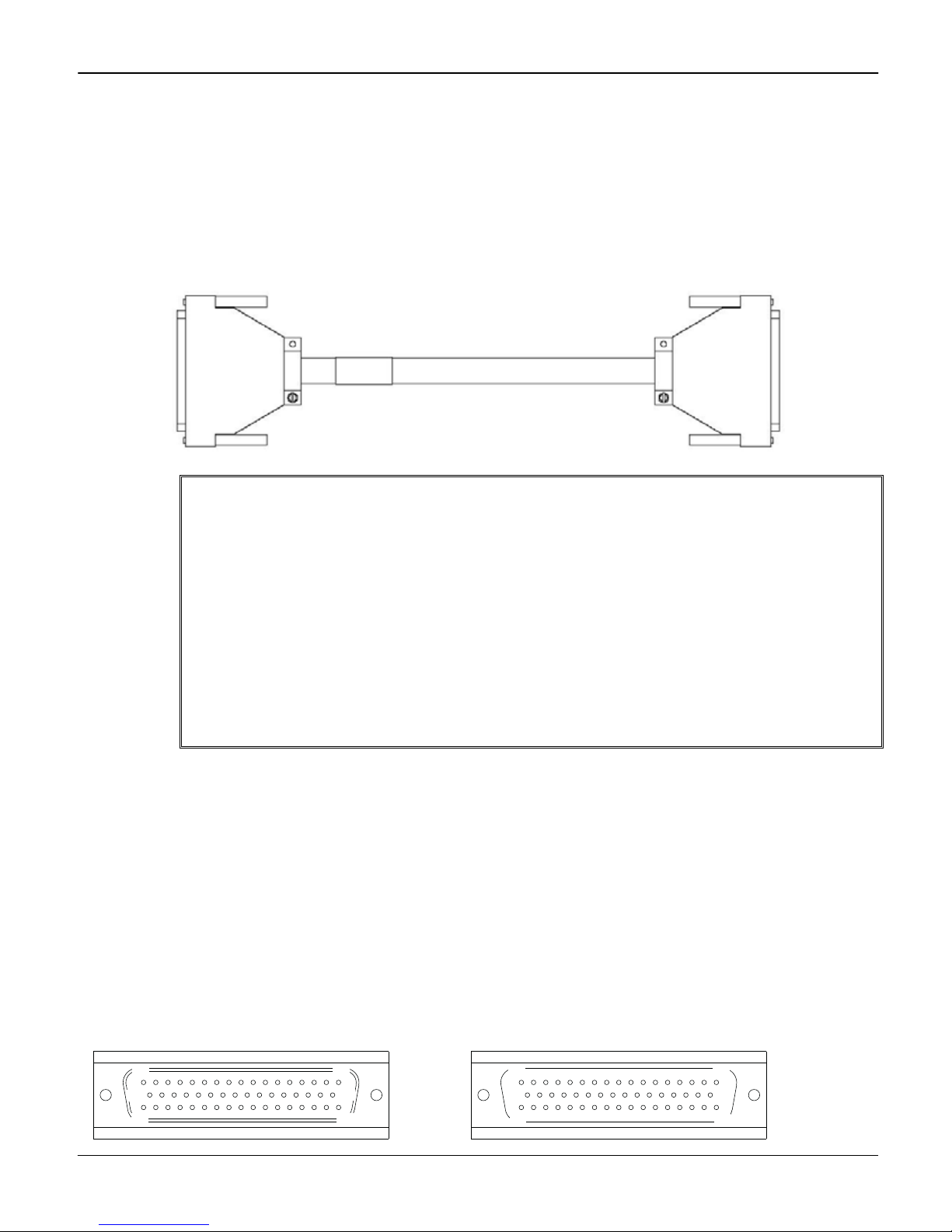
Model 3721-MTC-1.5 / 3.0
The Model 3721-MTC-1.5 / 3.0 cable is a 50-pin cable assembly (1.5m (5 ft) or 3.0m (10 ft) in length) terminated
with a male D-sub connector on one end and a female D-sub connector on the other end.
Figure 3: Model 3721-MTC-1.5 / 3.0 cable
WARNING Make sure the instrument that you are installing is in a powered-down state
with all cables unplugged. Failure to install an instrument in a discharged
state may cause personal injury or death from electrical shock. Do not
exceed the maximum specifications of the switching module.
To prevent electrical shock, observe the following safety precautions:
• Both ends of the cable must be connected before applying any power
to the system.
• Remove all power in the system before connecting the cable to a
switching module or external circuitry.
• Both D-sub connector shells of this cable must be connected to a
safety earth ground. A shock hazard exists when voltage levels greater
than 30V RMS, 42.4V peak, or 60V DC are present.
Cable maximum signal levels
The Model 3721-MTC-1.5 / 3.0 cable is rated for 300V DC or 300V RMS.
Maximum current rating
The Model 3721-MTC-1.5 / 3.0 cable maximum current ratings are as follows:
Single conductor: 4.4A
Multiple conductors: 2.2A per wire
Conductor gauge: 22 AWG
Pin number identification
Pin number identification for the Model 3721-MTC-1.5 / 3.0 D-sub connectors are shown in Figure 4 and Table 3 below:
Figure 4: Model 3721-MTC-1.5 / 3.0 pin number identification
Male D-sub connector: Female D-sub connector:
1
18
34
4 PA-949 R
17
50
33
33
17
50
34
1
18
ev. D / May 2011
Page 5
Series 3700 Cable and Connector Kits Installation Instructions
Table 3: Model 3721-MTC-1.5 / 3.0 pin number identification4
CONN 1
Pin #
1 Black 1 26 Orange / Black / White 26
2 White 2 27 Blue / Black / White 27
3 Red 3 28 Black / Red / Green 28
4 Green 4 29 White / Red / Green 29
5 Orange 5 30 Red / Black / Green 30
6 Blue 6 31 Green / Black / Orange 31
7 White / Black 7 32 Orange / Black / Green 32
8 Red / Black 8 33 Blue / White / Orange 33
9 Green / Black 9 34 Black / White / Orange 34
10 Orange / Black 10 35 White / Red / Orange 35
11 Blue / Black 11 36 Orange / White / Blue 36
12 Black / White 12 37 White / Red / Gblue 37
13 Red / White 13 38 Black / White / Green 38
14 Green / White 14 39 White / Black / Green 39
15 Blue / White 15 40 Red / White / Green 40
16 Black / Red 16 41 Green / White / Blue 41
17 White / Red 17 42 Orange / Red / Green 42
18 Orange / Red 18 43 Blue / Red / Green 43
19 Blue / Red 19 44 Black / White / Blue 44
20 Red / Green 20 45 White / Black / Blue 45
21 Orange / Green 21 46 Red / White / Blue 46
22 Black / White / Red 22 47 Green / Orange / Red 47
23 White / Black / Red 23 48 Orange / Red / Blue 48
24 Red / Black / White 24 49 Blue / Orange / Red 49
25 Green / Black / White 25 50 Black / Orange / Red 50
Color
CONN 2
Pin #
CONN 1
Pin #
Color
4
Connect drain wire to shield at both ends.
CONN 2
Pin #
PA-949 R
ev. D / May 2011 5
Page 6

Series 3700 Cable and Connector Kits Installation Instructions
Model 3722-MTC-1.5 / 3.0
The Model 3722-MTC-1.5 / 3.0 cable is a 104-pin cable assembly (1.5m (5 ft) or 3.0m (10 ft) in length) terminated
with a male D-sub connector on one end and a female D-sub connector on the other end.
Figure 5: Model 3722-MTC-1.5 / 3.0 cable
WARNING Make sure the instrument that you are installing is in a powered-down state
with all cables unplugged. Failure to install an instrument in a discharged
state may cause personal injury or death from electrical shock. Do not
exceed the maximum specifications of the switching module.
To prevent electrical shock, observe the following safety precautions:
• Both ends of the cable must be connected before applying any power
to the system.
• Remove all power in the system before connecting the cable to a
switching module or external circuitry.
• Both D-sub connector shells of this cable must be connected to a
safety earth ground. A shock hazard exists when voltage levels greater
than 30V RMS, 42.4V peak, or 60V DC are present.
Cable maximum signal levels
The Model 3722-MTC-1.5 / 3.0 cable is rated for 300V DC or 300V RMS.
Maximum current rating
The Model 3722-MTC-1.5 / 3.0 cable maximum current ratings are as follows:
Single conductor: 4.4A
Multiple conductors: 2.2A per wire
Conductor gauge: 24 AWG
Pin number identification
Pin number identification for the Model 3722-MTC-1.5 / 3.0 D-sub connectors are shown in Figure 6 and Table 4 below:
Figure 6: Model 3722-MTC-1.5 / 3.0 pin number identification
Male D-sub connector: Female D-sub connector:
21
42
63
84
104
104
21
42
63
84
1
22
43
64
85
6 PA-949 R
1
22
43
64
85
ev. D / May 2011
Page 7

Series 3700 Cable and Connector Kits Installation Instructions
Model 3722-MTC-1.5/MM / 3/MM
The Model 3722-MTC-1.5/MM / 3/MM cable is a 104-pin cable assembly (1.5m (5 ft) or 3.0m (10 ft) in length)
terminated with a male D-sub connector on each end.
Figure 7: Model 3722-MTC-1.5/MM / 3/MM cable
WARNING Make sure the instrument that you are installing is in a powered-down state
with all cables unplugged. Failure to install an instrument in a discharged
state may cause personal injury or death from electrical shock. Do not
exceed the maximum specifications of the switching module.
To prevent electrical shock, observe the following safety precautions:
• Both ends of the cable must be connected before applying any power
to the system.
• Remove all power in the system before connecting the cable to a
switching module or external circuitry.
• Both D-sub connector shells of this cable must be connected to a
safety earth ground. A shock hazard exists when voltage levels greater
than 30V RMS, 42.4V peak, or 60V DC are present.
Cable maximum signal levels
The Model 3722-MTC-1.5/MM / 3/MM cable is rated for 300V DC or 300V RMS.
Maximum current rating
The Model 3722-MTC-1.5/MM / 3/MM cable maximum current ratings are as follows:
Single conductor: 4.4A
Multiple conductors: 2.2A per wire
Conductor gauge: 24 AWG
Pin number identification
Pin number identification for the Model 3722-MTC-1.5/MM / 3/MM D-sub connectors are shown in Figure 8 and Table 4
below
:
Figure 8: Model 3722-MTC-1.5/MM / 3/MM pin number identification
Male D-sub connector: Male D-sub connector:
104
21
84
42
63
1
22
43
64
85
1
22
43
64
85
PA-949 R
ev. D / May 2011 7
104
21
42
63
84
Page 8

Series 3700 Cable and Connector Kits Installation Instructions
Table 4: Model 3722-MTC-1.5 / 3.0 and Model 3722-MTC-1.5/MM / 3/MM pin number identification5
CONN 1 CONN 2
First color pin # Second color pin #
1 2 Blue paired w/ White 1 2
3 4 Orange paired w/ White 3 4
5 6 Green paired w/ White 5 6
7 8 Brown paired w/ White 7 8
10 11 Slate paired w/ White 10 11
12 13 Blue / White Striped paired w/ White 12 13
14 35 Blue / Orange Striped paired w/ White 14 35
15 16 Blue / Green Striped paired w/ White 15 16
17 18 Blue / Brown Striped paired w/ White (s) 17 18
19 20 Blue / Slate Striped paired w/ White 19 20
21 42 Orange / White Striped paired w/ White 21 42
22 23 Orange / Green Striped paired w/ White 22 23
24 25 Orange / Brown Striped paired w/ White 24 25
26 27 Orange / Slate Striped paired w/ White 26 27
28 29 Green / White Striped paired w/ White 28 29
33 34 Green / Brown Striped paired w/ White 33 34
36 37 Green / Slate Striped paired w/ White 36 37
38 39 Brown / White Striped paired w/ White 38 39
40 41 Brown / Slate Striped paired w/ White 40 41
43 44 Slate / White Striped paired w/ White 43 44
45 46 Blue paired w/ Red 45 46
47 48 Orange paired w/ Red 47 48
49 50 Green paired w/ Red 49 50
51 52 Brown paired w/ Red 51 52
53 54 Slate paired w/ Red 53 54
55 56 Blue / White Striped paired w/ Red 55 56
57 58 Blue / Orange Striped paired w/ Red 57 58
59 80 Blue / Green Striped paired w/ Red 59 80
60 61 Blue / Brown Striped paired w/ Red 60 61
62 63 Blue / Slate Striped paired w/ Red 62 63
64 65 Orange / White Striped paired w/ Red 64 65
66 67 Orange / Green Striped paired w/ Red 66 67
68 69 Orange / Brown Striped paired w/ Red 68 69
70 71 Orange / Slate Striped paired w/ Red 70 71
72 73 Green / White Striped paired w/ Red 72 73
74 75 Green / Brown Striped paired w/ Red 74 75
76 77 Green / Slate Striped paired w/ Red 76 77
78 79 Brown / White Striped paired w/ Red 78 79
81 82 Brown / Slate Striped paired w/ Red 81 82
83 84 Slate / White Striped paired w/ Red 83 84
85 86 Blue paired w/ Black 85 86
87 88 Orange paired w/ Black 87 88
89 90 Gree n paired w/ Black 89 90
91 92 Brown paired w/ Black 91 92
93 94 Slate paired w/ Black 93 94
95 96 Blue / White Striped paired w/ Black 95 96
97 98 Blue / Orange Striped paired w/ Black 97 98
99 100 Blue / Green Striped paired w/ Black 99 100
101 102 Blue / Brown Striped paired w/ Black 101 102
103 104 Blue / Slate Striped paired w/ Black 103 104
5
Connect drain wire to shield at both ends.
6
Not connected: 9, 30, 31, 32
Paired wire colors6
First color pin # Second color pin #
8 PA-949 R
ev. D / May 2011
Page 9

Series 3700 Cable and Connector Kits Installation Instructions
Model 3732-MTC-1.5 / 3.0
The Model 3732-MTC-1.5 / 3.0 cable is a 78-pin cable assembly (1.5m (5 ft) or 3.0m (10 ft) in length) terminated
with a male D-sub connector on one end and a female D-sub connector on the other end.
Figure 2: Model 3732-MTC-1.5 / 3.0 cable
WARNING Make sure the instrument that you are installing is in a powered-down state
with all cables unplugged. Failure to install an instrument in a discharged
state may cause personal injury or death from electrical shock. Do not
exceed the maximum specifications of the switching module.
To prevent electrical shock, observe the following safety precautions:
• Both ends of the cable must be connected before applying any power
to the system.
• Remove all power in the system before connecting the cable to a
switching module or external circuitry.
• Both D-sub connector shells of this cable must be connected to a
safety earth ground. A shock hazard exists when voltage levels greater
than 30V RMS, 42.4V peak, or 60V DC are present.
Cable maximum signal levels
The Model 3732-MTC-1.5 / 3.0 cable is rated for 300V DC or 300V RMS.
Maximum current rating
The Model 3732-MTC-1.5 / 3.0 cable maximum current ratings are as follows:
Single conductor: 4.4A
Multiple conductors: 2.2A per wire
Conductor gauge: 22 AWG
Pin number identification
Pin number identification for the Model 3732-MTC-1.5 / 3.0 cables are shown in Figure 2 and Table 5 below:
Figure 2: Model 3732-MTC-1.5 / 3.0 pin number identification
Male D-sub connector: Female D-sub connector:
1
21
40
60
PA-949 R
ev. D / May 2011 9
78
20
39
59
59
20
39
78
1
21
40
60
Page 10

Series 3700 Cable and Connector Kits Installation Instructions
Table 5: Model 3732-MTC-1.5 / 3.0 pin number identification
7
CONN
1 Pin #
1 Black 1 40 White / Red / Gray 40
2 Brown 2 41 White / Orange / Yellow 41
3 Red 3 42 White / Orange / Green 42
4 Orange 4 43 White / Orange / Blue 43
5 Yellow 5 44 White / Orange / Violet 44
6 Green 6 45 White / Orange / Gray 45
7 Blue 7 46 White / Yellow / Green 46
8 Violet 8 47 White / Yellow / Blue 47
9 Gray 9 48 White / Yellow / Violet 48
10 White 10 49 White / Yellow / Gray 49
11 White / Black 11 50 N / C8 50
12 White / Brown 12 51 N / C 51
13 White / Red 13 52 N / C 52
14 White / Orange 14 53 White / Green / Blue 53
15 White / Yellow 15 54 White / Green / Violet 54
16 White / Green 16 55 White / Blue / Orange / Yellow 55
17 White / Blue 17 56 N / C 56
18 White / Violet 18 57 N / C 57
19 White / Gray 19 58 N / C 58
20 White / Black / Brown 20 59 N / C 59
21 White / Black / Red 21 60 White / Black / Orange / Green 60
22 White / Black / Orange 22 61 White / Black / Orange / Blue 61
23 White / Black / Yellow 23 62 White / Green / Gray 62
24 White / Black / Green 24 63 White / Blue / Violet 63
25 White / Black / Blue 25 64 White / Blue / Gray 64
26 White / Black / Violet 26 65 White / Violet / Gray 65
27 White / Black / Grey 27 66 White / Black / Brown / Red 66
28 White / Brown / Red 28 67 White / Black / Brown / Orange 67
29 White / Brown / Orange 29 68 White / Black / Brown / Yellow 68
30 White / Brown / Yellow 30 69 White / Black / Brown / Green 69
31 White / Brown / Green 31 70 White / Black / Brown / Blue 70
32 White / Brown / Blue 32 71 White / Black / Brown / Violet (s) 71
33 White / Brown / Violet 33 72 White / Black / Red / Green 72
34 White / Brown / Gray 34 73 White / Black / Brown / Gray 73
35 White / Red / Orange 35 74 White / Black / Red / Yellow 74
36 White / Red / Yellow 36 75 N / C 75
37 White / Red / Green 37 76 White / Black / Red / Blue 76
38 White / Red / Blue 38 77 White / Black / Red / Violet 77
39 White / Red / Violet (s)9 39 78 White / Black / Red / Gray 78
7
Connect drain wire to shield at both ends.
8
N/C = Not connected.
9
(s) = Spare.
Color
CONN 2
Pin #
CONN 1
Pin #
Color
CONN 2
Pin #
PA-949 Rev. D / May 2011
10
Page 11

Series 3700 Cable and Connector Kits Installation Instructions
Model 3790-KIT50-R
The Model 3790-KIT50-R kit is a 50-pin solder-cup connector kit terminated with a female D-sub connector.
Figure 9: 50-pin female D-sub connector kit assembled
WARNING Make sure the instrument that you are installing is in a powered-down state
with all cables unplugged. Failure to install an instrument in a discharged
state may cause personal injury or death from electrical shock. Do not
exceed the maximum specifications of the switching module.
To prevent electrical shock, observe the following safety precautions:
• Both ends of the cable must be connected before applying any power
to the system.
• Remove all power in the system before connecting the cable to a
switching module or external circuitry.
• Both D-sub connector shells of this cable must be connected to a
safety earth ground. A shock hazard exists when voltage levels greater
than 30V RMS, 42.4V peak, or 60V DC are present.
Maximum signal levels
The Model 3790-KIT50-R connector kit is rated for 300V RMS.
Maximum current rating
The Model 3790-KIT50-R connector kit maximum current is 7.5A.
Pin number identification
Pin number identification for the Model 3790-KIT50-R D-sub connector is shown in Figure 10 below:
Figure 10: Model 3790-KIT50-R kit pin number identification
Female D-sub connector:
17
33
50
1
18
34
Contacts
The contact is 20 AWG maximum.
PA-949 Rev. D / May 2011 11
Page 12

Series 3700 Cable & Connector Instructions
Model 3791-KIT78-R
The Model 3791-KIT78-R kit is a 78-pin solder-cup connector kit terminated with a female D-sub connector.
Figure 11: 78-pin female D-sub connector kit assembled
WARNING Make sure the instrument that you are installing is in a powered-down state
with all cables unplugged. Failure to install an instrument in a discharged
state may cause personal injury or death from electrical shock. Do not
exceed the maximum specifications of the switching module.
To prevent electrical shock, observe the following safety precautions:
• Both ends of the cable must be connected before applying any power
to the system.
• Remove all power in the system before connecting the cable to a
switching module or external circuitry.
• Both D-sub connector shells of this cable must be connected to a
safety earth ground. A shock hazard exists when voltage levels greater
than 30V RMS, 42.4V peak, or 60V DC are present.
Maximum signal level
The Model 3791-KIT78-R connector kit is rated for 300V RMS.
Maximum current rating
The Model 3791-KIT78-R connector kit maximum current is 5.0A.
Pin number identification
Pin number identification for the Model 3791-KIT78-R D-sub connector is shown in Figure 12 below:
Figure 12: Model 3791-KIT78-R kit pin number identification
Female D-sub connector:
20
39
59
78
1
21
40
60
Contacts
The contact is 22 AWG maximum, and an insertion tool (not included) is required (part number 3791-CIT).
12 PA-949 Rev. D / May 2011
Page 13

Series 3700 Cable & Connector Instructions
Model 3792-KIT104-R
The Model 3792-KIT104-R kit is a 104-pin solder-cup connector kit terminated with a male D-sub connector.
Figure 13: 104-pin male D-sub connector kit assembled
WARNING Make sure the instrument that you are installing is in a powered-down state
with all cables unplugged. Failure to install an instrument in a discharged
state may cause personal injury or death from electrical shock. Do not
exceed the maximum specifications of the switching module.
To prevent electrical shock, observe the following safety precautions:
• Both ends of the cable must be connected before applying any power
to the system.
• Remove all power in the system before connecting the cable to a
switching module or external circuitry.
• Both D-sub connector shells of this cable must be connected to a
safety earth ground. A shock hazard exists when voltage levels greater
than 30V RMS, 42.4V peak, or 60V DC are present.
Maximum signal level
The Model 3792-KIT104-R connector kit is rated for 300V RMS.
Maximum current rating
The Model 3792-KIT104-R connector kit maximum current is 5.0A.
Pin number identification
Pin number identification for the Model 3792-KIT104-R D-sub connector is shown Figure 14 below:
Figure 14: Model 3792-KIT104-R kit pin number identification
Male D-sub connector:
104
21
42
63
84
1
22
43
64
85
Contacts
The contact is 22 AWG maximum, and an insertion tool (not included) is required (part number 3791-CIT).
PA-949 Rev. D / May 2011 13
Page 14

Series 3700 Cable & Connector Instructions
Model 3792-KIT104-R/F
The Model 3792-KIT104-R/F kit is a 104-pin solder-cup connector kit terminated with a female D-sub connector.
Figure 15: 104-pin female D-sub connector kit assembled
WARNING Make sure the instrument that you are installing is in a powered-down state
with all cables unplugged. Failure to install an instrument in a discharged
state may cause personal injury or death from electrical shock. Do not
exceed the maximum specifications of the switching module.
To prevent electrical shock, observe the following safety precautions:
• Both ends of the cable must be connected before applying any power
to the system.
• Remove all power in the system before connecting the cable to a
switching module or external circuitry.
• Both D-sub connector shells of this cable must be connected to a
safety earth ground. A shock hazard exists when voltage levels greater
than 30V RMS, 42.4V peak, or 60V DC are present.
Maximum signal level
The Model 3792-KIT104-R/F connector kit is rated for 300V RMS.
Maximum current rating
The Model 3792-KIT104-R/F connector kit maximum current is 5.0A.
Pin number identification
Pin number identification for the Model 3792-KIT104-R/F D-sub connector is shown in Figure 16 below:
Figure 16: Model 3792-KIT104-R/F kit pin number identification
Contacts
The contact is 22 AWG maximum, and an insertion tool (not included) is required (part number 3791-CIT).
14 PA-949 Rev. D / May 2011
Female D-sub connector:
21
42
63
84
104
85
1
22
43
64
 Loading...