

Page 1
Number 2208
Application Note
Series
Solutions for Production Testing
of Connectors
Introduction
As electronics have become increasingly pervasive, the
importance of electrical connectors has also increased dramatically. Quality connectors are vital to ensuring overall product
reliability in applications ranging from motor vehicles to transatlantic telecom systems. This application note addresses many
of the issues involved in implementing a connector characterization system.
The degree and type of electrical testing that connectors
undergo typically depends on how crucial they are to the overall
performance of the systems in which they’re installed. Stringent
electrical tests are often specified when high reliability is
required. Obviously, connectors used in international telecommunications systems are more crucial than the serial port connector
on the back of a desktop personal computer.
The two most commonly measured parameters in connector testing are isolation and continuity. Isolation measurements
are usually performed between each of the connector pins or
between the pins and the outer shell of the connector. Also,
during connector manufacturing and testing (both mechanical
and environmental testing), the continuity may become
compromised. Testing the continuity of each pin ensures that
once the connector is installed, the electrical signals will be
transmitted properly.
Test Description
Connector Shell
become shorted tomorrow in an environment with high heat and
vibration, such as under the hood of a car.
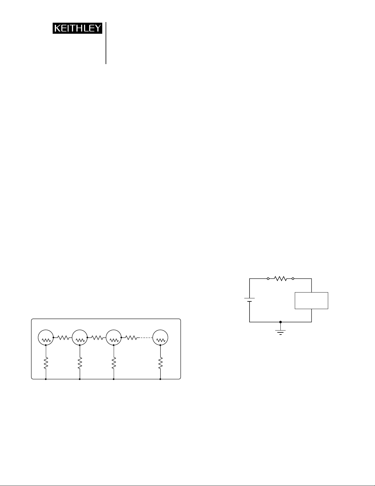
Isolation is typically tested by applying a voltage across
two pins in a connector and measuring the resulting current that
flows between them. The corresponding resistance from the test
is compared to a predetermined threshold value. If the resistance
level is too low, the connector is rejected. Common threshold
levels range from 1MΩ to 1TΩ. The isolation resistance is
shown as R
in Figure 1.
iso
When testing very high ohmic devices, the measured
resistance may change significantly in response to a change in
the applied voltage, an effect known as the voltage coefficient of
resistance. This effect makes it preferable to test high value
resistors with the constant voltage, measure current method. The
actual test voltage chosen depends on the capabilities of the
instrumentation and the degree of current measurement sensitivity available. For a given resistance value, a higher voltage will
result in a higher current signal, which can be measured with
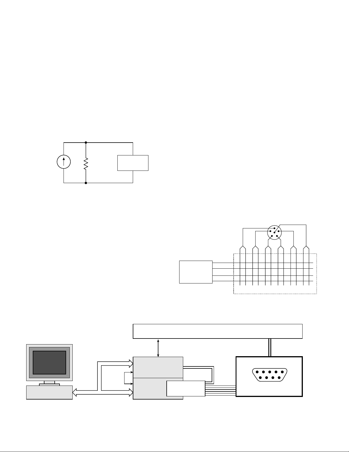
higher resolution. Figure 2 illustrates the constant voltage
method for measuring high resistances.
R
Isolation
HI
Voltage
Source
Ammeter
LO
R
pin1
R
iso
Figure 1. Electrical equivalent of a connector showing pin continuity and
isolation resistance.
R
pin2
R
iso
R
iso
R
pin3
R
iso
R
iso
R
iso
R
pinX
R
iso
Isolation (Insulation) Resistance
Essentially, the isolation measurement verifies that none of the
connector pins are shorted to each other. Given today’s evershrinking circuit geometry and the higher frequencies of electronics, isolation is an important consideration for reliability and
minimizing crosstalk. Aconnector with no shorts today may
Figure 2. Constant Voltage Method for Measuring High Resistance.
Pin Continuity
As long-term performance of connectors becomes increasingly
important, the continuity performance from the input to the output of the connector will also become more important. Typically,
continuity is tested by sourcing a constant current through the
pin and measuring the corresponding voltage drop. Connector
pins are often made from metal alloys, so the measurement result
is a very low resistance value. Pin continuity is shown as R
Figure 1.
Using high currents to test continuity has two advantages.
First, using a sufficiently high test current ensures the resulting
voltage signal will be above the noise floor of the test system.
pin
in
Page 2
The ratio of the test current to the noise current will determine
the signal-to-noise ratio and accuracy of the continuity test.
Second, higher test currents can also serve as a stress test for
the connector. Often, the connector will be tested at a current
level higher than the rated current level in order to verify
performance margin.
If stress testing is unnecessary, a digital multimeter
(DMM) with low voltage noise can be used to measure the pin
resistance directly. Figure 3 illustrates how a current source and
voltmeter are used to measure resistance. Most instruments
designed to measure low resistances have a built-in current
source and voltmeter and can be configured to measure
resistance with one instrument bus command or button on the
front panel.
HI
Current
Source
Figure 3. Constant Current Method for Measuring Low Resistance.
R
Continuity
Voltmeter
LO
2400 can output 210V, while the 2410 is capable of 1100V. Both
supplies are limited to 22W. These output ranges mean that only
one measurement instrument is required for both isolation and
continuity measurements, which greatly reduces programming,
cabling, and potential error sources.
Connectors typically contain many pins, so many measurement channels are required to test each pin. The most costeffective way of adding measurement channels is to include
switching in the test system. When switching is added, the user
can connect the SourceMeter instrument to specific points on the
connector for testing while simultaneously isolating other points.
Also, if a PC is added to the system to control the instrument and
switching, the entire connector test assembly can be automated,
eliminating the need for constant operator oversight. Figure 4
illustrates a simple connector test configuration based on a
SourceMeter instrument.
A SourceMeter-based connector test system is both cost
effective and easy to implement in terms of cabling, programming, and complexity. Systems like this can typically resolve
signals as low as 10µ Ω and measure resistances as high as
20GΩ. Figure 5 demonstrates how the SourceMeter can be used
to test a connector.
Test System Option Descriptions
Single Meter Connector Test System
The 2400 Series of SourceMeter®instruments provides low
noise, bipolar constant current and voltage sources with precision
readback measurement capabilities. Creating a test program that
switches between constant current and voltage modes is relatively straightforward and seamless. All models in the SourceMeter
family are programmed in exactly the same manner. The only
differences between these instruments are the differing dynamic
ranges of their voltage and current outputs.
The Model 2400 and Model 2410 are the most popular
choices for connector testing. Both can source up to 1A. The
Digital I/O Mechanical
Model 24XX
SourceMeter
Trigger
PC with
KPCI-488
GPIB
Link
Model 700X
Switch
Mainframe
Connector
Under Test
Sense HI
Model 24XX
SourceMeter
Figure 5. Electrical schematic for single-meter system.
Component Handler
7012 Matrix
Card
Force HI
Sense LO
Force LO
System
Cabling
123456
Model 7012 Matrix Card
Test Fixture
Connector
Under Test
Connection
Figure 4. Test system block diagram.
Page 3
High Resistance Test System
For many specialized connectors, the test specifications require
greater resolution at resistance levels >1GΩ. When accuracy is
critical when testing connectors at high resistances, the Model
6517A High Resistance Meter/Electrometer may be a more
appropriate solution than a SourceMeter instrument.
The 6517A can measure up to 10
voltage source (up to 1000V) and picoammeter. It can be easily
configured to measure the isolation resistance as shown in
Figure 2 with a 5
1
⁄2-digit picoamp measurement.
15
Ω by using its internal
can be pre-programmed with the desired test parameters and
sequence. With the external triggering, the instruments can execute the programmed test routine without PC intervention.
The multiplexer and the matrix are the two most common
switching topologies. Multiplexer switch cards are generally
used when one instrument is to be connected to many discrete
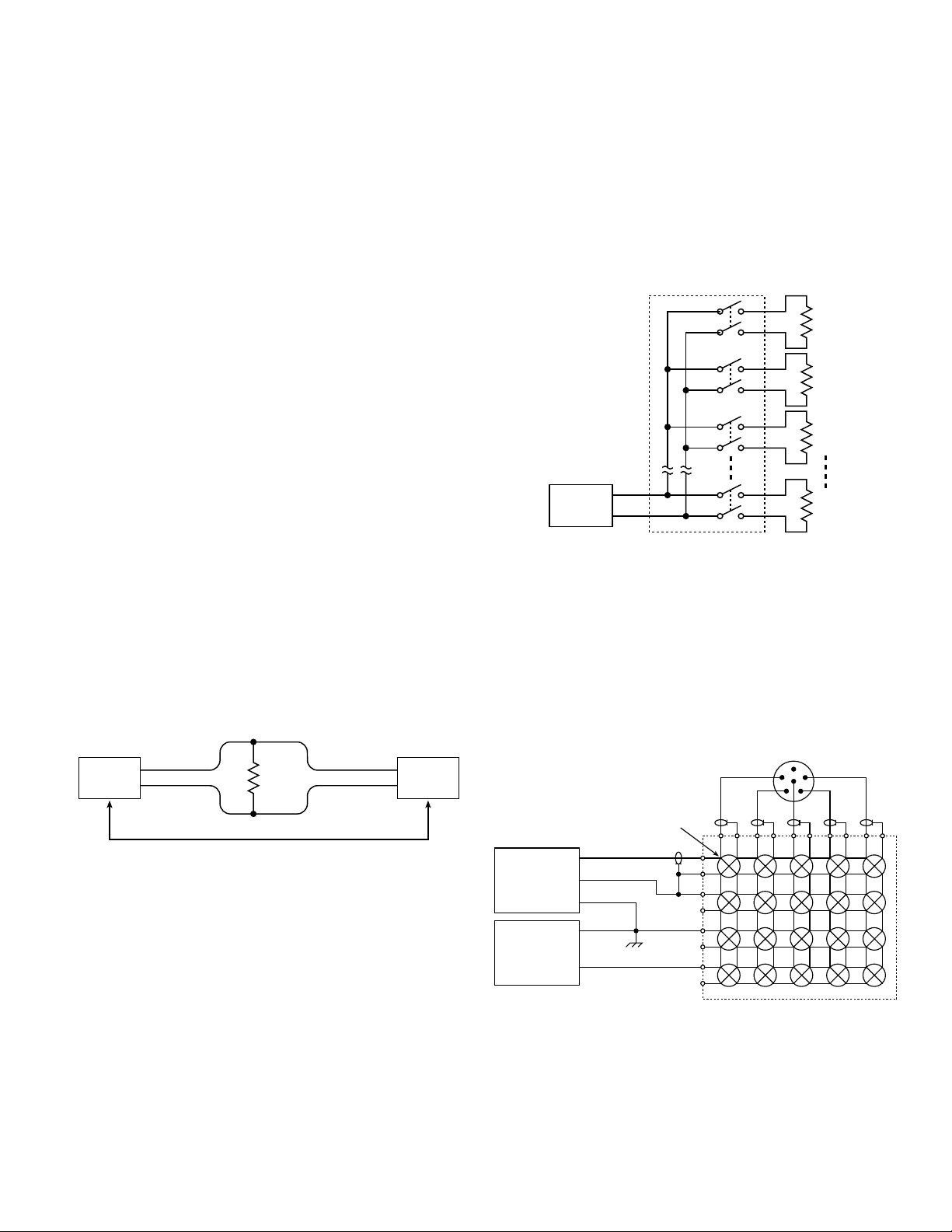
devices for testing. Figure 7 shows a simple multiplexer configuration in which resistors are connected across each relay. When
only one channel is closed, a device is connected to the meter
inputs and can be tested.
Low Resistance Test System
DMMs are often a convenient option for connector testing
because they are capable of sourcing current and measuring the
voltage drop across the connector pin. However, when testing
connector pin continuity, it is often impossible to force enough
current through the pin to produce a sufficient voltage drop to be
measured by a typical DMM. Most DMMs have a noise floor of
around 250nV. Realistically, the best DMM for low-noise, lowvoltage measurements, the Model 2010, can only be used for
measurements at or above 75nV or 500µΩ.
If a DMM can’t provide satisfactory measurement
performance, it is often necessary to use separate current source
and voltage measurement instrumentation. When coupled with a
Model 2400 SourceMeter, the Model 2182 Nanovoltmeter is
capable of measuring 100nΩ reliably. The Model 2182’s built-in
delta mode, used in combination with the 2400, provides the best
low ohms measurement for production applications (refer to the
section titled “Thermoelectric EMFs”). Figure 6 describes how
to connect the 2182 and 2400 to perform a continuity test on a
connector pin.
Model
2182
Ch. 1 HI
DUT
Ch. 1 LO
Output HI
Output LO
Model
24XX
R
40
R
39
R
38
R
1
Up to 40
differential
channels per
7011 Switch Card
Model
24XX
Quad 1x10 Multiplexer
Figure 7. Multiplexer configuration.
40
39
38
1
Model 7011
The matrix configuration provides the flexibility required
to test many different channel patterns. Matrices are useful for
connecting any point in the system to any other point in the
system. This configuration is also used when more than one
Connector
Under Test
Relay
Crosspoint
Model 8501 Trigger Link Cable
Figure 6. Delta Mode measurement using the Models 2182 and 2400.
Substituting the Model 2420 for the 2400 in the test will
allow testing pin continuity with source current up to 3A to
obtain a higher signal-to-noise ratio.
Switching Options
A switch card consists of relays that are configured to connect
measurement instrumentation to many test points in the circuit
under test. Each switch card is controlled by a switch mainframe
that can be programmed with a desired test sequence. Keithley
measurement instrumentation and switch mainframes have builtin trigger hardware (see the section titled “Trigger Link”) that
allows the measurement instrument to trigger the switch mainframe and vice versa. Both the instrument and switch mainframe
Ammeter HI
Model 6517A
Electrometer
Model 2010
DMM
Figure 8. Matrix configuration.
Guard
V-Source LO
LO
HI
Model 7153 High Voltage/Low Current Matrix Card
instrument is needed to test each device. Figure 8 shows a simple matrix configuration with two instruments. Two channels
must be closed in order to perform a measurement, but with this
layout, the instruments are able to test any possible combination
of resistance values.
Page 4
Methods and Techniques
Guarding
When testing multi-pin connectors, it is important not only to
guard the system cabling but also to guard the other pins that are
not being tested. When testing from one pin to another, the
resistance between the other pins and ground may affect the final
measurement. By connecting the guard output from the meter to
the other pins, the undesirable resistance and subsequent leakage
to ground is eliminated. Refer to Keithley’s Low Level
Measurements handbook for detailed information on guarding.
Trigger Link
The Trigger Link is a hardware handshake bus used by the
instruments to ensure proper test sequencing. It is a standard feature on all newer Keithley instruments, including the ones mentioned in this note. When the meter and switch mainframe are
connected via a Trigger Link cable, they can trigger each other to
allow faster test completion. This built-in bus eliminates the need
for direct PC control of most system synchronization functions.
When the Trigger Link function is used properly, the only functions the PC performs are initiating the test and retrieving data
from the system.
Typical Sources of Error
Noise
Noise can come from many sources in the production environment. When electrically charged objects, such as machinery,
electrical motors, or fluorescent lights are brought near an
uncharged object (i.e. the device under test), small, unwanted
voltages may be generated. To minimize the effects of this electrostatic interference, ensure all system cabling is properly
shielded.
All shields should be connected to a single ground point
to eliminate the possibility of creating ground loops, which can
also distort or alter test data. Whether the system cabling is
single- or multi-conductor, it is best to use one shield around the
wire bundle.
6517A
HI
Ammeter
Meter
Connect
Relay
V-Source
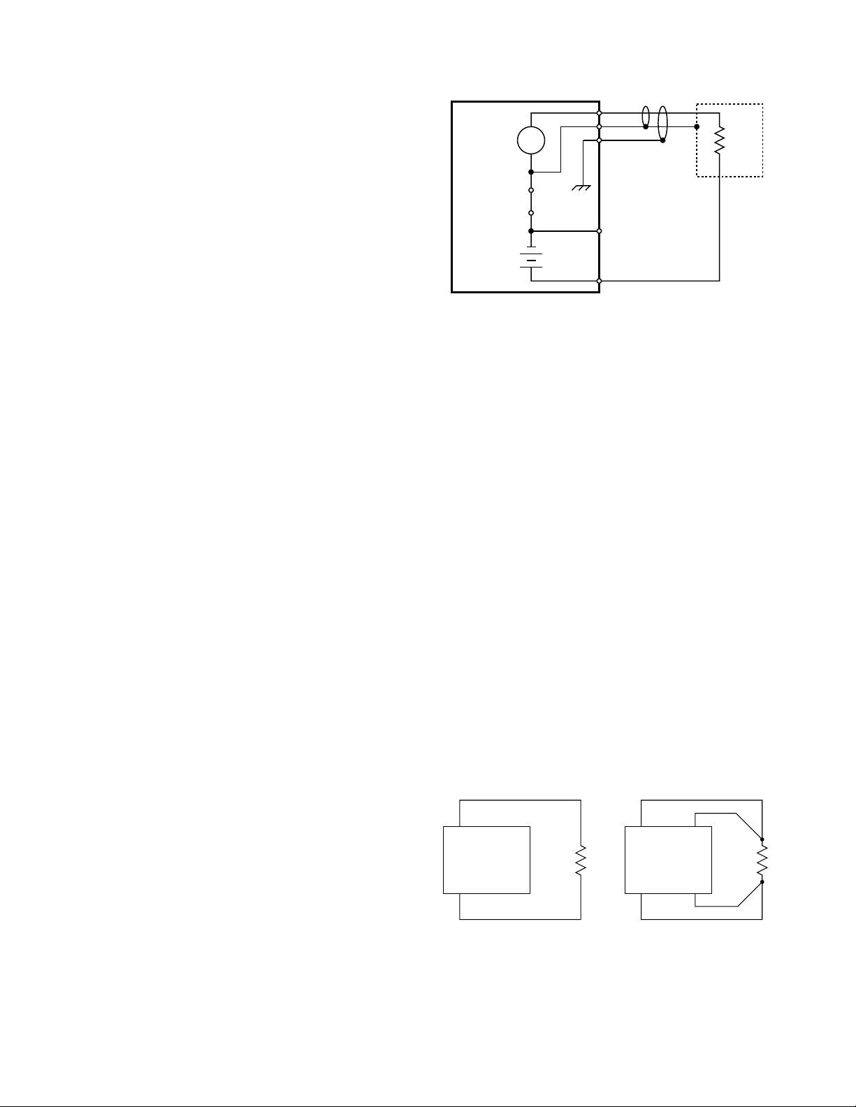
Figure 9. Model 6517A connections for making guarded Ohms measurement.
A
LO
Triax
Input
LO
HI
Shield
DUT
Cable Capacitance
The amount of capacitance in the test system cabling will determine the settling time required to obtain an accurate reading.
Settling time is determined by the system’s RC time constant, so
a large resistance value can result in significant settling times,
even with a relatively small capacitance value. For best accuracy,
let four to five time constants elapse before taking the measurement. Settling times can be reduced by keeping cable lengths as
short as possible, guarding the system properly, and using the
source voltage/measure current method of making high resistance measurements.
Lead Resistance
A common source of error for low impedance measurements is
the amount of series resistance present in the test leads connected to the DUT when only two test leads are used. Since the test
lead resistance is in series with the DUT, this resistance value is
added into the final measurement result. The series resistance is
especially detrimental for testing connector pins since the test
lead resistance may actually be greater than the pin itself, which
would result in more than 100% error. Figure 10a illustrates the
effect of series resistance when the current source and voltmeter
use the same pair of test leads.
Leakage Current
Stray or leakage current in cables and fixtures can be a source of
error in measurements of extremely low currents, such as for
high impedance devices or parameters. To minimize leakage current problems, the test fixture insulation must be made of materials with resistances much higher than the impedances being
tested. If proper care is not taken, some portion of the test current will flow through any low impedance path to ground, affecting measurement results.
An alternate method of reducing leakage currents is to
guard the test fixture from the measurement of the connector
under test. Figure 9 illustrates how to connect the 6517A
Electrometer to make a high resistance measurement properly to
minimize leakage current, cable capacitance, and noise.
Output
HI
Output
LO
Figure 10a. 2-Wire Measurement Figure 10b. 4-Wire Measurement
Model 24XX
SourceMeter
Sense
HI
Sense
LO
Output
HI
R
S
SourceMeter
Output
LO
Model 24XX
Sense
HI
Sense
LO
R
To eliminate lead resistance effects, the current source and
voltmeter must be separated and four wires used to connect to
the device. Figure 10b shows how the voltmeter senses the
voltage drop across the DUT without the effect of the lead
resistance.
S
Page 5

Thermoelectric EMFs
Thermoelectric EMFs may cause measurement problems, especially for low impedance measurements. The voltage drop across
low impedance devices is typically very small; therefore, thermoelectric EMFs may have sufficient magnitude to interfere with
the test signal. Instruments like those in the SourceMeter Series
can be programmed to cancel the effects of thermoelectric offsets
automatically through the offset compensation, or delta, method
of ohms measurement.
The delta method involves taking two measurements. The
first measurement is taken at the desired positive source level,
then the second is taken at the opposite source polarity. These
two measurements are then subtracted from each other and the
resulting resistance is calculated as follows:
V
– V
2
1
Delta Mode Ohms =
where: I1is the source current set to a specified positive value.
I
is the same current value as I1with opposite polarity.
2
V
is the voltage measured at I1.
1
V
is the voltage measured at I2.
2
________
I2– I
1
Example Program
Keithley has developed an example program in Visual Basic program that’s designed to perform the isolation and continuity tests
presented by the test system in Figure 8. To download a copy of
the program (connector.bas), visit Keithley's World Wide Web
site (http://www.keithley.com).
Note: The test programs provided are intended to illustrate the
concepts presented in this note. Some modifications may be
required to accommodate desired test parameters and timing.
Equipment List
Equipment needed to build the SourceMeter-based test system
shown in Figure 4:
1. Keithley Model 2400 SourceMeter
2. Keithley Model 7001 (or 7002) Switching Mainframe
3. Model 7012 4×10 General Purpose Matrix Switching
cards. Each card can accommodate up to 10 connector
pins.
4. PC with Model KPCI-488 IEEE-488 Interface Card
5. Two Model 7007 IEEE-488 Interface Cables
6. Model 8501 Trigger Link Cable
7. Test leads for connecting instrumentation to component
handler.
8. Digital I/O connections from handler to interface with 9pin male D-sub connector on SourceMeter
Equipment needed to build the connector test system illustrated
in Figure 8:
1. Keithley Model 6517A Electrometer/High Resistance
System
2. Keithley Model 2010 Low-Noise Multimeter
3. Keithley Model 7001 (or 7002) Switching Mainframe
4. Model 7153 4×5 High Voltage Low Current Matrix
Switching cards. Each card can accommodate up to 5 connector pins.
5. Model 7153-TRX cables for connecting to the 7153 card.
Two cables are required for each switch card in the system.
6. Model 237-TRX-T 3-slot Triax T adapters. Four adapters
are required for each switch card in the system.
7. PC with Model KPCI-488 IEEE-488 Interface Card
8. Three Model 7007 IEEE-488 Interface Cables
Alternative Solutions
Some types of connectors must be tested over wider voltage
and current ranges than those described here. Keithley
Application Note #2154, “Testing Devices with High Voltage
and High Current,” describes how to configure a test system
based on SourceMeter instruments that supports testing
isolation resistance up to 1100V and continuity up to 3A.
Page 6

Test System Safety
Many electrical test systems or instruments are capable of
measuring or sourcing hazardous voltage and power levels. It
is also possible, under single fault conditions (e.g., a programming error or an instrument failure), to output hazardous
levels even when the system indicates no hazard is present.
These high voltage and power levels make it essential
to protect operators from any of these hazards at all times.
Protection methods include:
• Design test fixtures to prevent operator contact with any
hazardous circuit.
• Make sure the device under test is fully enclosed to pro-
tect the operator from any flying debris. For example,
capacitors and semiconductor devices can explode if too
much voltage or power is applied.
• Double insulate all electrical connections that an operator
could touch. Double insulation ensures the operator is still
protected, even if one insulation layer fails.
• Use high-reliability, fail-safe interlock switches to discon-
nect power sources when a test fixture cover is opened.
• Where possible, use automated handlers so operators do
not require access to the inside of the test fixture or have a
need to open guards.
• Provide proper training to all users of the system so they
understand all potential hazards and know how to protect
themselves from injury.
It is the responsibility of the test system designers, integrators, and installers to make sure operator and maintenance
personnel protection is in place and effective.
Specifications are subject to change without notice.
All Keithley trademarks and trade names are the property of Keithley Instruments, Inc.
All other trademarks and trade names are the property of their respective companies.
Keithley Instruments,Inc. • 28775 Aurora Road • Cleveland, Ohio 44139 • 440-248-0400 • Fax: 440-248-6168 • www.keithley.com
BELGIUM: Keithley Instruments B.V. Bergensesteenweg 709 • B-1600 Sint-Pieters-Leeuw • 02/363 00 40 • Fax: 02/363 00 64
CHINA: Keithley Instruments China Yuan Chen Xin Building, Room 705 • 12 Yumin Road, Dewai, Madian • Beijing 100029 • 8610-62022886 • Fax: 8610-62022892
FRANCE: Keithley Instruments Sarl B.P. 60 • 3, allée des Garays • 91122 Palaiseau Cédex • 01 64 53 20 20 • Fax: 01 60 11 77 26
GERMANY: Keithley Instruments GmbH Landsberger Strasse 65 • D-82110 Germering • 089/84 93 07-40 • Fax: 089/84 93 07-34
GREAT BRITAIN: Keithley Instruments Ltd The Minster • 58 Portman Road • Reading, Berkshire RG30 1EA • 0118-9 57 56 66 • Fax: 0118-9 59 64 69
INDIA: Keithley Instruments GmbH Flat 2B, WILOCRISSA • 14, Rest House Crescent • Bangalore 560 001 • 91-80-509-1320/21 • Fax: 91-80-509-1322
ITALY: Keithley Instruments s.r.l. Viale S. Gimignano, 38 • 20146 Milano • 02/48 30 30 08 • Fax: 02/48 30 22 74
NETHERLANDS: Keithley Instruments B.V. Postbus 559 • 4200 AN Gorinchem • 0183-635333 • Fax: 0183-630821
SWITZERLAND: Keithley Instruments SA Kriesbachstrasse 4 • 8600 Dübendorf • 01-821 94 44 • Fax: 01-820 30 81
TAIWAN: Keithley Instruments Taiwan 1 Fl. 85 Po Ai Street • Hsinchu, Taiwan, R.O.C. • 886-3572-9077• Fax: 886-3572-9031
© Copyright 2000 Keithley Instruments, Inc. No. 2208
Printed in the U.S.A. 0200-10KGDA
 Loading...