

Page 1
Quick Start Guide
Understanding Basic Pulse Parameters
Setting your pulse parameters is a simple three step
process:
1. Choose your high level configuration with the menu keys.
2. Select the desired parameter with the Soft Keys.
3. Enter the desired value with the control knob or numerical
keypad.
Front Panel Setup Example
The following information demonstrates how to properly connect a
Keithley Instruments Model 340x Pulse Pattern Generator to an
oscilloscope
1
and how to navigate the front panel menu. The
information depicts how to adjust the most common pulse
parameters, including pulse amplitude, offset, width, period, and
leading and trailing edges.
Power On the Model 340x Pulse Pattern Generator:
1. Enable rear panel power switch (“ON” position).
2. Press front panel on/off switch.
Make Connections Between Pulse Generator &
Oscilloscope:
Connect a BNC-BNC cable between CH 1 output and CH 1 input of
the oscilloscope.
Configure Oscilloscope:
1. In trigger menu of scope:
a. Configure scope to trigger on rising edge of CH 1.
b. Set trigger level to +0.25V.
2. In vertical menu of scope:
a. Set input impedance to 50 or use a 50 feed through, such
as the Keithley Instruments Model 7755.
b. Set voltage scale to 500mV/division.
3. In Horizontal menu of scope, adjust the time scale to 400ns.
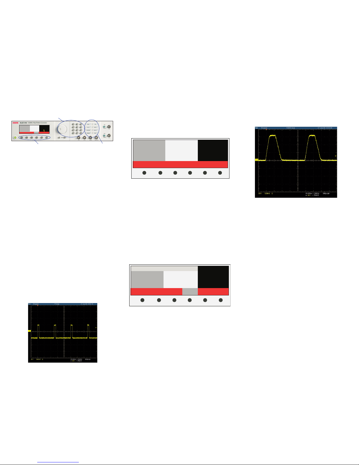
Turn on output Channel 1 of the pulse generator by pressing the CH
1 Enable button and verify that you have the following signal:
Adjust Output Pulse:
Unit should power up in “Mode” display window.
1. Press “Pulse” soft key.
2. Press VOLTS menu key.
3. Verify Channel 1 is selected. (NOTE: The dark gray area
should appear on left side of display and a “1” should appear in
the top left corner of display.)
4. Set amplitude to 1.50Vpp:
a. Press “Ampl” soft key. If “Ampl” soft key is not visible, first
press the “More” soft key.
b. Use knob to adjust amplitude value to “1.50 Vpp.”
NOTE: Field “HiLvl” should read “750mV” and “LoLvl” should read
“-750mV.”
5. Set offset to 750mV:
a. Press “Offset” soft key.
b. Use numeric keys to enter “0.75.” NOTE: Units appear
above the soft keys.
c. Press soft key that corresponds to “V.”
NOTE: Field “HiLvl” should read “1.5V” and “LoLvl” should read
“0mV.”
6. Press TIME menu key.
7. Change pulse width to 500ns:
a. Press “Width” soft key.
b. Use knob to scroll to 500ns.
8. Adjust leading and trailing edges:
a. Press “More” soft key.
b. Press “LeadE” soft key.
c. Use numeric keys to enter “100.”
d. Press “ns” soft key.
e. Press “TrailE” soft key.
f. Use numeric keys to enter “250” then press the “ns” soft
key.
9. Change period to 2µs:
a. Press “More” soft key.
b. Press “Per” soft key.
c. Use knob to change the period to 2µs.
Oscilloscope should now display the following waveform:
Other Notes:
- These steps can be repeated using CH 2. Use the “Channel”
soft key in TIME and VOLTS menus to select CH 2 and adjust
its parameters. To enable CH 2 output, press the CH 2 Enable
key.
- The TRIG OUT terminal of the Model 340x may be used to
trigger the scope. The Trig Out signal is a TTL signal at 50%
duty cycle this has the same pulse repetition frequency as the
output channel(s). Please refer to section 5 of the User’s
manual for details on triggering.
Reset Model 340x to Factory Defaults:
1. Press UTILITY menu key.
2. Press “Recall” soft key
3. Press “Default” soft key. (Instrument will now reset to factory
defaults.)
For additional help, please review the Model 340x User’s Manual.
You may also view FAQs or submit a request for a consult with an
Applications Engineer on the Keithley Instruments website at
www.keithley.com.
Step 2
2 Width
Delay
LeadE
TrailE
3.00 ns
0 ps
2.5 ns
2.5 ns
Pulse Mode
CH 1 Ampl
1.00 Vpp
Trigger = ExtIn
1 Width
Delay
LeadE
TrailE
3.04 ns
0 ps
2.5 ns
2.5 ns
Freq 165.0 MHz Per 6.06 ns
Channel Freq Per Width Delay More
Step 3
Step 1
Channel Ampl Offset HiLvl LoLvl More
1 Ampl
Offset
HiLvl
LoLvl
Pol
1.00 Vpp
0m V
500 mV
-500 mV
Norm
2 Ampl
Offset
HiLvl
LoLvl
Pol
1.00 Vpp
0m V
500 mV
-500 mV
Norm
Pulse Mode
Ch 1 Ampl
1.00 Vpp
Trigger = ExtIn
Freq
1 Width
Delay
LeadE
TrailE
1.000 MHz
500.0 ns
250.0 ns
2.5 ns
2.5 ns
Per
2 Width
Delay
LeadE
TrailE
1.000 µs
100.0 ns
250.0 ns
2.5 ns
2.5 ns
Pulse Mode
Ch 1 Width
500.0ns
Trigger = ExtIn
Channel Freq Per Width Delay More
1. In order to observe the fastest rise times of the Model 340x Pulse Pattern
Generator, an oscilloscope with 500MHz bandwidth is recommended.
Page 2
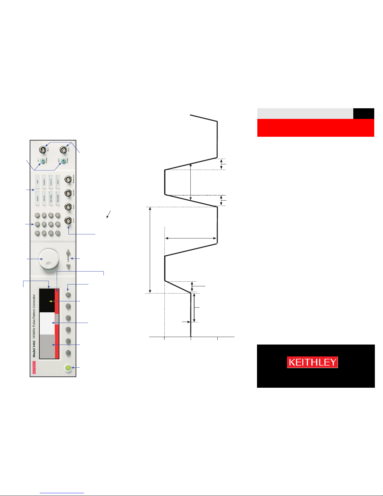
Keithley Instruments 3402 Front panel
NOTE: Front panel controls and connectors for the Keithley 3401
single-channel pulse/pattern generator are similar except
there is only one channel.
Pulse Parameters Example
Series 3400 Pulse Pattern Generator
Quick Start Guide
3400S-903-01 Rev B. / January 2007
On/Off
Switch
1
2
LCD Display
Channel 1
Parameters
2a
Selected
Parameter
2c
Channel 2
Parameters
2b
5
Rotory Knob
Cursor Keys
7
6
Numeric Keypad
3
Menu
Keys
Clock, Trigger and
Strobe Connectors
(BNC)
10
8
Output Enable
Pulse/Pattern
Output
Connectors
(BNC)
9
Soft Keys
4
Soft Key
Options
For the Model 340x-R Rear Panel
Output option, item 10 connectors
are moved to the rear panel.
2 Width
Delay
LeadE
TrailE
3.00 ns
0 ps
2.5 ns
2.5 ns
Pulse Mode
Ch 1 Width
3.04 ns
Trigger = PLL
1 Width
Delay
LeadE
TrailE
3.04 ns
0 ps
2.5 ns
2.5 ns
Freq 165.0 MHz Per 6.06 ns
Channel Freq Per Width Delay More
Ampl
(Amplitude)
1Vpp
Width
+500mV
-500mV
Per
(Period)
LeadE
(Leading Edge)
Trigger
Delay
0V
HiLvl
(High
Level)
LoLvl
(Low Level)
Offset
(Median)
Freq
(Frequency)
LeadE
(Leading Edge)
TrailE
(Trailing Edge)
Time Parameters
Not Drawn To Scale
A GREATER MEASURE OF CONFIDENCE
 Loading...