

Page 1

Model 3390
Arbitrary Waveform Generator
User’s Manual
3390-900-01 Rev. C / January 2009
www.keithley.com
G
A
T
E
E
A
R
A EM
R
E
O
RUS
C
F
I F
N O
EC N ED
Page 2

Page 3

WARRANTY
Keithley Instruments, Inc. warrants this product to be free from defects in material and workmanship for a period of
one (1) year from date of shipment.
Keithley Instruments, Inc. warrants the following items for 90 days from the date of shipment: probes, cables,
software, rechargeable batteries, diskettes, and documentation.
During the warranty period, Keithley Instruments will, at its option, either repair or replace any product that proves
to be defective.
To exercise this warranty, write or call your local Keithley Instruments representative, or contact
Keithley Instruments headquarters in Cleveland, Ohio. You will be given prompt assistance and return instructions.
Send the product, transportation prepaid, to the indicated service facility. Repairs will be made and the product
returned, transportation prepaid. Repaired or replaced products are warranted for the balance of the original
warranty period, or at least 90 days.
LIMITATION OF WARRANTY
This warranty does not apply to defects resulting from product modification without Keithley Instruments’ express
written consent, or misuse of any product or part. This warranty also does not apply to fuses, software,
non-rechargeable batteries, damage from battery leakage, or problems arising from normal wear or failure to follow
instructions.
THIS WARRANTY IS IN LIEU OF ALL OTHER WARRANTIES, EXPRESSED OR IMPLIED, INCLUDING ANY
IMPLIED WARRANTY OF MERCHANTABILITY OR FITNESS FOR A PARTICULAR USE. THE REMEDIES
PROVIDED HEREIN ARE BUYER’S SOLE AND EXCLUSIVE REMEDIES.
NEITHER KEITHLEY INSTRUMENTS, INC. NOR ANY OF ITS EMPLOYEES SHALL BE LIABLE FOR ANY
DIRECT, INDIRECT, SPECIAL, INCIDENTAL, OR CONSEQUENTIAL DAMAGES ARISING OUT OF THE USE
OF ITS INSTRUMENTS AND SOFTWARE, EVEN IF KEITHLEY INSTRUMENTS, INC. HAS BEEN ADVISED IN
ADVANCE OF THE POSSIBILITY OF SUCH DAMAGES. SUCH EXCLUDED DAMAGES SHALL INCLUDE, BUT
ARE NOT LIMITED TO: COST OF REMOVAL AND INSTALLATION, LOSSES SUSTAINED AS THE RESULT OF
INJURY TO ANY PERSON, OR DAMAGE TO PROPERTY.
A G R E A T E R M E A S U R E O F C O N F I D E N C E
Keithley Instruments, Inc.
Corporate Headquarters • 28775 Aurora Road • Cleveland, Ohio 44139
440-248-0400 • Fax: 440-248-6168 • 1-888-KEITHLEY (1-888-534-8453) • www.keithley.com
3/07
Page 4

This page left blank intentionally.
Page 5

Model 3390
Arbitrary Waveform Generator
User’s Manual
©2008, Keithley Instruments, Inc.
Cleveland, Ohio, USA
All rights reserved.
Any unauthorized reproduction, photocopy, or use the information herein, in whole or in part, without the prior written approval
of Keithley Instruments, Inc. is strictly prohibited.
KiWAVE™ is a trademark of Keithley Instruments, Inc. All Keithley Instruments product names are trademarks or registered
trademarks of Keithley Instruments, Inc. Other brand names are trademarks or registered trademarks of their
respective holders.
Document Number: 3390-900-01 Rev. C / January 2009
Page 6

This page left blank intentionally.
Page 7

Safety Precautions
The following safety precautions should be observed before using this product and any associated instrumentation. Although some
instruments and accessories would normally be used with non-hazardous voltages, there are situations where hazardous conditions may
be present.
This product is intended for use by qualified personnel who recognize shock hazards and are familiar with the safety precautions required
to avoid possible injury. Read and follow all installation, operation, and maintenance information carefully before using the product. Refer
to the user documentation for complete product specifications.
If the product is used in a manner not specified, the protection provided by the product warranty may be impaired.
The types of product users are:
Responsible body is the individual or group responsible for the use and maintenance of equipment, for ensuring that the equipment is
operated within its specifications and operating limits, and for ensuring that operators are adequately trained.
Operators use the product for its intended function. They must be trained in electrical safety procedures and proper use of the instrument.
They must be protected from electric shock and contact with hazardous live circuits.
Maintenance personnel perform routine procedures on the product to keep it operating properly, for example, setting the line voltage or
replacing consumable materials. Maintenance procedures are described in the user documentation. The procedures explicitly state if the
operator may perform them. Otherwise, they should be performed only by service personnel.
Service personnel are trained to work on live circuits, perform safe installations, and repair products. Only properly trained service
personnel may perform installation and service procedures.
Keithley Instruments products are designed for use with electrical signals that are rated Measurement Category I and Measurement
Category II, as described in the International Electrotechnical Commission (IEC) Standard IEC 60664. Most measurement, control, and
data I/O signals are Measurement Category I and must not be directly connected to mains voltage or to voltage sources with high transient
over-voltages. Measurement Category II connections require protection for high transient over-voltages often associated with local AC
mains connections. Assume all measurement, control, and data I/O connections are for connection to Category I sources unless otherwise
marked or described in the user documentation.
Exercise extreme caution when a shock hazard is present. Lethal voltage may be present on cable connector jacks or test fixtures. The
American National Standards Institute (ANSI) states that a shock hazard exists when voltage levels greater than 30V RMS, 42.4V peak,
or 60VDC are present. A good safety practice is to expect that hazardous voltage is present in any unknown circuit before measuring.
Operators of this product must be protected from electric shock at all times. The responsible body must ensure that operators are
prevented access and/or insulated from every connection point. In some cases, connections must be exposed to potential human contact.
Product operators in these circumstances must be trained to protect themselves from the risk of electric shock. If the circuit is capable of
operating at or above 1000V, no conductive part of the circuit may be exposed.
Do not connect switching cards directly to unlimited power circuits. They are intended to be used with impedance-limited sources. NEVER
connect switching cards directly to AC mains. When connecting sources to switching cards, install protective devices to limit f
and voltage to the card.
Before operating an instrument, ensure that the line cord is connected to a properly-grounded power receptacle. Inspect the connecting
cables, test leads, and jumpers for possible wear, cracks, or breaks before each use.
ault current
11/ 07
Page 8

When installing equipment where access to the main power cord is restricted, such as rack mounting, a separate main input power
!
disconnect device must be provided in close proximity to the equipment and within easy reach of the operator.
For maximum safety, do not touch the product, test cables, or any other instruments while power is applied to the circuit under test.
ALWAYS remove power from the entire test system and discharge any capacitors before: connecting or disconnecting cables or jumpers,
installing or removing switching cards, or making internal changes, such as installing or removing jumpers.
Do not touch any object that could provide a current path to the common side of the circuit under test or power line (earth) ground. Always
make measurements with dry hands while standing on a dry, insulated surface capable of withstanding the voltage being measured.
The instrument and accessories must be used in accordance with its specifications and operating instructions, or the safety of the
equipment may be impaired.
Do not exceed the maximum signal levels of the instruments and accessories, as defined in the specifications and operating information,
and as shown on the instrument or test fixture panels, or switching card.
When fuses are used in a product, replace with the same type and rating for continued protection against fire hazard.
Chassis connections must only be used as shield connections for measuring circuits, NOT as safety earth ground connections.
If you are using a test fixture, keep the lid closed while power is applied to the device under test. Safe operation requires the use of a lid
interlock.
If a screw is present, connect it to safety earth ground using the wire recommended in the user documentation.
The symbol on an instrument indicates that the user should refer to the operating instructions located in the user documentation.
The symbol on an instrument shows that it can source or measure 1000V or more, including the combined effect of normal and
common mode voltages. Use standard safety precautions to avoid personal contact with these voltages.
The symbol on an instrument shows that the surface may be hot. Avoid personal contact to prevent burns.
The symbol indicates a connection terminal to the equipment frame.
If this symbol is on a product, it indicates that mercury is present in the display lamp. Please note that the lamp must be properly
disposed of according to federal, state, and local laws.
The WARNING heading in the user documentation explains dangers that might result in personal injury or death. Always read the
associated information very carefully before performing the indicated procedure.
The CAUTION heading in the user documentation explains hazards that could damage the instrument. Such damage may invalidate the
warranty.
Instrumentation and accessories shall not be connected to humans.
Before performing any maintenance, disconnect the line cord and all test cables.
To maintain protection from electric shock and fire, replacement components in mains circuits - including the power transformer, test leads,
and input jacks - must be purchased from Keithley Instruments. Standard fuses with applicable national safety approvals may be used if
the rating and type are the same. Other components that are not safety-related may be purchased from other suppliers as long as they
are equivalent to the original component (note that selected parts should be purchased only through Keithley Instruments to maintain
accuracy and functionality of the product). If you are unsure about the applicability of a replacement component, call a Keithley Instruments
office for information.
To clean an instrument, use a damp cloth or mild, water-based cleaner. Clean the exterior of the instrument only. Do not apply cleaner
directly to the instrument or allow liquids to enter or spill on the instrument. Products that consist of a circuit board with no case or chassis
(e.g., a data acquisition board for installation into a computer) should never require cleaning if handled according to instructions. If the
board becomes contaminated and operation is affected, the board should be returned to the factory for proper cleaning/servicing.
Page 9

Table of Contents
Section Topic Page
1 Introduction............................................................................................. 1-1
General information .................................................................................... 1-2
Contact information .............................................................................. 1-2
Inspection............................................................................................. 1-2
Options and accessories...................................................................... 1-2
Model summary .......................................................................................... 1-2
Features ............................................................................................... 1-2
Handle adjustment...................................................................................... 1-3
Removing the handle ........................................................................... 1-3
Adjusting the handle position ............................................................... 1-4
Connect and power the instrument ............................................................. 1-5
Line power connection ......................................................................... 1-5
Ventilation................................................................................................... 1-6
2 Front Panel.............................................................................................. 2-1
Front panel description ............................................................................... 2-2
Front panel.................................................................................................. 2-3
Power key ............................................................................................ 2-3
Graph/Local key ................................................................................... 2-3
Menu operation soft keys ..................................................................... 2-3
Display ................................................................................................. 2-3
Navigation wheel, cursor keys, and numeric keypad ........................... 2-3
Output connector.................................................................................. 2-4
Sync output connector ......................................................................... 2-4
Trigger key ........................................................................................... 2-4
Output key............................................................................................ 2-4
Help menu key ..................................................................................... 2-4
Utility menu key.................................................................................... 2-4
Store/Recall menu key ......................................................................... 2-5
Modulation, Sweep, and Burst keys..................................................... 2-5
Waveform selection keys ..................................................................... 2-5
3 Rear Panel............................................................................................... 3-1
Rear panel description................................................................................ 3-2
Rear panel connections .............................................................................. 3-2
10 MHz Out and In connectors ............................................................ 3-2
Power connector .................................................................................. 3-3
GPIB, USB, and LAN ports .................................................................. 3-3
Trig In/Out, FSK / Burst connector ....................................................... 3-3
Modulation In connector....................................................................... 3-3
Digital Output/low voltage transistor-transistor logic (LVTTL) port ....... 3-3
4 Setup Basics........................................................................................... 4-1
Editing parameter values and settings........................................................ 4-2
Numerical entry .................................................................................... 4-2
Alphabetical entry................................................................................. 4-2
General functions and settings ................................................................... 4-2
Selecting output function...................................................................... 4-2
Setting frequency or period .................................................................. 4-3
Setting amplitude ................................................................................. 4-3
Setting DC offset voltage...................................................................... 4-4
Page 10

Table of Contents Model 3390 Arbitrary Waveform Generator User’s Manual
Setting pulse high and low levels ......................................................... 4-5
Setting waveform polarity ..................................................................... 4-5
Setting output termination..................................................................... 4-5
Setting voltage auto ranging ................................................................. 4-6
Front panel connections.............................................................................. 4-7
Controlling the output signal ................................................................. 4-7
Controlling the sync signal.................................................................... 4-7
Default settings ........................................................................................... 4-8
Restoring factory default settings ......................................................... 4-9
5 Waveform Output Operations............................................................. 5-1
Introduction ................................................................................................. 5-2
Output operations........................................................................................ 5-2
Sine waveform...................................................................................... 5-2
Square waveform ................................................................................. 5-3
Ramp waveform ................................................................................... 5-4
Noise waveform.................................................................................... 5-5
Pulse waveform .................................................................................... 5-5
Arbitrary waveform ............................................................................... 5-7
Amplitude modulation ........................................................................... 5-9
Frequency modulation ........................................................................ 5-10
Phase modulation ............................................................................... 5-12
Frequency-shift keying modulation..................................................... 5-14
Pulse width modulation waveform ...................................................... 5-15
Frequency sweep ............................................................................... 5-17
Burst operation ................................................................................... 5-20
Pattern output operation ..................................................................... 5-24
6 System Operations................................................................................ 6-1
Introduction ................................................................................................. 6-2
Instrument system operations ..................................................................... 6-2
Storing the instrument state .................................................................. 6-2
Controlling the display .......................................................................... 6-4
Controlling the error beep..................................................................... 6-4
Controlling the system sound ............................................................... 6-4
Performing self-test ............................................................................. 6-5
7 Remote Programming........................................................................... 7-1
Remote interface operation ......................................................................... 7-2
KiWAVE™ software installation ............................................................ 7-2
USB interface ....................................................................................... 7-2
IEEE-488 (GPIB) interface ................................................................... 7-3
LAN interface ........................................................................................ 7-3
LXI™ function ....................................................................................... 7-5
Remote interface commands ...................................................................... 7-8
A SCPI Command Reference................................................................. A-1
SCPI commands ........................................................................................ A-2
Command format ....................................................................................... A-2
Command separators................................................................................. A-2
Using the MIN and MAX parameters ......................................................... A-3
Querying parameter settings...................................................................... A-3
Command terminators................................................................................ A-3
IEEE-488.2 common commands ............................................................... A-3
Parameter types......................................................................................... A-4
Output data formats ................................................................................... A-5
SCPI status model ..................................................................................... A-6
Status register sets .............................................................................. A-7
Status Byte Register and service request............................................ A-7
Questionable Data Register................................................................. A-8
Standard Event Register...................................................................... A-8
SCPI command summary .......................................................................... A-9
ii 3390-900-01 Rev. C / January 2009
Page 11

Model 3390 Arbitrary Waveform Generator User’s Manual Table of Contents
B Error Messages...................................................................................... B-1
Introduction ................................................................................................ B-2
Error message definitions .......................................................................... B-2
C Application Programs.......................................................................... C-1
About application programs ....................................................................... C-2
Application examples ................................................................................. C-2
Index .................................................................................................................... Index-1
3390-900-01 Rev. C / January 2009 iii
Page 12

Table of Contents Model 3390 Arbitrary Waveform Generator User’s Manual
This page left blank intentionally.
iv 3390-900-01 Rev. C / January 2009
Page 13

List of Figures
Section Figure Title Page
1 Figure 1-1 Moving the handle to an upright position ....................................... 1-3
1 Figure 1-2 Removing the handle from the instrument..................................... 1-4
1 Figure 1-3 Default handle position for packing................................................ 1-4
1 Figure 1-4 Operation handle position.............................................................. 1-5
1 Figure 1-5 Carrying handle position ................................................................ 1-5
2 Figure 2-1 Model 3390 front panel .................................................................. 2-2
2 Figure 2-2 Graph mode ................................................................................... 2-3
2 Figure 2-3 Default local mode ......................................................................... 2-3
3 Figure 3-1 Model 3390 rear panel................................................................... 3-2
4 Figure 4-1 Setting instrument frequency ......................................................... 4-3
4 Figure 4-2 Setting instrument period............................................................... 4-3
4 Figure 4-3 Setting instrument amplitude ......................................................... 4-4
4 Figure 4-4 Setting DC offset voltage ............................................................... 4-4
4 Figure 4-5 Setting waveform polarity .............................................................. 4-5
4 Figure 4-6 Setting voltage auto ranging to Auto.............................................. 4-6
4 Figure 4-7 Setting voltage auto ranging to Hold.............................................. 4-6
4 Figure 4-8 Setting the instrument to default .................................................... 4-9
4 Figure 4-9 Accept default setting change........................................................ 4-9
5 Figure 5-1 Setting the high-voltage level......................................................... 5-2
5 Figure 5-2 Setting the low-voltage level .......................................................... 5-2
5 Figure 5-3 Setting up a sine waveform ........................................................... 5-3
5 Figure 5-4 Setting up a square waveform ....................................................... 5-4
5 Figure 5-5 Setting up a ramp waveform .......................................................... 5-4
5 Figure 5-6 Setting up a noise waveform ......................................................... 5-5
5 Figure 5-7 Setting up a pulse waveform ......................................................... 5-7
5 Figure 5-8 Press the soft key under Select Wform ......................................... 5-8
5 Figure 5-9 Press the soft key under Built In .................................................... 5-8
5 Figure 5-10 Press the soft key corresponding with the desired waveform........ 5-8
5 Figure 5-11 Press the soft keys corresponding with AM................................. 5-10
5 Figure 5-12 Press the soft keys corresponding with FM................................. 5-12
5 Figure 5-13 Press the soft keys corresponding with PM................................. 5-13
5 Figure 5-14 Press the soft keys corresponding with FSK ............................... 5-15
5 Figure 5-15 Press the soft keys corresponding with PWM ............................. 5-16
5 Figure 5-16 Press the soft keys corresponding with frequency sweep........... 5-19
5 Figure 5-17 Press the soft keys corresponding with trigger setting ................ 5-19
5 Figure 5-18 Press the soft keys corresponding with trigger selection
(internal triggering shown) .................................................................... 5-22
5 Figure 5-19 Press the soft keys corresponding with trigger slope .................. 5-23
5 Figure 5-20 Press the soft keys corresponding with gated burst .................... 5-23
5 Figure 5-21 Setting frequency or period for pattern output ............................. 5-24
5 Figure 5-22 Setting start address for pattern output ....................................... 5-24
5 Figure 5-23 Setting end address for pattern output ........................................ 5-24
5 Figure 5-24 Setting repeat on or off for pattern output .................................... 5-25
5 Figure 5-25 Selecting waveform for pattern output......................................... 5-25
Page 14

List of Figures Model 3390 Arbitrary Waveform Generator User’s Manual
5 Figure 5-26 Selecting slope for pattern output ................................................ 5-25
5 Figure 5-27 Pattern generator cable................................................................ 5-26
5 Figure 5-28 Socket pin out structure ............................................................... 5-26
5 Figure 5-29 Connector pin out structure.......................................................... 5-26
6 Figure 6-1 Press the Store / Recall key to access the instrument state menu 6-2
6 Figure 6-2 Enter the name for the selected memory location.......................... 6-2
6 Figure 6-3 Select the desired memory location for recall ................................ 6-3
6 Figure 6-4 Select the desired memory location for deletion ............................ 6-3
7 Figure 7-1 LXI browser Web Control interface ................................................ 7-7
7 Figure 7-2 LXI browser Web Control Help page.............................................. 7-8
A Figure A-1 Model 3390 status model .............................................................. A-6
2 3390-900-01 Rev. C / January 2009
Page 15

List of Tables
Section Table Title Page
2 Table 2-1 Item descriptions............................................................................ 2-2
3 Table 3-1 Rear panel item descriptions ......................................................... 3-2
4 Table 4-1 Waveform function frequency ranges ............................................ 4-3
4 Table 4-2 Sync signal and function relationships........................................... 4-7
4 Table 4-3 Factory default settings.................................................................. 4-8
5 Table 5-1 Parameters for each burst mode ................................................. 5-20
A Table A-1 IEEE-488.2 Common commands .................................................. A-3
A Table A-2 Output data formats ....................................................................... A-5
A Table A-3 Status Byte register........................................................................ A-7
A Table A-4 Questionable Data register ............................................................ A-8
A Table A-5 Standard Event register ................................................................. A-8
A Table A-6 SCPI command summary.............................................................. A-9
B Table B-1 Command errors............................................................................ B-2
B Table B-2 Execution errors............................................................................. B-3
B Table B-3 Device-dependent errors ............................................................... B-8
B Table B-4 Query errors................................................................................... B-8
B Table B-5 Instrument errors ........................................................................... B-9
B Table B-6 Self-test errors ............................................................................... B-9
B Table B-7 Arbitrary waveform errors .............................................................. B-9
CTable C-1APPLy example commands.......................................................... C-2
C Table C-2 SRQ example commands.............................................................. C-2
C Table C-3 Amplitude modulation example commands ................................... C-2
C Table C-4 Linear sweep example commands ................................................ C-3
C Table C-5 Pulse waveform example commands ............................................ C-3
C Table C-6 Pulse width modulation example commands................................. C-3
Page 16

List of Tables Model 3390 Arbitrary Waveform Generator User’s Manual
This page left blank intentionally.
2 3390-900-01 Rev. C / January 2009
Page 17

In this section:
Topic Page
General information................................................................................. 1-2
Model summary....................................................................................... 1-2
Handle adjustment .................................................................................. 1-3
Connect and power the instrument ......................................................... 1-5
Section 1
Introduction
Contact information ......................................................................... 1-2
Inspection........................................................................................ 1-2
Options and accessories................................................................. 1-2
Features.......................................................................................... 1-2
Removing the handle...................................................................... 1-3
Adjusting the handle position .......................................................... 1-4
Line power connection .................................................................... 1-5
Ventilation................................................................................................ 1-6
Page 18

Section 1: Introduction Model 3390 Arbitrary Waveform Generator User’s Manual
General information
Contact information
If you have any questions after reviewing this information, please contact your local Keithley
Instruments representative or call one of our applications engineers at 1-888-KEITHLEY
(1-888-534-8453) within the U.S. and Canada. You can also visit the Keithley Instruments website
at www.keithley.com for updated worldwide contact information.
Inspection
Your Keithley Instruments Model 3390 Arbitrary Waveform Generator was carefully inspected
electrically and mechanically before shipment. After unpacking all items from the shipping carton,
check for any obvious signs of physical damage that may have occurred during transit (there may
be a protective film over the display lens, which can be removed). Report damage to the shipping
agent immediately. Save the original packing carton for possible future shipment.
The following items are included with every instrument order:
• Arbitrary Waveform Generator with power cord
• One universal serial bus (USB) cable (USB-B-1)
• One pattern generator cable (005-003-00003)
• One Ethernet crossover cable (CA-180-3)
• Accessories as ordered
• Product Information CD-ROM containing the User's Manual and any applicable release
notes or addenda
Options and accessories
• Model KPCI-488A GPIB/IEEE-488 interface board for PCI bus
• Model KUSB-488A USB-to-GPIB interface adapter for USB
Model summary
The 50 MHz Model 3390 Arbitrary Waveform Generator gives you the operational flexibility
suitable for use in many different applications.
Features
• 50 MHz sine and 25 MHz square waveforms
• Pulse, ramp, noise, and DC waveforms
• 14-bit, 125 MSamples/second, 256K point arbitrary waveforms
• AM, FM, PM, FSK, and PWM modulation types
• Linear and logarithmic sweep and burst operations
• Built-in external time base (10 MHz +/- 500 Hz) synchronization
• 16-bit pattern out with a synchronized clock (up to 50 MHz)
• Universal serial bus (USB) and local area network (LAN) interfaces (general purpose
interface bus, GPIB is optional)
• LXI™ Class C compliant
• Save up to four waveforms in nonvolatile memory
1-2 Return to Section Topics 3390-900-01 Rev. C / January 2009
Page 19
Model 3390 Arbitrary Waveform Generator User’s Manual Section 1: Introduction
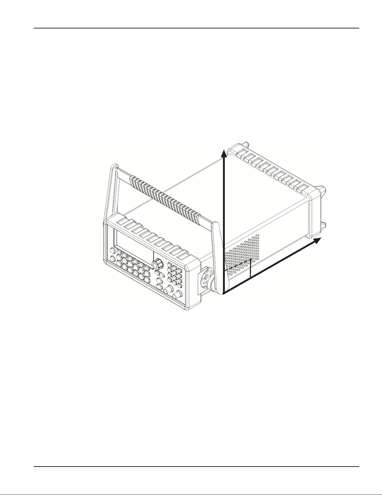
Handle adjustment
You can adjust the carrying handle to suit your needs. The following text provides detailed
information regarding handle adjustment and removal.
Removing the handle
1. Pull slightly outward on both sides of the handle and slowly rotate the handle upright to a
90º angle with the instrument (see Figure 1-1).
Figure 1-1:
Moving the handle to an upright position
3390-900-01 Rev. C / January 2009 Return to Section Topics 1-3
Page 20
Section 1: Introduction Model 3390 Arbitrary Waveform Generator User’s Manual
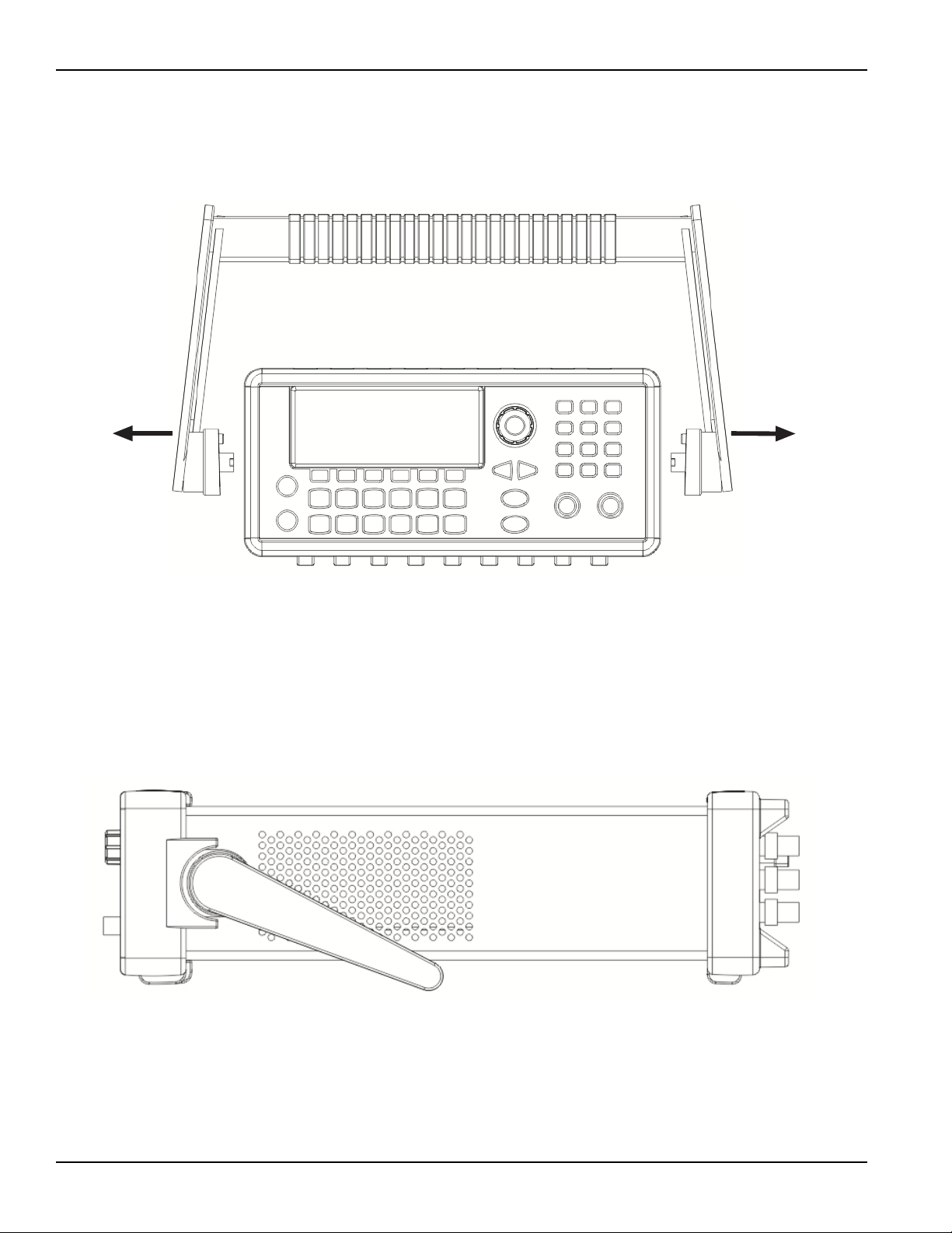
2. After the handle is turned to a 90º angle with the generator, pull the handle sides out from
the instrument (see Figure 1-2).
Figure 1-2:
Removing the handle from the instrument
Adjusting the handle position
You can adjust the handle of the Model 3390 for packing (Figure 1-3), operation (Figure 1-4), and
carrying (Figure 1-5).
Position 1: Default packing position
Figure 1-3:
Default handle position for packing
1-4 Return to Section Topics 3390-900-01 Rev. C / January 2009
Page 21
Model 3390 Arbitrary Waveform Generator User’s Manual Section 1: Introduction
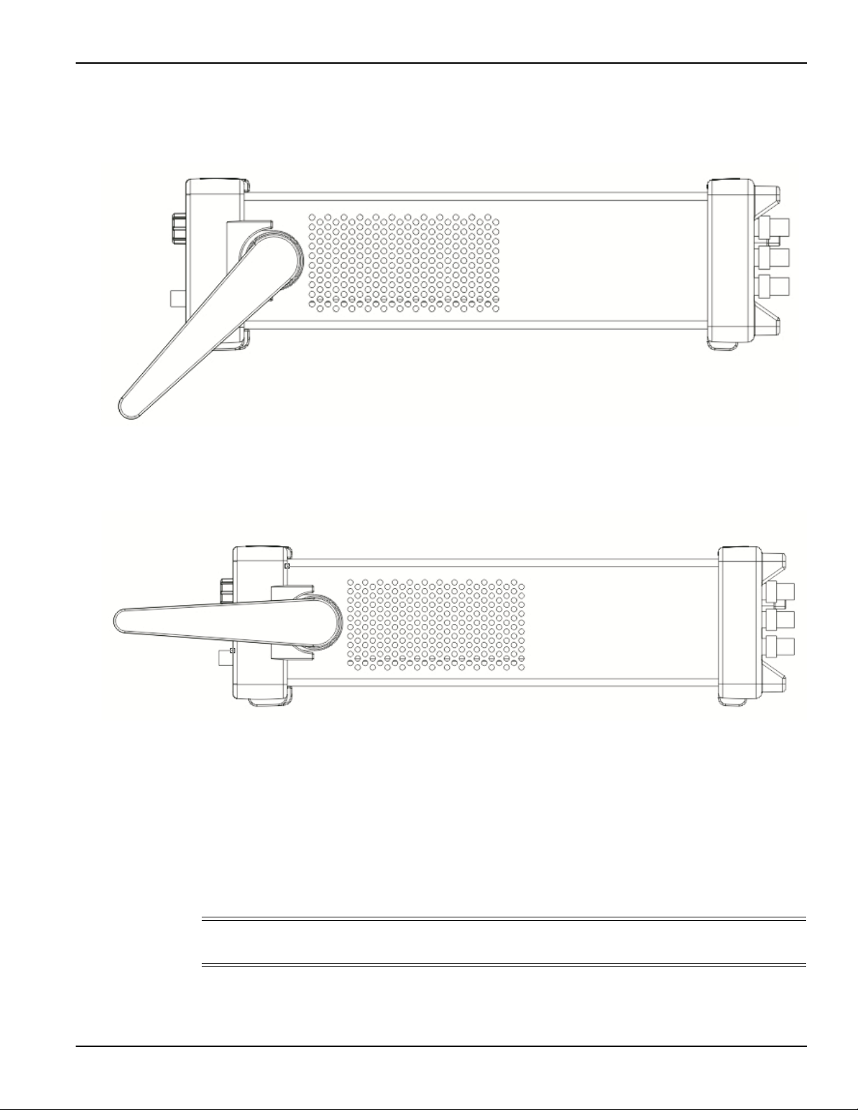
Position 2: Operation position
Figure 1-4:
Operation handle position
Position 3: Carrying position
Figure 1-5:
Carrying handle position
Connect and power the instrument
Line power connection
Follow the procedure below to connect the Model 3390 to line power and turn on the instrument.
The Model 3390 operates from a line voltage of 100 V to 240 V at a frequency of 50 Hz or 60 Hz.
Line voltage is automatically sensed; there are no switches to set. Ensure the operating voltage in
your area is compatible.
CAUTION Operating the instrument on an incorrect line voltage may cause damage to the
instrument, possibly voiding the warranty.
3390-900-01 Rev. C / January 2009 Return to Section Topics 1-5
Page 22

Section 1: Introduction Model 3390 Arbitrary Waveform Generator User’s Manual
T o connect and power your Model 3390:
1. Connect the female end of the supplied power cord to the power connector (AC receptacle)
on the rear panel. Connect the other end of the power cord to a grounded AC outlet.
2. Turn on the instrument by pressing the front-panel power key.
WARNING The power cord supplied with the Model 3390 contains a separate ground
for use with grounded outlets. When proper connections are made,
instrument chassis is connected to power line ground through th e ground
wire in the power cord. Failure to use a grounded outlet may result in
personal injury or death due to electric shock.
V entilation
The Model 3390 has a fan and cooling vents to keep it from overheating.
CAUTION Observe the following precautions to maintain proper ventilation:
Do not block the cooling vents.
Do not position any devices near the instrument that force air
(heated or unheated) into or onto the instrument's surfaces or
cooling vents. Additional airflow could compromise accuracy
performance.
Ensure adequate airflow around the instrument rear and sides for
proper cooling.
1-6 Return to Section Topics 3390-900-01 Rev. C / January 2009
Page 23

In this section:
Topic Page
Front panel description............................................................................ 2-2
Front panel .............................................................................................. 2-3
Section 2
Front Panel
Power key ....................................................................................... 2-3
Graph/Local key .............................................................................. 2-3
Menu operation soft keys ................................................................ 2-3
Display ............................................................................................ 2-3
Navigation wheel, cursor keys, and numeric keypad ...................... 2-3
Output connector ............................................................................ 2-4
Sync output connector .................................................................... 2-4
Trigger key ...................................................................................... 2-4
Output key....................................................................................... 2-4
Help menu key ................................................................................ 2-4
Utility menu key............................................................................... 2-4
Store/Recall menu key .................................................................... 2-5
Modulation, Sweep, and Burst keys................................................ 2-5
Waveform selection keys ................................................................ 2-5
Page 24
Section 2: Front Panel Model 3390 Arbitrary Waveform Generator User’s Manual
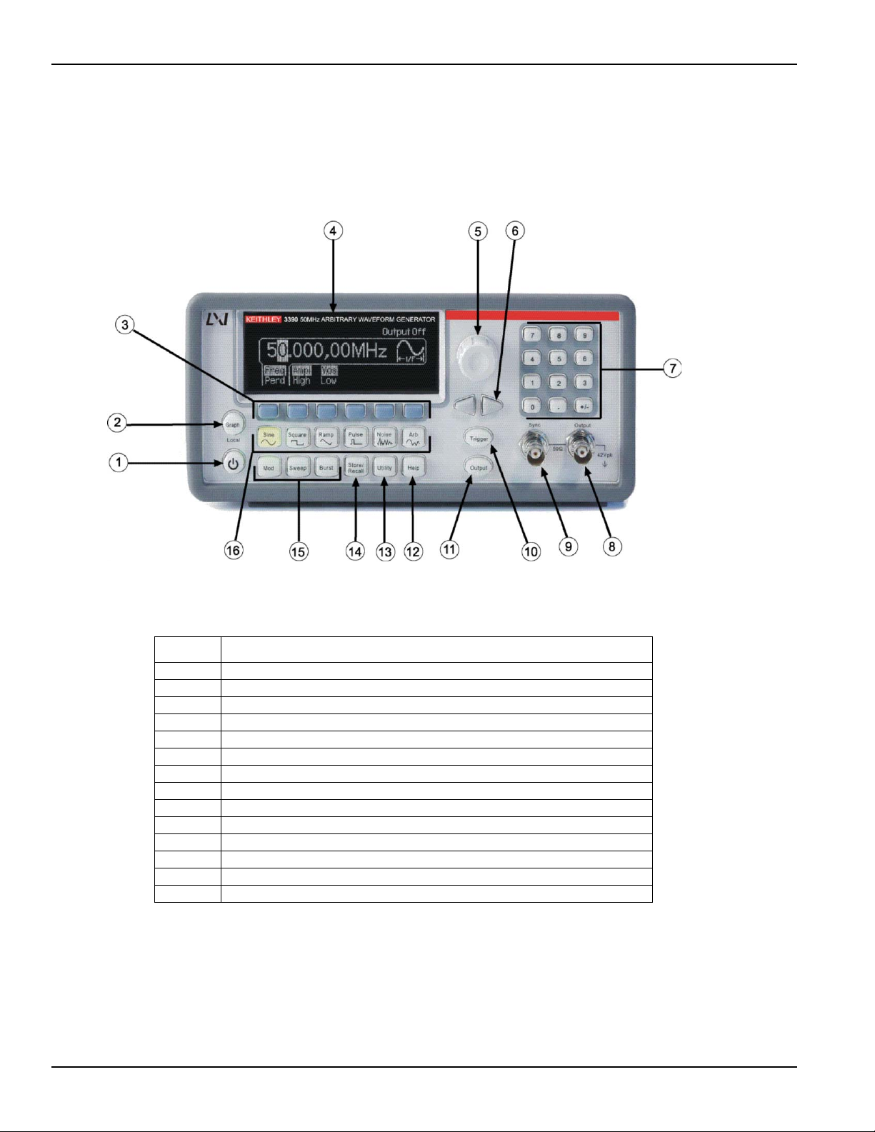
Front panel description
The Keithley Instruments Model 3390 Arbitrary Waveform Generator front panel is described in
this section (Figure 2-1).
Figure 2-1:
Model 3390 front panel
Table 2-1:
Item descriptions
Item Description
1 Power key
2 Graph/Local key
3 Menu operation soft keys
4 Display
5, 6, 7 Navigation wheel, cursor keys, and numeric keypad
8 Output connector
9 Sync output connector
10 Trigger key
11 Output key
12 Help menu key
13 Utility menu key
14 Store/Recall menu key
15 Modulation, Sweep, and Burst keys
16 Waveform selection keys
2-2 Return to Section Topics 3390-900-01 Rev. C / January 2009
Page 25
Model 3390 Arbitrary Waveform Generator User’s Manual Section 2: Front Panel
Front panel
Power key
Press this key to turn the Model 3390 on. Press it again to turn the Model 3390 off.
Graph/Local key
Pressing the Graph key enables the graph mode (Figure 2-2). You can view the waveform visually
in the graph mode and change the waveform parameters by rotating the navigation wheel and
pressing the cursor keys. The parameter values that the navigation wheel can reach in the graph
mode are limited due to resolution.
To make an exact entry, use the numeric keypad to enter the desired value. Press the Graph key
again to return to the local mode.
Figure 2-2:
Graph mode
Menu operation soft keys
Press the soft key located directly beneath the desired parameter to select that parameter. Press
the soft key again to select the display menu options. When a particular parameter is selected, the
indicator will light accordingly.
Display
The Model 3390 display provides visual information on the present active settings. The display will
update as you enter changes using the soft keys, navigation wheel, and cursor keys. Figures
displaying different modes, operations, and selections are used throughout this publication.
The following figure is an example of the display in local mode (Figure 2-3). This mode is the
default mode for the instrument display. Upon startup, the Freq, Ampl, and Vos indicators are lit.
The default waveform output of the Model 3390 is sine waveform.
Figure 2-3:
Default local mode
Navigation wheel, cursor keys, and numeric keypad
Use the numeric keypad, cursor keys, and the navigation wheel to enter numerical and
alphabetical parameters. Refer to Section 4, Editing parameter values and settings for
further information.
3390-900-01 Rev. C / January 2009 Return to Section Topics 2-3
Page 26

Section 2: Front Panel Model 3390 Arbitrary Waveform Generator User’s Manual
Output connector
This connector houses the main signal output. Refer to Section 4, Editing parameter values and
settings for details.
Sync output connector
The sync out signal is delivered at this connector. Refer to Section 4, Front panel connections
for details.
T rigger key
Press the Trigger key to manually generate an immediate trigger that is independent of the trigger
source. This is applicable to sweep, burst, and pattern out operations only.
Output key
Press the Output key to manually enable or disable the generation of waveform signals from the
front-panel output channel. The default setting is OFF. The Output key is lit when enabled.
Help menu key
The Help menu key allows access to the following information:
•View remote command error: Error messages are issued when an incorrect remote
command is sent to the instrument for output. These are stored in a queue and can be
retrieved in the first-in-first-out (FIFO) order.
•Get HELP on any key: You can view a short description of any front-panel key by pressing
and holding the key for a few seconds.
•Generate a DC voltage level: Instructions are provided for you to enable the DC-only
voltage level option.
•Generate a modulated waveform: Follow the instructions provided to produce a
modulated waveform.
•Default state resetting: Instructions enable you to return the instrument to the factory
default state.
•View a waveform in Graph Mode: This information details use of the graph mode.
•Synchronize multiple instruments: Follow the detailed instructions for connecting multiple
instruments.
•KEITHLEY Technical Support: Keithley Instruments technical support contact information
is located here.
Utility menu key
The Utility menu key allows access to the following settings and parameters:
•DC: The DC offset voltage setting can be changed from the Utility menu. The default DC
offset voltage is zero (0) volt for all functions.
•Sync: The sync out signal can be turned on and off from the Utility menu. All standard
output functions (with the exception of DC and noise) can be associated with a sync-out
signal. The signal is delivered at the Sync connector on the front panel.
•Output Setup: This key contains a number of different parameters. The output termination
setting can be changed, voltage auto ranging can be turned on and off, waveform polarity
can be specified as normal or inverted, the phase offset of the output waveform can be
adjusted, and lastly, the 10 MHz time base output can be turned on and off.
2-4 Return to Section Topics 3390-900-01 Rev. C / January 2009
Page 27

Model 3390 Arbitrary Waveform Generator User’s Manual Section 2: Front Panel
•I/O: The general purpose interface bus (GPIB) and local area network (LAN) remote
interface configurations can be set up through the Utility menu. In addition, you can view
the universal serial bus (USB) interface identification here.
•PATT Mode: You can set up pattern output through the Utility menu. Pattern output
provides five built-in patterns and up to four user-defined patterns that are stored in
nonvolatile memory.
•System: Several system parameters can be accessed through the Utility menu. The error
beeper and sound can be turned on and off, and the calibration and self-test menus can
be entered.
Store/Recall menu key
The Model 3390 has five storage locations in nonvolatile memory to store instrument state. The
stored instrument state holds all the parameters for the selected function, including the
waveform, frequency, DC offset, amplitude, duty cycle, symmetry, modulation type, and
modulation parameters.
The instrument may also be reset to its factory default settings.
Modulation, Sweep, and Burst keys
Modulation, sweep, and burst operations for the Model 3390 can be waveform-specific. The
parameters for each operation are found in Section 5, Waveform Output Operations.
Waveform selection keys
The Model 3390 has five types of standard waveforms: Sine, square, ramp, pulse, and noise
(refer to Section 5, Waveform Output Operations for detailed information). In addition, there are
five built-in arbitrary waveforms.
3390-900-01 Rev. C / January 2009 Return to Section Topics 2-5
Page 28

Section 2: Front Panel Model 3390 Arbitrary Waveform Generator User’s Manual
This page left blank intentionally.
2-6 Return to Section Topics 3390-900-01 Rev. C / January 2009
Page 29

In this section:
Topic Page
Rear panel description ............................................................................ 3-2
Rear panel connections........................................................................... 3-2
Section 3
Rear Panel
10 MHz Out and In connectors ....................................................... 3-2
Power connector ............................................................................. 3-3
GPIB, USB, and LAN ports ............................................................. 3-3
Trig In/Out, FSK / Burst connector .................................................. 3-3
Modulation In connector.................................................................. 3-3
Digital Output/low voltage transistor-transistor logic (LVTTL) port .. 3-3
Page 30
Section 3: Rear Panel Model 3390 Arbitrary Waveform Generator User’s Manual
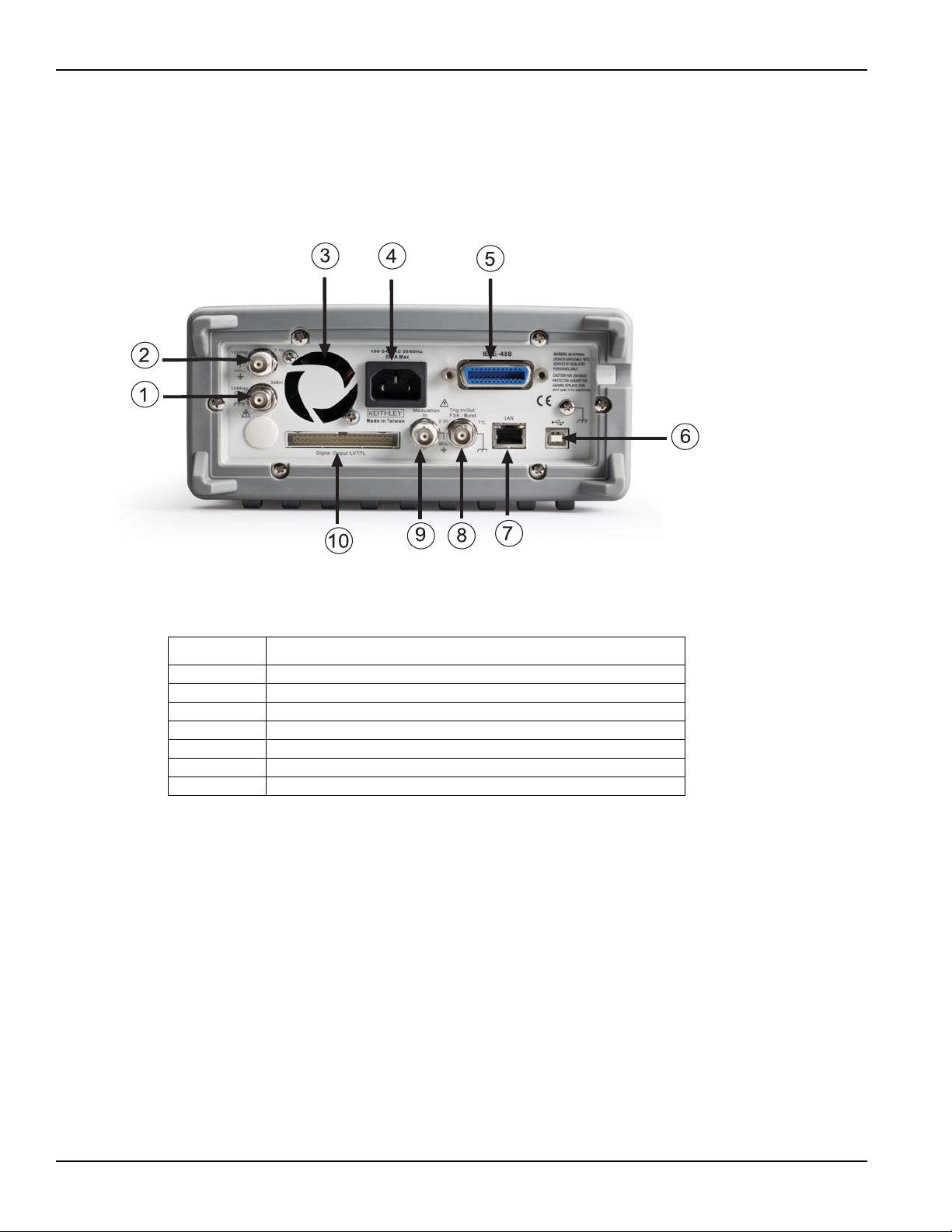
Rear panel description
The Keithley Instruments Model 3390 Arbitrary Waveform Generator rear panel is described in this
section (Figure 3-1).
Figure 3-1:
Model 3390 rear panel
Table 3-1:
Rear panel item descriptions
Item Description
1, 2 10 MHz Out and In connectors
3 Vent
4 Power connector
5, 6, 7 GPIB, USB, and LAN ports
8 Trig In/Out, FSK / Burst connector
9 Modulation In connector
10 Digital Output/low voltage transistor-transistor logic (LVTTL) port
Rear panel connections
10 MHz Out and In connectors
The 10 MHz Out connector delivers a 10 MHz single-phase signal locked to the internal instrument
clock. The 10 MHz In connector accepts an external 10 MHz clock signal. You can use these
connections to synchronize multiple instruments and control phase offset.
To set up 10 MHz Out and In from a remote interface:
Use this command to specify degrees or radians:
UNIT:ANGLe {DEGree|RADian}
Use this command to specify the phase offset of the output waveform. This value can be set in
degrees or radians as specified by the UNIT:ANGL command:
PHASe {<angle>|MINimum|MAXimum}
3-2 Return to Section Topics 3390-900-01 Rev. C / January 2009
Page 31

Model 3390 Arbitrary Waveform Generator User’s Manual Section 3: Rear Panel
Use this command to reset to a zero-phase reference point. This command does not affect the
output waveform:
PHASe:REFerence
Use this command to enable or disable the phase-lock loss error generator. This setting is stored
in volatile memory and will be reset to default (OFF) with a power off:
PHASe:UNLock:ERRor:STATe {OFF|ON}
Power connector
Connect to a grounded AC power outlet using the supplied line cord.
GPIB, USB, and LAN ports
The Model 3390 supports three remote interfaces: Universal serial bus (USB), local area network
(LAN) and general purpose interface bus (GPIB or IEEE-488). Instructions for setting up these
remote interfaces can be found in Section 7, Remote Programming.
For GPIB communication, connect to the GPIB port using an IEEE-488 cable (Keithley
Instruments Model 7007-1 or 7007-2).
T rig In/Out, FSK / Burst connector
This connector routes input and output signals.
Modulation In connector
Modulate the carrier waveform with an external waveform present at the Modulation In connector
on the rear panel (external source must be selected).
Digital Output/low volt age transistor-transistor logic (L VTTL) port
This parallel interface includes an edge-selectable clock and 16-bit data (for pattern out
operations). The 40-pin cable is used to connect the socket with your board or device.
3390-900-01 Rev. C / January 2009 Return to Section Topics 3-3
Page 32

Section 3: Rear Panel Model 3390 Arbitrary Waveform Generator User’s Manual
This page left blank intentionally.
3-4 Return to Section Topics 3390-900-01 Rev. C / January 2009
Page 33

In this section:
Topic Page
Editing parameter values and settings .................................................... 4-2
General functions and settings................................................................ 4-2
Section 4
Setup Basics
Numerical entry............................................................................... 4-2
Alphabetical entry ........................................................................... 4-2
Selecting output function................................................................. 4-2
Setting frequency or period ............................................................. 4-3
Setting amplitude ............................................................................ 4-3
Setting DC offset voltage ................................................................ 4-4
Setting pulse high and low levels .................................................... 4-5
Setting waveform polarity................................................................ 4-5
Setting output termination ............................................................... 4-5
Setting voltage auto ranging ........................................................... 4-6
Front panel connections .......................................................................... 4-7
Controlling the output signal ........................................................... 4-7
Controlling the sync signal .............................................................. 4-7
Default settings ....................................................................................... 4-8
Restoring factory default settings.................................................... 4-9
Page 34

Section 4: Setup Basics Model 3390 Arbitrary Waveform Generator User’s Manual
Editing parameter values and settings
Use the keypad, cursor keys, and navigation wheel to adjust the Model 3390 settings. The liquid
crystal display (LCD) will update as changes are made.
Numerical entry
Enter a desired value with the numeric keypad, or use the cursor keys to move the cursor on the
display and increase or decrease the digit by turning the navigation wheel.
When you use the numeric keypad for an entry, all the available units for that parameter will be
shown on the display. Press the soft key under the desired unit to finish the entry, or press Cancel
to cancel the changes. In some cases, you may need to select the soft key under DONE to finish
the entry.
Alphabetical entry
For the entry of a string of letters, turn the navigation wheel until the desired letter appears on the
display. Use the cursor keys to move the cursor to the next letter or modify the letter previously
entered. You can also use the +/- key to delete the letter previously entered.
General functions and settings
Selecting output function
Waveforms
The Model 3390 has five standard waveforms: Sine, square, ramp, pulse, and noise. To select a
desired output function, press the corresponding front-panel key, and then set related parameters
(refer to Section 5, Waveform Output Operations for detailed information). The default waveform
output is sine waveform.
There are also five built-in arbitrary waveforms. You can create a custom waveform with the
KiWAVE™ waveform editor software provided with the instrument. Refer to Section 7, KiWAVE™
software installation for software installation instructions.
Modulation, Sweep, and Burst operations
•Mod: The Model 3390 has modulation for sine, square, ramp, and arbitrary waveforms
using amplitude modulation (AM), frequency modulation (FM), phase modulation (PM), or
frequency-shift keying (FSK). You can also use pulse width modulation (PWM) for a pulse
waveform.
•Sweep: Linear and logarithmic frequency sweeping modes are included for sine, square,
ramp, and arbitrary waveforms.
•Burst: Burst waveforms can be generated with any one of the standard or arbitrary
waveforms (except DC).
To select the output function from a remote interface:
FUNCtion {SINusoid|SQUare|RAMP|PULSe|NOISe|DC|USER|PATTern}
You may also use the APPLy command to select the function, frequency, amplitude, and offset in
one command.
4-2 Return to Section Topics 3390-900-01 Rev. C / January 2009
Page 35

Model 3390 Arbitrary Waveform Generator User’s Manual Section 4: Setup Basics
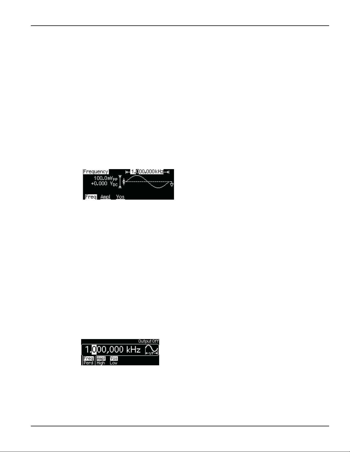
Setting frequency or period
Each waveform function has its own frequency range, but the default frequency is 1 kHz for all
functions. Refer to Table 4-1 for a list of the frequency ranges.
Table 4-1:
Waveform function frequency ranges
Function Frequency range
Sine 1
Square 1
Ramp 1
Pulse 500
Arbitrary 1
You may choose to set a frequency or period value. Press the Freq / Perd soft key to toggle
between frequency (Figure 4-1) and period (Figure 4-2).
Figure 4-1:
Setting instrument frequency
μHz to 50 MHz
μHz to 25 MHz
μHz to 200 kHz
μHz to 10 MHz
μHz to 10 MHz
Figure 4-2:
Setting instrument period
To set frequency or period:
1. Press the function key of your selection.
2. Press the soft key under Freq / Perd to select frequency or period. Ensure your selection is
highlighted.
3. Use the navigation wheel with the cursor keys, or the numeric keypad to change the value.
You can change the units by using the numeric keypad in combination with the soft keys.
To set frequency or period from a remote interface:
FREQuency {<frequency>|MINimum|MAXimum}
Setting amplitude
The default amplitude for all functions is 100 mV peak-to-peak (into 50 Ω).
To set amplitude:
1. Press the function key for your selection.
2. Press the soft key under Ampl / High. Ensure Ampl is highlighted (Figure 4-3).
3. Use the navigation wheel with the cursor keys, or the numeric keypad to change the value.
You can change the units by using the numeric keypad in combination with the soft keys.
3390-900-01 Rev. C / January 2009 Return to Section Topics 4-3
Page 36

Section 4: Setup Basics Model 3390 Arbitrary Waveform Generator User’s Manual
Figure 4-3:
Setting instrument amplitude
NOTE A momentary disruption in the output waveform may occur while changing amplitude. You
can disable the voltage auto ranging function (refer to Setting voltage auto ranging) to
prevent output disruption.
To set output amplitude from a remote interface:
VOLTage {<amplitude>|MINimum|MAXimum}
Use this command to set units:
VOLTage:UNIT {VPP|VRMS|DBM}
Setting DC offset voltage
The default DC offset voltage for all functions is zero (0) V.
To set DC offset voltage, use one of these two methods:
Method A
1. Press the function key of your selection.
2. Press the soft key under Vos / Low. Ensure Vos is highlighted (Figure 4-4).
3. Use the navigation wheel with the cursor keys, or the numeric keypad to change the value.
You can change the units by using the numeric keypad in combination with the soft keys.
Figure 4-4:
Setting DC offset voltage
Method B
NOTE Method B can be used to specify a DC voltage line out only. Also, if you use it to
set the DC offset voltage; it will hold the setting when you enter the function key
of your selection.
1. Press the Utility key.
2. Press the soft key under DC to choose DC / ON. Ensure ON is highlighted.
3. Use the navigation wheel with the cursor keys, or the numeric keypad to change the value.
You can change the units by using the numeric keypad in combination with the soft keys.
To set DC offset voltage from a remote interface:
VOLTage:OFFSet {<offset>|MINimum|MAXimum}
4-4 Return to Section Topics 3390-900-01 Rev. C / January 2009
Page 37

Model 3390 Arbitrary Waveform Generator User’s Manual Section 4: Setup Basics
Setting pulse high and low levels
You can set a high and low level versus specifying amplitude and DC offset. Parameters are
calculated as follows:
Amplitude = |High Level| + |Low Level|
Offset = (High Level + Low Level) / 2
To set pulse high and low levels:
1. Press the function key for your selection.
2. Press the soft key under Ampl / High. Ensure High is highlighted.
3. Use the navigation wheel with the cursor keys, or the numeric keypad to change the value.
You can change the units by using the numeric keypad in combination with the soft keys.
4. Press the soft key under Vos / Low. Ensure Low is highlighted.
5. Use the navigation wheel with the cursor keys, or the numeric keypad to change the value.
You can change the units by using the numeric keypad in combination with the soft keys.
To set pulse high and low levels from a remote interface:
VOLTage:HIGH {<voltage>|MINimum|MAXimum}
VOLTage:LOW {<voltage>|MINimum|MAXimum}
Setting waveform polarity
Waveform polarity can be specified as normal or inverted. When a non-zero offset is specified, the
waveform is inverted relative to the offset voltage, and the offset remains the same in the inverted
waveform. An inverted waveform does not affect the associated sync signal.
To set waveform polarity:
1. Press the Utility key, and then press the soft key under Output Setup.
2. Press the soft key under Norm / Invt to choose between normal and inverted (Figure 4-5).
Ensure your selection is highlighted.
3. Press the soft key under DONE to finish your selection.
Figure 4-5:
Setting waveform polarity
To set waveform polarity from a remote interface:
OUTPut:POLarity {NORMal|INVerted}
Setting output termination
The default output impedance to the front-panel Output connector is 50 Ω. The termination setting
is stored in nonvolatile memory and remains after a remote interface reset, or the instrument
power is turned off.
NOTE If the actual load impedance does not match the value specified, the output
amplitude and offset levels will be incorrect. Invalid results may occur.
3390-900-01 Rev. C / January 2009 Return to Section Topics 4-5
Page 38

Section 4: Setup Basics Model 3390 Arbitrary Waveform Generator User’s Manual
To set output termination:
1. Press the Utility key, and then press the soft key under Output Setup.
2. To set a load value: Press the soft key under Load / Hi-Z (Figure 4-5). Ensure Load is
highlighted. Use the navigation wheel with the cursor keys, or the numeric keypad to
change the value. You can change the units by using the numeric keypad in combination
with the soft keys.
To select high impedance: Press the Load / Hi-Z soft key again to highlight Hi-Z.
3. Press the soft key under DONE to finish your selection.
To set output termination from a remote interface:
OUTPut:LOAD {<ohms>|INFinity|MINimum|MAXimum}
Setting voltage auto ranging
Auto ranging is enabled at power up (by default) and finds optimal settings for the output amplifier
and attenuators. If auto ranging disabled, the instrument uses the current amplifier and attenuator
settings.
To enable/disable voltage auto ranging:
1. Press the Utility key, and then press the soft key under Output Setup.
2. Press the soft key under Rang to select Auto (Figure 4-6) or Hold (Figure 4- 7). Ensure your
selection is highlighted.
3. Press the soft key under DONE to finish your selection.
Figure 4-6:
Setting voltage auto ranging to Auto
Figure 4-7:
Setting voltage auto ranging to Hold
To set voltage auto ranging from a remote interface:
VOLTage:RANGe:AUTO {OFF|ON|ONCE}
4-6 Return to Section Topics 3390-900-01 Rev. C / January 2009
Page 39

Model 3390 Arbitrary Waveform Generator User’s Manual Section 4: Setup Basics
Front panel connections
The Sync and Output connectors are both located on the front panel of the Model 3390.
Controlling the output signal
Signal from the Output connector is controlled by the Output key. The output is disabled by default
at power up; this protects equipment connected to the instrument.
Press the Output key to enable the Output connector. The key is lit when output is enabled.
To enable or disable the output signal from a remote interface:
OUTPut {OFF|ON}
Controlling the sync signal
All Model 3390 output functions (except DC and noise) can be associated with a sync-out signal
(Table 4-2). The sync-out signal is delivered at the Sync connector. The output signal is at a logic
"low" level when the sync signal is disabled. The sync setting is stored in nonvolatile memory and
remains after a remote interface reset, or the instrument power is turned off.
The sync signal has three settings, ON, OFF and AUTO. The AUTO setting enables the
instrument to vary the signal with the associated function.
Table 4-2:
Sync signal and function relationships
Function Relationship
Sine, ramp, and pulse
waveforms
Square waveform Sync signal is a square waveform with the same duty cycle.
Arbitrary waveform Sync signal is a square waveform with a 50% duty cycle. The
Internally-modulated AM, FM,
PM, and PWM
Externally-modulated AM,
FM, PM, and PWM
FSK Sync signal is aligned with shifts in frequency. The signal is TTL
Triggered burst The sync signal becomes TTL "high" when the burst is triggered
Externally-gated burst The sync signal starts at TTL "high" with the external gate signal
Sync signal is a square waveform with a 50% duty cycle.
Relative to 0 volts, the signal is transistor-transistor logic (TTL)
"high" when waveform output is positive and TTL "low" when the
waveform output is negative.
signal is TTL "high" when the first waveform point is delivered.
Sync signal is a square waveform with a 50% duty cycle that is
aligned with the modulating waveform. The signal is TTL "high"
during the first half of the waveform.
Sync signal is a square waveform with a 50% duty cycle that is
aligned with the carrier waveform.
"high" during output of the hop frequency and TTL "low" during
output of the carrier frequency.
and transitions to TTL "low" at the end of the specified number of
cycles.
and transitions to TTL "low" at the end of the last cycle.
To set the sync output:
1. Press the Utility key.
2. Press the soft key under Sync. Press the soft key corresponding with your selection (ON,
OFF or AUTO).
To enable or disable the sync signal from a remote interface:
OUTPut:SYNC {OFF|ON}
3390-900-01 Rev. C / January 2009 Return to Section Topics 4-7
Page 40

Section 4: Setup Basics Model 3390 Arbitrary Waveform Generator User’s Manual
Default settings
Table 4-3 shows the factory default settings for the Model 3390. These settings will be recalled at
power up unless you set the instrument to enable a stored state.
Table 4-3:
Factory default settings
Output configuration Default setting
Function Sine waveform
Frequency 1 kHz
Amplitude/offset 100 mV peak-to-peak/0.000 V DC
Output units V peak-to-peak
Output termination 50 Ω
Auto range On
Modulation settings
Carrier 1 kHz Sine (AM, FM, PM, FSK)
1 kHz Pulse (PWM)
Modulation waveform (AM) 100 Hz Sine
Modulation waveform (PM, FM, PWM) 10 Hz Sine
AM depth 100%
FM deviation 100 Hz
PM deviation 180°
FSK hop frequency 100 Hz
FSK rate 10 Hz
PWM width deviation 10
Modulation state Off
Sweep settings
Start/stop frequency 100 Hz/1 kHz
Sweep time 1 s
Sweep mode Linear
Sweep state Off
Burst settings
Burst count 1 cycle
Burst period 10 ms
Burst start phase 0°
Burst state Off
System-based operations
Power-down recall Disabled
Display mode On
Error queue 0 errors
Output state Off
Triggering operations
Trigger source Internal (immediate)
Remote interface configuration
GPIB address 16
DHCP On
μs
4-8 Return to Section Topics 3390-900-01 Rev. C / January 2009
Page 41

Model 3390 Arbitrary Waveform Generator User’s Manual Section 4: Setup Basics
Restoring factory default settings
You can choose to reset the Model 3390 to its original factory default settings.
To restore factory default settings:
1. Press the Store / Recall key.
2. Press the soft key under Set to Def (Figure 4-8).
3. Press the soft key under YES to finish your selection (Figure 4-9).
Figure 4-8:
Setting the instrument to default
Figure 4-9:
Accept default setting change
To restore factory default settings from a remote interface:
*RST
3390-900-01 Rev. C / January 2009 Return to Section Topics 4-9
Page 42

Section 4: Setup Basics Model 3390 Arbitrary Waveform Generator User’s Manual
This page left blank intentionally.
4-10 Return to Section Topics 3390-900-01 Rev. C / January 2009
Page 43

In this section:
Topic Page
Introduction ............................................................................................. 5-2
Output operations.................................................................................... 5-2
Section 5
Waveform Output Operations
Sine waveform ................................................................................ 5-2
Square waveform ............................................................................ 5-3
Ramp waveform.............................................................................. 5-4
Noise waveform .............................................................................. 5-5
Pulse waveform .............................................................................. 5-5
Arbitrary waveform.......................................................................... 5-7
Amplitude modulation ..................................................................... 5-9
Frequency modulation .................................................................... 5-10
Phase modulation ........................................................................... 5-12
Frequency-shift keying modulation ................................................. 5-14
Pulse width modulation waveform................................................... 5-15
Frequency sweep............................................................................ 5-17
Burst operation................................................................................ 5-20
Pattern output operation ................................................................. 5-24
Page 44

Section 5: Waveform Output Operations Model 3390 Arbitrary Waveform Generator User’s Manual
Introduction
This section describes each of the Model 3390 waveform types, associated front-panel menu
options, and remote interface operations for each.
General parameters:
• Frequency and amplitude limits exist: The instrument will automatically adjust frequency or
amplitude as necessary each time a new function is selected.
• You can specify a high and low voltage level, or the amplitude and DC offset. For example,
if you set the high level to +2 volts (Figure 5-1) and the low level to -3 volts (Figure 5-2), the
resulting amplitude will be 5 V peak-to-peak, with an offset voltage of -0.5 V.
The default output unit is volts peak-to-peak (Vpp), but you can also select V RMS or dBm.
The output unit cannot be set to dBm if the output termination is set to high impedance
(Hi-Z). Output amplitude limits can be affected by the output units selected.
The unit setting is stored in volatile memory during operation. The default unit (Vpp) will be
restored after a power up or a remote interface reset.
Figure 5-1:
Setting the high-voltage level
Figure 5-2:
Setting the low-voltage level
• The output amplitude and DC offset values are constrained by the equation below:
V peak-to-peak
Where: Vmax is the maximum allowed peak voltage for the selected output termination (5 V
for a 50 Ω load, or 10 V for a high-impedance load). When the output termination setting is
changed, the output amplitude automatically adjusts.
≤
2× ( Vmax - |Voffset| )
Output operations
Sine waveform
A sine waveform is a uniform waveform with a constant frequency and amplitude.
To generate a sine waveform:
1. The default waveform output of the Model 3390 is the sine waveform. If the current output
function is not sine, press the Sine key.
5-2 Return to Section Topics 3390-900-01 Rev. C / January 2009
Page 45

Model 3390 Arbitrary Waveform Generator User’s Manual Section 5: Waveform Output Operations
2. Refer to Section 4, Setup Basics for configuring common parameters including frequency/
period, amplitude, and DC offset voltage (Figure 5-3).
3. Press the Graph key to view the waveform parameters in the graph mode.
Figure 5-3
Setting up a sine waveform
To generate a sine waveform from a remote interface:
APPLy:SINusoid [<frequency>[,<amplitude>[,<offset>]]]
or
FUNCtion {SINusoid}
FREQuency {<frequency>|MINimum|MAXimum}
VOLTage {<amplitude>|MINimum|MAXimum }
VOLTage:OFFSet {<offset>|MINimum|MAXimum }
Square waveform
A square waveform has instantaneous transitions between two voltage levels. The duty cycle of a
square waveform represents the amount of time in each cycle that the wave is at the high level
(the waveform is not inverted):
Duty Cycle = (Time Interval at High Level) / Period x 100%
The default value for duty cycle is 50%. The setting is stored in volatile memory and it will be
restored after power off or a remote interface reset. During operation, if the square waveform duty
cycle value is changed, it is stored and will be resumed when square waveform is re-selected (until
instrument power off). For square waves with frequency set above 10 MHz, the range of the duty
cycle is 40% to 60%. For lower frequency, the range is 20% to 80%. If you change frequency to a
value that is out of scope for the current duty cycle, the Model 3390 will automatically adjust the
duty cycle to the closest possible value for the new frequency. If square waveform is selected as
the modulating waveform, the duty cycle is fixed at 50%. The duty cycle setting applies to square
wave carrier waveform for AM, FM, PM, or PWM.
To generate a square waveform:
1. Press the Square key.
2. Refer to Section 4, Setup Basics for configuring common parameters including frequency/
period, amplitude, and DC offset voltage (Figure 5-4).
3. Press the soft key under Duty / Cycle. Use the navigation wheel with the cursor keys to
change the value, and then press another soft key to finish the entry and exit. Or use the
numeric keypad to enter a desired value and then press the soft key under % to finish the
entry or the soft key under Cancel to cancel the changes.
4. Press the Graph key to view the waveform parameters in the graph mode.
3390-900-01 Rev. C / January 2009 Return to Section Topics 5-3
Page 46

Section 5: Waveform Output Operations Model 3390 Arbitrary Waveform Generator User’s Manual
Figure 5-4:
Setting up a square waveform
To generate a square waveform from a remote interface:
APPLy:SQUare [<frequency>[,<amplitude>[,<offset>]]]
or
FUNCtion {SQUare}
FREQuency {<frequency>|MINimum|MAXimum}
VOLTage {<amplitude>|MINimum|MAXimum }
VOLTage:OFFSet {<offset>|MINimum|MAXimum }
FUNCtion:SQUare:DCYCle {<percent>|MINimum|MAXimum }
Ramp waveform
A ramp waveform is a triangle waveform with adjustable symmetry. Symmetry represents the
percentage of time in a cycle when the ramp waveform is rising (waveform polarity is not inverted).
The default symmetry is 100%.The symmetry value is stored in volatile memory and it will be
restored after power-off or a remote interface reset. During operation, if the output function is
changed from ramp waveform, the symmetry is stored in memory and will be resumed when ramp
waveform is re-selected (until instrument power off). The symmetry setting is not applicable when
ramp waveform is used as the modulating waveform for AM, FM, PM, or PWM.
To generate a ramp waveform:
1. Press the Ramp key.
2. Refer to Section 4, Setup Basics for configuring common parameters including frequency/
period, amplitude, and DC offset voltage (Figure 5-5).
3. Press the soft key under Symmetry. Use the navigation wheel with the cursor keys to
change the value, and then press another soft key to finish the entry and exit. Or use the
numeric keypad to enter a desired value and then press the soft key under % to finish the
entry or the soft key under Cancel to cancel the changes.
4. Press the Graph key to view the waveform parameters in the graph mode.
Figure 5-5:
Setting up a ramp waveform
To generate a ramp waveform from a remote interface:
APPLy:RAMP [<frequency>[,<amplitude>[,<offset>]]]
(The command generates a ramp waveform with 100% symmetry.)
or
FUNCtion {RAMP}
FREQuency {<frequency>|MINimum|MAXimum}
VOLTage {<amplitude>|MINimum|MAXimum }
5-4 Return to Section Topics 3390-900-01 Rev. C / January 2009
Page 47

Model 3390 Arbitrary Waveform Generator User’s Manual Section 5: Waveform Output Operations
VOLTage:OFFSet {<offset>|MINimum|MAXimum }
FUNCtion:RAMP:SYMMetry {<percent>|MINimum|MAXimum}
Noise waveform
A Gaussian noise waveform with a 20 MHz bandwidth can be generated.
To generate a noise waveform:
1. Press the Noise key.
2. Refer to Section 4, Setup Basics for configuring common parameters including amplitude
and DC offset voltage (Figure 5-6).
3. Press the Graph key to view the waveform parameters in the graph mode.
Figure 5-6:
Setting up a noise waveform
To generate a noise waveform from a remote interface:
APPLy:NOISe [<frequency|DEF>[,<amplitude>[,<offset>]]]
FUNCtion {NOISe}
VOLTage {<amplitude>|MINimum|MAXimum }
VOLTage:OFFSet {<offset>|MINimum|MAXimum }
NOTE In the APPL:NOIS command, the frequency parameter has no effect, but you
Pulse waveform
A pulse waveform has a pulse period, a pulse width or pulse duty cycle, an ascending edge, and a
descending edge.
Pulse period / frequency
The default pulse period is 1 ms (or 1 kHz in frequency), and the allowable value ranges from 100
ns to 2000 s (or 10 MHz down to 0.5 mHz in frequency). Pulse period constrains the other
parameters according to the following equation:
Pulse Period
NOTE The waveform generator adjusts the other parameters when necessary to accommodate
the given pulse period.
still must specify a value or DEFault for it.
≥
Pulse Width + 1.6 x Edge Time
Pulse width
The pulse width represents the time from the 50% point of the ascending edge to the 50% point of
the following descending edge. The default pulse width is 100 μs, and the possible value ranges
from 20 ns to 2000 s. The actual allowable range is determined as follows:
1.6 x Edge Time
Wmin
≤
Pulse Width ≤ Pulse Period - Wmin
3390-900-01 Rev. C / January 2009 Return to Section Topics 5-5
≤
Pulse Width ≤ Pulse Period - 1.6 x Edge Time
Page 48

Section 5: Waveform Output Operations Model 3390 Arbitrary Waveform Generator User’s Manual
Where: Wmin is the minimum allowable value determined by the following conditions on pulse
period:
Wmin = 20 ns, if pulse period is
200 ns, if 10 s < pulse period
2 µs, if 100 s < pulse period
20 µs, if 1000 s < pulse period
≤ 10 s
≤ 100 s
≤ 1000 s
Pulse duty cycle
Specifying pulse duty cycle is another way to define a pulse waveform (versus specifying pulse
width). Pulse duty cycle is defined as follows:
Duty Cycle = Pulse Width / Pulse Period x 100%
If the specified pulse duty cycle conflicts with the specified pulse width, or pulse width conflicts with
the duty cycle, the most recently specified parameter will be accepted. The default duty cycle is
10%, and the acceptable range is from 0% to 100% with the following constraints:
DutyCycle
DutyCycle
Where: Wmin is the minimum allowable value for pulse width as defined under the
Pulse width topic.
≥
Wmin / PulsePeriod x 100%
≤
(1.0 - Wmin / PulsePeriod) x 100%
Edge time
The edge time represents the time from the 10% point to the 90% point of an ascending or
descending edge. The default edge time is 5 ns, and the possible value ranges from 5 ns
to 100 ns, with the following constraint on the maximum allowable value:
EdgeTime
To generate a pulse waveform:
1. Press the Pulse key.
2. Refer to Section 4, Setup Basics for configuring common parameters including frequency/
3. Press the soft key under Width / Duty to select between setting pulse width or duty cycle.
NOTE You can choose to hold pulse width or duty cycle constant during changes in
4. Press the soft key under Edge / Time and use the navigation wheel with cursor keys to
5. Press the Graph key to view the waveform parameters in the graph mode.
≤
0.625 x PulseWidth
period, amplitude, and DC offset voltage (Figure 5-7).
Use the navigation wheel with the cursor keys to change the value, and then press another
soft key to finish the entry and exit. Or use the numeric keypad to enter a desired value and
then press a unit soft key, or press %, to finish the entry. Press the soft key under Cancel to
cancel the changes.
frequency. Press the soft key to highlight your selection (Width or Duty), then
enter your frequency value.
change the value, and then press another soft key to finish the entry and exit. Or use the
numeric keypad to enter a new value and then press the soft key under nsec to finish the
entry. Press the soft key under Cancel to cancel the changes.
5-6 Return to Section Topics 3390-900-01 Rev. C / January 2009
Page 49

Model 3390 Arbitrary Waveform Generator User’s Manual Section 5: Waveform Output Operations
Figure 5-7:
Setting up a pulse waveform
To generate a pulse waveform from a remote interface:
APPLy:PULSe [<frequency>[,<amplitude>[,<offset>] ]]
Or
FUNCtion {PULSe}
FREQuency {<frequency>|MINimum|MAXimum }
VOLTage {<amplitude>|MINimum|MAXimum }
VOLTage:OFFSet {<offset>|MINimum|MAXimum }
PULSe:PERiod {<seconds>|MINimum|MAXimum}
FUNCtion:PULSe:WIDTh {<seconds>|MINimum|MAXimum }
FUNCtion:PULSe:DCYCle {<percent>|MINimum|MAXimum }
FUNCtion:PULSe:TRANsition {<seconds>|MINimum|MAXimum }
Arbitrary waveform
The Model 3390 has five built-in arbitrary waveforms including, exponential-rise, exponential-fall,
negative-ramp, sinc, and cardiac. The default arbitrary waveform is an exponential-rise waveform.
In addition, up to four user-defined arbitrary waveforms can be stored in nonvolatile memory. For
each user-defined waveform, you may create up to 262,144 (256 K) points from the remote
interface. You can use the KiWAVE™ waveform editor software to create waveforms, or import the
waveforms captured previously from an oscilloscope. Refer to Section 7, KiWAVE™ software
installation for software installation instructions.
If you choose an arbitrary waveform as the modulating waveform for AM, FM, PM, or PWM, the
waveform is automatically limited to 4 K points and extra points will be removed by decimation.
NOTE If the data points do not span the full range of the output digital-to-analog
IEEE-488.2 binary block format
Following is an example of binary block format:
# 5 32768
This data begins with a number symbol (#) and is followed by a single digit that represents the
number of characters in the length. The third number represents the number of bytes (32,768
bytes = 16,384 points).
converter (DAC), the maximum amplitude will be limited.
A waveform data point is represented as a 16-bit integer sent in two bytes. The total number of
bytes is always an even number that is twice the number of data points in the waveform.
Use the FORM:BORD command to select the byte order for binary block transfers. The default
command is FORM:BORD NORM, in which the most-significant byte (MSB) of each data point is
sent first. If you specify FORM:BORD SWAP, the least-significant byte (LSB) of each data point is
sent first. The DATA:DAC command overwrites the waveform in volatile memory without
generating an error.
3390-900-01 Rev. C / January 2009 Return to Section Topics 5-7
Page 50

Section 5: Waveform Output Operations Model 3390 Arbitrary Waveform Generator User’s Manual
The following commands are point specific:
•DATA:DAC VOLATILE, {<binary block>|<value>, <value>, …}
Enter this command to download binary or decimal integer values from -8191 to +8191 into
volatile memory. The values -8191 and +8191 correspond to the peak values of the
waveform with the offset set at zero volts.
You can download from 1 to 65,536 (64K) points per waveform in IEEE-488.2 binary block
format, or as a list of values. The range of values corresponds to the values available using
internal 14-bit DAC codes.
•DATA VOLATILE, <value>, <value>, …
Enter this command to download floating-point values from -1 to +1 into volatile memory.
The values -1 and +1 correspond to the peak values of the waveform with the offset set at
zero volts. You can download from 1 to 65,536 points per waveform.
NOTE If the data points do not span the full range of the output digital-to-analog
converter (DAC), the maximum amplitude will be limited. Also, the Model 3390
expands the number of points to fill the waveform memory; less than 16,384
(16K) points will automatically generate a waveform with 16,384 points. More
than 16,384 points will automatically generate a waveform with 65,536 points.
To generate a built-in arbitrary waveform:
1. Press the Arb key.
2. Press the soft key under Select Wform (Figure 5-8), and then the soft key under Built In
(Figure 5-9).
Figure 5-8:
Press the soft key under Select Wform
Figure 5-9:
Press the soft key under Built In
3. Choose the desired waveform from the five built-in choices by pressing the corresponding
soft key (Figure 5-10). The instrument will automatically update to the chosen waveform.
Figure 5-10:
Press the soft key corresponding with the desired waveform
4. Refer to Section 4, Setup Basics for configuring common parameters including frequency/
period, amplitude, and DC offset voltage.
5. Press the Graph key to view the waveform parameters in the graph mode.
5-8 Return to Section Topics 3390-900-01 Rev. C / January 2009
Page 51

Model 3390 Arbitrary Waveform Generator User’s Manual Section 5: Waveform Output Operations
To generate an arbitrary waveform from a remote interface:
FUNCtion USER {EXP_RISE | EXP_FALL | NEG_RAMP | SINC | CARDIAC}
DATA:DAC VOLATILE, {<binary block>|<value>, <value>, …}
DATA VOLATILE, <value>, <value>, …
FORMat:BORDer {NORMal|SWAPped}
DATA:COPY <destination arb name> [,VOLATILE]
Amplitude modulation
Amplitude modulation allows the amplitude of the carrier waveform to vary with the modulating
waveform. Only one type of modulation can be active at one time; if amplitude modulation is
enabled, the previously selected modulation is automatically disabled. In addition, when amplitude
modulation is enabled, sweep mode and burst mode are disabled.
Carrier waveform
The default carrier waveform is sine. You can also choose square, ramp, and arbitrary waveforms.
The default carrier frequency is 1 kHz for all waveforms. Each carrier waveform has its own
acceptable range of frequencies. Refer to Table 4-1, Waveform function frequency ranges for
details.
Modulating waveform
The Model 3390 accepts either an internal or external modulating source.
The default source is internal with a default frequency of 100 Hz (the acceptable range is 2 mHz to
20 kHz). The default internal modulating waveform is a sine waveform, but you can also select any
of the following:
• Square waveform with 50% duty cycle
• URamp (up or positive ramp with 100% symmetry)
• DRamp (down or negative ramp with 0% symmetry)
• Triangle waveform (ramp with 50% symmetry)
• Noise waveform
• Arbitrary waveform (limited to 4 K points with automatic decimation)
Select the external modulating source to modulate the carrier waveform with an external signal
present at the Modulation In connector on the rear panel.
Modulation depth
The modulation depth controls the magnitude of the amplitude variation of the modulation output.
It is defined in the following formula:
Modulation Depth = (Max Amplitude - Min Amplitude) / Amplitude x 100%
Where: Amplitude is the specified amplitude of the carrier waveform; Max Amplitude and Min
Amplitude are the maximum and minimum amplitudes of the resulting modulation waveform.
When Modulation Depth is 0%, the amplitude of the modulation waveform stays at half of the
specified amplitude of the carrier waveform. As a result, Min Amplitude may be negative when
Modulation Depth is larger than 100%. The default Modulation Depth is 100% and the allowable
range is from 0% to 120%.
Choosing the external source means the modulation is controlled by the specified modulation
depth and the ±5 V signal levels of the external waveform. When the external waveform is at +5 V,
3390-900-01 Rev. C / January 2009 Return to Section Topics 5-9
Page 52

Section 5: Waveform Output Operations Model 3390 Arbitrary Waveform Generator User’s Manual
the amplitude of the output will reach Max Amplitude. When the external waveform is at -5 V, the
amplitude of the output will reach Min Amplitude.
The modulation output of the Model 3390 will not exceed ±5 V peak (into a 50 Ω load) even if the
modulation depth is greater than 100%.
To set up amplitude modulation:
1. Select the carrier waveform (Sine, Square, Ramp, or Arb). Follow the instructions for
setting up that specific waveform as given in this publication. Refer to Section 4, Setup
Basics for assistance.
2. Press the Mod key to access the modulation menu.
3. Press the soft key under Type; then press the soft key under AM to select amplitude
modulation (Figure 5-11). An amplitude modulation output will be generated with the set
parameters.
Figure 5-11:
Press the soft keys corresponding with AM
4. Press the soft key under Src to select between internal source (Int) and external source
(Ext) for the modulating waveform (Figure 5-11). If internal source is selected:
a) Press the soft key under Shape to select the modulating waveform. If arbitrary
waveform (Arb) is chosen, the instrument will use the currently selected arbitrary
waveform. Press the Mod key to see which arbitrary modulating waveform is
currently selected.
b) Press the soft key under AM / Freq. Use the navigation wheel with the cursor keys
to change the value, and then press another soft key to finish the entry and exit. Or
use the numeric keypad to enter a desired value and then press the soft key under
the desired units to finish the entry, or the soft key under Cancel to cancel the
changes.
5. Press the soft key under AM / Depth (Figure 5-11). Use the navigation wheel with the cursor
keys to change the value, and then press another soft key to finish the entry and exit. Or use
the numeric keypad to enter a desired value and then press the soft key under % to finish
the entry, or the soft key under Cancel to cancel the changes.
6. Press the Graph key to view the waveform parameters in the graph mode.
To set up amplitude modulation from a remote interface:
FUNCtion {SINusoid|SQUare|RAMP|USER}
FREQuency {<frequency>|MINimum|MAXimum}
VOLTage {<amplitude>|MINimum|MAXimum}
VOLTage:OFFSet {<offset>|MINimum|MAXimum}
AM:INTernal:FUNCtion {SINusoid|SQUare|RAMP|NRAMp|TRIangle|NOISe|USER}
AM:INTernal:FREQuency {<frequency>|MINimum|MAXimum}
AM:DEPTh {<depth in percent> MINimum|MAXimum }
AM:SOURce {INTernal|EXTernal}
AM:STATe {OFF|ON}
Frequency modulation
Frequency modulation allows the frequency of the carrier waveform to vary with the modulating
waveform. Only one type of modulation can be active at one time. If frequency modulation is
5-10 Return to Section Topics 3390-900-01 Rev. C / January 2009
Page 53

Model 3390 Arbitrary Waveform Generator User’s Manual Section 5: Waveform Output Operations
enabled, the previously selected modulation is automatically disabled. In addition, when frequency
modulation is enabled, sweep mode and burst mode are disabled.
Carrier waveform
The default carrier waveform is sine. You can also choose square, ramp, and arbitrary waveforms.
The default carrier frequency is 1 kHz for all waveforms. Each carrier waveform has its own
acceptable range of frequencies. Refer to Table 4-1: Waveform function frequency ranges for
details.
Modulating waveform
The Model 3390 accepts either an internal or external modulating source.
The default source is internal with a default frequency of 100 Hz (the acceptable range is 2 mHz to
20 kHz). The default internal modulating waveform is a sine waveform, but you can also select
from the following:
• Square waveform with 50% duty cycle
• URamp (up or positive ramp with 100% symmetry)
• DRamp (down or negative ramp with 0% symmetry)
• Triangle waveform (ramp with 50% symmetry)
• Noise waveform
• Arbitrary waveform (limited to 4 K points with automatic decimation)
Select the external modulating source to modulate the carrier waveform with an external signal
present at the Modulation In connector on the rear panel.
Frequency deviation
The frequency deviation represents the peak variation in the frequency of the modulation output,
based on that of the carrier waveform. The default value is 100 Hz. If a value is set greater than
allowed, the instrument will automatically adjust it to the instrument maximum. Each type of carrier
waveform has a different acceptable range:
• Sine: 1 μHz to 25.05 MHz (at carrier frequency = 25.05 MHz)
• Square: 1 μHz to 12.55 MHz (at carrier frequency = 12.55 MHz)
• Ramp: 1 μHz to 150 kHz (at carrier frequency = 150 kHz)
• Arbitrary: 1 μHz to 5.05 MHz (at carrier frequency = 5.05 MHz)
The maximum allowable value is also affected by the following:
• The frequency deviation cannot be greater than the carrier frequency.
• The sum of frequency deviation and the carrier frequency cannot be greater than the
maximum frequency of the selected carrier waveform plus 100 kHz; (50.1 MHz for sine;
25.1 MHz for square; 300 kHz for ramp; and 10.1 MHz for arbitrary waveforms).
Choosing the external source means the modulation is controlled by the specified frequency
deviation and the ±5 V signal levels of the external waveform. When the external waveform is at
+5 V, the output will reach positive maximum frequency deviation. When the external waveform is
at -5 V, the output will reach negative maximum frequency deviation.
To set up frequency modulation:
1. Select the carrier waveform (Sine, Square, Ramp, or Arb). Follow the instructions for
setting up that specific waveform as given in this publication. Refer to Section 4, Setup
Basics for assistance.
2. Press the Mod key to access the modulation menu.
3390-900-01 Rev. C / January 2009 Return to Section Topics 5-11
Page 54

Section 5: Waveform Output Operations Model 3390 Arbitrary Waveform Generator User’s Manual
3. Press the soft key under Type; then press the soft key under FM to select frequency
modulation (Figure 5-12). A frequency modulation output will be generated with the set
parameters.
Figure 5-12:
Press the soft keys corresponding with FM
4. Press the soft key under Src to select between internal source (Int) and external source
(Ext) for the modulating waveform (Figure 5-12). If internal source is selected:
a) Press the soft key under Shape to select the modulating waveform. If arbitrary
waveform (Arb) is chosen, the instrument will use the currently selected arbitrary
waveform. Press the Mod key to see which arbitrary modulating waveform is
currently selected.
b) Press the soft key under FM / Freq. Use the navigation wheel with the cursor keys
to change the value, and then press another soft key to finish the entry and exit.
Or use the numeric keypad to enter a desired value and then press the soft key
under the desired units to finish the entry, or the soft key under Cancel to cancel
the changes.
5. Press the soft key under Freq / Dev (Figure 5-12). Use the navigation wheel with the cursor
keys to change the value, and then press another soft key to finish the entry and exit. Or use
the numeric keypad to enter a desired value and then press the soft key under the desired
units to finish the entry, or the soft key under Cancel to cancel the changes.
6. Press the Graph key to view the waveform parameters in the graph mode.
To set up frequency modulation from a remote interface:
FUNCtion {SINusoid|SQUare|RAMP|USER}
FREQuency {<frequency>|MINimum|MAXimum}
VOLTage {<amplitude>|MINimum|MAXimum}
VOLTage:OFFSet {<offset>|MINimum|MAXimum}
FM:INTernal:FUNCtion {SINusoid|SQUare|RAMP|NRAMp|TRIangle|NOISe|USER}
FM:INTernal:FREQuency {<frequency>|MINimum|MAXimum}
FM:DEViation {<peak deviation in Hz>|MINimum|MAXimum }
FM:SOURce {INTernal|EXTernal}
FM:STATe {OFF|ON}
Phase modulation
Phase modulation allows the phase of the carrier waveform to vary with the modulating waveform.
Carrier waveform
The default carrier waveform is sine. You can also choose square, ramp, and arbitrary waveforms.
The default carrier frequency is 1 kHz for all waveforms. Each carrier waveform has its own
acceptable range of frequencies. Refer to Table 4-1: Waveform function frequency ranges
for details.
Modulating waveform
The Model 3390 accepts either an internal or external modulating source.
5-12 Return to Section Topics 3390-900-01 Rev. C / January 2009
Page 55

Model 3390 Arbitrary Waveform Generator User’s Manual Section 5: Waveform Output Operations
The default source is internal with a default frequency of 100 Hz (the acceptable range is 2 mHz to
20 kHz). The default internal modulating waveform is a sine waveform, but you can also select
from the following:
• Square waveform with 50% duty cycle
• URamp (up or positive ramp with 100% symmetry)
• DRamp (down or negative ramp with 0% symmetry)
• Triangle waveform (ramp with 50% symmetry)
• Noise waveform
• Arbitrary waveform (limited to 4 K points with automatic decimation)
Select the external modulating source to modulate the carrier waveform with an external signal
present at the Modulation In connector on the rear panel.
Phase deviation
The phase deviation represents the peak variation in the phase of the modulation output, based
on that of the carrier waveform. The range of the phase deviation is from 0º to 360º, and the
default is 180º.
Choosing the external source means the modulation is controlled by the specified phase deviation
and the ±5 V signal levels of the external waveform. When the external waveform is at +5 V, the
output will reach maximum positive phase deviation. When the external waveform is at -5 V, the
output will reach maximum negative phase deviation.
To set up phase modulation:
1. Select the carrier waveform (Sine, Square, Ramp, or Arb). Follow the instructions for
setting up that specific waveform as given in this publication. Refer to Section 4, Setup
Basics for assistance.
2. Press the Mod key to access the modulation menu.
3. Press the soft key under Type; then press the soft key under PM to select phase modulation
(Figure 5-13). A phase modulation output will be generated with the set parameters.
Figure 5-13:
Press the soft keys corresponding with PM
4. Press the soft key under Src to select between internal source (Int) and external source
(Ext) for the modulating waveform (Figure 5-13). If internal source is selected:
a) Press the soft key under Shape to select the modulating waveform. If arbitrary
waveform (Arb) is chosen, the instrument will use the currently selected arbitrary
waveform. Press the Mod key to see which arbitrary modulating waveform is
currently selected.
b) Press the soft key under PM / Freq. Use the navigation wheel with the cursor keys
to change the value, and then press another soft key to finish the entry and exit. Or
use the numeric keypad to enter a desired value and then press the soft key under
the desired units to finish the entry, or the soft key under Cancel to cancel the
changes.
5. Press the soft key under Phase / Dev (Figure 5-13). Use the navigation wheel with the
cursor keys to change the value, and then press another soft key to finish the entry and exit.
Or use the numeric keypad to enter a desired value and then press the soft key under deg
to finish the entry, or the soft key under Cancel to cancel the changes.
3390-900-01 Rev. C / January 2009 Return to Section Topics 5-13
Page 56

Section 5: Waveform Output Operations Model 3390 Arbitrary Waveform Generator User’s Manual
6. Press the Graph key to view the waveform parameters in the graph mode.
To set up phase modulation from a remote interface:
FUNCtion {SINusoid|SQUare|RAMP|USER}
FREQuency {<frequency>|MINimum|MAXimum}
VOLTage {<amplitude>|MINimum|MAXimum }
VOLTage:OFFSet {<offset>|MINimum|MAXimum }
PM:INTernal:FUNCtion {SINusoid|SQUare|RAMP|NRAMp|TRIangle|NOISe|USER}
PM:INTernal:FREQuency {<frequency>|MINimum|MAXimum}
PM:DEViation {<deviation in degrees>|MINimum|MAXimum }
PM:SOURce {INTernal|EXTernal}
PM:STATe {OFF|ON}
Frequency-shift keying modulation
Frequency-shift keying (FSK) modulation allows the frequency of the carrier waveform to shift
between two discrete frequencies (the carrier frequency and the hop frequency). The shifting rate
is determined by the modulating signal.
Carrier waveform
The default carrier waveform is sine. You can also choose square, ramp and arbitrary waveforms.
The default carrier frequency is 1 kHz for all waveforms. Each carrier waveform has its own
acceptable range of frequencies. Refer to Table 4-1: Waveform function frequency ranges
for details.
Modulating waveform
The Model 3390 accepts either an internal or external modulating source.
The default source is internal, and the internal modulating waveform is a square waveform with a
50% duty cycle.
Select the external modulating source to modulate the carrier waveform with an external signal
present at the Trig In/Out, FSK / Burst connector on the rear panel.
Hop frequency
The default frequency is 100 Hz. Each waveform has a different acceptable range:
• Sine: 1 μHz to 50 MHz (at carrier frequency = 1 μHz)
• Square: 1 μHz to 25 MHz (at carrier frequency = 1 μHz)
• Ramp: 1 μHz to 200 kHz (at carrier frequency = 1 μHz)
• Arbitrary: 1 μHz to 10 MHz (at carrier frequency = 1 μHz)
Choosing the external source means the modulation is controlled by the signal levels of the
external waveform. When the external waveform is at the logic "low" level, the output is at the
carrier frequency. When the external waveform is at the logic "high" level, the output is at the
hop frequency.
FSK rate
The FSK rate is the rate at which the output frequency shifts between the carrier frequency and the
hop frequency when internal source is selected. The default FSK rate is 10 Hz and the range is
from 2 mHz to 100 kHz.
5-14 Return to Section Topics 3390-900-01 Rev. C / January 2009
Page 57

Model 3390 Arbitrary Waveform Generator User’s Manual Section 5: Waveform Output Operations
To set up FSK modulation:
1. Select the carrier waveform (Sine, Square, Ramp, or Arb). Follow the instructions for
setting up that specific waveform as given in this publication. Refer to Section 4, Setup
Basics for assistance.
2. Press the Mod key to access the modulation menu.
3. Press the soft key under Type; then press the soft key under FSK to select FSK modulation
(Figure 5-14). An FSK modulation output will be generated with the set parameters.
Figure 5-14:
Press the soft keys corresponding with FSK
4. Press the soft key under Src to select between internal source (Int) and external source
(Ext) for the modulating waveform (Figure 5-14). If internal source is selected, press the soft
key under FSK / Rate. Use the navigation wheel with the cursor keys to change the value,
and then press another soft key to finish the entry and exit. Or use the numeric keypad to
enter a desired value and then press the soft key under the desired units to finish the entry,
or the soft key under Cancel to cancel the changes.
5. Press the soft key under Hop / Freq. Use the navigation wheel with the cursor keys to
change the value, and then press another soft key to finish the entry and exit. Or use the
numeric keypad to enter a desired value and then press the soft key under the desired units
to finish the entry, or the soft key under Cancel to cancel the changes.
6. Press the Graph key to view the waveform parameters in the graph mode.
To set up FSK modulation from a remote interface:
FUNCtion {SINusoid|SQUare|RAMP|USER}
FREQuency {<frequency>|MINimum|MAXimum}
VOLTage {<amplitude>|MINimum|MAXimum }
VOLTage:OFFSet {<offset>|MINimum|MAXimum }
FSKey: FREQuency {<frequency>|MINimum|MAXimum}
FSKey:INTernal:RATe {<rate in Hz>|MINimum|MAXimum }
FSKey:SOURce {INTernal|EXTernal}
FSKey:STATe {OFF|ON}
Pulse width modulation waveform
Pulse Width Modulation (PWM) allows the pulse width of the carrier waveform to vary with the
modulating waveform. The pulse width can be specified in either time units or duty cycle.
Carrier waveform
Pulse is the carrier waveform. The default period for the carrier pulse is 1 ms and the acceptable
range is 100 ns to 200 s.
Modulating waveform
The Model 3390 accepts either an internal or external modulating source.
The default source is internal with a default frequency of 10 Hz (the acceptable range is 2 mHz to
20 kHz). The default internal modulating waveform is a sine waveform, but you can also select
from the following:
3390-900-01 Rev. C / January 2009 Return to Section Topics 5-15
Page 58

Section 5: Waveform Output Operations Model 3390 Arbitrary Waveform Generator User’s Manual
• Square waveform with 50% duty cycle
• URamp (up or positive ramp with 100% symmetry)
• DRamp (down or negative ramp with 0% symmetry)
• Triangle waveform (ramp with 50% symmetry)
• Noise waveform
• Arbitrary waveform (limited to 4 K points with automatic decimation)
Select the external modulating source to modulate the carrier waveform with an external signal
present at the Modulation In connector on the rear panel.
Width deviation
The width deviation represents the peak variation in the pulse width of the modulation output
based on that of the original carrier waveform. The range of the width deviation is from 0 s to
1000 s, and the default is 10 μs.
The deviation cannot be greater than the pulse width of the carrier waveform, and has the
following constraints:
WidthDeviation
WidthDeviation
Where: Wmin is the minimum pulse width as described in the Pulse waveform section.
Choosing the external source means the modulation is controlled by the specified width deviation
and the ±5 V signal levels of the external waveform. When the external waveform is at +5 V, the
output will reach the maximum pulse width. When the external waveform is at -5 V, the output will
reach the minimum pulse width.
To set up PWM:
1. Press the Pulse soft key. Follow the instructions for setting up a pulse waveform as given in
this publication. Refer to Section 4, Setup Basics for assistance.
2. Press the Mod key to access the modulation menu.
3. Press the soft key under Src to select between internal source (Int) and external source
(Ext) for the modulating waveform (Figure 5-15). If internal source is selected:
a) Press the soft key under Shape to select the modulating waveform. If arbitrary
b) Press the soft key under PWM / Freq. Use the navigation wheel with the cursor
≤
PulseWidth - Wmin
≤
Period - (PulseWidth + Wmin)
waveform (Arb) is chosen, the instrument will use the currently selected arbitrary
waveform. Press the Mod key to see which arbitrary modulating waveform is
currently selected.
keys to change the value, and then press another soft key to finish the entry and
exit. Or use the numeric keypad to enter a desired value and then press the soft key
under the desired units to finish the entry, or the soft key under Cancel to cancel the
changes.
Figure 5-15:
Press the soft keys corresponding with PWM
4. Press the soft key under Width / Dev (Figure 5-15). Use the navigation wheel with the
cursor keys to change the value, and then press another soft key to finish the entry and exit.
Or use the numeric keypad to enter a desired value and then press the soft key under the
desired units to finish the entry, or the soft key under Cancel to cancel the changes.
5-16 Return to Section Topics 3390-900-01 Rev. C / January 2009
Page 59

Model 3390 Arbitrary Waveform Generator User’s Manual Section 5: Waveform Output Operations
5. Press the Graph key to view the waveform parameters in the graph mode.
To set up PWM from a remote interface:
VOLTage {<amplitude>|MINimum|MAXimum}
VOLTage:OFFSet {<offset>|MINimum|MAXimum}
PULSe:PERiod {<seconds>|MINimum|MAXimum}
FUNCtion:PULSe:WIDTh {<seconds>|MINimum|MAXimum}
FUNCtion:PULSe:TRANsition {<seconds>|MINimum|MAXimum}
FUNCtion:PULSe:DCYCle{<percent>|MINimum|MAXimum}
PWM:INTernal:FUNCtion {SINusoid|SQUare|RAMP|NRAMp|TRIangle|NOISe|USER}
PWM:INTernal:FREQuency {<frequency>|MINimum|MAXimum}
PWM:DEViation {<deviation in seconds>|MINimum|MAXimum}
PWM:DEViation:DCYCle {<deviation in percent>| MINimum|MAXimum}
PWM:SOURce {INTernal|EXTernal}
PWM:STATe {OFF|ON}
Frequency sweep
Frequency sweep allows a waveform to gradually step from one frequency to another at a
specified rate. The waveform can sweep up or down in frequency with logarithmic or linear
spacing. Sine, square, ramp, and arbitrary waveforms work with frequency sweep.
Sweep mode
The waveform generator has two sweep modes:
• Linear: The frequency steps with spacing calculated in a linear function.
• Logarithmic: The frequency steps with spacing calculated in a logarithmic function.
The default sweep mode is linear.
Setting frequency sweep range
You may specify start and stop frequency settings, or a center frequency and frequency span.
Start frequency and stop frequency
The waveform generator sweeps from the start frequency to the stop frequency. The instrument
will sweep down when the start frequency is greater than the stop frequency. The instrument will
sweep up when the stop frequency is greater than the start frequency.
The default start frequency is 100 Hz and the default stop frequency is 1 kHz. The allowable range
is 1 μHz to 50 MHz for sine; 1 μHz to 25 MHz for square; 1 μHz to 200 kHz for ramp; and 1 μHz to
10 MHz for arbitrary waveforms.
Center frequency and frequency span
The waveform generator sweeps from the center frequency through the distance of the
frequency span. Set a positive frequency span for sweeping up and a negative frequency span
for sweeping down.
The default center frequency is 550 Hz. The allowable range is 1 μHz to 50 MHz for sine; 1 μHz to
25 MHz for square; 1 μHz to 200 kHz for ramp; and 1 μHz to 10 MHz for arbitrary waveforms. The
default frequency span is 900 Hz. The allowable range of the frequency span is dependent on
center frequency setting and waveform selection.
Sweep time
The sweep time is the period of time (in seconds) required to sweep from the start frequency (or
center frequency) to the stop frequency (or the endpoint of the frequency span). The number of
3390-900-01 Rev. C / January 2009 Return to Section Topics 5-17
Page 60

Section 5: Waveform Output Operations Model 3390 Arbitrary Waveform Generator User’s Manual
discrete frequency points is calculated by the waveform generator according to the sweep time
specified. The default sweep time is 1 second, and the range is from 1 ms to 500 s.
Marker frequency
Marker frequency controls the sync signal that is output from the front panel Sync connector. The
default marker frequency is 500 Hz and the range of the marker frequency is dependent on stop
frequency setting or frequency span setting. The marker frequency must be less than or equal to
the maximum output frequency.
Performing a sweep with an enabled marker frequency (selected in Hz), starts the sync signal
at transistor-transistor logic (TTL) "high" at the beginning of the sweep and turns it to "low" at the
marker frequency. For sweeps with Marker Off, the Sync signal is a square waveform with a 50%
duty cycle. The Sync signal is at TTL "high" at the beginning of a sweep and turns to "low" at
the midpoint of the sweep. The frequency of the Sync signal is the reciprocal of the specified
sweep time.
Trigger source
The waveform generator outputs a single sweep when it receives a trigger signal, and it continues
delivering the same type of waveform with the start frequency before it receives the next trigger
and sends another sweep.
Trigger source can be internal, external, or manual. The default is internal.
The trigger sources perform as follows:
• Internal trigger source: The waveform generator continuously delivers sweeps at the
specified sweep time.
• External trigger source: The trigger signal is a TTL pulse with specified polarity applied to
the Trig In/Out connector on the rear panel. The trigger period cannot be less than 1 ms plus
the specified sweep time.
• Manual trigger source: The waveform generator sends out a sweep each time the Trigger
key on the front panel is pressed.
Trigger out signal
A trigger out signal is delivered at the Trig In/Out, FSK / Burst connector on the rear panel.
Trigger out signals perform as follows:
• Internal trigger source: A square waveform with 50% duty cycle is delivered at the Trig Out
connector with the sweep output.
• Manual trigger source: A pulse is delivered (with pulse width > 1 μs) at the Trig Out
connector at the beginning of each sweep.
To set up frequency sweep:
1. Select the carrier waveform (Sine, Square, Ramp, or Arb). Follow the instructions for
setting up that specific waveform as given in this publication. Refer to Section 4, Setup
Basics for assistance.
2. Press the Sweep key to access the sweep menu.
3. Press the soft key under Linear / Log to choose between linear or logarithmic mode
(Figure 5-16).
5-18 Return to Section Topics 3390-900-01 Rev. C / January 2009
Page 61

Model 3390 Arbitrary Waveform Generator User’s Manual Section 5: Waveform Output Operations
Figure 5-16:
Press the soft keys corresponding with frequency sweep
4. Select a start frequency and a stop frequency, or select a center frequency and a frequency
span:
• Start and stop frequency: Press the soft key under Start / Cn tr to specify a start
frequency (ensure Start is highlighted, Figure 5-16). Use the navigation wheel with the
cursor keys to change the value, and then press another soft key to finish the entry and
exit. Or use the numeric keypad to enter a desired value and then press the soft key
under the desired units to finish the entry, or the soft key under Cancel to cancel the
changes. Press the soft key under Stop / Span to specify a stop frequency. Follow the
same value entry procedures.
• Center frequency and frequency span: Press the soft key under St art / Cntr to specify a
center frequency (ensure Cntr is highlighted). Use the navigation wheel with the cursor
keys to change the value, and then press another soft key to finish the entry and exit. Or
use the numeric keypad to enter a desired value and then press the soft key under the
desired units to finish the entry, or the soft key under Cancel to cancel the changes.
Press the soft key under Stop / Span to specify a span frequency. Follow the same
value entry procedures.
5. Press the soft key under Sweep / Time. Use the navigation wheel with the cursor keys to
change the value, and then press another soft key to finish the entry and exit. Or use the
numeric keypad to enter a desired value and then press the soft key under the desired units
to finish the entry, or the soft key under Cancel to cancel the changes.
6. Press the soft key under Mkr to toggle between Freq and OFF. Use the navigation wheel
with the cursor keys to enter a frequency value, and then press another soft key to finish the
entry and exit. Or use the numeric keypad to enter a desired value and then press the soft
key under the desired units to finish the entry, or the soft key under Cancel to cancel the
changes.
7. Press the soft key under Trig / Setup to configure the trigger setting (Figure 5-17). Press
the soft key under Src to select among Int (internal), Ext (external), or Man (manual) for the
trigger source.
• Internal or manual source: Press the Trig / Out soft key, then select among OFF, rising-
edge, or falling edge trigger.
• External source: Press the Slope soft key, then select rising edge or falling edge trigger.
Figure 5-17:
Press the soft keys corresponding with trigger setting
8. Press the Graph key to view the waveform parameters in the graph mode.
To set up frequency sweep from a remote interface:
SWEep:SPACing {LINear|LOGarithmic}
SWEep:TIME {<seconds>|MINimum|MAXimum}
FREQuency:STARt {<frequency>|MINimum|MAXimum}
FREQuency:STOP {<frequency>|MINimum|MAXimum}
FREQuency:CENTer {<frequency>|MINimum|MAXimum}
3390-900-01 Rev. C / January 2009 Return to Section Topics 5-19
Page 62

Section 5: Waveform Output Operations Model 3390 Arbitrary Waveform Generator User’s Manual
FREQuency:SPAN {<frequency>|MINimum|MAXimum}
MARKer:FREQuency {<frequency>|MINimum|MAXimum}
MARKer {OFF|ON}
SWEep:STATe {OFF|ON}
Use this command to specify the trigger source:
TRIGger:SOURce {IMMediate|EXTernal|BUS}
Use this command to specify whether the sweep is triggered on the rising or the falling edge:
TRIGger:SLOPe {POSitive|NEGative}
Use the following commands to configure the Trig Out signal:
OUTPut:TRIGger:SLOPe {POSitive|NEGative}
OUTPut:TRIGger {OFF|ON}
Burst operation
The burst operation generates a selected waveform with a specified number of cycles (a burst).
Bursts can be triggered internally or manually. Bursts can also be triggered (or gated) externally by
a signal applied to the Trig In/Out, FSK / Burst connector on the rear panel. Sine, ramp, pulse,
square, and arbitrary waveforms can be generated in both triggered and gated burst modes. Noise
can be generated only in the gated burst mode.
Burst mode
You can select triggered or gated burst mode. Table 5-1 presents the modes and the parameters
affecting each:
•Trig gered burst mode: This mode generates a waveform with a specified number of cycles
(burst count) each time it receives a trigger. When the specified number of cycles is
generated, the instrument pauses and waits for next trigger. You can choose to trigger the
bursts using internal source, manual press of the trigger key, external signal at the Trig In/
Out, FSK / Burst connector on the rear panel, or software trigger through the remote
interface (refer to Section 7, Remote Programming for details). Triggered burst mode is the
default burst mode.
•Gated burst mode: In gated burst mode, the length of a burst is determined by the voltage
level of the external signal applied at the Trig In/Out, FSK / Burst connector on the rear
panel. When the external signal is logic true, the waveform generator outputs a continuous
waveform. When the gate signal is logic false, the output waveform remains at the same
voltage level as the starting burst phase of the selected waveform. The output stops
immediately following a noise burst when the gate signal becomes logic false.
Table 5-1:
Parameters for each burst mode
External
Burst mode Burst phase Burst count Burst period
Triggered
mode
Gated mode X X
Internal X X X
External and
Manual
XX
trigger signal
polarity
5-20 Return to Section Topics 3390-900-01 Rev. C / January 2009
Page 63

Model 3390 Arbitrary Waveform Generator User’s Manual Section 5: Waveform Output Operations
Burst phase
Burst phase defines the starting phase of a burst. The default is 0º and the range is from -360º to
+360º. You can set the burst phase in degrees from the front panel; however, degrees and radians
are both available through remote interface operation.
For sine, square, and ramp waveforms, 0º is the point at which the waveform crosses zero volt, or
the DC offset, when ascending. For arbitrary waveform, it is the first waveform point specified.
In gated burst mode, when the gate signal turns false, the waveform generator will complete the
current waveform and then stop. At this point, the output will remain at the same voltage level as
the starting burst phase.
Burst count
The burst count represents the number of cycles in each burst and is only applicable in triggered
burst mode. The default burst count is 1 cycle, and the range is from 1 to 50,000 cycles in
single-cycle increments. You can also set an infinite burst count.
NOTE If a new burst count is specified when the instrument is in gated mode, the
instrument will store the new count and implement it when a triggered mode
is selected.
Burst Period
The burst period represents the time interval between the start times of two consecutive bursts. It
is only applicable in the internally triggered burst mode. The default burst period is 10 ms and the
range is from 1 μs to 500 seconds.
Waveform frequency
The waveform frequency defines the frequency of the output waveform when trigger signal is logic
true. In triggered mode, the specified number of cycles is delivered at the waveform frequency. In
gated mode, the waveform frequency is delivered when the external gate signal is logic true.
The default waveform frequency is 1 kHz. The range is from 1 μHz to 200 kHz for ramp; 1 μHz to
25 MHz for square; 1 μHz to 10 MHz for pulse and arbitrary; and 1 μHz to 50 MHz for sine
waveforms. The minimum frequency is 2.001 mHz for internally triggered burst mode. For sine and
square waveforms, frequencies greater than 10 MHz are permitted only when an infinite burst
count is set.
T rigger source
Trigger source can be internal, external or manual.
The trigger sources perform as follows:
•Internal trigger source: Internal trigger source delivers bursts repeatedly at a rate
determined by the specified burst period, which represents the time interval between the
start times of two consecutive bursts. The burst count must be less than the product of the
burst period and the waveform frequency:
Burst Count < Burst Period x Waveform Frequency
3390-900-01 Rev. C / January 2009 Return to Section Topics 5-21
Page 64

Section 5: Waveform Output Operations Model 3390 Arbitrary Waveform Generator User’s Manual
If the burst period is set too short, the instrument automatically adjusts it to the shortest
value (up to its maximum) that can accommodate the specified burst count and waveform
frequency:
Burst period > (Burst Count ÷ Waveform Frequency) + 200 ns
•External trigger source: External trigger source delivers a burst each time a TTL pulse
with specified polarity is received at the Trig In/Out connector on the rear panel. The
instrument ignores any trigger signals received during the output of a burst. Burst period is
not applicable.
•Manual trigger source: Manual trigger source delivers a burst with each press of the
Trigger key. Burst period is not applicable.
Trigger out signal
The instrument can be set to deliver a trigger out signal at the Trig In/Out connector on the rear
panel. This signal can be enabled when the instrument is set for internal or manual triggered burst
mode, and it is synchronized with the burst output.
Trigger out signals perform as follows:
•Internal trigger source: A square waveform with 50% duty cycle is delivered at the Trig
Out connector at the beginning of the burst.
•Manual trigger source: A pulse is delivered (with pulse width > 1 µs) at the Trig Out
connector at the beginning of each sweep.
To set up burst output:
1. Select the carrier waveform (Sine, Square, Ramp, or Arb. Noise is permitted in gated burst
mode only). Follow the instructions for setting up that specific waveform as given in this
publication. Refer to Section 4, Setup Basics for assistance.
2. Press the Burst key to access the burst menu.
3. Press the soft key under N Cyc / Gated to choose between the triggered and external gated
modes (Figure 5-18). Ensure your selection is highlighted.
Figure 5-18:
Press the soft keys corresponding with trigger selection (internal triggering shown)
• Triggered burst mode:
a) Press the soft key under #Cyc / Inf to choose between finite and infinite burst
count:
• Finite burst count: Ensure that #Cyc is highlighted. Use the navigation wheel with
the cursor keys to change the value, and then press another soft key to finish the
entry and exit. Or use the numeric keypad to enter a desired value and then press
the soft key under Cyc to finish the entry, or the soft key under Cancel to cancel
the changes.
• Infinite burst count: Ensure that Inf is highlighted. The display will automatically
highlight the Start / Phase selection. Use the navigation wheel with the cursor
keys to change the value, and then press another soft key to finish the entry
and exit. Or use the numeric keypad to enter a desired value and then press the
soft key under Deg to finish the entry, or the soft key under Cancel to cancel
the changes.
5-22 Return to Section Topics 3390-900-01 Rev. C / January 2009
Page 65

Model 3390 Arbitrary Waveform Generator User’s Manual Section 5: Waveform Output Operations
b) Press the soft key under Trig / Setup to configure the trigger setting (Figure 5-18).
Press the soft key under Src to select among Int (internal), Ext (external), or Man
(manual) for the trigger source.
• Internal trigger source: Press the T rig / Out soft key, then select among OFF,
rising-edge, or falling edge trigger. Press the soft key under Burst / Perd. Use the
navigation wheel with the cursor keys to change the value, and then press
another soft key to finish the entry and exit. Or use the numeric keypad to enter a
desired value and then press the soft key under the desired units to finish the
entry, or the soft key under Cancel to cancel the changes.
• External trigger source: Press the Slope soft key, then select rising edge or falling
edge trigger (Figure 5-19).
• Manual trigger source: Press the Trig / Out soft key, then select among OFF,
rising-edge, or falling edge trigger.
c) Press the soft key under Done to finish the trigger setting.
d) Press the Graph key to view the waveform parameters in the graph mode.
Figure 5-19:
Press the soft keys corresponding with trigger slope
• External gated burst mode:
a) Press the soft key under Polar to choose between Neg and Pos for the polarity of
the external signal (Figure 5-20).
b) Press the soft key under Start / Phase. Use the navigation wheel with the cursor
keys to change the value, and then press another soft key to finish the entry and
exit. Or use the numeric keypad to enter a desired value and then press the soft key
under Deg to finish the entry, or the soft key under Cancel to cancel the changes.
Figure 5-20:
Press the soft keys corresponding with gated burst
c) Press the Graph key to view the waveform parameters in the graph mode
To set up burst operation from a remote interface:
FUNCtion {SINusoid|SQUare|RAMP|PULSe|USER}
FREQuency {<frequency>|MINimum|MAXimum}
BURSt:MODE {TRIGgered|GATed}
BURSt:GATE:POLarity { NORMal|INVerted }
BURSt:NCYCles {<#cycles>|INFinity|MINimum|MAXimum}
BURSt:INTernal:PERiod {<seconds>|MINimum|MAXimum}
BURSt:PHASe {<angle>|MINimum|MAXimum}
UNIT:ANGLe {DEGree|RADian}
TRIGger:SOURce {IMMediate|EXTernal|BUS}
TRIGger:SLOPe {POSitive|NEGative}
OUTPut:TRIGger:SLOPe {POSitive|NEGative}
OUTPut:TRIGger {OFF|ON}
BURSt:STATe {OFF|ON}
3390-900-01 Rev. C / January 2009 Return to Section Topics 5-23
Page 66

Section 5: Waveform Output Operations Model 3390 Arbitrary Waveform Generator User’s Manual
Pattern output operation
Pattern output allows you to specify a pattern of up to 256k points in 16-bit resolution. Similar to
arbitrary waveforms, pattern output provides five built-in patterns and up to four user-defined
patterns that are stored in nonvolatile memory. The built-in patterns are exponential-rise,
exponential-fall, negative-ramp, sinc, and cardiac. The default pattern output is an
exponential-rise waveform.
You can import waveforms captured with an oscilloscope, or create a custom pattern with the
KiWAVE™ waveform and pattern editor software provided with the instrument. Refer to Section 7,
KiWAVE™ software installation for software installation instructions.
To set up pattern output:
1. Press the Utility key to access the utility menu.
2. Press the soft key under PATT / Mode to access the pattern menu.
3. Press the soft key under Fclk / Perd (Figure 5-21) to choose between frequency (Fclk) and
period (Perd). Refer to Section 4, Setup Basics for assistance.
Figure 5-21:
Setting frequency or period for pattern output
4. Press the soft key under Start / Addr to specify a start point for the pattern output
(Figure 5-22). Use the navigation wheel with the cursor keys to change the value, and then
press another soft key to finish the entry and exit. Or use the numeric keypad to enter a
desired value and then press the soft key under Enter to finish the entry, or the soft key
under Cancel to cancel the changes.
Figure 5-22:
Setting start address for pattern output
5. Press the soft key under End / Addr to specify an end point for the pattern output
(Figure 5-23). Use the navigation wheel with the cursor keys to change the value, and then
press another soft key to finish the entry and exit. Or use the numeric keypad to enter a
desired value and then press the soft key under Enter to finish the entry, or the soft key
under Cancel to cancel the changes.
Figure 5-23:
Setting end address for pattern output
6. Press the soft key under Output / Setup.
a) Press the soft key under RPT. to choose between ON and OFF (Figure 5-24).
Select ON to enable the repeat output of the pattern.
b) Press the soft key under CLK to select rising edge or falling edge.
c) Press the soft key under Done to finish the selection.
5-24 Return to Section Topics 3390-900-01 Rev. C / January 2009
Page 67

Model 3390 Arbitrary Waveform Generator User’s Manual Section 5: Waveform Output Operations
Figure 5-24:
Setting repeat on or off for pattern output
7. Press the soft key under Select / Wform to access the waveform menu. Press the soft keys
to select among Built / In, Saved / Wform (saved waveform), or Delete / Saved
(Figure 5-25).
• Press the soft key under Built / In and choose from the five built-in patterns by pressing
the corresponding soft key.
• Press the soft key under Saved / Wform and choose the desired user-defined pattern
by pressing the corresponding soft key.
• Press the soft key under Delete / Saved to delete a user-defined pattern. Choose the
pattern to be deleted and press the corresponding soft key.
Figure 5-25:
Selecting waveform for pattern output
8. Press the soft key under Trig / Setup to configure the trigger setting. Press the soft key
under Src to select Ext (external) or Man (manual) for the trigger source.
• Manual source: Press the Trig Out soft key, then select among OFF, rising-edge, or
falling edge trigger.
• External source: Press the Slope soft key, then select rising edge or falling edge trigger
(Figure 5-26).
Press the soft key under Done to finish the trigger setting.
Figure 5-26:
Selecting slope for pattern output
To set up pattern output operation fr om a remote interface:
FUNCtion:PATTern {data name}
FUNCtion:PATTern?
DIGital:PATTern:FREQuency {<frequency>, MINimum, MAXimum}
DIGital:PATTern:FREQuency? {MINimum, MAXimum}
DIGital:PATTern:STARt {<address>, MINimum, MAXimum}
DIGital:PATTern:STARt? {MINimum, MAXimum}
DIGital:PATTern:STOP {<address>, MINimum, MAXimum}
DIGital:PATTern:STOP? {MINimum, MAXimum}
DIGital:PATTern:REPeat {OFF|ON}
DIGital:PATTern:REPeat?
DIGital:PATTern:CLOCk {POSitive|NEGative}
DIGital:PATTern:CLOCk?
DIGital:PATTern:TRIGger:SOURce {EXTernal|BUS}
DIGital:PATTern:TRIGger:SOURce?
3390-900-01 Rev. C / January 2009 Return to Section Topics 5-25
Page 68

Section 5: Waveform Output Operations Model 3390 Arbitrary Waveform Generator User’s Manual
DIGital:PATTern:TRIGger:SLOPe {POSitive|NEGative}
DIGital:PATTern:TRIGger:SLOPe?
DIGital:PATTern:OUTPut:TRIGger {OFF|ON}
DIGital:PATTern:OUTPut:TRIGger?
DIGital:PATTern:OUTPut:TRIGger:SLOPe {POSitive|NEGative}
DIGital:PATTern:OUTPut:TRIGger:SLOPe?
DATA:PATTERN VOLATILE, <binary block>
Pattern generator cable
Your Model 3390 was shipped with one pattern generator cable (005-003-00003). This cable
should be used when generating a pattern output function. Refer to Figures 5-27, 5-28 and 5-29
for additional information.
Figure 5-27:
Pattern generator cable
Figure 5-28:
Socket pin out structure
Figure 5-29:
Connector pin out structure
5-26 Return to Section Topics 3390-900-01 Rev. C / January 2009
Page 69

In this section:
Topic Page
Introduction ............................................................................................. 6-2
Instrument system operations ................................................................. 6-2
Section 6
System Operations
Storing the instrument state ............................................................ 6-2
Controlling the display..................................................................... 6-4
Controlling the error beep ............................................................... 6-4
Controlling the system sound.......................................................... 6-4
Performing self-test......................................................................... 6-5
Page 70

Section 6: System Operations Model 3390 Arbitrary Waveform Generator User’s Manual
Introduction
The Model 3390 can store up to five instrument states. You can also control the front display
screen, control the sound, and perform test and calibration operations.
Instrument system operations
Storing the instrument state
The Model 3390 has five storage locations in nonvolatile memory for storing instrument state. The
stored instrument state holds all the parameters for the selected function, including the waveform,
frequency, DC offset, amplitude, duty cycle, symmetry, modulation type, and modulation
parameters.
The first location, indexed at "0," is automatically assigned for instrument state at power off and
can only be accessed from the remote interface. Any information stored in this location during
operation will be overwritten when the instrument is turned off.
You may assign a custom name to any of these locations from the remote interface. The name can
contain up to 12 characters; the first character must be a letter and the rest can be numbers,
letters, or the underscore character (_). You cannot assign a name for location "0" from the front
panel.
To store or recall the instrument state:
Press the Store / Recall key to access the instrument state menu (Figure 6-1). You can choose to
store a state, recall a state, delete a state, or set a power-up state. You can also restore the
instrument to the factory default state (refer to Section 4, Restoring factory default settings for
details).
Figure 6-1:
Press the Store / Recall key to access the instrument state menu
To store a state:
1. Press the soft key under Store / State to access the store / state menu.
2. Press the soft key under your desired location number (1 through 4 are available from the
front panel).
3. Enter a name for the selected memory location. Use the numeric keypad and the navigation
wheel with the cursor keys (Figure 6-2).
4. Press the Store / State soft key to store the setting in memory, or press the Cancel soft key
to cancel the entry.
Figure 6-2:
Enter the name for the selected memory location
6-2 Return to Section Topics 3390-900-01 Rev. C / January 2009
Page 71

Model 3390 Arbitrary Waveform Generator User’s Manual Section 6: System Operations
To store a state from a remote interface:
*SAV {0|1|2|3|4}
MEMory:STATe:NAME {0|1|2|3|4} [,<name>]
To recall a state:
1. Press the soft key under Recall / State to access the recall / state menu.
2. Press the soft key under your desired location number to recall the state from that memory
location (Figure 6-3).
3. Press the Recall / State soft key to recall the selected state, or press the Cancel soft key to
cancel the entry.
Figure 6-3:
Select the desired memory location for recall
To recall a state from a remote interface:
*RCL {0|1|2|3|4}
To set a power-up state:
1. Press the soft key under PwrON / Def to access the power-up menu.
2. Press the soft key under your desired location number to choose the state from that
memory location (1 through 4 are available from the front panel. You can also select
State / Def to set the power-up state to the default settings.
3. Press the DONE soft key to accept the selected state.
To delete the instrument state:
1. Press the soft key under Del / State to access the delete state menu.
2. Press the soft key under your desired location number to delete the state from that memory
location (Figure 6-4).
3. Press the Delete / State soft key to delete the selected state, or press the Cancel soft key
to cancel the entry.
Figure 6-4:
Select the desired memory location for deletion
To delete a state from a remote interface:
MEMory:STATe:DELete {0|1|2|3|4}
3390-900-01 Rev. C / January 2009 Return to Section Topics 6-3
Page 72

Section 6: System Operations Model 3390 Arbitrary Waveform Generator User’s Manual
Controlling the display
You can choose to turn off the front display screen for security reasons, or to speed up command
execution from the remote interface. This option is possible through remote operation only. Error
messages will display at all times.
The display is automatically enabled when the instrument is powered up, returned to local frontpanel operation, or the *RST (reset) command is issued.
The display setting may be saved with the *SAV command. When the instrument state is restored
using the *RCL command, the display setting will return to the saved state.
To control the front display screen from a remote interface:
Use this command to turn off the front panel display:
DISP OFF
Use this command to display a message and turn the display back on:
DISP:TEXT 'message to display'
Use this command to clear the current message on display.
DISP:TEXT CLEar
Controlling the error beep
The Model 3390 beeps when an error is detected. This setting is stored in nonvolatile memory and
remains after the instrument is turned off, or when the reset command is issued from remote
operation.
To control the error beep:
1. Press the Utility key, and then press the soft key under System to access the
system menu.
2. Press the Beep soft key to choose between ON and OFF. Ensure your selection
is highlighted.
3. Press the DONE soft key to accept the selected state.
Controlling the system sound
The Model 3390 beeps with every keystroke. This setting is stored in nonvolatile memory and
remains after the waveform generator is turned off, or when the reset command is issued from the
remote operation.
To control the system sound:
1. Press the Utility key, and then press the soft key under System to access the
system menu.
2. Press the Sound soft key to choose between ON and OFF. Ensure your selection
is highlighted.
3. Press the DONE soft key to accept the selected state.
To control the system sound from a remote interface:
SYSTem:BEEPer:STATe {OFF|ON}
6-4 Return to Section Topics 3390-900-01 Rev. C / January 2009
Page 73

Model 3390 Arbitrary Waveform Generator User’s Manual Section 6: System Operations
Performing self-test
You can perform a self-test on the Model 3390.
To access the self-test function:
1. Press the Utility key, and then press the soft key under System to access the system
menu.
2. Press the Test / Cal soft key to enter the test and calibration menu.
3. Press the Self / Test soft key to start a self test.
4. Press the DONE soft key when finished.
NOTE Press the Cal / Info soft key to view the most recent instrument calibration date.
3390-900-01 Rev. C / January 2009 Return to Section Topics 6-5
Page 74

Section 6: System Operations Model 3390 Arbitrary Waveform Generator User’s Manual
This page left blank intentionally.
6-6 Return to Section Topics 3390-900-01 Rev. C / January 2009
Page 75

In this section:
Topic Page
Remote interface operation..................................................................... 7-2
Remote interface commands .................................................................. 7-8
Section 7
Remote Programming
KiWAVE™ software installation....................................................... 7-2
USB interface.................................................................................. 7-2
IEEE-488 (GPIB) interface .............................................................. 7-3
LAN interface .................................................................................. 7-3
LXI™ function ................................................................................. 7-5
Page 76

Section 7: Remote Programming Model 3390 Arbitrary Waveform Generator User’s Manual
Remote interface operation
The Model 3390 supports universal serial bus (USB), local area network (LAN), and IEEE-488
(general purpose interface bus, GPIB) remote interfaces. This section describes the operations for
setting up these remote interfaces.
KiW A VE™ sof tware installation
You can use the Keithley Instruments KiWAVE program to remotely create and configure
waveforms for the Model 3390.
To install the software:
NOTE You must have one of the following items installed on your computer: Keithley I/O Layer
7.0 or greater, or NI-VISA™ 3.2 or greater. Keithley I/O Layer 7.0 is included on the CDROM that shipped with your instrument.
1. Load the CD-ROM that came with your Model 3390. Double-click the KIWave_setup.exe
file.
2. Select Next.
3. Read the agreement and select I Agree.
4. Accept the default settings and select Next.
5. Accept the default pathway and select Install.
6. When the software installation is complete, select Finish.
7. When KiWAVE launches, it will search for Java™ on your system.
• If Java is found, KiWAVE will start.
• If Java is not found, your system will ask for permission to download Java from
www.java.com. Select OK to proceed with the Internet download, or you can install Java
from your Model 3390 CD-ROM. To install from the CD-ROM, select Cancel to exit
KiWAVE. Then open the CD-ROM and double-click the jre-6u7-windows-i586-p.exe
file to install Java (accept all default settings).
NOTE For LAN and IEEE-488 interfaces, skip to step number 11 to complete this process. For
USB interfaces, proceed to step number 8.
8. Connect the USB cable between the Model 3390 and the USB port on your remote
computer.
9. The "Found New Hardware Wizard" will launch, and you will see a dialogue box asking,
"Can Windows connect to Windows Update to search for software?" Select No, then select
Next.
10. "USB Test and Measurement device" will appear on the computer screen; select Next, then
select Finish.
11. The icon for KiWAVE will appear on your desktop. Double-click this icon to launch the
program.
USB interface
Connect the USB cable from the USB connector on the rear panel of the instrument to your
computer. The waveform generator sets up the USB interface automatically once the cable is
properly connected.
To verify the USB ID:
1. Press the Utility key.
2. Press the I/O soft key.
7-2 Return to Section Topics 3390-900-01 Rev. C / January 2009
Page 77

Model 3390 Arbitrary Waveform Generator User’s Manual Section 7: Remote Programming
3. Press the Show / USB Id soft key to verify the USB interface ID.
4. Press the soft key under DONE to finish the entry.
IEEE-488 (GPIB) interface
Before setting up the GPIB interface, you must make the proper connections and installations:
1. Insert the GPIB interface card into the interface slot on the waveform generator's rear panel.
2. Install the Model 3390 application onto your PC, and then start the application.
3. Connect the waveform generator to your computer with the GPIB cable.
To set up the IEEE-488 (GPIB) interface:
1. Press the Utility key.
2. Press the I/O soft key.
3. Press the soft key under GPIB / Addr and enter a GPIB address using the numeric keypad
or navigation wheel. The factory default GPIB address is 16, however it can be set to any
number between 0 and 30. The address is stored in nonvolatile memory, so it is not affected
by turning the instrument power off, or by receiving a remote interface reset command. The
address you choose must be different than the address for the GPIB interface card in your
computer.
4. Press the soft key under DONE to finish the entry.
LAN interface
The following parameters must be set before using the LAN interface. Contact your network
administrator to obtain the LAN settings for your waveform generator.
IP address
An IP address is a unique identifier assigned to a device in the network. It is expressed in the dot
notation: "nnn.nnn.nnn.nnn", where "nnn" is a byte value from 0 to 255. The value is stored in
nonvolatile memory, so it is not affected by turning the instrument power off, or by receiving a
remote interface reset command.
If dynamic host configuration protocol (DHCP) is used, the device will automatically obtain an IP
address from the DHCP server in the network. If the device fails to get an IP address from a DHCP
server, it will assign itself an IP address using Auto-IP. The IP address will be randomly chosen in
the range from 169.254.0.0 to 169.254.255.255.
Subnet mask
Subnetting is used to divide a network so that the network traffic is evenly distributed and the
administration process is simplified. The subnet mask represents the portion of the host address to
be used to identify the subnet. For example, the subnet mask 255.255.255.0 for a host IP address
10.10.3.101 indicates that the host belongs to the subnet of hosts addressed from 10.10.3.1 to
10.10.3.254. The subnet mask setting is stored in nonvolatile memory so it is not affected by
turning the instrument power off, or by receiving a remote interface reset command.
If DHCP is used, the device will automatically obtain a subnet mask from the DHCP server.
Default gateway
A gateway is a network device that provides connectivity between two networks. The default
gateway setting is the IP address of the gateway to which the waveform generator is connected.
The value is stored in nonvolatile memory, so it is not affected by turning the instrument power off,
or by receiving a remote interface reset command.
3390-900-01 Rev. C / January 2009 Return to Section Topics 7-3
Page 78

Section 7: Remote Programming Model 3390 Arbitrary Waveform Generator User’s Manual
If DHCP is used, the instrument will automatically obtain the IP address of the default gateway
from the DHCP server.
Host name
Host name is the human-readable identifier for the device. Together with the domain name, the
host name represents the device in the networks. Each character in the name can be a number,
letter, dash (?), or underscore (_).
Domain name
A domain is an administrator for managing hosts in the networks. The name of a domain is in
human-readable format. Each character in the name can be a number, letter, dash (-), or
underscore (_).
Domains are structured in a hierarchy. Top domains are typically .edu, .com, and .org. A
subdomain under a top domain generally represents an organization. The smallest domain is a
host itself. For example, the domain "www.keithley.com" consists of a host name, "www," and two
domains "keithley" and "com". The host name and names of its domains are linked with the period
(.) in the full domain name of the host.
DNS server
Domain name service (DNS) translates a domain name or a host name into an IP address. The
DNS server address is the IP address of the server that provides this service. The setting is stored
in nonvolatile memory, so it is not affected by turning the instrument power off, or by receiving a
remote interface reset command.
To set up the LAN interface:
1. Press the Utility key.
2. Press the I/O soft key.
3. Press the soft key under LAN to enter the LAN menu.
4. Press the soft key under Current / Conf to view the current LAN configuration.
5. Press the Modify / Set soft key to enter the Modify / Set menu.
To return the LAN settings to the default values:
a) Press the Reset / LAN soft key.
b) Press the YES soft key to finish the reset.
To configure the IP setup:
a) Press the IP / Setup soft key to enter the IP Setup menu.
b) Press the Mode soft key to choose between Man and Auto:
NOTE To enable your Mode setting changes, you must power off and restart the instrument after
setup is complete.
• Automatic (Auto): Enables the instrument to seek DHCP availability.
• Manual (Man): Reveals the IP / Addr, Sub / Mask, and Def / Gate soft keys:
i. IP address: Use the numeric keys to enter an IP address. Press the soft
key under Enter to finish the entry, or the soft key under Cancel to cancel
the changes.
ii. Subnet mask: Use the numeric keys to enter a subnet mask. Press the soft
key under Enter to finish the entry, or the soft key under Cancel to cancel
the changes.
7-4 Return to Section Topics 3390-900-01 Rev. C / January 2009
Page 79

Model 3390 Arbitrary Waveform Generator User’s Manual Section 7: Remote Programming
iii. Default gateway: Use the numeric keys to enter a default gateway. Press the
soft key under Enter to finish the entry, or the soft key under Cancel to cancel
the changes.
• Press the DONE soft key to return to the Modify / Set menu.
To configure the DNS setup (if applicable):
a) Press the DNS / Setup soft key to enter the DNS setup menu.
b) Press the soft key under Host / Name to enter a host name. Use the navigation
wheel with the cursor keys, or the numeric keypad to enter the name, and then
press the soft key under DONE to finish the entry.
c) Press the soft key under Domain / Name to enter a domain name. Use the
navigation wheel with the cursor keys, or the numeric keypad to enter the name and
then press the soft key under DONE to finish the entry.
d) Press the soft key under DNS / Serv to enter a DNS server address. Use the
navigation wheel with the cursor keys, or the numeric keypad to enter the address
and then press the soft key under DONE to finish the entry.
To enter a password:
a) Press the Password soft key to enter a password up to 12 characters long. Use the
navigation wheel with the cursor keys, or the numeric keypad to enter the
information.
b) Press the soft key under DONE to finish the entry
6. Press the DONE soft key to return to the I/O menu.
LXI™ function
The Model 3390 is designed to LAN extensions for instrumentation (LXI) Class C standards. Using
your computer’s Ethernet port, the Model 3390 can be connected to your computer directly, or
remotely through your LAN.
The LXI setup and online control of the Model 3390 is described in this section.
NOTE Before attempting the LXI setup, contact your network administrator
for your specific network requirements.
LXI setup
Direct connection to a computer
For direct connection of the Model 3390, you need the following:
• Model 3390 Arbitrary Waveform Generator
• Computer with Ethernet interface
• One CAT5E crossover cable (shipped with your instrument)
To set up a connection between your Model 3390 and your computer:
1. Configure the IP address and subnet mask of the instrument. Refer to the LAN interface
topic for details. Set the IP address to 10.1.1.1 and the subnet mask to 255.255.255.
2. Configure the IP address and subnet mask of your computer’s Ethernet interface. Set the IP
address to 10.1.1.2 and the subnet mask to 255.255.255.0.
3. Connect one end of the CAT5E crossover cable to your Model 3390, and then connect the
other end to your computer.
3390-900-01 Rev. C / January 2009 Return to Section Topics 7-5
Page 80

Section 7: Remote Programming Model 3390 Arbitrary Waveform Generator User’s Manual
4. Launch your web browser and enter the instrument’s IP address (http://10.1.1.1). The LXI
Web Interface – Welcome Page is displayed.
Network connection
For network connection of the Model 3390, you need the following:
• Model 3390 Arbitrary Waveform Generator
• Computer with Ethernet interface
• One standard CAT5E cable
• Ethernet switch or other Ethernet port
To set up a connection between your Model 3390 and a network:
Determine if your network uses a DHCP server to automatically assign an IP address, or if IP
addresses are assigned manually (by your network administrator).
To set up using a DHCP server:
a. Set up the LAN interface. Refer to the LAN interface topic for details. Ensure the Mode
is set to Auto.
b. Connect one end of the CAT5E cable to your Model 3390. Then connect the other end
to the network switch. The instrument will automatically connect to the network and
obtain an IP address.
c. To view the IP address:
i. Press the Utility key.
ii. Press the I/O soft key.
iii. Press the soft key under LAN to enter the LAN menu.
iv. Press the soft key under Current / Conf to view the current LAN configuration.
To set up using a manual IP address:
a. Configure the IP address and subnet mask of the instrument. Refer to the LAN interface
topic for details.
b. Configure the IP address and subnet mask of your computer’s Ethernet interface.
c. Connect one end of the CAT5E cable to your Model 3390, and then connect the other
end to the network switch. The instrument will automatically connect to the network.
d. Launch your web browser and enter the instrument’s IP address. The LXI Web Interface
– Welcome Page is displayed.
LXI web interface
Welcome Page
The LXI Web Interface – Welcome Page is the default launch page for your Model 3390. This page
displays all of the LAN setup and model information for your instrument. IP information displayed
on this page can be modified. Refer to the IP Configuration topic for details.
Click the ID button to identify the instrument from the front panel. The front panel of the instrument
will display “Web Identify.”
Web Control
The Web Control page allows you to control the device from a virtual interface. All keys and soft
keys have the same functionality as during front panel operation (Figure 7-1). Refer to Section 2,
7-6 Return to Section Topics 3390-900-01 Rev. C / January 2009
Page 81

Model 3390 Arbitrary Waveform Generator User’s Manual Section 7: Remote Programming
Front panel for a review of the front panel keys. Detailed setup and operation instructions for the
output functions can be found in Section 4, Section 5, and Section 6 of this manual.
You will be prompted to login from this page. It is only necessary to enter the password, and you
can obtain the instrument’s password by following these steps:
1. Press the Utility key.
2. Press the I/O soft key.
3. Press the soft key under LAN to enter the LAN menu.
4. Press the Modify / Set soft key to enter the Modify / Set menu. The password is displayed.
Click the Refresh button to refresh the web page with the instrument’s current state.
Figure 7-1:
LXI browser Web Control interface
IP Configuration
The IP Configuration page displays the current configuration of your instrument, and allows you to
modify configuration details.
You must log into the web interface to make configuration changes. Refer to the Web Control topic
for login details.
Click the Modify button to access the modification page. After you have entered your changes,
click the Submit button. To enable your changes, you must power the instrument off, and then
restart it.
System Status
The System Status page displays various details regarding your system configuration. This page is
for information only and cannot be changed.
3390-900-01 Rev. C / January 2009 Return to Section Topics 7-7
Page 82

Section 7: Remote Programming Model 3390 Arbitrary Waveform Generator User’s Manual
Print Display
The Print Display page allows you to print the information displayed in your web browser window.
Print preferences can be selected from the Print dialog box.
Help with this Page
Click Help with this Page to display specific help information for the LXI interface. Select a page,
and then click Help with this Page for the associated help file. For example, Figure 7-2 shows the
help page associated with the Web Control screen.
Figure 7-2:
LXI browser Web Control Help page
Remote interface commands
After the remote interface is set, you can output waveforms using the standard commands for
programmable instruments (SCPI). Refer to Appendix A, SCPI Command Reference for the
commands for this instrument.
7-8 Return to Section Topics 3390-900-01 Rev. C / January 2009
Page 83

In this section:
Topic Page
SCPI commands ..................................................................................... A-2
Command format .................................................................................... A-2
Command separators.............................................................................. A-2
Using the MIN and MAX parameters....................................................... A-3
Querying parameter settings................................................................... A-3
Command terminators............................................................................. A-3
IEEE-488.2 common commands ............................................................ A-3
Parameter types...................................................................................... A-4
Output data formats................................................................................. A-5
SCPI status model................................................................................... A-6
Appendix A
SCPI Command Reference
Status register sets.......................................................................... A-7
Status Byte Register and service request ....................................... A-7
Questionable Data Register ............................................................ A-8
Standard Event Register ................................................................. A-8
SCPI command summary ....................................................................... A-9
Page 84

Appendix A: SCPI Command Reference Model 3390 Arbitrary Waveform Generator User’s Manual
SCPI commands
Standard commands for programmable instruments (SCPI) is an ASCII-based command language
designed for testing and measurement instruments. SCPI is based on a hierarchical structure, also
known as a tree system. In this system, associated commands are grouped together under a
common root, and form subsystems. A portion of the system-related commands is shown as an
example:
SYSTem:
ERRor?
BEEPer
BEEPer:
STATe
SYSTem is the root keyword of the command; ERRor and BEEPer are second-level keywords; and
STATe is a third-level keyword. A colon (:) separates the keyword levels.
Command format
Most commands (and some parameters) are expressed as a combination of upper- and lowercase letters. The upper-case letters indicate the letters that must be specified for the command.
For shorter program lines, send the abbreviated form. For better program readability, use the long
form. For example, STAR and START are both acceptable forms of the same command. You may
also mix upper- or lower-case letters in a command. For example, START, star, and Star are
all acceptable forms of the same command. Other forms, such as STA will generate an error.
• Braces ( { } ) enclose parameter choices for a command string. The braces are not sent with
the command.
• Vertical bars ( | ) separate multiple parameter choices for a command string.
• Triangle brackets ( < > ) indicate that you must specify a value for the enclosed parameter.
The brackets are not sent with the command string. You must specify a value for the
parameter such as STAR 6000.
• Some parameters are enclosed in square brackets ( [ ] ). The brackets indicate that the
parameter is optional and can be omitted. The brackets are not sent with the command
string. If you do not specify a value for an optional parameter, the waveform generator uses
the default value.
Command separators
A colon ( : ) is used to separate a command keyword from a lower-level keyword. You must insert
a blank space to separate a parameter from a command keyword. If a command requires more
than one parameter, you must use a comma between two parameters:
APPL:SIN 5 KHZ, 3.0 VPP, -2.5 V
A semicolon ( ; ) is used to separate commands within the same subsystem, and can reduce
typing efforts. For example, sending the following command string:
BURSt:MODE TRIG; NCYCles 10
is the same as sending the following two commands:
BURSt:MODE TRIG
BURSt:NCYCles 10
Use a colon and a semicolon to link commands from different subsystems. For example, in the
following command string, an error is generated if you do not use both the colon and semicolon:
BURSt:STATe ON;:TRIG:SOUR EXT
A-2 Return to Section Topics 3390-900-01 Rev. C / January 2009
Page 85

Model 3390 Arbitrary Waveform Generator User’s Manual Appendix A: SCPI Command Reference
Using the MIN and MAX parameters
You can use MINimum or MAXimum in place of a parameter for some commands. For example,
see the following command:
FREQuency:STARt {<frequency>|MINimum|MAXimum}
Instead of specifying a specific frequency value, use MIN to set the frequency to its minimum value
or MAX to set the frequency to its maximum value.
Querying parameter settings
You can query the current value of a parameter by adding a question mark ( ? ) to the command.
For example, the following command sets the start frequency to 5000 Hz:
FREQ:STAR 5000
You can query the start frequency:
FREQ:STAR?
You can also query the minimum or maximum start frequency allowed for the current waveform
function:
FREQ:STAR? MIN
FREQ:STAR? MAX
NOTE If you send two query commands without reading the response from the first,
then when you attempt to read the response, you may receive some data from
the first response followed by the complete second response. Typically, the unit
gives a -410 Query Interrupted error. To avoid this error, do not send a
query command without reading the response. When you cannot avoid this
situation, send a device clear command before sending the second query
command.
Command terminators
A command string sent to the Model 3390 must terminate with a "new line" character (<nl>). The
IEEE-488 end-or-identify (EOI) message is interpreted as a new line character and can be used to
terminate a command string in place of a new line character. A carriage return (<cr>) followed by
a <nl> is also accepted. A command string terminator will reset the current SCPI command path
to the root level.
IEEE-488.2 common commands
The IEEE Standard 488.2 defines a set of common commands that perform reset, self-test, and
status operations. Common commands begin with an asterisk ( * ), are four to five characters in
length, and may include one or more parameters (Table A-1). The command keyword is separated
from the first parameter by a blank space. Use a semicolon ( ; ) to separate multiple commands:
Table A-1:
IEEE-488.2 Common commands
Command Description
*CLS
*ESE <value>
3390-900-01 Rev. C / January 2009 Return to Section Topics A-3
Clear the status structure.
Set the Standard Event register mask.
Page 86

Appendix A: SCPI Command Reference Model 3390 Arbitrary Waveform Generator User’s Manual
Table A-1:
IEEE-488.2 Common commands
Command Description
*ESE?
*ESR?
*IDN?
*LRN?
*OPC
*OPC?
*PSC 0
*PSC 1
*PSC?
*RCL <value>
*RST
*SAV <value>
*SRE <value>
*SRE?
*STB?
*TRG
*TST?
*WAI
Read the Standard Event enable register.
Read the Standard Event event register.
Read the instrument’s Identification string.
Read the instrument’s Learn string (current settings).
Set the Operation Complete Bit when all pending actions
are completed.
Read the status of the Operation Complete Bit.
Save the contents of the Enable Register through power off and on.
Clear the contents of the Enable Register through power off and on.
Read the Power On status clear setting.
Recall the complete instrument setting from memory.
Reset the instrument to factory default settings.
Save the complete instrument setting to memory.
Set the Service Request Enable mask.
Read the Service Request Enable mask.
Read the Status Byte Register.
Trigger the instrument.
Start the instrument self-test.
Wait until all pending actions are complete.
Parameter types
The SCPI language defines several different data formats to be used in program messages and
response messages.
Numeric parameters: Commands that require numeric parameters will accept all commonly used
decimal representations of numbers including optional signs, decimal points, and scientific
notation. Special values for numeric parameters such as MINimum, MAXimum, and DEFault are
also accepted. You can also send engineering unit suffixes with numeric parameters (MHz or kHz).
If specific numeric values are necessary, the waveform generator will automatically round the input
numeric parameters. The following example has a numeric parameter option:
FREQuency:STARt {<frequency>|MINimum|MAXimum}
Discrete parameters: Discrete parameters are used in the settings where only a limited number
of values (BUS, IMMediate, EXTernal) are accepted. They have short and long forms and you
can mix upper- and lower-case letters. Query responses will return the short form in all upper-case
letters. The following example has a discrete parameter:
TRIGger:SOURce {BUS|IMMediate|EXTernal}
Boolean parameters: A Boolean parameter represents a condition that is either true or false. For
a false condition, the instrument accepts "OFF" or "0" as the parameter value. For a true condition,
the instrument accepts "ON" or "1" as the parameter value. When you query a Boolean parameter,
the instrument will return "0" or "1." The following example has a Boolean parameter:
SWEep:STATe {OFF|ON}
String parameters: A string parameter can contain any set of ASCII characters. A string must
begin and end with matching angle brackets. You can include the quote delimiter as part of the
string by typing it twice without any characters in between. The following example has a string
parameter:
DISPlay:TEXT <quoted string>
A-4 Return to Section Topics 3390-900-01 Rev. C / January 2009
Page 87

Model 3390 Arbitrary Waveform Generator User’s Manual Appendix A: SCPI Command Reference
Output data format s
Output data will be in one of formats shown (Table A-2):
Table A-2:
Output data formats
Type of output data Output data format
Non-reading queries < 80 ASCII character string
Single reading
Multiple readings
S: Negative sign or positive sign
D: Numeric digits
E: Exponent
<nl>: New line character
<cr>: Carriage return character
(IEEE-488)SD.DDDDDDDDESDD<nl>
(IEEE-488)SD.DDDDDDDDESDD,...,...,<nl>
3390-900-01 Rev. C / January 2009 Return to Section Topics A-5
Page 88

Appendix A: SCPI Command Reference Model 3390 Arbitrary Waveform Generator User’s Manual
0
1
2
3
4
5
6
7
8
9
10
11
12
13
14
15
C
Questionable Data Register
EV EN
Voltage overload
Loop unlocked
Calibration error
External reference
0
1
2
3
4
5
6
7
8
9
10
11
12
13
14
15
< 1 >
< 2 >
< 4 >
< 8 >
< 16 >
< 32 >
< 64 >
< 128 >
< 256 >
< 512 >
< 1024 >
< 2048 >
< 4096 >
< 8192 >
< 16384 >
NOT USED
STAT:QUES:COND?
STAT:QUES:ENAB<value>
STAT:QUES:ENAB?
Logic
OR
STAT:QUES:EVEN?
EN
< 1 >
< 2 >
< 4 >
< 8 >
< 16 >
< 32 >
< 128 >
C
0
1
2
3
4
5
6
7
Error Queue
SYST:ERR?
*STB? *SRE<value>
*SRE?
Status Byte Register
RQS
C = Condition Register
EV = Event Register
EN = Enable Register
EN
< 1 >
< 2 >
< 4 >
< 8 >
< 16 >
< 32 >
< 128 >
EV
0
1
2
3
4
5
6
7
*ESR? *ESE<value>
*ESE?
Standard Event Register
< 64 >
Operation complete
Query error
Power on
Device error
Execution error
Command error
Output buffer
Logic
OR
Logic
OR
SCPI status model
The SCPI status model shows the structure of the various registers used by the Model 3390
(Figure A-1). These registers record conditions of the instrument and allow you to monitor and
manipulate events. The core of the model is the Status Byte Register.
Figure A-1:
Model 3390 status model
A-6 Return to Section Topics 3390-900-01 Rev. C / January 2009
Page 89

Model 3390 Arbitrary Waveform Generator User’s Manual Appendix A: SCPI Command Reference
Status register set s
Condition register: Contains the current status of the hardware and firmware, is continuously
updated, and is not latched or buffered. Condition registers are read-only.
Event register: Latches transition events from the condition register. Event registers are cleared
by reading, by query command, or with the *CLS command. Event registers are read-only, and bits
are not buffered, so subsequent events are not recorded.
Enable register: Defines which bits in an event register are included in the Logic OR, and entered
into the summary bit. These bits are then reported to the Status Byte Register. Enable registers are
read-write and are not affected by *CLS or querying.
Status Byte Register and service request
The Status Byte Register summarizes the information from all other status groups. The summary
bit for the Status Byte Register is located in Bit 6, request for service (RQS). When RQS is set, it
generates a service request (SRQ) on the IEEE-488 bus.
The Status Byte Register is read using a serial poll sequence or with the *STB? query. An SRQ is
enabled by setting the associated bit in the Service Request Enable Register with the *SRE
command. This register can be read using the *SRE? query.
Clear the Status Byte condition register by reading an event register from another group, or with a
*CLS (clear status) command. Clear the Status Byte enable register with an *SRE 0 command.
You can also set the instrument to clear the enable register using the *PSC 1 command; the
instrument will clear the enable register at power up.
Bits in the Status Byte Register are summarized in Table A-3.
Table A-3:
Status Byte register
Bit Decimal value Description
0 1 Not used (always 0).
1 2 Not used (always 0).
2 4 Error queue stores one or more errors.
3 8 Questionable Data Register contains one or more bits.
4 16 Output buffer contains available message (data).
5 32 Standard Event Register contains one or more bits.
6 64 Status Byte Register contains one or more bits.
7 128 Not used (always 0).
3390-900-01 Rev. C / January 2009 Return to Section Topics A-7
Page 90

Appendix A: SCPI Command Reference Model 3390 Arbitrary Waveform Generator User’s Manual
Questionable Data Register
The Questionable Data Register reports information regarding possible instrument problems
(Table A-4). The Questionable Data Register is enabled by using the STAT:QUES:ENAB
<value> command. Refer to Figure A-1 for condition register, event register, and enable register
queries.
Clear the Questionable Data event register by querying the register, or with a *CLS (clear status)
command. Clear the Questionable Data enable register with the *STAT:PRES command or the
*STAT:QUES:ENAB 0 command. The instrument will also clear this enable register at power up.
Table A-4:
Questionable Data register
Bit Decimal value Description
0 1 Voltage overload on Output connector. Output is disabled.
1 2 Not used (always 0).
2 4 Not used (always 0).
3 8 Not used (always 0).
4 16 Not used (always 0).
5 32 Loop unlocked. Instrument frequency accuracy is affected.
6 64 Not used (always 0).
7 128 Not used (always 0).
8 256 Calibration error, calibration memory loss, or calibration is unsecured.
9 512 External time base reference is in use.
10 1024 Not used (always 0).
11 2048 Not used (always 0).
12 4096 Not used (always 0).
13 8192 Not used (always 0).
14 16384 Not used (always 0).
15 32768 Not used (always 0).
Standard Event Register
The Standard Event Register reports a number of occurrences including power up, errors, and the
*OPC command (Table A-5). The Questionable Data Register is enabled by using the *ESE
<value> command. Refer to Figure A-1 for event register and enable register queries.
Clear the Standard Event event register by querying the register, or with a *CLS (clear status)
command. Clear the Standard Event enable register with an *ESE 0 command. You can also set
the instrument to clear the enable register using the *PSC 1 command; the instrument will clear
the enable register at power up.
Table A-5:
Standard Event register
Bit Decimal value Description
0 1 Operation complete. All commands have completed
1 2 Not used (always 0).
2 4 Query error. Output buffer was empty, or previous query
3 8 Device error. Device-specific error exists including self
4 16 Execution error exists.
including the previous commands, the
and the overlapping commands.
was not read before new command was received, or
input and output buffers are full.
test or calibration.
*OPC command,
A-8 Return to Section Topics 3390-900-01 Rev. C / January 2009
Page 91

Model 3390 Arbitrary Waveform Generator User’s Manual Appendix A: SCPI Command Reference
Table A-5:
Standard Event register
Bit Decimal value Description
5 32 Command syntax error exists.
6 64 Not used (always 0).
7 128 Power has been turned off and on. Event register is
cleared.
SCPI command summary
NOTE The list of IEEE-488.2 Common Commands for the Model 3390 is in the IEEE-
488.2 common commands section.
Table A-6:
SCPI command summary
APPLy commands
Command Parameters Definitio n
APPLy
:SINusoid
:SQUare
:RAMP
:PULSe
[<frequency>]
[<amplitude>]
[<offset>]
:NOISe [<frequency | DEF>]
See Sine waveform.
See Square waveform.
See Ramp waveform.
See Pulse waveform.
See Noise waveform.
[<amplitude>] [<offset>]
:DC [<frequency | DEF>]
[<amplitude| DEF>]
Output a DC voltage at the specified
offset level.
[<offset>]
:USER
[<frequency>]
[<amplitude>] [<offset>]
:APPLy?
Output configuration commands
Command Parameters Definitio n
FUNCtion
{SINusoid | SQUare | RAMP |
PULSe | NOISe | DC | USER}
FUNCtion?
FREQuency
{<frequency> | MINimum |
MAXimum}
FREQuency?
[MINimum | MAXimum]
Output an arbitrary waveform currently
specified by the FUNC:USER command
with the set frequency, amplitude, and
offset.
Query the current configuration.
See Sine waveform, Square waveform,
Ramp waveform, Pulse waveform, Noise
waveform, Amplitude modulation,
Frequency modulation, Phase
modulation, Frequency-shift keying
modulation, Burst operation.
Query the current output function.
See Sine waveform, Square waveform,
Ramp waveform, Pulse waveform, Noise
waveform, Amplitude modulation,
Frequency modulation, Phase
modulation, Frequency-shift keying
modulation, Burst operation.
Query the frequency setting for the
current function.
3390-900-01 Rev. C / January 2009 Return to Section Topics A-9
Page 92

Appendix A: SCPI Command Reference Model 3390 Arbitrary Waveform Generator User’s Manual
Table A-6:
SCPI command summary
VOLTage
VOLTage?
{<amplitude> | MINimum |
MAXimum}
[MINimum | MAXimum]
See Sine waveform, Square waveform,
Ramp waveform, Pulse waveform, Noise
waveform, Amplitude modulation,
Frequency modulation, Phase
modulation, Frequency-shift keying
modulation, Pulse width modulation
waveform.
Query the output amplitude for the
current function.
VOLTage
:OFFSet
{<offset> | MINimum |
MAXimum}
:OFFSet?
[MINimum | MAXimum]
:HIGH {<voltage> | MINimum |
See Sine waveform, Square waveform,
Ramp waveform, Pulse waveform, Noise
waveform, Amplitude modulation,
Frequency modulation, Phase
modulation, Frequency-shift keying
modulation, Pulse width modulation
waveform.
Query the DC offset voltage for the
current function.
See Setting pulse high and low levels.
MAXimum}
:HIGH? [MINimum | MAXimum]
:LOW {<voltage> | MINimum |
Query the high voltage level.
See Setting pulse high and low levels.
MAXimum}
:LOW? [MINimum | MAXimum]
:RANGe:AUTO {OFF | ON | ONCE}
:RANGe:AUTO?
:UNIT {Vpp | Vrms | dBm}
:UNIT?
Query the low voltage level.
See Setting voltage auto ranging.
Query the auto-ranging state.
See Setting amplitude.
Query the output amplitude units.
FUNCtion
:SQUare:DCYCle {<percent> | MINimum |
See Square waveform.
MAXimum}
:SQUare:DCYCle? [MINimum | MAXimum]
:RAMP:SYMMetry {<percent> | MINimum |
Query the current duty cycle percentage.
See Ramp waveform.
MAXimum}
:RAMP:SYMMetry?
[MINimum | MAXimum]
OUTPut {OFF | ON}
OUTPut?
Query the current symmetry setting
percentage.
See Controlling the output signal.
Query the on/off state of the Output
connector.
OUTPut
:LOAD {<ohms> | INFinity |
See Setting output termination.
MINimum | MAXimum}
:LOAD? [MINimum | MAXimum]
:POLarity {NORMal | INVerted}
:POLarity?
:SYNC {OFF | ON}
:SYNC?
Pulse configuration commands
Command Parameters Definitio n
Query the current load setting in ohms.
See Setting waveform polarity.
Query the waveform polarity.
See Controlling the sync signal.
Query the on/off state of the Sync
connector.
A-10 Return to Section Topics 3390-900-01 Rev. C / January 2009
Page 93

Model 3390 Arbitrary Waveform Generator User’s Manual Appendix A: SCPI Command Reference
Table A-6:
SCPI command summary
PULSe
:PERiod {<seconds> | MINimum |
MAXimum}
:PERiod? [MINimum | MAXimum]
See Pulse waveform, Pulse width
modulation waveform.
Query the period of the pulse waveform.
FUNCtion
:PULSe:HOLD {WIDTh | DCYCle}
:PULSe:HOLD?
[WIDTh | DCYCle]
:PULSe:WIDTh {<seconds> | MINimum |
MAXimum}
:PULSe:WIDTh? [MINimum | MAXimum]
:PULSe:DCYCle {<percent> | MINimum |
MAXimum}
:PULSe:DCYCle? [MINimum | MAXimum]
:PULSe:TRANsition {<seconds> | MINimum |
MAXimum}
:PULSe:TRANsition? [MINimum | MAXimum]
Arbitrary waveform commands
Command Parameters Definitio n
See Pulse waveform.
Query the value of the pulse width or duty
cycle being held.
See Pulse waveform, Pulse width
modulation waveform.
Query the pulse width.
See Pulse waveform, Pulse width
modulation waveform.
Query the pulse duty cycle.
See Pulse waveform, Pulse width
modulation waveform.
Query the edge time.
FUNCtion USER
FUNCtion?
DATA VOLATILE, <value>, <value>…
DATA
:DAC VOLATILE {<binary block> | <value>,
<value>…}
:COPY <destination arb name>,
[VOLATILE]
:CATalog?
:NVOLatile:CATalog?
:NVOLatile:FREE?
:ATTRibute:AVERage?
:ATTRibute:CFACtor?
:ATTRibute:POINts?
:ATTRibute:PTPeak?
[<arb name>]
[<arb name>]
[<arb name>]
[<arb name>]
FORMat
:BORDer {NORMal|SWAPped}
FUNCtion
:USER {<arb name>|VOLATILE}
:USER?
Amplitude modulation commands
Output the waveform currently specified
by the FUNC:USER command.
Query the current selection of the
FUNC:USER command.
See Arbitrary waveform.
See Arbitrary waveform.
Copy the currently specified waveform to
non-volatile memory.
Query for a list of all waveforms currently
stored.
Query for a list of all waveforms currently
stored in nonvolatile memory.
Query for a list of open storage slots in
nonvolatile memory.
Query for the average of all data points
for the specified waveform.
Query for the crest factor of all data
points for the specified waveform.
Query for the number of points for the
specified waveform.
Query for the peak-to-peak value of all
data points for the specified waveform.
See Arbitrary waveform.
See Arbitrary waveform.
Query the currently selected arbitrary
waveform.
3390-900-01 Rev. C / January 2009 Return to Section Topics A-11
Page 94

Appendix A: SCPI Command Reference Model 3390 Arbitrary Waveform Generator User’s Manual
Table A-6:
SCPI command summary
Command Parameters Definitio n
AM
:INTernal:FUNCtion {SINusoid | SQUare | RAMP |
See Amplitude modulation.
NRAMp | TRIangle | NOISe |
USER}
:INTernal:FUNCtion?
:INTernal:FREQuency {<frequency> | MINimum |
Query the modulating function.
See Amplitude modulation.
MAXimum}
:INTernal:FREQuency? [MINimum | MAXimum]
:DEPTh {<depth in percent> |
Query the internal modulating frequency.
See Amplitude modulation.
MINimum | MAXimum}
:DEPTh? [MINimum | MAXimum]
:SOURce {INTernal | EXTernal}
:SOURce?
:STATe {OFF | ON}
:STATe?
Frequency modulation commands
Command Parameters Definitio n
Query the modulation depth.
See Amplitude modulation.
Query the modulating source.
See Amplitude modulation.
Query the on/off state of amplitude
modulation.
FM
:INTernal:FUNCtion {SINusoid | SQUare | RAMP |
See Frequency modulation.
NRAMp | TRIangle | NOISe |
USER}
:INTernal:FUNCtion?
:INTernal:FREQuency {<frequency> | MINimum |
Query the modulating function.
See Frequency modulation.
MAXimum}
:INTernal:FREQuency? [MINimum | MAXimum]
:DEViation {<peak deviation in Hz> |
Query the internal modulating frequency.
See Frequency modulation.
MINimum | MAXimum}
:DEViation? [MINimum | MAXimum]
:SOURce {INTernal | EXTernal}
:SOURce?
:STATe {OFF | ON}
:STATe?
Phase modulation commands
Command Parameters Definitio n
Query the peak frequency deviation.
See Frequency modulation.
Query the modulating source.
See Frequency modulation.
Query the on/off state of frequency
modulation.
PM
:INTernal:FUNCtion {SINusoid | SQUare | RAMP |
See Phase modulation.
NRAMp | TRIangle | NOISe |
USER}
:INTernal:FUNCtion?
:INTernal:FREQuency {<frequency> | MINimum |
Query the modulating function.
See Phase modulation.
MAXimum}
:INTernal:FREQuency? [MINimum | MAXimum]
:DEViation {<peak deviation in
Query the internal modulating frequency.
See Phase modulation.
degrees> | MINimum |
MAXimum}
A-12 Return to Section Topics 3390-900-01 Rev. C / January 2009
Page 95

Model 3390 Arbitrary Waveform Generator User’s Manual Appendix A: SCPI Command Reference
Table A-6:
SCPI command summary
:DEViation? [MINimum | MAXimum]
:SOURce {INTernal | EXTernal}
:SOURce?
:STATe {OFF | ON}
:STATe?
Frequency-shift keying commands
Command Parameters Definitio n
Query the phase deviation.
See Phase modulation.
Query the modulating source.
See Phase modulation.
Query the on/off state of phase
modulation.
FSKey
:FREQuency {<frequency> | MINimum |
See Frequency-shift keying modulation.
MAXimum}
:FREQuency? [MINimum | MAXimum]
:INTernal:RATE {<rate in Hz> | MINimum |
Query the hop frequency.
See Frequency-shift keying modulation.
MAXimum}
:INTernal:RATE? [MINimum | MAXimum]
:SOURce {INTernal | EXTernal}
:SOURce?
:STATe {OFF | ON}
:STATe?
Pulse width modulation commands
Command Parameters Definitio n
Query the frequency-shift keying rate.
See Frequency-shift keying modulation.
Query the frequency-shift keying source.
See Frequency-shift keying modulation.
Query the on/off state of frequency-shift
keying.
PWM
:INTernal:FUNCtion {SINusoid | SQUare | RAMP |
See Pulse width modulati on wa ve fo rm.
NRAMp | TRIangle | NOISe |
USER}
:INTernal:FUNCtion?
:INTernal:FREQuency {<frequency> | MINimum |
Query the internal modulating function.
See Pulse width modulati on wa ve fo rm.
MAXimum}
:INTernal:FREQuency? [MINimum | MAXimum]
:DEViation {< deviation in seconds> |
Query the internal modulating frequency.
See Pulse width modulati on wa ve fo rm.
MINimum | MAXimum}
:DEViation? [MINimum | MAXimum]
:DEViation:DCYCle {< deviation in percent> |
Query the pulse width deviation.
See Pulse width modulati on wa ve fo rm.
MINimum | MAXimum}
:DEViation:DCYCle? [MINimum | MAXimum]
:SOURce {INTernal | EXTernal}
:SOURce?
:STATe {OFF | ON}
:STATe?
Sweep commands
Command Parameters Definitio n
Query the duty cycle deviation.
See Pulse width modulati on wa ve fo rm.
Query the modulating source.
See Pulse width modulati on wa ve fo rm.
Query the on/off state of PWM.
FREQuency
:STARt {<frequency> | MINimum |
See Frequency sweep.
MAXimum}
:STARt? [MINimum | MAXimum]
Query the sweep start frequency.
3390-900-01 Rev. C / January 2009 Return to Section Topics A-13
Page 96

Appendix A: SCPI Command Reference Model 3390 Arbitrary Waveform Generator User’s Manual
Table A-6:
SCPI command summary
:STOP {<frequency> | MINimum |
See Frequency sweep.
MAXimum}
:STOP? [MINimum | MAXimum]
:CENTer {<frequency> | MINimum |
Query the sweep stop frequency.
See Frequency sweep.
MAXimum}
:CENTer? [MINimum | MAXimum]
:SPAN {<frequency> | MINimum |
Query the sweep center frequency.
See Frequency sweep.
MAXimum}
:SPAN? [MINimum | MAXimum]
Query the sweep span frequency.
SWEep
:SPACing {LINear | LOGarithmic}
:SPACing?
:TIME {<seconds> | MINimum |
See Frequency sweep.
Query the sweep spacing.
See Frequency sweep.
MAXimum}
:TIME? [MINimum | MAXimum]
:STATe {OFF | ON}
:STATe?
Query the sweep time.
See Frequency sweep.
Query the on/off state of sweep.
TRIGger
:SOURce {IMMediate | EXTernal |
See Frequency sweep.
BUS}
:SOURce?
:SLOPe {POSitive | NEGative}
:SLOPe?
Query the trigger source.
See Frequency sweep.
Query the trigger slope.
OUTPut
:TRIGger:SLOPe {POSitive | NEGative}
:TRIGger:SLOPe?
:TRIGger {OFF | ON}
:TRIGger?
See Frequency sweep.
Query the edge for the trigger out signal.
See Frequency sweep.
Query the on/off state of trigger out.
MARKer
:FREQuency {<frequency> | MINimum |
See Frequency sweep.
MAXimum}
:FREQuency? [MINimum | MAXimum]
MARKer {OFF | ON}
MARKer?
Burst commands
Command Parameters Definitio n
Query the marker frequency.
See Frequency sweep.
Query the on/off state of the frequency
marker.
BURSt
:MODE {TRIGgered | GATED}
:MODE?
:NCYCles {<# cycles> | INFinity |
See Burst operation.
Query the burst mode.
See Burst operation.
MINimum | MAXimum}
:NCYCles? [MINimum | MAXimum]
:INTernal:PERiod {<seconds> | MINimum |
Query the burst count.
See Burst operation.
MAXimum}
:INTernal:PERiod? [MINimum | MAXimum]
:PHASe {<angle> | MINimum |
Query the burst period.
See Burst operation.
MAXimum}
:PHASe? [MINimum | MAXimum]
A-14 Return to Section Topics 3390-900-01 Rev. C / January 2009
Query the burst starting phase.
Page 97

Model 3390 Arbitrary Waveform Generator User’s Manual Appendix A: SCPI Command Reference
Table A-6:
SCPI command summary
:STATe {OFF | ON}
:STATe?
:GATE:POLarity {NORMal | INVerted}
:GATE:POLarity?
See Burst operation.
Query the on/off state of the burst mode.
See Burst operation.
Query the logic levels at the Ext Trig
connector (
UNIT
:ANGLe {DEGree | RADian}
:ANGLe?
See Burst operation.
Query the unit of the starting phase for
the burst.
TRIGger
:SOURce {IMMediate | EXTernal |
See Burst operation.
BUS}
:SOURce?
:SLOPe {POSitive | NEGative}
:SLOPe?
Query the trigger source.
See Burst operation.
Query the trigger slope.
OUTPut
:TRIGger:SLOPe {POSitive | NEGative}
:TRIGger:SLOPe?
:TRIGger {OFF | ON}
:TRIGger?
Pattern commands
Command Parameters Definitio n
See Burst operation.
Query the edge for the trigger out signal.
See Burst operation.
Query the on/off state of trigger out.
FUNCtion
:PATTern {data name}
:PATTern?
See Pattern output operation.
Query the file name of the pattern.
DIGital
:PATTern:FREQuency {<frequency> | MINimum |
See Pattern output operation.
MAXimum}
:PATTern:FREQuency?
[MINimum | MAXimum]
:PATTern:STARt {<address> | MINimum |
Query the minimum or maximum
frequency of the pattern.
See Pattern output operation.
MAXimum}
:PATTern:STARt? [MINimum | MAXimum]
:PATTern:STOP {<address> | MINimum |
Query the start address of the pattern.
See Pattern output operation.
MAXimum}
:PATTern:STOP? [MINimum | MAXimum]
:PATTern:REPeat {OFF | ON}
:PATTern:REPeat?
:PATTern:CLOCk {POSitive | NEGative}
:PATTern:CLOCk?
:PATTern:TRIGger:
SOURce
{EXTernal | BUS}
:PATTern:TRIGger:
Query the end address of the pattern.
See Pattern output operation.
Query the on/off state of the pattern
mode.
See Pattern output operation.
Query the edge for the data clock.
See Pattern output operation.
Query the trigger source of the pattern.
SOURce?
:PATTern:TRIGger:
SLOPe
:PATTern:TRIGger:
{POSitive | NEGative}
See Pattern output operation.
Query the edge for the trigger slope.
SLOPe?
NORM is true high).
3390-900-01 Rev. C / January 2009 Return to Section Topics A-15
Page 98

Appendix A: SCPI Command Reference Model 3390 Arbitrary Waveform Generator User’s Manual
Table A-6:
SCPI command summary
:PATTern:OUTPut:
TRIGger
:PATTern:OUTPut:
{OFF | ON}
See Pattern output operation.
Query the on/off state of the trigger.
TRIGger?
:PATTern:OUTPut:
TRIGger:SLOPe
:PATTern:OUTPut:
TRIGger:SLOPe?
{POSitive | NEGative}
See Pattern output operation.
Query the edge for the output trigger
slope.
DATA
:PATTERN VOLATILE <binary block>
Trigger commands
See Pattern output operation.
NOTE All other trigger commands are included in the applicable Sweep or Burst section.
Command Parameters Definitio n
TRIGger
*TRG
State storage commands
Command Parameters Definitio n
*SAV {0|1|2|3|4}
*RCL {0|1|2|3|4}
Issue a trigger from the remote interface.
Issue a trigger from the remote interface.
See Instrument system operations.
See Instrument system operations.
MEMory
:STATe:NAME {0|1|2|3|4} [<name>]
:STATe:NAME?
{0|1|2|3|4}
:STATe:DELete {0|1|2|3|4}
:STATe:RECall:AUTO
{OFF | ON}
:STATe:RECall:AUTO?
:STATe:VALid? {0|1|2|3|4}
:NSTates?
System-related commands
See Instrument system operations.
Query the name of the specified storage
location.
See Instrument system operations.
Enable or disable automatic recall of the
power-down state from the “0” location
when power is turned on. See Default
settings.
Query the on/off state of automatic recall
of the power-down state.
See Instrument system operations.
Query the number of available state
storage locations.
NOTE All other system-related commands are included in the applicable IEEE-488.2 common
commands section.
Command Parameters Definitio n
DISPLay {OFF | ON}
DISPLay?
See Instrument system operations.
Query the on/off state of the display.
DISPlay
:TEXT <quoted string>
:TEXT?
:TEXT:CLEar
See Instrument system operations.
Query the message sent to the front
panel display.
See Instrument system operations.
SYSTem
:ERRor?
A-16 Return to Section Topics 3390-900-01 Rev. C / January 2009
Query and clear one error from the error
queue.
Page 99

Model 3390 Arbitrary Waveform Generator User’s Manual Appendix A: SCPI Command Reference
Table A-6:
SCPI command summary
:VERSion?
:BEEPer
:BEEPer:STATe {OFF | ON}
:BEEPer:STATe?
:KLOCk[:STATe]
:KLOCk:EXCLude
{OFF | ON}
{NONE | LOCal}
:KLOCk:EXCLude?
:SECurity:IMMediate
Interface configuration commands
Command Parameters Definitio n
Query the instrument’s current SCPI
version.
Issue a single beep tone.
See Instrument system operations.
Query the on/off state of the system
sound.
Disable or enable the front panel key
lock.
Choose to include or exclude the Local
key when locking the front panel keys.
Query if Local key is included or excluded
when locking the front panel keys.
Clear all memory except startup
parameters and calibration constants.
Reset all settings to their
SYSTem
:COMMunication:
{LOCal | REMote | RWLock}
RLSTate
Phase-lock commands
Command Parameters Definitio n
PHASe {<angle> | MINimum |
Set the instrument state to local, remote,
or remote with lock.
See 10 MHz Out and In connectors.
MAXimum}
PHASe? [MINimum | MAXimum]
Query the phase offset value.
PHASe
:REFerence
:UNLock:ERRor:STATe {OFF | ON}
:UNLock:ERRor:STATe?
See 10 MHz Out and In connectors.
See 10 MHz Out and In connectors.
Query the on/off state of the unlock error
setting.
UNIT
:ANGLe {DEGree | RADian}
:ANGLe?
Status reporting commands
See 10 MHz Out and In connectors.
Query the phase offset value.
NOTE All other status reporting commands are included in the applicable IEEE-488.2 common
commands section.
Command Parameters Definitio n
*RST values.
STATus
:PREset
:QUEStionable:
See Questionable Data Register.
Query the condition register.
CONDition?
:QUEStionable:
ENABle
:QUEStionable:
<enable value>
See Questionable Data Register.
Query the enable register.
ENABle?
:QUEStionable
Query the event register.
[:EVENt]?
3390-900-01 Rev. C / January 2009 Return to Section Topics A-17
Page 100

Appendix A: SCPI Command Reference Model 3390 Arbitrary Waveform Generator User’s Manual
This page left blank intentionally.
A-18 Return to Section Topics 3390-900-01 Rev. C / January 2009
 Loading...