

Page 1

Model 3321 LCZ Meter
Operator’s Manual
A GREATER MEASURE OF CONFIDENCE
Page 2

WARRANTY
Keithley Instruments, Inc. warrants this product to be free from defects in material and workmanship for a period of 1 year
from date of shipment.
Keithley Instruments, Inc. warrants the following items for 90 days from the date of shipment: probes, cables, rechargeable
batteries, diskettes, and documentation.
During the warranty period, we will, at our option, either repair or replace any product that proves to be defective.
To exercise this warranty, write or call your local Keithley representative, or contact Keithley headquarters in Cleveland, Ohio.
You will be given prompt assistance and return instructions. Send the product, transportation prepaid, to the indicated service
facility. Repairs will be made and the product returned, transportation prepaid. Repaired or replaced products are warranted for
the balance of the original warranty period, or at least 90 days.
LIMITATION OF WARRANTY
This warranty does not apply to defects resulting from product modification without Keithley’s express written consent, or
misuse of any product or part. This warranty also does not apply to fuses, software, non-rechargeable batteries, damage from
battery leakage, or problems arising from normal wear or failure to follow instructions.
THIS WARRANTY IS IN LIEU OF ALL OTHER WARRANTIES, EXPRESSED OR IMPLIED, INCLUDING ANY
IMPLIED WARRANTY OF MERCHANTABILITY OR FITNESS FOR A PARTICULAR USE. THE REMEDIES PROVIDED HEREIN ARE BUYER’S SOLE AND EXCLUSIVE REMEDIES.
NEITHER KEITHLEY INSTRUMENTS, INC. NOR ANY OF ITS EMPLOYEES SHALL BE LIABLE FOR ANY DIRECT,
INDIRECT, SPECIAL, INCIDENTAL OR CONSEQUENTIAL DAMAGES ARISING OUT OF THE USE OF ITS
INSTRUMENTS AND SOFTWARE EVEN IF KEITHLEY INSTRUMENTS, INC., HAS BEEN ADVISED IN ADVANCE
OF THE POSSIBILITY OF SUCH DAMAGES. SUCH EXCLUDED DAMAGES SHALL INCLUDE, BUT ARE NOT LIMITED TO: COSTS OF REMOVAL AND INSTALLATION, LOSSES SUSTAINED AS THE RESULT OF INJURY TO ANY
PERSON, OR DAMAGE TO PROPERTY.
Keithley Instruments, Inc. l 28775 Aurora Road l Cleveland, OH 44139 l 440-248-0400 l Fax: 440-248-6168 l http://www.keithley.com
BELGIUM:
CHlNA:
FRANCE:
GERMANY:
GREAT BRITAIN:
INDIA:
ITALY:
NETHERLANDS:
SWITZERLAND:
TAIWAN:
Keithley
Instruments
B.V. Bergenseateenweg 709 s B-1600 Sint-Pieters-Leeuw l 02/363 00 40 l Fax: 02/363 00 6d
Keithley Instruments China
Yoan Chen Xin Building, Roam 705 l 12Yumio Road, Dewai, Madian l Beijing loo029 l 8610-62022886 l Fax: 861@62022892
Keithley
Instrumeets
Sari B.P. 60 l 3, all&e des Gamys l 91122 Palaiseau Ckdex l 0164 53 20 20 l Fax: 01 60 I I 77 26
KeithIey
Instruments
GmbH Landsberger Strasse 65 l D-821 10 Germering .089/84 93 07-40 l Fax: 089184 93 07-34
Keithley
Instruments
LM The Minster l 58 Portman Road l Reading, Berkshire RG30 LEA l 01 IS-9 57 56 66 l Fax: 0118-9
59 64 69
Keithley Instruments GmbH
Flat 2B, WILOCRISSA l 14, Rest House Crescent l Bangalore 560 001 l 91-80-509+1320/21 l Fax: 91-80-509-1322
Keithley
Instruments
s.r.1. Viale S. Gimignano, 38 l 20146 Mitano * 02/48 30 30 08 * Fax: 02/48 30 22 74
Keithley Instruments B.V.
Postbus 559.4200 AN Gorinchem l 0183-635333 l Fax: 0183-630821
Keithky Instruments SA Kriesbachstrasse 4 l 8600 Diibendorf* 01-82194 44 l Fax: 01-820 30 81
Keithley Instruments
Taiwan I Fl. 89 PO Ai Street l Hsinchu, Taiwan, R.O.C. -886-3572-9077 . Fax: 886-3572-903
10/99
Page 3

Model 3321 LCZ Meter
Operator’s Manual
01991, Keithley Instruments, Inc.
All rights reserved.
Cleveland, Ohio, U.S.A.
Second Printing, April 2000
Document Number: 3321-900-01 Rev. B
Page 4

Manual Print History
The print history shown below lists the printing dates of all Revisions and Addenda created for this manual. The Revi-
sion Level letter increases alphabetically as the manual undergoes subsequent updates. Addenda, which are released
between Revisions, contain important change information that the user should incorporate immediately into the manual.
Addenda are numbered sequentially. When a new Revision is created, all Addenda associated with the previous Revision
of the manual are incorporated into the new Revision of the manual. Each new Revision includes a revised copy of this
print history page.
Revision A (Document Number 3321-900-01)
................................................. March 199 1
Addendum A (Document Number 3321-900-02).
................................................ May 1993
Addendum A (Document Number 3321-900-03). .......................................
December 1995
Revision B (Document Number 3321-900-01)
................................................... April 2000
All Keithley product names are trademarks or registered trademarks of Keithley Instruments, Inc.
Other brand and product names are trademarks or registered trademarks of their respective holders
Page 5

Safety Precautions
The following safety precautions should be observed before using
this product and any associated instrumentation. Although some instruments and accessories would normally be used with non-hazardous voltages, there are situations where hazardous conditions
may be present.
This product is intended for use by qualified personnel who recognize shock hazards and are familiar with the safety precautions required to avoid possible injury. Read and follow all installation,
operation, and maintenance information carefully before using the
product. Refer to the manual for complete product specifications.
If the product is used in a manner not specified, the protection provided by the product may be impaired.
The types of product users are:
Responsible body is the individual or group responsible for the use
and maintenance of equipment, for ensuring that the equipment is
operated within its specifications and operating limits, and for ensuring that operators are adequately trained.
Operators use the product for its intended function. They must be
trained in electrical safety procedures and proper use of the instrument. They must be protected from electric shock and contact with
hazardous live circuits.
Maintenance personnel perform routine procedures on the product
to keep it operating properly, for example, setting the line voltage
or replacing consumable materials. Maintenance procedures are described in the manual. The procedures explicitly state if the operator
may perform them. Otherwise, they should be performed only by
service personnel.
Service personnel are trained to work on live circuits, and perform
safe installations and repairs of products. Only properly trained service personnel may perform installation and service procedures.
Keithley products are designed for use with electrical signals that
are rated Installation Category I and Installation Category II, as described in the International Electrotechnical Commission (IEC)
Standard IEC 60664. Most measurement, control, and data I/O signals are Installation Category I and must not be directly connected
to mains voltage or to voltage sources with high transient over-voltages. Installation Category II connections require protection for
high transient over-voltages often associated with local AC mains
connections. Assume all measurement, control, and data I/O connections are for connection to Category I sources unless otherwise
marked or described in the Manual.
Exercise extreme caution when a shock hazard is present. Lethal
voltage may be present on cable connector jacks or test fixtures. The
American National Standards Institute (ANSI) states that a shock
hazard exists when voltage levels greater than 30V RMS, 42.4V
peak, or 60VDC are present. A good safety practice is to expect
that hazardous voltage is present in any unknown circuit before
measuring.
Operators of this product must be protected from electric shock at
all times. The responsible body must ensure that operators are prevented access and/or insulated from every connection point. In
some cases, connections must be exposed to potential human contact. Product operators in these circumstances must be trained to
protect themselves from the risk of electric shock. If the circuit is
capable of operating at or above 1000 volts, no conductive part of
the circuit may be exposed.
Do not connect switching cards directly to unlimited power circuits.
They are intended to be used with impedance limited sources.
NEVER connect switching cards directly to AC mains. When connecting sources to switching cards, install protective devices to limit fault current and voltage to the card.
Before operating an instrument, make sure the line cord is connected to a properly grounded power receptacle. Inspect the connecting
cables, test leads, and jumpers for possible wear, cracks, or breaks
before each use.
When installing equipment where access to the main power cord is
restricted, such as rack mounting, a separate main input power disconnect device must be provided, in close proximity to the equipment and within easy reach of the operator.
For maximum safety, do not touch the product, test cables, or any
other instruments while power is applied to the circuit under test.
ALWAYS remove power from the entire test system and discharge
any capacitors before: connecting or disconnecting cables or jumpers, installing or removing switching cards, or making internal
changes, such as installing or removing jumpers.
Do not touch any object that could provide a current path to the common side of the circuit under test or power line (earth) ground. Always
make measurements with dry hands while standing on a dry, insulated
surface capable of withstanding the voltage being measured.
The instrument and accessories must be used in accordance with its
specifications and operating instructions or the safety of the equipment may be impaired.
Do not exceed the maximum signal levels of the instruments and accessories, as defined in the specifications and operating information, and as shown on the instrument or test fixture panels, or
switching card.
When fuses are used in a product, replace with same type and rating
for continued protection against fire hazard.
Chassis connections must only be used as shield connections for
measuring circuits, NOT as safety earth ground connections.
If you are using a test fixture, keep the lid closed while power is applied to the device under test. Safe operation requires the use of a
lid interlock.
2/02
Page 6

If a screw is present, connect it to safety earth ground using the
wire recommended in the user documentation.
!
The symbol on an instrument indicates that the user should refer to the operating instructions located in the manual.
The symbol on an instrument shows that it can source or measure 1000 volts or more, including the combined effect of normal
and common mode voltages. Use standard safety precautions to
avoid personal contact with these voltages.
The WARNING heading in a manual explains dangers that might
result in personal injury or death. Always read the associated information very carefully before performing the indicated procedure.
The CAUTION heading in a manual explains hazards that could
damage the instrument. Such damage may invalidate the warranty.
Instrumentation and accessories shall not be connected to humans.
Before performing any maintenance, disconnect the line cord and
all test cables.
To maintain protection from electric shock and fire, replacement
components in mains circuits, including the power transformer, test
leads, and input jacks, must be purchased from Keithley Instruments. Standard fuses, with applicable national safety approvals,
may be used if the rating and type are the same. Other components
that are not safety related may be purchased from other suppliers as
long as they are equivalent to the original component. (Note that selected parts should be purchased only through Keithley Instruments
to maintain accuracy and functionality of the product.) If you are
unsure about the applicability of a replacement component, call a
Keithley Instruments office for information.
To clean an instrument, use a damp cloth or mild, water based
cleaner. Clean the exterior of the instrument only. Do not apply
cleaner directly to the instrument or allow liquids to enter or spill
on the instrument. Products that consist of a circuit board with no
case or chassis (e.g., data acquisition board for installation into a
computer) should never require cleaning if handled according to instructions. If the board becomes contaminated and operation is affected, the board should be returned to the factory for proper
cleaning/servicing.
Page 7

+
Safety Precautions
The following safety precautions should be observed before using the Model 3321 LCZ Meter and any associated instruments.
This instrument is intended for use by qualified personnel who recognize shock hazards and are familiar with the safety
precautions required to avoid possible injury. Read over this manual carefully before using the instrument.
Exercise extreme caution when a shock hazard is present at the test circuit. The American National Standards Institute
(ANSI) states that a shock hazard exists when voltage levels greater than 30V rms or 42.4V peak are present. A good
safety practice is to expect that hazardous voltage is present in any unknown circuit before measuring.
Inspect the connecting cables and test leads for possible wear, cracks, or breaks before each use.
For maximum safety, do not touch the test cables or any instruments while power is applied to the circuit under test.
Turn off the power and discharge any capacitors before connecting or disconnecting cables from the instrument.
Do not touch any object which could provide a current path to the common side of the circuit under test or power line
(earth) ground. Always make measurements with dry hands while standing on a dry, insulated surface capable of withstanding the voltage being measured.
Instrumentation and accessories should not be connected to humans.
+
Page 8
2
Table of Contents
General Information
INTRODUCTION..
.............................................................................................................................................
I- 1
PRODUCT DESCRIPTION
...............................................................................................................................
I- 1
Condensed Specifications ...........................................................................................................................
l- 1
Features .......................................................................................................................................................
I - 1
WARRANTY
INFORMATION.. .......................................................................................................................
l-2
MANUAL
ADDENDA ......................................................................................................................................
l-2
SAFETY
SYMBOLS and TERMS..
...................................................................................................................
1-2
INSPECTION
.....................................................................................................................................................
l-2
OPTIONAL
ACCESSORIES .............................................................................................................................
l-2
SPECIFICATIONS
.............................................................................................................................................
l-2
Getting Started
INTRODUCTION..
.............................................................................................................................................
2- 1
POWER-UP
........................................................................................................................................................
2- 1
BASIC
MEASUREMENTS ...............................................................................................................................
2-2
Operation
INTRODUCTION..
.............................................................................................................................................
3- 1
FRONT AND
REAR PANEL FAMILIARIZATION..
......................................................................................
3- 1
Front Panel ..................................................................................................................................................
3-2
Rear Panel ...................................................................................................................................................
3-6
POWER-UP
PROCEDURE ...............................................................................................................................
3-7
Line Voltage Setting ...................................................................................................................................
3-7
Fuse Replacement .......................................................................................................................................
3-8
Power Cord .................................................................................................................................................
3-8
Power up Sequence
.....................................................................................................................................
3-8
Default Conditions
......................................................................................................................................
3-9
TEST CONNECTIONS
......................................................................................................................................
3-9
BASIC
MEASUREMENTS
.............................................................................................................................
3- 10
Measurement Function Selection..
............................................................................................................ 3- 10
Measurement Function Parameter Selection..
........................................................................................... 3- 11
Equivalent Circuit Selection
.....................................................................................................................
3- 1 1
Measurement Range Selection..
................................................................................................................
3- 12
FREQUENCY
SELECTION..
..........................................................................................................................
3- 1.5
SIGNAL
LEVEL SELECTION..
......................................................................................................................
3- 1.5
DC
BIAS..
.........................................................................................................................................................
3-15
Page 9
4
GPIB Interface
ZERO CORRECTION
......................................................................................................................................
3-16
Zero Correction Procedures
.......................................................................................................................
3-16
Equivalent Circuits of Measurement System
............................................................................................
3-17
Correctable Range
.....................................................................................................................................
3- 17
MEASUREMENT CABLES
............................................................................................................................
3- 17
Cable Requirements
...................................................................................................................................
3-17
Additional Error
.........................................................................................................................................
3-20
-
ERROR MESSAGES
3-20
.........................................................................................................................................
GPIB Address and Delimiter
.... .........................................................................................................................
3-21
INTRODUCTION ...............................................................................................................................................
4-l
Ma.jor GPIB Specifications.. ........................................................................................................................
4- 1
Bus Line Signals and Operations
................................................................................................................
4-2
GPIB Handshaking
......................................................................................................................................
4-2
Data Transfer Example ................................................................................................................................
4-3
Basic Talker Functions
................................................................................................................................
4-3
Basic Listener Functions
.............................................................................................................................
4-3
Major Specifications
of Controller Functions
.............................................................................................
4-4
Multi-line Interface
Message..
.....................................................................................................................
4-4
GPIB Programming Example..
............................................................................................................................
4-6
GFIB SPECIFICATIONS
...................................................................................................................................
4-6
Interface Functions ......................................................................................................................................
4-6
Bus Drivers..
................................................................................................................................................
4-6
Address
........................................................................................................................................................
4-6
Receive and Transmit Codes
.......................................................................................................................
4-7
Delimiters
....................................................................................................................................................
4-7
Program Codes
............................................................................................................................................
4-7
Response to Interface Messages..
..............................................................................................................
4-10
Remote/Local Operation
...........................................................................................................................
4-10
Service Request (SRQ)
..............................................................................................................................
4-11
Status Byte..
...............................................................................................................................................
4- 1 1
Process Time
.............................................................................................................................................
4-12
SETTING GPIB ADDRESS AND DELIMITER
.............................................................................................
4-12
GPIB PROGRAMMING
...................................................................................................................................
4-12
Setting Messages
.......................................................................................................................................
4- 13
Inquiry Messages
.......................................................................................................................................
4-13
Reading Measured Data
............................................................................................................................
4-17
MEASUREMENTS OVER GPIB
....................................................................................................................
4-18
Preparation
.................................................................................................................................................
4-18
Measurement and Reading
of Data
..........................................................................
.
................................
4-l 8
GPIB OPERATING CONSIDERATIONS..
................................................................
,
....................................
4- 19
GPIB ERRORS
.................................................................................................................................................
4-19
EXAMPLE PROGRAMS
........................................................................
.
........................................................
4-20
GPlB Initialization
.....................................................................................................................................
4-20
Display Setting
..........................................................................................................................................
4-20
Inquiry
.......................................................................................................................................................
4-20
SRQ and Serial Poll ......................
.
............................................................................................................
4-21
Measurements
............................................................................................................................................
4-21
ii
Page 10
2
Figure 2- 1
3
Figure 3- 1
Figure 3-2
Figure 3-3
Figure 3-4
Figure 3-5
Figure 3-6
Figure 3-7
Figure 3-8
Figure 3-9
Figure 3-10
4
GPIB Interface
Figure 4- 1
Interface Connector
.....................................................................................................................................
4-2
Figure 4-2
Handshake Timing Diagram
.......................................................................................................................
4-3
Figure 4-3
Data Transfer Example
...............................................................................................................................
4-4
Figure 4-4
Basic Syntax Program Code
.......................................................................................................................
4-7
list of Illustrations
Getting Started
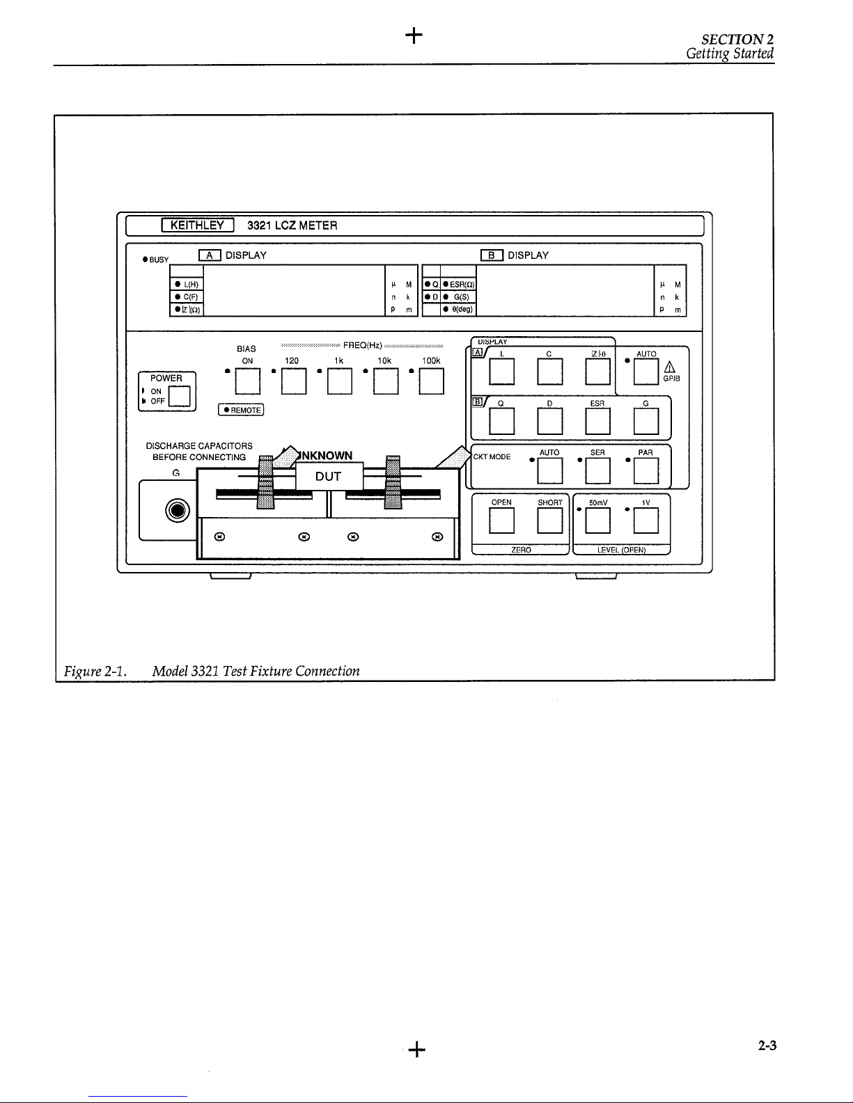
Model 3321 Test Fixture Connection
. . . . . . . . . . . . . . . . . . . . . . . . . . . . . . . . . . . . . . . . . . . . . . ..‘........................................................
2-3
Operation
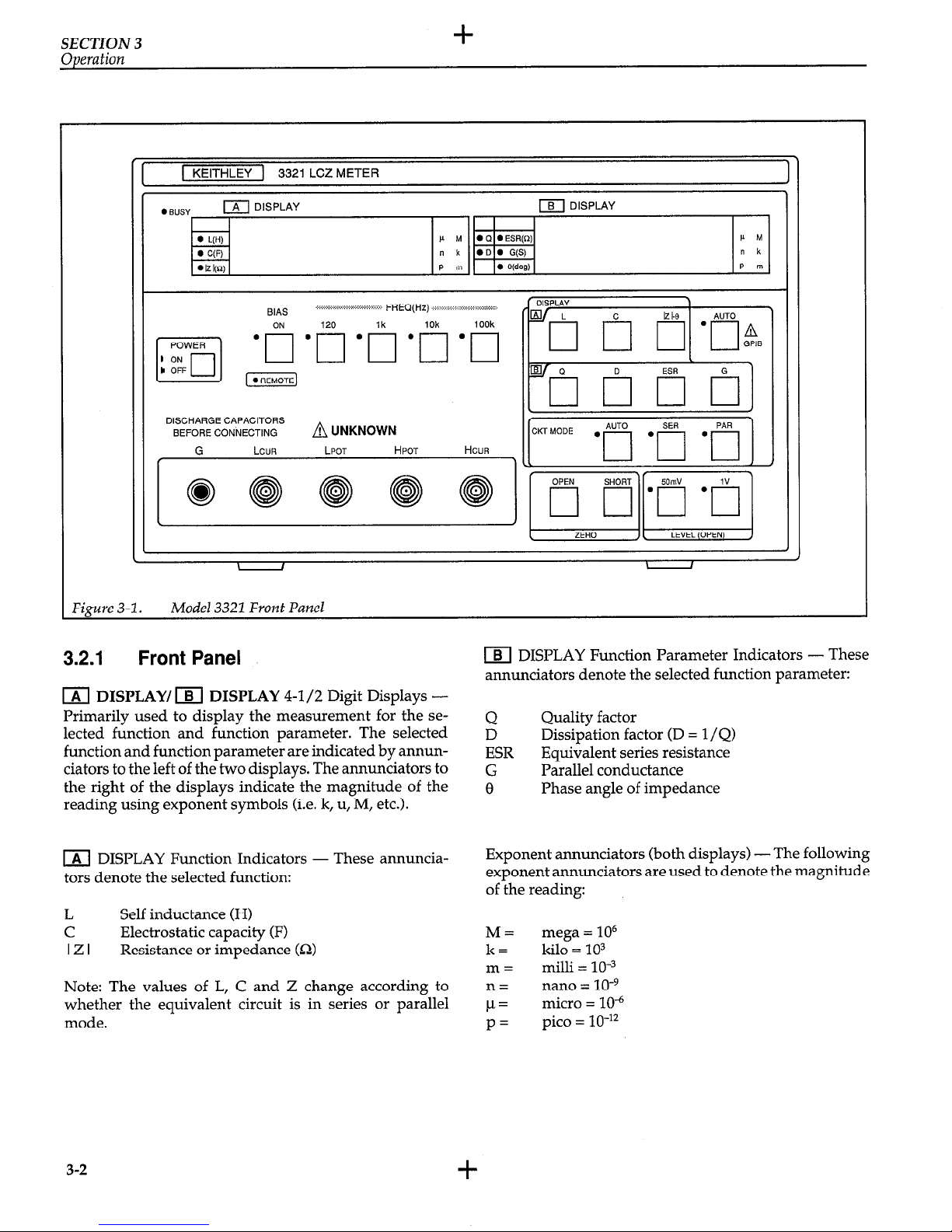
Model 3321 Front Panel
..............................................................................................................................
3-2
Model 3321 Rear Panel..
.............................................................................................................................
3-6
Cleaning Air Filter..
....................................................................................................................................
3-7
Fuse Replacement
.......................................................................................................................................
3-8
_
Connection to the Device Under Test
.......................................................................................................
3- 10
Equivalent Circuits of Device Under Test
................................................................................................
3-11
OPEN Measurement
.................................................................................................................................
3-16
SHORT Measurement
...............................................................................................................................
3-17
Equivalent Circuits of Measurement System
............................................................................................
3-18
Test Cables..
..............................................................................................................................................
3-19
.
111
Page 11
3
Table 3-l
Power-up Defaults.. .....................................................................................................................................
3-9
Table 3-2
AUTO Function Selections
.......................................................................................................................
3-10
Table 3-3
AUTO Equivalent Circuit Selections..
......................................................................................................
3-l 2
Table 3-4
Impedance Ranges
....................................................................................................................................
3-14
Table 3-5
Additional Error of I Z I Caused by Test Cables (Reference Data)
...........................................................
3-20
Table 3-6
Error Message
...........................................................................................................................................
3-2 1
4
GPIB Interface
Table 4- 1
Multi-Line Interface Message..
...................................................................................................................
4-5
Table 4-2
Interface Functions..
....................................................................................................................................
4-6
Table 4-3
Bus Drivers .................................................................................................................................................
4-6
Table 4-4
List of Program Codes ................................................................................................................................
4-9
Table 4-5
Response to Interface Messages
................................................................................................................
4-10
Table 4-6
Status Bytes
...............................................................................................................................................
4-11
Table 4-7
Process Time of Program Codes
(Reference Data)
........................................
. .........................................
4-12
Table 4-8
Setting Messages..
.....................................................................................................................................
4- I4
Table 4-9
Inquiry Messages
......................
.
...............................................................................................................
4-15
Table 4- 10
GPIB Error Messages
................................................................................................................................
4- 19
list of Tables
Operation
Page 12
SECTION 1
General Information
1 .l INTRODUCTION
This section contains general information about the
Model 3321.
1.2 PRODUCT DESCRIPTION
The Model 3321 LCZ Meter is a high accuracy (0.1%
basic accuracy), full function LCZ meter. It includes an
IEEE-488 interface to control operation from a computer.
The Model 3321 drives a device under test (DUT) with a
known voltage sine wave signal. Impedance is derived
by precisely measuring the resultant current that flows
through the DUT.
1.2.1 Condensed Specifications
The following condensed specifications help summarize
the capabilities of the Model 3321. Complete, detailed
instrument specifications are located in Appendix A.
Measurement Functions: L, C, I Z I, Q, D, ESR, G, 8.
These functions can be automatically selected.
Basic Accuracy: 0.1% (at 1kHz)
Measurement Ranges (Display):
IZI
O.lmQ to 19.999Ma
C
O.OOlpF to 199.99mF
b, D
O.lnH to 19.999kH
0.0001 to 19999
8
-180.00” to +179.99”
Measurement Frequency:
120Hz, lkHz, 1OkHz or
1ookHz.
Measurement Signal Level: 1V rms, 50mV rms
Equivalent Circuit: Series, parallel and automatic
DC Bias:
DC Bias: Internal: 2V
External: 0 to *35V
Zero Correction: Automatic (OPEN, SHORT).
Measuring Time: FAST (64ms), MED (150ms), SLOW
(480ms).
1.2.2 Features
l High Accuracy - Basic accuracy of 0.1% with dis-
play resolution of 0.0001 at 4-l /2 digits.
l Wide Frequency Range
- Four frequency selections
in the range from 120Hz to 1OOkHz.
l Two Measurement Signal Levels - Selectable sine
wave signals of 50mV rms or 1V rms can be applied
l-l
Page 13
SECTION 1
General Infbvmation
to the DUT. Also, the signal can be biased by selecting the 2V internal DC bias or by externally applying
a DC bias up to i35V.
Variety of Measurement Functions - In addition to
the conventional functions including L, C, D and Q,
you can also display the equivalent series resistance
(ESR), parallel conductance (G), and polar coordinates expression ( I Z I - 0).
Automatic Function and Range Selection - In addition to the conventional autorange feature, function
and the equivalent circuits can also be automatically
selected.
Built-in DC Bias Power Supply - The built-in
2V DC bias power supply is used to measure the
capacitance of polarized devices such as electrolytic
capacitors and semiconductors.
IEEE-488 Interface - Allows the instrument to be
controlled by a computer.
1.3 WARRANTY INFORMATION
Warranty information is located on the
inside front
cover of this instruction manual. Should
your Model
3321 require warranty service, contact the Keithley representative or authorized repair facility in your area for
further information. When returning the instrument for
repair, be sure to fill out and include the service form at
the back of this manual in order to provide the repair
facility with the necessary information.
1.4 MANUAL ADDENDA
Any improvements or changes concerning the instrument or manual will be explained in an addendum
included with the manual. Be sure to note these changes
and incorporate them into the manual.
1.5
SAFETY SYMBOLS and TERMS
The following symbols and terms may be found on an
instrument or used in this manual.
The symbol !
n
on an instrument indicates that the
user should refer to the operating instructions located in
the instruction manual.
The WARNING heading used in this manual explains
dangers that might result in personal injury or death.
Always read the associated information very carefully
before performing the indicated procedure.
The CAUTION heading used in this manual explains
hazards that could damage the scanner card. Such damage may invalidate the warranty.
1.6 INSPECTION
The Model 3321 was carefully inspected, both electrically and mechanically, before shipment. After unpacking all items from the shipping carton, check for any
obvious signs of physical damage that may have
occurred during transit.
Report any damage to the shipping agent immediately.
Save the original packing carton for possible future
reshipment. The following items are included with
every Model 3321 order:
l Model 3321 LCZ Meter
l Model 3321 Instruction Manual
l Additional Accessories as ordered.
If an additional instruction manual is required, order
the manual package, Keithley part number 3321-901-00.
The manual package includes an instruction manual
and any pertinent addenda.
1.7 OPTIONAL ACCESSORIES
The following accessories are available from Keithley
for use with the Model 3321:
1.
2.
3.
4.
Model 3323 Direct Test Fixture. Allows leaded parts
to be directly inserted into this test fixture.
Model 3324 4-Terminal Alligator Clip Test Lead.
Designed for four-terminal components, in which
the current-supplying terminals and voltagemeasurement terminals are separated.
Model 3325 Kelvin Clip Test Lead. Uses two clips for
four-terminal connections. Used to measure large or
irregularly-shaped components which cannot be
inserted into the Model 3323 test fixture.
Model 3326 Chip Component Test Leads. This
tweezer-type test lead set permits easy connection to
surface mounted chip components.
The cables for all the above test leads are shielded to
minimize stray capacitance.
1.8 SPECIFICATIONS
Model 3321 specifications may be found in Appendix A
of this manual.
l-2
Page 14
SECTION 2
Getting Started
2.1 INTRODUCTION
This brief section will guide the user through front panel
operation. This section is intended to acquaint the user
with basic operation. Detailed operation is covered in
Section 3.
NOTE
Front and rear panel views of the instrument
(which may be helpful in locating controls, annunciators or connectors) are provided by
Figures 3-l and 3-2. These drawings are located in Section 3.
2.2 POWER-UP
The instrument is designed to operate from 90-132V or
198-250V line voltage ranges at 48 to 62Hz. Perform the
following steps to connect the instrument to line power:
1. Check the rear panel LINE SUPPLY selector switch
and make sure the setting agrees with the line voltage available in your area. If the switch setting needs
to be changed, perform the procedures in paragraph
3.3. Keep in mind that changing the line voltage setting requires a fuse change.
CAUTION
To prevent damage to the instrument that
may not be covered by the warranty, make
sure the rear panel LINE SUPPLY switch is
set to the correct line voltage setting.
2. The power cord is supplied with the instrument.
Connect the female end of the power cord to AC receptacle on the rear panel, and connect the other
end to a grounded AC outlet.
WARNING
The instrument is equipped with a 3-wire
power cord that contains a separate ground
wire and is designed to be used with
grounded outlets. When proper connections
are made, instrument chassis is connected to
the power line ground. If the AC outlet is not
grounded, the rear panel safety earth ground
terminal must be connected to a known
safety earth ground using #18 AWG (or
larger) wire.
3. Turn on the instrument by depressing the POWER
switch in to the ON position. The instrument will
perform its power up sequence (see paragraph
3.3.4). After successfully completing the power up
tests, the instrument will assume default conditions
+
2-1
Page 15
SECTION 2
Gettim Started
+
that configure the instrument for immediate measurements.
NOTE
The instrument is ready for immediate use.
However, to achieve rated accuracy, the instrument must be allowed to warm up for at
least l/2 hour.
2.3 BASIC MEASUREMENTS
A measurement is performed by applying a known rms
signal level at a specific frequency to the DUT and then
calculating and displaying the results.
NOTE
The following procedure assumes that the instrument is configured to its power-up default conditions. If you are not sure about the
setup configuration, simply turn the power
off and then on again.
NOTE
The following procedure uses the Model 3323
Test Fixture to connect DUT to the instrument
(see Figure 2-l). If using test cables, make sure
4-terminal connections are used as explained
in paragraph 3.4.
Perform the following steps to make basic L, C or Z measurements:
1. Connect the Model 3323 Test fixture to the instrument. This test fixture allows easy DUT connection
to the instrument, and provides accurate measurements by eliminating the stray capacitance of test cables.
2. Note that automatic function is selected as denoted
by the AUTO annunciator to the left of the yellow
AUTO key. In AUTO function, the instrument will
automatically select the appropriate function (L, C or
Z) for the device connected to it.
3. Install the DUT (device under test) into the test fixture. The appropriate function for the DUT will be
selected and the measurements will be displayed as
follows:
NOTE
The exponent symbol annunciators (p, n, u, m,
k and M) for the readings are located to the
right of each display.
A.
B.
C.
For inductors (L), the m DISPLAY provides
the reading in henries (H), and them DISPLAY
provides the quality factor (Q).
For capacitors (C), the m DISPLAY provides
the reading in farads (F), and them DISPLAY
provides the dissi ation factor (D).
For resistors, the A
i!!b
DISPLAY provides the Z
reading in ohms (a), and them DISPLAY provides the phase shift (0) of approximately 0”.
The above procedure requires no instrument settings by
the operator. The test is completely automated by simply
using the power-up default setup configuration to test
DUTs. Of course this setup configuration is not desirable
for all measurements and thus, requires the operator to
modify appropriate operating parameters, such as the
test signal level and frequency.
The test signal level and frequency can be modified as follows:
Signal Level - On power up, the test signal level is set to
1V rms as denoted by the front panel 1V LEVEL annunciator. To select the alternate signal 1eveL (50mV rms),
simply press the 50mV LEVEL key on the front panel.
Signal Frequency - On power up, the test frequency is
set to 1kHz as denoted by a FREQ annunciator. To select
one of the other frequencies (lOkHz, 1OOkHz or 120Hz),
press and release the appropriate FREQ key.
2-2
+
Page 16
+
SECTION 2
Getting Started
1-1
3321 LCZ METER
I
1
ZERO
Jl LEVEL (OPEN) j
J
ciauve 2-l.
Model 3322 Test Fixture Connection
+
2-3
Page 17
+
SECTION 3
Operation
3.1 INTRODUCTION
ciators and connectors on the front and rear panels of the
instrument.
This section covers front panel operation. For operation
over the GPIB bus, see Section 4.
3.2 FRONT AND REAR PANEL
FAMILIARIZATION
The front and rear panels of the instrument are shown in
Figure 3-l and Figure 3-2.
The following information describes the controls, annun-
+
3-l
Page 18
SECTION 3
I
-1 3321 LCZMETER
I
l BUSY
m DISPLAY
m DISPLAY
l L(H)
C M
l a l ESR(O)
P M
. C(F)
n k 0 D 0 G(S)
n k
. h I,“\ D m l olden1 P m
BIAS
.:.-..:.:.:.:.<.:.:.:.:.:.:.:.:.:.,.:.:. FREQ(Hz) :.: ..:.:.:.:.:. :.:.:.:.:.:.: :.:.:.:.ix.:.:
DISCHARGE CAPACITORS
BEFORE CONNECTING
A UNKNOWN
I
\
II
ZERO
)I LE”EL,OPEN) j
I
I
\
I
\
I
Figure 3-1.
Model 3321 Front Panel
3.2.1 Front Panel
IAl DISPLAY/ m DISPLAY 4-l/2 Digit Displays -
Primarily used to display the measurement for the selected function and function parameter. The selected
function and function parameter are indicated by annunciators to the left of the two displays. The annunciators to
the right of the displays indicate the magnitude of the
reading using exponent symbols (i.e. k, u, M, etc.).
m DISPLAY Function Indicators - These annuncia-
tors denote the selected function:
L
Self inductance (H)
C Electrostatic capacity (F)
IZI Resistance or impedance (0)
Note: The values of L, C and Z change according to
whether the equivalent circuit is in series or parallel
mode.
m DISPLAY Function Parameter Indicators - These
annunciators denote the selected function parameter:
Q
Quality factor
D
Dissipation factor (D = 1 /Q)
ESR
Equivalent series resistance
G
Parallel conductance
8
Phase angle of impedance
Exponent annunciators (both displays) - The following
exponent annunciators are used to denote the magnitude
of the reading:
M= mega = lo6
k=
kilo = 103
m=
milli = 10”
n= nano = 10eg
P=
micro = lo4
P’
pica = 1O-‘2
3-2
Page 19
+
SECTION3
Operation
Front Panel Indicators:
BUSY-This indicator lights when a measurement is be-
ing made. This indicator is off while in OPEN or SHORT.
REMOTE -This indicator is on when the GPIB interface
is in the remote state. While in remote, the front panel
controls are disabled.
FREQ (Hz) -
Denotes the frequency (120H2, lkHz,
1OkHz or 1OOkHz) that was selected using the FREQ keys.
CKT MODE
- Denotes the equivalent circuit that was
selected using the CKT MODE keys.
AUTO Automatic selection mode; SER or PAR auto-
matically selected.
SER Series equivalent circuit.
PAR
Parallel equivalent circuit.
Note: CKT selections only affect readings on m DISPLAY.
LEVEL (OPEN)- Denotes the level of the measurement
signal that was selected using the LEVEL keys.
50m
50mV rms signal level. Basic accuracy is lowered
using this level.
1
Standard 1V rms signal level.
The indicated signal level is the voltage applied to the
output while under a “no load” condition. The output
impedance of the signal source is approximately 1OOfi.
When connecting the signal to a device that has an impedance of less than lkS& loading will cause the signal
level to drop below the indicated voltage level.
Front Panel Controls:
POWER ON-OFF
The “in” position turns power on and the “out” position
turns power off. After turning power off, wait at least
three seconds before turning it back on.
BIAS ON Key
Pressing this key enables the internal 2V bias power supply. Pressing the key a second time disables the bias supply. With the rear panel BIAS INT/EXT switch set to the
EXT position, the BIAS ON key will instead control the
externally applied bias supply.
NOTE
The bias supply can only be enabled with the
C (capacitance) function selected and AUTO
function disabled.
FREQ (Hz) Keys:
These keys are used to select the frequency of the measurement signal. The enabled annunciator denotes which
frequency is selected.
120 - Pressing this key sets the measurement frequency
to 120Hz.
lk - Pressing this key sets the measurement frequency
to 1kHz.
10k -Pressing this key sets the measurement frequency
to 10kHz.
100k -
Pressing this key sets the measurement fre-
quency to 1 OOkHz.
m DISPLAY Keys:
The following keys are used to select the measurement
function. The reading for the selected function is shown
on them DISPLAY. The default function parameter (Q,
D or 0) for the selected function is automatically selected
and shown on the m DISPLAY.
L - Pressing this key selects the inductance (L) function
and displays the reading in henries (H). The selected default function parameter is Q.
C-Pressing this key selects the capacitance (C) function
and displays the reading in farads (F). The selected default function parameter is D.
121-e-- Pressing this key selects the impedance (Z)
function and displays the reading in ohms (a). Note that
this function is used to measure resistance. The phase an-
le (0)
I5
for the impedance measurement is shown on the
B DISPLAY.
+
3-3
Page 20
SECTION 3
Operation
+
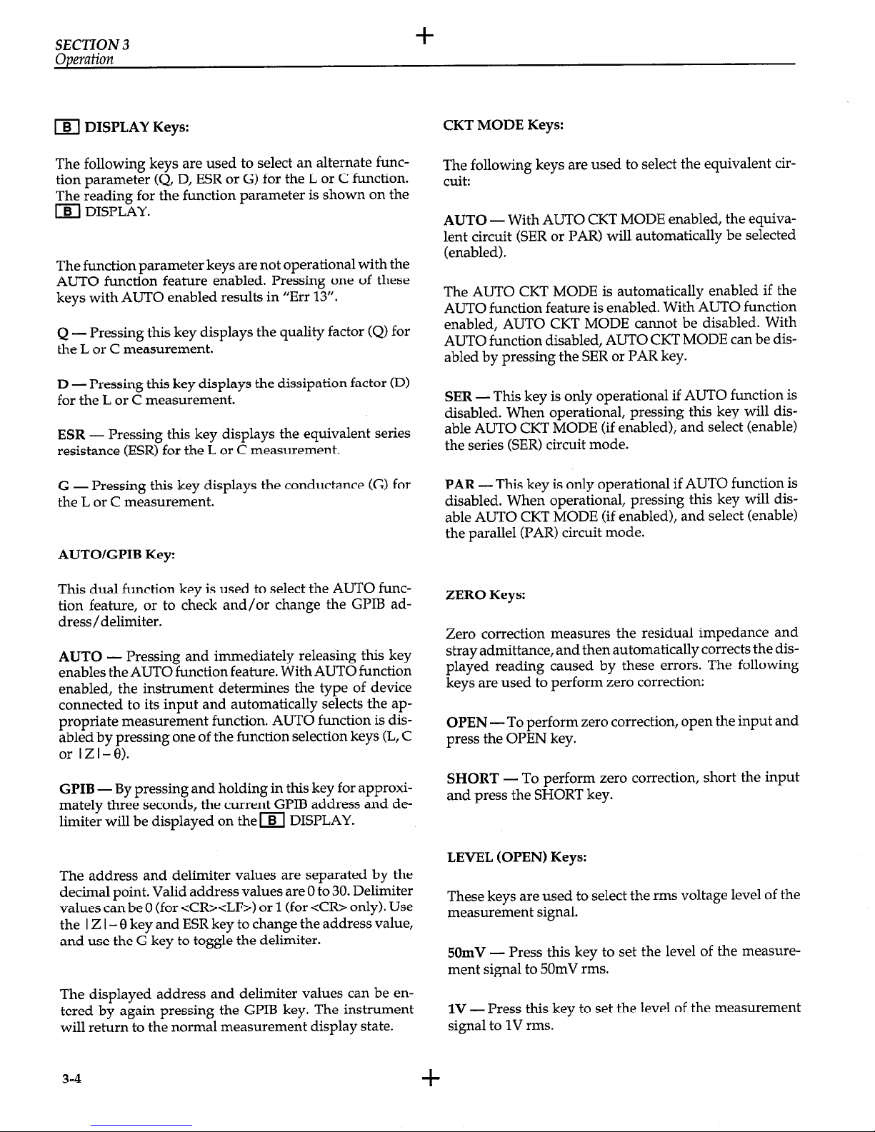
m DISPLAY Keys:
The following keys are used to select an alternate function parameter (Q, D, ESR or G) for the L or C function.
The reading for the function parameter is shown on the
m DISPLAY.
The function parameter keys are not operational with the
AUTO function feature enabled. Pressing one of these
keys with AUTO enabled results in “Err 13”.
Q - Pressing this key displays the quality factor (Q) for
the L or C measurement.
D - Pressing this key displays the dissipation factor (D)
for the L or C measurement.
ESR - Pressing this key displays the equivalent series
resistance (ESR) for the L or C measurement.
G - Pressing this key displays the conductance (G) for
the L or C measurement.
AUTO/GPIB Key:
This dual function key is used to select the AUTO func-
tion feature, or to check and/or change the GPIB address/delimiter.
AUTO
- Pressing and immediately releasing this key
enables the AUTO function feature. With AUTO function
enabled, the instrument determines the type of device
connected to its input and automatically selects the appropriate measurement function. AUTO function is disabled by pressing one of the function selection keys (L, C
or IZI-0).
GPIB - By pressing and holding in this key for approxi-
mately three seconds, the current GPIB address and de-
limiter will be displayed on them DISPLAY.
The address and delimiter values are separated by the
decimal point. Valid address values are 0 to 30. Delimiter
values can be 0 (for <CR><LF>) or 1 (for <CR> only). Use
the I Z I - 0 key and ESR key to change the address value,
and use the G key to toggle the delimiter.
The displayed address and delimiter values can be entered by again pressing the GPIB key. The instrument
will return to the normal measurement display state.
3-4
+
CKT MODE Keys:
The following keys are used to select the equivalent circuit:
AUTO -With AUTO CKT MODE enabled, the equiva-
lent circuit (SER or PAR) will automatically be selected
(enabled).
The AUTO CKT MODE is automatically enabled if the
AUTO function feature is enabled. With AUTO function
enabled, AUTO CKT MODE cannot be disabled. With
AUTO function disabled, ALIT.0 CKT MODE can be dis-
abled by pressing the SER or PAR key.
SER - This key is only operational if AUTO function is
disabled. When operational, pressing this key will disable AUTO CKT MODE (if enabled), and select (enable)
the series (SER) circuit mode.
PAR - This key is only operational if AUTO function is
disabled. When operational, pressing this key will disable AUTO CKT MODE (if enabled), and select (enable)
the parallel (PAR) circuit mode.
ZERO Keys:
Zero correction measures the residual impedance and
stray admittance, and then automatically corrects the displayed reading caused by these errors. The following
keys are used to perform zero correction:
OPEN -To perform zero correction, open the input and
press the OPEN key.
SHORT
- To perform zero correction, short the input
and press the SHORT key.
LEVEL (OPEN) Keys:
These keys are used to select the rms voltage level of the
measurement signal.
50mV
- Press this key to set the level of the measure-
ment signal to 50mV rms.
1V - Press this key to set the level of the measurement
signal to 1V rms.
Page 21

+
SECTION 3
Operation
Measurement Terminals:
UNKNOWN-The following front panel connectors are
used to connect the DUT to the instrument:
L CUR - Current detection terminal
L POT - Voltage detection terminal (Low)
H POT - Voltaie detection terminal (High)
H CUR - Drive signal output terminal.
G -Ground terminal that is connected to the chassis
of the instrument. Used for shielding.
The bias voltage and the drive signal can be monitored on
these terminals.
+
3-5
Page 22

SECTION 3
Operation
WARNING
-/%
NO INTERNAL OPERATOR
Figure 3-2. Model 3321 Rear Panel
CAUTION
FOR FIRE PROTECTION,
SERVICEABLE PARTS. SERVICE
3.2.2 Rear Panel
CAUTION
0 to *35V is the maximum voltage that can be
GLIB - This connector is used to connect the GPIB
applied to the BIAS IN connector. Voltages out-
interface of the instrument to GPIB interface of a com-
side this range may blow the fuse and cause
puter. See Section 4 for details.
damage to the instrument.
BIAS -The following switch, fuse and input connector
pertain to using an external bias supply:
INT/EXT Switch - This toggle switch is used to
switch between the built-in (INT) bias power supply (2V) and the externally (EXT) applied bias supply (up to 35V).
Fuse - Maintenance fuse for the external power
supply (O.lA quick acting type).
IN Connector - BNC connector used to connect the
external bias supply to the instrument power input connector. Use a 0 to +35V supply with low ripple and
noise.
Ventilation Fan - The fan is used to keep the inside of
the instrument free from damaging heat build-up. The
fan pulls cool air into the instrument and expels warm
air out of the vents in the top cover. For proper
ventilation:
1. Maintain at least 10cm between the rear panel and a
wall.
2. Do not block the air vents in the top cover.
3. Clean the air filter periodically to prevent clogging.
Figure 3-3 shows how to remove the filter for
cleaning.
WARNING
Be sure to turn off the power and remove the
power cord before removing or installing the
filter.
3-6
Page 23

+
SECTION 3
Operation
Rear Panel
(2) Remove and Clean
Air Filter
Figure 3-3.
Cleaning Air Filter
(1) Remove the inner holder
LINE SUPPLY-Set this switch to the available line voltage. Changing the line voltage setting will require a fuse
change. See paragraph 3.3.1 for details.
LINE 4%62Hz - Power Receptacle and Fuse. Use the
supplied line cord to connect the instrument to the line
power. Fuse replacement is covered in paragraph 3.3.2.
CAUTION
To prevent damage to the instrument that
may not be covered by the warranty, be sure
to turn off power and disconnect the line
cord before changing the line voltage setting. Do not use a fuse other than the one
specified for the line voltage setting.
3.3 POWER-UP PROCEDURE
3.3.1
Line Voltage Setting
The instrument is designed to operate from 90-l32V or
19%250V line power ranges at 48 to 62Hz. Perform the
following procedure to set the line voltage:
WARNING
Make sure the instrument is disconnected
from the power line and all other equipment
before proceeding.
Safety Ground Terminal - If the instrument is not con-
netted to a safety earth ground through the supplied
3-prong line cord, connect this terminal to a known safety
earth ground using #18 AWG (or larger) wire.
1. Check the line voltage setting of the LINE SUPPLY
switch on the rear panel. To change the setting, use a
flat-blade screw driver to set the rotary switch to the
setting that best matches the available line power.
+
3-7
Page 24

SECTION 3
Operation
2. If the switch setting was changed, install a fuse consistent with the operating voltage as described in the
next paragraph.
3.3.2 Fuse Replacement
A rear panel fuse located inside the AC LINE receptacle
is used to protect the power line input of the instrument.
If the fuse needs to be replaced (line voltage switch setting changed or blown fuse), perform the following
steps:
WARNING
Make sure the instrument is disconnected from
the power line and other equipment before
replacing the fuse.
1. Using a flat-blade screw driver, pry open the fuse
drawer as shown in Figure 3-4.
‘igure 3-4. Fuse Replacement
2. Remove the fuse from the fuse clip. Notice that there
is a spare fuse in front of it.
3. Replace the fuse with the following type:
Line
I----
Voltage
1oov/12ov
22OV/24OV
Fuse Rating
0.4A
0.5A
0.2A
0.25A
CAUTION
Do not use a fuse with a higher current rating
than specified, or instrument damage may occur.
4. Push the fuse drawer back into the receptacle.
3.3.3 Power Cord
Connect the female end of the power cord to the AC
receptacle on the rear panel of the instrument. Connect
the male end of the cord to a grounded AC outlet.
WARNING
The instrument is equipped with a 3-wire
power cord that contains a separate ground wire
and is designed to be used with grounded outlets. When proper connections are made, instrument chassis is connected to the power line
ground. If the AC outlet is not grounded, the
rear panel safety earth ground terminal must be
connected to a known safety earth ground using
#18 AWG (or larger) wire.
CAUTION
Be sure that the power line voltage agrees with
the indicated voltage of the LINE SUPPLY
switch. Failure to observe this precaution may
result in instrument damage not covered by the
warranty.
3.3.4 Power Up Sequence
To turn on the instrument, depress the POWER button.
During the power up cycle, the unit will perform the
following:
1. All annunciators and display segments will turn on
for a few seconds. This allows you to check for defec-
tive indicators or display digits.
2. The revision level of the firmware is displayed
briefly on the IAl DISPLAY. For example:
-l.lO-
3. The self-check on memory elements and self-
calibration of internal circuits are performed. During
this eriod, the “CAL” message will be displayed on
the b A DISPLAY and a countdown from 7 to 0 will
take place on the m DISPLAY. Any errors that
occur are denoted by error messages on the display.
Table 3-6 explains the error messages.
4. The unit will begin normal operation in accordance
with the power-up configuration discussed in the
next paragraph.
3-8
Page 25

+
SECTION 3
Operation
3.3.5
Default Conditions
3.4 TEST CONNECTIONS
Default conditions are the setup conditions that the in-
In general, 4-wire measurements are made on the device
strument will return to when the instrument is powered under test using the front panel BNC type terminals. A
up (or when a DCL or SDC command is sent over the
test fixture, such as the Model 3323 which connects diGPIB bus). The default conditions for the instrument are
rectly to the front panel, or test cables can be used to make
summarized by Table 3-1.
connections to the DUT.
Table 3-1. Power-up Defaults
The UNKNOWN terminals are described as follows:
Parameter
m DISPLAY
m DISPLAY
CKT MODE
FREQ
DELAY
LEVEL
Zero correction
BIAS
Header output
SRQ output
Address
Delimiter
Setting
AUTO
(AUTO)
AUTO
1kHz
Zero
1Vrms
No correction
Off
Inhibit (GPIB “HD 0”)
Inhibit (GPIB “RQ 0” )
2
<CR> <LF>
Remark
1
1
1
1
1,2,3
1,2
Remarks:
1. The setting for this parameter cannot be saved in one of the ten
battery back-up memories. The setting for all other parameters
can be returned to the power-down condition by recalling
Memory 0.
2. The setting for this parameter is stored in battery backed-up
memory and automatically returns to the last programmed value
on power-up.
3. Address 2 is factory default, but can be changed by the user.
G-Ground terminal for guard that can be used to shield
the DUT.
L CUR - Current detection terminal
L POT - Voltage detection terminal (Low)
H POT - Voltage detection terminal (High)
H CUR - Drive signal output terminal. Delivers the DC
bias and the sine wave signal.
When using individual cables, refer to Figure 3-5 and use
the following rules to connect them:
1. Connect the voltage detection terminals (H POT and
L POT) to the inner position on the DUT leads as
shown in the illustration.
2. Keep cables as short as possible.
3. If using long cables, twist the two voltage cables together, then twist the two current cables together. Finally, twist the two separate cable pairs together to
form one twisted cable assembly.
4. At the DUT, connect the shields of the BNC cables together.
+
3-9
Page 26

SECTION 3
Operation
1
Figure 3-5.
Connection to the Device Under Test
Arrangement of
cables for twisting
(See Figure 3-l OA)
3.5 BASIC MEASUREMENTS
To achieve rated accuracy, zero correction must first be
performed as explained in paragraph 3.9. In general, zero
correction is performed by first opening the measurement terminals and pressing the OPEN key. After completion of the OPEN correction, the terminals are then
shorted and the SHORT key is pressed.
I Z I - 0 (Q) - Resistance or impedance
To manually select the desired function, simply press
and release the appropriate m DISPLAY key.
Automatic Function Selection - When AUTO is enabled, the instrument selects the function, function parameter and equivalent circuit automatically. It does this
by measuring the phase angle (f3) of the DUT connected at
the input. Table 3-2 defines the selected function and
function parameter that is based on the internally measured phase angle (e):
3.5.1
Measurement Function Selection
The basic measurement functions are selected using the
@l DISPLAY keys or the yellow AUTO key. The se-
lected function is denoted by the annunciators located to
the left of them DISPLAY. The measurement of the selected function is provided on them DISPLAY. The exponent annunciators for the measured reading are located to the right of the m DISPLAY. Available functions include:
AUTO - Automatic function selection. With AUTO
function selected, the instrument will determine the type
of device connected to the input and automatically select
the appropriate measurement function.
L (H) - Self-inductance (self-induction factor)
C (F) - Electrostatic capacity
Table 3-2.
AUTO Function Selections
Internally Measured Function
Phase Angle (0) Function Parameter
3-10
+
Page 27

+
SECTION 3
Operation
While in AUTO function:
1. Function parameters are automatically selected.
Pressing any m DISPLAY key will result in “Err
13”.
2. The equivalent circuit (CKT) is automatically
(AUTO) selected (SER or PAR).
3.5.2 Measurement Function Parameter
Selection
The measurement arameter for the selected function is
selected using the B
b
DISPLAY keys. Note however,
that if AUTO function is enabled, these keys are inoperative (Err 13). In AUTO function, the measurement pa-
rameter is automatically selected.
The selected function parameter is denoted by the annunciator located to the left of the m DISPLAY. The
m DISPLAY provides the reading of the selected parameter, while the exponent part of the reading is located
to the right of the display. The available function parameters include:
Q - Quality factor
D - Dissipation factor (D = 1 /Q)
ESR (a) - Equivalent series resistance
G (S) - Parallel conductance
8 (deg) - Phase angle of impedance
Note that there is not a separate key to select 9 (Deg). 8
(Deg) is automatically selected when I Z I-8 function is
selected.
To select the desired function parameter (AUTO off),
simply press and release the appropriate m DISPLAY
key.
When ESR or G is selected, the equivalent series resistance, or parallel conductance is displayed, respectively.
The readings for Q, D and 8 are not related to the equivalent circuit.
3.5.3
Equivalent Circuit Selection
The equivalent circuit (see Figure 3-6) is selected using
the CKT MODE keys. Note that if AUTO function is enabled, the CKT MODE keys are inoperative (Err 15) and
the equivalent circuit is placed in the AUTO mode.
SER (series) PAR (parallel)
I Figure 3-6. Equivalent Circuits of Device Under Test
The CKT annunciators on the front panel denote the selected equivalent circuit. The equivalent circuit selections
include:
AUTO - Automatic equivalent circuit selection
SER - Series Circuit
PAR - Parallel Circuit
To manually select the equivalent circuit (assuming
ATJTO function is disabled), simply press and release the
appropriate CKT MODE key.
With AUTO CKT MODE enabled, the instrument selects
an equivalent circuit automatically. The selected circuit is
determined according to the combination of selected
function, function parameter, and phase angle. Table 3-3
summarizes the combinations that determine the equivalent circuit while AUTO CKT is enabled.
3-11
Page 28

SECTION 3
Table 3-3. AUTO Equivalent Circuit Selections
3.5.4
Measurement Range Selection
Measurement Capabilities
Conditions for selection of
Conditions for selection of
series mode (SER)
parallel mode (PAR)
Function Function
Function
Parameter Function Parameter
ESR
?: (IZI 11wZ) Q,D
L, c
G
lil’
L,C,(lZl >lw1) Q,D
0
Measurement range selection for the selected function is
performed automatically. Reading range for the function
parameter (m DISPLAY) is also selected automatically.
The measurement capability of each function and func-
tion parameter is summarized as follows:
IZI, ESR
The instrument will go to the optimum (most accurate)
range to make the measurement.
4 l/2 digits (19999 digits max>.
Table 3-4 lists the impedance ranges for the instrument.
Notice that the valid measurement range is frequency
and level dependent. The reading limits for each range
are defined by the Lower Limit Extension and the Upper
Limit Extension. The instrument will not measure levels
that fall outside of these limits.
The optimum measurement is performed and displayed
120Hz
: O.OOOnF to 199.99mF
on the range that is bounded by the Lower Limit and Up-
1kHz : O.OpF to 19.999mF
per Limit (see Table 3-4). For example, for a 1Om meas-
1OkHz
: O.OOpF to 1.999mF
urement, the displayed reading will occur on Range 3.
1ookHz
: O.OOOpF to 199.99yF
Hysteresis - A hysteresis of approximately 10% is used
to keep the instrument from changing ranges for a reading that varies along the borderline of two ranges. When
a reading is increasing, the instrument will up range immediately after 19,999 counts. For example, on Range 2,
assume a reading of 1.9999w2. If the reading increases by
one count, the instrument up ranges and reads 2.000 Wz
on Range 3. When the reading is decreasing, the instrument will down range after 1800 counts. Continuing with
the same example, a decreasing reading will read 1.800
162 on Range 3. When the reading decreases one more
count, the instrument will down range to Range 2 and
read 1.7999 kfi. Thus, a window of 200 counts is provided
for reading variances.
C
Type: Exponent representation
Resolution:
4 l/2 digits (19999 max)
Range: O.OOOpF, +(O.OOlpF to 199.99mF)
The range of I C I changes according to
frequency:
L
Type: Exponent representation
Resolution: 4 l/2 digits (19999 max)
Range: O.OnH, rt(O.lnH to 19.999kH)
The range of I L I changes according to
frequency:
120Hz
: O.OpH to 19.999kH
1kHz
: O.OOpH to 1.9999kH
1OkHz
: 0.OOOu.H to 199.99H
1ookH
: O.OnH to 19.999H
3-12
+
Page 29

+
SECTION 3
Operation
Q,D
Type: Floating-point representation
Resolution:
4 l/2 digits (19999 max)
Range: .oooo, +(.oool to 19999)
8
Type:
Resolution:
Range:
Fixed-point representation
0.01”
-180.00° to +179.99O
Deviation
Range information for deviation is covered in
paragraph 3.6.3.
Calculating Admittance and Susceptance
Admittance Y ( I Y I and Qy) and susceptance B are not
displayed by the instrument, but can be calculated as fol-
lows:
IYI =l/lZl
0y=-0
B= IYI l Siney=-X/&2+X2)
where; Rs is the value of R (=ESR) for the series equivalent circuit (SER).
3-13
Page 30

SECTION3
Operation
+
Table 3-4.
Impedance Ranges
Applied Impedance Range 622)
Reference
Lower Limit Lower Limit Upper Limit Upper Limit
Level Frequency
Range Resistance 62) Extension
**
***
Extension
1v 120Hz *1 100
- 0 5
11
1kHz 2 100
0.9 5 2k
11 k
10kHz 3 lk
980 2k 20 k
110 k
4 10 k
9.8 k 20 k 200 k
l.lM
5 50 k
49 k 200 k 2M
5.5M
"6
50 k 450 k 2M 20M
co
1ookHz *1 100
- 0 5
11
2 100
0.9 5 2k
11 k
3 lk
980 2k 20 k
110 k
4 10 k
9.8 k 20 k 200 k
1.1 M
"5 10 k
90 k
200 k 2M
00
*6 10 k
90 k 200 k 2M
Co
50mV 120Hz “1 100
- 0 5
11
1kHz 2 100
0.9 5 2k
11 k
1 OkHz 3 lk
900 2k 20 k
110 k
4 10 k
9k 20 k 200 k
l.lM
5 50 k
45 k 200 k 2M
5.5M
*6
50 k
450 k
2M 20M
w
1OOkHz *1 100
- 0 5
11
2 100
0.9 5 2k
11 k
3 lk
900 2k 20 k
110 k
4 10 k
9k 20 k 200 k
l.lM
"5 10 k
90 k
200 k 2M
c-a
*6 10 k
90 k
200 k 2M
00
*Extension range
**Lower limit values are inclusive.
***Upper limit values are not inclusive.
3-14
+
Page 31

SECTION 3
Operation
3.6 FREQUENCY SELECTION
The impedance of a device under test changes with frequency. Therefore, it is advisable to measure the device
at its operating frequency.
Use the following guidelines to select a measurement
frequency:
120Hz: Use to measure large values of C
1kHz: Use to measure intermediate values of R, L
and C
1OkHz and 1OOkHz: Use to measure small values of
LandC
To select one of the four measurement frequencies
labeled on the front panel (120Hz, lkHz, lOk.Hz,
lOOkHz), press and release the appropriate FREQ key.
The selected frequency is denoted by the enabled
annunciator.
3.7 SIGNAL LEVEL SELECTION
The instrument measures devices by applying an rms
signal (at the selected frequency) and then measuring
the subsequent current. The signal levels that can be
selected are 50mV rms and 1V rms.
The IV signal level can be used for most measurements.
For semiconductors that have non-linear characteristics
that are affected by signal magnitude, use the 50mV
level.
The front panel LEVEL annunciator denotes the current
signal level. To select the alternate level, simple press
the 50mV or 1V key.
The specified signal levels are maintained for devices
that have an impedance of lm or more. At lower
impedances, loading lowers the level of selected signal.
Note: After a signal level is selected, the displays will
blank until the next measurement is completed.
3.8 DC BIAS
When measuring capacitance (C), a DC bias can be
applied. This b ias allows capacitance changes in
semiconductor junctions due to applied voltage to be
measured.
The instrument has a built in 2V bias that can be used,
or an external bias voltage from 0 to *35V can be
applied via a BNC connector on the rear panel. The bias
voltage (and drive signal) can be monitored on the H
CUR terminal.
DC bias cannot be used to measure L, R or Z. Pressing
the BIAS key while in one of these functions will result
in “Err 14”.
Bias Stabilization Time - When bias is abruptly
changed by turning BIAS on to its peak value, some
time is required to allow the bias voltage to stabilize
before an accurate capacitance measurement can be
made. Use the following equation to determine the time
required to achieve stability:
Stabilization time (in seconds) = 4 + 0.015C
where; C is the capacitance in PF
Perform the following steps use DC bias:
1.
2.
3.
4.
If using an external supply, connect it to the BIAS
EXT IN BNC connector on the rear panel. Make sure
the supply is in standby and is set for OV.
CAUTION
To prevent damage to the instrument, do not
apply voltage that is not within the OV to f35V
range. Also, adhere to the precautions and considerations explained affer this procedure.
Set the rear panel BIAS switch. If using the internal
supply, set the toggle switch to the INT 2V position.
If using an external bias supply, set the toggle switch
to the EXT position.
Using the (A( DISPLAY keys, select the C function.
Note that AUTO function must be disabled. DC bias
cannot be enabled in AUTO function.
Connect the device to be measured.
CAUTION
When checking a polarized device, make sure to
observe polarity. Also, make sure to discharge
capacitors before connecting them to the input.
3-15
Page 32

SECTION 3
Operation
5. Enable DC bias by pressing the BIAS key. When
BIAS is enabled, its annunciator will turn on. Note
that if a different function is selected, BIAS will
disable.
6. If using an external bias source, increase the bias
source gradually from zero to the desired level.
7. The capacitance reading using a DC bias will be
displayed.
8. If using an external bias source, gradually decrease
the level to OV.
9. Disconnect the device.
External Bias Supply Precautions and Considerations:
1. Ripple and Noise - The power supply must have
low ripple and noise (4mV rms). It is recommended
that a switching type power supply not be used. If
ripple and noise are large, measurement accuracy is
lowered.
2. Measuring Large Capacitors with High Voltage -
When measuring more than 100pF using a bias of
more than lOV, connect the capacitor to the input
with the bias supply set to OV, and then increase the
voltage gradually. After completing the measurement, decrease the voltage gradually to OV and then
disconnect the device.
3. Voltage Regulation -
For a bias voltage of 1OV or
more, the voltage level must be changed at a slow
rate of speed (<lOV/sec). Otherwise, the EXT O.lA
protection fuse (accessed from the rear panel) will
blow.
3.9 ZERO CORRECTION
Zero correction is performed to cancel the effects of
residual impedance and stray admittance caused by test
fixtures and test cables.
3.9.1
Zero Correction Procedures
OPEN - Stray Admittance Measurement:
Perform the following steps to perform the OPEN correction procedure:
1. Open the measurement terminals as shown in
Figure 3-7.
2. Press the OPEN key. The instrument measures the
stray admittances for all frequencies and stores the
values in memory. On the IA/ DISPLAY, the message
“OP 9” will be displayed. During the execution of
the correction, the display will count down to
“OP 0”, which signals the end of the correction procedure. The instrument will then return to the normal measurement state using the corrected values to
calculate readings. Note that during the execution of
the correction procedure, stray capacitance readings
will be displayed on the m DISPLAY.
NOTE
For the OPEN correction, make sure L CUR is
connected to L POT, and H POT is connected to
H CUR as shown in Figure 3-7.
L POT
H POT
H CUR
Figure 3-7. OPEN Measurement
SHORT - Residual Impedance Measurement:
Perform the following steps to perform the SHORT correction procedure:
1. Short the measurement terminals as shown in
Figure 3-8.
2. Press the SHORT key. The instrument measures the
residual impedance for all frequencies and stores the
values in memory. On the m DISPLAY, the message
“SH 9” will be displayed. During the execution of
the correction, the display will count down to
“SH 0”, which signals the end of the correction procedure. The instrument will then return to the normal measurement state using the corrected values to
calculate readings. Note that during the execution of
the correction procedure, residual impedance read-
ings will be displayed on the fel DISPLAY.
3-16
Page 33

+
SECTION 3
Operation
NOTE
For the SHORT correction, make sure L CUR,
L POT, H POT and H CUR are all connected
together as shown in Figure 3-8.
L CUR L POT H POT
H CUR
Figure 3-8.
SHORTMeasurement
I
3.9.2
Equivalent Circuits of
Measurement System
If the correction values obtained and stored in memory
are represented by measurement circuits shown
Figure 3-9 use the following equation to calculate the true
impedance:
Zx= l/(Ym-Ypp)-Zss
3.9.3 Correctable Range
I Zss I < approx. 3R (Rss < approx. 3Q Lss < approx. 5yH
at 1OOkHz)
I Ypp I < approx. 10~s (Rpp = l/Gpp > approx. 1OOkQ
Cpp < approx. 16pF at 1OOkHz)
If a value exceeds the correctable range, an error results,
an the correction factor (value of zero) does not change.
The instrument measures the overall impedance including residual impedance and stray admittance, and then
corrects the residual impedance and the stray admittance
by calculation. Therefore, if the magnitude of the residual
impedance or stray admittance comes close to the magni-
tude of the measured impedance, or if the two magnitudes are reversed, the measuring accuracy is lowered. In
this case, calibrate the instrument using an external standard.
3.10 MEASUREMENT CABLES
3.10.1 Cable Requirements
When using the cables, maintain the four-terminal configuration all way to the deviceunder test. Use the coaxial
cables, and twist them as illustrated in Figure 3-10(a).
Make sure the cables are arranged as shown in the crosssectional view to minimize errors when performing low
impedance measurements. If it is impossible to bundle
the four cables, twist the two current cables together, and
then twist the two voltage cables separately. The shorter
the cables, the less the error.
Perform the OPEN and SHORT zero correction under
conditions that are similar to the actual measurement
condition. In other words, leave the cables connected to
the instrument, and perform the open and short at the
DUT end of the cables.
Low Impedance Measurements:
Model 3324 4-Terminal Alligator Clip Test Leads - If
possible, twist the two current leads and the two voltage
leads separately as shown in Figure 3-10(b).
Model 3325 Kelvin Clip Test Leads - If possible twist the
two leads together as shown in Figure 3-10(c).
High Impedance Measurements:
When measuring high impedances (i.e. low capacitance
at high frequency) use cables that are shielded all the
way to the test clips. This will minimize stray capacitance
between high and low. The Models 3324 and 3325 test
leads are properly shielded for this application.
+
3-17
Page 34

SECTION3
Operation
+
Y m : Virtual admittance
(Z ss)
(Y PP)
Z x : Measured impedance
Z ss : Residual impedance (series)
R ss
L ss
+Ym
R ss : Residual resistance
L ss : Residual inductance
Y pp : Stray admittance (parallel)
G pp : Stray conductance
C pp : Stray capacity
(a) Normal measurement mode
R ss
L ss
r-
c-zss
(b) OPEN measurement mode
(c) SHORT measurement mode
Figure 3-9. Equivalent Circuits of Measurement System
3-18
+
Page 35

+
SECTION 3
Operation
(a) How to bundle cables
Cross-sectional view
HCUR /HPOT
LCUR / LPOT
(b) Model 3324
(c) Model 3325
ciguve 3-20.
Test Cables
+
3-19
Page 36

SECTION 3
Operation
+
3.10.2 Additional Error
The accuracy specifications are based on making meas-
urements at the input connectors of the instrument.
When using cables to connect to a DUT, additional error
is introduced due to stray capacitance and voltage drop.
Additional Error in High Impedance Region:
The additional error in the high impedance region that is
caused by test cables is summarized in Table 3-5.
Additional Error in Low Impedance Region:
Test cables add the following error to I Z I measurements
of <2fiR:
l 120Hz, 1kHz: 0.2m Q
0 1OkHz: 0.3mQ
l 100kHz: 1.5mfi
Table 3-5. Additional Error of I Z I Caused by
Test Cables (Reference Data)
3.11 ERROR MESSAGES
Errors may result from the following:
1. Self-check (power-up test or zero measurement during OPEN or SHORT correction).
2. Invalid front panel setting.
3. Programming error over the GPIB bus.
On power-up, the instrument performs self-tests on its
memory elements and denotes a failure with one of the
following messages that cannot be cleared:
Self-test Failure Messages:
Message
Description
EEEEE
nnnnn
Memory Failure
where: n=2 Invalid cal constants
n = 4-7
RAM error
n= 9
ROM error
The error messages caused by improper operation that
are displayed by the instrument are listed and explained
in Table 3-6.
It is ossible to get the following messages on the IAl
and
I5
B DISPLAYS if the instrument is exposed to exces-
sive noise fields:
IAIDISPLAY: FFFFF
m DISPLAY: 66666
To clear this error, turn off power and turn power back on
after three seconds. If this error occurs frequently, the instrument may be defective. Contact your sales representative or the factory.
Clearing Error Messages
Once an error message is displayed, it will remain displayed until it is cleared by the operator. The instrument
is effectively inoperable while the error message is displayed.
Clear from front panel - An error message can be
cleared by pressing any front panel key. In this case,
the operation inherent to the key does function.
Clear over the GPIB bus - An error can be reset by
sending the device clear command (DCL, SDC) over
the bus.
Note: If “EEEEE” or “FFFFF” is displayed on the
mDISPLAY section or when an error number ex-
ceeds 50, the instrument is not functioning properly.
Turn off power, and then turn power on again after
three seconds. If the error message does not clear, the
instrument is defective. Contact your sales representative or the factory.
3-20
+
Page 37

+
SECTION 3
Operation
Table 3-6. Error Messages
Error Message
Err 12 Entered value exceeds measurement range.
Err 13 Attempted to select a function parameter (Q, D, ESR or G) while AUTO function is enabled.
Err 14 Attempted to enable BIAS, while AUTO, L or Z function selected. Bias can only be used for capacitance
(C) measurements.
Err 15 With the Z-0 function selected, you attempted to select the Q, D, 0, ESR or G parameter.
With the L or C function selected, you attempted to select the B(deg) parameter.
Err 16 With the ESR parameter selected, you attempted to select the parallel equivalent circuit (PAR).
With the G parameter selected, you attempted to select the series equivalent circuit (SER).
Err 21 Occurs during power-up when battery back-up memory fails. GPIB address defaults to 2, and delimiter
defaults to <CR> <LF>.
Err 22 Zero correction value exceeds the tolerance.
Err 31 Attempted to send a command string that is too long. All commands in string are ignored.
Err 32 Illegal header; received a header that was not defined.
Err 33 Illegal header; inquiry performed when programmed to perform an operation, or operation performed
when programmed to perform an inquiry.
Err 34 Illegal parameter; parameter expected but not sent.
3.12 GPIB Address and Delimiter
At the factory, the GPIB address is set to 2 and the delimiter is set for carriage return, line feed <CR><LF>.
The yellow GPIB key is used to check and/or change the
current address and delimiter for the GPIB. When enabled, the values that define the address and delimiter
are shown on them DISPLAY.
The address and delimiter values are displayed in the following form:
aa.d
Where:
aa is the address in the range from 0 to 30.
Decimal point (.) separates the address value and
delimiter value.
d is one of the following values used to define the delimiter:
0 = <CR><LF>
1 = <CR> only
Perform the following steps to check and/or change the
GPIB address and/or delimiter:
1. Press and hold in the yellow GPIB key for a few seconds until the address and delimiter values are
shown on them DISPLAY. For example if the factory default settings are currently being used, the
following values will be displayed:
2.0
If it is desired to retain the displayed values, again
press the GPIB key to exit from this mode.
2. To change address and/or delimiter, perform one or
both of the following steps.
A. Address Change
- Use the I Z I - 8 key to increment the address, and use the ESR key to decrement the address.
B. Delimiter Change - Use the G key to toggle the
value between 0 and 1.
3. With the desired values displayed, press the GPIB
key to exit from this mode.
Note: the GPIB address and delimiter are stored in battery backed-up memory and are not lost when power is
cycled.
+
3-21
Page 38

+
SECTION 4
GPIB Interface
4.1 INTRODUCTION
The GPIB Interface is a general-purpose interface bus
system recognized by the IEEE (Institute of Electrical and
Electronics Engineers) in 1975 in the US and is a method
of standardizing the data input/output transfer between
measuring instruments and peripherals including remote control functions.
By designing each controller and peripheral device into
an interface conforming to this standard, it is possible to
establish complete hardware compatibility between each
device.
Up to 15 devices may be connected to a single interface
bus with data transfer performed by three handshake
lines. These handshake lines ensure reliable data transfer
between data senders and receivers even though they
may have different transfer rates.
Various names have been applied to the GPIB, including
IEEE488 bus. The official name, however, is the “IEEE-
Std 488-1978: IEEE Standard Digital Interface for Programmable Instrumentation.”
It has virtually the same specifications as the IEC bus, although the connector differs, making it usable with this
bus by means of connector adapters.
4.1 .I Major GPIB Specifications
l Overall cable length: 20m max.
l Cable lengths between device: 4m max.
l Number of devices on bus (including controller): 15
max.
l Transfer method: 3 Handshake Lines
l Transfer rate: 1M bytes/s (max.)
l Data transfer: 8 Bits parallel
0 Signal lines:
Data bus: 8 Lines
Control bus: 8 Lines
Handshake lines: DAV, NRFD and NDAC
Control lines: ATN, REN, IFC, SRQ and EOI
Signal/system grounds: 8 Lines
l Signal logic: Negative
True (low-level): 0.8V max.
False (high-level): 2.OV min.
l Interface Connector: See Figure 4-1
+
4-l
Page 39

SECTION 4
GPIB Interface
DlOl
D102
D103
D104
EOI
DAV
NRFD
NDAC
IFC
SRQ
ATN
SHIELD
Fiaure 4-l.
IEEE-488
Interface Connector
Receptacle Side
D105
D106
D107
D108
REN
DAV GROUND
NRFD GROUND
NDAC GROUND
IFC GROUND
SRQ GROUND
ATN GROUND
LOGIC GROUND
4.1.2
Bus Line Signals and Operations
The GPIB bus line consists of 24 lines, including 8 data
lines, 8 control lines and 8 signal/system ground lines.
Data Bus (DIOl to DI08) - These are the data input/
output lines which are also used to input and output both
address and command information. The type of data present on these lines are identified by means of the ATN
line. DIOl is the least significant bit (LSB).
Handshake Bus (DAV, NRFD, NDAC) - These three
lines are handshake lines used to ensure reliable data
transfer.
l DAV (DAta Valid) -
This line indicates that the data
on the DIO lines sent from a talker or the controller is
valid.
l NRFD (Not Ready For Data) - This line indicates the
condition of readiness of listeners to accept data on the
DIO lines.
l NDAC (Not Data Accepted) -This line indicates the
condition of acceptance of data by listeners.
Control Bus (ATN, REN, IFC, SRQ, EOI):
l ATN (ATteNtion) - This line is an output line from
the controller which indicates whether the signals on
the DIO bus are data signals or commands.
l REN (Remote ENable) - This output line from the
controller switches devices between remote control
and local control.
l IFC (InterFace Clear)
-The output line from the con-
troller clears the interface of devices.
l SRQ (Service ReQuest) - This control line is used to
call the controller from a talker or a listener. The controller detects this signal and executes a serial or parallel poll operation.
l EOI (End Or Identify) - This is used to indicate the
end of a multiple byte transfer sequence or, in conjunction with ATN, to execute a parallel poll.
4.1.3 GPIB Handshaking
GPIB handshaking is performed by checking the status of
all the listeners and inhibiting the next data transfer until
all listeners have received the data. Handshaking allows
the slowest device on the bus to perform data transfer reliably. The handshaking operations are executed by the
following status signals:
NRFD = High level. All listeners are ready for accepting
data.
DAV = Low level. A talker is outputting valid data to the
data bus.
NDAC = High level. All listeners have completed data reception.
The handshaking timing diagram is shown in Figure 4-2.
4-2
+
Page 40

+
SECTION 4
GETI Interface
NRFD
(Listener)
DAV
(Talker)
Ready for next Data in
Data Processing
Data Bus Disabled
Data Bus Enabled
(Listener)
NDAC
Data Bus
Signal
T I”,
Termination of
I
$3
Data Reception
Data not received
(In Data Reception)
0 ’
t
Valid Data
0 Indicates that all listeners are waiting for data.
@ The talker outputs data to be sent to the data lines.
@ The talker checks NRFD and if high, DAV is set low to indicate to the listener that data is valid.
@ When the DAV goes low, the listener reads data and NRFD is set low,
indicating to the talker that data processing is in progress. Each listener sets
NDAC high at the completion of data input. The NDAC of the bus is the OR
function of the NDACs from each listener.
@ When all listeners have completed receiving data, NDAC goes high (result of
the OR output) indicating to the talker that data reception has been completed.
@ The talker sets DAV high indicating to the listener that the data on bus is not valid.
@ The listener checks whether DAV is high and sets NDAC low, completing the handshake.
@I Indicates that all listeners have completed data processing and is waiting for next data.
Figure 4-2. Handshake Timing Diagram
4.1.4 Data Transfer Example
Whenever the talker address of another device is received.
Figure 4-3 provides a data transfer example using the
three-line handshake process. In this example, the data
“ABC” is sent, followed by the delimiter “CR/LF”.
Whenever the device is specified as a listener.
Whenever untalk (UNT) is received.
Whenever IFC is received.
4.1.6
Basic Listener Functions
4.1.5 Basic Talker Functions
l
Only one talker may exist on the GPIB at any time.
l When the controller ATN signal is high, data is sent to
the listeners.
l
Source handshaking is performed automatically.
l A service request (SRQ) is sent to the controller.
l The talker function is enabled for both the local and re-
mote modes.
l The talker function is canceled by any of the following:
l Two or more listeners may exist on the GPIB at any
time.
l When the controller ATN signal is high, data is re-
ceived from a talker.
l Acceptor handshake is performed.
l The listener function is canceled by any of the follow-
ing:
Whenever the device is specified as a talker.
Whenever unlisten (UNL) is received.
Whenever IFC is received.
+
43
Page 41

SECTION 4
GPZB Znterface
Talker Listener
UNL Address Address
A B
C CR
LF
DATA
ATN
DAV
NRFD
-
NDAC
I I
Figure 4-3. Data Transfer Example
4.1.7 Major Specifications of Controller
Functions
l Outputs IFC and REN signals.
l Sets the ATN signal low to control the listener and
talker, and transmission of commands such as device
clear.
l Only one controller can be active on GPIB.
The multi-line interface message is the data output from
the controller when the ATN signal is low. This is shown
in Table 4-l.
4.1 .a Multi-line Interface Message
4-4
Page 42

+
-
LISTENER ADDRESSES
ASSIGNED TO DEVICES
c
f
LISTENER ADDRESSES
ASSIGNED TO DEVICES
ifi
D
TALKERADDRESSES
5
ASSIGNED TO DEVICES 0
I ’
--,-N<X~<C-,W~~~ “J -o-
Page 43

SECTION 4
GLIB Interface
+
4.2 GPIB Programming Example
Most of the functions of the instrument can be controlled
by the GPIB, allowing automated test systems to be configured.
When using the GPIB, set the address and delimiters for
the GPIB from the panel (see paragraph 3.8.5). Before
making any measurements over the GPIB, perform zero
correction as explained in paragraph 3.15.
After performing the above operations, the instrument
can be programmed to make measurements and read
data over the GPIB, as illustrated in the following exam-
ple program. The following program is written in BASIC
2.0 for the HP 9000 Series 200 computer:
100 DIM A$ [64]
110 ABORT 7
120 CLEAR 702
130 OUTPUT 702; “FR lE3;LV l;DA 2;DB l;CK l;TG”
140 ENTER 702;A$
150 PRINT ” C(F) D”
160 PRINTA$
170 END
Sample Data:
C(F) D
O.OE-12, -0.1201
Program Analysis:
100 Assign the length of the character string
110 to 120 Initialize the GPIB
130 Set the measurement conditions and the dis-
play, and then allow the instrument to start
measurements.
FR lE3: Frequency = 1 kHz
LVl: Level = 1V
DA2: DISP-A=C
DBl: DISP-B=D
CKl:
Series equivalent circuit
TG:
Apply trigger
140 Reads data.
150 Prints header.
160 Prints data.
4.3 GPIB SPECIFICATIONS
4.3.1
Interface Functions
The interface functions of the instrument are listed in
Table 4-2.
Table 4-2. Interface Functions
SHl
All functions of transmit handshake
AH1
All functions of receive handshake
T6
Has basic talker function, serial poll, talker
canceled by MLA function, no talk only
function
L4
Has basic listener function, listener canceled
by MTA function, no listen only function
SRl
All functions of service request
RL2
Has remote/local switching function, no
lock-out function
PPO
No parallel poll function
DC1
All functions of device clear
DTl
All functions of device trigger
co
No controller function
4.3.2 Bus Drivers
The specifications of the bus drivers of the instrument are
listed in Table 4-3.
Table 4-3. Bus Drivers
Data Bus
DIOl to DIOS Open Collector
Handshake Bus
NRFD, NDAC Open collector
DAV
Tri-state
Control Bus
SRQ
Open collector
EOI
Tri-state
4.3.3
Address
The address of the instrument can be set within the fol-
lowing range:
0 to 30 (Decimal)
4-6
+
Page 44

+
SECTION 4
GPIB Interface
4.3.4 Receive and Transmit Codes
Receive Codes in Listener Mode
IS0 7-bit codes (JIS/ASCII) are used. The MSB (parity
bit) of &bit data is ignored. Uppercase letters and lower-
case letters are treated the same.
<Effective letters>
!“#$%&‘()*+,-./
0123456789:<=>?@
ABCDEFGHIJKLMNOPQRSTUVWXYZ
I*1 A-r
abcdefghijklmnopqrstuvwxyz
II I-
+ is only for the JIS code. For the ASCII code, a backslash is
assigned.
The characters other than the above (control code includ-
ing space, semicolon, and tab) are ignored and do not en-
ter the receive buffer. <CR> (carriage return) and <LF>
(line feed) are effective only for the delimiters indicating
the end of the program code.
Transmit Codes in Talker Mode
IS0 7-bit codes (JIS/ASCII) are used without parity code
(MSB of 8-bit data = 0). Alphabet is transmitted in uppercase letters.
4.3.5
Delimiters
In Listener Mode (when the instrument receives)
Any <CR>, <LF> or END message (EOI line in data transfer mode = LOW: True), or all of their combinations can
be accepted.
In Talker Mode (when the instrument transmits)
<CR> or <CR> <LF>
-The END message is output with
the last letter (of a delimiter) of the transmit data.
4.3.6 Program Codes
The instruction used to control the instrument over the
GPIB or to read the setting or measured data is called a
program code. The program code is classified as follows.
0 Setting message: Performs setting or operation com-
mand.
l
Inquiry message: Reads setting or measured data.
Execution
A program code is stored in the receive buffer, inter-
preted when its delimiter is received, and then executed.
When the execution terminates, the receive buffer is
cleared and ready for the next receive.
Receive Buffer
Capacity of buffer: 256 letters. A space, semicolon, <CR>
and <LF> do not enter the receive buffer.
When the instrument receives a long program code in excess of the capacity of receive buffer and the buffer over-
flow, an error results. In this case, all the codes are ignored, and the receive buffer is cleared.
Basic Syntax
The basic syntax of the program code is shown
Figure 4-4.
SP : Space code
; : Semicolon code
Header
: Programs a major category such as functions,
operation objects.
Parameter : Values to be set expressing selection
Delimiter
: Indicates the end of a program code.
Figure 4-4.
Basic Syntax Program Code
Program codes can be sent successively within the capacity of receive buffer. When sending program codes suc-
+
4-7
Page 45

SECTION 4
GPIB Interface
+
cessively, spaces or semicolons can be inserted for easy
reading.
Parameter
There are three numeric formats for parameters. Any format can be used if the value is within an acceptable range.
However, the standard format is determined for each parameter and if a different format is used, it is converted to
the standard format. When the number of significant digits is too large, it is rounded to the specified resolution.
<Standard format>
l NRl (Integer representation format)
(Example) 99 056
-1234 +24
l NR2 (Floating-point representation format)
(Example) 1.2 .OOl
-160.5 +003.82
l NR3 (Exponent representation format)
(Example) 12E3 9.8E+02 +04.5E-6 -.007E+09
Program Codes
The program codes for the instrument are provided in
Table 4-4.
The standard form is in parenthesis under the header of
each setting message. The form for the parameter to be
sent is in the parenthesis under the header of output format.
4-8
+
Page 46

+
SECTION 4
GPIB Interface
Table 4-4. List of Program Codes
Name or Function
Setting Message
of Parameter
Header Parameter
a DISPLAY
(I%
0 to 3 (to 6)
(0 : AUTO)
m DISPLAY
(El,
oto4
(0 : Q>
CIRCUIT
Cl%,
0 : AUTO,
1: SER, 2 : PAR
MEASUREDDATA - -
Inquiry
Message
Output Format
Header
Header Parameter
?DA
1 to 6
(El, (4 : AUTO L)
?DB
(Iiiil)
0 to 4
(3 : X)
?CK
I,2 WU’O
(IEl) 3,4 (AUTO)
?DT
DT nl,n2
(DISPLAY-A, B)
FREQUENCY
(I&
12O,lE+3,10E+3, ?FR
12O,lE+3,
lOOE+3
(l& lOE+3,100E+3
LEVEL
(I%
0 : 50mV
?LV
1: 1v
(I%) 0,l
BIAS ON/OFF
$1
O:OFF,l:ON
?BO
(I%, 0 to 1
MAN TRIG
TG -
-
-
-
ZERO OPEN
or -
-
-
-
ZERO SHORT
SH -
-
-
-
HEADER
(NHRD,
0 : DISABLE
?HD
1: ENABLE
6% 0 to 1
SERVICE REQUEST
(Sl,
0 : DISABLE
?RQ
1: ENABLE
(Sl)
0 to 1
STATUS
-
-
?ST
(I%) 0 to 127
+
4-9
Page 47

SECTION 4
GPIB Interface
+
Table 4-5.
Response to Interface Messages
IFC
(Interface Clear)
DCL
(Device Clear)
or
Initializes the GPIB Interface.
(Cancels Listener or Talker)
Resets an error.
Clears the transmit and receive buffers of the GPIB.
SDC
Holds the issue of SRQ. (Status byte is reset.)
(Selective Device Clear) Inhibits the issue of SRQ.
(Equivalent to “RQ 0”)
Inhibits the header output. (Equivalent “HD 0”)
Resets the wait state for end of measurement in manual trigger mode.
GTL
(Go To Local)
Establishes the local mode.
GET
(Group Execute Trig)
Starts measurement (Same as trigger by program code)
Once trigger is applied by the GET command, the next GET command
is ignored until the end of measurement.
4.3.7 Response to Interface Messages
4.3.8
Remote/Local Operation
Remote
The response to the interface messages of the instrument
are provided by Table 4-5.
Notes:
1.
Display parameter and frequency do not change by
the IFC command. The IDC command is valid for all
the devices connected to the bus.
2. Though the GET command is invalid in the local
mode, the DCL and SDC commands are valid in the
local mode.
3. The SDC, GTL and GET commands are in the address command group (see Table 4-l). Thus, they are
valid only when the instrument is programmed as a
listener. On the other hand, the DCL command is in
the universal command group, and is always valid
for all devices provided with the device clear function.
When the instrument is assigned as a listener when the
REN message is true (REN line = Low: l), the remote
mode is established, and the REMOTE light on the front
panel turns on. In the remote mode, operation over the
GPIB is possible, and the key entry from the front panel
(except for error reset) is invalid. Although a measurement is not interrupted when the transition from local to
remote is made, the auxiliary setting mode (SET UP) is reset (EXIT).
Local
When the REN message becomes false (REN line = High:
0) or when the instrument receives the GTL command,
the local mode is established, and the REMOTE light
turns off. In the local mode, the settings from the front
panel are enabled, and the GPIB program codes are ignored. The GET command is also invalid. Measurement
cannot be interrupted when the remote mode is changed
to the local mode.
4-10
+
Page 48

+
SECTION 4
GHB Interface
4.3.9
Service Request (SRQ)
Reset SRQ:
Issue SRQ:
l After reading status by performing a serial poll
l After receiving the inquiry message for reading status
(“?ST” )
l
When an SRQ is issued, SRQ is sent in the following
cases:
When the device clear command is received. (DCL or
SDC command)
l When one measurement is completed in the manual
trigger mode
l When the zero correction of OPEN or SHORT is com-
pleted
4.3.10 Status Byte
The status byte sent in response to serial polling and in-
quiry messages is defined by Table 4-6 as follows.
Table 4-6. Status Byte
Rit I Chntent 1 Condition to be set (1) 1 Condition to be reset (1)
--- - --__ ----
__- ______ --_ _- - - --_ .-,
7
Always zero
MSB
6
RQS
When issuing the SRQ command
When receiving the device clear command”
After reading the status byte.**
5 ERR
Zero correction error
When receiving the device clear command
(Correction value is too large.)
After reading the status byte
When the zero correction is normally performed.
4 BUSY
Under measurement
Under non-measurement
(Zero correction included)
3
Zero
End of zero correction of OPEN or SHORT
When receiving the device clear command
(Abnormal end included)
After reading the status byte
When starting zero correction
2
Always zero
1
Always zero
0
Always zero
LSB
*Device clear: DCL or SDC command
**Status byte read: Reading of the status byte by the inquiry message
“?ST” or serial poll performed when issuing the SRQ command.
(Reset is not performed by the serial poll when the SRQ command is not issued.)
+
4-11
Page 49

4.3.11 Process Time
The data transfer rate is dependent on the speed of the
controller, and the process time of the instrument is
slower when making measurements. Table 4-7 provides
the process time for standard program codes during nonmeasurement phases of operation. The process time is
slightly different from parameter to parameter.
Table 4-7. Process Time of Program Codes
(Reference Data)
Setting Message
Inquky Message
Processing Processing
Time Time
Header
(Approx.) Header (Approx.)
DA
6ms ?DA
4ms
DB 5ms
?DB 4ms
CK
5ms ?CK 4ms
- ?DT 12ms
FR 7ms
?FR 5ms
LV 5ms
?LV 4ms
BO 5ms
?BO 4ms
TG 3ms OP 3ms SH 3ms -
HD
4ms ?HD 4ms
RQ
4ms ?RQ 4ms
- ?ST 5ms
SECTION 4
GPIB Interface
+
The process times shown in Table 4-7 includes the following data transfer time:
Receive (to the instrument): approx. 250ps/byte
Transmit (from the instrument): approx. 120ys/byte
The process time for inquiry messages is the time from
the start of program code reception to the completion of
response message transmission. When sending a header
for an inquiry, add the following value to the process
time:
0.5ms approx.
4.4 SETTING GPIB ADDRESS AND
DELIMITER
The GPIB address and delimiter can be checked and/or
changed from the front panel and summarized as fol-
4-12
+
lows. For the detailed procedure, refer to paragraph 3.12
in Section 3.
GPIB Key - By pressing and holding in this key for approximately three seconds, the current GPIB address and
delimiter will be displayed on them DISPLAY.
The address and delimiter values are separated by the
decimal point. Valid address values are 0 to 30. Delimiter
values can be 0 (for <CR><LF>) or 1 (for <CR> only). Use
the I Z I - 8 key and ESR key to change the address value,
and use the G key to toggle the delimiter.
The displayed address and delimiter values can be entered by again pressing the GPIB key. The instrument
will return to the normal measurement display state.
The entered address and delimiter are retained when
power is turned off. However, when they are lost due to a
memory error when power is turned on, they become default values (address = 2, delimiter = 0; <CR><LF>).
4.5 GPIB PROGRAMMING
Program codes which are used to control the instrument
or read the setting or measured data over GPIB are stored
in the 256-byte receive buffer, and interpreted and executed when the end of the program code is displayed.
The syntax of a program code is as follows.
<Header> < Parameter> < Delimiter>
l Header: Assigns a classification, including functions
and operation objectives.
l Parameter : Indicates setting values and selection val-
ues. There are three types; NRl (integer representation), NR2 (floating-point representation) and NR3
(exponent representation)
l Delimiter : <CR>, <LF>, etc. which indicates the end of
a program code.
For details on syntax, see paragraph 4.3.6.
When the instrument is placed in the remote mode during measurement, and a setting or inquiry is performed,
the measurement is interrupted.
Page 50

+
SECTION 4
GPIB Interface
4.5.1 Setting Messages
An instruction used to perform an instrument setting or
operation is called a setting message. The setting messages for the instrument are provided by Table 4-8.
Examples of setting messages:
“FR lOE3” - Sets frequent to 1OkHz.
“DA 0” - a DISPLAY, B b DISPLAY and CRT are
placed in the automatic selection mode.
CAUTION
Note that the zero correction operation of
OPEN and SHORT and the measurement in
the manual trigger mode are held up when
the next program code is received during
their execution.
4.5.2 Inquiry Messages
An instruction to read an instrument setting or the measured data is called an inquiry message. Each message
consists of the inquiry header that is preceded with ‘I?“.
Inquiry messages are listed in Table 4-9. The response to
the message is in the format of “header” + “parameter” +
“delimiter”.
Headers
The output of a header is optional. The header output is
inhibited when power is turned on or when the device
clear command is received.
Parameters
The following formats are available for parameters. The
type of output and the number of digits (number of letters) are determined according to the inquiry messages.
l NRl: Integer
“0”, “l”, etc.
l NR2: Floating-point representation (no exponent part)
“12.345”, etc. When this format is used, the position of
the decimal point may be fixed or variable.
l NR3: Exponent representation (with exponent part)
“15.75E+03”, etc.
When this format is used, the exponent becomes a
multiple of 3 in the range of E-12 (lo-‘? to E+06 (106)
+
which is consistent with the how the front panel display handles exponents.
Generally, a zero in NR3 is expressed by making both
the mantissa and exponent zeros (“0.0000E+00”).
However, for a measured value, only the mantissa be-
comes zero.
Notes:
1. Leading zeros are omitted (except for one zero before a decimal point), and data is right-justified.
2. The plus sign (+> for positive numbers is omitted.
However, the plus sign (+) for the exponent is included. The exponent always has two digits.
Delimiters
The following two delimiters can be selected from the
front panel:
l <CR> <LF> (carriage return and line feed)
l <CR> (carriage return only)
The END message is output with the last letter (the last
letter after a delimiter) of the response of the instrument
to an inquiry (EOI line = Low).
Notes
When the instrument is programmed as a talker
without sending an inquiry message, a single blank
and a delimiter are output except immediately after
a measurement is performed in the manual trigger
mode.
When more than one inquiry is performed, only the
last inquiry is valid. Other inquiries are ignored.
The response to an inquiry is canceled when the following operation is performed without receiving the
response after sending an inquiry command.
l Program code “TG”
l GET command
Example of response to inquiry:
“?FR” (Frequency) -
“lE+03” or “FR lE+03”
“?DT” (Measured value) - “123.45E-03,0.0012” or
“DT 123.45E-O3,0.0012”
The example responses are shown with and without
the header.
4-13
Page 51

SECTION 4
GPIB Interface
+
Table 4-8. Setting Messages
Parameter Name
Program Code
x Function
Header Parameter
a DISPLAY DA NRl
Integer
Operation and Setting Range
<Function>
Range:
O=AUTO
l=L
2=c
3= IZI
4tob=AUTO
Inquiry
Yes
a DISPLAY DB
NRl
<Function Parameter>
Yes
Integer
Range:
O=Q
l=D
2=ESR
3=G
4=8
ZIRCUIT
CK
NRl
Integer
<Equivalent circuit>
Range:
O=AUTO
l=SER
2=I’AR
3to4=AUTO
Yes
FREQUENCY
FR NR3
<Frequency>
Exponent Type Range:
120 = 120Hz
lE3 = 1kHz
lOE3 = 1OkHz
lOOE3 = 100kHz
Yes
LEVEL
LV NRl
Integer
<Measuring signal level>
Range:
0 = 50mVrms
1 = 1Vrms (Open)
Yes
BIAS ON/OFF
BO NRl
Integer
<Bias>
Yes
Range:
O=Off
l=On
MAN TRIG
TG -
<Manual Trigger>
Establishes manual trigger mode and applies trigger.
(Measurement is started.)
No
ZERO OPEN
or -
<Stray admittance correction>
Starts OPEN correction.
No
ZERO SHORT
SH -
<Residual impedance correction.
Starts SHORT correction.
No
HEADER
HD NRl
Integer
<Header Output>
Range:
0 = Inhibit (Not output)
1 = Admit (Output)
Yes
SERVICE
REQUEST
RQ
NRl
Integer
<Service Request>
Assigns whether or not to output SRQ.
Range:
0 = Inhibit (Not output)
1 = Admit (Output)
Yes
4-14
Page 52

+
SECTION 4
GPIB Interface
Table 4-9. Inquiry Messages
Parameter Name
or Function
IAl DISPLAY
m DISPLAY
CIRCUIT
MEASURED DATA
Inquiry
Message
Header
?DA
?DB
?CK
?DT
Output Format and Content of Inquiry
Header
Parameter
Setting
DA
<Function>
Yes
Type:
NRl (Integer)
Range: l=L
2=c
3= IZI
4=AUTOL
5=AUT.OC
6=AUTO IZI
No. of letters: 2 (4)
DB
<Function Parameter>
Yes
Type:
NRl (Integer)
Range: O=Q
l=D
2=ESR
3=G
4=0
No. of letters: 2 (4)
CK
<Equivalent circuit>
Type: NRl (Integer)
Yes
Range: l=SER
2=PAR
3 = AUTO SER
4 = AUTO PAR
No. of letters: 2 (4)
DT
<Measured data>
No
Format: IAl DISPLAY and m DISPLAY
Type and
Range: Different from parameter to
parameter
No. of letters: 23 (25) max.
+
4-15
Page 53

SECTION 4
GPIB Interface
+
Inquiry Messages (Cont.)
Inquiry
Parameter Name Message
Output Format and Content of Inquiry
or Function
Header Header
Parameter
Setting
FREQUENCY ?FR FR
<Frequency>
Yes
Type:
NR3 (Exponent type)
Range:
120E+OO: 120Hz
lE+03: 1kHz
lOE+03: 1OkHz
1 OOE+03: 1OOkHz
No. of letters: 8 (10)
Yes
LEVEL ?LV LV
<Measuring signal level>
Type: NRl (Integer)
Range: 0 = 50mVrms
1 = 1Vrms
No. of letters: 2 (4)
BIAS ON/OFF
?BO BO
<Bias>
Yes
Type:
NRl (Integer)
Range: 0 = Off
l=On
No. of letters: 2 (4)
HEADER ?HD HD
<Header output>
Yes
Type:
NRl (Integer)
Range:
0 = Inhibit (Not output)
1 = Admit (Ouptut)
No. of letters: 2 (4)
SERVICE REQUEST ?RQ
RQ
<Service request output>
No
Type:
NRl (Integer)
Range:
0 = Inhibit (Not output)
1 = Admit (Output)
No. of letters: 2 (4)
STATUS BYTE ?ST
ST <Status byte>
No
Type:
NRl (Integer)
Range: 0 to 127
Converter to decimal notation and
output
No. of letters: 4 (6)
4-16
+
Page 54

+
SECTION 4
GP1B Interface
4.5.3
Reading Measured Data
Request for Measured Data
Measured data can be read by the following two methods:
9 Request data by the inquiry message “?DT”
l Allow the instrument to measure data by the setting
message “TG” or the GET command.
1.
2.
“?DT”
This command places the last measured reading in
the transmit buffer, and is sent when the instrument
is programmed to talk.
“GT” or GET Command
When a trigger is applied by the “GT” or GET command, the instrument stops the ongoing measurement and starts a new measurement. When the new
measurement finishes, the data is staged in the transmit buffer. If the instrument is assigned as a talker
immediately after a trigger is applied, the data will
not be sent until the completion of the measurement
(the listener will wait until the measurement finishes). When a remote trigger is applied, the instrument remains in a single trigger mode as long as the
remote state is maintained. In other words, when
one measurement finishes, the next measurement
does not occur until an external trigger is applied.
When the next trigger is applied without reading
data, the transmit buffer is cleared, but SRQ is not re-
set. Note that the data output by the “TG” is canceled
if another program is sent after the “TG”.
Data Format
Type:
Data that correspond to the m DISPLAY and the m
DISPLAY readings are separated (delimited) by a comma
0
“[HEADER] Data of m DISPLAY, Data of m
DISPLAY Delimiter”
The header output is enabled and disabled by the setting
messages
“HD 0” and “HD 1” respectively. A delimiter
<CR> cLF> or <CR> is selected from the front panel using SET UP GPIB. The END message (EOI line = Low) is
output with the last command of the delimiter.
Each measured value is output in the same format as it is
displayed on the front panel, and is summarized as follows:
L,C,R, lZl,ESR,G,X
Type:
Resolution:
Range:
“OF”:
“UF” :
“Ou”:
Blank:
No. of letters:
Q, D
NR3 (exponent representation) Exponent part is a multiple of 3.
4-l /2 digits (19999 max. typically 2000
to 19999)
O.OOOOE-12, (O.OOOlE-12 to l9999.E+06)
The display range is restricted by the
types of parameters, ranges and phase
angles. The exponent and a decimal
point are output without fail.
“99999.E+06”
“-99999,E+06”
“88888.E+06” (L, C, R, I Z I );
O.OOOOE+OO” )ESR, G, X)
“77777.E+06”
11
Type:
NR2 (Floating-point representation)
Resolution: 4-l /2 digits (19999 max.)
Range: 0.0000, (0.0001 to 19999.)
llOF”:
“99999.”
“UF” :
“-99999.”
“OU” :
“0.0000”
Blank: “77777.”
No. of letters: 7
0
Resolution:
Range:
“OU”
Blank:
No. of letters:
Notes:
NR2 (Floating-point representa-
tion)
0.01
-180.00 to +179.99
“0.00”
“777.77”
7
1. The plus sign (+> is omitted and is implied by its absence. However, it is included for the exponent.
2. The major differences between the data displayed at
the front panel and the GPIB output are as follows:
4-17
Page 55

SECTION 4
GPIB Interface
+
Front Panel Display
K,u, etc.
.1234
OF, UF, OU
Blank; measured
value not displayed
GMB Output
E+03, E-06, etc.
0.1234
Numbers like
“99999.E+06”
Numeric like “77777.“
4.6 MEASUREMENTS OVER GPIB
Measurement over the GPIB is basically the same as making measurements from the front panel. Before using the
GPIB, make sure front panel operation (Section 3) is un-
derstood.
4.6.1
Preparation
1. Input/output Connections - Connect a test fixture
or test leads to the instrument, and perform zero correction.
2. Initial GPIB Settings:
l Interface clear (IFC) -Initialize the GPIB system
by sending the interface clear command from the
controller.
l Remote enable (REN) - Send the REN message
from the controller to enable the instrument to
respond to GPIB commands. The REN command
must be true (REN line = Low). To control the instrument over the GPIB, REN must be maintained true unless some front panel operation is
needed.
l Device clear (DCL, SDC) - Initialize the GPIB
system of the instrument by sending a device
clear command from the controller. The transmit
and receive buffers will be cleared, and any previous error will reset. SRQ will disable, and the
header for an inquiry message will disable.
4.6.2
Measurement and Reading of Data
This paragraphs describes how to make a measurement
and send the reading (data) over the GPIB bus to the controller.
Set Measurement Conditions
Example:
“FR lE3;LV 1”
FR lE3: Frequency = 1kHz
LV 1: Measuring signal level = 1Vrms (output
open)
Set Display
Example:
“DA 2; DB l;CK 1”
DA 2:
C is displayed on m DISPLAY (electrostatic capacity)
DBl:
CKl:
D is displayed on m DISPLAY (Dissipation)
Equivalent circuit (CKT) is series (SER).
Perform Measurement
Send the following command string to select the manual
trigger mode, and make a single measurement:
“TG”
TG: Applies a trigger and performs one meas-
urement. The GET command can be used
instead.
Read Data
Once the measurement has been made, the reading (data)
is sent to the computer by programming the instrument
to talk.
SRQ can be used to ensure that the measurement is completed before sending the reading by programming the
instrument to talk. To enable SRQ, send the following
command before making the measurement:
“RQ 1”
When an SRQ occurs, serial poll the instrument to confirm that the RQS bit is set, and then program it to talk.
Another way to verify the completion of a measurement
is to read the status byte using the “?ST” inquiry message
and wait until the BUSY bit (Bit 4) is reset.
4-18
+
Page 56

+
SECTION 4
GPIB Interface
4.7 GPIB OPERATING CONSIDERATIONS
Before connecting or disconnecting GPIB cables, be sure
to turn off the instrument. When other equipment is connected to the bus, turn off that equipment also.
l When using the GPIB, make sure all equipment con-
nected to the bus is turned on.
l Exercise care for delimiters. If the same delimiters are
not used, the bus could hang up.
l Up to 15 units (including the controller) can be con-
nected to the GPIB bus at one time.
l Cable length restriction:
Total transmission path length = 2m x (no. of units) or
20m (whichever is shorter). Maximum length of one
cable = 4m.
l The GPIB is intended to be used in an environment
that is not subjected to excessive electrical noise.
4.8 GPIB ERRORS
When an error occurs during GPIB bus operation, an error message (see Table 4-10) is displayed and the command string is ignored. After analyzing a displayed GPIB
error, it can be cleared by pressing any front panel key or
by sending a device clear command over the bus.
Table 4-10. GPIB Error Messages
Err12 The entered parameter value exceeds the rated range
Err13
Display assi nment error
While
r$
A DISPLAY in AUTO, an item of m DISPLAY is assigned, CKT is assigned, or
deviation display is assigned.
Err14 Illegal request for DC bias
While m DISPLAY in AUTO, L, R or I Z I, you attempted to turn on DC bias.
Err15
Function parameter assignment error.
With the Z function selected, you attempted to select the Q, D, ESR or G parameter.
With the L or C function selected, you attempted to select the 8 (deg) parameter.
Err16 Equivalent circuit assignment error.
With the ESR parameter selected, you attempted to select the parallel equivalent circuit
(PAR).
With the G parameter selected, you attempted to select the series equivalent circuit (SER).
Err22
Zero correction abnormal
Zero correction value exceeds the tolerable range.
Err31 Receive buffer over-flow
A program code is too long for the receive buffer. Command string is ignored.
Err32
Illegal header
Receives a header that is not assigned.
Err33
Illegal header
Though only a setting can be made, an inquiry is made, or though only an inquiry can be
made, a setting is made.
Err34 Illegal parameter
Required parameter missing.
+
4-19
Page 57

SECTION4
GPIB Interface
+
4.9 EXAMPLE PROGRAMS
This section provides some example programs used to
control the instrument over the GPIB. The personal computer used for those examples is listed as follows:
HP 9000 Series 200 Computers
Series 200 computers, HP9816,9826,9836, etc.
BASIC 2.0 software
All the programs assume that the GPIB address of the instrument is set to 2 and the delimiter is set to <CR> <LF>.
4.9.1
GPIB Initialization
The following program will initialize the GPIB:
Sample program to initialize the GPIB:
100 ABORT7
110 CLEAR 702
Program Analysis:
Line No.
Operation
100
Send the IFC (Interface Clear) command.
110
Send the SDC (Selective Device Clear) command.
Normally REN is enabled, unless otherwise programmed, and the delimiter is <CR> <LF> unless otherwise programmed by the OUTPUT statement.
4.9.2
Display Setting
The following example program will set the display of
the instrument. When this program is executed, C and D
will be measured repeatedly at 1kHz. Make sure the
GPIB was previously initialized (see paragraph 4.9.1) before using this program.
Sample program to set the display:
100 OUTPUT 702; “FR lE3;DA 2;DB l;CK 1”
4.9.3 Inquiry
The following sample program will inquire and display
the currently selected frequency and signal level settings.
Make sure the GPIB was previously initialized (see paragraph 4.9.1) before using this program.
100 OUTPUT 702;“HD 0”
200 OUTPUT702;"?FR"
210 ENTER 702;Fr
220 PRINT “FREQ = “;Fr;” Hz”
230 PRINT
300 0UTPUT702; “?LV”
310 ENTER 702;Lv
320 L$=“lV”
330 IF Lv=O THEN L$=“50mV”
340 PRINT “LEVEL = “L$
Program Analysis:
Line No.
100
200to220
300
310to340
Comment
Inhibits a header output.
Inquires and displays the frequency.
Inquires the signal level.
Receives and displays the data.
4-20
+
Page 58

+
SECTION 4
GPIB Interface
4.9.4 SRQ and Serial Poll
The following sample program will acquire measured
data using SRQ. Measurements are performed at a frequency of 1kHz and are displayed on the computer CRT.
Make sure the GPIB was previously initialized (see paragraph 4.9.1) before using this program.
Sample program to SRQ and serial poll:
100 DIM A$[641
110 OUTPUT 702;“FR lE3;DA 2;DB l;CK 2”
120 ON INTR 7 GOSUB 200
130 OUTPUT 702; “RQ 1”
140 OUTPUT 702; “TG”
150 ENABLE INTR 7;2
160 GOT0 160
170 !
180 !
200 S=SPOLL (702)
210 IF BINAND(S,64)=0 THEN 260
220 OUTPUT 702; “?DT”
230 ENTER 702;A$
!ENTER 702;C,D
240 PRINTA$ !l’RINT
“C=“;C;“F,
D=“;D
250 TRIGGER 702
260 ENABLE INTR 7
270 RETURN
Program Analysis:
Line No.
100
110
120
130
140
150
200
210
Comment
Assigns the length of the character string.
Sets measurement conditions. Frequency
= lkHz,~DISPLAY = C,mDISI’LAY
= D, parallel equivalent circuit.
When SRQ is received, branch to the subroutines starting from line 200.
Enable SRQ of the instrument.
Applies the remote trigger to make measurement.
Admits the SRQ interruption.
Performs the serial poll.
Confirms that the RQS bit of a status byte
is set, waits for the completion of zero
correction.
220 to 240
250
260
Receives and displays measured values.
Applies a trigger by the GET command
and allows the instrument to start the
next measurement.
Admits the next SRQ interruption.
4.9.5 Measurements
The following sample program measures an electrolytic
capacitor:
Sample program to measure electrolytic capacitor:
100
DIM A$[641
110 ABORT 7
120 CLEAR 702
130
OUTPUT 702; “LV l;DA 2;DB 2”
140 OUTPUT 702;“B0 1”
150 Wtm=15
!wait time (s)
160 T=TIMEDATE+Wtm
170 WHILE TIMEDATE<T
180
END WHILE
200
RESTORE Flist
210
PRINT “FREQ(Hz) C(F) ESR(ohm)”
220
READ F$
230
WHILE F$<>“*”
240 OUTPUT 702; “FR” &F$
250 Wtm=2
260 T=TIMEDATE+Wtm
270
WHILE TIMEDATEcT
280 END WHILE
290 OUTPUT 702e”TG”
300 PRINT
,, ,,&&/ I,;
310 ENTER 702;A$
320
PRINT A$
330
READ F$
340 END WHILE
350 OUTPUT 702; “BO 0”
360 PRINT
370
PRINT “End of job”
380 STOP
390
!
400
Flist: !
410 ! Frequency list
420
DATA “120”, “lE3”, “lOE3”, “lOOE3”, I’*”
430 END
+
4-21
Page 59

SECTION 4
GPIB Interface
+
Program Analysis:
Line No.
100
110 to 125
130
140 to 180
Comment
Assigns the length of the character string.
Initializes the GPIB.
Sets measuring conditions. Measuring
signal level =lV,measurement range =
automatic, speed = MED. mDISPLAY
=
C, mDISPLAY = ESR, no deviation
and no bin display, series equivalent circuit, manual trigger mode, trigger delay
time 1s.
Turns on the DC bias and allow capacitor
time to charge.
200
210
220 to 340
220,330
230
240 to 280
290
300
310 to 320
350 to 380
400 to 420 Frequency table
Assigns a frequency table.
Displays a header.
Read and display the frequency
Deletes a frequency from a frequency table.
“*” is displayed at the end of the table.
Set a frequency and allow to settle.
Apply trigger to make a single measurement.
Displays a measured frequency.
Read and display the measured value.
Turn off the bias and finish measurement.
4-22
+
Page 60

APPENDIX A
Model 3321 Specifications
A.1 MEASUREMENT PARAMETERS
Kinds of Parameters
l Main Parameters
AUTO: Selects the main parameters, sub-parameters and equivalent
circuits automatically.
L: Self-inductance (unit: H, henry)
C: Capacitance (unit: F, farad)
I Z I : Magnitude of impedance (unit: n)
There are series and parallel measuring modes for each of L, C and R.
l Sub-parameters
Q: Quality factor (quality of circuit)
D: Dissipation factor (= tan 6 = l/Q)
ESR: Equivalent series resistance (unit: a)
G: Parallel conductance (unit: S, siemens; 1 /fi; Mho)
0: Phase angle of impedance (unit: degree)
l Equivalent Circuits
AUTO: Automatic selection
SER: Series
PAR: Parallel
l Automatic Parameter Selection
Parameters can be automatically selected by the phase angle of impedance.
0=+90”+45”+L-Q
8=-90”f45”+C-D
0 = Other than the above + I Z I - 8
l Automatic Selection of Equivalent Circuits
Equivalent circuits can be automatically selected by the value and phase
angle of impedance, and the combination of parameters.
Displayed Resolution
4-l/2 digits (19999 max)
D and Q Resolution: 0.0001 min
8 Resolution: 0.01”
Measuring (display) Range
I Z I, ESR: O.lmR to 19.999Mfi
c: O.OOlpF to 199.99mF
L: O.lnH to 19.999kH
Q, D: 0.0001 to 19999
G: O.OOlpS to 199.995
8: -180.00” to +179.99O
These ranges are dependent on the frequency, measuring range, and
phase angle of impedance.
Accuracy
Accuracy Guarantee Conditions
l Warm-up time: 30 minutes.
l Ambient temperature and humidity: 23” zk5’C, 590% RH.
l Zero correction: Performed under the above conditions.
l Calibration period: 12 months.
Accuracy of I Z I and 0
For 0.2n < I Z I 2 20MR, see Table A-l.
For I Z I < 0.2fi, see Table A-2.
For I Z I >20MSL, see Table A-3.
Notes:
1. When a measurement is made at twice line frequency, the measured
value may deviate beyond the accuracy range due to interaction with
line frequency.
2. When the operating temperature is 5”4O”C, add the value shown in
Table A4 to that in Table A-l. Double the values shown in Table A-2
and A-3.
3. Tables A-l through A-3 show the worst case value in each impedance
range. Obtain the correct accuracy in the following ranges by linear
interpolation:
l IZI =lMto20Mf2
In this range, as impedance increases, accuracy decreases.
accl: Accuracy shown in one range below the range including a Z in
Table A-l.
acc2: Accuracy (worst case value) shown in the range including a Z in
Table A-l.
l I z I = 0.2 to 2R
In this range, as impedance decreases, accuracy decreases.
accl: Accuracy (worst case value) shown in the range including a Z in
Table A-l.
Specifications subject to change without notice.
Page 61

Notes Cont.:
acc2: Accuracy shown in one range above the range including a Z in
Table A-l.
act = [accl (22 - Z) + acc2 (Z - Zl)l / (22 - Zl)
Z: Magnitude of measured impedance (measured value)
Zl: Lower limit value of each impedance range in Table A-l.
22: Upper limit value of each impedance range in Table A-l.
act: Measuring accuracy of impedance Z ( I Z I is displayed by %, and 0
by degree.)
accl: Measuring accuracy of impedance Zl
acc2: Measuring accuracy of impedance of 22
When obtaining the accuracy in the ambient temperature ranging from
5”-4O”C, add each corresponding value in Table A-4 to accl and acc2 in
advance.
l When level = 50mV rms, accuracy is not guaranteed in the following
ranges.
IZI >20Ma
I Z I 2 2Mn and frequency = 1OOkHz
IZI <0.2a
Accuracy of ESR and G
In the case of Q < 0.1 (D > lo), use the accuracy of I Z I :
IESRI = IZI
IGI =l/lZl
Accuracy of L and C
In the case of Q > 10 (D < 0.11, use the accuracy of I Z I :
IZI
L=-
2nf
1
CC------
2xf IZI
where f is the test frequency in Hz.
Refer to Figure A-l, Conversion from LC to I Z I.
Accuracy of D and Q
In case Dc<l (Q>>l), use the following equations:
Accuracy of D = rt(O.0175 x 0 accuracy (deg))
Accuracy of Q = f(0.0175 x 8 accuracy (deg) x Q2)
In any parameter, add the *l/2 count, i.e., half of the resolution to the
displayed value as actual accuracy.
Page 62

Table A-l. Accuracy of I Z I and Cl for 0.20 I I Z I <20Mi2
IZI
b-2)
I
LEVEL =lV rms
LEVEL = 5OmVrms
Frequency, U-W
Frequency, (Hz)
120 lk
-1Ok
1OOk 120 lk -1Ok
2kI I Z I <20k 1 0.14% 10.1% 10.15% 1 0.8% 1 0.25% 1 0.16% 1 0.24%
1 0.09"
10.03" 10.08" 1 0.6" 1 0.15" 10.06" 1 0.14"
101 I Z I <2k 1 0.13%
10.1% 10.13% 1 0.7% 1 0.20% 1 0.15% 1 0.23%
0.45O 0.25" 0.5" 2.0" 1.1” 0.6' 0.9"
0.2SlZ l<O.5 1.4% 0.8% 1.25% 5.5% 3.7% 2.0% 2.9%
,
100k
I Z I Accuracy: f% reading shown on upper line.
8 Accuracy: + degrees shown on lower line.
Table A-2. Accuracy of I Z I and 8 for I Z I <0.2&2
I Z I Accuracy: rt(% reading + R) shown.
8 Accuracy: (0 Accuracy for 0.22 I Z I x0.5 in Table A-l) x (0.2CU I Z I )
14.0%
8.0"
7.0%
4.0"
3.0%
1.5"
2.0%
1.2"
1.6%
1.0”
4.0%
2.3"
8.0%
5.0"
14.0%
8.5"
28.0%
Page 63

Table A-3. Accuracy of I Z I and 8 for I Z I220MR
I Z I Accuracy: Specified by the + deviation (S) of admittance I Y I shown.
0 Accuracy: (0 Accuracy for lOM< I Z I <20M in Table A-l x ( I Z I /20M.Q).
Table A-4. Additional Error for 5’-40°C
IZI
1 LEVEL =lVrms 1 LEVEL = 50mVrms
R
Frequency, (Hz) I
Frequency, (HZ)
120 to 1 look
120 to 1 1OOk
10.024" 1 0.06"
1 0.12" 0.6"
l<lZl<2
10.07% 1 0.18% 1 0.4% 1 2.0%
0.04" 0.1”
0.24" 1.2O
0.5<lZl<l
0.12% 0.33%
0.8% 4.0%
0.07" 0.2"
0.5" 3.5"
0.25 IZ l<O.5
0.2% 0.6%
2.0% 10.0%
1 0.12" 1 0.4' 1 1.2" 1 6.0"
Page 64

Frequency f (HZ,
(C) L - IZ I
Figure A-l. Conversion Diagram from L or C to I Z I
Page 65

Examples of Determining Accuracy
Ex. 1: Find the accuracy when R=33k<2, f=lOkHz, IV, while Q<O.l.
Find the accuracy from Table A-l, using the following parameters:
IV, 1OkHz and 20k to 200kR.
When operating within a temperature range from 5 to 4O”C, add
the value in Table A-4.
When accuracy is needed for 21Mn or a2n, interpolate the value
according to Note 3.
Add fl/2 count of display value. When the display shows a measured value of 33.14kR, the l/2 count becomes 0.005m.
Ex. 2: Find the accuracy when C = lOpF, f=lkHz, 50mV, while D < 0.1.
1.
Find I Z I from Figure A-l Conversion Diagram.
l Find the line descending from C = 1OpF. Find the vertical line
from frequency = lkHz. Mark their intersection.
l Extend a horizontal line from the intersection, to the left side.
Read the value of I Z I (=16@. Also, you can calculate the accuracy using the following equation.
IZI = 11/27EfCI
Find the accuracy from Table A-l, using the following parameters:
50mV, 1kHz and 10 to 2m.
When operating within a temperature range from 5 to 40°C, add
the value in Table A-4.
When accuracy is needed for ZlMn or <2!& interpolate the value
according to Note 3.
Add *l/2 count of display value.
Ex. 3: Find the accuracy when L = 680pH, f=lOOkHz, while Q z 10.
1. Find I Z I from Figure A-l Conversion Diagram.
l Draw a straight line from L = 68OpH, in parallel with the ascend-
ing lines. Find the intersection with the vertical line at frequency
= 1ookHz.
l Read I Z I as shown in Ex. 2. Also, you can calculate the accuracy
using the following equation:
IZI = 12RfLI
2. Find the accuracy from Table A-l, using the following parameters:
f=lOOkHz and 10 to 2m. Repeat procedures 3 to 5 in Ex. 2.
Ex. 4: Find the accuracy of IZI at any 8 and for parameters other
than 8.
1.
Measure IZI and 8, or calculate the accuracy, using the other
parameters.
Q =1/D
I8 I
= I arctanQ I
= 2xfLsJESR
izi = l27adsineI
= 1/ (2rrfCs ESR) = I 1 / (271fCs sin 81
= 2n;fCp I G
= I 1/ (2lcfCp sin 81
= 1/(27rfLp G)
= l27cfLp/sin 81
f: Frequency (Hz)
Suffix s: Series equivalent circuit
p: Parallel equivalent circuit
2. Find the accuracies of I Z I and 8. Refer to Ex. 1.
3. Find the maximums and minimums of I Z I and 8 from the mea-
sured values and accuracies of I Z I and 8.
Z max, min = Measured value I Z I x [l i Accuracy of I Z I (%) / 1001
8 max, min = Measured value 8 + Accuracy 8 (degree)
4. Find the maximums and minimums of the parameters for the four
sets of combinations of maximums and minimums of I Z I and 8,
using the calculating equation of each parameter. B is a suscep-
tance, i.e., an imaginary component of admittance.
ESR = IZI cose G
=(i/izi)c0se
X
= IZI sine
B
=-(l/ lZI)sin8
Ls =XIZnf
LP
=-l/27&%
cs =-l/ZafX
CP
= B/&f
Q = lsin~l /cosO
D
=c0se/ Isinel
5. The accuracy is the value that the error of l/2 count of display is
added to I maximum value-measured value I or I minimum value-
measured value I, whichever is greater.
A.2 MEASURING SIGNAL
Frequency
Range: 120, lk, lOk, 100k (Hz)
Accuracy: 1tO.O05% (*50ppm)
Signal level (HCUR open voltage with terminal)
1Vrms:
*3X at 1kHz
*4% at 12OHz to 1OkHz
f5% at 1OOkHz
50mVrms: &5t5x at lkHz
*6”/0 at 12OHz to 1OkHz
*7% at 1OOkHz
DC bias
Internal: 2V, *5%
External: 0 to ~t35V
A.3 MEASURING RANGE
Number of ranges: 6 (Reference resistance: 1004 lw2, lOka, 5Ok(l,
upper and lower extension ranges 2)
Selection: Automatic
A.4 MEASURING SPEED (reference value)
Measuring time (fixed range and auto trigger mode)
When the range is not switched, the following values become
effective:
15oms (typ) lkHz, lksz
600ms (max) all ranges, all frequencies
Automatic range switching time (per range)
The automatic range switching time is nearly equal to the measuring time. When the frequency is $lZOHz and the impedance is
>lMB, it will take time for the measured value to stabilize. When
measuring a device whose impedance changes according to the
magnitude of the measuring signal, time will extend until the value
of the device becomes stable.
Level switching stabilization time: 200ms to 4s
The level switching stabilization time will change according to the
kinds of devices under test. Time increases when measuring nonlinear elements, such as diodes, or when switching from 1V to
50mV. This is the time required for the stabilization of measured
values. The time needed to change the device under test is
excluded.
Bias stabilization time: (4 + 0.015C)s
Where C=capadtance of device under test (I.IF).
Frequency switching stabilization time: 150ms to 4s
The frequency switching stabilization time increases when a high
frequency is changed to a low frequency (e.g.: 1OOkHz to 120H.z)
Also, time changes according to the device under test. This is the
time required for the stabilization of the measured value. The time
taken to change the device under test is excluded.
Page 66

A.5 TRIGGER
Trigger mode: Automatic only.
Trigger delay time: 0 to 199.99s
A.6 MEASUREMENT TERMINALS
4 terminals (BNC) + guard terminal
A.7 SETUP MEMORY
Memory Content: All settable data (except bias on-off).
Battery Life: 3 years minimum when stored at 40°C max.
A.8 GPIB
Setting: Of the items settable via the front panel, all the parameters except
address and delimiter of GI’IB can be set. Also, trigger, OPEN/SHORT
compensation and memory operation can be performed.
Readout: All the settable parameters, measurement data and status.
Standards: Based on IEEE-488-1978 and IEEE-488A-1980.
Code: IS0 7 bit code (ASCII code).
A.9 GENERAL
Power requirements: AC line voltage: selectable to lOOV, 12OV, 22OV,
240V ~00% (25OV max.). 48 to 62Hz, approx. 21VA.
Operating Environment: 0” to 4O”C, 10 to 90% RH (non-condensing).
Storage Environment: -10 to +5O”C, 10 to 80% RH (non-condensing).
Dimensions, Weight: 216mm wide x 132.5mm high x 350mm deep
(8-l/2 in. x 5-l /4 in. x 13-3/4 in.), excluding protrusions. Net weight
3.6kg (7.91b.l.
Interface Functions: SHl, AHl, T6, L4, SRl, RL2, PPO, DCl, DTl, CO.
Page 67

-
III
Figure A-2. Dimensions
Page 68

Service Form
Model No.
Name and Telephone No.
Company
Serial No.
Date
List all control settings, describe problem and check boxes that apply to problem.
c11 Intermittent
0 IEEE failure
a Front panel operational
a Analog output follows display
a Obvious problem on power-up
a All ranges or functions are bad
a Particular range or function bad; specify
0 Batteries and fuses are OK
B Checked all cables
Display or output (check one)
a Drifts
a Unstable
a Overload
0 Unable to zero
‘I Will not read applied input
a Calibration only
m Data required
3 Certificate of calibration required
(attach any additional sheets as necessary)
Show a block diagram of your measurement system including all instruments connected (whether power is turned on or not).
Also, describe signal source.
Where is the measurement being performed? (factory, controlled laboratory, out-of-doors, etc.)
What power line voltage is used?
Ambient temperature?
Relative humidity?
Other?
Any additional information. (If special modifications have been made by the user, please describe.)
“F
Be sure to include your name and phone number on this service form.
Page 69

Specifications are subject to change without notice.
All Keithley trademarks and trade names are the property of Keithley Instruments, Inc. All other
trademarks and trade names are the property of their respective companies.
Keithley Instruments, Inc. 28775 Aurora Road • Cleveland, Ohio 44139 • 440-248-0400 • Fax: 440-248-6168
1-888-KEITHLEY (534-8453) • www.keithley.com
Sales Offices: BELGIUM: Bergensesteenweg 709 • B-1600 Sint-Pieters-Leeuw • 02-363 00 40 • Fax: 02/363 00 64
CHINA: Yuan Chen Xin Building, Room 705 • 12 Yumin Road, Dewai, Madian • Beijing 100029 • 8610-6202-2886 • Fax: 8610-6202-2892
FINLAND: Tietäjäntie 2 • 02130 Espoo • Phone: 09-54 75 08 10 • Fax: 09-25 10 51 00
FRANCE: 3, allée des Garays • 91127 Palaiseau Cédex • 01-64 53 20 20 • Fax: 01-60 11 77 26
GERMANY: Landsberger Strasse 65 • 82110 Germering • 089/84 93 07-40 • Fax: 089/84 93 07-34
GREAT BRITAIN: Unit 2 Commerce Park, Brunel Road • Theale • Berkshire RG7 4AB • 0118 929 7500 • Fax: 0118 929 7519
INDIA: Flat 2B, Willocrissa • 14, Rest House Crescent • Bangalore 560 001 • 91-80-509-1320/21 • Fax: 91-80-509-1322
ITALY: Viale San Gimignano, 38 • 20146 Milano • 02-48 39 16 01 • Fax: 02-48 30 22 74
JAPAN: New Pier Takeshiba North Tower 13F • 11-1, Kaigan 1-chome • Minato-ku, Tokyo 105-0022 • 81-3-5733-7555 • Fax: 81-3-5733-7556
KOREA: FL., URI Building • 2-14 Yangjae-Dong • Seocho-Gu, Seoul 137-130 • 82-2-574-7778 • Fax: 82-2-574-7838
NETHERLANDS: Postbus 559 • 4200 AN Gorinchem • 0183-635333 • Fax: 0183-630821
SWEDEN: c/o Regus Business Centre • Frosundaviks Allé 15, 4tr • 169 70 Solna • 08-509 04 679 • Fax: 08-655 26 10
SWITZERLAND: Kriesbachstrasse 4 • 8600 Dübendorf • 01-821 94 44 • Fax: 01-820 30 81
TAIWAN: 1FL., 85 Po Ai Street • Hsinchu, Taiwan, R.O.C. • 886-3-572-9077• Fax: 886-3-572-9031
© Copyright 2001 Keithley Instruments, Inc.
Printed in the U.S.A.
2/02
 Loading...