

Page 1
INSTRUCTION MANUAL
MODEL 300
ELECTROMETER
OPERATIONAL AMPLIFIER
Page 2

MODEL 300 OPERATIONAL AMPLIFIER
TABLE OF CONTENTS
Section
Page
1. GENERAL DESCRIPTION . . . . . . . . 1
l-l.
General . . . . . . . . . . . 1
l-2.
Features . , . . . . . . . . 1
l-3.
Specifications . , . . + . . 2
l-4.
Operating Modes : , . . , . . 3
1-5.
Accessories . . . . . . I . . 3
l-6. Equipment Shipped . . . ,. . . 3
2. OPERATION . . . . . . . . . . . . . 5
2-l. Terminals . . . . . . . . . . 5
2-2.
Mounting Instructions . . . 5
2-3. power supply . . . . . . . . 6
2-4.
Input Connections . . . , . . 7
2-5. Output Connections . . . . . 8
2-6.
Modes of Operation . . . . . 8
2-7.
Linear Current Amplifier . . 10
2-E.
Logarithmic Current Amplifier 12
2-9. Current Integrator or
Charge Amplifier . . . . . . 14
2-10. Impedance Matching Amplifier 15
2-11. Voltage Amplifier . . . . . . 17
2-12. Other Modes of Operation . . 18
2-13. Stability, Frequency Response,
Andy Oscillation . . . . . . 18
Z-14. Remote Zero Control . . . . . 19
2-15. Connections and Use of
Reference Voltages . . . . . 20
3.
CIRCUIT DESCRIPTION . . . . . . . . 21
3-l. General . . . . . . . . . . . 21
3-2. Electrometer Input . . . . . 21
3-3. &lid State
Differential Amplifier . . . 21
3-4.
Positive Pkvar Supply
Regulator . . . . . . . . . 22
3-5.
Negative Power Supply
Regulator . . . . . . . . . 22
TABLE OF CONTENTS
Section
Page
4.
MAINTENANCE . . . . . . . . . . . 23
4-l.
General . . . . . . , . . 23
4-2.
Maintenance Schedule . . . . 23
4-3.
Parts Replacement . . . . . 23
4-4. Troubleshooting . . . . . . . 24
4-5.
Troubleshooting Positive and
Negative Power Supply
Regulators . . . . . . . . . 25
4-6.
Troubleshooting the Amplifier 26
4-7.
Calibration . . . . . . . . . 26
5.
ACCESSORIES . . . . . . . . . . 29
5-l.
Model 3012 Power Supply . . , 29
5-2.
Model 3011 Shielded Switch . 31
6.
REPLACEABLE PARTS . . . . . . . . . 35
6-l. Replaceable Parts List . . . 35
6-2. How to Order Parts . . . . . 35
Model 300 Replaceable
Parts List . . . . . . :. 36
Model 3012 Replaceable
Parts List . . . . . . . . 38
Model 300 Schematic
Diagram 195581) . . , . . . 4.1
Model 3012 Schematic
Diagram 20351B . . . . . . 43
* Change Notice , . . . . . . . .Last Page
* Yellow Change Notice Sheet is included
only for instrument modifications
affecting the Instruction Manual.
0167R
i
Page 3
MODEL 300 OPERATIONAL AMPLIFIER
SECTION 1.
GENERAL DESCRIPTION
GENERAL DESCRIPTION
l-l.
GENERAL.
a.
The Keithley Model 300 Electrometer Operational Amplifier is a compact,
ed amplifier.
It has greater than 1014 ohm input resistance and less than 5 x
sing&-end-
loampere current offset. Its current drift is less than lo-l5 ampere/24 hours and its current noise is less than 5 x LO-l5 ampere peak-to-peak.
Primarily a current amplifier, the
Model 300 will operate with signals from LO-l4 to 10T2 ampere.
b.
Open
loop
dc voltage gain is 20,000; output is fll volts, 11 milliamperes.
C.
The Model 300 is completely solid state except for the input stage.
Electrometer
input tubes are used because they have less noise, better
stability,
and are less sensi-
tive to voltage transients than other high impedance devices now available.
l-2. FEATURES.
a. The Model 300 will operate from inexpensive power supplies or batteries.
Unregula-
ted supplies with outputs from +16
to
125 volts and -16 to -25 volts will power the Model
300. The Amplifier Will also operate from standard 15-volt regulated supplies.
b.
An internal zero control is built into the Model 300.
In addition, a potentiometer
can be connected externally to allow remote zeroing.
c. A regulated reference or polarizing potential of ~13.5 volts at 1 milliampere is
available.
d. Electrostatic and electromagnetic
shields are provided to insure minimum pickUP.
Therefore, input and feedback elements
can be mounted within the Model 300 case
with complete shielding.
e.
The Model 300 withstands input over-
loads up to 2400 volts and will not be dam-
aged by induced static voltages with the
input open.
f.
An internal compensation network
greatly reduces the possibility of oscil-
lation regardless of external circuitry.
g.
The Amplifier is constructed on a
3-l/2 inch by 4 inch prip.ted circuit board
that forms a 15-terminal card-edge connector.
The input is a Teflon-insulated
coaxial connector,
Space and mounting ter-
minals are provided for internally mounting
input,
feedback and output dividing impe-
dances.
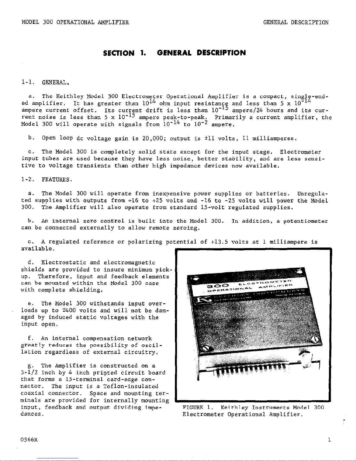
FIGURE 1. Keithley Instruments Model 300
Electrometer Operational Amplifier.
0566R 1
Page 4
GENERAL DESCRIPTION
MODEL 300 OPERATIONAL AMPLIFIER
l-3.
SPECIFICATIONS (Measured at 250C).
DC VOLTAGE GAIN,, OPEN LOOP:
Unloaded:
Greater than 20,000.
lOOO-ohm load: Greater than 12,000.
INPUT CHARACTERISTICS:
Resistance:
Greater than 1014 ohms.
Capacitance: Less than 10 picofarads.
Current Offset:
Less than 5 x LO-l4 ampere.
Drift: Less than lo-l5 ampere/24 hours.
Temperature Coefficient: Less than LO-15 ampere/OC.
Voltage Offset: Adjustable to zero.
Drift: Less than 500 microvolts/hour averaged over any 24-hour period after two-'
hour warm-up.*
Temperature Coefficient:
Less than 500 microvoltsf°C.*
Input Voltage Noise:
(0.1-10 cps): Less than 5 microvolts rms.
(10 cps-100 kc): Less than 5 millivolts rms.
Current Noise (0.1-10 cps): Less than 5 x LO-15 ampere peak-to-peak.
Overload Limit: ?400 volts.**
FREQUENCY CHARACTERISTICS:
Closed Loop Unity Gain, Small Signal: dc to 100 kc (-3db).
Slewing Rate: l'voltfmicrosecond minimum.
Gain Bandwidth Product: Greater than 150 kc.
Rolloff:
Approximately 6 db/octave.
OUTPUT:
Amplifier: rll volts at 11 milliamperes.
Reference Voltage:
+13.5 volts at 1 milliampere, regulated to *O.l% for 10% change in
input.
OPERATING TEMPERATURE: 0 to 5O'C.
CONNECTORS: Input: push-on coaxial receptacle, Amphenol 2175. All other connections:
15-terminal l/16 inch card-edge.
POWER REQUIREMENTS:
+16,to +25 volts unregulated, 35 milliamperes plus output current;
-16 to -25 volts unregulated,
8 milliamperes plus output current.
Note: Model 300 will also operate to specifications with standard 15-volt fO.l%
regulated power supplies.
DIMENSIONS, WEIGHT:
3-l/2 inches high x 4 inches wide x l-1/2 inches deep; net weight,
13 ounces.
ACCESSORIES SUPPLIED: Mating card-edge connector and Teflon-insulated coaxial input
connector with shield (chassis mounting).
*With 100% feedback this drift as a percent of full output is less than O.O05%/hour (or/OC,)
*with a LO5 ohm or greater feedback resistor without a shunting capacitor.
May require
several hours to recover to specified drift with severe overload.
2
0466R
Page 5
MODEL 300 OPERATIONAL AMPLIFIER GENERAL DESCRIPTION
l-4.
OPERATING MODES. The Model 300 is primarily a current amplifier.
It can be con-
veniently used in a number of operating modes:
linear current amplifier, logarithmic
current amplifier, current integrator and charge amplifier.
Section 2 describes these and
other operating modes for the Model 300.
1-5. ACCESSORIES (See Section 5.)
a.
Model 3011 Sheilded Switch can be used with the Model 300 where range switching is
required. The Switch is a 3-pole, &position, adjustable stop switch. The Model 3011 is
constructed for low leakage and to provide shielding for the components.
Refer to Section
5 for complete description.
b. Model 3012 Power Supply is designed to power 1,2 or 3 Model 300s.
The Model 3012
delivers positive and negative outputs between 16 and 25 volts, which fill all the power
requirements of'the Model 300. The Power Supply can be floated up
to
500 volts off
chassis ground.
c.
High megohm resistors are available for using'in the Model 300.
These resistors may
be mounted internally within the Amplifier or in the Model 3011 Shielded Switch. The
values available are:
1. Model R20-109 High Megohm Resistor; log ohms +3%.
2.
Model R20-lOlo High Megohm Resistor; 1010 ohms *3%
3:
Model R20-10'1 High Megohm Resistor; LOLL ohms ?3%.
4. Model R20-lQl* High Megohm Resistor; 101' ohms ?3%.
5.
Model R2O-10L3 High Megohm Resistor: 1013 ohms rlO%.
1-6. EQUIPMENT SHIPPED.
The Model 300 is shipped factory calibrated and connected as an
open loop opefational amplifier.
The built-in zero potentiometer (R112) is connected.
Feedback and input resistors are not included.
Shipped with the Model 300 is a mating 15
terminal card-edge connector, and Teflon insulated input connector with shielding hood.
06678
3
Page 6

OPERATION
MODEL 300 OPERATIONAL AMPLIFIER
Pin No.
Designation
Description Paragraph
Reference
INPUT INPUT
Teflon Insulated Coaxial Input
2-4
1
ALT. INPUT
May be used for large signals
2-4
2 GUARO
Used with ALT. INPUT
2-4
3 B
For remote mounting zero control
2-14
4
A
For remdte mounting zero control
2-14
5 -REF
Negative Reference Voltage (-14 volt output)
2-15
6 -16V to -25V
Negative Voltage Supply Input
2-3
7 ---
Not used
---
8 OUTPUT
Output
2-5
9
+REF
Positive Reference Voltage (+13.5 volt output)
2-15
10
+16V to t25V
Positive Voltage Supply Input
2-3
11 ---
Not used
---
12 ---
Not used
---
13
C
For remote mounting zero control
2-14
14 FEEDBACK
For fractional feedback
2-7
15 GROUND
Circuit Ground
2-4
TABLE 1. Model 300 Terminal Explanation.
Zero Adjust
(Rll2)
FIGURE 2.
Model 300 Terminal Designations. Kerer to Table 1 tar explanation or the
terminals.
4
0666R
Page 7
MODEL 300 OPERATIONAL AMPLIFIER
OPERATION
SECTION 2.
OPERATION
2-l.
TERMINALS.
The Model 300 input connector is a Teflon-insulated coaxial receptacle.
The 15-terminal card-edge is used for all other connections. The mating connector for
the 15-terminal card-edge is keyed to prevent improper insertion.
Refer to Figure 2 and
Table 1 for terminal identification and explanation.
2-2.
MOUNTING INSTRUCTIONS.
a. The Model 300 is designed for use in various measurement systems. It easily mounts
in a convenient location within a system.
b. To mount the Amplifier, attach the furnished card-edge mating connector (Keithley
Part No. CS-175-15) and shielded input mating connector (Keithley Part No. CS-179) with
the hooded shield (Keithley Part No. W-180) to a surface. Then plug the Model 300 into
the mating connectors. This mounting is acceptable for all positions except when the
mating connectors are above the Amplifier. Then, it may be necessary to use a bracket
or similar device to hold the Model 300.
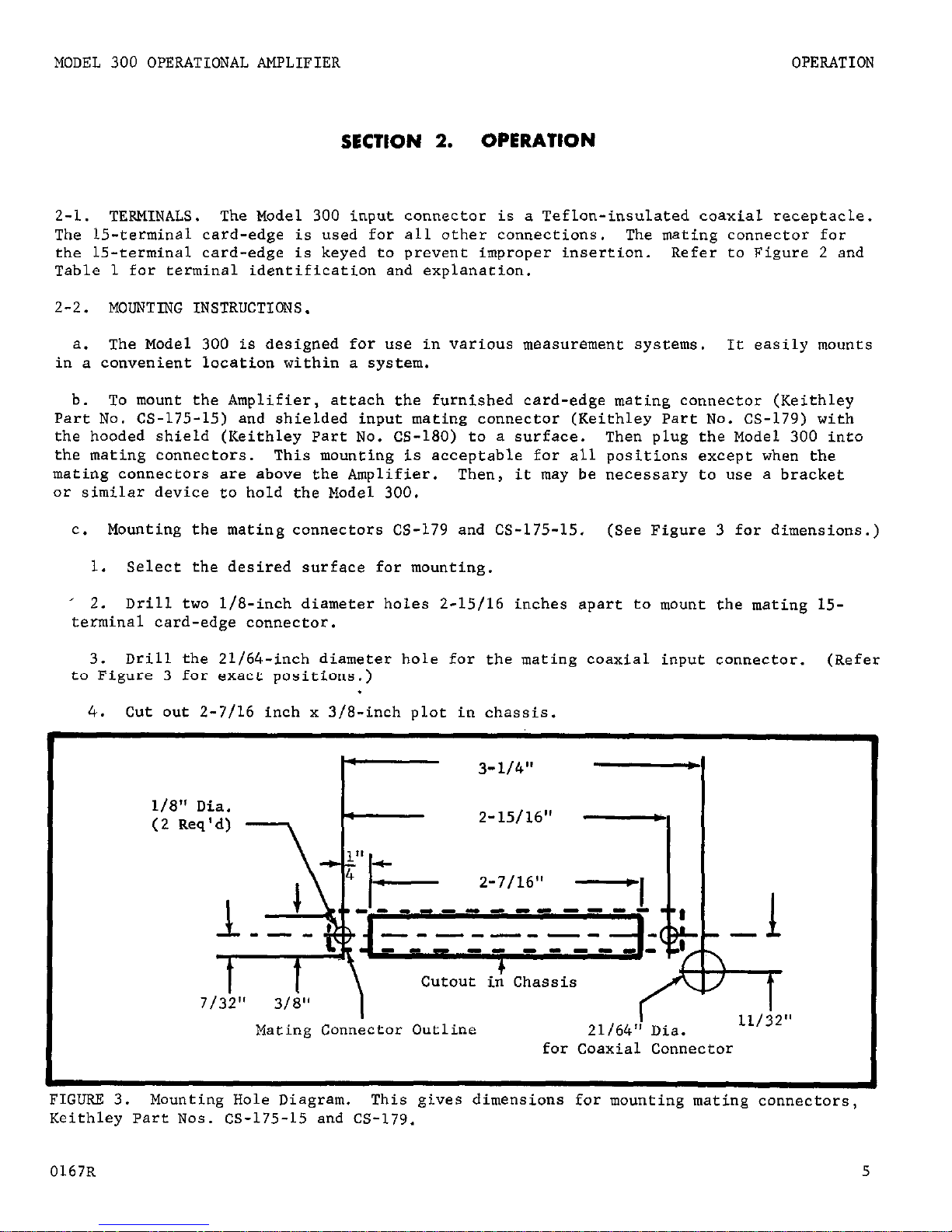
c. Mounting the mating connectors CS-179 and CS-175-15. (See Figure 3 for dimensions.)
1. Select the desired surface for mounting.
' 2. Drill two l/B-inch diameter holes 2-15/16 inches apart to mount the mating 15-
terminal card-edge connector.
3. Drill the 21/64,-inch diameter hole for the mating coaxial
input connector.
(Refer
to Figure 3 for exact positions.)
4,. Cut out 2-7116 inch x 3/B-inch plot in chassis.
r-
3-1/411
-
I
~~~e~~~~~~~~~,i
Mating Connector Outline
21/64" Dia.
for Coaxial Connector
FIGURE 3. Mounting Hole Diagram.
This gives dimensions for mounting
mating connectors,
Keithley Part Nos. CS-175-15 and CS-179.
0167R
5
Page 8
OPERATION
MODEL 300 OPERATIONAL AMPLIFIER
5.
Fasten the connectors in their proper positions.
6.
Attach the Model 300 to its mating connectors.
d.
The terminals of the mating connectors correspond exactly to,the terminals of the
Model 300 shown in Figure 2.
CS-179 is the mating connector for the INPUT Receptacle,
and CS-175-15 is the mating connector for the card-edge connector.
2-3. POWER SUPPLY.
a. The instantaneous value of the supply voltages must be between 16 and 25 volts.
For example, even a power supply whose value varies
from
16 to 25 volts can be used.
The
only exception is that a power supply with as low as a 15-volt output regulated to 0.1%
?
can be used. Connect the positive supply
to the +16V to +25V Terminal (pin 10,
Figure 2).
Connect the negative supply
to the -16V
to
-25V Terminal (pin 6, Fig-
ure 2).
b.
The Model 300 can operate from unregulated power supplies whose minimum instantaneous output falls below 16 volts.
However, the positive reference output must
be set below the normal 13.5 volts by ad-
justing the Regulator Adjust Potentiometer,
R209, (Figure 22). For example, to use a
power supply with a 15-volt minimum output,
set the positive reference output to 12.5
volts. Reducing the 13.5 volts of the
positive reference output reduces the max-
imum Amplifier output voltage by a 1:l
ratio; that is, reducing the reference
output one volt reduces the maximum output
voltage one volt.
Adjusting potentiometer
R209 is not necessary for 15-volt supplies
with 0.1% regulation.
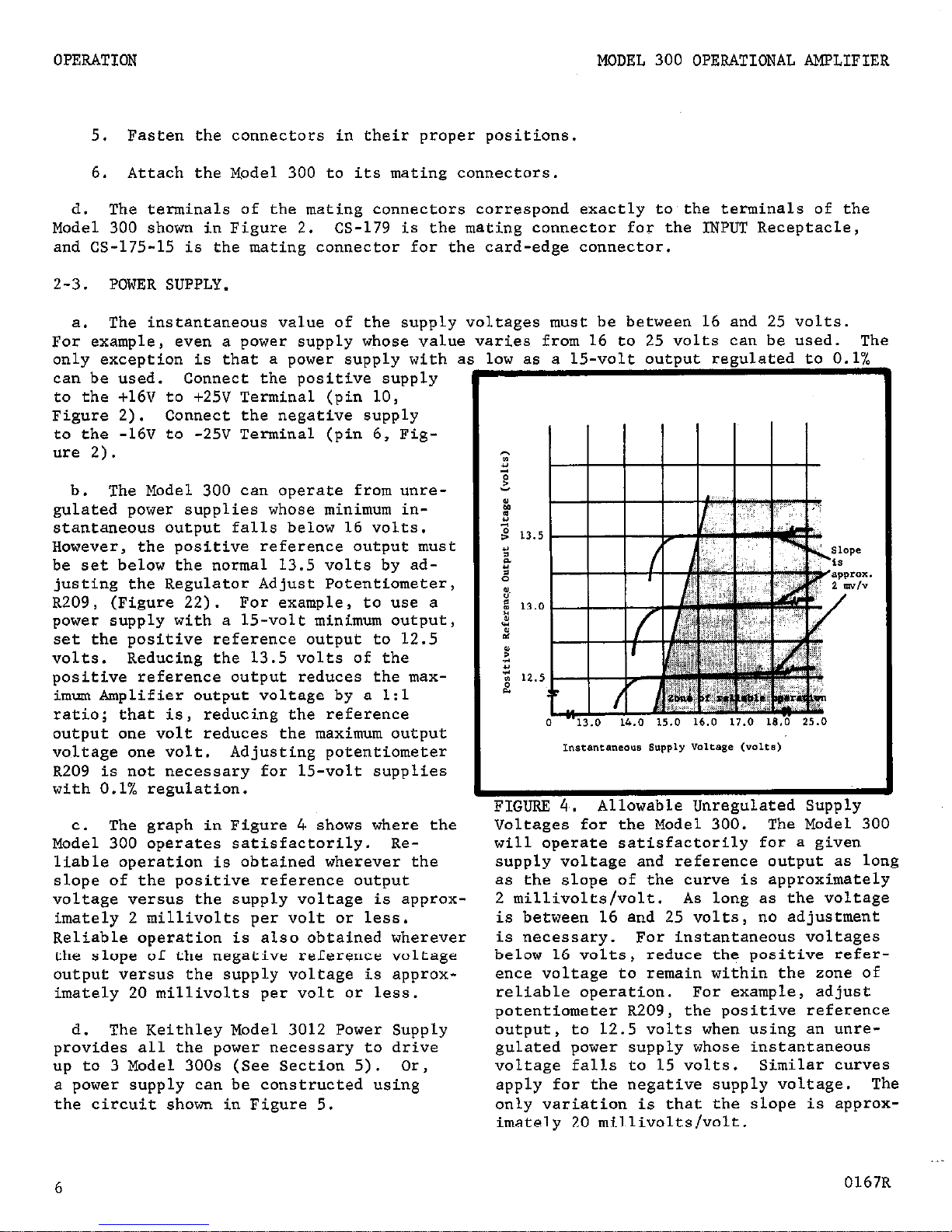
C.
The graph in Figure 4. shows where the
Model 300 operates satisfactorily. Re-
liable operation is obtained wherever the
slope of the positive reference output
voltage versus the supply voltage is approx-
imately 2 millivolts per volt or less.
Reliable operation is also obtained wherever
the slope of the negative reference voltage
output versus the supply voltage is approx-
imately 20 millivolts per volt or less.
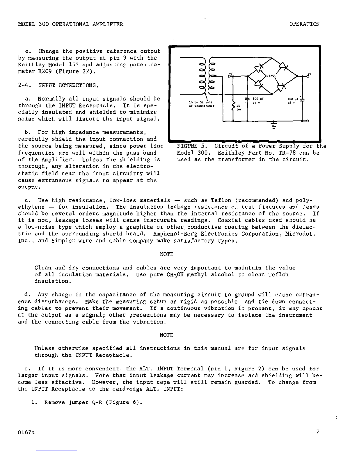
d.
The Keithley Model 3012 Power Supply
provides all the power necessary to drive
up to 3 Model 300s (See Section 5). Or,
a power supply can be constructed using
the circuit shown in Figure 5.
FIGURE 4,.
Allowable Unregulated Supply
Voltages for the Model 300. The Model 300
will operate satisfactorily for a given
supply voltage and reference output as long
as the slope of the curve is approximately
2 millivolts/volt. As long as the voltage
is between 16 and 25 volts, no adjustment
is necessary. For instantaneous voltages
below 16 volts,
reduce the positive refer-
ence voltage to remain within the zone of
reliable operation.
For example, adjust
potentiometer R209,
the positive reference
output,
to 12.5 volts when using an unregulated power supply whose instantaneous
voltage falls to 15 volts.
Similar curves
apply for the negative supply voltage. The
only variation is that the slope is approx-
imately 20 millivolts/volt.
6
0167R
Page 9
MODEL 300 OPERATIONAL AMPLIFIER
OPERATION
e. Change the positive reference output
by measuring the output at pin 9 with the
Keithley Model 153 and adjusting potentiometer R209 (Figure 22).
2-4.. INPUT CONNECTIONS.
a. Normally all input signals should be
through the INPUT Receptacle.
It is specially insulated and shielded to minimize
noise which will distort the input signal.
b. For high impedance measurements,
carefully shield the input connection and
the source being measured, since power line
frequencies are well within the pass band
of the Amplifier. Unless the shielding is
thorough, any alteration in the electrostatic field near the input circuitry will
cause extraneous signals to appear at the
output.
:
Circuit of a Power Supply for the
Model 300. Keithley Part No. TR-78 can be
used as the transformer in the circuit.
c. Use high resistance, low-loss materials - such as Teflon (recommended) and polyethylene - for insulation. The insulation leakage resistance of test fixtures and leads
should be several orders magnitude higher than the internal resistance of the source. If
it is not, leakage losses will cause inaccurate readings. Coaxial cables used should be
a low-noise type which employ a graphite or other, conductive coating between the dielectric and the surrounding shield braid.
Amphenol-Borg Electronics Corporation, Microdot,
Inc., and Simplex Wire and Cable Company make satisfactory types.
NOTE
Clean and dry connections and cables are very important to maintain the value
of all insulation materials. Use pure CH30H methyl alcohol to clean Teflon
insulation.
d. Any change in the capacitance of the measuring circuit to ground will cause extran-
eous disturbances.
Make the measuring setup as rigid as possible, and tie'down connect-
ing cables to prevent their movement.
If a continuous vibration is present, it may appear
at the output as a signal;
other precautions may be necessary to isolate the instrument
and the connecting cable from the vibration.
NOTE
Unless otherwise specified all instructions in this manual are for input signals
through the INPUT Receptacle.
e. If it .is more convenient,
larger input signals.
the ALT. INPUT Terminal (pin 1, Figure 2) can be used for
Note that input leakage current may increase and shielding will be-
come less effective.
However,
the input tape will still remain guarded.
To change from
the INPUT Receptacle to the card-edge ALT. INPUT:
1.
Remove jumper Q-R (Figure 6).
0167R
7
Page 10
OPERATION
MODEL 300 OPERATIONAL AMPLIFIER
2.
Connect terminal R to hole P (Figure 6) located,at the end of the ALT. INPUT tape.
NOTE
Do not use the GUARD Terminal for GROUND, even though GUARD and GROUND are shown
connected in the schematic diagram.
Severe ground loops may result.
f.
The Model 300's input overload limit of f400 volts is for LO5 ohms or greater feed-
back impedance.
This ensures that the output stage will not be damaged by large transient
feedback currents.
Any combination of resistance and capacitance with 105 ohms minimum
feedback impedance is acceptable.
However, when using a capacitor, the impedance is de-
pendent upon frequency. As frequency increases, impedance is reduced:
1
zc = 2nfC
equation 1
where ZC is the impedance in ohms;
f is the frequency in cps;
c is the capacitance in farads.
Therefore,
if spikes or steps are present in the overload signal, the frequency increases
greatly and the impedance decreases.
In this situation the feedback impedance is less
than 105 ohms.
2-5. OUTPUT CONNECTIONS.
a. The output voltage is through the OUTPUT Terminal (pin 8, Figure 2). Almost any
means of looking at the output voltage can be employed as long as the load on the output
is not less than 1000 ohms.
Excessive capacitance loading at the output (usually greater than 1000 picofarads) will cause oscillation.
This can usually be stabilized through com-
pensation elsewhere in the circuit (paragraph 2-13).
b.
Output overload protection is provided for the Model 300. Thus a temporary direct
short to ground at the output is harmless.
However, extended periods of shorted output,
with the Model 300 in a saturated or near saturated state, may damage the Amplifier.
2-6.
MODES OF OPERATION.
a.
The Model 300 Operational Amplifier can be used in many different modes of operation
through simple adjustment of its circuitry. Paragraphs 2-7 through 2-12 describe the construction and use of several of the modes.
Refer to Table 2 for the paragraph describing
each operating mode.
b.
The Model 300 can be used in these different operating modes through the mounting
of various elements in the feedback and input circuits.
The components can be mounted
within the Model 300 case with complete shielding. To connect multiple feedback or input
elements, use the Model 301lShielded Switch. The mode of operation is determined by the
type of component used and where it is placed in the circuit.
8
.~
0666R
Page 11
MODEL 300 OPERATIONAL AMPLIFIER
OPERATION
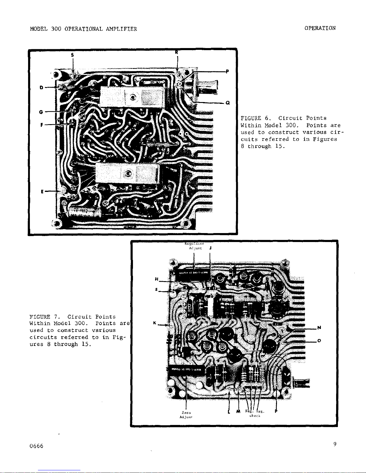
FIGURE 6.
Circuit Points
Within Model 300.
Points are
used to construct various circuits referred to in Figures
8 through 15.
I
aegulaCar
Ad,“It J
FIGURE 7.
Circuit Points
Within Model 300. Points ax
used to construct various
circuits referred to in Figures 8 through 15.
HE-
K-
0666
Page 12
OPERATION
MODEL 300 OPERATIONAL AMPLIFIER
Operating Mode
Paragraph
Linear Current Amplifier Without Fractional Feedback
2-7
Linear Current Amplifier With Fractional Feedback
2-7
Logarithmic Current Amplifier
2-8
Current Integrator or Charge Amplifier
2-9
Impedance Matching Amplifier 2-10
Voltage Amplifier Without Fractional Feedback 2-11
Voltage Amplifier With Fractional Feedback 2-11
Other Circuits 2-12
TABLE 2.
Model 300 Operating Modes and Paragraph Describing the Modes.
c.
Figures 8 through 15 illustrate the various modes of operation.
The lettered ter-
minals in these figures refer to the lettered points in Figures 6 and 7.
Ref.er to the
figures to connect jumpers and to mount elements.
d.
Adjusting the Zero Adjust Potentiometer, R112 (Figure 7), sets the output to zero
voltage for no input signal. There is a hole in the cover (Figure 2) enabling this adjustment to be made without removing the cover. Refer to paragraph 2-14 for other adjustments.
2-7. LINEAR CURRENT AMPLIFIER (Figures 8 and 9).
a.
Placing a resistor in the feedback loop converts the Model 300 to a linear current
amplifier.
The output voltage depends on the magnitude of the feedback resistor and the
input current.
"out = -Iink
where Vout is the output voltage in volts;
Ii,, is the input current in amperes;
Rfb is the feedback resistance in ohms.
equation 2
For a given iriput current the output voltage can be chosen by selecting the, feedback resistor, Rfb,
By using the largest possible feedback resistor (such as the high megohm
resistor accessories), V,ut can be as much as fll volts.
Keeping V,,t as large as pos-
sible results in a better signal-to-noise ratio at the output.
b.
Using fractional feedback increases the output voltage gain although drift and noise
also increase. Fractional feedback is useful for amplifying different current levels
while using only one high megohm resistor in the feedback loop.
Be careful when handling the high megohm resistors,
Hold these resistors by
the ends of the leads; do not touch the glass.
Contamination will change the
resistor value,
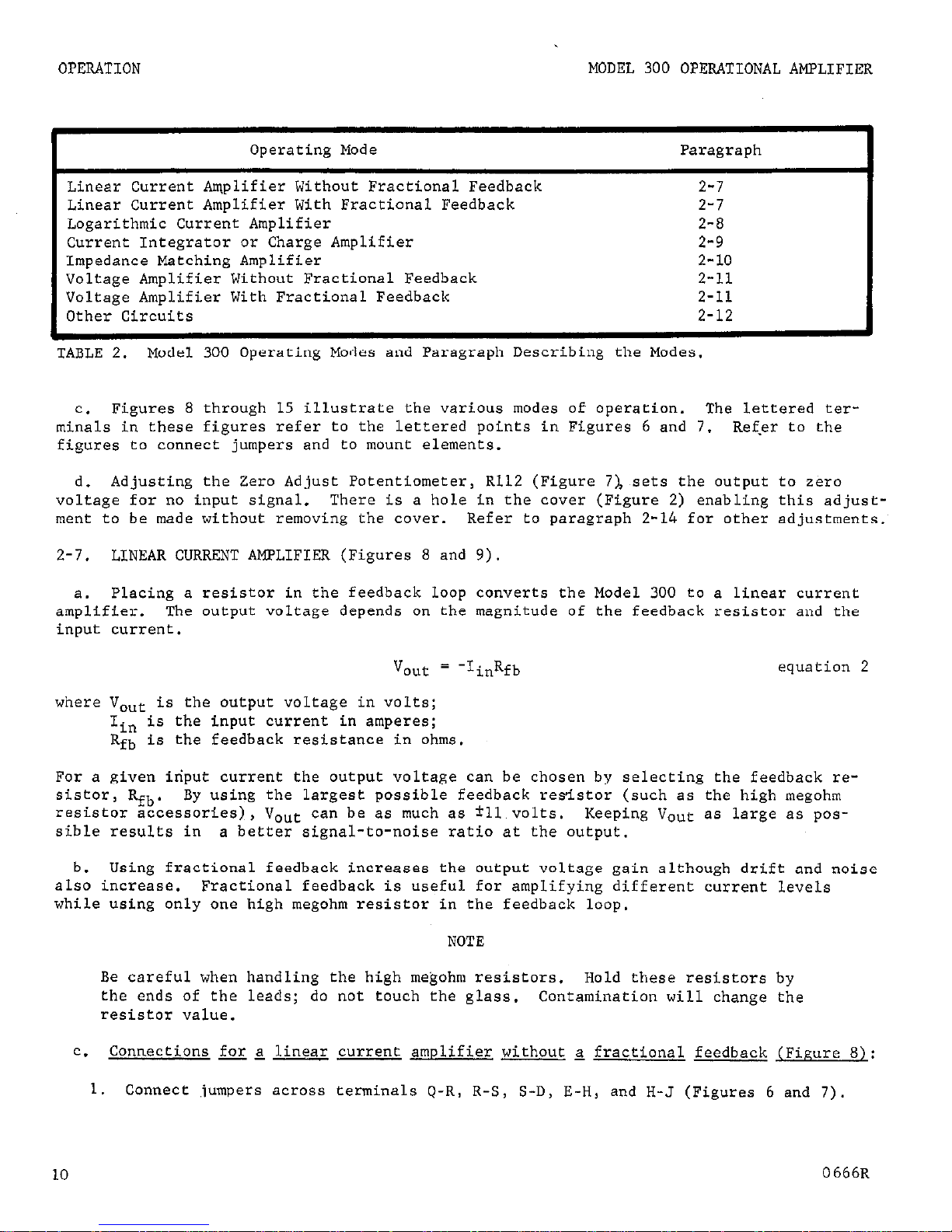
=.
Connections for a linear current amplifier without a fractional feedback (Figure 8):
1. Connect ,jumpers across terminals Q-R, R-S,
S-D, E-H, and H-J (Figures 6 and 7)
10
0666R
Page 13
MODEL 300 OPERATIONAL AMPLIFIER
OPERATION
FIGURE 8.
Linear Current Amplifier With-
out Fractional Feedback.
FIGURE 9. Linear Current Amplifier With
FractionaL Feedback.
NOTE
The Model 300 is shipped from the factory in the linear current amplifier mode
minus the element in the feedback loop.
Therefore it is shipped with jumpers
connected across terminals Q-R, R-S, S-D, E-H and H-J.
2. Remove any element of jumper from across E-K (Figure 7).
3. Mount the feedback resistor, Rfb,
in the feedback loop across terminals D and E.
4. The output voltage for the Model 30.0 as a linear current amplifier without a
fractional feedback is given by equation 2.
d. Connections for a linear current amplifier with a fractional feedback (Figure 9):
---
--
1.
Connect jumpers across terminals Q-R, R-S, S-D and E-H (Figures 6 and 7).
2. Mount the feedback resistor, Rfb,
in the feedback loop across terminals D and E
3. Mount fractional resistors Rl
and R2 (Figure 9) across terminals J-H and H-K
respectively.
4. The output voltage for the Model 300 as a linear current ampiifier with fractional
feedback is
v
out
= -IinRfb
equation 3
where V,ut is the output voltage in volts;
Iin is the.input current in amperes;
Rfb is the feedback resistance in ohms;
Rl and R2 are the divider resistances in ohms.
NOTE
The current through fractional resistors R1
that through the feedback resistor, Rfb,
and R2 should be much greater than
to maintain proper amplification. Also,
R1 + R2 should be greater than 1 kilohm so as not to overload the output.
0766R
11
Page 14
OPERATION
MODEL 300 OPERATIONAL AMPLIFIER
Feedback
Resistor
1olOn
1olCn
1012Sl
101*sl
% Feedback
100%
10%
100%
10%
Output Voltage
10 v 10 v
10 v
10 v
Input current
10-9 amp 10-10 amp
10-11 amp
10-12
amp
Resolution
10-11 imp 10-12 amp
10-13
amp
10-14 amp
Current Offset,
% of output
0.005%
0.05%
0.5%
5%
Drift/Hour
% of output
0.005%
0.05% 0.005%
0.05%
Ovserved Rise Time
10 msec
20 msec
200 msec
300 msec
,
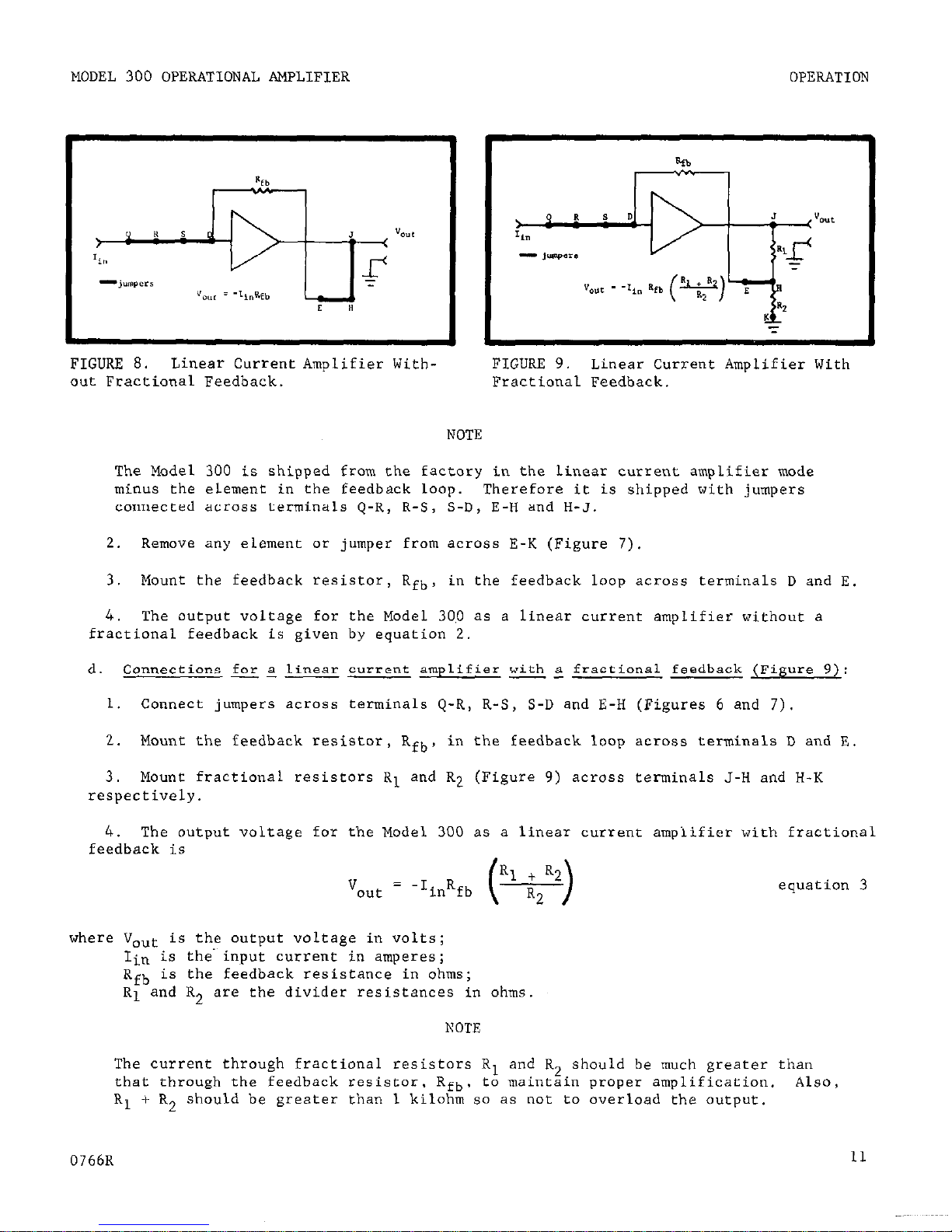
TABLE 3. Typical Performance Values for the Model 300 Used as a Linear Current Amplifier.
Offset, drift and rise time are affected by the circuit used, but the above table shows
some of the Model 300's capabilities.
"% Feedback" refers to fractional feedback equation
3;
100% is
with
no fractional feedback.
e.
To mount the divider outside the Model 300, do the following:
---
--- --
1. Connect jumpers across terminals Q-R, R-S,
S-D and E-H (Figures 6 and 7).
2.
Remove all elements from.J-H and H-K.
3. Mount the feedback resistor, Rfb,
in the feedback loop across terminals D and E.
Connect FEEDBACK (pin 14, Figure 2) or terminal H to the center of an external
dizider. (T
erminal H is connected to FEEDBACK).
5. Connect one end of the divider to OUTPUT (pin 8, Figure 2) or terminal J.
(Ter-
minal 3 is connected to OUTPUT).
(See NOTE paragraph 2-7d).
2-a.
LOGARITHMIC CURRENT AMPLIFIER (Figure 10).
a. Silicon diodes or transistors in the feedback loop make the Model 300 a logarithmic
current amplifier.
The log characteristic of the element used determines the amplifier
performance. lN459 diodes and silicon transistors usually provide 7 to 9 accurate decades.
The leakage current of the element should be at least two magnitudes less than the current
being measured.
b. The circuit for the logarithmic current amplifier is shown in Figure 10.
This cir-
cuit uses a single diode and is for positive currents.
The output voltage is:
V
out
= -A log Iin
equation 4
where Vout is the output voltage in volts;
Iin is the input current in amperes;
A is a positive constant, dependent upon the characteristic of the diode.
12
0766R
Page 15

MODEL 300 OPERATIONAL AMPLIFIER
OPERATION
Amplify negative currents by reversing the diode polarity. Measure both positive and
negative polarities by mounting the diodes in parallel and in opposite directions in the
feedback circuit.
Altering the circuit changes the value of A.
1. Adding diodes in series increases A. Therefore, Vout increases for a given input
current.
This approach reduces the effect of drift, since the drift becomes a smaller
percentage of the output voltage.
2. Fractional feedback increases A and thus increases the output voltage, Vout.
However, this method increases the drift proportionally as the output is increased.
The proportionality constant, A, is increased by the amount (Rl + R2)/R2. Rl and R2
are the fractional feedback resistors as shown in Figure 9.
For construction of the
fractional feedback, see paragraphs 2-7d and 2-7e.
c.
To zero the output,
a variable voltage between the log element in the feedback loop
and the output is required. This variable voltage can be achieved by use of a biasing
network in the feedback loop.
The biasing network should consist of a potentiometer in
parallel with a battery.
Mount this network externally in series between the log element
and the output.
The log element is available at the FEEDBACK Terminal (pin 14, Figure 2).
Connect the Model 300 as in paragraph 2-8e except that any element or jumper should be
removed from H-J. Adjusting the potentiometer will select the required voltage drop needed to zero the output.
The only requirement of the biasing network is that the current
around this network must be much greater than the current through the diode in the feed-
back loop.
d. Silicon transistors are also useful as log elements and they have better response
speed.>\ Using the basic circuit of Figure 10, positive currents can be amplified by using
an NPN transistor in the feedback loop. Negative currents can be amplified by using a
PNP transistor in the feedback loop. In both operations the base of the transistor can
either be connected to the collector of the transistor or to ground. Connect the collector
to the input and the emitter to the output.
NOTE
For further information send for the Keithley Product Note “Using the Model 300
Operational Amplifier as a Logarithmic Current Amplifier.”
e. Connections for the Model 300 as a logarithmic current amplifier (Figure 10):
------
1. Connect jumpers across terminals Q-R, R-S,
S-D, E-H and H-J (Figures 6 and 7).
2. Remove any element or jumper from H-K
3. Mount the logarithmic elements in the feedback circuit as needed to amplify posi-
tive or negative input currents.
Figure 10 shows a diode mounted for positive currents,
4. The output voltage for the Model 300 as a logarithmic current amplifier is given
by equation 4.
g:For more information on Silicon transistors used as log elements see “A Circuit With
Logarithmic Transfer Response Over 9 Decades”, by J. F. Gibbons and H. S. Horn, IEEE
Traxactions on Circuit Theory, September, 1964.
0766R
13
Page 16

OPERATION
MODEL 300 OPERATIONAL AMPLIFIER
IGURE 10.
Logarithmic Current Amplifier
Diode shown for positive currents
FIGURE 11.
Current Integrator or Charge
Amplifier.
z-,9.
CURRENT INTEGRATOR OR CHARGE AMPLIFIER (Figure 11).
a.
The current integrator mode and the charge amplifier mode use capacitors in the
feedback circuit.
These two modes are essentially the same,
the only difference being in
their purpose.
b.
Connections for the Model 300 as a current integrator or charge amplifier (Fiwre 11):
1.
connect jumpers across terminals Q-R,
R-S, S-D, E-H, and H-J (Figures 6 and 7).
2. mount a capacitor in the feedback c.ircuif between terminals D and E.
3.
The output voltage for the
as a current integrator is
v
out
Iin dt
equation 5
where V,,t is the output voltage in volts;
Iin is the input current in amperes;
Cfb is the feedback capacitance in farads.
4.
The output voltage for the Model 300 as a charge amplifier is
V
OUt = p = Iint
Cfb Cfb
equation 6
where Vout
is the output voltage in volts;
Q is the applied charge in coulombs;
Cfb is the feedback capacitance in farads;
Iin is the input current in amperes;
t is the time in seconds.
NOTE
An output divider network can be mounted as described in paragraphs 2-7d and 2-7e.
14
0666R
Page 17

MODEL 300 OPERATIONAL AMPLIFIER
OPERATION
FIGURE 12. Impedance Matching Unity-Gain
Amplifier.
-- __.- - .^ _ . .._
FLti”KE LJ.
mpedance Matcnrng AmpLitier
with Divided Output.
Z-10.
IMPEDANCE MATCHING AMPLIFIER (Figures 12 and 13).
a.
The Model 300 is an excellent impedance matching amplifier. This mode requires no
elements in the feedback circuit. Use the Amplifier in this mode either for unity gain
or to obtain voltage gain. Achieve voltage gain using an internal or external dividing
network on the output (Figure 13). Use the Model 300 as an impedance matching amplifier
only with a floating power supply or a floating signal source from LO millivolts to LL
volts.
Insulate the Model 300 input connector in this mode.
b. Exercise care in grounding when using the Model 300 as an impedance matching ampli-
fier .
1.
For the unity-gain amplifier (Figure 12): if the Low side of the signal source is
grounded,
then the high side of the output is grounded. Therefore, the power supply
must be floating if the signal source is not.
2.
For an amplifier with voltage gain (Figure 13):
if the signal source is floating,
the power supply need not be floating. If the signal source is grounded, both the power
supply and the output monitoring deivce must float.
3.
The Keithley Model 3012 Power Supply meets the floating requirements of the Model
.300 (See Section 5). Also available for insulated mechanical support of the Models 300
or 3012 is the Model 3013 Insulated Hold-Down Bracket.
c. Connections for the Model 300 as an impedance matchinp amplifier (Figure 12):
------
1. Connect a power supply to the Model 300 (see paragraph Z-3).
2. Connect jumpers across terminals Q-R,
R-S and S-D (Figures 6 and 7).
3. Remove all elements from D-E, H-K and H-J.
4. Apply the signal between INPUT and OUTPUT. Monitor the output between OUTPUT and
GROUND.
0667R
15
Page 18

OPERATION MODEL 300 OPERATIONAL AMPLIFIER
5.
The output voltage for the Model 300 as an impedance matching amplifier is
v
out
= Vi* equation 7
where Vout
is the output voltage in volts;
"in
is the input voltage in volt?,.
d.
Connections for the Model 300 as an impedance matching amplifier with a. divided
-- ---- --
output (Figure 13):
1.
Connect a power supply to the Model 300 (see paragraph 2-3).
2.
Connect jumpers across terminals Q-R, R-S, S-D and E-H (Figures 6 and 7).
3.
Remove all elements from D-E.
4..
Mount,divider resistors across J-H and H-K.
5.
Apply the signal between INPUT and FEEDBACK.
Monitor the output between OUTPUT
and GROUND.
6.
The output voltage for the Model 300 as an impedance matching amplifier with a
divided outwt is
equation 8
where Vout is the output voltage in volts;
Vi,, is the input voltage, in volts;
Rl and R2 are the divider resistances in ohms.
NOTE
The sum of the resistances of Rl and R2 must be at least 1 kilohm. The current
through Rl and R2 must be much greater than the grid current of the Amplifier.
IGURE 14.. Voltage Amplifier Without E
IGURE 15. Voltage Amplifier With Frac-
tional Feedback.
16
tional Feedback.
0167R
Page 19

MODEL 300 OPERATIONAL AMPLIFIER
OPERATION
Z-11.
VOLTAGE AMPLIFIER (Figures 14, and 15).
a. As a voltage amplifier,
the Model 300 uses an input resistor in addition to a feed-
back resistor.
The ratio of the feedback and input resistors determines the voltage gain
(equation 9).
Use an input resistor whose value is more than 100 times greater than the
source resistance to minimize loading the source.
The input resistance of the Model 300
in this mode is now the value of the input resistor, Rin.
b.
Connections for the Model 300 as a voltage amplifier without 2 divided feedback
----
(Figure 14~):
1. Connect jumpers across terminals Q-R,
S-D, E-H and H-J (Figures 6 and 7).
2.
Mount feedback resistor, Rfb,
across terminals D-E in the feedback circuit.
3.
Mount an input resistor, Rin, across terminals R-S.
4..
The output voltage for the Model 300 as a voltage amplifier without a divided
feedback is
v
out
equation 9
where V,ut
is the output voltage in volts;
is the input voltage in volts;
is the feedback resistance in ohms;
in is the input resistance in ohms.
c.
Connections for the Model 300 as a voltage amplifier with fractional feedback
------
iFigure 15):
1. Connect jumpers across terminals Q-R, S-D and E-H (Figures 6 and 7).
2.
Mount feedback resistor, Rfb, across terminals D-E in the feedback circuit.
3.
Mount input resistor, Rin, across terminals R-S.
4,. Mount divider resistors, Rl and R2,
xtoss terminals J-H and H-K respectively
5.
The output voltage for the Model 300 as a voltage amplifier with fractional feed-
back is
V
out = -"in ( z)(R1 z:)
where V,ut is the output voltage in volts;
Vin is the input voltage in volts;
Rfb is the feedback resistance in ohms;
Rin is the input resistance in ohms;
Rl and R2 are the divider resistances in ohms.
equation 10
The current through fractional resistors Rl and R2
should be much greater than
that through the feedback resistor, R
fb '
to maintain proper amplification.
Also, Rl + R2 should be greater than kllohm so as to not overload the output.
0167R
17
Page 20

OPERATION MODEL 300 OPERATIONAL AMPLIFIER
2-12.
OTHER MODES OF OPERATION.
The preceding paragraphs describe several modes in which
the Model 300 can be used. These modes use basically the same circuit construction. The
main difference is the feedback element. Alterations permit many more uses with the Model
300. Some of these possibilities are as voltage integrator, voltage differentiator,
current differentiator, adder,
open loop voltage comparator, and others.
2-13.
STABILITY,.FRGQUENCY RESPONSE, AND OSCILLATION.
a. A logarithmic plot of an amplifier's dc voltage gain versus the frequency is known
as a Bode plot.
When the slope of the Bode plot of an amplifier rolls off at 6 dbloctave,
the amplifier is unconditionally stable. An amplifier is conditionally stable when the
roll off is between 6 db/octave and 12 db/octave.
An amplifier is unstable and, there-
fore, will oscillate when its Bode plot rolls off at greater than 12 db/octave.
b. The Keithley Model 300 is a very stable amplifier. The Bode plot of the Model 300
approaches the ideal 6 db/octave through use of an internal roll-off network that stabilizes the amplifier. If the Model 300 did not have a roll-off network, its Bode plot
would be similar to the many segmented dotted curve shown in Figure lb.
This curve is
completely random at&uncontrollable. HOWeVer,
the Model 300's internal roll-off network
cuts off the high frequency response (moves the slope line to the left). Thus,
operation
on the natural roll-off curve (dotted line) will never occur.
However, due to the many
variables present, this 6 db/octave may not be present in every application.
C. The frequency bandwidth of the Model 300 is narrowed,
thus improving its stability.
The gain-bandwidth product for a stabilized amplifier is 150 Kc, while for the unstabili-
zed amplifier it is about 1 MC. HOWeVer, a minor adjustment in the roll-off network can
increase the frequency response in the Model 300. In general, increasing the resistance
and decreasing the capacitance of the roll-off network (resistor R103, Figure 22, and
capacitor C102, Figure 23) will increase the frequency response, although it will also
decrease the stability of the amplifier.
d. Additional stability results from placing a very small damping capacitor (3 to 10
picofarads) across the feedback element.
This can be useful for stopping oscillation,
reducing overshoot of square waves and reducing noise. However,
this also has the effect
of reducing frequency response and increasing rise time.
6
dbloctave
Frequency
1 Mcps
IGURE lb. Bode Plot for Model 300.
1
A
B
'lc.URc. L,. nemore I",OUnLe(L ‘era L"ncrOI.
Letters refer to terminals in Figure 2.
18
0167R
Page 21

MODEL 300 OPERATIONAL AMPLIFIER
OPERATION
I
FINE
A
COURSE
A
B
iGURE 18.
Remote Mounted Coarse and Fine
Zero Control.
Letters refer to terminals
in Figure 2.
A
C
Rl12 INTERNAL
COURSE
d
PANEL
FINE
10K
B
10K
IGURE 19. Internal Coarse Zero and Remo
Mounted Fine Zero. Letters refer to termin-
als in Figure 2.
R112 is already connected
within the Model 300.
2-14..
REMOTE ZERO CONTROL.
a.
The Zero Adjust Potentiometer, R112, is accessible without removing the cover. A
simple modification
permits
finer zero control or external zeroing.
This allows remotely
locating a zero control in a more convenient place or improving zeroing resolution.
EX-
ternal zeroing is possible with several circuits:
substituting an external control for the
internal control; using the external control for fine zeroing and the internal control
for coarse zeroing; using external fine and coarse controls and disconnecting the inter-
nal control; or some other arbitrary configuration.
b.
The external control can be a IO-turn, 5-kilohm wirewound potentiometer manufactured
by several companies.
If greater resolution is desired, use a potentiometer with more
turns.
c.
External zero control connections (Figure 17).
1.
Disconnect jumpers F-G and L-M (Figures 6 and 7) to remove potentiometer RL12
(Figure 22) from the circuit.
2.
Connect the external potentiometer to terminals A, B and C (Figure 2).
Refer to
Figure 17.
d.
External fine and coarse zero control connections (Figure 18).
--
1.
Disconnect jumpers F-G and L-M (Figures b and 7) to remove potentiometer RlL2
(Figure 22) from the circuit.
2.
Connect a coarse potentiometer and a resistor in series between pins A and B (Fig-
ure 2) of the Model 300 card-edge connector. This potentiometer will become the coarse
zero control.
3.
Connect a fine zero potentiometer as shown in Figure 18.
OL67R
19
Page 22

OPERATION MODEL 300 OPERATIONAL AMPLIFIER
4,. The total resistance between A and B should be about 5 kilohms.
e. External fine and internal coarse zero control connections (
--
Figure 20).
1. Connect a potentiometer in series with a resistor of at least 10 kilohms between
terminals C and A or between terminals C and B, as in Figure 19.
2. Do not disconnect jumpers F-G and L-M.
2-15.
CONNECTIONS AND USE OF REFERENCE VOLTAGES.
a. The reference voltages are useful for polarizing voltages for ion chambers, for grid
current buckout and for log diode biasing, In normal operation the reference output voltages available are +13.5 volts and approximately -14 volts.
The
amount
of additional cur-
rent that can be drawn from the + REF Terminal depends on the amplifier output current, the
ambient temperature and the supply voltages.
Around 8 milliamperes can be drawn from the
+ REF under th’e worst conditions; i.e.,
a full output load, power supply voltage around
25 volts and an operating temperature at 50%. The negative regulator supplies about 1
milliampere at these conditions.
More current can be supplied under more favorable con-
ditions.
b.
Access to Reference Voltages:
1. The +13.5 volt reference is available through the + REF Terminal (pin 9, Figure 2).
It. is connected at all times and is protected from overloads.
A temporary direct short
to ground will not cause damage.
2.
The negative voltage reference, whose nominal value is approximately -14 volts,
is independent of the negative supply voltage and load.
The negative regulator output
is not connected to the Negative Supply terminal (pin 6, Figure 2).
It may be connected
by attaching a jumper from 0 to N, (Figure 6).
NOTE
Overload protection is not provided on the negative reference voltage.
Any over-
load could damage the pass transistor, Q203.
3. Paragraph 2-3 and Figure 4, show the response of reference outputs to changes in
power supplies.
20
0167R
Page 23

MODEL 300 OPERATIONAL AMPLIFIER
CIRCUIT DESCRIPTION
SECTION 3.
CIRCUIT DESCRIPTION
3-1. GENERAL.
a. The Keithley Model 300 Operational Amplifier uses a pair of high impedance balanced
electrometer tubes at its input, followed by solid-state differential amplifier stages.
Positive and negative power supply regulators enable the Model 300 to operate from a var-
iety of inexpensive power supplies. Input and feedback elements are easily mounted within the case to provide shielding for the complete circuit, or they may be externally
mounted.
b. By using different components - such
as resistors, diodes, capacitors - in the
feedback circuit,, the Model 300 can operate
in various modes: linear current amplifier,
logarithmic current amplifier, current in-
tegrator and so forth.
NOTE
Circuit designations refer to
schematic diagram 19558D in Section 6.
I5 10 -.,I"
3-2. ELECTROMETER INPUT. Two balanced
electrometer tubes, VlOl and V102, are at
b
the Amplifier input.
The input signal is
FIGURE 20.
Model 300 Block Diagram.
The
applied to the grid of V101. The tube fila-
circuit for the Model 300 is within the
ments are operated in parallel from the re- shaded portion.
gulated +13.5 volt supply through dropping
resistors Rl04 and RlO6.
Resistor RlOl pro-
tects the control grid of the active tube,
VlOl, from excessive grid current due to ex-
cessive overload. The input capacitor, ClOl, is a high-frequency bypass.
The control
grid of V102 is returned to ground.
3-3. SOLID STATE DIFFERENTIAL AMPLIFIER.
a. An emitter follower stage, transistors QlOl and Q102, matches the relatively high
output impedance of the input stage to the low input impedance of the next differential
amplifier stage, formed by transistors 4103 and Q104.
This latter stage drives a second
differential amplifier stage,
transistors Q105 and Q106.
b. The final ~differential stage drives the complimentary pair output stage, transistors
Q107 and Q108. Resistors Rll9 and R120 eliminate any crossover distortion.
Resistor R121
and diode DlOl are provided as an overload limit when the output voltage is negative.
Positive output overload protection is achieved by overload limiting the positive regulator.
c.
The zero adjust.control. potentiometer Rl12,
adjusts the dc voltage of the screen
grid for tube V102.
The screen grids of the tubes are returned, in effect, to the emit-
ters of transistors 4103 and 4104.
This connection stabilizes the electrometer plate
potential and tube operating points.
0566~ 21
Page 24

CIRCUIT DESCRIPTION
MODEL 300 OPERATIONAL AMPLIFIER
3-4. POSITIVE POWER SUPPLY REGULATOR.
a.
This circuit regulates the +16 to +25 volt unregulated power supply input to the
Model 300.
It provides an output adjusted to +13.5 volts for the electrometer tube fila-
ments and for all amplifier stages.
b.
To obtain a stable, accurate voltage, the output of the series transistor, 9203, is
regulated by comparing a sample voltage from the output dividers, resistors R208 to R210,
to the zener reference diode, D205.
If a voltage difference exists, it is amplified by a
differential amplifier, transistors Q206 and Q207. The signal is further amplified by
transistor Q204 and applied to transistor Q201.
This transistor is an emitter follower
whose function is to increase the current gain of the series transistor, Q'2.03, with which
it forms a Darlington pair.
c.
Capacitors C201 and C202 prevent high-frequency oscillations. The series resistor,
R204, and diodes D201 to D203 provide overload protection. If excessive current is drawn,
the voltage drop across resistor R204 increases. This forward biases the diodes which
prevent the Darlington pair from supplying additional current.
3-5. NEGATIVE POWER SUPPLY REGULATOR.
a. This circuit regulates the -16 to -25 volt unregulated power supply input to the
Model 300. It provides an output of approximately -14 volts to the last three amplifier
stages.
Since these stages are less cnitical in the Amplifier operation, the voltage
supplied to them is not as well regulated as the positive voltage.
b.
The series transistor, 9202, is controlled by sampling the variation of its output
and comparing it to the regulated +13.5 volts. The difference is amplified by trans,istor
4205 and applied to the base of transistor Q202. There is no overload protection.
22
Page 25

MODEL 300 OPERATIONAL AMPLIFIER
MAINTENANCE
SECTION 4.
MAINTENANCE
4-1. GENERAL.
This Section contains the maintenance, troubleshooting and calibrating procedures for the Model 300. Follow these procedures as closely as possible to maintain reliable operation for the Amplifier.
4-2. MAINTENANCE SCHEDULE. The Model 300 requires no periodic maintenance beyond the nor-
mal care required of high-quality electronic equipment. The most useful check is to make
sure the positive reference output (pin 9,
Figure 2) is +13.5 volts ?l%.
4-3. PARTS REPLACEMENT.
a.
The Replaceable Parts List in Section 6 describes the electrical components of the
Model 300.
Replace components only as necessary. Use only reliable replacements which
meet the specifications.
b.
The electrometer tubes, VlOl and V102, are specially matched and aged; order these
only from Keithley Instruments, Inc., or its representative.
In normal use, they should
not need replacement before 10,000 hours of operation. They can be checked only by replacement. Standard 5886 tubes could be used in an emergency, but the drift, noise and
grid current specifications may not be met.
NOTE
When replacing the electrometer tubes,' do not touch the glass base where the
leads converge. Increased leakage will result from any contamination.
c.
Transistor pairs QlOl, Q102 and 9103, 4104 are matched for dc current gain (hFB).
Order only from Keithley Instruments, Inc., or its representative.
Replace only as pairs.
d.
Transistor 4105, QlO6 and 4206
are selected for minimum current gain (hFE) of 50.
Order only from Keithley Instruments, Inc., or its representative.
Instrument
Use
Keithley Instruments Model 153 Microvolt-
~~11 detector to check amplifier stages
Ammeter; 10 (iv to 1000 v, 200 M'2 input re-
sistance, ?l% accuracy, float 2500 " off
ground
Keithley Instruments Model 610B Electro-
meter; lo-14 to 0.3 ampere, 1 mv to 100 v
ranges; il% accuracy, 1014 0 input resistance
Check currents and circuit
Voltage Supply; minimum 10 to 30-volt output,
positive and negative; O.Ol-volt
steps; minimum 35 milliampere output
Source for checking regulators
TABLE 4. Equipment Recommended for Model 300 Troubleshooting.
Use these or their equiva-
lent.
0866R
23
Page 26

MAINTENANCE MODEL 300 OPERATIONAL AMPLIFIER
NOTE
The
accuracy.of the Amplifier depends almost exclusively on the accuracy of the
associated circuitry.
Impedance elements and output monitoring devices determine this. Therefore, use extreme care in selecting and handling these items
to minimize leakage and noise.
4-4. TROUBLESHOOTING.
30::
The following procedures are for repairing troubles which might occur in the Model
Use the procedures outlined and use only specified replacement parts.
Table 4 lists
equipment recommended for troubleshooting. If the problem cannot be readily located or
repaired, Keithley Instruments, Inc., can service the Amplifier at its complete service
facilities.
Contact your nearest representative.
b.
Table 5 contains the more common troubles which might occur.
If the repairs indi-
cated do not clear up the trouble, find the difficulty through a circuit-by-circuit check,
The schematic diagram contains typical voltages at various points. A properly operating
Difficulty Probable Cause
Solution
:xcessive zero drift Electrometer tubes defective
Check VlOl and V102; replace if faulty
Regulator(s) defective
Check per paragraph 4-5
Zxcessive grid current Excessive humidity or defective
Check VlOl and V102; re-
electrometer tubes
place if faulty
Jnable to zero output
Amplifier not functioning
Check per paragraph 4-6
Electrometer tubes have aged and
Check VlOl and V102; re-
drifted
place if faulty
Jumpers F-G and L-M may be dis-
Connect F-G and L-M
connected (Figur&b and 7)
:ll volt output not Faulty regulator operation
Check par paragraph 4-5
obtainable
Output overloaded
Remove excessive load
<eference output vol- Regulator out of adjustment Adjust potentiometer RZO'
:age not correct
tegulators do not
iunction
:xcrssive 60 cps in
>utput
Supply voltages may be dropping
Increase supply voltage
below 1~6-volt minimum (paragraph 2-3)
Defective regulator circuits
Check per paragraph 4-5
Regulators not functioning
Cheek per paragraph 4-5
TABLE 5. Model 300 Troubleshooting.
See paragraph 4-3 for checking electrometer tubes.
Also refer to paragraph 4-4 for step-by-step procedures.
24
05661~
Page 27

MODEL 300 OPERATIONAL AMPLIFIER
MAINTENANCE
Amplifier will have these values ilO%/,.
Voltages were measured with the Model 153.
Refer
to the Circuit Description in Section 3 to find the more critical components and to determine their function in the circuit.
4-5. TROUBLESHOOTING POSITIVE AND NEGATIVE POWER SUPPLY REGULATORS.
a. Check both the positive and negative power supplies to the Model 300 to make sure
they provide between 16 and 25 volts.
Check the input power supply currents with the
Model 153 or 610B: with no output load,
the positive power supply should be approximately
-1-35 milliamperes and the negative power supply approximately -8 milliamperes.
Higher in-
put currents indicate one or more transistor has shorted in the regulator or the amplifier.
b.
Check the positive regulator output by measuring for 113.5 volts "1% with the Model
153 at the positive reference output (pin 9, Figure 2). Internally check the negative
regulator output by measuring for -14 volts f5% with the Model 153 at the Negative Regu-
lator Check (Figure 7).
c. Check the regulation of the positive regulator by varying the input voltage. CO*-
nect the Voltage Supply to the positive supply (pin 10, Figure 2). Use the Model 153 to
monitor the output at pin 9, Figure 2.
If the regulator is operating satisfactorily, the
positive reference voltage will change no more than 2 millivolts for every l-volt change
to the input between +16 and +25 volts.
d. Check the regulation of the negative regulator similarly. Connect the Voltage sup-
ply to the negative supply (pin 6, Figure 2).
Use the Model 153 to monitor the signal at the
Negative Regulator Check (Figure 7).
If the regulator is operating satisfactorily, the
Model 153 will show less than 20 millivolts change for every l-volt change to the input
between -16 and -25 volts.
e.
If either regulator is not operating (zero regulation), the series transistor is
probably shorted and should be replaced.
For the positive regulator, replace Q203 (Fig-
ure 23). For the negative regulator, replace Q202 (Figure 23).
f. If the positive regulator has poor regulation, use the following procedure:
1. Remove the positive power supply from the Amplifier.
2. Apply +13.5 volts to the iREF Terminal (pin 9, Figure 2).
3.
Measure the voltage at the wiper of potentiometer R209 (Figure 22). The voltage
should be about 9 volts. If 113.5 volts is present, then resistor RZLO (Figure 22) is
either faulty or it is not connected.
If 0 volt is present then resistor ~208 (Figure
2,2) is either faulty or it is not connected.
If neither +13.5 volts nor 0 volts is pre-
sent and if the voltage is not about 9 volts, then potentiometer R209 is faulty.
4. If the voltage is about 9 volts,
adjust potentiometer R209 a few turns to make
sure that this voltage varies.
Then check the base voltage of transistor Q206 (Figure
23). This voltage should be between 8.55 volts and 9.45 volts.
If it is not, then
either resistor R205 (Figure 22) or diode D204 (Figure '23) is faulty. Next, check the
collector of transistor Q206 to see if the voltage here varies when potentiometer R209
is adjusted.
If it does not vary,
then either transistors Q206 or Q207 or both are faulty.
5. Finally, check the voltage at the collector of transistor Q204 (Figure 23) and
make sure that there is a response to adjusting R209. If there is no response at the
0866R
25
Page 28

MAINTENANCE
MODEL 300 OPERATIONAL AMPLIFIER
collector,
then transistor Q204 is faulty.
If there is a response, then either Q201
or Q203 is faulty.
For the negative regulator, repair is easiest by replacing transistors 4202 and Q205
(Figure 23).
4-6. TROUBLESHOOTING THE AMPLIFIER
a.
Disconnect all feedback elements and
short the input to ground. This allows
each stage of the amplifier to be individually checked.
-7
rted Dot
b. Connect the Model 153 between the
plates (Figure 21) of VlOl and V102 (Figure
24).
Adjust the zero potentiometer, R112
(Figure
i2),
for null. If null cannot be
FIGURE 21. Base Connections for Electroreached, check the tubes, the zero control meter Tube.
circuit, and transistors QlOl and Q102
(Figure 23).
Check the transistors by re-
placing them and adjusting for null again.
If null is now reached, replace the transis-
tor pair with a new pair.
Check the next stage by connecting the Model 153 acr0s.s the emitters of transis-
to:: QlOl and Q102 (Figure 23) and adjusting the 'zero potentiometer, Rll2 (Figure 22),
for null. If null is not reached, check this stage and the base circuit of the next
stage.
Check the base circuit by removing transistors Q103 and Q104 (Figure 23) and
again adjusting for null. If null is now reached, replace Q103 and Q104 with a new pair.
d.
Check the next stage by connecting the Model 153 across the collectors of Q103 and
Q104 (Figure 23) and adjusting for null. If null is not reached, check this stage and
check for shorts in the circuit of QlO5 and Q106 (Figure 23).
e. Check transistors QlO5 and Q106 by measuring the potential of the collector of QlO5
with respect to ground. Note that as adjusting potentiometer R112 (Figure 22) carries
the other stages through null,
the voltage at the collector should swing from at least -11
volts to at least +ll volts.
If this does not occur, disconnect the output stage by re-
moving transistor Q107 and resistor R119. Now repeat adjusting potentiometer Rl12. If
the collector of QlO5 still does not swing 211 volts, replace transistor QlO5 or Q106 or
both.
If transistors QlO5 and QlO6 were operating properly,
then the defect is in the
output stage and replace transistor Q107 or QlOS (Figure 23) or both.
4-7. CALIBRATION.
All calibration adjustments are made at the factory and no periodic
adjustments are required under normal use.
Checking for proper operation as given in
paragraphs 4-5 and 4-6 will calibrate the Model 300.
26
0666R
Page 29

MODEL 300 OPERATIONAL AMPLIFIER
FIGURE 23. Component Locations on
PC-110, Model 300.
For resistors
see Figure 22.
For components on
other side of PC-110, see Figure 24
FIGURE 22.
Resistor Locations on
PC-110, HO
de1 300.
locations,
For component
see Figure 23.
For com-
ponents on
other side of PC-110,
see Figure
24.
MAINTENANCE
0666
Page 30

MAINTENANCE
MODEL 300 OPERATIONAL AMPLUTE
FIGURE 24.
Component Locations on PC-110, Model 300.
For components on other side of PC-110, see Figures 22
and 23.
28
0666
Page 31

MODEL 300 OPERATIONAL AMPLIFIER
SECTION 5.
ACCESSORIES
ACCESSORIES
5-l. MODEL 3012 POWER SUPPLY
a. General.
1. The Keithley Model 3012 is a line-operated unregulated power supply.
It is a
dual supply with positive and negative outputs of 20 volts ?25%. The Power Supply can
be operated from a line source of 105-125 volts or 210-250 volts.
2. The Model 3012 is for powering the
Keithley Model 300 Operational Amplifier.
Up to three Model 300s can be driven by
the Power Supply without sacrificing per-
formance. It can be floated at up to 500
volts off chassis ground. The Power Supply
is a completely self-contained unit and
has nearly the same exterior appearance
as the Model 300.
3. The Model 3013 Insulated Hold-Down
Bracket provides rigid mechanical support
for the Model 3012 or Model 300.
The
Bracket is insulated for use with the
Model 300 during floating operation.
b.
Specifications.
OUTPUT: As required for 1, 2 or 3 Keithley
Model 300 Electrometer Operational Ampli-
fiers.
FIGURE 25.
Keithley Model 3012 Power Supp
ISOLATION :
ground;
Circguit ground to chassis
over 10
ohms shunted by less
than 50 picofarads. Circuit ground may be floated up to 500 volts off chassis ground,
CONNECTOR: 15 terminal l/16-inch card-edge.
POWER REQUIRED:
105-125 volts or 210-250 volts, 50-60 cps, 10 watts.
OPERATING TEMPERATURE: With one or two Model 300 Amplifiers; 50°C Maximum ambient.
With three Model 300 Amplifiers; 4,O'C Maximum ambient.
DIMENSIONS, WEIGHT:
3-l/2 inches high x 4~ inches wide x l-1/2 inches deep; net weight,
17 ounces.
ACCESSORIES SUPPLIED: Mating card-edge connector.
ACCESSORIES AVAILABLE:
Model 3013 Insulated Hold-Down Bracket: Provides rigid support for Models 300 or 3012.
0167~
29
Page 32

ACCESSORIES MODEL 300 OPERATIONAL AMPLIFIER
c. Operation.
1.
The Model 3012 has a 15-terminal card-edge connector, which is part of the pc
board, that is used for all connections.
A mating card-edge connector is supplied with
the Model 3012.
The mating connector is keyed so that the Model 3012 cannot be reverse
connected to its mating connector.
NOTE
The Model 3012 can power up to three Model 300 Amplifiers. If more than three
Model 300's are used with one Model 3012, then the Power Supply will provide
less than the required voltages to each Model 300.
2. To secure the Model 3012 in operating position, first mount the input mating con-
'nectar on an appropriate surface. See Figure 3 for mounting hole diagram.
The mounting
procedure for the Model 3012 is the same as for the Model 300 except that the 3012 does
not have a coaxial connector.
Check the power line voltage and frequency. Next, wire
the power line to the Model 3012 mating connector.
The method of wiring the power line
to the Model 3012 mating connector terminals is different for the 105-125 volt source
than it is for the 210-250 volt source.
Refer to Figure 26 for wiring instructions.
a.
For a 105-125 volt source,
connect one lead from the power cord to terminals
1 and 2, and connect the other lead to terminals 3 and 4,. See Figure 26a.
b.
For a 210-250 volt source,
connect one lead to terminal 1, one lead to terminal
4 and connect terminals 2 and 3 together.
Se'e Figure 26b.
3.
Connect the +16 to +25V Terminal on the Model 3012 mating connector to the +16 to
+25V Terminal on the Model 300 mating connector.
Connect the -16 to -25V Terminal on
the Model 3012 mating connector to the -16 to -25V Terminal on the Model 300 mating
connector.
Connect the GROUND Terminal on the Model 3012 to the GROUND Terminal on the
Model 300.
4..
In floating operation,
connect the Model 3012 CASE to the circuit ground of the
system.
In normal
operation,
connect the Model 3012 CASE and GROUND Terminals to the
GLJRE 26.
Diagrams for Wiring the Power Line to the Model 3012 Connector. Diagram 26a
for a 105-125 volt source and diagram 26b is for a 210-250 volt source.
30
0667R
Page 33

MODEL 300 OPERATIONAL AMPLIFIER
ACCESSORIES
NOTE
In floating operation one Model 3012 should not be used to power more than one
Model 300 unless they have a common ground. -
5.
Plug the Model 3012 into its mating connector.
d.
Circuit Description.
The Model 3012 Power Supply has a dual-primary transformer
which is connected in parallel from a 105-125 volt ac power source and in series from a
210-250 volt ac power source.
This is a result of the wiring from the ac power cord to
the primary transformer.
The transformer secondary winding is center tapped for dual full-
wave rectification by a diode bridge configuration, DlOl through D104.
The positive out-
put of the diode bridge is filtered by capacitor ClOl,
and the negative supply is filtered
by capacitor ~102.
A bleeder resistor, R101, improves load regulation for the negative
output.
e.
Maintenance.
1. The Keithley Model 3012 Power Supply has no adjustments or controls.
All calibra-
tion adjustments are made at the factory and no periodic adjustments are required under
normal "se.
2.
No trouble should occur under normal use.
However,
if problems arise, tnen "se
the following procedures:
a.
If there is no output from the Model 3012, check for a blown fuse.
b.
If there is a low or high voltage output of the Model 3012, chech the line voltage
and make sure that the power cord is wired to the mating connector correctly,
5-2. MODEL 3011 SHIELDED SWITCH.
a. General.
The Keithley Model 3011
Shielded Switch is a 3-pole, &?-position
adjustable stop switch.
The Model 3011 is
constructed for low leakage and to provide
shielding for the components.
One deck,
which accommodates the feedback or input
resistors,
is Teflon insulated with greater
than 1014 ohms insulation ,resistance between terminals and ground.
The switch
contains two additional decks for these or
other components,
such as divider or damp-
ing networks.
Three Teflon-insulated bnc
connectors provide electrical access to
the Model 3011.
b.
Mounting (Figure 28).
1.
For best results mount high megohm
resistors in the four clockwise positions
The hole in the Teflon insulated deck (4.)
has Teflon insulated bushings in these
four positions.
The extra deck (2) can be
FIGURE 27.
Model 3011 Shielded Switch.
0667R
31
Page 34

ACCESSORIES MODEL 300 OPERATIONAL AMPLIFIER
less than l/4 inch less than l/4 inch
-I I- -I I-
6 6
I 4
4
1 1 .., .,
;I_' .., .,
;I_'
d d
I
I I
10
10 5 / /
5
11 11 I I I I
9 8 9 8
I 3
4 4
1
FIGURE 28. Model 3011 Shielded FIGURE 28. Model 3011 Shielded Switch Switch Diagram. Diagram.
used for mounting divider or damping components.
i.
The panel (9) should be less than l/4 inch thick and should have holes drilled
into it for the bushing and lug (Figure 29). The panel,
in conjunction with the bush-
ing and lug, physically stabilizes the Model 3011 Switch.
3.
Insert the short lug (6) into the desired hole in the front plate (12) of the
Switch.
This adjusts switch stopping. Insert the larger lug over the bushing against
the first lug.
This second lug should face opposite the first lug.
4. .
Insert the Switch into its shield. Make sure the bushing (5) and the larger lug
(6) are fitted into the proper holes on the front panel of the shield.
5.
Insert the bushing and lug into the panel (9).
6.
Secure the Switch and panel with the nut and lockwasher (10).
7.
Attach the knob (11) to the Switch.
c. Installation and Hook-up for Switching Feedback (Figure 30).
1.
One INPUT Receptacle on the Model 3011 is used as the input to the system.
The
other INPUT Receptacle is used as the input to the Model 300 INPUT Receptacle.
Use bnc
connectors and coaxial cables with the Model 3011 INPUT Terminals.
2.
Connect the Model 3011 FEEDBACK Terminal to the Model 300 OUTPUT Terminal.
Single
unshielded cable may be used for the Feedback. Use bnc connectors with the FEEDBACK
Terminal.
32
0167R
Page 35

MODEL 300 OPERATIONAL AMPLIFIER
Item
(See Figure 28)
Description
1
Rear Cover (No. 19487B)
2
Extra Deck
3 Component Mounting Decks
4,
Teflon Insulated Deck
5 Threaded Bushing
6
Lugs (2 required)
7
Component positions
8 Shield (No. 194,02A)
9 Panel (not furnished with
Switch)
10
Nut and lockwasher
11
Knob (No. 16338A)
12
Front Plate
ABLE 6.
Model 3011 Callout and Descrip-
tion
ACCESSORIES
.390 in.
Dia.
A
-- ---_
--.---_
.094 in.
Dia.
--
1:
-_
1
38 in.
-
I
'IGUW 29. Required Dimensions of Model
,011 Front Panel (used to physically sta-
ilize the Switch).
3.
To use the Model 3011 for switching feedback elements:
a.
Inside the Model 3011 Switch, connect a wire between the two INPUT Terminals
and the solder lug connected to the wiper on the Teflon insulated deck (4,, Figure 28).
b. Connect a second wire from the FEEDBACK Terminal to the wiper on one of the
rear component mounting decks (Figure 30).
NOTE
Make sure that the input wires,
unless they are Teflon insulated, do not come
in contact with any part of the switch except the necessary points of connection.
0167R
33
Page 36

ACCESSORIES
MODEL 300 OPERATIONAL AMPLIFIER
INPUT
t3z-E
INSULATED
DECK
I
r INPUT
J FEEDBACK
8
-===I
MODEL
300
L < OUTPUT
SWITCH
SHIELD
/
FIGURE 30.
Model 3011 Installation and Hook-up Diagram.
34
0167R
Page 37

MODEL 300 OPERATIONAL AMPLIFIER
REPLACEABLE PARTS
SECTION 6.
REPLACEABLE PARTS
6-l. REPLACEABLE PARTS LIST. The Replaceable Parts List describes the components of the
Model 300 and its accessories.
The List gives the circuit designation, the part descrip-
tion,
a suggested manufacturer, the manufacturer's part number and, the Keithley Part Num-
ber. The last column indicates the figure picturing the part.
The name and address of
the manufacturers listed in the "Mfg. Code" column are in Table 8.
6-2. HOW TO ORDER PARTS.
a.
For parts orders,
include the instrument's model and serial number, the Keithley
Part Number, the circuit designation and a description of the part.
All structual parts
are those parts coded for Keithley manufacture (80164) must be ordered through Keithley
Instruments, Inc. or its representatives. In ordering a part not listed in the Replaceable Parts List, completely describe the part, its function and its location.
b. Order parts through your nearest Keithley representative or the Sales Service De-
partment, Keithley Instruments, Inc.
amp
CerD
camp
DCb
ETB
f
Fig.
c
3
tfg.
ampere
MtF
MY
Ceramic Disc
Composition
n
Deposited Carbon
P
Electrolytic Tubular
)J
farad
"
Figure
w
kilo (103) ww
wwvar
Megohms (106)
Manufacturer
TABLE 7.
Abbreviations and Symbols
Metal Film
Mylar
ohm
pica (10-12)
micro (lo-$
volt
watt
Wirewound
Wirewound Variable
0167R
35
Page 38

REPLACEABLE PARTS
MODEL 300 OPERATIONAL AMPLIFIER
(Refer
to
MODEL 300 REPLACEABLE PARTS LIST
Schematic Diagram 195581) for circuit
designation)
CAPACITORS
Circuit
Mfg.
Mfg. Keithley
Fig.
Desig. Value Rating
Type
Code
Part No.
Part No.
Ref.
Cl01
22 pf 600 v
CerD 72982
ED-22
c22-22P 24
Cl02
k.068 IJ.f 100 v
MY
88480
3FR 683-1E
Cl46-.068M 23
c201
330 pf 600 v
CerD 72982
ED-330
C22-330P 23
c202
125 pf 15 v
ETB 56289
TE 1162
C3-125M 24
DIODES
Circuit
Desig.
Type
Number
Mfg.
Code
Keithley
Part No.
Fig.
Ref.
DlOl
D201
D202
D203
D204
0205
Circuit
Desig.
Silicon lN645
01295
Silicon lN645
01295
Silicon lN645
01295
Silicon lN645
01295
Silicon lN645
01295
Zener lN936
04713
MISCELLANEOUS PARTS
Description
Mfg.
Code
RF-14
23
RF-14
23
RF-14
23
RF-14
23
RF-14
23
DZ-5 23
Keithley
Part No.
Fig.
Ref.
JlOl Coaxial Receptacle (Mfg. No. FXR 2175
02660 CS-178
24
--_
(F)Plug, Mate of JlOl (Mfg. No. FXR 30775)
02660 cs-179
-_
---
(F)Hooded Shield for CS-179 (Mfg. No. FXR2273 02660
CS-180
-_
---
(F)Connector, 15 pin card-edge (Mfg. No.
PSC4SS15-12)
03612 cs-175-15 --
VlOl
Electrometer tube
80164
EV-5886-5
24
v102
Electrometer tube
80164 EV-5886-5
24
RESISTORS
Circuit
Mfg.
Mfg.
Keithley
Fig.
Desig. Value Rating
Type
Code
Part No. Part No.
Ref.
RlOl 10 Ma
lO%, l/2 w Comp
01121 EB
Rl-1OM
24
R102 150 kfl
l%, l/2 w MtF 07716
CEC R94-150K 22
R103 "68 R
lo%, l/2 w camp 01121 EB
R1-$<68 22
R104
91 n
3%, 1 w
ww
02985 400TS-1W R81-91
22
R105 150 n
l%, l/2 w MtF 07716
CEC
R94-150K 22
:cNominal value, factory set
(F)Furnished accessory
36
0167R
Page 39

MODEL 300 OPERATIONAL AMPLIFIER
REPLACEABLE PARTS
RESISTORS (Con't)
Circuit
Mfg.
Mfg.
Keithley
Fig.
Desig.
Value Rating
TYPO
Code Part No.
Part No.
Ref.
Rl06
R107
Rl08
R109
RllO
500 *
10 kn
100 kn
10 kn
100 kn
ww
02985 400TS-1W R81-500
22
camp
01121 EB Rl-1OK
22
Comp
01121 EB Rl-100K
22
Comp 01121 EB
Rl-1OK
22
Comp 01121 EB
Rl-100K
22
Rlll
R112
R113
R114
R115
8.2 kfi
5 kn
2.1 kn
2.7 kn
33 kn
camp
01121
wwvar
80294
camp
01121
Comp
01121
Comp
01121
EB Rl-8.2K
3067P-l-502 RP39-5K
Rl-2.7K EB
EB
EB
Rl-2.7K
Rl-33K
22
22
22
22
22
R116
R117
Rll8
R119
R120
8.2 kn
680 n
22 kn
39 n
220 kfl
camp 01121 EB Rl-8.2K
22
Comp 01121 CB R76-680
22
Comp
01121 EB Rl-22K
22
Comp
01121
EB Rl-39
22
Comp 01121 EB Rl-220K
22
R121
10 12
Comp 01121 EB Rl-10
2.2
R201
R202
R203
R204
R205
15 kn
10 kn
22 kn
6.8 n
I&
Camp
01121 CB R76-15K
22
Comp
01121
CB
R76-10K
22
Comp 01121 CB
R76-22K 22
Comp
01121
CB R76-6.8 22
Comp
01121
CB R76-1K
22
R206
R207
R208
R209
R210
R211
R212
3.3 kn
4.7 m
3.3 kn
2hl
8.2 m
3%, 1 w
10x, l/2 w
lo%, l/2 w
lO%, l/2 w
lO%, 112 w
lO%, l/2 w
lO%, l/2 w
lO%, l/2 w
lO%, l/2 w
lO%, l/2 w
lO%, 112 w
lO%, l/4 w
lO%, l/2 w
lO%, l/2 w
lO%, l/2 w
lO%, l/2 w
lO%, l/4 w
lO%, l/4 w
lO%, l/4 w
lO%, l/4 w
lO%, l/4 w
lO%, l/4 w
lO%, l/4 w
lO%, l/4 w
lO%, l/2 w
lO%, l/4 w
l%, l/2 w
l%, l/2 w
Comp
01121
CB R76-3.3K
Comp
01121 CB
R76-4.7K
camp 01121 CB
R76-3.3K
wwvar
80294 3067-l-502
RP39-ZK
Comp
01121
CB
R76-8.2K
9kn
8.6 kfl
DCb 79727
CFE-15
R12-9K
DCb
79727 CFE-15
RLZ-8.6K
22
22
22
22
22
24
22
TRANSISTORS
Circuit
Mfg.
Keithley
Fig.
Desig.
Number Code Part No. Ref.
QlOl A1380 80164 ~~~~18548A 23
Q102 A1380 80164 >'*:18548A 23
Q103 A1380 80164
%?‘18548A
23
Q104 A1380 80164 "~*18548A 23
Q105 517638 07263 TG-33 23
>+ QlOl, Q102 and 4103, 4104 are matched pairs. Order only from Keithley Instruments,
Inc.
0167R 37
Page 40

REPLACEABLE PARTS
MODEL 300 OPERATIONAL AMPLIFIER
TRANSISTORS (Cont'd)
Circuit
Des&.
Number
Mfg.
Code
Keithley
Part No.
Fig.
Ref.
Q106
Q107
QlO8
9201
Q202
Q203
Q204,
Q205
S17638
07263
2N2430
734,45
2N2706
734.4,5
2N1605
93332
2N2431
734,4~5
2N2270
02735
A1380
734'4.5
517638
07263
TG-33
23
TG-36
23
TG-35 23
TG-22 23
TG-37
23
TG-25
23
TG-32
23
TG-33
23
~206
Q207
A1380
A1380
734.4.5
734.4,5
MODEL 3012 REPLACEABLE PARTS LIST
(Refer to Schematic Diagram 20351B for circuit designations)
Circuit
Desig.
Description
Mfg.
code
Keithley
Part No.
Cl01
Cl02
DlOl
D102
D103
D104.
FlOl
F102
JlOl
_--
RlOl
Capacitor, Electrolytic aluminum, 400 vf
4,O " (Mfg. No. C4,37AR/G4,00)
Capacitor, Electrolytic aluminum, 100 (if
734,4,5
734,4,5
40 " (Mfg. No. C4,37AR/G100)
Diode, Silicon, lN3253
Diode, Silicon, lN3253
Diode, Silicon, lN3253
Diode, Silicon, lN3253
02735 RF-20
02735 RF-20
02735
RF-20
02735 RF-20
Fuse,
l/8 amp, 8AG (Mfg. No. 361.125)
FUSE!, l/8 amp, 8AG (Mfg. NO. 361.125)
75915
FU-5
75915 FU-5
connector,
part of pc board
---
Connector, furnished mating 15 pin card-edge
80164,
Resistor, Composition, 2.2 kfl, lo%, 1 w
(Mfg. No. GB)
01121
TlOl
Transformer
80164~
TR-97
C150-4,OOM
Cl50-100M
---
cs-175-4,
RZ-2.2K
38
0167R
Page 41

MODEL 300 OPERATIONAL AMPLIFIER REPLACEABLE PARTS
01121 Allen-Bradley Corp. 07716 International Resistance Co.
Milwaukee, Wis. Burlington, Iowa
01295 Texas Instruments, Inc.
13050 Potter co.
Semi Conductor-Components Division
Wesson, Miss.
Dallas, Texas
56289 Sprague Electric Co.
02660 Amphenol-Borg Electronics Corp. North Adams, Mass.
Broadview, Chicago, Illinois
72982 Erie Technological Products, Inc.
02735 Radio Corp. of America Erie, Pa.
Commercial Receiving Tube and
Semiconductor Division 734.4.5 Amperex Electronic Co. Division of
Somerville, N. J.
North American Philips Co., Inc.
Hicksville, N. Y.
02985 Tepro Electric Corp.
Rochester, N. Y.
79727 Continental-Wirt Electronics Corp.
Philadelphia, Pa.
03612 Burndy Corp.
Lynwood, Calif.
80164, Keithley Instruments, Inc.
Cleveland, Ohio
04,713 Motorola, Inc.
Semiconductor Products Division 80294. Bourns Laboratories, Inc.
Phoenix, Arizona Riverside, Calif.
07263 Fairchild Camera and Instrument Corp. 93332 Sylvania Electric Products, Inc.
Semiconductor Division Semiconductor Products Division
Mountain View, Calif. Woburn, Mass.
TABLE 8. Code List of Suggested i@nufacturers. (Based on Federal supply
code
for Manu-
facturers, Cataloging Handbook H&l.)
0167~
39
Page 42

b-f-----
Page 43

--Y
--1
r---
--
\I
1
Page 44

KEITHLEY INSTRUMENTS.
INC
28775 AVRORA ROAD .
CLEVELAND. OH,0 4413s . ,216) 248-0400
TELEX 98.5469 . CABLE: KEITHLEY
 Loading...