

Page 1

Model 2790 SourceMeter
®
Switch System
User’s Manual
A GREATER MEASURE OF CONFIDENCE
Page 2

Model 2790 SourceMeter® Switch System
User’s Manual
©2002, Keithley Instruments, Inc.
All rights reserved.
Cleveland, Ohio, U.S.A.
Third Printing, September 2003
Document Number: 2790-900-01 Rev. C
Page 3

Manual Print History
The print history shown below lists the printing dates of all Revisions and Addenda created
for this manual. The Revision Level letter increases alphabetically as the manual undergoes
subsequent updates. Addenda, which are released between Revisions, contain important change
information that the user should incorporate immediately into the manual. Addenda are
numbered sequentially. When a new Revision is created, all Addenda associated with the
previous Revision of the manual are incorporated into the new Revision of the manual. Each new
Revision includes a revised copy of this print history page.
Revision A (Document Number 2790-900-01)............................................................. March 2002
Revision B (Document Number 2790-900-01) ............................................................. March 2002
Revision C (Document Number 2790-900-01) ...................................................... September 2003
All Keithley product names are trademarks or registered trademarks of Keithley Instruments, Inc.
Other brand names are trademarks or registered trademarks of their respective holders.
Page 4

S
afety Precautions
The following safety precautions should be observed before using this product and any associated instrumentation. Although
some instruments and accessories would normally be used with non-hazardous voltages, there are situations where hazardous
conditions may be present.
This product is intended for use by qualified personnel who recognize shock hazards and are familiar with the safety precautions
required to avoid possible injury. Read and follow all installation, operation, and maintenance information carefully before using
the product. Refer to the manual for complete product specifications.
If the product is used in a manner not specified, the protection provided by the product may be impaired.
The types of product users are:
Responsible body
ment is operated within its specifications and operating limits, and for ensuring that operators are adequately trained.
Operators
instrument. They must be protected from electric shock and contact with hazardous live circuits.
Maintenance personnel
voltage or replacing consumable materials. Maintenance procedures are described in the manual. The procedures explicitly state
if the operator may perform them. Otherwise, they should be performed only by service personnel.
Service personnel
trained service personnel may perform installation and service procedures.
Keithley products are designed for use with electrical signals that are rated Measurement Category I and Measurement Category
II, as described in the International Electrotechnical Commission (IEC) Standard IEC 60664. Most measurement, control, and
data I/O signals are Measurement Category I and must not be directly connected to mains voltage or to voltage sources with
high transient over-voltages. Measurement Category II connections require protection for high transient over-voltages often associated with local AC mains connections. Assume all measurement, control, and data I/O connections are for connection to
Category I sources unless otherwise marked or described in the Manual.
Exercise extreme caution when a shock hazard is present. Lethal voltage may be present on cable connector jacks or test fixtures.
The American National Standards Institute (ANSI) states that a shock hazard exists when voltage levels greater than 30V RMS,
42.4V peak, or 60VDC are present.
circuit before measuring.
Operators of this product must be protected from electric shock at all times. The responsible body must ensure that operators
are prevented access and/or insulated from every connection point. In some cases, connections must be exposed to potential
human contact. Product operators in these circumstances must be trained to protect themselves from the risk of electric shock.
If the circuit is capable of operating at or above 1000 volts,
Do not connect switching cards directly to unlimited power circuits. They are intended to be used with impedance limited sources. NEVER connect switching cards directly to AC mains. When connecting sources to switching cards, install protective devices to limit fault current and voltage to the card.
Before operating an instrument, make sure the line cord is connected to a properly grounded power receptacle. Inspect the connecting cables, test leads, and jumpers for possible wear, cracks, or breaks before each use.
When installing equipment where access to the main power cord is restricted, such as rack mounting, a separate main input power disconnect device must be provided, in close proximity to the equipment and within easy reach of the operator.
For maximum safety, do not touch the product, test cables, or any other instruments while power is applied to the circuit under
test. ALWAYS remove power from the entire test system and discharge any capacitors before: connecting or disconnecting ca-
is the individual or group responsible for the use and maintenance of equipment, for ensuring that the equip-
use the product for its intended function. They must be trained in electrical safety procedures and proper use of the
perform routine procedures on the product to keep it operating properly, for example, setting the line
are trained to work on live circuits, and perform safe installations and repairs of products. Only properly
A good safety practice is to expect that hazardous voltage is present in any unknown
no conductive part of the circuit may be exposed.
5/03
Page 5

bles or jumpers, installing or removing switching cards, or making internal changes, such as installing or removing jumpers.
Do not touch any object that could provide a current path to the common side of the circuit under test or power line (earth) ground. Always make measurements with dry hands while standing on a dry, insulated surface capable of withstanding the voltage being measured.
The instrument and accessories must be used in accordance with its specifications and operating instructions or the safety of the
equipment may be impaired.
Do not exceed the maximum signal levels of the instruments and accessories, as defined in the specifications and operating information, and as shown on the instrument or test fixture panels, or switching card.
When fuses are used in a product, replace with same type and rating for continued protection against fire hazard.
Chassis connections must only be used as shield connections for measuring circuits, NOT as safety earth ground connections.
If you are using a test fixture, keep the lid closed while power is applied to the device under test. Safe operation requires the use
of a lid interlock.
If a screw is present, connect it to safety earth ground using the wire recommended in the user documentation.
!
The symbol on an instrument indicates that the user should refer to the operating instructions located in the manual.
The symbol on an instrument shows that it can source or measure 1000 volts or more, including the combined effect of
normal and common mode voltages. Use standard safety precautions to avoid personal contact with these voltages.
The symbol indicates a connection terminal to the equipment frame.
The
WARNING
information very carefully before performing the indicated procedure.
The
CAUTION
ranty.
Instrumentation and accessories shall not be connected to humans.
Before performing any maintenance, disconnect the line cord and all test cables.
To maintain protection from electric shock and fire, replacement components in mains circuits, including the power transformer,
test leads, and input jacks, must be purchased from Keithley Instruments. Standard fuses, with applicable national safety approvals, may be used if the rating and type are the same. Other components that are not safety related may be purchased from
other suppliers as long as they are equivalent to the original component. (Note that selected parts should be purchased only
through Keithley Instruments to maintain accuracy and functionality of the product.) If you are unsure about the applicability
of a replacement component, call a Keithley Instruments office for information.
To clean an instrument, use a damp cloth or mild, water based cleaner. Clean the exterior of the instrument only. Do not apply
cleaner directly to the instrument or allow liquids to enter or spill on the instrument. Products that consist of a circuit board with
no case or chassis (e.g., data acquisition board for installation into a computer) should never require cleaning if handled according to instructions. If the board becomes contaminated and operation is affected, the board should be returned to the factory for
proper cleaning/servicing.
heading in a manual explains dangers that might result in personal injury or death. Always read the associated
heading in a manual explains hazards that could damage the instrument. Such damage may invalidate the war-
Page 6

Table of Contents
1Test System Overview
Introduction ................................................................................ 1-2
Key features ........................................................................ 1-2
Technical terms ................................................................... 1-3
Model 2790 configurations ........................................................ 1-4
Test system ................................................................................. 1-5
Inflator tests ................................................................................ 1-6
Shunt bar test ....................................................................... 1-6
Bridgewire test .................................................................... 1-8
Insulation resistance (HIPOT) test (7751 and 7753 only) .. 1-9
2 Keithley 7751, 7752, and 7753 Switching Modules
Card configuration ...................................................................... 2-2
I-source – channels 21, 22, 24, and 27 ................................ 2-4
V-source and I/V amplifier (7751/7753 only) –
Cable discharge (7751/7753 only) – channel 20 ................. 2-4
Source readback – channels 13 and 25 ............................... 2-5
Interlock – J106 ................................................................... 2-5
General purpose terminal blocks – J105, J107, and J108 ... 2-5
Safety warnings ................................................................... 2-6
Setting source output levels ........................................................ 2-6
Remote programming ......................................................... 2-8
Math ........................................................................................... 2-9
Front panel operation ........................................................ 2-11
Remote programming ....................................................... 2-11
Opening and closing channels .................................................. 2-13
Front panel operation ........................................................ 2-13
Remote programming ....................................................... 2-14
Viewing closed channels .......................................................... 2-15
Open interlock errors ............................................................... 2-16
Cable discharge circuit (7751 and 7753) ................................. 2-17
Connection log ......................................................................... 2-19
Using memory patterns ............................................................ 2-20
Firmware revision level ..................................................... 2-20
Overview ........................................................................... 2-20
Front panel operation ........................................................ 2-20
Memory pattern commands .............................................. 2-21
Setting up and executing memory patterns ....................... 2-21
Memory pattern command options ................................... 2-22
Memory pattern scanning ................................................. 2-22
Memory pattern log ........................................................... 2-23
channels 21, 22, 23, 28 .................................................. 2-4
Page 7

3 Keithley 7702 Switching Module
Safety precautions ...................................................................... 3-2
Card configuration ...................................................................... 3-3
Typical connections .................................................................... 3-5
Connection log .................................................................... 3-7
Opening and closing 7702 channels ........................................... 3-9
Channel assignments ........................................................... 3-9
Front panel operation ........................................................ 3-10
Remote programming ........................................................ 3-11
Viewing closed channels .......................................................... 3-12
Using 7751/7753 V-source with 7702 module ......................... 3-13
4 Switching Module Wiring and Installation
Connections and wiring .............................................................. 4-2
Screw terminals ................................................................... 4-2
Cabling requirements .......................................................... 4-3
Wiring procedure ................................................................. 4-4
Zippertubing® shield .......................................................... 4-8
Guarding .............................................................................. 4-9
Switching module installation .................................................. 4-10
Module slot considerations ................................................ 4-10
Power supply restrictions with the 7753 module .............. 4-10
Installation procedure ........................................................ 4-10
5 Inflator Testing
Introduction ................................................................................ 5-2
Test procedures .................................................................... 5-2
Closed channels for test circuits .......................................... 5-3
Test system ................................................................................. 5-3
RS-232 interface (PLC or PC) ............................................. 5-4
GPIB (PC only) ................................................................... 5-4
Test signal connections ............................................................... 5-5
Interlock ...................................................................................... 5-9
Shunt bar test ............................................................................ 5-10
Test circuit ......................................................................... 5-11
Test procedure ................................................................... 5-12
I-source readback .............................................................. 5-12
Bridgewire tests ........................................................................ 5-14
Test circuit ......................................................................... 5-14
Test procedure ................................................................... 5-15
I-source readback .............................................................. 5-16
Page 8

Insulation resistance (HIPOT) tests (7751/7753 only) ............. 5-17
Contact checks .................................................................. 5-18
V-source readback ............................................................. 5-22
Cable discharge ................................................................. 5-23
HIPOT test ........................................................................ 5-24
Test procedure – HIPOT ................................................... 5-26
I-source readback ..................................................................... 5-28
Memory patterns test ................................................................ 5-30
Test circuit ......................................................................... 5-30
Test procedure ................................................................... 5-31
6 Model 2790 DMM Ohms Functions
Introduction ............................................................................... 6-2
Low ohms measurements .................................................... 6-2
Fuse resistance considerations ............................................ 6-2
High ohms measurements ................................................... 6-3
4-wire ohms ................................................................................ 6-3
Offset compensated ohms .......................................................... 6-5
Keithley 7702 module ................................................................ 6-6
Keithley 7751, 7752, and 7753 modules .................................... 6-8
A Specifications
(Models 2790, 7751, 7752, 7753, and 7702) ............................ A-1
Ohms specification calculations (7751/7752/7753) .................. A-8
7751/7752/7753 I-source ................................................... A-8
7751/7753 V-source ........................................................... A-9
Page 9

List of Illustrations
1Test System Overview
Figure 1-1 System connections ............................................................... 1-5
Figure 1-2 Shunt bar testing .................................................................... 1-7
Figure 1-3 Bridgewire testing .................................................................. 1-8
Figure 1-4 HIPOT testing (7751/7753) ................................................... 1-9
2 Keithley 7751, 7752, and 7753 Switching Modules
Figure 2-1 Simplified schematic of Keithley 7751, 7752, and 7753
switching modules ............................................................ 2-3
Figure 2-2 Setting I-source and V-source output levels ........................... 2-7
Figure 2-3 Enabling ohms math function .............................................. 2-11
Figure 2-4 Opening and closing channels ............................................. 2-14
Figure 2-5 Viewing closed channels ...................................................... 2-15
Figure 2-6 Cable discharge circuit ......................................................... 2-18
3 Keithley 7702 Switching Module
Figure 3-1 Simplified schematic of Keithley 7702 switching module .... 3-4
Figure 3-2
Figure 3-3
Figure 3-4 Current connections (DCI and ACI) ...................................... 3-6
Figure 3-5 Voltage connections (DCV or ACV) ...................................... 3-7
Figure 3-6 andkeys ................................................................................ 3-10
Figure 3-7 CLOSE key .......................................................................... 3-10
Figure 3-8 OPEN key ............................................................................ 3-11
Figure 3-9 Viewing closed channels ...................................................... 3-12
Figure 3-10 Using 7751/7753 V-source with 7702 module
Ω
2 and thermistor TEMP connections .................................. 3-5
Ω
4 and RTD TEMP connections ........................................... 3-6
(dual multiplexer) ........................................................... 3-14
4 Switching Module Wiring and Installation
Figure 4-1 Screw terminal access ............................................................ 4-3
Figure 4-2 Model 7751/7752/7753 screw terminal channel designations 4-5
Figure 4-3 Model 7702 screw terminal channel designations ................. 4-6
Figure 4-4 Wire dressing (7751/7752/7753) ........................................... 4-7
Figure 4-5 Zippertubing® shield (ZTZ-*-SH3 series) ............................ 4-8
Figure 4-6 Installed Zippertubing® shield .............................................. 4-9
Page 10

5 Inflator Testing
Figure 5-1 System connections ................................................................ 5-3
Figure 5-2 Test connections – shunt bar and bridgewire
testing – single stage inflator ............................................ 5-5
Figure 5-3 Test connections – shunt bar, HIPOT, and bridgewire
testing – single stage inflator ............................................ 5-6
Figure 5-4 Test connections – shunt bar and bridgewire bar
testing – dual stage inflator ............................................... 5-7
Figure 5-5 Test connections – shunt bar, HIPOT, and bridgewire
testing – dual stage inflator ............................................... 5-8
Figure 5-6 Interlock connections ............................................................. 5-9
Figure 5-7 Test circuit – shunt bar ......................................................... 5-11
Figure 5-8 Test circuit – bridgewire tests ............................................... 5-14
Figure 5-9 Test circuits – contact check – single stage inflator ............. 5-19
Figure 5-10 Test circuits – contact check – dual stage inflator ................ 5-19
Figure 5-11 V-source readback circuit ..................................................... 5-22
Figure 5-12 Test circuit – HIPOT ............................................................ 5-25
Figure 5-13 I-source readback circuit ...................................................... 5-29
Figure 5-14 Test circuits – memory patterns – dual stage
inflator contact test ......................................................... 5-30
6 Model 2790 DMM
Ohms Functions
Figure 6-1 Using W2 function to measure resistance .............................. 6-3
Figure 6-2 Using W4 function to measure resistance .............................. 6-4
Figure 6-3 Using Model 2790 4-wire ohms with 7702 module
(low ohms measurements) ................................................ 6-6
Figure 6-4 Using Model 2790 2-wire ohms with 7702 module
(high ohms measurements) ............................................... 6-7
Figure 6-5 Using Model 2790 4-wire ohms with 7751/7752/7753
module (low ohms measurements) ................................... 6-8
Figure 6-6 Using Model 2790 2-wire ohms with 7751/7752/7753
module (high ohms measurements) .................................. 6-9
Page 11

List of Tables
2 Keithley 7751, 7752, and 7753 Switching Modules
Table 2-1 Commands to set amplitude for V-source and I-source ......... 2-8
Table 2-2 Commands to select ohms calculations ............................... 2-12
Table 2-3 Commands to control 7751/7752/7753 module channels .... 2-14
Table 2-4 Connection log Model 7751/7752/7753 .............................. 2-19
Table 2-5 Basic memory pattern example ............................................ 2-22
Table 2-6 Memory pattern log ............................................................. 2-23
3 Keithley 7702 Switching Module
Table 3-1 Connection log Model 7702 .................................................. 3-8
Table 3-2 Commands to control 7702 module channels ...................... 3-11
5 Inflator Testing
Table 5-1 Test procedure – shunt bar ................................................... 5-13
Table 5-2 Test procedure – bridgewire ................................................. 5-15
Table 5-3 Test procedure – contact checks for single stage inflator .... 5-20
Table 5-4 Test procedure – contact checks for dual stage inflator ....... 5-21
Table 5-5 Test procedure – V-source readback .................................... 5-23
Table 5-6 Test procedure – HIPOT ...................................................... 5-26
Table 5-7 Command sequence for memory patterns test example
Table 5-8 Command sequence for memory patterns test example
using scanning ..................................................................... 5-31
using individual memory pattern recall ............................... 5-33
6 Model 2790 DMM
Ohms Functions
Table 6-1 Commands to set offset compensated ohms .......................... 6-5
Page 12

Test System Overview
•
Introduction
Model 2790 to test inflators. Covers some key features of the Model 2790 and
defines/explains technical terms associated with airbag inflators.
•
Model 2790 configurations
tions available from Keithley.
•
Test system
•
Inflator tests
and insulation resistance (HIPOT).
— Summarizes the switching modules that are used with the
— Explains the various mainframe/module combina-
— Shows a typical test system used to test inflators.
— Explains the three basic tests for inflators: shunt bar, bridgewire,
1
Page 13

1-2 Model 2790 SourceMeter® Switch System User’s Manual
Introduction
When used with one or two switching modules, the Model 2790 can be used to test inflators.
With a 7751/7752/7753 module, the Model 2790 can safely measure the resistance of
bridgewires and shunt bars. With a Model 7751 or 7753 module, the Model 2790 can use the
high voltage method to measure the insulation resistance of an inflator. The 7702 module can
be used for ohms testing that requires 20/40 channels of 4-wire/2-wire measurements.
Key features
•
Programmable I-source
programmable current source (0 to 50mA). This constant current source is used to
measure the resistance of bridgewires and shunt bars.
The Model 2790 has a low-ohms math function: SxIohms. It calculates (using the
programmed current and measured voltage) and displays the resistance (in ohms)
of the bridgewire or shunt bar. X is the slot number of the module being used.
•
Programmable V-source
mable voltage source (50 to 500V) and an I/V converter to measure the insulation
resistance of an inflator. Current through the insulator is applied to the I/V converter where it is converted to a voltage that is measured by the Model 2790.
The Model 2790 has a high-ohms math function: SxVohms. It calculates (using the
programmed V-source voltage and measured I/V converter output voltage) and displays the resistance (in ohms) of the insulation. X is the slot number of the module
being used.
•
Safety features
bility of inflator ignition and damage to the module due to excessive current.
•
Interlock
the sources (I-source and V-source) from the switching matrix. Details on the
interlock are provided in Section 5.
•
Fuses — Current limiting fuses for the current source of the Model 2790
DMM and the I-source of the 7751/7752/7753 module.
•
I-source current limiting
for the I-source of the 7751, 7752, and 7753 modules.
•
V-source current limiting
— The Model 2790 has built-in safety features to reduce the possi-
— The interlock feature of a 7751/7752/7753 module disconnects
— The 7751, 7752, and 7753 modules have a built-in
— The 7751 and 7753 modules have a built-in program-
— An active, high-speed current limiting circuitry
— An impedance circuit limits current to <1mA.
Page 14

Model 2790 SourceMeter® Switch System User’s Manual 1-3
Technical terms
The following defines and explains technical terms associated with airbag inflators:
•
Initiato
action. Sometimes referred to in classic military terms as a “squib”. The term
“squib” may be used to refer to the core element of an initiator (explosive coated
bridgewire) or to the entire initiator.
•
Airbag inflator
ing a stored chemical or pressurized inert gas (or both), and an electrical initiator.
•
Hybrid inflator
to generate the gas charge for bag inflation.
•
Airbag or Airbag module
textile bag and mounting frame (or enclosure).
•
E-check
modules. Consists of two basic resistance measurements:
•
HIPOT
using high voltage. The intent is not to break down the insulator, but to measure the
leakage current that flows through the insulator.
•
Body check (contact check)
housing must be verified. This is necessary because an open connection would
result in a reading that appears to be the resistance of the insulator, but would
instead be a high resistance reading that is the result of an open circuit.
•
Shorting clip (shunt bar)
(electro-static discharge) or other accidental discharge, every inflator module has a
spring loaded clip that shorts the initiator/squib pins together when a connector is
not installed. The connection cables also include shorting clips since many inflator
modules have cables attached when manufactured such that the open end of the
cables also have shorting clips. These clips are pneumatically pushed open during
E-check testing just after the clips resistance (as a short) is measured.
r — Pyro-technic device used to trigger the main gas charge generation
— The gas generating assembly, typically made of steel, contain-
— An inflator that uses both pressurized gas and a chemical reaction
— The fully functional device including initiator, inflator,
— Industry standard term for electrical testing of airbag inflators and
–Test continuity of the bridgewire (typically 2 to 3 ohms) using a constant current
method (typically 10 to 50mA).
– HIPOT test — Measure the insulation resistance (≥100MΩ) between the
bridgewire and the inflator housing using an applied voltage (typically 500V).
— Used in this manual to describe the high resistance measurements made
— Prior to HIPOT testing, connections to the inflator
— For handling and transport safety against ESD
Page 15

1-4 Model 2790 SourceMeter® Switch System User’s Manual
Model 2790 configurations
Model 2790 test configurations available from Keithley include the following:
2790-H configuration (one 7751 module)
This test system includes a single 7751 module. This module has a programmable 50 to
500V V-source and I/V amplifier for HIPOT testing. It also has a programmable 0 to
50mA constant current I-source to measure the resistance of shunt bars and bridgewires.
2790-HH configuration (two 7751 modules)
This test system includes two 7751 modules. When used with a “left and right” type
station, this two-module, high-voltage system allows higher throughput for increased
efficiency.
• When used with a “left and right” type station, this two-module, high-voltage system
allows two inflators to be tested. It provides higher throughput for increased efficiency. When soaking is required for HIPOT testing, one inflator can be tested while
the other inflator is soaking (high voltage applied).
•For a dual inflator, the two high-voltage module system allows parallel “soak and
test” of each half.
2790-HL configuration (one 7751 and one 7752 module)
This test system includes a 7751 module and a 7752 module. The high voltage module
(7751) can be used for HIPOT testing, while the I-source of the second module (7752) can
be used to test other non-inflator type circuitry (i.e., pushbutton switches and resistors) on
the steering wheel. The I-source allows accurate resistance measurements up to 100Ω.
2790-L configuration (one 7752 module)
This test system includes a single 7752 module. It is applicable for testing that does not
require high voltage HIPOT testing, but still needs the programmable I-source for low
ohms testing. Insulation resistance (up to 120MΩ) can be measured using the Ω2 function
of the Model 2790.
2790-H/L/A + 7702 configuration (one 7751/7752/7753, one 7702 module)
This test system includes a 7751, 7752, or 7753 module and a 7702 module. The 7702
module can be used for non-inflator related ohms testing that requires 20/40 channels of
4-wire/2-wire measurements. Typical tests using the 7702 module include burn-in/life/QA
testing of multi-pin connectors, wiring harnesses, power distribution/fuse centers,
switches and relays, and backplanes.
Page 16
Model 2790 SourceMeter® Switch System User’s Manual 1-5
2790-A configuration (one 7753 module)
This test system includes a single 7753 module. This module has a programmable 50 to
500V V-source and I/V amplifier for HIPOT testing. It also has a programmable 0 to
50mA constant current I-source to measure the resistance of shunt bars and bridgewires.
Supplementary system components
For added versatility or as spares, a Model 2790 mainframe, 7751, 7752, 7753, and 7702
modules can be purchased separately. However, this special order may require a longer
delivery time and additional handling charges.
Test system
A typical test system for airbag inflators includes a Model 2790 that is controlled by a
PLC or PC, and a device handler/test station for the inflator. The Model 2790 has two slots
for switching modules. Modules for testing inflators include the Models 7751, 7752, and
7753. A Model 7702 module can also be used with the Model 2790.
NOTE Only one Model 7753 module can be installed in a Model 2790, and it should be
installed in slot 1. The 7753 can be installed in slot 2, but measurement accuracy
might be adversely affected because cards are always calibrated in slot 1.
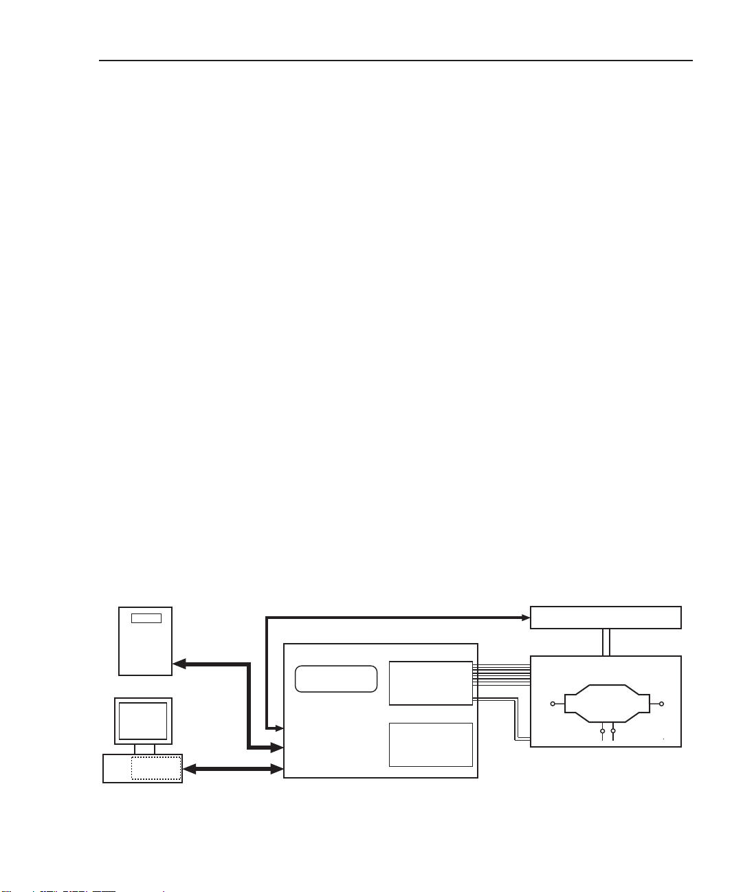
Figure 1-1 shows a typical test system using a programmable logic controller (PLC) or a
PC. When using a PLC, communications with Model 2790 are done over the RS-232
interface. When using a PC, communications with the Model 2790 can be provided using
the GPIB or RS-232.
Figure 1-1
System connections
PLC
or PC
(RS-232)
OR
PC
(GPIB)
KPCI-488
Interface
RS-232
GPIB
Keithley 2790
MATH
2.790000
DIGITAL I/O
RS-232
IEEE-488
Device Handler Control
Slot 1
7751, 7752, or
Ω
7753 Module
Interlock
Slot 2
Test
System
Expansion
Test Signal
Cabling
Device Handler
Mechanical
Connection
Test Station
(with Interlock)
Inflator Under
Test
Interlock
Page 17

1-6 Model 2790 SourceMeter® Switch System User’s Manual
Inflator tests
There are three primary tests for an inflator:
• Shunt bar test
• Bridgewire test
• Insulation resistance (HIPOT) test
NOTE Interlock – The three primary tests can only be performed if the interlock of the
7751/7752/7753 module is enabled. With interlock open (disabled), the I-source
of the 7751/7752/7753 module and the V-source of the 7751/7753 module are
disconnected from the switching module matrix. Details on the interlock are provided in Section 5.
The following information provides an overview of the three tests that are used
to test an inflator. The actual detailed procedures for these tests are provided in
Section 5.
Shunt bar test
NOTE A shunt bar test is typically tested again after all other inflator tests are completed.
As a final test, it verifies that it is safe to install the inflator in a vehicle.
A shunt bar (shorting clip) is used to short the bridgewire(s) to prevent accidental ignition
when handling or installing the inflator. However, an oxide can form between the shunt
and the inflator terminals. It is this high-resistance oxide that diminishes the ability of the
shunt bar to act as an effective short across the bridgwire(s). Without a good contact short,
detonation could occur. The measured resistance of a shunt bar is typically between 10 to
100mΩ.
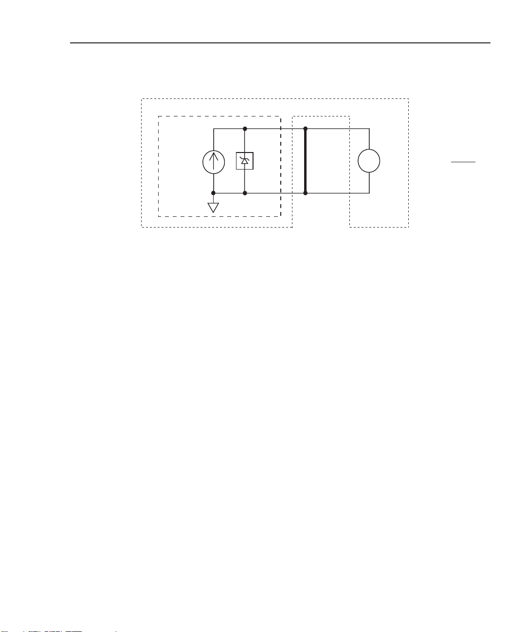
One method used for the shunt bar test is shown in Figure 1-2. In this case, the dry circuit
mode of the 7751/7752/7753 clamps voltage at 20mV (1mA maximum) for the constant
test current of the I-source. This low voltage will not pierce the oxide. With the low ohms
math function (SxIohms) selected, the R
play of the Model 2790.
reading can be read directly from the dis-
SHUNT
Page 18
Model 2790 SourceMeter® Switch System User’s Manual 1-7
Figure 1-2
Shunt bar testing
Keithley 2790 SourceMeter Switch System
Keithley
7751,7752,
or 7753
Module
I
SOURCE
(1mA max)
20mV
Dry
Ckt
Shunt Bar
Under
Test
(R
SHUNT)
v
2790
DMM
RSHUNT =
MEAS
V
ISOUR
NOTE If required, a more accurate resistance measurement of the shunt bar can be
achieved by disabling the dry circuit and using a test current of 50mA. An even
more accurate resistance measurement can be achieved using the Ω4 function of
the Model 2790. Keep in mind that this is an additional test and does not replace
the test using the dry circuit.
NOTE Use this 2-step process to detect the presence of oxide build-up and more
accurately measure the resistance of the shunt bar:
1. Test the shunt bar using dry circuit ohms (channel 24 closed) and a test
current of 1mA. A resistance >100mΩ indicates the presence of oxide
build-up.
2. Accurately measure shunt bar resistance without dry circuit (channel 24
open) and a test current of 50mA or use the Ω4 function of the Model 2790.
Section 6 explains how to use the Ω4 function of the Model 2790 with the
7702 or 7751/7752/7753 module.
Page 19
1-8 Model 2790 SourceMeter® Switch System User’s Manual
Bridgewire test
The air bag inflator has two terminals connected to a bridgewire, which is coated with a
primer that ignites when sufficient current passes through the wire. The bridgewire’s resistance is typically from two to three ohms (2Ω being the most common). To avoid unintended
ignition, the level of test current applied is generally 50mA or less.
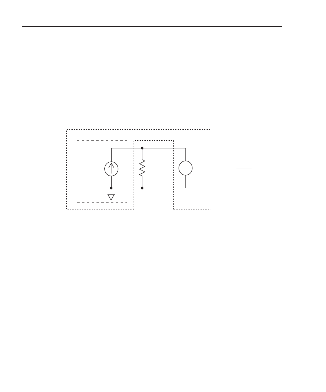
As shown in Figure 1-3, a fixed current is sourced through the bridgewire. The voltage
across the bridgewire is then measured by the DMM of the Model 2790.
Figure 1-3
Bridgewire testing
Keithley 2790 SourceMeter Switch System
Keithley
7751,7752,
or 7753
Module
I
SOURCE
Bridgewire
Under
Test
(RBRID)
v
2790
DMM
RBRID =
MEAS
V
ISOUR
With the low ohms math function selected, the R
reading can be read directly from
BRID
the display of the Model 2790.
I-source readback — Before performing the bridgewire test, you can verify the actual
current flowing in the test circuit by using the I-source readback circuit.
NOTE A more accurate ohms reading can be achieved using the Ω4 function of the
Model 2790 (1mA fixed). See Section 6 for details.
Page 20
Model 2790 SourceMeter® Switch System User’s Manual 1-9
Insulation resistance (HIPOT) test (7751 and 7753 only)
WARNING The Models 7751 and 7753 are provided with outputs that are poten-
tially hazardous if not connected properly. It is the responsibility of the
customer to operate instruments in a safe manner. Be sure to read and
follow all installation and operating instructions before attempting to
use the 7751/7753 HIPOT function.
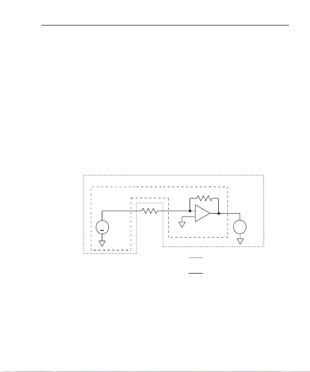
The leakage resistance (R
) between each of the initiators and the housing must be
HIPOT
verified. As shown in Figure 1-4, this is performed by applying a voltage, typically 500V,
between the bridgewire and the housing. The resultant test circuit current is applied to an
I/V amplifier, where it is converted to a voltage. This voltage is then measured by the
DMM of the Model 2790.
NOTE If not using a 7751/7753 module in your test system, resistance up to 120MΩ
can be measured using the Ω2 function of the Model 2790.
Figure 1-4
HIPOT testing (7751/7753)
Keithley 2790 SourceMeter Switch System
Keithley 7751/7753 Module
RF
–
+
I/V Amplifier
(7751/7753)
SOUR
V
x RF
VMEAS
500V
x R
MEAS
V
v
RF = 200kΩ (7751)
F = 20kΩ (7753)
R
F
2790
DMM
+
V
SOURCE
(500V)
RHIPOT
RHIPOT = –
= –
Page 21

1-10 Model 2790 SourceMeter® Switch System User’s Manual
With the high ohms math function (SxVohms) selected, the R
reading can be read
HIPOT
directly from the display of the Model 2790.
Before measuring R
, there are a couple of preliminary verification tests that should
HIPOT
be performed first:
• Contact checks — To properly perform the HIPOT test, contact must be made to
the air bag inflator housing. If good contact is not established, the measured high
resistance will not represent the isolation resistance. Contact is checked by performing continuity checks through the V-source test leads and the connection
points. The resistance reading for a contact should be less than 20 ohms (depending
on cabling).
• V-source readback — Before performing the HIPOT test, the output voltage of the
V-source should be verified. The V-source readback circuit allows you to directly
measure the output voltage using the DMM of the Model 2790.
Page 22

2
Keithley 7751, 7752, and 7753
Switching Modules
• Card configuration — Provides the simplified schematic of the Keithley 7751,
7752, and 7753 switching modules. Summarizes the individual components of the
modules.
• Setting source output levels — Explains how to set the output levels for the
I-source (7751/7752/7753) and V-source (7751/7753).
• Math — Covers the ohms math functions used to calculate low resistance when
using the I-source of the 7751/7752/7753, and high resistance when using the
V-source and I/V amplifier of the 7751/7753 module.
• Opening and closing channels — Explains how to open and close channels for the
7751, 7752, and 7753 modules.
• Viewing closed channels — Explains how to display closed channels on the
Model 2790.
• Open interlock errors — Explains the errors associated with an open interlock.
• Cable discharge circuit (7751 and 7753) — Explains the cable discharge circuit. It
dissipates voltage at the input channels. This unwanted voltage could ignite the
inflator.
• Connection log — Use to record connection information.
• Using memory patterns — Describes the memory patterns feature, which can be
used to simplify repetitive test procedures.
Page 23

2-2 Model 2790 SourceMeter® Switch System User’s Manual
NOTE Module wiring and installation into the mainframe of the Model 2790 is covered
in Section 4.
Details on using the Keithley 7751, 7752, 7753 modules to test inflators are
provided in Section 5.
The edit keys (left, right, up, and down arrow keys) are used to display menu
items and output levels. With the desired menu item or output level displayed, it
is selected by pressing ENTER.
For remote programming, the <clist> parameter is used as follows:
<clist> = (@SCH)
where: S = Mainframe slot number (1 or 2)
CH = Switching module channel number of source (2 digits)
Examples: (@101) = Slot 1, Channel 1
(@101, 114, 118) = Slot 1, Channels 1, 14, and 18
Card configuration
CAUTION External energy sources should never be applied directly to a 7751,
7752, or 7753 module for any reason. Damage to the module and any
connected devices under test can result due to the application of
improperly selected or performing external energy sources.
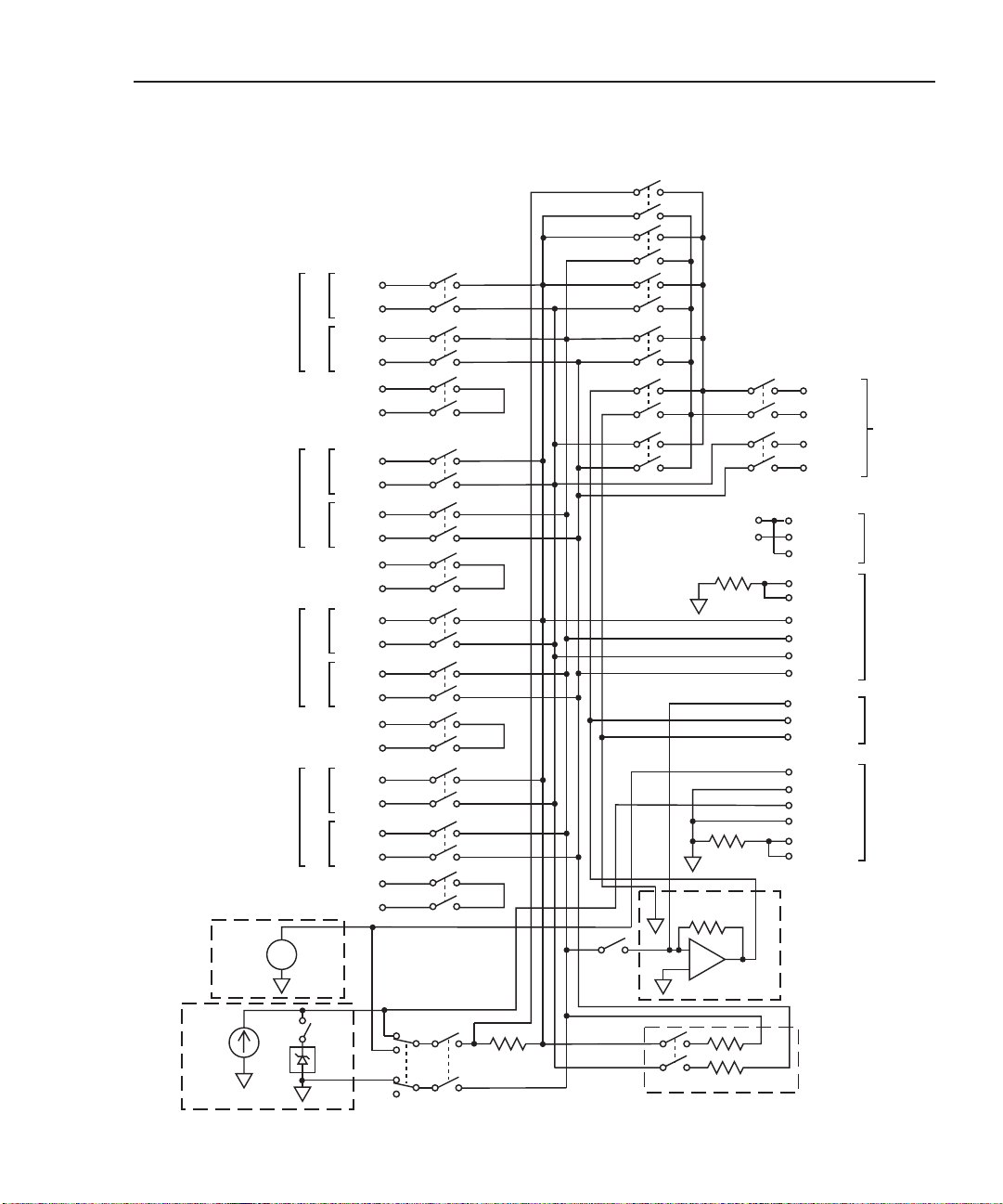
The simplified schematic for the 7751, 7752, and 7753 is provided in Figure 2-1.
• Channels 1-12 — Input channels for DUT (inflator).
• Channels 13-19 and 25 — Routes test signals to backplane of Model 2790.
• Channels 20-24, 27, and 28 — Control individual components of the 7751/7752/7753.
Page 24
Model 2790 SourceMeter® Switch System User’s Manual 2-3
Figure 2-1
Simplified schematic of Keithley 7751, 7752, and 7753 switching modules
Ch. 25
Ch. 13
Vsource
Ch. 28
(7751/7753
Only)
50-500V
Bank 1
J101
Bank 2
J102
Bank 3
J103
Bank 4
J104
Source
HI
Sense
Source
LO
Sense
Source
HI
Sense
Source
LO
Sense
Source
HI
Sense
Source
LO
Sense
Source
HI
Sense
Source
LO
Sense
+
–
Ch. 1
Ch. 2
A1
Ch. 3
B1
Ch. 4
Ch. 5
A2
Ch. 6
B2
Ch. 7
Ch. 8
A3
Ch. 9
B3
Ch. 10
Ch. 11
A4
Ch. 12
B4
Ch. 14
Ch. 15
Ch. 16 Ch. 18
Ch. 17
Ch. 23
Ch. 19
Source Enable
10kΩ
10kΩ
200kΩ (7751)
20kΩ (7753)
–
+
+5V
HI
Input
LO
HI
Sense
LO
Interlock
+5V
Interlock
Guard
Guard
Source HI
Source LO
Sense HI
Sense LO
I/V IN
I/V OUT
I/V LO
Vsrc HI
Vsrc LO
Isrc HI
Isrc LO
Guard
Guard
I/V
Current/Voltage
Amplifier
(7751/7753 Only)
To Model
2790
Backplane
J106
J105
J108
J107
Isource
Ch. 27
0-50mA
Ch. 24
20mV
Dry
Ch. 22
Ckt
Ch. 22 Open: I-source Select
Ch. 22 Close: V-source Select
Ch. 21
1Ω
Ch. 20
100kΩ
Cable Discharge
(7751/7753 Only)
Page 25

2-4 Model 2790 SourceMeter® Switch System User’s Manual
I-source – channels 21, 22, 24, and 27
The programmable I-source (0 to 50mA) is used as the test current to measure low resistance (inflator bridgewires and shunt bars).
• The I-source is designated as channel 27.
• Opening channel 22 selects the I-source.
• Closing channel 21 connects the I-source.
• Closing channel 24 connects the dry circuit clamp for the shunt bar test (20mV,
1mA limit).
NOTE “Ohms specification calculations” in Appendix A explains how to determine the
accuracy specification for source levels not specified in the “7751/7752/7753
Source/Switch Module Specifications” sheet.
V-source and I/V amplifier (7751/7753 only) – channels 21, 22, 23, 28
The programmable voltage source (50 to 500V) and I/V amplifier are used to measure
high resistance (insulation resistance of an inflator).
• The V-source is designated as channel 28.
• Closing channel 22 selects the V-source.
• Closing channel 21 connects the V-source.
• Closing channel 23 connects the I/V amplifier.
WARNING Do not connect V-source Hi to earth ground. The 7751/7752/7753 mod-
ule uses a floating ground. This floating ground is not connected to
safety earth ground. Not only will it create a shock hazard by floating
up to 500V, it will also effectively connect a 1nF capacitor across the
V-source, providing energy storage that could ignite an airbag under
fault conditions.
NOTE “Ohms specification calculations” in Appendix A explains how to determine the
accuracy specification for source levels not specified in the “7751/7752/7753
Source/Switch Module Specifications” sheet.
Cable discharge (7751/7753 only) – channel 20
A cable discharge circuit is used to dissipate charge build-up on the inputs to prevent accidental ignition of the inflator. For details, see “Cable discharge circuit”.
• Closing channel 20 discharges voltage on the input channels.
Page 26

Model 2790 SourceMeter® Switch System User’s Manual 2-5
Source readback – channels 13 and 25
The actual output of the selected source can be verified by using source readback, which
routes the selected source back to the DMM of the 2790 for measurement. I-source and
V-source readback are explained in Section 5.
• Opening channel 22 and closing channels 21, 25, and 18 connects the I-source
sense resistor to the DMM of the Model 2790.
• Closing channels 22, 21, 13, and 18 connects the V-source to the DMM of the
Model 2790.
Interlock – J106
A 7751/7752/7753 module has an interlock to disconnect its I-source and V-source from
the rest of the switch matrix. In order to use the module sources, interlock must be
enabled. The interlock switch of a test station is connected to the J106 terminals of the
module. When the interlock switch is open (i.e., safety shield open), the sources cannot be
connected to the switch matrix. Details on interlock are provided in Section 5.
NOTE The Interlock switch does not affect the output of J107. Voltage can still be present
at those terminals even if the interlock is disabled. See “General purpose terminal
blocks – J105, J107, and J108” for additional details.
General purpose terminal blocks – J105, J107, and J108
There are quick-disconnect terminal blocks available to the user to provide access to various
switching module components. These are provided for general purpose test applications that
are not necessarily related to airbags.
J105 (matrix backplane and guard)
The backplane terminals provide access to the relay matrix backplane. The matrix backplane
is the primary “artery” for signal routing though the module.
The guard terminals are typically used for shielding when using the V-source and I/V converter for high ohms measurements. Guard connections are explained in Section 4.
J107 (source outputs and guard)
The I-source and V-source (7751/7753) are always on and can be accessed by the user at
J107. The programmed output is routed to these terminals.
The guard terminals are typically used for shielding when using the V-source and I/V
converter for high ohms measurements. Guard connections are explained in Section 4.
Page 27

2-6 Model 2790 SourceMeter® Switch System User’s Manual
J108 (I/V converter)
The user also has access to the input, output, and ground of the I/V converter at J108.
Safety warnings
WARNING Integrated safety features protect the 7751/7752/7753 module from its
built-in I-source and V-source. However, if an external source (such as
the 12V car bus) is connected to the front panel inputs of the Model 2790
or through a 7702 module, these safety features are compromised, creating the very real possibility of igniting the airbag. Incorrect channel closures in the test system could inadvertently apply the external source to
the inflator and ignite it. Damage to the 7751/7752/7753 module may
also occur if an external source is connected to it.
WARNING Since the Model 2790 system is not an intrinsically safe device, it is the
responsibility of the user to ensure that external protection be provided, either by an inherently safe electrical barrier and/or a safety barrier around the DUT or airbag, to prevent injury in case of detonation.
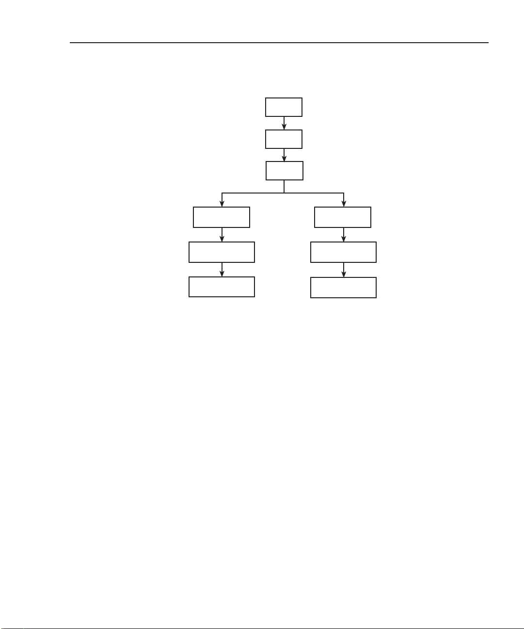
Setting source output levels
I-source and V-source (7751/7753) output levels are set from the CONFIG item of the
CARD menu. The menu structure, shown in Figure 2-2, is accessed by pressing and
releasing SHIFT and then pressing CARD.
• I-source — Set output from 0 to 50mA. In the menu structure, the I-source is designated as channel 27. The default setting is 1mA.
•V-source (7751/7753 only) — Set output from 50 to 500V. In the menu structure,
the V-source is designated as channel 28. The default setting is 50V.
NOTE When using the V-source as an independent source, limit 7751 output current to
50µA or 7753 output current to 500µA to achieve rated accuracy. Typical short
circuit current is <1mA.
Page 28
Model 2790 SourceMeter® Switch System User’s Manual 2-7
Figure 2-2
Setting I-source and V-source output levels
Press
Press
Select
SLOT1: 77xx
7751
7752
7753
7751
7753
I-C27:01.00 mA
V-C28:050.0 V
* 7753 should be installed in slot 1 for rated accuracy.
SHIFT
CARD
CONFIG
77xx =7751/7752/7753
Select module
Set I-source
output
Set V-source
output
SLOT2: 77xx
I-C27:01.00 mA
V-C28:050.0 V
7751
7752
7753*
7751
7753*
Page 29

2-8 Model 2790 SourceMeter® Switch System User’s Manual
Remote programming
As shown in Table 2-1, the amplitude command is used to set the outputs of the sources.
Notice that the channel number of the V-source (28) and I-source (27) must be included in
the command string.
Table 2-1
Commands to set amplitude for V-source and I-source
Commands Description Default
SOURce:VOLTage[:LEVel][:IMMediate]
[:AMPLitude] <NRf>, <clist> Set V-source output; 50 to 500 (V).
50V
<clist> = (@128) Slot 1
= (@228) Slot 2
[:AMPLitude]? <clist> Query V-source output level.
SOURce:CURRent[:LEVel][:IMMediate]
[:AMPLitude] <NRf>, <clist> Set I-source output; 0 to 50 (mA).
0.001A
<clist> = (@127) Slot 1
= (@227) Slot 2
[:AMPLitude]? <clist> Query I-source output level.
Note: Selecting an ohms calculation enables source tracking. Selecting any other math function disables
source tracking.
Page 30

Model 2790 SourceMeter® Switch System User’s Manual 2-9
Math
There is a shortcut math function to calculate low resistance when using the I-source of a
7751/7752/7753 module, and one to calculate high resistance when using the V-source and
I/V amplifier of a 7751/7753 module.
Low ohms calculation (SxIohms)
• SxIohms – Calculates and displays low resistance reading for 7751/7752/7753
module in slot x (where x =1 or 2).
This ohms function is a shortcut for the mX+b calculation. When selected, the following
“m” and “b” factors are used:
m = 1 / I
SOUR
b = 0
Calculation: R = mX + b
= (1/ I
= V
where: I
SOUR
MEAS
is the programmed current level of the I-source of the 7751, 7752, or
SOUR
/ I
) x V
SOUR
MEAS
+ 0
7753.
1 / I
V
MEAS
is the “m” factor for the calculation (mX+b).
SOUR
is the voltage measured by the DMM of the Model 2790. It is the “X”
variable for the calculation (mX+b).
When the SxIohms calculation is selected, the Model 2790 measures voltage (X) and
calculates mX+b using the above factors. The displayed reading will be in ohms (Ω). This
selection also sets DMM to DCV, 1V range.
NOTE SxIohms cannot be selected if the I-source is set to 0mA. Since “m” = 1 / I
SOUR
dividing 1 by 0 would result in an erroneous reading (positive infinity).
When using the low ohms calculation, the highest DCV measurement range that can be
selected is 1V. Attempting to select a higher range will cause error -222 (Parameter out of
range). Attempting to turn Autoranging on generates error -221 “Settings conflict” over
the GPIB or a “NO AUTORANGE” message on the display if done from the front panel
AUTO key.
Page 31

2-10 Model 2790 SourceMeter® Switch System User’s Manual
High ohms calculation (SxVohms)
• SxVohms – Calculates and displays the high resistance reading for the 7751/7753
module in slot x (where x =1 or 2).
This ohms function is a shortcut for the m/X+b calculation. When selected, the following
“m” and “b” factors are used:
m = -200,000 x V
m = -20,000 x V
SOUR
SOUR
(7751)
(7753)
b = 0
7751 calculation: R = m/X + b
= (-200,000 x V
= -V
SOUR
/ V
MEAS
SOUR
x 200,000
) / V
MEAS
+ 0
7753 calculation: R = m/X + b
where: V
= (-20,000 x V
= -V
is the programmed voltage level of the V-source of the 7751/7753.
SOUR
SOUR
/ V
For the 7751, (-200,000 x V
) / V
SOUR
x 20,000
MEAS
) is the “m” factor for the calculation (m/X+b).
SOUR
MEAS
+ 0
200,000 is the value of the feedback resistor (RF) for the I/V amplifier
(RF = 200kΩ).
For the 7753, (-20,000 x V
) is the “m” factor for the calculation (m/X+b).
SOUR
20,000 is the value of the feedback resistor (RF) for the I/V amplifier (RF = 20kΩ).
V
is the output voltage of the V/I amplifier measured by the DMM of the
MEAS
Model 2790. It is the “X” variable for the calculation (m/X+b).
When the SxVohms calculation is selected, the Model 2790 measures voltage (X) and
calculates m/X+b using the above factors. The displayed reading will be in ohms (Ω). This
selection also sets DMM to DCV, 10V range. Note that the V
reading will be negative
MEAS
(-). Because the output of the V/I amplifier is inverted, the negative value of “m” will cause
the ohms reading to be displayed as a positive value.
When using the high ohms calculation (SxVohms), the highest DCV measurement range
that can be selected is 10V. Attempting to select a higher range will cause error -222
(Parameter out of range).
If V> - 10mV, an overflow will occur. If V< -12V, an underflow will occur.
Attempting to turn Autoranging on generates error -221 “Settings conflict” over the GPIB
or a “NO AUTORANGE” message on the display if done from the front panel AUTO key.
NOTE Readings for both the 7751 and 7753 modules will overflow when the I/V output
is greater than -9mV and underflow when the I/V output is less than -12V.
Page 32

Model 2790 SourceMeter® Switch System User’s Manual 2-11
Front panel operation
An ohms math function is enabled from the MATH menu, which is accessed by pressing
and releasing SHIFT and then MATH (see Figure 2-3). Note that an ohms math function is
only available in the menu if the associated 7751, 7752, or 7753 module is installed.
Figure 2-3
Enabling ohms math function
Press
Press
Select math
function
SHIFT
MATH
S1IOHMS S1VOHMS S2IOHMS S2VOHMS
7751/7752/7753
in slot 1
* 7753 should be installed in slot 1 for rated accuracy.
Remote programming
As shown in Table 2-2, the :CALC:FORMat command is used to select an ohms math
function. Notice that the math setting can be global to all qualified channels or set on a
per-channel basis by using the <clist> parameter.
NOTE With an ohms math function selected, the Model 2790 is actually measuring
DCV. Therefore, if you send SENS1:FUNC? to query the selected function, it
will return “VOLT:DC”.
Source tracking
7751/7753
in slot 1
7751/7752/7753*
in slot 2
7751/7753*
in slot 2
The Model 2790 provides source tracking to ensure that the most recently set source
amplitude is used in the selected ohms calculation. If the source output level changes, the
“m” constant for the calculation will change accordingly.
Source tracking is enabled automatically when the desired ohms function is selected. No
other actions are required by the user.
However, if desired, source tracking can be disabled or the source that is being tracked can
be changed. The :TRACk and :SOURCe commands are listed in Table 2-2.
Page 33

2-12 Model 2790 SourceMeter® Switch System User’s Manual
Table 2-2
Commands to select ohms calculations
Commands Description Default
CALCulate[1]:FORMat <name> Select math function: NONE, MXB,
PERC
PERCent, RECiprocal, S1Iohms,
S1Vohms, S2Iohms, S2Vohms.
CALCulate[1]:FORMat? Query selected math format.
CALCulate[1]:STATe <b> Enable or disable math calculation.
CALCulate[1]:STATe? Query state of selected math calculation.
CALCulate[1]:DATA[:LATest]? Return last result of calculation.
CALCulate[1]:DATA:FRESh? Return last “fresh” result of calculation.
The following commands are set automatically when an ohms math function (SxIohms or SxVohms) is selected using the :FORMat command. No further actions are required by the user.
CALCulate[1]:KMATh:MMFactor:TRACk <b> Enable or disable source tracking1. OFF
CALCulate[1]:KMATh:MMFactor:TRACk? Query state of source tracking.
CALCulate[1]:KMATh:MMFactor:SOURce <name> Selects source to be tracked: NONE,
NONE
S1ISource, S1VSource, S2ISource,
S2VSource.
CALCulate[1]:KMATh:MMFactor:SOURce? Query source to be tracked.
1
Selecting an ohms calculation enables source tracking. Selecting any other math function disables source tracking.
Programming errors
-222 Parameter out of range — Attempted to select a source (:SOURCe command)
with a 7702 card installed.
-241 Hardware missing — Attempted to select a source (:SOURCe command) that is
not installed.
+870 Invalid current error — Attempted to track an I-source that is set to 0mA. For
the low ohms calculation, “m” = 1 / I
erroneous reading (positive infinity).
. Dividing 1 by 0 would result in an
SOUR
Page 34

Model 2790 SourceMeter® Switch System User’s Manual 2-13
Opening and closing channels
Multiple channel operations are used to control 7751, 7752, and 7753 channels:
• Only the specified channels are opened or closed. Unspecified channels are not
affected.
• Relays to connect signals to the backplane (DMM) of the Model 2790 do not close
automatically. You must explicitly close them to perform a measurement. For
example, with a DUT connected to channel 1 of a 7751, 7752, or 7753 module, you
would have to close channels 1, 14, and 18 to measure it with the Model 2790.
• Closed channels are not displayed by the Model 2790 while in the normal display
state. Closed channels can be viewed from the VIEW item of the CARD menu (see
“Viewing closed channels” for details).
To control the appropriate switching module, the slot number must be included with the
switching module channel number. The channel assignment is formatted as follows:
SCH where: S is the slot number (1 or 2)
CH is the channel number
Examples: 101 = Slot 1, Channel 1
218 = Slot 2, Channel 18
NOTE Interlock of the 7751/7752/7753 must be enabled in order to close channel 18,
19, or 21 and open channel 20. See “Open interlock errors” for errors associ-
ated with open interlock and see “Interlock” in Section 5 for details on using the
interlock.
Front panel operation
As shown in Figure 2-4, the OPEN and CLOSE keys are used to control 7751, 7752, and
7753 channels:
After closing or opening a single channel:
•A message indicating the action (i.e., “101 CLOSED”) will be displayed briefly.
•To close another channel, simply key in the channel number and press ENTER.
• Press EXIT to exit from the open/close menu structure.
NOTE The edit keys (left, right, up, and down arrow keys) are used to display a channel
number. Pressing ENTER opens or closes the channel.
Page 35

2-14 Model 2790 SourceMeter® Switch System User’s Manual
Figure 2-4
Opening and closing channels
A) Opening one or all channels
Display ALL option
and press OPEN again
B) Closing a channel
CLOSEOPEN
CLOSE:MULT
CLOSE MULT:XXX
Remote programming
The commands to control 7751, 7752, and 7753 channels are listed in Table 2-3.
Table 2-3
Commands to control 7751/7752/7753 module channels
OPEN: ALL
Press CLOSE key
Display MULT option
and press ENTER
Specify channel number
(XXX) and press ENTER
CLOSEOPEN
Press OPEN key
OPEN: MULT
OPEN MULT:XXX
Display MULT option
and press ENTER
Display channel number
(XXX) and press ENTER
Commands Description
ROUTe:MULTiple:CLOSe <clist> Specify one or more channels to close.
ROUTe:MULTiple:OPEN <clist> Open channels specified in list. Unlisted
channels not affected.
ROUTe:OPEN:ALL Open all channels*.
ROUTe:MULTiple:CLOSe? Returns a <clist> of all closed channels.
ROUTe:MULTiple:CLOSe:STATe? <clist> Query closed channels in specified list;
0 = open, 1 = closed.
* ROUT:OPEN:ALL will open all channels, except channel 20 if interlock is open.
Examples: ROUT:OPEN:ALL ‘ Open all channels.
ROUT:MULT:CLOS (@101,114,118) ‘ Close channels for slot 1.
ROUT:MULT:CLOS? ‘ Return list of closed channels.
Page 36

Model 2790 SourceMeter® Switch System User’s Manual 2-15
Viewing closed channels
Closed channels can be viewed from the VIEW item of the CARD menu. The menu structure is accessed by pressing and releasing SHIFT and then pressing CARD. As shown in
Figure 2-5, the closed channels will scroll across the display:
• The four dots (....) identify the end of the channel string.
• Use the ENTER key to pause and resume scrolling.
• Press EXIT to return to the normal display state.
NOTE For remote programming, closed channels can be identified using
ROUT:MULT:CLOS? and ROUT:MULT:CLOS:STAT? (see Table 2-3).
Figure 2-5
Viewing closed channels
Select module
Closed channels
scrolled*
Press
Press
Select
SHIFT
CARD
VIEW
SLOTx: 77xx
101, 114, 118 ....
SLOTx = Slot1 or Slot2
77xx = 7751/7752/7753**
*
Shows channels 101, 114,
and 118 closed.
** 7753 should be installed in
slot 1 for rated accuracy.
Page 37

2-16 Model 2790 SourceMeter® Switch System User’s Manual
Open interlock errors
The 7751, 7752, and 7753 modules have an interlock. When the interlock is open (disabled),
the I-source (7751, 7752, and 7753) and V-source (7751 and 7753) are disconnected from
the switching matrix. Details on enabling the interlock are explained in Section 5. The following errors are associated with an open interlock.
Front panel messages:
• INTRLCK OPEN is displayed briefly if you attempt to close channel 18, 19, or 21
with interlock open.
•With the INPUTS switch in the REAR position (in), readings will overflow
(OFLO) when the interlock is open.
• In the case of the OFLO readings for open interlock, the IL1 or IL2 message will
also be displayed. IL1 is displayed for a slot 1 violation and IL2 is displayed for a
slot 2 violation. In the case of errors for both slots, the IL1 message takes
precedence.
•Overflowed readings stored in the buffer do not provide interlock status. You cannot
tell if the overflow readings are true overflows or the result of open interlock (see
“Remote programming errors”, below).
Remote programming errors:
• When an open interlock is first detected, error +860 (slot 1 interlock violation)
or +861 (slot 2 interlock violation) occurs. The questionable event register in the
status byte can be read to determine which interlock tripped (see Section 11 of the
Model 2790 Reference Manual).
• The firmware polls for interlock violations every 50msec. To avoid filling up the
error queue, once an error is issued for a given interlock, it must be reset (interlock
enabled) before another error event will be issued to the status model for the same
interlock.
• Error -224 (parameter error) occurs if you attempt to close channel 18, 19, or 21
with interlock open.
•With interlock open, channel 20 will close and remain closed while interlock is
open. ROUT:OPEN:ALL will open all channels except channel 20.
ROUT:MULT:OPEN will generate error -224 (parameter error).
Page 38

Model 2790 SourceMeter® Switch System User’s Manual 2-17
Cable discharge circuit (7751 and 7753)
Leakage capacitance exists between signal paths on the switching module and in the test
cables. This capacitance can be high enough to store a high voltage charge from the
V-source of the 7751/7753 module.
As shown in Figure 2-6, capacitance exists between the source terminals (CSO) and the
sense terminals (CSE). These capacitors can be charged by the V-source of the 7751/7753
module during the HIPOT test. This unwanted voltage charge could ignite the inflator if it
is connected to a bridgewire.
To prevent a high voltage charge from appearing across the inflator, a discharge circuit is
used. As shown in Figure 2-6, channel 20 is closed to provide discharge paths through
100kΩ resistors.
In general, the discharge circuit is controlled as follows:
• When the interlock opens, channel 20 closes to discharge the capacitors. Channel 20
remains closed as long as interlock remains open (see “Interlock” in Section 5 for
details).
• Opening channel 22 closes channel 20 for approximately 5msec to discharge the
capacitors. Opening channel 22 selects the I-source (V-source disconnects from
rest of module and DUT).
In general, with the test cables connected to the module and the input channels (i.e., 1 and
2) closed, the following sequence should be used to properly perform cable discharge:
1. Open channel 21 to disconnect the V-source and I-source from the input.
2. Open channel 22 to perform cable discharge.
NOTE If channel 22 is already open, performing the MULT:OPEN operation will not
close channel 20 to perform cable discharge. However, the OPEN:ALL operation will perform cable discharge.
When the OPEN:ALL operation is performed, the following sequence of actions
occur:
1) Opens channel 21 to disconnect all sources.
2) Opens channel 22.
3) Closes channel 20 for 5msec to perform cable discharge.
4) Opens all channels.
NOTE In Section 5, the test procedure for HIPOT uses the OPEN:ALL operation to
perform cable discharge (see steps 7 and 11 in Table 5-6).
Page 39

2-18 Model 2790 SourceMeter® Switch System User’s Manual
Manual cable discharge
The discharge circuit can also be activated manually at any time by closing channel 20 of
the 7751/7753 module. Typically, manual discharge is used when a discharge time >5msec
is desired.
Figure 2-6
Cable discharge circuit
Keithley 7751/7753
Source
Inflator
Under
Test
LO
HI
Sense
Source
Sense
20
= Closed channel switches.
CSO
~1nF
100kΩ
100kΩ
C
SE
~1nF
Page 40

Model 2790 SourceMeter® Switch System User’s Manual 2-19
Connection log
Make a copy of Table 2-4 and affix it to the cover of the 7751/7752/7753 module. Use it to
record connection information and channel descriptions as needed.
Table 2-4
Connection log Model 7751/7752/7753
Bank Channel Color Description
CH1 (HI) Source
Sense
Bank 1CH2 (LO) Source
Sense
CH3 A1
B1
CH4 (HI) Source
Sense
Bank 2CH5 (LO) Source
Sense
CH6 A2
B2
CH7 (HI) Source
Sense
Bank 3CH8 (LO) Source
Sense
CH9 A3
B3
CH10 (HI) Source
Sense
Bank 4CH11 (LO) Source
Sense
CH12 A4
B4
Page 41

2-20 Model 2790 SourceMeter® Switch System User’s Manual
Using memory patterns
Firmware revision level
Memory patterns are supported in Model 2790 units with firmware A04 and higher. The
firmware revision level is displayed as part of the power-up cycle.
Overview
Most Model 7751/7752/7753 tests follow the same basic procedure: select a source and set
its level, configure the Model 2790 measurement, close the necessary relays, and take a reading. Memory Patterns simplify this process, allowing you to store combinations of multiple
closed channels, source settings, and DMM measurement configurations in nonvolatile
memory. Up to 40 such Memory Patterns, designated M1 through M40, can be stored. There
is also memory pattern M0, which is defined as an “all-open” pattern. Recalling M0 opens
all channels and resets all sources to their factory default values. Similar to closing one 7702
channel and taking a reading, you can recall an individual Memory Pattern to close multiple
channels and take a reading. More importantly, you can include Memory Patterns in a scan
list and cause the Model 2790 to automatically scan through the specified memory locations.
As each memory pattern is scanned, the sources and DMM are configured appropriately, the
specified group of channels is closed, and a reading is taken. Reading limits can also be
assigned to each memory pattern so that during a scan the readings will automatically be
inspected for PASS/FAIL conditions. Digital outputs corresponding to these conditions are
also available.
NOTE Memory patterns can be used only with the following functions: DC volts, 2-wire
ohms, and 4-wire ohms.
Front panel operation
Memory patterns cannot be defined from the front panel, but they can be recalled once
defined by remote commands (see below). To recall defined memory patterns from the
front panel:
1. Press CLOSE.
2. Use the RANGE and keys to select CLOSE: MEMORY, then press
ENTER.
3. Use , , , and to select the memory pattern number (1-40), then press
ENTER.
Page 42

Model 2790 SourceMeter® Switch System User’s Manual 2-21
Memory pattern commands
Memory patterns commands are summarized in Table 2-5. See Section 2 of the Model
2790 Reference Manual for details on these commands.
Command Description
:ROUTe:MEMory[:CHANnels] <n>, <clist> Create channel pattern for memory <n> (1-40).
Note: 7702 channels cannot be included in
<clist>.
:ROUTe:MEMory:SOURce:LEVel <n>, <NRf>, <clist> Assign source values to the channels in <clist>
that will be output when memory pattern <n>
is executed. (Source channels only: 127, 128,
227, or 228.)
:ROUTe:MEMory:DELay <n>, <NRf> Assign a variable delay to memory pattern
<n>. (Time in seconds after closing channels
and setting source values before making
measurements.)
:ROUTe:MEMory:RECall <n> Immediately execute memory pattern <n>.
:ROUTe:MEMory:READ[:STATe] <n>, <b> If set to ON, a reading will be collected after
the memory pattern has executed (applies to
scanning only). *
:ROUTe:MEMory:CLEar <n> Clear out memory pattern <n>, setting all
channels to open and removing all digital and
analog channels from this memory pattern.
:ROUTe:MEMory:CLEar:ALL Clear out all memory patterns.
* You must include at least one measurement channel or a memory pattern that takes a reading (ROUT:MEM:READ:STAT x, ON).
Failure to do so results in the scan list being rejected with Error +702, “No measurement channel in scanlist.”
Setting up and executing memory patterns
To set up memory patterns, use the following procedure:
1. Program the desired memory pattern locations using the ROUT:MEM commands.
Typically, you would set source value(s), define channels to close, and set up delay
for each memory location.
2. Define DCV, 2-wire ohms, or 4-wire ohms measurement function(s) for each memory
pattern location.
Page 43

2-22 Model 2790 SourceMeter® Switch System User’s Manual
3. Once a location is defined, use the ROUT:MEM:REC command to recall a memory pattern location, then trigger and acquire a reading using READ?
4. After taking the measurement, use ROUT:OPEN ALL to open all channels.
An example that sets up and executes memory location #1 is shown in Table 2-5. See
“Memory patterns test” on page 5-30 for a more detailed example.
Table 2-5
Basic memory pattern example
Command Description
:ROUT:MEM:CHAN 1,(@108,115,118) Specify relays to close.
:ROUT:MEM:DEL 1,0 Set memory delay = 0.
:SENS:FUNC 'RES',(@M1) Select 2-wire ohms measurement function.
:SENS:RES:RANG 100,(@M1) Select 100Ω fixed measurement range.
:SENS:RES:NPLC 1,(@M1) Set A/D integration time to 1 power line cycle.
:ROUT:MEM:REC 1 Recall Memory Location 1.
:READ? Initiate a measurement and request the result.
:ROUT:OPEN:ALL Open all relays.
Memory pattern command options
All CALCulate, SENSe, and UNIT subsystem commands with a <clist> (channel list)
parameter associated with Model 2790 DC volts, 2-wire ohms, and 4-wire ohms measurement functions can include a memory pattern <clist> parameter (@Mn) that allows you to
assign those functions to specific memory pattern locations. For example, the following
command selects the 2-wire ohms measurement function for memory pattern location #1:
SENS:FUNC 'RES',(@M1)
Once various attributes are assigned to memory pattern locations, those functions will be
executed when those memory pattern locations are recalled, either individually or while
scanning.
Memory pattern scanning
To perform scanning with memory patterns, simply include the memory pattern locations in
place of channels in the scan list, then set up and trigger a scan in the usual manner. For example, the following command sets up a memory pattern scan for memory locations 1, 3 and 5:
ROUT:SCAN (@M1,M3,M5)
Page 44

Model 2790 SourceMeter® Switch System User’s Manual 2-23
Memory pattern log
Table 2-6 provides a log for you to record the stored parameters for each memory location.
Table 2-6
Memory pattern log
Memory
location Source level(s) Delay Channels Functions
M1
M2
M3
M4
M5
M6
M7
M8
M9
M10
M11
M12
M13
M14
M15
M16
M17
M18
M19
M20
M21
M22
M23
M24
Page 45

2-24 Model 2790 SourceMeter® Switch System User’s Manual
Table 2-6 (cont.)
Memory pattern log
Memory
location Source level(s) Delay Channels Functions
M25
M26
M27
M28
M29
M30
M31
M32
M33
M34
M35
M36
M37
M38
M39
M40
Page 46

3
Keithley 7702 Switching Module
• Safety precautions — Follow these safety precautions before using the
7751/7752/7753 modules with the 7702 module.
• Using 7751/7753 V-source with 7702 module — Explains how to use the
7751/7753 V-source with the 7702 module. Includes a test circuit diagram to
explain this application.
• Card configuration — Provides the simplified schematic of the Keithley 7702
switching module. Summarizes key aspects of the module.
• Typical connections — Shows typical module connections for the various
measurements. Includes a connection log to record connection information and
channel descriptions.
• Opening and closing 7702 channels — Explains how to open and close channels
for the 7702 module.
• Viewing closed channels — Explains how to display closed channels on the
Model 2790.
Page 47

3-2 Model 2790 SourceMeter® Switch System User’s Manual
NOTE Installation of Keithley switching modules in the mainframe of the Model 2790
is covered in Section 4.
Details on using the Keithley 7702 module are provided in the Model 2790
Reference Manual.
Details on using the ohms functions of the Model 2790 with the 7702 module are
provided in Section 6.
The edit keys (left, right, up, and down arrow keys) are used to display menu
items and output levels. With the desired menu item or output level displayed, it
is selected by pressing ENTER.
For remote programming, the <clist> parameter is used as follows:
<clist> = (@SCH)
where: S = Mainframe slot number (1 or 2)
CH = Switching module channel number of source (2 digits)
Examples: (@201) = Slot 2, Channel 1
(@201, 214, 218) = Slot 2, Channels 1, 14, and 18
(@201:210) = Slot 2, Channels 1 through 10
Safety precautions
In a system to test inflators, a 7702 module may be used with the 7751, 7752, or 7753
module. In a mixed-module configuration like this, the following safety precautions must
be understood and taken:
• External energy sources should never be applied directly to a 7751, 7752, or 7753
module for any reason. Damage to the module and any connected devices under test
can result due to the application of improperly selected or performing external
energy sources.
• Additional precautions should be taken when using the mainframe measurement
functions for the 7751/7752/7753 modules and an external source, connected
through the Model 7702 switch module. In the case of a single hardware or software
configuration error, or in a fault condition, external energy sources can become
directly connected to unintended device under test connections. Where this possibility exists, it is the system designer/builder’s sole responsibility to ensure, under all
such fault conditions, that no hazardous or damaging situations are created.
Page 48

Model 2790 SourceMeter® Switch System User’s Manual 3-3
Card configuration
Unlike the 7751, 7752, and 7753 modules, the 7702 module supports system channel
operation. That is, when an input channel is closed, other channels on the module automatically close to connect the input to the backplane (DMM) of the Model 2790.
Figure 3-1 is a simplified schematic diagram of the Model 7702 module. As shown, the
Model 7702 has channels that are grouped into two banks of twenty channels (forty channels total). Backplane isolation is provided for each bank. The first bank contains channels
1 through 20 while the second bank contains channels 21 through 40. Each channel of the
40-channel multiplexer card is wired with separate inputs for HI/LO providing fully isolated inputs. The Model 7702 also provides two channels of current input, Channels 41
and 42.
Although the Model 7702 relays are the latching type (relays hold their state even after
power has been removed), all relay states are set to open a few seconds after either a power
cycle or a *RST command is issued.
For a 4-wire function or operation (Ω4, RTD TEMP, Ratio, or Channel Average), the channels are paired as follows:
• CH1 and CH21 • CH6 and CH26 • CH11 and CH31 • CH16 and CH36
• CH2 and CH22 • CH7 and CH27 • CH12 and CH32 • CH17 and CH37
• CH3 and CH23 • CH8 and CH28 • CH13 and CH33 • CH18 and CH38
• CH4 and CH24 • CH9 and CH29 • CH14 and CH34 • CH19 and CH39
• CH5 and CH25 • CH10 and CH30 • CH15 and CH35 • CH20 and CH40
Page 49

3-4 Model 2790 SourceMeter® Switch System User’s Manual
Figure 3-1
Simplified schematic of Keithley 7702 switching module
HI
Input
LO
HI
Sense
LO
Channel 1
(Channels 2–19)
Channel 20
Channel 21
(Channels 22–39)
Channel 40
Channel 41
HI
LO
HI
LO
HI
LO
HI
LO
HI
LO
Channel 43
2-Pole (Open)
4-Pole (Closed)
(see Note)
3A
Channel 45
(see Note)
Backplane
Isolation
Channel 44
(see Note)
Backplane
Isolation
Input
Sense
AMPS
HI
LO
HI
LO
To Model
2790
Backplane
3A
HI
Channel 42
LO
Note: Channels 43–45 in this schematic refer to the designations used for
control and not actual available channels.
Channels 43, 44, and 45 can be individually controlled using multiple
channel operation (ROUT:MULT commands) if the module is not to
be connected to the internal DMM.
Page 50

Model 2790 SourceMeter® Switch System User’s Manual 3-5
Typical connections
The following examples show typical 7702 wiring connections for the following types of
measurements:
• Ω2 and thermistor temperature connections, see Figure 3-2.
• Ω4 and RTD temperature connections, see Figure 3-3.
• Current connections (DCI or ACI), see Figure 3-4.
•Voltage connections (DCV or ACV), see Figure 3-5.
Figure 3-2
ΩΩ
ΩΩ
2 and thermistor TEMP connections
7702
Channel 1
(Channels 2–39)
Channel 40
HI
LO
HI
LO
Resistors or
Thermistors
Page 51

3-6 Model 2790 SourceMeter® Switch System User’s Manual
Figure 3-3
Ω4 and RTD TEMP connections
7702
Channel 1
(Channels 2–19)
Channel 20
Channel 21
(Channels 22–39)
Channel 40
HI
LO
HI
LO
HI
LO
HI
LO
Resistor or
4-Wire RTD
Resistor or
4-Wire RTD
NOTE For details on using the 7702 module to make ohms measurements, see
Section 6, “Model 2790 DMM Ohms Functions.”
Figure 3-4
Current connections (DCI and ACI)
7702
Channel 41
Channel 42
HI
LO
HI
LO
Page 52

Model 2790 SourceMeter® Switch System User’s Manual 3-7
Figure 3-5
Voltage connections (DCV or ACV)
DC Voltage AC Voltage
Connection log
Make a copy of Table 3-1 and affix it to the cover of the Model 7702. Use this to record
connection information and channel descriptions as needed.
7702
Channel 1
(Channels 2–39)
Channel 40
HI
+
LO
HI
+
LO
Page 53

3-8 Model 2790 SourceMeter® Switch System User’s Manual
Table 3-1
Connection log Model 7702
Channel Color Description Description Color Channel
INPUT H
L
SENSE H
L
CH21 H H CH1
LL
CH22 H H CH2
LL
CH23 H H CH3
LL
CH24 H H CH4
LL
CH25 H H CH5
LL
CH26 H H CH6
LL
CH27 H H CH7
LL
CH28 H H CH8
LL
CH29 H H CH9
LL
CH30 H H CH10
LL
CH31 H H CH11
LL
CH32 H H CH12
LL
CH33 H H CH13
LL
CH34 H H CH14
LL
CH35 H H CH15
LL
CH36 H H CH16
LL
CH37 H H CH17
LL
CH38 H H CH18
LL
CH39 H H CH19
LL
CH40 H H CH20
LL
AMPS41 H H AMPS42
LL
Page 54

Model 2790 SourceMeter® Switch System User’s Manual 3-9
Opening and closing 7702 channels
Normally, system channel operation is used to control 7702 input channels.
NOTE It is not recommended, but multiple channel operation can be used to control a
7702 module. For multiple channel operation, the 7702 module is controlled in
basically the same way that a 7751/7752/7753 module is controlled (see
Section 2), except that multiple channel control (:ROUT:MULT) must be used to
control the 7702 module. More details on multiple channel operation is provided in
Section 2 of the Model 2790 Reference Manual.
The following points summarize system channel operation. Details on system channel
operation for the 7702 module is provided in Section 2 of the Model 2790 Reference
Manual.
• When an input channel is closed for a 2-wire function, a backplane isolation channel automatically closes to connect the input to the DMM of Model 2790.
Example: With the
• When an input channel is closed for a 4-wire function or operation, the two backplane isolation channels and the 2-pole/4-pole relay also close to connect the input
to the DMM.
Example: With the Ω4 function selected, closing channel 1 also closes channel 21
(paired channel), 45 (backplane channels), and 43 (2-pole/4-pole relay).
• While in the normal measurement display state, only the input channel that is
closed is displayed on the Model 2790. For a 4-wire operation, the paired input
channel is not displayed.
• Only one input channel (and its paired input channel for 4-wire) can be closed at
the same time. When you close another input channel, the previous input channel
opens.
Ω2 function selected, closing channel 1 also closes channel 45.
Channel assignments
To control the appropriate switching module, the slot number must be included with the
switching module channel number. The channel assignment is formatted as follows:
SCH where: S is the slot number (1 or 2)
CH is the channel number
Examples: 101 = Slot 1, Channel 1
218 = Slot 2, Channel 18
Page 55

3-10 Model 2790 SourceMeter® Switch System User’s Manual
Front panel operation
For system channel operation, there are two methods to close an input channel. You can
use the and keys or the SINGLE option for the CLOSE key. The OPEN:ALL
option for the OPEN key opens all channels.
and keys
These front panel keys (Figure 3-6) can be used to select the next or previous input
channel.
Figure 3-6
and keys
Close previous
input channel
Close next
input channel
With the first 7702 input channel closed (displayed), pressing the key opens the closed
input channel. With the last 7702 input channel closed (displayed), pressing the key
opens the closed input channel.
CLOSE key
As shown in Figure 3-7, the SINGLE option of the CLOSE key can be used to close an
input channel, while the MULT option can be used to close multiple channels.
Figure 3-7
CLOSE key
A) Closing a single channel
CLOSEOPEN
CLOSE:SINGLE
CLOSE CH: XXX
Press CLOSE key
Display SINGLE option
and press ENTER
Specify channel number
(XXX) and press ENTER
B) Closing multiple channels
CLOSEOPEN
CLOSE:MULT
CLOSE MULT:XXX
Press CLOSE key
Display MULT option
and press ENTER
Specify channel number
(XXX) and press ENTER
Page 56

Model 2790 SourceMeter® Switch System User’s Manual 3-11
OPEN key
As shown in Figure 3-8, the OPEN:ALL option of the OPEN key opens all channels in the
mainframe (both slots), while OPEN:MULT opens multiple selected channels.
NOTE For a 7751/7752/7753 module, the OPEN:ALL operation will not open channel
20 if the interlock is open.
Figure 3-8
OPEN key
Display ALL option
and press OPEN again
Remote programming
The commands to control 7702 channels are listed in Table 3-2.
Table 3-2
Commands to control 7702 module channels
Commands Description
ROUTe:CLOSe <clist> Specify one input channel to close.
ROUTe:OPEN <clist> Open channel specified in list.
ROUTe:OPEN:ALL Open all channels.
ROUTe:CLOSe? Return closed channel.
ROUTe:CLOSe:STATe? <clist> Query channels in specified list;
OPEN: ALL
CLOSEOPEN
Press OPEN key
OPEN: MULT
OPEN MULT:XXX
0 = open, 1 = closed.
Display MULT option
and press ENTER
Display channel number
(XXX) and press ENTER
Examples: ROUT:OPEN:ALL ‘ Open all channels.
ROUT:CLOS (@101) ‘ Close 7702 channel 1 in slot 1.
ROUT:CLOS? ‘ Return closed channel.
Page 57

3-12 Model 2790 SourceMeter® Switch System User’s Manual
Viewing closed channels
Closed channels can be viewed from the VIEW item of the CARD menu. Closed channels,
including backplane channels and 2-pole/4-pole relay, are scrolled across the display of
the Model 2790.
The menu structure is accessed by pressing and releasing SHIFT and then pressing
CARD. As shown in Figure 3-9, the closed channels will scroll across the display:
• The four dots (....) identify the end of the channel string.
• Use the ENTER key to pause and resume scrolling.
• Press EXIT to return to the normal display state.
NOTE For remote programming, all closed channels can be identified using
ROUT:MULT:CLOS? and ROUT:MULT:CLOS:STAT? <clist>. (See Table 2-2
in the Model 2790 Reference Manual.)
Figure 3-9
Viewing closed channels
Select module
Closed channels
scrolled*
Press
Press
Select
SLOTx: 7702
SHIFT
CARD
VIEW
101, 145 ....
SLOTx = Slot1 or Slot2
*
Shows channels 101
and 145 closed.
Page 58

Model 2790 SourceMeter® Switch System User’s Manual 3-13
Using 7751/7753 V-source with 7702 module
WARNING The 7702 module is designed to handle DC peak voltages up to 300V
generated by external and potentially unlimited energy type sources.
When the 7702 module is used in conjunction with the 7751/7753 module, it can be used safely up to the full output voltage capability of the
7751/7753 V-source (500V DC peak). This DOES NOT imply that the
7702 module can be used with EXTERNAL SOURCES (i.e., non-7751/
7753 derived) above 300V DC peak.
NOTE Although the 7702 module is rated for 300V, it can be used with the 500V output
from the 7751/7753 module, due to the extremely low current available from the
source. No safety or reliability issues will result from using the 7751/7753 output with the 7702 module if the equipment is used according to the instructions
provided.
The V-source of the Model 7751/7753 can be used with the 7702 module. A typical test
system is to use the Model 7702 as a dual multiplexer to bias and measure up to 20 DUTs.
The V-source of 7751/7753 module powers the DUT, while the DMM of the Model 2790
measures the output of the DUT. To prevent overloading of the V-source, each DUT is
powered (and measured) separately.
Figure 3-10 shows the test circuit for this application. The 7751 V-source is connected to the
Sense terminals of the 7702 module. DUTs are connected to channels 1 through 20 of the
7751/7753 module. Channels 21 through 40 are used to connect the V-source to each DUT.
To use the 7702 module as a dual multiplexer, multiple channel operation must be used to
control channels for this application. All channels of the 7751/7753 module are to remain
open.
NOTE Section 2 (“Setting source output levels”) explains how to set the output of the
V-source of the 7751/7753 module.
During the testing process, channels 43 and 45 of the 7702 are to remain closed. To test
DUT 1, input channels 1 and 21 are then closed. To test DUT 2, input channels 2 and 22
are closed. DUT 3 through 20 are tested in a similar manner by closing the appropriate
pair of input channels. Keep in mind that when testing a DUT, only the two appropriate
inputs are closed. All other input channels must be open.
NOTE See “Multiple channel operation - Dual independent multiplexers” in Section 2
of the Model 2790 Reference Manual for details on using the 7702 module as a
dual multiplexer. In Figure 2-9 of the reference manual, the 7751/7753 V-source
would replace the “External Source”.
Page 59

3-14 Model 2790 SourceMeter® Switch System User’s Manual
Figure 3-10
Using 7751/7753 V-source with 7702 module (dual multiplexer)
Model 2790
Keithley 7751/7753 Module
Vsrc HI
J107
Vsrc LO
+
V
Keithley 7702 Module
Sense
All 7751/7753
channels open
SOURCE
DUT
DUT
DUT
20
= Closed channel
= Open channel
1
2
Ch 1
Ch 2
1
2
DMM
HI
Ch 20
Ch 21
Ch 22
Ch 40
Note: Shown are 7702 channels 1, 21, 43, and 45 closed to test DUT #1.
20
21
22
40
45
43
Input
LO
Page 60

4
Switching Module Wiring
and Installation
• Connections and wiring — Provides the details needed to make connections to
the screw terminals of the 7751/7752/7753 and 7702 modules.
• Switching module installation — Explains how to install a 7751, 7752, 7753, or
7702 in the Model 2790 mainframe.
Page 61

4-2 Model 2790 SourceMeter® Switch System User’s Manual
Connections and wiring
WARNING The following information is intended for qualified service personnel.
Do not make switching module connections unless qualified to do so.
WARNING To prevent electric shock that could result in serious injury or death,
adhere to following safety precautions:
• Before removing or installing a switching module in the mainframe,
make sure the mainframe is turned off and disconnected from line
power.
• Before making or breaking connections to a switching module,
make sure power is removed from all external circuitry.
• Do not connect signals that may exceed the maximum specifications
of the module. Specifications for the switching modules are provided in Appendix A.
• Do not apply >42V between any terminal (HI or LO) and chassis
ground. Do not apply any external sources to the 7751/7752/7753
module.
NOTE 7702 allows measurement of external sources, but use extreme caution, single
faults hardware/software could detonate airbag.
Screw terminals
Screw terminals on the switching modules are used for connection to DUT and external circuitry. The Models 7751, 7752, and 7753 use quick-disconnect terminal blocks. A terminal
block can be wired outside the module and then plugged back in.
Figure 4-1 shows how to access the screw terminals on the switching module. Channel
designations for the screw terminals are contained in Figure 4-2 (7751/7752/7753) and
Figure 4-3 (7702).
Page 62

Model 2790 SourceMeter® Switch System User’s Manual 4-3
CAUTION For the Model 7751/7753, be sure that the thermal pad is not dislodged.
Also be sure to use the correct cover with the integral heat sink to
assure proper voltage source operation. Note that earlier 7751 modules
do not have the pad or heat sink.
Figure 4-1
Screw terminal access
Heat Sink
(Underneath)
Cabling requirements
General requirements — Cable wires should be mechanically durable, preferably
20AWG or larger with a high voltage insulation, such as rubber or silicon, good for at least
1000V.
It is the responsibility of the user to use the size and type of cable wire that best suits your
needs. Keep in mind that Teflon insulated wire performs better in high humidity conditions, but it is not recommended when subjected to mechanical movement, like a device
handler.
Recommended cable wire — Beldon
size, with a thick rubber insulation rated for 5000V working voltage. It is very flexible and
mechanically durable.
LOCK
Conductive
Thermal
Pad
BANK 1
SOURCE SENSE SRC
SRC
SEN
SEN
A
B
LO
LO LO
GUARD
HI
HI
LO
K
C
O
L
N
U
8899 cable wire, which is stranded 18AWG in
HI HI
HIGNDGND HIINLOLO
I / V
GUARDISOURCEVSOURCEINTERLOCK
BANK 2
SRC
A
B
SRC
SEN
SEN
HI
LO
HI
LO
LO
HI
HI
LO
SRC
SRC
SEN
SEN
B
BANK 4
LO
OUT
LO
HI
HI
LO
SRC
SRC
SEN
SENAA
B
I / V
BANK 3
NOTE The use of an outer protective cable shield is recommended to prevent damage to
the wire insulation. It should preferably have a foil shield tied to earth ground
on one end to provide an extra layer of protection in the event that a wire
conductor becomes exposed. It will also serve to reduce measurement noise
caused by nearby machinery. A recommended cable shield is available from
Zippertubing
and covered later in this section.
Page 63

4-4 Model 2790 SourceMeter® Switch System User’s Manual
Wiring procedure
Use the following procedure to wire a 7751, 7752, 7753, or 7702 module. Make sure to
add supplementary insulation around the harness for voltages above 42V peak (see
Figure 4-4).
NOTE Figure 4-2 and Figure 4-3 show channel identification for the 7751/7752/7753
and 7702 modules. Figure 4-4 shows how to wire a 7751/7752/7753 module.
Wiring for the 7702 module is similar.
WARNING Do not connect 7751/7753 V-source Hi to earth ground. The 7751/7752/
7753 module uses a floating ground. This floating ground is not
connected to safety earth ground. Not only will it create a shock
hazard by floating up to 500V, it will also effectively connect a 1nF
capacitor across the V-source, providing energy storage that could
ignite an airbag under fault conditions.
WARNING All wiring and supplementary insulation must be rated for the maxi-
mum voltage in the system. For example, if 500V is being used in the
test system, the module wiring (for both slots) must be rated for at least
500V.
CAUTION For the 7751/7753, be sure not to dislodge the thermal pad on the volt-
age source. Also be sure to use only the top cover with the integral heat
sink to assure proper voltage source operation.
1. Make sure all power is discharged from the switching module.
2. Access the screw terminals (see Figure 4-1).
3. Using a small flat-blade screwdriver, loosen terminal screws and install wires as
desired. Figure 4-4 shows 7751/7752/7753 connections to channels 1 and 2, and
the interlock.
4. Route wire along wire-path and secure with cable ties as shown. Note that the
wires leading out of the module should be encased in a ground wrap (see
“Zippertubing® shield”).
5. Fill in a copy of the connection log (Table 2-4 for the 7751/7752/7753, and
Table 3-1 for the 7702) and affix it to the module cover.
6. Close and lock cover.
Page 64

Model 2790 SourceMeter® Switch System User’s Manual 4-5
GUARD
SOURCE SENSE
HI HI
LO LO
SRC
HI
SRC
LO
SEN
HI
SENLOA1
BANK 1
B1
SRC
HI
SRC
LO
SEN
HI
SENLOA2
BANK 2
B2
INTERLOCK
+5V
INT
INT
LOOUTIN
I / V
HI
SRC
LO
SRC
HI
SEN
LO
SEN A4
BANK 4
B4
HI
SRC
LO
SRC
HI
SEN
LO
SEN A3
BANK 3
B3
GUARDISOURCEVSOURCE
HIHI LOLO
Figure 4-2
Model 7751/7752/7753 screw terminal channel designations
J105
J106
J101 (Input channels 1-3)
LO LO
Ch 3
HI
Ch 1
Ch 2
SOURCE SENSE SRC
GUARD
HI HI
J102 (Input channels 4-6)
Ch 4
BANK 1
SRC
SEN
A1
SEN
HI
B1
LO
LO
SRC
HI
Ch 5
BANK 2
SRC
A2
SEN
SEN
LO
HI
LO
Ch 6
B2
J107
LO
HI
HI
LO
SRC
A4
BANK 4
SEN
B4
Ch 11
Ch 12
SRC
INT
HI+5V HI
INT
J108
LOLO
GUARDISOURCEVSOURCEINTERLOCK
LO
OUT
IN
HI
HI
SRC
SEN
I / V
J103 (Input channels 7-9)
Ch 7
Ch 8 Ch 9
LO
SRC
BANK 3
LO
SEN
SEN
A3
B3
J104 (Input channels 10-12)
Ch 10
Page 65

4-6 Model 2790 SourceMeter® Switch System User’s Manual
TE122
TE121
Figure 4-3
Model 7702 screw terminal channel designations
CH2
H L
CH1
H L
CH3
H L
CH4
H L
CH5
H L
CH6
H L
CH7
H L
CH8
H L
CH9
H L
TE122
TE121
CH10
H L
CH11
H L
CH12
H L
CH13
H L
CH14
H L
CH15
H L
CH16
H L
CH17
H L
CH18
H L
CH19
H L
CH20
H L
H L
CH21
H L
CH22
H L
CH23
H L
CH24
H L
CH25
H L
CH26
CH27
INPUT
H L
H L
H L
CH28
H L
CH29
H L
CH41
H L
CH30
H L
CH31
H L
CH32
H L
CH42
H L
CH33
H L
CH34
SENSE
H L
H L
CH35
H L
CH36
H L
CH37
H L
CH38
H L
CH40
H L
CH39
Page 66

Model 2790 SourceMeter® Switch System User’s Manual 4-7
B
B
LOHIHI
ASENSRCSENSRC
BANK 1
SRC
HI
LO
SR
L
SEN
HI
B
Figure 4-4
Wire dressing (7751/7752/7753)
Ch 1
GUARD
Ch 2
SOURCE SENSE
LO LO
HI HI
BANK 1
LO
B
ASENSRCSENSRC
LOHIHI
SENHISENLOA
SRC
HI
SRC
LO
BANK 2
Cable Tie
B
Supplementary
=
Insulation
Zippertubing® Shield
Cable Tie
LO
HI
HI
LO
SRC
SRC
SEN
SEN
B
GND
HIGND HIINLOLO
I / V
LO
OUT
GUARDISOURCEVSOURCEINTERLOCK
I / V
LO
HI
HI
LO
SRC
SRC
SEN
SENAA
BANK 3
BANK 4
B
Ground
Wire
Page 67

4-8 Model 2790 SourceMeter® Switch System User’s Manual
Zippertubing® shield
A grounded, wrap-around shield for the wiring between the switching module and the test
station should be installed. The shield is a grounded metal foil that surrounds the bundle of
wires. The foil shield prevents damage to the wire insulation. Grounding the shield to a
safety earth ground provides extra protection in case a wire conductor becomes exposed. It
also serves to reduce measurement noise caused by EMI from nearby machinery.
A recommended shield is shown in Figure 4-5. It is a Zippertubing ZTZ-*-SH3 series
shield. As shown, the foil side wraps around the cable wires. The shield is then held in
place by fastener strips that zip together.
The ground wire of the shield is to be connected to a safety earth ground as shown in
Figure 4-6.
Figure 4-5
Zippertubing® shield (ZTZ-*-SH3 series)
Test Signal Wires
To Keithley
Switching
Module
Zipper
NOTE
Foil Wrapper
To Inflator
Drawing proportions are not
scaled to actual length of the
shield and ground wire.
Assembled Cable Bundle
Ground Wire
Connect to a known
safety earth ground.
Page 68

Model 2790 SourceMeter® Switch System User’s Manual 4-9
Figure 4-6
Installed Zippertubing® shield
Guarding
NOTE The typical high ohms measurement applications for the 7751/7753 V-source
A second inner shield can be used for high ohms measurements that use the 7751/7753
V-source and I/V converter. This guarded shield may reduce noise and cable leakage that
could result in measurement errors.
The guard terminals are available at J105 and J107. Guard is connected to a shield that
surrounds the Source Lo and Sense Lo test leads that connect to the housing of the inflator.
In Figure 5-3 (Section 5), use the guard shield to surround the two wires that are connected to Bank 3 (J103) of the 7751 module.
GUARD
SOURCE SENSE SRC
LO LO
HI HI
BANK 1
SRC
SEN
SEN
A
B
LO
HI
HI
LO
BANK 2
SRC
SRC
SEN
SEN
A
B
HI
LO
HI
LO
Test
Station
Keithley
Switching
Module
HIGNDGND HIINLOLO
LO
HI
HI
LO
SRC
B
SRC
SEN
SEN
I / V
OUT
GUARDISOURCEVSOURCEINTERLOCK
I / V
BANK 4
LO
LO
HI
HI
LO
SRC
B
SRC
SEN
SENAA
BANK 3
Ground wrapped
cable bundle
Safety Earth
Keithley 7751, 7752,
7753, or 7702
does not require guarding. Guarding only needs to be used for the most demanding, noisy situations, or when measuring >1GΩ (which is the maximum resistance specified for the 7751/7753).
Ground
This guard shielded wire pair should be positioned inside the main cable bundle whose
shield is connected to safety earth ground. The guard shield should be insulated with an
outer jacket. A second Zippertubing shield can be used as the guard shield.
WARNING The guard terminals are connected to the floating ground of the
7751/7752/7753 module. Do not connect V-source Hi to earth ground. If
V-source Hi is connected to earth ground, guard could float up to 500V.
WARNING Do not connect V-source Hi to earth ground. The 7751/7752/7753 mod-
ule uses a floating ground. This floating ground is not connected to
safety earth ground. Not only will it create a shock hazard by floating
up to 500V, it will also effectively connect a 1nF capacitor across the
V-source, providing energy storage that could ignite an airbag under
fault conditions.
Page 69

4-10 Model 2790 SourceMeter® Switch System User’s Manual
NOTE For high ohms measurements (>1GΩ), it is recommended that the DUT be con-
nected between two different banks (for example, Bank 1 and Bank 3 as seen in
test connection figures) to reduce the possibility of measurement error caused by
leakage resistance.
Switching module installation
Module slot considerations
Only one Model 7753 module can be installed in a Model 2790, and it should be installed
in slot 1. A 7753 module can be used in slot 2, but measurement accuracy might be
adversely affected because cards are always calibrated in slot 1.
Power supply restrictions with the 7753 module
Under some conditions (low line, maximum current draw), two 7753 modules could draw
enough power to cause the Model 2790 to reset. To avoid this situation, installed modules
are checked at power-up. If a 7753 module is present, the other slot must be empty or populated with a 7702 module.
If this condition is violated (a Model 7753 plus any other 775x module), the Model 2790
will lock up with the message “1 7753 ONLY” displayed, and all annunciators will turn
on. In this case, you must remove one module and cycle power to continue.
Installation procedure
A Keithley switching module simply slides into one of two slots in the rear panel of the
Model 2790:
1. Turn off the Model 2790 and make sure there is no external power connected to it
or the module. External sources should never be used anywhere in the test system
to take advantage of the 2790 improvements that reduce the risk of airbag
detonation.
2. If a slot cover is installed, remove it and retain for future use.
3. With top cover side up, slide the connector end of the module into the mainframe.
Make sure the front edge of the card is in the track for the slot.
4. Push the module all the way in until it mates with the backplane connector of the
mainframe.
5. Hand-tighten the two screws that secure the module in the mainframe. Tightening
these screws connects the module to chassis ground.
Page 70

5
Inflator Testing
• Introduction — Summarizes the tests used for airbag inflators and provides notes
that apply to most tests.
• Test system — Shows a typical system connection using a programmable logic
controller (PLC) and a PC.
• Test signal connections — The four basic system test connection schemes for
inflator testing.
• Interlock — Covers interlock, which is used to disconnect the sources of the 7751,
7752, and 7753 modules from the switch matrix.
• Shunt bar test — Provides the test circuit and procedure to measure the resistance
of a shunt bar.
• Bridgewire tests — Provides the test circuit and procedure to measure bridgewire
resistance of an inflator.
• Insulation resistance (HIPOT) tests (7751/7753 only) — Provides the test cir-
cuits and procedures to measure the insulation resistance of an inflator. Summarizes cable discharge. Includes tests for contact checks for high voltage connections
and V-source readback verification.
• I-source readback — Shows how to use the I-source readback circuit to verify the
actual current flowing in the test circuit for bridgewire and shunt bar tests.
• Memory patterns test — Gives a test example using the memory patterns feature,
which can be used to simplify repetitive tests.
Page 71

5-2 Model 2790 SourceMeter® Switch System User’s Manual
Introduction
There are three primary tests for an inflator:
• Shunt bar test
• Bridgewire test
• Insulation resistance (HIPOT) test
This section focuses on performing the inflator tests. Details on the tests are provided in
Section 1.
WARNING Since the Model 2790 system is not an intrinsically safe device, it is the
responsibility of the user to ensure that external protection be provided,
either by an inherently safe electrical barrier and/or a safety barrier
around the DUT, or airbag, to prevent injury in case of detonation.
Test procedures
Tables — Test procedures for remote programming and front panel are presented in tables.
All test procedures assume the 7751, 7752, or 7753 module is installed in slot 1 of the
mainframe.
NOTE Only one Model 7753 can be installed in a Model 2790 and it should be installed
in slot 1. A 7753 module can be used in slot 2, but measurement accuracy might be
adversely affected because cards are always calibrated in slot 1.
NOTE A displayed channel number on the Model 2790 is made up of the slot (1 or 2)
and module channel. Examples:
102 = Slot 1, channel 2
218 = Slot 2, channel 18
Key-press sequences — Test procedures for front panel operation are presented as key-press
sequences. For example, the following sequence closes channel 1 for a 7751/7752/7753
installed in slot 1:
Press CLOSE > select MULTI > select 101 > press EXIT
What the sequence means is:
Press CLOSE Press the CLOSE key.
select MULTI Use the edit keys (up or down key) to display the MULTI menu option
and press ENTER.
select 101 Use the edit keys (up, down, left, or right arrow keys) to display chan-
nel 101 and press ENTER.
press EXIT Press the EXIT key to exit the menu.
Page 72

Model 2790 SourceMeter® Switch System User’s Manual 5-3
Closed channels for test circuits
Test circuits show which channel switches need to be closed to make the test connections.
Keep in mind that these, and only these channels must be closed for the test. All other
channels in the system must be open. As a rule, ALWAYS open all channels at the beginning and end of a test.
NOTE To use the DMM of the Model 2790 to measure a DUT connected to a switching
module, the front panel INPUTS switch must be in the REAR (in) position.
Test system
Figure 5-1 shows a typical test system and connections using a programmable logic con-
troller (PLC) or a PC. Connections for the test signals (and interlock) are covered in “Test
signal connections.”
NOTE Only one Model 7753 can be installed in a Model 2790, and it should be installed
in slot 1. A 7753 module can be used in slot 2, but measurement accuracy might be
adversely affected because cards are always calibrated in slot 1.
Figure 5-1
System connections
3
Slot 1
7751, 7752, or
7753 Module
Interlock
Slot 2
Test
System
Expansion
Test Signal
Cabling
Device Handler
Mechanical
Connection
Test Station
(with Interlock)
Inflator Under
Test
Interlock
PLC
or PC
(RS-232)
OR
PC
(GPIB)
KPCI-488
Interface
RS-232 Cable
(DB-9)
4
Keithley
7709-5
GPIB Cable
Cable 7008-3,
7008-6
Keithley 2790
MATH
2.790000
DIGITAL I/O
1
RS-232
IEEE-488
2
DB-9 Cable
Ω
1. When using a PLC, select and configure the RS-232 interface of the 2790.
2. If using a PC, select the GPIB interface and set the address of the 2790.
3. Use a cable terminated with a female DB-9 connector to mate to the DIGITAL I/O connector of the 2790.
4. Cable must be wired as a straight-through cable (not null modem cable).
Page 73

5-4 Model 2790 SourceMeter® Switch System User’s Manual
RS-232 interface (PLC or PC)
A PLC uses the RS-232 interface for communications with the Model 2790. A PC can also
use the RS-232. Available 2790 settings for the RS-232 interface:
• Baud rate: 19.2K, 9600, 4800, 2400, 1200, 600, or 300
• Flow control: XonXoff or NONE
• Tx terminator: CR, LFCR, LF, or CRLF
The RS-232 menu of the 2790 is accessed by pressing and releasing SHIFT and then
pressing RS-232. Once in the menu, use the following key-press sequence to select and
configure the RS-232:
Select RS-232: ON > select BAUD rate > select FLOW control > select Tx TERMinator
GPIB (PC only)
The GPIB (which is faster than RS-232) can be used if an IEEE-488 Interface card (e.g.,
KPCI-488) is installed in the computer.
The GPIB menu of the Model 2790 is accessed by pressing and releasing SHIFT and then
pressing GPIB. Once in the menu, use the following key-press sequence:
Select GPIB: ON > select ADDRess (address 16 is set at factory)
Page 74

Model 2790 SourceMeter® Switch System User’s Manual 5-5
Test signal connections
There are four main test connection drawings (Figures 5-2, 5-3, 5-4, and 5-5), but you only
need to use the one that applies to your test system. Select the drawing that best suits your
needs and disregard the other three.
NOTE All the test circuits and procedures in this section assume that the inflator is con-
nected to the 7751/7752/7753 module as shown in Figure 5-2 through
Figure 5-5.
Single stage inflator test connections:
• Figure 5-2 — Use this connection scheme if using a Keithley 7752 module. It can
also be used for the 7751 or 7753 module if not performing the HIPOT test.
• Figure 5-3 — Use this connection scheme if using a Keithley 7751 or 7753 module. It includes the connections for the HIPOT test.
Figure 5-2
Test connections – shunt bar and bridgewire testing – single stage inflator
Single Stage Inflator
Keithley 7751, 7752, or 7753
Bank 1
J101
SRC HI
SEN HI
Ch 1
Shunt
B) Bridgewire TestingA) Shunt Bar Testing
Bar
SRC LO
SEN LO
Ch 2
A1
B1
Page 75

5-6 Model 2790 SourceMeter® Switch System User’s Manual
Figure 5-3
Test connections – shunt bar, HIPOT, and bridgewire testing – single stage inflator
Single Stage Inflator
Keithley 7751/7753
Bank 1
J101
A) Shunt Bar and
HIPOT Testing
B) Bridgewire Testing
SRC HI
SEN HI
SRC LO
SEN LO
SRC HI
SEN HI
SRC LO
SEN LO
Ch 1
Ch 2
A1
Ch 3
B1
Ch 5
Bank 2
J102
Bank 3
J103
Shunt
Bar
Built-in shunt. Available for
use during HIPOT testing.
Channel 3 closed for HIPOT and
open for shunt bar and bridgewire tests.
NOTE
Some wires are shown in bold
to make it easier to follow the
signal paths.
NOTE
For high ohms measurements (>1GΩ),
it is recommended that the DUT be
connected between two different
banks (for example, Bank 1 and
Bank 3 as seen in test connection
figures) to reduce the possibility of
measurement error caused by leakage
resistance.
SRC HI
SEN HI
SRC LO
SEN LO
Ch 8
Page 76

Model 2790 SourceMeter® Switch System User’s Manual 5-7
Dual stage inflator test connections:
• Figure 5-4 — Use this connection scheme if using a Keithley 7752 module. It can
also be used for the 7751 or 7753 module if not performing the HIPOT test.
• Figure 5-5 — Use this connection scheme if using a Keithley 7751 or 7753 module. It includes the connections for the HIPOT test.
Figure 5-4
Test connections – shunt bar and bridgewire bar testing – dual stage inflator
Dual Stage Inflator
A) Shunt Bar Testing
Keithley 7751, 7752, or 7753
Bank 1
J101
B) Bridgewire Testing
SRC HI
SEN HI
SRC LO
SEN LO
SRC HI
SEN HI
SRC LO
SEN LO
Ch 1
Ch 2
Ch 4
Ch 5
Bank 2
J102
A
Shunt
B
Bars
NOTE
Some wires are shown in bold
to make it easier to follow the
signal paths.
A
B
Page 77

5-8 Model 2790 SourceMeter® Switch System User’s Manual
Figure 5-5
Test connections – shunt bar, HIPOT, and bridgewire testing – dual stage inflator
Dual Stage Inflator
Keithley 7751/7753
Bank 1
J101
SRC HI
Ch 1
SEN HI
A) Shunt Bar and
HIPOT Testing
A
B
Shunt
Bars
B) Bridgewire Testing
A
B
SRC LO
SEN LO
SRC HI
SEN HI
SRC LO
SEN LO
SRC HI
SEN HI
SRC LO
SEN LO
Ch 2
Ch 3
Ch 4
Ch 5
Ch 6
Ch 8
Bank 2
J102
Bank 3
J103
Built-in shunt. Available for
use during HIPOT testing.
Channels 3 and 6 are closed for HIPOT
and open for shunt bar and bridgewire tests.
NOTE
Some wires are shown in bold to make it easier
to follow the signal paths.
NOTE
For high ohms measurements (>1GΩ), it is
recommended that the DUT be connected between
two different banks (for example, Bank 1 and Bank 3
as seen in test connection figures) to reduce the
possibility of measurement error caused by leakage
resistance.
Page 78

Model 2790 SourceMeter® Switch System User’s Manual 5-9
Interlock connections:
Figure 5-6 — When using a test fixture or safety shield that has an interlock switch, con-
nect interlock as shown in Figure 5-6.
Figure 5-6
Interlock connections
Keithley 7751, 7752, or 7753
J106
INTERLOCK
+5V
INTERLOCK
Test Station
Connect to safety earth
ground using #18 AWG
wire or larger.
Lid/shield open = switch open = Sources disconnected
Lid/shield closed = switch closed = Sources connected
Interlock
WARNING
DO NOT permanently short out the interlock.
Interlock is an essential safeguard to prevent
personal injury due to electric shock and/or
accidental ignition of an inflator.
It is a good safe practice to use an interlock
test station that always disables the sources and
provides protection from inflator ignition.
NOTE An enabled interlock allows the I-source and V-source (7751/7753) to be con-
nected to the rest of the switch matrix. An open (disabled) interlock does not disable the sources. The sources are always on and available at the J107 terminals
of the module. Interlock has no effect on the source outputs at J107.
The selected source can also be accessed at J105 (Source Hi and Source Lo)
when interlock is enabled. With interlock open, the sources are disconnected.
The interlock of the 7751/7752/7753 module must be enabled in order to connect the
I-source or V-source (7751/7753) to the rest of the switch matrix. With interlock disabled,
you will not be able to close switches that connect the selected source to the DUT and DMM.
The typical test station has a built-in interlock switch, which is to be connected to
INTERLOCK of the 7751/7752/7753. When the test station lid or safety shield is open,
the switch will open to disconnect the sources of the 7751/7752/7753.
Figure 5-6 shows how to connect the interlock of the 7751, 7752, or 7753 to the test station.
Page 79

5-10 Model 2790 SourceMeter® Switch System User’s Manual
NOTE As shown in Figure 5-6, only connect a switch to J106. Do not connect any
external sources to it. The internal +5V source for interlock is referenced to
chassis earth ground. If the +5V terminal of J106 comes into contact with earth
ground, a fuse on the module will open. After the fault is cleared, the fuse will
reset automatically.
With interlock open, the following channels will open and cannot be closed:
• Channel 21 — With this channel open, the selected source is isolated from the rest
of the module.
• Channels 18 and 19 — With these channels open, the backplane of the Model 2790
is isolated from the switching module.
Open interlock errors
Details on open interlock errors are provided in Section 2 (see “Open interlock errors”).
The following explains the more common errors associated with open interlock:
Front panel messages:
• INTRLCK OPEN is displayed briefly if you attempt to close channel 18, 19, or 21
with interlock open.
•With the INPUTS switch in the REAR position (in), readings will overflow
(OFLO) when the interlock is open. The IL1 or IL2 message will also be displayed
to identify which slot is in violation. (With both slots in violation, IL1 message
takes precedence.
Remote programming errors:
• When an open interlock is first detected, error +860 (slot 1 interlock violation) or
•With interlock open, error -224 (parameter error) occurs if you attempt to close chan-
Shunt bar test
The resistance of the shunt bar is typically 10 to 100mΩ. It is possible for the contact surfaces of a shunt bar to oxidize, even in normal operating conditions. The presence of any
such oxides affects the resistance of the shunt bar.
It may be desirable to test the shunt under dry circuit conditions to prevent the breakdown
of any oxide layers, which could give a false indication of the shunt resistance. Dry circuit
conditions require that the voltage applied to the DUT be limited to 20mV or less. Closing
channel 24 of the 7751/7752/7753 module enables the 20mV dry circuit clamp.
+861 (slot 2 interlock violation) occurs.
nel 18, 19, or 21. It also occurs if you use ROUT:MULT:OPEN to open channel 20
while interlock is open.
Page 80

Model 2790 SourceMeter® Switch System User’s Manual 5-11
When using the dry circuit, test current is automatically limited to slightly more than
1mA, regardless of the programmed level. Therefore, it is recommended that the I-source
output be set to 1mA or less to ensure that a known current is being used for the resistance
measurement.
NOTE The SxIohms math functions use the programmed I-source values for their cal-
culations. If the I-source output is not set to 1mA or less while dry circuit is
enabled (channel 24 closed), these math functions will give incorrect resistance
readings.
NOTE Typically, the shunt bar test is usually the first step in the testing process for an
inflator. The typical test station uses a spring-loaded mechanism that automatically installs or removes the shunt bar.
Test circuit
The circuit for the shunt bar test is shown in Figure 5-7. Note that the 20mV dry circuit
clamp is used for this test.
Figure 5-7
Test circuit – shunt bar
Keithley 7751, 7752, or 7753
1Ω
1 or 4*
2 or 5*
21
24
I
SOURCE
*
* Ch 22 open = I-source selected
= Closed channel switch
Test assumption: Shunt bar connected to Bank 1
20mV
Dry
Ckt
21
MEAS
RSHUNT =
1 or 4*
Shunt Bar
Under
Test
2 or 5*
NOTE Each channel (except channel 24) is a 2-pole
switch. Therefore, when a 2-pole channel is
closed, two switches close. Channel 24 is a
1-pole switch (see schematic in Figure 2-1).
* Channels 4 and 5 used for dual inflator
where each bridgewire has its own shunt bar.
See Figure 5-8.
171718
v
18
V
ISOUR
Input HI
2790 DMM
Input LO
Page 81

5-12 Model 2790 SourceMeter® Switch System User’s Manual
Test procedure
Perform the steps in Table 5-1 to test the shunt bar on a single inflator. The test current for
this measurement cannot exceed 1mA due to the dry circuit hardware limit. See Table 5-2
for an example of a test sequence for dual inflator.
I-source readback
The 7751, 7752, and 7753 modules have source readback capabilities. I-source readback
allows you to verify the test current used for the shunt bar test. Details on I-source readback are provided in the last topic in this section.
Page 82

Model 2790 SourceMeter® Switch System User’s Manual 5-13
Table 5-1
Test procedure – shunt bar
Test Step Command Sequence Front Panel Operation
1)
Reset 2790 and
open all channels.
2)
Set I-source to
1mA.
*RST Press SHIFT > press SETUP > select
RESTORE: FACT.
SOUR:CURR 0.001,(@127) Press SHIFT > press CARD > select
CONFIG > select SLOT1: 7751, 7752,
or 7753 > set I-C27 to 01.00 mA >
press ENTER > press EXIT or
ENTER.
3)
Select and enable
the low ohms cal-
CALC1:FORM S1I
CALC1:STAT ON
Press SHIFT > press MATH > select
S1IOHMS.
culation.
4)
Close channels to
test bridgewire.
ROUT:MULT:CLOS
(@101,102,117,
118,124,121)
Press CLOSE > select MULTI > select
101 > select 102 > select 117 > select
118 > select 124 > select 121 > press
EXIT.
5)
Verify channels
that are closed
(optional).
6)
Perform measure-
ROUT:MULT:CLOS? Press SHIFT > press CARD > select
VIEW > select SLOT1: 7751, 7752, or
7753. Press EXIT when finished.
READ? Take reading from display.
ment.
7)
Open all channels. ROUT:OPEN:ALL Press OPEN > select ALL.
Test step notes:
1. Resetting the 2790 opens all channels, selects the DCV function (auto range), and selects the I-source of the 7751/7752/7753 module. For remote programming, *RST places the 2790 in the one-shot trigger mode. For front panel operation, FACT defaults places
the 2790 in the continuous trigger mode.
2. This step sets the I-source to output 1mA. Do not use a higher test current for this dry circuit test. For front panel operation and a
7751/7753 module, the V-source output setting will be displayed after setting the I-source output.
3. This step selects the low resistance calculation (R = V
4. This step closes the channels to make the test connections for the shunt bar test. It assumes shunt bar is connected to Bank 1 of a
7751, 7752, or 7753. Channel 124 is closed before channel 121 so that the clamp is in place before connecting source to signal
backplane. Channels are closed in order listed.
5. This step is optional. Use it to verify that the correct channels are closed for the test.
6. For remote programming, READ? triggers and requests a single reading.
7. Always open all channels at the beginning and end of a test.
MEAS
/ I
). Selecting S1IOHMS sets DMM to DCV, 1V range.
SOUR
Page 83

5-14 Model 2790 SourceMeter® Switch System User’s Manual
Bridgewire tests
NOTE The interlock of the 7751/7752/7753 must be enabled to use the I-source.
Figure 5-6 shows how interlock is enabled.
Test circuit
The circuit for an inflator bridgewire test is shown in Figure 5-8.
Figure 5-8
Test circuit – bridgewire tests
Keithley 7751, 7752, or 7753
21
I
SOURCE*
21
* Ch 22 open = I-source selected
= Closed channel switch
* Test assumptions:
To test bridgewire connected to Bank 1, close input channels 1 and 2.
To test bridgewire connected to Bank 2, close input channels 4 and 5.
NOTE Each channel is a 2-pole switch. Therefore, when a channel
is closed, two switches close (see schematic in Figure 2-1).
1Ω
1 or 4*
2 or 5*
1 or 4*
Bridgewire
Under
Test
2 or 5*
17 18
17
18
Input HI
v
Input LO
2790 DMM
Page 84

Model 2790 SourceMeter® Switch System User’s Manual 5-15
Test procedure
Single stage inflator — Perform Test Steps 1 through 7 in Table 5-2.
Dual stage inflator — Perform Test Steps 1 through 11 in Table 5-2.
WARNING To prevent accidental ignition of the inflator, ALWAYS open all chan-
nels in the test system at the beginning and end of each test.
Table 5-2
Test procedure – bridgewire
Test Step Command Sequence Front Panel Operation
1) Reset 2790 and
open all channels.
2) Set I-source to
50mA.
3) Select and enable
the low ohms
calculation.
4) Close channels to
test bridgewire.
5) Verify channels
that are closed
(optional).
6) Perform
measurement.
7) Open all channels. ROUT:OPEN:ALL Press OPEN > select ALL.
8) Close channels to
test 2nd bridgwire.
9) Verify channels
that are closed
(optional).
*RST Press SHIFT > press SETUP > select RESTORE:
FAC T.
SOUR:CURR 0.05,(@127) Press SHIFT > press CARD > select CONFIG >
select SLOT1: 7751, 7752, or 7753 > set I-C27 to
50.00 mA > press ENTER > press EXIT or ENTER.
CALC1:FORM S1I
CALC1:STAT ON
ROUT:MULT:CLOS
(@101,102,117,118,121)
ROUT:MULT:CLOS? Press SHIFT > press CARD > select VIEW > select
READ? Take reading from display.
The following steps are used to test the second bridgewire of a dual stage inflator:
ROUT:MULT:CLOS
(@104,105,117,118,121)
ROUT:MULT:CLOS? Press SHIFT > press CARD > select VIEW > select
Press SHIFT > press MATH > select S1IOHMS.
Press CLOSE > select MULTI > select 101 > select
102 > select 117 > select 118 > select 121> press
EXIT.
SLOT1: 7751, 7752, or 7753. Press EXIT when
finished.
Press CLOSE > select MULTI > select 104 >
select 105 > select 117 > select 118 > select 121 >
press EXIT.
SLOT1: 7751, 7752, or 7753. Press EXIT when
finished.
Page 85

5-16 Model 2790 SourceMeter® Switch System User’s Manual
Table 5-2 (cont.)
Test procedure – bridgewire
Test Step Command Sequence Front Panel Operation
10) Perform
READ? Take reading from display.
measurement.
11) Open all channels. ROUT:OPEN:ALL Press OPEN > select ALL.
Test step notes:
1. Resetting the 2790 opens all channels, selects the DCV function (auto range), and selects the I-source of the 7751/7752/7753
module. For remote programming, *RST places the 2790 in the one-shot trigger mode. For front panel operation, FACT
defaults places the 2790 in the continuous trigger mode.
2. This step sets the I-source to output 50mA, which is a typical test current used for this test. For front panel operation and a
7751/7753 module, the V-source output setting will be displayed after setting the I-source output.
3. This step selects the low resistance calculation (R = VMEAS / ISOUR). Selecting S1IOHMS sets DMM to DCV, 1V range.
4. This step closes the channels to make the test connections for the bridgewire test. It assumes a bridgewire is connected to
Bank 1 of a 7751, 7752, or 7753.
5. This step is optional. Use it to verify that the correct channels are closed for the test.
6. For remote programming, READ? triggers and requests a single reading.
7. Always open all channels at the beginning and end of a test.
8. This step closes the channels to make the test connections for the second bridgewire. It assumes the bridgewire is connected
to Bank 2 of a 7751, 7752, or 7753.
9. This step is optional. Use it to verify that the correct channels are closed for the test.
10. For remote programming, READ? triggers and requests a single reading.
11. Always open all channels at the beginning and end of a test.
I-source readback
The 7751, 7752, and 7753 modules have source readback capabilities. I-source readback
allows you to verify the test current used in the bridgewire test. Details on I-source readback are provided in the last topic in this section.
Page 86

Model 2790 SourceMeter® Switch System User’s Manual 5-17
Insulation resistance (HIPOT) tests (7751/7753 only)
WARNING The Models 7751 and 7753 are provided with outputs that are poten-
tially hazardous if not connected properly. It is the responsibility of the
customer to operate instruments in a safe manner. Be sure to read and
follow all installation and operating instructions before attempting to
use the 7751/7753 HIPOT function.
There are three basic tests for insulation resistance. Two preliminary verification tests and
the HIPOT test.
• Contact checks — These checks use the ohmmeter of the Model 2790 to verify that
the V-source test circuit is properly connected to the inflator housing and the
bridgewire.
•V-source readback — This test uses the voltmeter of the Model 2790 to measure
the actual output of the V-source. This test should be done before every HIPOT test
to ensure that the programmed voltage is being used.
• Cable discharge — Summarizes cable discharge which is used to dissipate energy
stored in the test cables and the module by the V-source.
• HIPOT test — This test measures the insulation resistance of the inflator.
Single stage inflator connections to the 7751/7753 module are shown in Figure 5-3, while
dual stage inflator connections are shown in Figure 5-5. These connections accommodate
all three tests for insulation resistance.
NOTE The interlock of the 7751/7753 must be enabled in order to use the
V-source. Figure 5-6 shows how interlock is enabled.
Page 87

5-18 Model 2790 SourceMeter® Switch System User’s Manual
Contact checks
NOTE Low-resistance, 2-wire ohms measurement accuracy can be reduced by the
resistance of the protective fuses on the 7751/7752/7753 modules, which are in
series with the DMM current source output. See “Fuse resistance consider-
ations,” page 6-2 for more information.
Test circuits
The test circuits to verify contact are shown in Figure 5-9 (single stage inflator) and
Figure 5-10 (dual stage inflator). Contact is checked by performing a continuity check
through the V-source test leads and the connection points.
Single stage inflator — As shown in Figure 5-9, there are three contact connection points
for the V-source test circuit. Contact checks are performed as follows:
• Bank 1 HI contact — Close channels 1, 14, and 18 to check the connection at the
HI terminal of the bridgewire.
• Bank 2 housing contact — Close channels 8, 15, and 18 to check the connection at
the housing of the inflator.
Dual stage inflator — As shown in Figure 5-10, there are four contact connection points
for the V-source test circuits. Contact checks are performed as follows:
• Bank 1 HI contact — Close channels 1, 14, and 18 to check the connection at the
HI terminal of bridgewire A.
• Bank 2 housing contact — Close channels 8, 15, and 18 to check the connection at
the housing of the inflator.
• Bank 3 HI contact — Close channels 4, 14, and 18 to check the connection at the
HI terminal of bridgewire B.
Page 88

Model 2790 SourceMeter® Switch System User’s Manual 5-19
Figure 5-9
Test circuits – contact check – single stage inflator
Internal 0.062A
fuses not shown
(see Section 6)
2790
DMM
Keithley 7751/7753
Ω2
18
14
Hi
1
Bank 1
Hi
Contact Point
(1 of 2)
2790
DMM
Ω2
18
15
Lo
Bank 3
8
Lo
= Closed channel switch
Test assumptions:
Inflator housing connected to Bank 3
Inflator bridgewire connected to Bank 1
Figure 5-10
Test circuits – contact check – dual stage inflator
Internal 0.062A
fuses not shown
(see Section 6)
2790
DMM
2790
DMM
= Closed channel switch
Test assumptions:
Inflator housing connected to Bank 3
Bridgewire A connected to Bank 1
Bridgewire B connected to Bank 2
Ω2
Ω2
18
18
14
15
1
Lo
Bank 3
8
Lo
Keithley 7751/7753
Hi
Bank 1
Hi
Single Stage
Inflator
NOTE Each channel is a 2-pole
switch. Therefore, when a
channel is closed, two
switches close (see
schematic in Figure 2-1).
Hi
Bank 2
Hi
18
14
4
Ω2
2790
DMM
Contact Point
A
B
(1 of 3)
Dual Stage
Inflator
NOTE Each channel is a 2-pole
switch. Therefore, when a
channel is closed, two
switches close (see schematic
in Figure 2-1).
Page 89

5-20 Model 2790 SourceMeter® Switch System User’s Manual
Test procedures
Single stage inflator — Perform the Test Steps in Table 5-3.
Dual stage inflator — Perform the Test Steps in Table 5-4.
WARNING To prevent accidental detonation of the inflator, ALWAYS open all
channels in the test system at the beginning and end of each test.
Table 5-3
Test procedure – contact checks for single stage inflator
Test Step Command Sequence Front Panel Operation
1) Reset 2790 and
open all channels.
*RST Press SHIFT > press SETUP > select RESTORE:
FAC T.
2) Select Ω2. SENS:FUNC ‘RES’ Press Ω2.
3) Close channels to
test HI contact.
4) Verify channels
that are closed
ROUT:MULT:CLOS
(@101,114,118)
Press CLOSE > select MULTI > select
101 > select 114 > select 118 > press EXIT.
ROUT:MULT:CLOS? Press SHIFT > press CARD > select VIEW > select
SLOT1: 7751 or 7753. Press EXIT when finished.
(optional).
5) Perform
READ? Take reading from display.
measurement.
6) Open all channels. ROUT:OPEN:ALL Press OPEN > select ALL.
7) Close channels to
test housing
ROUT:MULT:CLOS
(@108,115,118)
Press CLOSE > select MULTI > select
108 > select 115 > select 118 > press EXIT.
contact.
8) Verify channels
that are closed
(optional).
9) Perform
ROUT:MULT:CLOS? Press SHIFT > press CARD > select VIEW > select
SLOT1: 7751, 7752, or 7753. Press EXIT when
finished.
READ? Take reading from display.
measurement.
10) Open all channels. ROUT:OPEN:ALL Press OPEN > select ALL.
Test step notes:
1. Resetting the 2790 opens all channels and selects the DCV function (auto range). For remote programming, *RST places
the 2790 in the one-shot trigger mode. For front panel operation, FACT defaults places the 2790 in the continuous trigger
mode.
2. This step selects the Ω2 measurement function of the Model 2790.
3. This step closes the channels to make the connections for the HI contact test.
4. This step is optional. Use it to verify that the correct channels are closed for the test.
5. For remote programming, READ? triggers and requests a single reading.
6. Always open all channels at the beginning and end of a test.
7. This step closes the channels to make the connections for the housing contact test.
8. This step is optional. Use it to verify that the correct channels are closed for the test.
9. For remote programming, READ? triggers and requests a single reading.
10. Always open all channels at the beginning and end of a test.
Page 90

Model 2790 SourceMeter® Switch System User’s Manual 5-21
Table 5-4
Test procedure – contact checks for dual stage inflator
Test Step Command Sequence Front Panel Operation
1) Reset 2790 and open all
channels.
*RST Press SHIFT > press SETUP > select RESTORE:
FAC T.
2) Select Ω2. SENS:FUNC ‘RES’ Press Ω2.
3) Close channels to test HI
contact for bridgewire A.
4) Verify channels that are
closed (optional).
ROUT:MULT:CLOS
(@101,114,118)
Press CLOSE > select MULTI > select
101 > select 114 > select 118 > press EXIT.
ROUT:MULT:CLOS? Press SHIFT > press CARD > select VIEW > select
SLOT1: 7751 or 7753. Press EXIT when finished.
5) Perform measurement. READ? Take reading from display.
6) Open all channels. ROUT:OPEN:ALL Press OPEN > select ALL.
7) Close channels to test HI
contact for bridgewire B.
8) Verify channels that are
closed (optional).
ROUT:MULT:CLOS
(@104,114,118)
Press CLOSE > select MULTI > select
104 > select 114 > select 118 > press EXIT.
ROUT:MULT:CLOS? Press SHIFT > press CARD > select VIEW > select
SLOT1: 7751 or 7753. Press EXIT when finished.
9) Perform measurement. READ? Take reading from display.
10) Open all channels. ROUT:OPEN:ALL Press OPEN > select ALL.
11) Close channels to test
housing contact.
12) Verify channels that are
closed (optional).
ROUT:MULT:CLOS
(@108,115,118)
Press CLOSE > select MULTI > select
108> select 115 > select 118 > press EXIT.
ROUT:MULT:CLOS? Press SHIFT > press CARD > select VIEW > select
SLOT1: 7751, 7752, or 7753. Press EXIT when
finished.
13) Perform measurement. READ? Take reading from display. Reading should be 2Ω or
less.
14) Open all channels. ROUT:OPEN:ALL Press OPEN > select ALL.
Test step notes:
1. Resetting the 2790 opens all channels and selects the DCV function (auto range). For remote programming, *RST places the
2790 in the one-shot trigger mode. For front panel operation, FACT defaults places the 2790 in the continuous trigger mode.
2. This step selects the Ω2 measurement function of the Model 2790.
3. This step closes the channels to make the connections for the HI contact test (bridgewire A).
4. This step is optional. Use it to verify that the correct channels are closed for the test.
5. For remote programming, READ? triggers and requests a single reading.
6. Always open all channels at the beginning and end of a test.
7. This step closes the channels to make the connections for the HI contact test (bridgewire B).
8. This step is optional. Use it to verify that the correct channels are closed for the test.
9. For remote programming, READ? triggers and requests a single reading.
10. Always open all channels at the beginning and end of a test.
11. This step closes the channels to make the connections for the housing contact test.
12. This step is optional. Use it to verify that the correct channels are closed for the test.
13. For remote programming, READ? triggers and requests a single reading.
14. Always open all channels at the beginning and end of a test.
Page 91

5-22 Model 2790 SourceMeter® Switch System User’s Manual
V-source readback
Test circuit
The V-source readback circuit is shown in Figure 5-11. Closing channels 13, 18, 21, 22,
and 23 routes the voltage to the DMM of the Model 2790. The DMM needs to be on the
1000V range to measure the maximum output of the 7751/7753 (500V).
Figure 5-11
V-source readback circuit
Keithley 7751/7753
1Ω
21
22
13
V
SOURCE
Selects
V-source
+
23
13
18
18
+
I/V
Amplifier
= Closed channel switch
NOTE Each channel (except channel 23) is a 2-pole switch. Therefore,
when a 2-pole channel is closed, two switches close. Channel 23
is a 1-pole switch (see schematic in Figure 2-1).
Open switches not used in the test circuit are not shown.
Input Hi
v
Input Lo
2790 DMM
Page 92

Model 2790 SourceMeter® Switch System User’s Manual 5-23
Test procedure
Perform the steps in Table 5-5 to verify the open-circuit output of the V-source.
Table 5-5
Test procedure – V-source readback
Test Step Command Sequence Front Panel Operation
1) Reset 2790 and
open all channels.
2) Close channels to
connect V-source.
3) Verify channels
that are closed
(optional).
4) Perform
measurement.
5) Open all channels. ROUT:OPEN:ALL Press OPEN > select ALL.
Test step notes:
1. Resetting the 2790 opens all channels and selects the DCV function (auto range). For remote programming, *RST places the
2790 in the one-shot trigger mode. For front panel operation, FACT defaults places the 2790 in the continuous trigger mode.
2. This step closes the channels to connect the V-source output to the DMM of the Model 2790.
3. This step is optional. Use it to verify that the correct channels are closed for the test.
4. For remote programming, READ? triggers and requests a single reading.
5. Always open all channels at the beginning and end of a test.
*RST Press SHIFT > press SETUP > select
RESTORE: FACT.
ROUT:MULT:CLOS (@113,118,121,
122,123)
ROUT:MULT:CLOS? Press SHIFT > press CARD > select VIEW
READ? Take reading from display.
Press CLOSE > select MULTI > select 113
> select 118 > select 121 > select 122 >
select 123 > press EXIT.
> select SLOT1: 7751 or 7753. Press EXIT
when finished.
Cable discharge
After using the V-source of the 7751/7753 module, a charge may be stored in the test
cables and module signal paths. The resulting voltage could ignite the inflator if it is connected across a bridgewire. Therefore, a cable discharge circuit is used to safely dissipate
the charge.
In brief, cable discharge is automatically implemented when the OPEN:ALL operation is
performed. As long as the test cables are connected to the module, and the input channels
(i.e., channels 1 and 2) are closed, all stored energy in the circuit will dissipate safely.
NOTE Details on the cable discharge circuit are provided in Section 2.
NOTE The test procedure for HIPOT uses the OPEN:ALL operation to perform cable
discharge (see steps 7 and 11 in Table 5-6).
NOTE For high ohms measurements (>1GΩ), it is recommended that the DUT be con-
nected between two different banks (for example, Bank 1 and Bank 3 as seen in
test connection figures) to reduce the possibility of measurement errors caused
by leakage resistance.
Page 93

5-24 Model 2790 SourceMeter® Switch System User’s Manual
HIPOT test
This test is used to measure the leakage resistance between an initiator (bridgewire) and
the housing.
Single stage inflator connections to the 7751/7753 module is shown in Figure 5-3, while
dual stage inflator connections are shown in Figure 5-5.
NOTE The interlock of the 7751/7753 must be enabled in order to use the V-source.
Figure 5-6 shows how interlock is enabled.
Test circuit
The circuit for the HIPOT test is shown in Figure 5-12.
Internal shunts — The HIPOT test is usually performed with the shunt bar installed. This
shorts the bridgewire to prevent accidental ignition of the inflator. However, if the short
bar is not installed or should it become defective, the protection is gone. Therefore, the
7751, 7752, and 7753 provide built-in shunts. They can be used in lieu of, or with the
shunt bars to provide additional safety. As shown in Figure 5-12, closing channel 3 or 6
connects the internal shunt across the bridgewire.
Single stage inflator — Closing input channel 1 connects the first bridgewire.
Dual stage inflator — Closing input channel 4 connects the second bridgewire.
Page 94

Model 2790 SourceMeter® Switch System User’s Manual 5-25
Figure 5-12
Test circuit – HIPOT
Keithley 7751/7753
1 or 4*
Inflator
Inflator
Housing
3 and 6*
Internal
shunts
1Ω
21
Selects
22
V-source
V
SOURCE
+
(7751/
7753)
= Closed channel switch
*
Test assumptions:
To test a single inflator connected to Bank 1, close channels 1 and 3.
Closing channel 3 connects an internal, built-in shunt across the bridgewire.
To test a dual inflator connected to Banks 1 and 2, close channels 3, 4, and 6.
Closing channels 3 and 6 connects internal, built-in shunts across the two
bridgewires.
NOTE Each channel (except channel 23) is a 2-pole switch. Therefore, when
a 2-pole channel is closed, two switches close. Channel 23 is a 1-pole
switch (see schematic in Figure 2-1).
Open switches not used in the test circuit are not shown.
500V
Bridgewire
Leakage
Under
Test
(RHIPOT)
200kΩ (7751), 20kΩ (7753)
8
23
Shunt
Bar
RF
–
+
I/V Amplifier
(7751/7753)
RHIPOT = –
= –
= –
16
18
16
18
SOUR
V
VMEAS
500V
V
MEAS
500V
MEAS
V
v
Input HI
Input LO
x RF
x 200kΩ (7751)
x 20kΩ (7753)
2790 DMM
Page 95

5-26 Model 2790 SourceMeter® Switch System User’s Manual
Test procedure – HIPOT
WARNING The following test procedure involves hazardous voltages. It is the
responsibility of the customer to operate instruments in a safe manner.
Be sure to read and follow the instructions for connecting and wiring
the tester in Section 4 before operating the equipment.
NOTE To ensure the reliability of the HIPOT test, it should be performed after verifying
contact (Contact checks) and the output of the V-source (V-source readback).
Single stage inflator — Perform Test Steps 1 through 7 in Table 5-6.
Dual stage inflator — Perform Test Steps 1 through 11 in Table 5-6.
Table 5-6
Test procedure – HIPOT
Test Step Command Sequence Front Panel Operation
1) Reset 2790 and
open all channels.
2) Set V-source to
500V.
3) Select and enable
the high ohms
calculation.
4) Close channels to
perform HIPOT
test.
5) Verify channels
that are closed
(optional).
6) Perform
measurement.
7) Perform cable
discharge and open
all channels.
The following steps are used to test insulation resistance for the second bridgewire of a dual stage inflator:
8) Close channels to
perform HIPOT
test for second
bridgewire.
*RST Press SHIFT > press SETUP > select RESTORE:
FAC T.
SOUR:VOLT 500,(@128)
(Include a 250msec program delay to
allow source to settle).
CALC1:FORM S1V
CALC1:STAT ON
ROUT:MULT:CLOS
(@101,103,108,116,118,
121,122,123)
ROUT:MULT:CLOS? Press SHIFT > press CARD > select VIEW > select
READ? Take reading from display.
ROUT:OPEN:ALL Press OPEN > select ALL.
ROUT:MULT:CLOS
(@104,106,108,116,118,121,
122,223)
Press SHIFT > press CARD > select CONFIG >
select SLOT1: 7751 or 7753 > display V-C28 > set
to 500.0 V.
Press SHIFT > press MATH > select S1VOHMS.
Press CLOSE > select MULTI > select 101 > select
103 > select 108 > select 116 > select 118 > select
121 > select 122 > select 123 > press EXIT.
SLOT2: 7751 or 7753. Press EXIT when finished.
Press CLOSE > select MULTI > select 104 > select
106 > select 108 > select 116 > select 118 > select
121 > select 122 > select 123 > press EXIT.
Page 96

Model 2790 SourceMeter® Switch System User’s Manual 5-27
Table 5-6 (cont.)
Test procedure – HIPOT
Test Step Command Sequence Front Panel Operation
9) Verify channels
that are closed
(optional).
10) Perform
measurement.
11) Perform cable
discharge and open
all channels.
Test step notes:
1. Resetting the 2790 opens all channels, selects the DCV function (auto range), and selects the I-source of the 7751/7753 module.
For remote programming, *RST places the 2790 in the one-shot trigger mode. For front panel operation, FACT defaults places the
2790 in the continuous trigger mode.
2. This step sets the V-source to output 500V, which is a typical voltage for this test. Note that this menu is also used to set the
I-source output. Simply skip over the I-source setting.
3. This step selects the high resistance calculation (R = V
4. This step closes the channels to make the test connections for the HIPOT test. It assumes the single stage inflator is connected as
shown in Figure 5-3.
5. This step is optional. Use it to verify that the correct channels are closed for the test.
6. For remote programming, READ? triggers and requests a single reading.
7. Performs cable discharge for input channels 1 and 2, and opens all channels.
8. This step closes the channels to make the test connections for the second HIPOT test. It assumes the dual stage inflator is
connected as shown in Figure 5-5.
9. This step is optional. Use it to verify that the correct channels are closed for the test.
10. For remote programming, READ? triggers and requests a single reading.
11. Performs cable discharge for input channels 4 and 5, and opens all channels.
ROUT:MULT:CLOS? Press SHIFT > press CARD > select VIEW > select
SLOT1: 7751 or 7753. Press EXIT when finished.
READ? Take reading from display.
ROUT:OPEN:ALL Press OPEN > select ALL.
/ I
SOUR
). Selecting S1VOHMS sets the DMM to DCV, 10V range.
MEAS
Page 97

5-28 Model 2790 SourceMeter® Switch System User’s Manual
I-source readback
This readback circuit measures the actual current that is flowing in the test circuit through
the DUT (bridgewire or shunt bar). It is used to verify that the programmed current level
of the I-source is being used in the tests.
NOTE I-source readback is only accurate to 1%. It is only intended as a verification
and not a high accuracy measurement.
The I-source readback circuits are shown in Figure 5-13. Figure 5-13A shows how to
measure the current for the bridgewire test, while Figure 5-13B shows how to measure
the current for the shunt bar test.
In both circuits, the Model 2790 DMM measures the voltage across the 1Ω resistor
(V
Make sure to open all channels before closing the appropriate channels for I-source readback. When finished, make sure to again open all channels.
The mX+b calculation can be used to read the I-source current in amps by setting “m” to
1.0 and “b” to 0.0:
Front panel operation: Press SHIFT > press MATH > select mX+B > set M to +1.0 > set
). Readback current (IRB) is then calculated using Ohms Law (IRB = V
MEAS
B to 0.0 > select UNITS: A
MEAS
/ 1Ω).
Remote programming: CALC:FORM MXB
CALC:KMAT:MMF 1.0
CALC:KMAT:MBF 0.0
CALC:KMAT:MUN ‘A’
CALC:STAT ON
Page 98

Model 2790 SourceMeter® Switch System User’s Manual 5-29
Figure 5-13
I-source readback circuit
A) Test circuit for current source readback (bridgewire)
Input HI
2790 DMM
Input LO
v
I
RB =
V
MEAS
1Ω
Keithley 7751,
7752, or 7753
I
SOURCE
*
= Closed channel switch
* Ch 22 open = I-source selected
Test assumptions:
To test inflator connected to Bank 1, close channels 1 and 2.
To test inflator connected to Bank 2, close channels 4 and 5.
NOTE Each channel, except channel 24, is a 2-pole switch. Therefore,
when a 2-pole channel is closed, two switches close. Channel 24
is a 1-pole switch (see schematic in Figure 2-1).
Open switches not used in the test circuit are not shown.
B) Test circuit for current source readback (shunt bar)
Keithley 7751,
7752, or 7753
21
21
18
25
21
1Ω
Input HI
18
25
18
25
1 or 4*
2 or 5*
2790 DMM
Input LO
v
1Ω
18
25
Bridgewire
Under
Test
IRB =
1 or 4*
MEAS
V
1Ω
24
SOURCE
*
I
* Ch 22 open = I-source selected
Test assumption: Shunt bar connected to Bank 1
= Closed channel switch
* Channels 4 and 5 closed for applications with two shunt bars
20mV
Dry Ckt
21
2 or 5*
Shunt Bar
Under
Test
Page 99

5-30 Model 2790 SourceMeter® Switch System User’s Manual
Memory patterns test
As discussed in Section 2, Model 2790 units equipped with firmware revision A04 and
higher have the capability of using memory patterns to simplify repetitive test procedures.
The discussion below shows how to use memory patterns to make contact checks on a
dual-stage inflator.
NOTE See Section 2 of the Model 2790 Reference Manual for a more detailed memory
patterns example.
Test circuit
As shown in Figure 5-14, there are four contact connection points for the V-source test circuits. Contact checks are performed as follows:
• Bank 1 HI contact — Close channels 1, 14, and 18 to check the connection at the
HI terminal of bridgewire A.
• Bank 2 housing contact — Close channels 8, 15, and 18 to check the connection at
the housing of the inflator.
• Bank 3 HI contact — Close channels 4, 14, and 18 to check the connection at the
HI terminal of bridgewire B.
Figure 5-14
Test circuits – memory patterns – dual stage inflator contact test
Keithley 7751/7753
2790
Ω2
DMM
2790
Ω2
DMM
= Closed channel switch
Test assumptions:
Inflator housing connected to Bank 3
Bridgewire A connected to Bank 1
Bridgewire B connected to Bank 2
18
18
14
15
1
8
Bank 1
Lo
Bank 2
Lo
Hi
Hi
A
Hi
Bank 3
Hi
Contact Point
B
Dual Stage
Inflator
NOTE Each channel is a 2-pole
4
(1 of 3)
switch. Therefore, when a
channel is closed, two
switches close (see
schematic in Figure 2-1).
14
18
Ω2
2790
DMM
Page 100

Model 2790 SourceMeter® Switch System User’s Manual 5-31
Test procedure
The basic test procedure for using memory patterns to perform contact tests on a dual-state
inflator using scanning is shown in Table 5-7. The same test procedure using individual
memory pattern location recall is shown in Table 5-8.
This procedure sets up three memory locations for the necessary relay closures. Each
memory location is set up as follows:
• Delay: 0s
• Function: 2-wire ohms
• Range: 100
• Integration period: 1 PLC
After setting up memory locations (Table 5-7), the scan is enabled, triggered, and readings
are stored in the buffer for recall once the scan is complete. For the memory pattern location recall shown in Table 5-8, memory locations are first set up, and each location is
recalled in succession.
Table 5-7
Command sequence for memory patterns test example using scanning
Command Sequence Description
*RST Restore GPIB defaults.
ROUT:MEM:CLE:ALL Clear all memory pattern locations.
Set up memory location 1:
ROUT:MEM:CHAN 1,(@101,114,118) Set channels 1, 14, and 18 for memory location 1.
ROUT:MEM:DEL 1,0 Set delay to 0.
ROUT:MEM:READ:STAT 1, ON Enable reading.
SENS:FUNC 'RES',(@M1) Select 2-wire ohms.
SENS:RES:RANG 100,(@M1) Select 100Ω range.
SENS:RES:NPLC 1,(@M1) Select 1 PLC.
Set up memory location 2:
ROUT:MEM:CHAN 2,(@104,114,118) Set channels 4, 14, and 18 for memory location 2.
ROUT:MEM:DEL 2,0 Set delay to 0.
ROUT:MEM:READ:STAT 2, ON Enable reading.
SENS:FUNC 'RES',(@M2) Select 2-wire ohms.
SENS:RES:RANG 100,(@M2) Select 100Ω range.
SENS:RES:NPLC 1,(@M2) Select 1 PLC.
 Loading...