

Page 1
Number 2260
Burn-in Testing Techniques for
Switching Power Supplies
Introduction
One of the consequences of the rapid growth of the telecommunications, desktop computing, and network server markets is a
burgeoning demand for switching power supplies and DC-to-DC
converters. While these power supplies are typically inexpensive,
a high level of quality must be maintained through careful
production testing.
Highly accelerated stress screening (HASS) or “burn-in”
is a common production step for switching power supplies
designed for computers and servers. Extended environmental
testing is performed to ensure the product will continue to function properly over its entire service life. It is not uncommon to
age and monitor thousands of power supplies at once. When
designing this type of test system, the biggest challenge is dealing with the high number of channels the system must monitor
and the test system surroundings. Large numbers of switching
power supplies can produce tremendous amounts of electrical
noise, which can reduce the test system’s measurement performance significantly.
Test Description
High-end power supplies and DC-to-DC converters with outputs
from 400W to 2000W are commonly found in many telecom and
server applications. These devices typically have four to six voltage outputs that must be verified. Output voltages may vary from
3.3V to 48V, with one output terminal dedicated to 5V. To verify
that the entire power supply is functioning properly, the manufacturer often monitors only the 5V output. This implies that all
channels are measured during manufacture, but for the purposes
of burn-in, only one output is monitored to reduce the number of
channels needed for the test system. Reducing the number of
channels monitored allows a test system to accommodate more
power supplies during the testing cycle, reducing overall cost.
Less expensive and less complicated power supplies found in
PCs may have up to six outputs, while power adapters for laptop
computers will have one output. As in the previous case, only
one channel is monitored. The 5V output is monitored as the
temperature in the environmental burn-in chamber reaches the
upper and lower limits, and the power supply output is repeatedly cycled on/off.
Monitoring Voltage
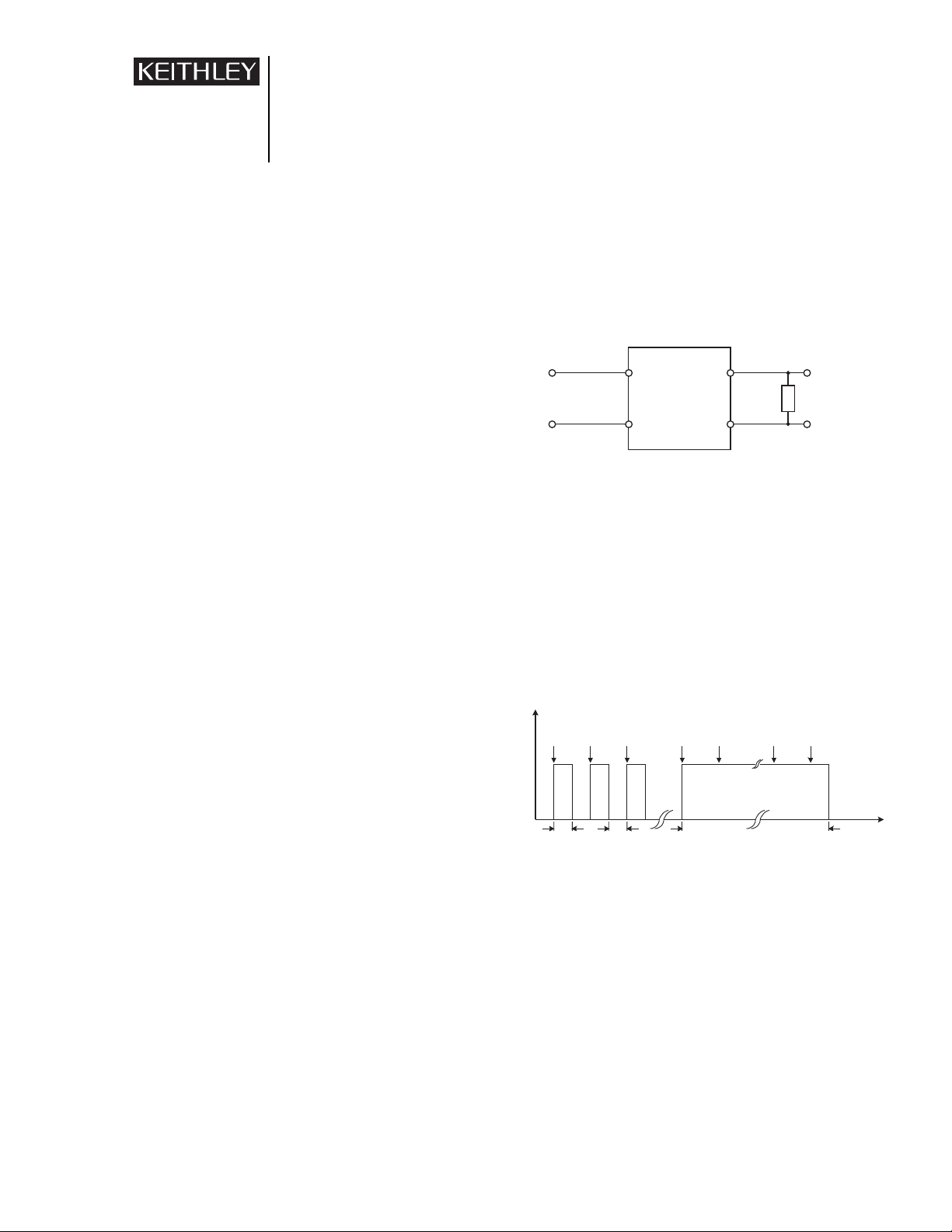
Figure 1 is a simple schematic of a test for monitoring the
voltage output of a power supply. A digital multimeter (DMM)
would be connected in parallel with the load resistance to measure the power supply voltage. The load resistance is chosen to
emulate the load resistances found in the final application, but
may be chosen to reach full output capacity to perform
stress testing.
Figure 1. Monitoring the output of a switching power supply.
Output Cycling
To stress the power supplies being tested further, the output is
repeatedly turned on and off. If a device is destined to fail, the
failure will generally occur when the output is cycled. To capture
failure data, the output voltage of each power supply is measured
during each time the output is turned on, as shown in Figure 2.
After the output is cycled 15 to 20 times, the output is left on
and the power supply is left to continue aging. While the output
is left on, the voltage is measured only occasionally.
Figure 2. Typical burn-in test cycle.
Test System Description
The basic requirement for burn-in testing is to measure the voltage drop across the load resistor placed across the output of each
switching power supply (Figure 1) during the entire test cycle.
Test cycle duration can range from less than an hour to many
days, depending on the quality requirements determined by the
manufacturer.
Figure 3 illustrates an example of an 800-channel burn-in
system in an environmental chamber, using the Model 2000 6
1
⁄
2-
digit DMM to make the required voltage measurement on each
power supply. Two Model 7002 High Density Switching
Application Note
Series
110V or
220V
AC Input
Power Supply
Under Test
Load
R
Monitor
Voltage
(3.3V - 48V)
15–20 Measurements Over Entire Test Cycle
Measure Measure Measure Measure Measure Measure Measure
“ON”
Voltage
“OFF”
Voltage
15 sec
“ON”
15 sec
“OFF”
Repeat 10 Times
40 Minute Constant Output
Time
Page 2
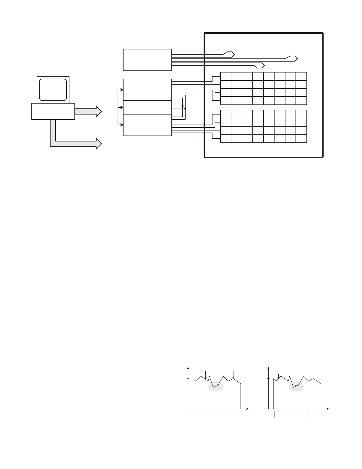
Mainframes are used to connect the inputs of the Model 2000 to
each power supply. Each mainframe can accommodate up to ten
switching cards or 400 channels. The general-purpose Model
7011-C Multiplexer Card is used in this case because each card
can monitor up to 40 channels at 110VDC. Each channel has two
connections (HI and LO) for each power supply.
A typical specification for a power supply is to output 5V
with 10% accuracy, which presents no measurement problem for
a 6
1
⁄2-digit DMM. As shown in Figure 2, when the output is
cycled every 15 seconds, the DMM must make measurements on
800 channels during the 15 second “on” time. Setting the integration rate or measurement time to be as fast as possible (NPLC
= 0.01), disabling all filters, and using the Trigger Link feature
on each instrument makes performing these measurements easy.
The Model 2700 Multimeter/Data Acquisition System is
used to verify the temperature profile of the environmental temperature chamber independently. By plugging two Model 7700
20-channel differential multiplexer modules into the Model
2700, the system can accommodate up to 40 thermocouples. Two
Model 7708 40-channel differential multiplexer modules can
support up to 80 thermocouples.
Methods and Techniques
Synchronization with Trigger Link
The Trigger Link is a hardware handshake bus used by the
instruments in the test system to ensure proper test sequencing. It
is a standard feature on all newer Keithley instruments, including
all instruments mentioned in this application note. When the
meter and switch mainframes are connected via two Model 8501
Trigger Link cables, they can trigger each other to allow faster
test execution. This built-in bus eliminates the need for direct PC
control of most system functions. When the Trigger Link function is used properly, the only functions the PC performs are ini-
tiating the test and retrieving data from the system, leaving synchronization to the instruments themselves.
For more detailed information on how to configure synchronized test systems with Trigger Link, refer to Keithley
Application Note #810, “Optimizing Switch/Read Rates with
Keithley Series 2000 and 7001/7002 Switch Systems.”
Typical Sources of Error
Environmental Noise
Placing hundreds of switching power supplies into an environmental temperature chamber makes it extremely difficult to make
accurate voltage measurements because switching power supplies radiate high frequency noise. If the ground connection is
noisy, traditional data acquisition systems will be unable to make
satisfactory measurements. The system described here requires
scanning across multiple channels rapidly with the high impedance input of the DMM. In this situation, it can be difficult to
distinguish between 5V and 0V on adjacent channels. Even with
the Model 2000’s superior CMRR, NMRR and 22-bit ADC,
making the distinction can be difficult. However, Keithley has
developed an algorithm (described elsewhere in this application
note) that simplifies this problem.
Figure 4a. Good result from multiple Figure 4b. Bad result from multiple
samples. samples.
Model 2700
Figure 3. 800-channel switching power supply burn-in test system schematic.
w/ 7708 Modules
TestPoint
KPCI-488
PIO-32/IO
To All
Instruments
GPIB
Model 7002
w/ 7011 cards
Model 2000
Trigger Link
Model 7002
System Triggering &
Alarm Functions
Digital I/O
w/ 7011 cards
HI
LO
System
Cabling
Environmental Burn-in Chamber
+
Thermocouples
–
+
–
PS PS PS PS PS PS PS PS
PS PS PS PS PS PS PS PS
PS PS PS PS PS PS PS PS
PS PS PS PS PS PS PS PS
PS PS PS PS PS PS PS PS
PS PS PS PS PS PS PS PS
PS PS PS PS PS PS PS PS
PS PS PS PS PS PS PS PS
Power Supplies Under Test
+
–
VOLTAGE
SAMPLE 1 SAMPLE 2
5V
Noise
SAMPLE1 = 4.92V
SAMPLE2 = 5.00V
SAMPLE1 - SAMPLE2 = 0.08V
TIME
VOLTAGE
SAMPLE 1
5V
SAMPLE1 = 5.00V
SAMPLE2 = 4.23V
SAMPLE1 - SAMPLE2 = 0.77V
SAMPLE 2
Noise
TIME
Page 3

To determine whether a power supply is good or bad, the
test system must not only look at the absolute voltage value, but
also at how subsequent readings compare. Figures 4a and 4b
show two different results when sampling a noisy signal.
Assuming the power supply being tested is known to be acceptable, the figures show how noise can affect the final outcome of
the test. Sample 2 in Figure 4b was taken when a noise spike
was introduced into the system. This illustrates the importance of
taking many samples into account from each power supply or
increasing the measurement integration rate.
When measuring 5V on one channel and 0V on the next
with very fast scan speed, a DMM may not measure 0V for the
second channel. Actually, the first reading may be 4.7V and
subsequent readings will decrease to 4.3V, 3.7V and gradually
down to 0V. This gradual decrease id due to the RC time
constant created by the large DMM input impedance and the
capacitance in the test system cabling and fixtures. In contrast,
if the measured 5V (i.e. power supply is good) twice, the two
results will be similar (generally less than 10mV difference).
Therefore, Sample 1 – Sample 2 = Delta, and if Delta is less than
10mV and both samples are within in limits the power supply is
accepted. Without using this algorithm, setting a higher measurement integration rate will significantly improve the instrument’s
measurement performance in noisy environments, but the resulting scan rate would not be sufficient for the number of channels
and time constraints of this application.
Relay Life
Generally, as the power supplies are being tested, their outputs
are turned on. Therefore, as the switch mainframe is scanning
across each device, the relays are being opened and closed with
voltage across their contacts. Actuating a relay in this manner
raises the possibility of arcing, which can severely degrade relay
life. The relays on the Model 7011-C are rated for 10
8
closures
when voltage is not being switched or for 10
5
closures if a 1A,
110V signal is being continually switched. As the signal levels
decrease, the expected life of the relay will increase, so it is
important to note the voltage and current levels of each power
supply that is to be monitored.
Example Program
Using the TestPoint™ application development package,
Keithley has developed an example program to perform a 72channel switching power supply burn-in test that’s similar to the
system shown in Figure 3. To download a copy of the program
(PSBurnIn.tst), visit Keithley’s website at www.keithley.com.
NOTE: The test program provided is intended to illustrate the
concepts presented in this note. Program modifications may be
required to accommodate desired test parameters and timing.
Equipment List
The following equipment is required to assemble the 800channel switching power supply burn-in test system shown in
Figure 3.
• Model 2000 6
1
⁄2-Digit Multimeter.
• Two Model 7002 High Density Switch Mainframes.
• Twenty Model 7011-C Multiplexer Cards.
• Twenty Model 7011-KIT-R 96-pin Female Connect Kit for
constructing custom wiring harness to connect to switching
power supplies.
• Model 2700 Multimeter/Data Acquisition System and Model
7700 Module (20 thermocouple channels per module) or the
Model 7708 Module (40 thermocouple channels per module).
• Model KPCI-488 IEEE-488.2 Interface for the PCI Bus.
• Model PIO-32I/O Isolated 16 Channel Digital Input and 16
Channel Relay Output Board for general system triggering
and alarm functions.
• Three Model 7007 IEEE-488 Interface Cables.
• Two Model 8501 Trigger Link Cables.
• TestPoint software.
Alternative Solutions
The Model 2700 Multimeter/Data Acquisition System supports
up to 80 channels is a nice fit for smaller and more modular systems. The Model 2700 is optimized for smaller HASS systems,
or for smaller production lots of power supplies. The 2700 series
of switch cards many solutions for temperature monitoring and
analog signal routing up to 300V. Output cycling of the power
supplies is accomplished using Keithley's line of PIO digital I/O
boards and solid-state relay (SSR) modules.
Page 4

Specifications are subject to change without notice.
All Keithley trademarks and trade names are the property of Keithley Instruments, Inc. All other
trademarks and trade names are the property of their respective companies.
Keithley Instruments, Inc. 28775 Aurora Road • Cleveland, Ohio 44139 • 440-248-0400 • Fax: 440-248-6168
1-888-KEITHLEY (534-8453) www.keithley.com
BELGIUM: Keithley Instruments B.V. Bergensesteenweg 709 • B-1600 Sint-Pieters-Leeuw • 02/363 00 40 • Fax: 02/363 00 64
CHINA: Keithley Instruments China Yuan Chen Xin Building, Room 705 • 12 Yumin Road, Dewai, Madian • Beijing 100029 • 8610-6202-2886 • Fax: 8610-6202-2892
FRANCE: Keithley Instruments Sarl 3, allée des Garays • 91122 Palaiseau Cédex • 01 64 53 20 20 • Fax: 01 60 11 77 26
GERMANY: Keithley Instruments GmbH Landsberger Strasse 65 • D-82110 Germering • 089/84 93 07-40 • Fax: 089/84 93 07-34
GREAT BRITAIN: Keithley Instruments Ltd. The Minster • 58 Portman Road • Reading, Berkshire RG30 1EA• 0118-9 57 56 66 • Fax: 0118-9 59 64 69
INDIA: Keithley Instruments GmbH Flat 2B, WILLOCRISSA • 14, Rest House Crescent • Bangalore 560 001 • 91-80-509-1320/21 • Fax: 91-80-509-1322
ITALY: Keithley Instruments s.r.l. Viale San Gimignano, 38 • 20146 Milano • 02-48 39 16 01 • Fax: 02-48 30 22 74
KOREA: Keithley Instruments Korea 2FL., URI Building • 2-14 Yangjae-Dong • Seocho-Gu, Seoul 137-130 • 82-2-574-7778 • Fax: 82-2-574-7838
NETHERLANDS: Keithley Instruments B.V. Postbus 559 • NL-4200 AN Gorinchem • 0183-635333 • Fax: 0183-630821
SWITZERLAND: Keithley Instruments SA Kriesbachstrasse 4 • 8600 Dübendorf • 01-821 94 44 • Fax: 01-820 30 81
TAIWAN: Keithley Instruments Taiwan 1FL., 85 Po Ai Street • Hsinchu, Taiwan, R.O.C. • 886-3-572-9077• Fax: 886-3-572-9031
© Copyright 2000 Keithley Instruments, Inc. No. 2260
Printed in the U.S.A. 09005KDCI
Test System Safety
Many electrical test systems or instruments are capable of measuring or sourcing hazardous voltage and power levels. It is also
possible, under single fault conditions (e.g., a programming error
or an instrument failure), to output hazardous levels even when
the system indicates no hazard is present.
These high voltage and power levels make it essential
to protect operators from any of these hazards at all times.
Protection methods include:
• Design test fixtures to prevent operator contact with any
hazardous circuit.
• Make sure the device under test is fully enclosed to protect the
operator from any flying debris. For example, capacitors and
semiconductor devices can explode if too much voltage or
power is applied.
• Double insulate all electrical connections that an operator
could touch. Double insulation ensures the operator is still
protected, even if one insulation layer fails.
• Use high-reliability, fail-safe interlock switches to disconnect
power sources when a test fixture cover is opened.
• Where possible, use automated handlers so operators do not
require access to the inside of the test fixture or have a need
to open guards.
• Provide proper training to all users of the system so they
understand all potential hazards and know how to protect
themselves from injury.
It is the responsibility of the test system designers, integrators, and installers to make sure operator and maintenance
personnel protection is in place and effective.
 Loading...