

Page 1

Model 2000-Scan Scanner Card
A GREATER MEASURE OF CONFIDENCE
Instruction Manual
Page 2

Model 2000-SC AN Scanner Card
Instruction Manual
©1994, Keithley Instruments, Inc.
All rights reserved.
Cleveland, Ohio, U.S.A.
Fifth Printing, July 2003
Document Number: 2000-SCAN-901-01 Rev. E
Page 3

Page 4

Safety Precautions
04/09
The following safety precautions should be observed before using this product and any associated instrumentation.
Although some instruments and accessories would normally be used with non-hazardous voltages, there are
situations where hazardous conditions may be present.
This product is intended for use by qualified personnel who recognize shock hazards and are familiar with the safety
precautions required to avoid possible injury. Read and follow all installation, operation, and maintenance
information carefully before using the product. Refer to the user documentation for complete product specifications.
If the product is used in a manner not specified, the protection provided by the product warranty may be impaired.
The types of product users are:
Responsible body is the individual or group responsible for the use and maintenance of equipment, for ensuring
that the equipment is operated within its specifications and operating limits, and for ensuring that operators are
adequately trained.
Operators use the product for its intended function. They must be trained in electrical safety procedures and proper
use of the instrument. They must be protected from electric shock and contact with hazardous live circuits.
Maintenance personnel perform routine procedures on the product to keep it operating properly, for example,
setting the line voltage or replacing consumable materials. Maintenance procedures are described in the user
documentation. The procedures explicitly state if the operator may perform them. Otherwise, they should be
performed only by service personnel.
Service personnel are trained to work on live circuits, perform safe installations, and repair products. Only properly
trained service personnel may perform installation and service procedures.
Keithley Instruments products are designed for use with electrical signals that are rated Measurement Category I
and Measurement Category II, as described in the International Electrotechnical Commission (IEC) Standard IEC
60664. Most measurement, control, and data I/O signals are Measurement Category I and must not be directly
connected to mains voltage or to voltage sources with high transient over-voltages. Measurement Category II
connections require protection for high transient over-voltages often associated with local AC mains connections.
Assume all measurement, control, and data I/O connections are for connection to Category I sources unless
otherwise marked or described in the user documentation.
Exercise extreme caution when a shock hazard is present. Lethal voltage may be present on cable connector jacks
or test fixtures. The American National Standards Institute (ANSI) states that a shock hazard exists when voltage
levels greater than 30V RMS, 42.4V peak, or 60VDC are present. A good safety practice is to expect that hazardous
voltage is present in any unknown circuit before measuring.
Operators of this product must be protected from electric shock at all times. The responsible body must ensure that
operators are prevented access and/or insulated from every connection point. In some cases, connections must be
exposed to potential human contact. Product operators in these circumstances must be trained to protect
Page 5
themselves from the risk of electric shock. If the circuit is capable of operating at or above 1000V , no conductive part
!
of the circuit may be exposed.
Do not connect switching cards directly to unlimited power circuits. They are intended to be used with impedance-
limited sources. NEVER connect switching cards directly to AC mains. When connecting sources to switching cards,
install protective devices to limit fault current and voltage to the card.
Before operating an instrument, ensure that the line cord is connected to a properly-grounded power receptacle.
Inspect the connecting cables, test leads, and jumpers for possible wear, cracks, or breaks before each use.
When installing equipment where access to the main power cord is restricted, such as rack mounting, a separate
main input power disconnect device must be provided in close proximity to the equipment and within easy reach of
the operator.
For maximum safety, do not touch the product, test cables, or any other instruments while power is applied to the
circuit under test. ALWAYS remove power from the entire test system and discharge any capacitors before:
connecting or disconnecting cables or jumpers, installing or removing switching cards, or making internal changes,
such as installing or removing jumpers.
Do not touch any object that could provide a current path to the common side of the circuit under test or power line
(earth) ground. Always make measurements with dry hands while standing on a dry, insulated surface capable of
withstanding the voltage being measured.
The instrument and accessories must be used in accordance with its specifications and operating instructions, or
the safety of the equipment may be impaired.
Do not exceed the maximum signal levels of the instruments and accessories, as defined in the specifications and
operating information, and as shown on the instrument or test fixture panels, or switching card.
When fuses are used in a product, replace with the same type and rating for continued protection against fire hazard.
Chassis connections must only be used as shield connections for measuring circuits, NOT as safety earth ground
connections.
If you are using a test fixture, keep the lid closed while power is applied to the device under test. Safe operation
requires the use of a lid interlock.
If a screw is present, connect it to safety earth ground using the wire recommended in the user documentation.
The symbol on an instrument means caution, risk of danger. The user should refer to the operating instructions
located in the user documenta ti on in all case s wh ere th e symb ol is ma rked on the instrument.
The symbol on an instrument means caution, risk of danger. Use standard safety precautions to avoid personal
contact with these voltages.
The symbol on an instrument shows that the surface may be hot. Avoid personal contact to prevent burns.
The symbol indicates a connection terminal to the equipment frame.
If this symbol is on a product, it indicates that mercury is present in the display lamp. Please note that the lamp
must be properly disposed of according to federal, state, and local laws.
Page 6

The WARNING heading in the user documentation explains dangers that might result in personal injury or death.
Always read the associated information very carefully before performing the indicated procedure.
The CAUTION heading in the user documentation explains hazards that could damage the instrument. Such
damage may invalidate the warranty.
Instrumentation and accessories shall not be connected to humans.
Before performing any maintenance, disconnect the line cord and all test cables.
To maintain protect ion from electr ic shock a nd fire, replacement components in mains circuits - including the power
transformer, test leads, and input jacks - must be purchased from Keithley Instruments. Standard fuses with
applicable national safety approvals may be used if the rating and type are the same. Other components that are
not safety-related may be purchased from other suppliers as long as they are equivalent to the original component
(note that selected parts should be purchased only through Keithley Instruments to maintain accuracy and
functionality of the product). If you are unsure about the applicability of a replacement component, call a Keithley
Instruments office for information.
T o clean an instrument, use a damp cloth or mild, water-based cleaner . Clean the exterior of the instrument only . Do
not apply cleaner directly to the instrument or allow liquids to enter or spill on the instrument. Products that consist
of a circuit board with no case or chassis (e.g., a data acquisition board for installation into a computer) should never
require cleaning if handled according to instructions. If the board becomes contaminated and operation is affected,
the board should be returned to the factory for proper cleaning/servicing.
Page 7

Table of Contents
1 General Information
Introduction ................................................................................ 1-2
Features ...................................................................................... 1-2
Manual addenda ......................................................................... 1-3
Safety symbols and terms .................................. ........................ 1-3
Specifications ............................................................................. 1-3
Unpacking and inspection .......................................................... 1-4
Inspection for damage ......................................................... 1-4
Handling precautions .......................................................... 1-4
Shipment contents .................................. ............................. 1-4
Instruction manual .............................................................. 1-4
Repacking for shipment ............................................................. 1-4
2 Card Connections and Installation
Introduction ................................................................................ 2-2
Handling precautions ................................................................. 2-2
Connections ................................................................................ 2-3
Connection precautions ....................................................... 2-3
Card configuration ................................... ... ........................ 2-4
Card connectors .................................................................. 2-5
Wiring procedure ................................................................ 2-6
Output connections ............................................................. 2-7
Dressing leads ..................................................................... 2-8
Typical connecting schemes ...................................................... 2-9
Voltage connections ............................................................ 2-9
Resistance connections ..................................................... 2-10
Current measurements ...................................................... 2-12
Card installation and removal .................................................. 2-15
Scanner Card Installation .................................................. 2-16
Output connections to multimeter ..................................... 2-17
Scanner card removal ........................................................ 2-18
3 Operation
Introduction ................................................................................ 3-2
Signal limitations ....................................................................... 3-3
Relay input signal limitations ............................................. 3-3
Scanner card detection ............................................................... 3-3
Power-up detection ............................................................. 3-3
Scanner option bus query .................................................... 3-3
Page 8

Model 2000 Multimeter front panel scanner controls and SCPI scanner commands 3-
4
Closing channels ................................................................. 3-4
Opening channels ................................ ................................ 3-4
Selecting measurement function ......................................... 3-5
Configuring scan parameters ............................................... 3-5
SCPI scanner commands .............................. .............................. 3-7
Model 2001/2002 front panel scanner controls and ................... 3-8
SCPI scanner commands .............................. .............................. 3-8
Closing channels ................................................................. 3-8
Opening channels ................................ ................................ 3-9
Scanning channels ............................................................. 3-10
Using the scanner with the buffer ..................................... 3-13
RTD temperature measurements .............................................. 3-14
Typical applications .................................................................. 3-16
Resistor testing .................................................................. 3-16
Current measurements ....................................................... 3-19
Measurement considerations .................................................... 3-20
Path isolation ..................................................................... 3-20
Magnetic fields .................................................................. 3-21
Electromagnetic interference (EMI) .................................. 3-21
Ground loops ..................................................................... 3-22
Keeping connectors clean .................................................. 3-23
4 Service Information
Introduction ................................................................................ 4-2
Handling and cleaning precautions ............................................ 4-2
Handling precautions ........................................................... 4-2
Soldering precautions .......................................................... 4-3
Performance verification ............................................................ 4-3
Environmental conditions ................................................... 4-3
Recommended equipment ................................................... 4-4
Scanner card connections .................................................... 4-4
Path resistance tests ............................................................. 4-4
Contact potential tests ......................................................... 4-6
Isolation tests ....................................................................... 4-8
Special handling of static-sensitive devices ............................. 4-11
Principles of operation .............................................................. 4-11
Block diagram ................................................................... 4-11
Relay control ..................................................................... 4-12
Switching circuits .............................................................. 4-12
Power-on safeguard .................................. ......................... 4-12
Troubleshooting ........................................................................ 4-13
Troubleshooting equipment ............................................... 4-13
Page 9

Troubleshooting access ..................................................... 4-13
Troubleshooting procedure ............................................... 4-14
5 Replaceable Parts
Introduction ................................................................................ 5-2
Parts list ...................................................................................... 5-2
Ordering information ................................................................. 5-2
Factory service ..................................... ...................................... 5-2
Component layout and schematic diagram ................................ 5-3
Table of Contents ....................................................................... 1-1
List of Illustrations ..................................................................... 1-4
List of Tables ............................................................................. 1-5
Index ........................................................................................... 1-1
Page 10

Page 11

General
Information
1
General
Information
Page 12

1-2 General Information
Introduction
This section contains general information about the Model 2000-SCAN scanner card. The
Model 2000-SCAN provides 10 channels of 2-pole relay switching. The channels can be configured for 4-pole operation.
Section 1 is arranged in the following manner:
Features
Manual addenda
Safety symbols and terms
Specifications
Unpacking and inspection
Repacking for shipment
Featur es
The Model 2000-SCAN is a scanner card designed to be installed in the Model 2000 Multimeter, Model 2001 Multimeter, and Model 2002 Multimeter.
Key features include:
• T en channels of 2-pole relay input.
• Channels configurable for 4-pole operation.
• Multiplex one of ten 2-pole, or one of five 4-pole channels into a Model 2000/2001/2002
Multimeter.
Page 13
Manual addenda
!
Any improvements or changes concerning the scanner card or manual will be explained in an
addendum included with the card. Addenda are provided in a page replacement format. Simply
replace the obsolete pages with the new pages.
Safety symbols and terms
The following symbols and terms may be found on an instrument or used in this manual.
The symbol on an instrument indicates that the user should refer to the operating
instructions located in the instruction manual.
The symbol on an instrument shows that high voltage may be present on the terminal(s).
Use standard safety precautions to avoid personal contact with these voltages.
The WARNING heading used in this manual explains dangers that might result in personal
injury or death. Always read the associated information very carefully before performing the
indicated procedure.
1-3
The CAUTION heading used in this manual explains hazards that could damage the scanner
card. Such damage may invalidate the warranty.
Specifications
Model 2000-SCAN specifications are found in Appendix A. These specifications are exclusive of the multimeter specifications.
Page 14

1-4 General Information
Unpacking and inspection
Inspection for damage
The Model 2000-SCAN is packaged in a re-sealable, anti-static bag to protect it from damage
due to static discharge and from contamination that could degrade its performance. Before
removing the card from the bag, observe the precautions below on handling.
Handling precautions
• Always grasp the card by the side edges and covers. Do not touch the board surfaces or
components.
• When the card is not installed in a multimeter, keep the card in the anti-static bag, and
store it in the original packing carton. After removing the card from its anti-static bag,
inspect it for any obvious signs of physical damage. Report any such damage to the shipping agent immediately.
Shipment contents
The following items are included with every Model 2000-SCAN order:
• Model 2000-SCAN Scanner Card
• Model 2000-SCAN Instruction Manual
• CA-109 test lead set for output connections (two red, two black)
• Additional accessories as ordered
Instruction manual
If an additional Model 2000-SCAN Instruction Manual is required, order the manual package, Keithley part number 2000-SCAN-901-00. The manual package includes an instruction
manual and any pertinent addenda.
Repacking for shipment
Should it become necessary to return the Model 2000-SCAN for repair, carefully pack the
unit in its original packing carton or the equivalent, and include the following information:
• Advise as to the warranty status of the scanner card.
• Write ATTENTION REPAIR DEPARTMENT on the shipping label.
• Fill out and include the service form located at the back of this manual.
Page 15

Card Connec-
tions and Instal-
lation
2
Card Connections
and Installation
Page 16

2-2 Card Connections and Installation
Introduction
WARNING The procedures in this section are intended only for qualified service
personnel. Do not perform these procedures unless you are qualified to do so.
Failure to recognize and observe normal safety precautions could result in
personal injury or death.
This section includes information on making connections to the Model 2000-SCAN and on
installing the card in a Model 2000/2001/2002 Multimeter. This section is arranged as follows:
Handling precautions — Explains precautions that must be followed to prevent
contamination to the scanner card assembly. Contamination could degrade the performance of
the scanner card.
Connections — Covers the basics for connecting external circuitry to the scanner card.
Typical connection schemes — Provides some typical connection schemes for 2-pole and
4-pole operation.
Card installation and removal — Summarizes the procedure to install the scanner card in a
multimeter, outlines scanner card output connections, and describes how to remove the card.
Handling precautions
T o maintain high impedance isolation between channels, care should be taken when handling
the scanner card to avoid contamination from such foreign materials as body oils. Such
contamination can substantially lower leakage resistances, degrading card performance. To
avoid possible contamination, always grasp the scanner card by the side edges or cov ers. Do not
touch board surfaces, components, or areas adjacent to electrical contacts.
Dirt build-up over a period of time is another possible source of contamination. To av oid this
problem, operate the multimeter and scanner card in a clean environment. If the card becomes
contaminated, it should be thoroughly cleaned as explained in Section 4 “Handling and cleaning
precautions”.
Page 17

Connections
This paragraph provides the information necessary to connect your external test circuitry to
the scanner card.
NOTE All connecting wires or leads must be connected to the card before it is installed in a
Connection precautions
W ARNING Connection information for the Model 2000-SCAN is intended for qualified
Card Connections and Installation 2-3
multimeter.
service personnel. Do not attempt to connect the DUT or external circuitry
to a scanner card unless qualified to do so.
T o prevent electric shock that could result in serious injury or death, adhere
to the following safety precautions:
• Before making or breaking connections to the scanner card, make sure
the DMM power is turned off and power is removed from all external
circuitry.
• Do not connect signals that will exceed the maximum specifications of the
scanner card.
If both the front panel terminals and the scanner card terminals are
connected at the same time, the maximum signal ratings of the front panel
terminals are reduced to the maximum signal ratings of the scanner card.
As described in the International Electrotechnical Commission (IEC)
Standard IEC 664, scanner cards are Installation Category I and must not
be connected to mains.
Page 18
HI
LO
Channel 1
HI
LO
Channel 2-4
Channel 5
HI
LO
Channel 6
HI
LO
Channel 7-9
Channel 10
HI
LO
OUT A
(To DMM input jacks)
OUT B
(To DMM sense jacks)
HI
LO
2-Pole4-Pole
User-installed
current shunt
User-installed
current shunt
Figure 2-1
Model 2000-SCAN
simplified schematic
2-4 Card Connections and Installation
Card configur ation
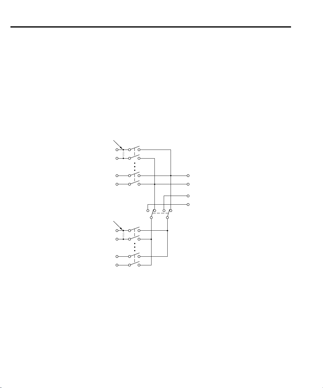
Figure 2-1 shows a simplified schematic diagram of the Model 2000-SCAN. The scanner
card has ten input channels and two outputs. Channels 1-10 are all switched by relays.
4-pole paired channels are as follows:
• Channels 1 and 6
• Channels 2 and 7
• Channels 3 and 8
• Channels 4 and 9
• Channels 5 and 10
Page 19
CH 1HLCH 2HLCH 3HLCH 4HLCH 5
HL
OUT A
HL
CH 6
HL
CH 7HLCH 8HLCH 9HLCH 10
HL
OUT B
HL
Channels 1-5, OUT A Channels 6-10, OUT B
Locking Tab
Plastic Shield
Figure 2-2
Card connectors
Card Connections and Installation 2-5
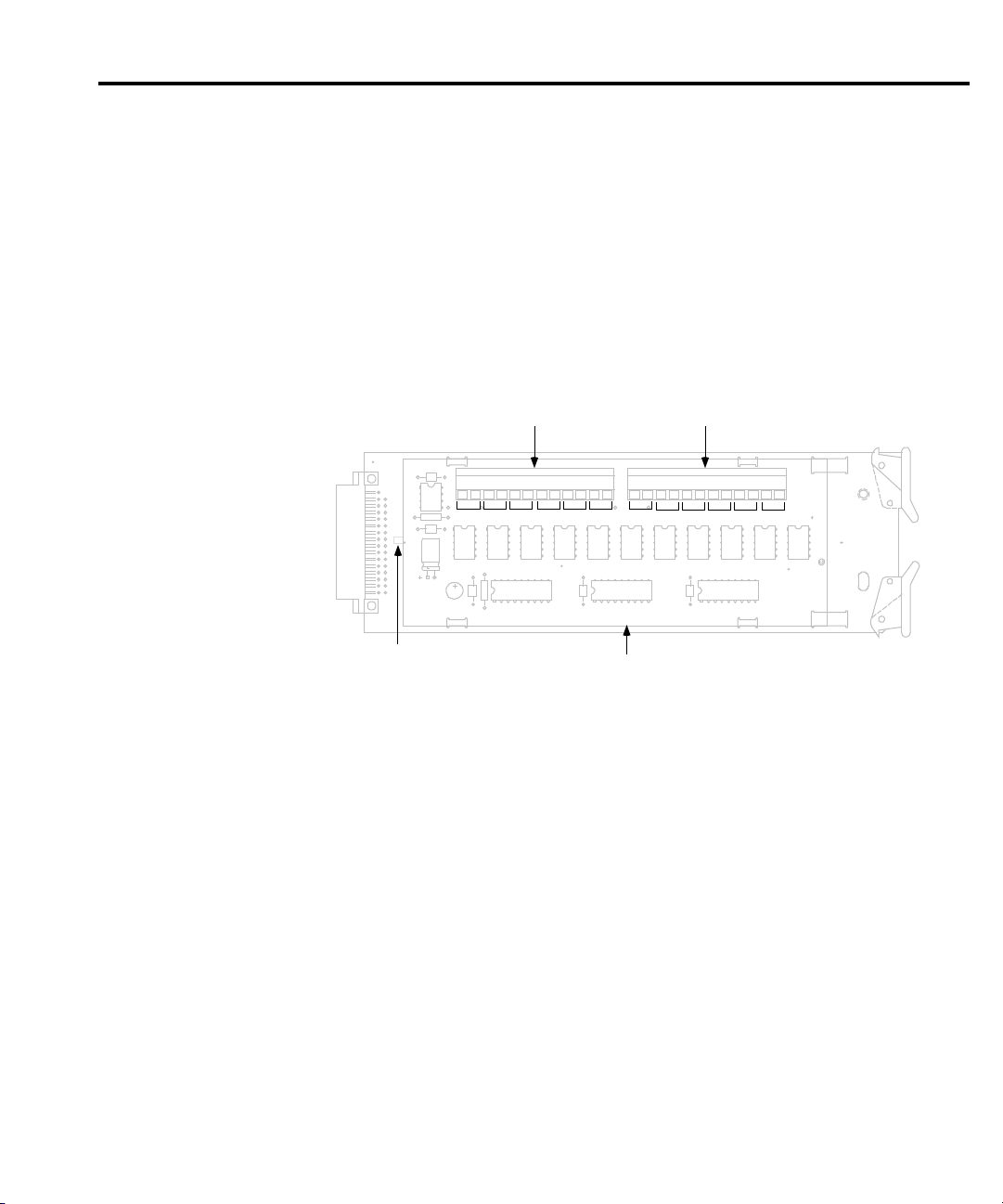
Figure 2-2 shows the input/output connectors for the card. Card connections include:
• CH 1-10 (channels 1-10): HI and LO input terminals are provided for each of the 10
channels on the card.
• OUT A: HI and LO output connections for all ten channels in the 2-pole mode or
channels 1-5 in the 4-pole mode.
• OUT B: HI and LO output connections for channels 6-10 in the 4-pole mode.
In order to gain access to the connections, first open the plastic shield by pressing in on the
locking tab. Swing the shield away from the circuit board.
Page 20

2-6 Card Connections and Installation
Wiring procedur e
Perform the following procedure to wire circuitry to the screw terminals on the scanner card.
WARNING Make sure all power is off and any stored energy in external circuitry is
discharged before connecting or disconnecting wires.
CAUTION Mechanical shock may open or close latching relays on the scanner card.
Before enabling any external sources, open all relays by inserting the
Model 2000-SCAN into the multimeter and turning on the power.
1. Open the plastic shield to gain access to the connectors.
2. Strip approximately 5/16” of insulation from the end of each wire, then twist the strands
together.
NOTE #22 AWG stranded wire is recommended for scanner card connections.
3. Loosen the screw terminal, then insert the wire into the access hole.
4. While holding the wire in place, tighten the connector screw securely.
5. Repeat steps 1 through 3 for each wire to be connected.
6. Dress input wires through the cable clamp, as discussed in “Dressing leads” on page 2-8.
Page 21
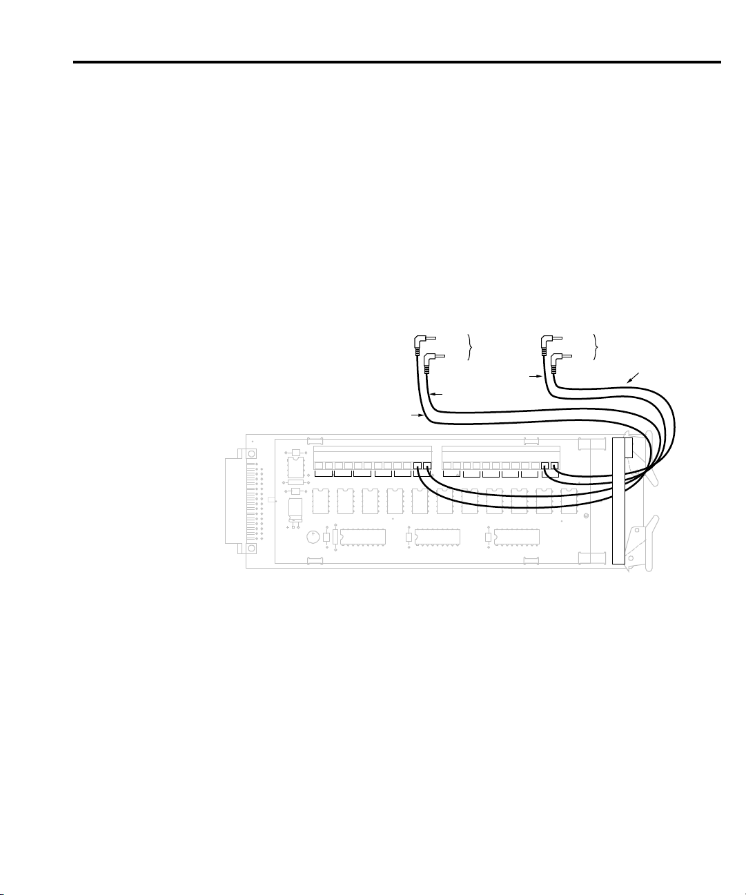
Output connections
CH 1HLCH 2HLCH 3HLCH 4HLCH 5
HL
OUT A
HL
CH 6
HL
CH 7HLCH 8HLCH 9HLCH 10
HL
OUT B
HL
HI
LO
To DMM
Input
Red
Black
HI
Red
Black
To DMM
Sense
Note: OUT B connections not required
for 2-pole operation. Plastic shield
not shown.
LO
Figure 2-3
Output connections
Use the supplied test leads for scanner output connections. Connect red leads to the output
(OUT A and OUT B) HI terminals, and connect black leads to the output LO terminals. See
Figure 2-3 for details. Dress output test leads through the cable clamp, as described in “Dressing
leads” on page 2-8. After all wires are connected and secure, close the plastic shield, and secure
it with the locking tab.
NOTE If you intend to use the scanner card only in the 2-pole mode, it is not necessary to
connect output leads to both OUT A and OUT B. Use only OUT A for the 2-pole mode.
After the scanner card is installed, the output leads must be connected to the multimeter rear
panel input jacks. See “Output connections to multimeter” on page 2-17 for details.
Card Connections and Installation 2-7
Page 22
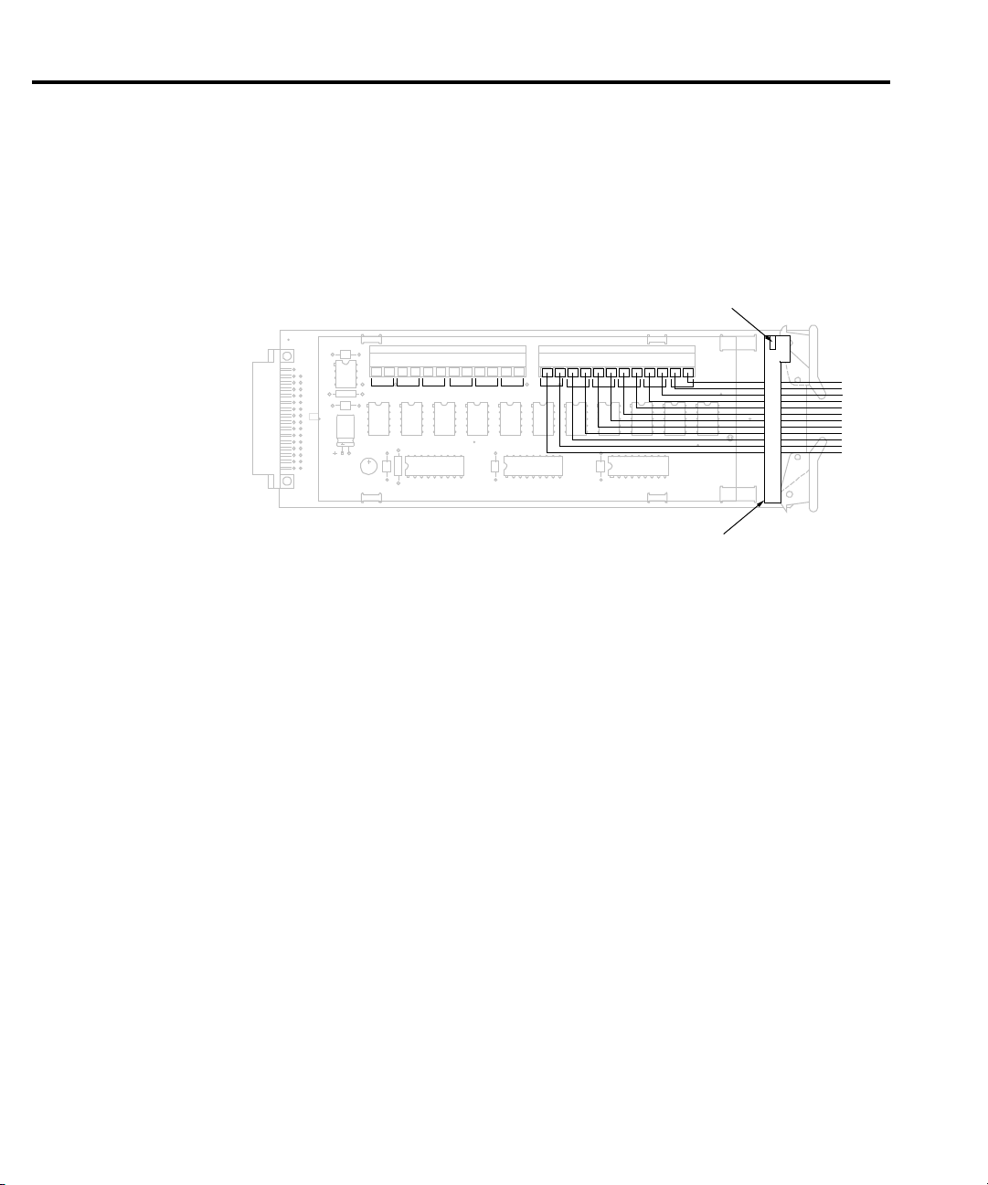
CH 1HLCH 2HLCH 3HLCH 4HLCH 5
HL
OUT A
HL
CH 6
HL
CH 7HLCH 8HLCH 9HLCH 10
HL
OUT B
HL
Cable Clamp
Note : Plastic shield not shown.
Metal Clip
Figure 2-4
Routing wires through
cable clamp
2-8 Card Connections and Installation
Dressing leads
After wires are connected to the terminal blocks, they should be dressed through the cable
clamp as shown in Figure 2-4. To do so, unlatch the clip that holds the cable clamp together , then
route all wires flat against the lower half of the clamp. Clamp the wires down, then secure the
clamp with the metal clip unlatched earlier.
Page 23
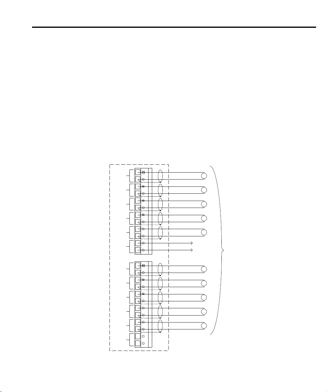
Typical connecting schemes
H L H L H L H L H L H L H L H L H L H L H LHL
CH 1
CH 2
CH 3
CH 4
CH 5
OUT A
CH 6
CH 7
CH 8
CH 9
CH 10
OUT B
V
HI
LO
V
HI
LO
V
HI
LO
V
HI
LO
V
HI
LO
To DMM
Input
HI
LO
V
HI
LO
V
HI
LO
V
HI
LO
V
HI
LO
V
HI
LO
2000-SCAN Card
Voltages
Under Test
Figure 2-5
Connections for voltage
scanning
The following paragraphs discuss typical connections for the scanner card.
V oltage connections
Figure 2-5 shows typical connections for voltage measurements. Note that all channels are
used in the 2-pole mode, and that up to 10 voltage sources can be switched with this
configuration. This basic configuration can be used for the following types of measurements:
•DCV
•ACV
• Frequency (voltage only)
All channels (1-10) can be used with this configuration.
Card Connections and Installation 2-9
Page 24
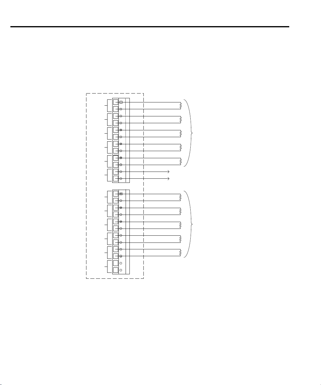
H L
H
H L H L H L H L H
L
H L H L H
L
H LHL
CH 1
CH 2
CH 3
CH 4
CH 5
OUT A
CH 6
CH 7
CH 8
CH 9
CH 10
OUT B
To DMM
Input
2000-SCAN Card
Resistors
Under Test
Resistors
Under Test
HI
LO
L
Figure 2-6
Typical connections
for 2-wire resistance
scanning
2-10 Card Connections and Installation
Resistance connections
2-Pole connections
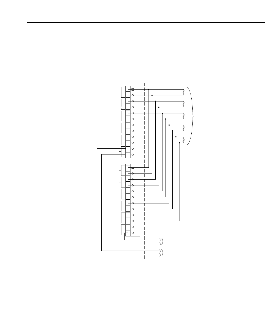
Figure 2-6 shows typical 2-pole resistor test connections. The 2-pole resistance configuration
can be used to test up to ten DUTs.
Page 25
H L H
L
H L H L H L H L H L H L H L H L H LHL
CH 1
CH 2
CH 3
CH 4
CH 5
OUT A
CH 6
CH 7
CH 8
CH 9
CH 10
OUT B
To DMM Sense
2000-SCAN Card
Resistors
Under Test
To DMM Input
HI
LO
HI
LO
Figure 2-7
Typical connections
for 4-wire resistance
scanning
Card Connections and Installation 2-11
4-Pole connections
T ypical 4-pole resistance connections are shown in Figure 2-7. This general configuration can
be used with all channels to scan:
• 4-wire resistance measurements.
• 4-wire RTD temperature measurements (Model 2001 and 2002 multimeters).
Page 26
R145 (Channel 1 shunt)
R146 (Channel 6 shunt)
CH 1HLCH 2HLCH 3HLCH 4HLCH 5
HL
OUT A
HL
CH 6
HL
CH 7HLCH 8HLCH 9HLCH 10
HL
OUT B
HL
Figure 2-8
Current shunt locations
2-12 Card Connections and Installation
Current measurements
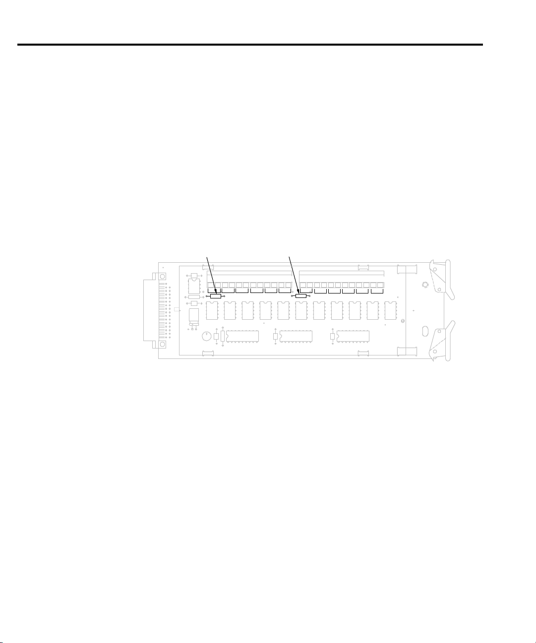
Current shunts can be installed on the circuit board to allow indirect AC and DC current
measurements to be made through channels 1 and 6 only. The following paragraphs discuss
installing current shunts and the basic methods used to determine currents.
CAUTION Board mounted current shunt resistors can be installed only for channels 1
and 6. A channel that has been modified with a current shunt resistor should
not be used for voltage or resistance measurements.
Current shunt locations
Figure 2-8 shows the locations for the user-installable current shunts. Location R145 is for
channel 1 and R146 is for channel 6.
Recommended current shunt values
Hole spacing on the circuit board is intended for 1/4W resistors. The resistance value will
depend on the current you intend to measure; 1k¾ resistors should be optimum for many
applications. A 1k¾ resistor will allow you to switch currents up to 15mA without exceeding
the power rating of the resistor.
For larger currents, decrease the shunt value. Con versely , the shunt v alue can be increased for
smaller currents.
CAUTION Do not exceed the maximum card signal levels:
• DC signals: 110V DC, 1A switched, 30 VA maximum.
• AC signals: 125V AC rms or 175V AC peak, 1A switched, 62.5 VA
maximum.
Page 27

Card Connections and Installation 2-13
Board cleaning
NOTE F ailure to observe the following precautions may result in degraded card
performance.
When soldering resistors, be sure not to touch areas not associated with resistor installation
or spread flux around to other areas of the circuit board. Use solder with an OA (organic
activated) flux. The circuit board should be thoroughly cleaned with pure water after soldering
to remove all contaminants. After cleaning with water, swab the area with pure methanol, then
allow the board to dry for several hours in a 50°C environment before use.
Current measurements
Even with the current shunts installed, you cannot make direct current measurements with the
scanner card. Instead, you must close the channel to be measured, and measure the voltage
across the shunt. The current can then be calculated as follows:
Where: I = current being determined
V= voltage measured by multimeter
R= shunt resistance value
Instead of manually calculating current, set up a Model 2000/2001/2002 mX + b math
calculation function. (Here, m = 1/R and b = 0.). The multimeter will then display the actual
current value. Refer to the multimeter manuals for details on using math functions.
Page 28
H L
H L H L
H
L H L
H L
H L H L H L H L H LHL
CH 1
CH 2
CH 3
CH 4
CH 5
OUT A
CH 6
CH 7
CH 8
CH 9
CH 10
OUT B
2000-SCAN Card
AC or DC
Current
A
AC or DC
Current
A
Note: Current shunts must be
installed for channels
1 and 6.
To DMM
Input
Figure 2-9
Current connections
2-14 Card Connections and Installation
Current connections
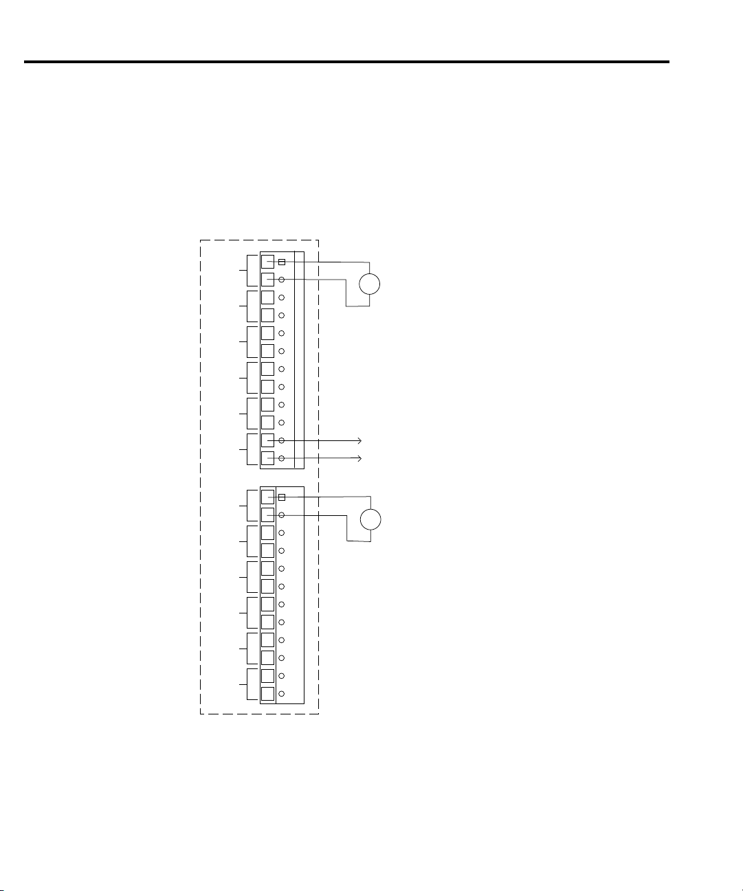
Figure 2-9 shows typical connections for measuring currents using the Model 2000-SCAN
with current shunts installed. As noted previously , only channels 1 and 6 have current shunts
installed, and this configuration can be used to scan the following:
• DC current
•AC current
Page 29

Card installation and remo val
This paragraph explains how to install and remove the Model 2000-SCAN card assembly
from the Model 2000 Multimeter.
WARNING Installation or removal of the Model 2000-SCAN should be performed only
by qualified service personnel. Failure to recognize and observe standard
safety precautions could result in personal injury or death.
NOTE To prevent contamination to the scanner card that could degrade performance,
handle the card assembly only by the card edges and covers.
Wiring connections must made before installing the scanner card. See “Typical
connecting schemes” on page 2-9 for wiring details.
Card Connections and Installation 2-15
Page 30
Ejector Arms (2)
Unlock card
Lock card
Note: Card installation in a Model 2001/2002
is shown. For installation in Model 2000,
turn card over.
Figure 2-10
Card installation
2-16 Card Connections and Installation
Scanner Card Installation
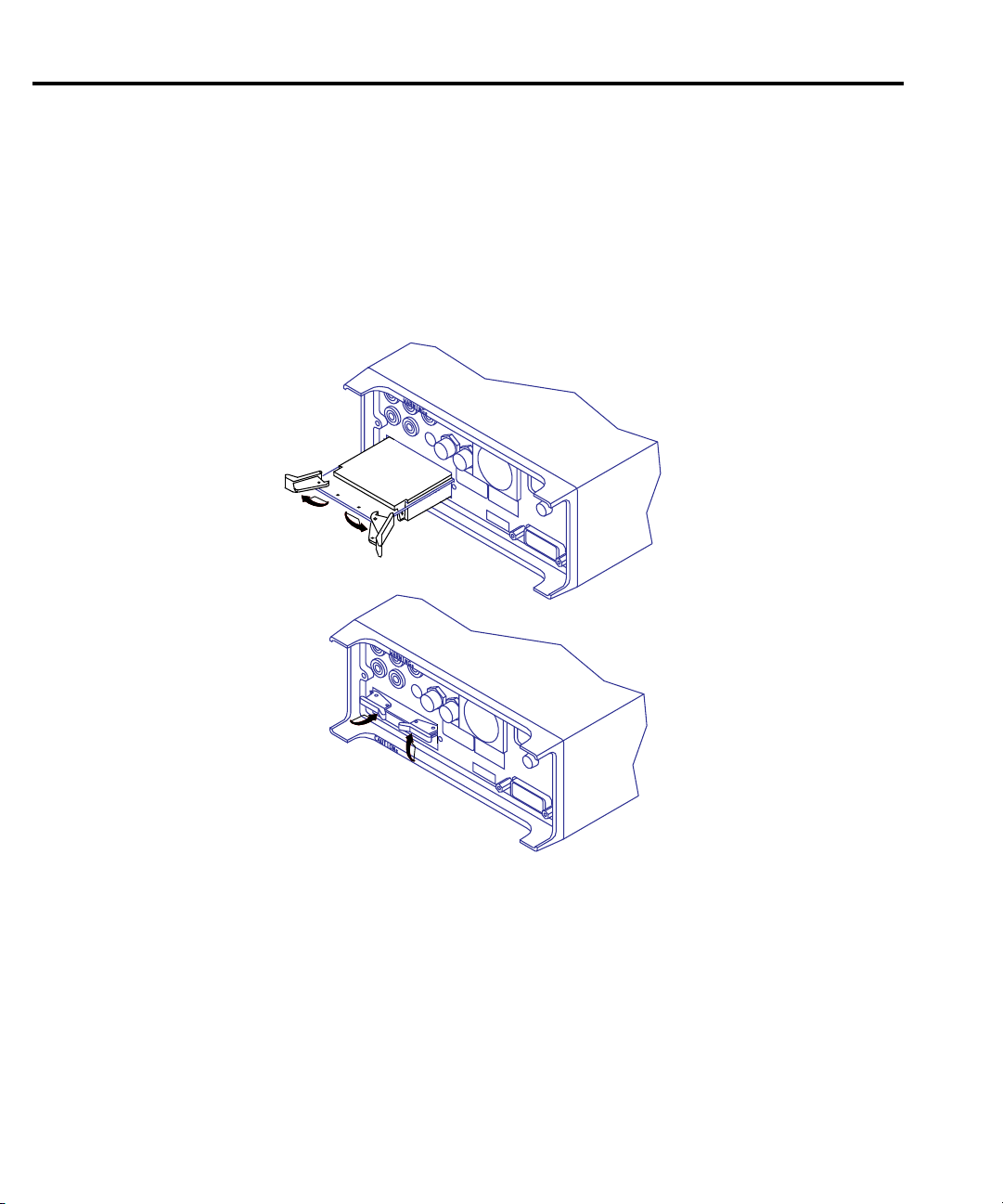
Perform the following steps and refer to Figure 2-10 to install the card assembly in the
multimeter:
WARNING Turn off power to all instrumentation (including the multimeter) and
disconnect all line cords. Make sure all power is removed and any stored
energy in external circuitry is discharged.
1. Remove the cover plate from the OPTION SLO T on the rear panel of the multimeter . To
Do so, pry out the two fasteners, then remove the Cover plate.
2. Slide the card edges into the guide rails inside the multimeter (solder side up for
Model 2001/2002, component side up for Model 2000).
3. With the ejector arms in the unlocked position, carefully push the card all the way
forward until the arms engage the ejector clips. Push both arms inward to lock the card
into the multimeter.
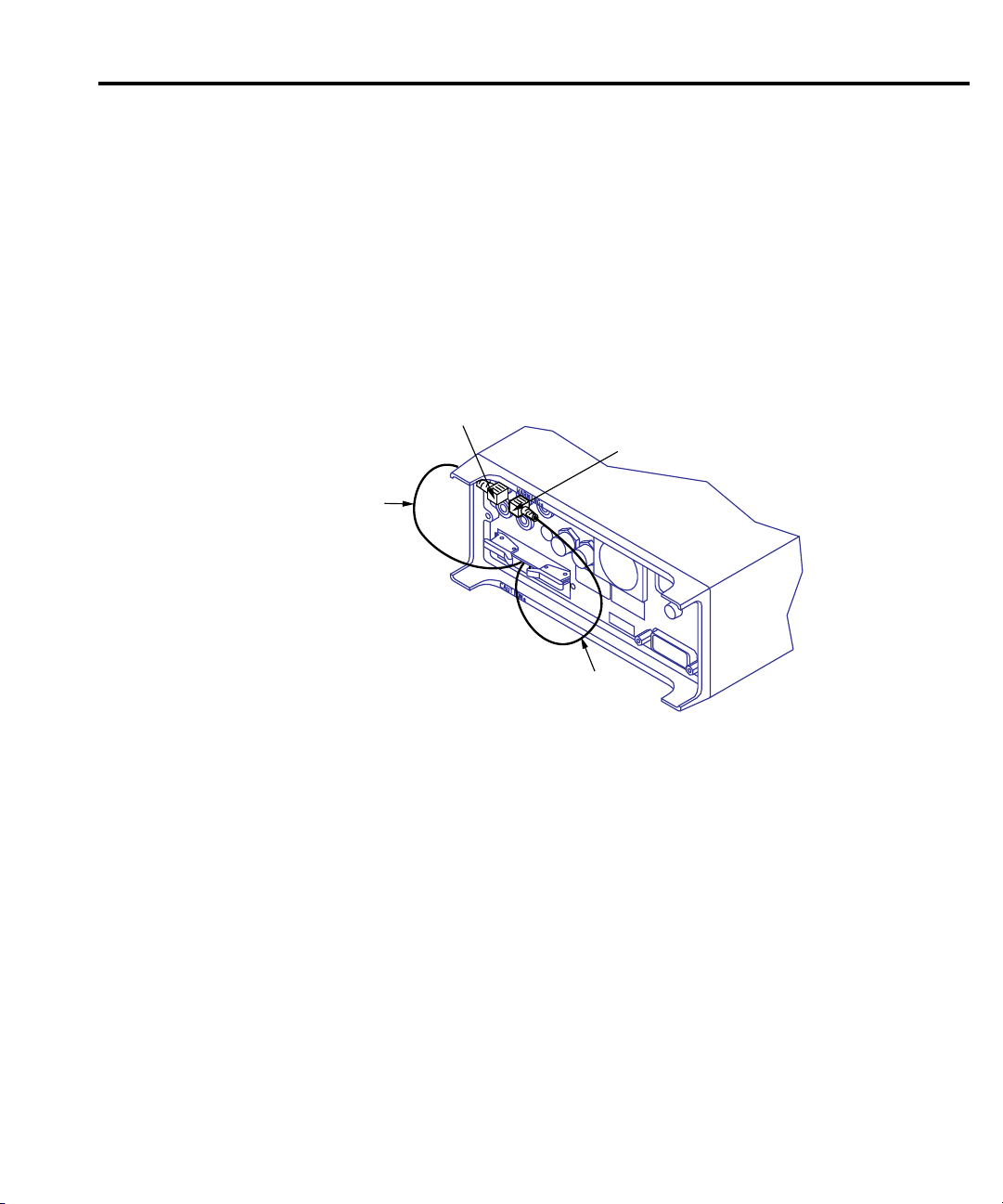
4. After installation, connect the output leads to the multimeter as discussed below.
Page 31
Output connections to multimeter
Input HI
Out A
HI (Red)
Input LO
Out A
LO (Black)
Note: Card installation in a Model 2001/2002
is shown. For installation in Model 2000,
turn card over.
Figure 2-11
2-pole output
connections
After installation, connect the scanner card output leads to the multimeter rear panel jacks as
follows:
WARNING Signals applied to the front inputs of the multimeter cannot exceed ratings
of the scanner card as long as the scanner card output leads are connected
to the multimeter rear panel input jacks.
• For 2-pole operation, connect OUT A HI (red) to INPUT HI, and connect OUT A LO
(black) to INPUT LO. See Figure 2-11.
Card Connections and Installation 2-17
NOTE Be sure to select the rear inputs with the multimeter fr ont panel INPUTS switch when
using the scanner.
Page 32
Input HI
Out A
HI (Red)
Input LO
Out A
LO (Black)
Out B
HI (Red)
Sense HI
Sense LO
Out B
LO (Black)
Note: Card installation in a Model 2001/2002
is shown. For installation in Model 2000,
turn card over.
Figure 2-12
4-pole output
connections
2-18 Card Connections and Installation
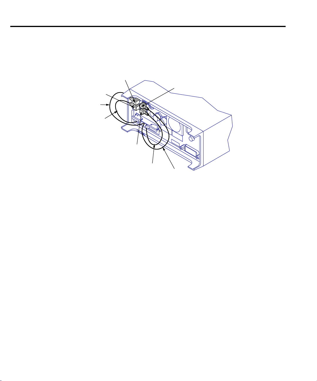
• For 4-pole operation, connect OUT A HI (red) to INPUT HI, and connect OUT A LO
(black) to INPUT LO. Also connect OUT B HI (red) to SENSE HI, and connect OUT B
LO (black) to SENSE LO. See Figure 2-12.
Scanner card remo val
Follow the steps below to remove the scanner card from the multimeter:
WARNING Turn off power to all instrumentation (including the multimeter) and
1. Unlock the card by pulling the latches outward.
2. Carefully slide the card out of the multimeter.
3. If the multimeter is to be operated without the scanner card installed, install the cover
plate over the OPTION SLOT.
disconnect all line cords. Make sure all power is removed and any stored
energy in external circuitry is discharged.
Page 33

Operation
3
Operation
Page 34

3-2 Operation
Introduction
This section contains detailed information on front panel and IEEE-488 bus operation of the
Model 2000-SCAN. The information in this section is organized as follows:
Signal limitations — Summarizes the maximum signals that can be applied to the
Model 2000-SCAN.
Scanner card detection — Discusses how the scanner card is detected and how to determine
whether or not the card is installed with a bus command.
Model 2000 front panel scanner controls and IEEE-488 bus scanner commands — Gives
an overview of the Model 2000 Multimeter front panel controls and corresponding IEEE-488
bus commands used to control the scanner card.
IEEE-488 bus scanner commands — Summarizes bus commands necessary to control the
scanner card by either the Model 2000 or Model 2001/2002 Multimeters.
Model 2001/2002 front panel scanner controls and IEEE-488 bus scanner commands —
Gives and overvie w of the Model 2001/2002 Multimeter front panel controls and corresponding
IEEE-488 bus commands used to control the scanner card.
RTD temperature measurements — Provides detailed information on using RTD probes
when scanning (Model 2001/2002).
Typical applications — Discusses typical applications for the Model 2000-SCAN.
Measurement considerations — Discusses a number of measurement considerations that
should be taken into account when using the scanner.
NOTE Before using the Model 2000-SCAN scanner card, you should be thoroughly
familiar with the operation of the Model 2000 /2001/2002 Multimeter. See the
multimeter manual for details.
Page 35

Signal limitations
CAUTION To prevent damage to the Model 2000-SCAN, do not exceed the maximum
signal level specifications of the card.
Relay input signal limitations
Channels 1-10 are all relay inputs. To prevent over-heating or damage to the relays, never
exceed the following maximum signal levels for these channels:
DC signals: 110V DC, 1A switched, 30VA (resistive load).
AC signals: 125V rms or 175V AC peak, 1A switched, 62.5VA (resistive load).
Scanner card detection
Po wer -up detection
The scanner card is detected only at power-on. If the card is plugged in after the power is
turned on, the card will not be recognized as being present by the multimeter.
Operation 3-3
CAUTION Plugging in the scanner card with power turned on may result in damage to
both the Model 2000-SCAN and the multimeter.
If the card is not present at power-on, scanner bus commands or queries will generate a
“Missing hardware error”, and front panel operations pertaining to the scanner will inform you
that no scanner is present.
Scanner option bus query
*OPT? is an IEEE 488.2 common query which will allow you determine whether or not a
scanner card is installed. The response to this query indicates whether or not a scanner card is
present as follows:
• 0: Scanner not installed.
• 200X-SCAN: Scanner installed. (The Model 2000 does not distinguish among scanner
cards.)
Refer to Model 2000/2001/2002 manuals for more details on using the *OPT? query.
Page 36

Model 2000 Multimeter front panel scanner contr ols and SCPI scanner commands
The following paragraphs give an ov erview of the various Model 2000 Multimeter front panel
controls and corresponding SCPI commands used with the Model 2000-SCAN.
Closing channels
Front P anel
Use the front panel CLOSE key to close specific channels as follows:
1. From the normal display, press the CLOSE key. The instrument will display the
following:
CLOSE CHAN: 01
2. Use the , , ▲ and ▼ keys to select the channel you wish to close, then press
ENTER.
The number of the closed channel will be displayed on the front panel along with normal
readings. Selecting a different channel from the one presently closed will cause the
closed channel to open and allow a settling time before closing the selected channel.
3. The and keys alone will also close the channels. Press the and keys until
the channel annunciator you wish closed appears on the display.
Remote interface
Use the :ROUTe:CLOSe command to close the desired channel. For example, if you wish to
close channel 4, use the following command:
PRINT #1, "output 16; :route:close (@4)"
Use the :ROUT e:MULTiple:CLOSe command to close multiple channel. For example, if you
wish to close channels 1, 3 and 5, use the following command:
PRINT #1, "output 16; :route:multiple:close (@1,3,5)"
Note that opening channel 11 selects the 4-pole operating mode.
Opening channels
Front P anel
Use the front panel OPEN key to open all of the card channels.
Page 37

Remote interface
Use the :ROUTe:OPEN:ALL command to open all of the channels. The command is as
follows:
PRINT #1, "output 16; :route:open:all"
Use the :ROUT e:MUL T iple:OPEN command to open specified channels. For example, if you
wish to open channels 1, 3 and 5, use the following command:
PRINT #1, "output 16; :route:multiple:open (@1,3,5)"
Note that opening channel 11 selects the 2-pole operating mode.
Selecting measurement function
This section describes how to select a specific measurement function for an internal channel.
1. Use the and keys to select the desired channel.
2. Select the desired measurement function with the keys on the front panel. The various
measurement functions available are:
DCV: DC volts PERIOD: period
ACV: AC volts TEMP: simulated temperature
¾2W: 2-wire ohms CONT: continuity
¾4W: 4-wire ohms (channels 1-5) : diode test
FREQ: frequency
Configuring scan parameters
This section details how to select internal scanning and how to configure the scan parameters.
Front P anel
Use the SHIFT-CONFIG keys to select the scan type and configure the scan parameters.
1. Press SHIFT then CONFIG. The instrument will display the following prompt for
internal scanning:
TYPE: INT
Use the ▲ or ▼ key if EXT is displayed. Then press ENTER.
2. The following message will be displayed:
MIN CHAN: 1
Use the ▲ and ▼ keys to select the channel at which the scanning will begin, then press
ENTER.
3. The unit will then display the following message:
MAX CHAN: 10
Use the , , ▲, and ▼ keys to select the channel at which the scanning will stop,
then press ENTER.
Page 38

4. The instrument will then display the following message:
TIMER? OFF
Use the or key to select the ON option if desired, then press ENTER. Select the
scan time when prompted, then press ENTER:
00H:00M:01.000S
5. The unit will then display the following message:
RDG CNT: 0010
Use the , , ▲, and ▼ keys to select the desired number of readings of the selected list
to be taken and stored by the instrument. Then press ENTER.
The instrument will store in memory the number of readings specified with RDG CNT. After
the scanning has been completed, these readings can be accessed by pressing the RECALL key
on the front panel and then using the , , ▲, and ▼ keys to scroll through the stored
readings.
6. The following are the options to start the scanning:
STEP — Pressing the STEP key on the front panel will direct the instrument to begin
scanning at Channel 1 and scan the number of channels specified with RDG CNT. It will store
the same number of readings.
TRIG — Pressing the TRIG key on the front panel will direct the instrument to begin
scanning at the present channel setting and scan the number of channels specified with RDG
CNT. It will store the same number of readings.
SCAN — Pressing the SCAN key on the front panel will direct the instrument to scan through
the channels specified with MIN CHAN and MAX CHAN and store the number of readings
specified by RDG CNT.
7. Pressing EXIT will clear the current readings and reset the channel to Channel 1.
Remote interface
Use the :ROUTe:SCAN:LSELect command to select internal or external scanning. For
example, to select internal scanning use the following command:
PRINT #1, "output 16; :route:scan:lselect internal"
If you have selected internal, use the following command to set the list of channels to be
scanned:
PRINT #1, "output 16; :route:scan[:internal] (@scan list)"
For example, to scan channels 1 through 10 inclusively:
PRINT #1, "output 16; :route:scan[:internal] (@1:10)"
Page 39

SCPI scanner commands
Table 3-1 summarizes commands that control scanner operations over the remote interface.
For more detailed information on these and other bus commands, refer to the multimeter
manuals.
The commands and comments in italics are valid only when the Model 2000-SCAN card is
installed in a Model 2001 or Model 2002 Multimeter.
Table 3-1
Command Description
:ROUTe
:CLOSE <list>
:STATe?
:OPEN <list>|ALL
:ALL
:MULTiple
:CLOSE <list>
:STATe?
:OPEN <list>
:SCAN
[:INTernal] <scan list>
:FUNCtion <list>,<function>
:EXTernal <scan list>
:LSELect NONE | INTernal | EXTernal
Route subsystem.
Close channels.
Return all closed channels.
Open channels.
Open any closed channels.
Multiple channel commands:
Close specified channels (1 thru 11).
Query closed channels.
Open specified channels.
Scanning commands.
Program internal scan list.
Program channel functions.
Program external scan list.
Select scan list.
[:SENSe[1]]
:FUNCTion <function list>
:ALTernate[1]
:SAVe
:RECall
The INT or EXT <function> parameter is
one of the following:
VOLTage:DC
VOLTage:AC
TEMPerature
FREQuency
RESistance
FRESistance
RJUNctionX
NONE
ALTernate[1]
Notes:
1. The :ROUT:SCAN:LSEL command is coupled to the :ROUT:SCAN:INT command. When the
:ROUT:SCAN:INT command is executed, the :ROUT:SCAN:LSEL parameter will be set to INTernal.
2. Upper-case letters indicate short form of commands.
3. Brackets indicate optional command and sho uld not be used when sending commands to instrument.
4. When sending SCPI commands, be sure to in clude a space character between each command and
parameter.
Sense subsystem
Select measurement function.
Program alternate function.
Save alternate function.
Recall alternate function.
DC volts
AC volts
Temperature
Frequency
2-wire resistance
4-wire resistance
Reference junction (X=1 to 5)
No function (skips listed channel during scan.)
Alternate function
Page 40

Model 2001/2002 front panel scanner contr ols and
SCPI scanner commands
The following paragraphs give an overview of the various Model 2001/2002 front panel
controls and corresponding SCPI commands use to control the Model 2000-SCAN scanner card
when installed in a Model 2001/2002 Multimeter.
Closing channels
Front panel
Use the front panel CHAN key to close specific channels as follows:
1. From normal display, press the CHAN key. The instrument will display the following
menu:
CHANNEL SELECTION
CLOSE-CHANNEL OPEN-ALL-CHANNELS
2. Select CLOSE-CHANNEL, then press ENTER. The Model 2001/2002 will display the
following prompt:
ENTER CHANNEL# 00 (1-10)
3. Use the cursor and range keys to select the channel you wish to close (1-10), then press
ENTER. Any previously closed channel will open, and the selected channel will close.
Once a channel is closed, use the or key to manually scan through channels.
Also, you can use the NEXT display to view three successive channels simultaneously .
Remote interface
Use the :ROUT:CLOSE command to close the desired channel. For example, assume you
wish to close channel 3. The following command would be used:
Page 41

Opening channels
Front panel
Use the front panel CHAN key to open any closed channels as follows:
1. Press the CHAN key . The instrument will display the following menu:
CHANNEL SELECTION
CLOSE-CHANNEL OPEN-ALL-CHANNELS
2. Select OPEN-ALL-CHANNELS, then press ENTER. The closed channel will open
immediately.
Remote interface
Use the :ROUT:OPEN command to open the closed channel. For example, the following
command would be used to open channel 3:
(You can also use :ROUT:OPEN:ALL or :ROUT:OPEN ALL to open channels.)
Page 42

Scanning channels
Scanner channels are scanned by configuring scan channels and programming the
Model 2001 or 2002 to perform a scan. The following paragraphs outline step-by-step
procedures for performing basic scanning from the front panel and over the IEEE-488 bus.
Front panel scanning
Step 1: Configure channels
Use CONFIG-CHAN to select the measurement functions for each of the scanner channels
as follows:
1. Press CONFIG-CHAN. The instrument will display the following menu:
CONFIGURE CHANNELS
INTERNAL-CHANS EXTERNAL-INPUTS
2. Select INTERNAL-CHANS, then press ENTER. The multimeter will display the
following menu:
SET INTERNAL CHANS
1=DCV2=DCV3=DCV4=DCV5=DCV
3. Using the cursor keys, select the desired channel (press the right cursor key to display
channels 6 through 10).
4. Using the range keys, select the desired measurement function: DCV , ACV, ¾2W , ¾4W,
FRQ, TMP, ALT, --- (None).
5. Repeat steps 3 and 4 for each of the channels you wish to scan. NOTE: Select --- (none)
to omit a channel from the scan list.
6. After selecting all measurement functions, press ENTER.
7. Press EXIT to return to normal display.
Step 2: Configure and start scan
Configure the scan as follows:
1. Press CONFIG-SCAN. The Model 2001/2002 will display the following:
SCAN OPERATION
INTERNAL EXTERNAL
2. Select INTERNAL, then press ENTER.
3. Press SCAN, and follow the prompts to configure scanning. See the following
paragraphs for details.
Page 43

Using SCAN to configure scan par ameters
Once the internal or external scan list is enabled, you use the SCAN key to configure scan
count, scan interval, and enable buffer storage. The steps belo w outline the basic procedure for
using the SCAN key to configure internal scanner operation.
1. From normal display, press CONFIG-SCAN. The instrument will display the following:
SCAN OPERATION
INTERNAL EXTERNAL
2. Select INTERNAL, then press ENTER.
3. Press SCAN. The unit will display the following message:
SCAN COUNT = 00010
4. Using the range and cursor keys, select the number of scan sequences, then press
ENTER. The instrument will display the following:
USE SCAN TIMER?
YES NO
5. If you do not wish to use the scan timer (interval between scans), select NO, then press
ENTER, and go on to step 7. If you wish to use and program the interval between scans,
select YES, then press EN-TER. The instrument will display the following:
INTRVL = 000002.500
6. Using the range and cursor keys, select the desired interval between scan sequences, then
press ENTER.
7. The instrument will then prompt you as to whether or not you wish to store data in the
buffer as follows:
DATA TO MEMORY?
NO YES
8. To store scanned data in the buffer, select YES; otherwise choose NO, then press
ENTER.
9. If you elected to store data in memory, the instrument will prompt you as follows:
00100 RDGS TO BUFFER
Press ENTER to continue.
NOTE Use CONFIG-STORE to program the number of readings to store.
10. Press ENTER to begin scanning at the following prompt:
11. Press ENTER to begin
0010 scans of 10 channels
12. The instrument will then scan using selected scanning parameters. If you elected to store
data in memory, the instrument will display the reading number on the bottom line of the
display as readings are stored.
13. After readings are stored, the following will be displayed:
SCAN COMPLETE
RECALL-DATA SCAN-AGAIN EXIT
14. Select the desired operation, then press ENTER.
Page 44

Remote interface scanning
Step 1: Program channel functions
Use :ROUT :SCAN:INT :FUNC to program functions for the selected channels. For example,
assume that you want to measure DC volts on channel 1, AC volts on channel 2, and 2-wire
resistance on channel 3. The commands to do so are as follows:
PRINT #1, "output 16; :rout:scan:int:func (@1),'volt:dc'"
PRINT #1, "output 16; :rout:scan:int:func (@2), 'volt:ac'"
PRINT #1, "output 16; :rout:scan:int:func (@3), 'res'"
If, on the other hand, you wish to use the same function (DCV, for example) on all three
channels, a single command would suffice:
PRINT #1, "output 16; :rout:scan:int:func (@1,2,3), 'volt:dc'"
Step 2: Program internal scan list and start scan
Use the :ROUT :SCAN:INT command to program a scan list (channels you wish to scan). For
example, assume that you wish to scan channels 1, 2, and 3. This scan list would be programmed
as follows:
PRINT #1, "output 16; :rout:scan:int (@1,2,3)"
Scanning will begin immediately when this command is sent.
To disable scanning, send the :ROUT:SCAN:LSEL NONE command:
PRINT #1, "output 16; :rout:scan:lsel none"
NOTE The :ABORT command will abort the present scan in progress and reset the channel
list to the beginning. Depending on various trigger layer parameters, :ABORT may
also stop the scanning process.
Page 45

Using the scanner with the buffer
The Model 2001 internal buffer can be used to store readings taken while using the scanner.
The following paragraphs outline the steps necessary for fundamental data storage of scanner
readings.
1. Press CONFIG-CHAN. The instrument will display the following:
CONFIGURE CHANNEL
INTERNAL-CHANS EXTERNAL-INPUTS
2. Select INTERNAL-CHANS. The Model 2001/2002 will display the following:
SET INTERNAL CHANNELS
1=DCV2=DCV3=DCV4=DCV5=DCV
3. Use the cursor and range keys to select channels and functions, then press ENTER when
you have set all functions.
4. Press EXIT to return to normal display.
Step 2: Configure buffer
1. Press CONFIG-STORE. The unit will display the following:
CONFIG DATA STORE
BURST-MODE DATA GROUP CONTROL
CLEAR-ALL COUNT FEED
2. Select COUNT, then press ENTER. The instrument will display the following:
SET BUFFER SIZE
ENTER-COUNT USE-TRIGGER-MODEL
3. Select ENTER-COUNT and press ENTER to view the following:
BUFFER SIZE = 00010
4. Using the cursor and range keys, select the number of readings to store. Usually, this
number will be the same as the number of channels you are scanning. For example, if
you are using all 10 scanner channels, select 10 readings.
5. Press ENTER to complete programming data storage; then EXIT to return to normal
display.
Step 3: Configure scan, perform scan, and recall readings
1. From normal display, press CONFIG-SCAN. The instrument will display the following:
SCAN OPERATION
INTERNAL EXTERNAL
2. Select INTERNAL, then press ENTER.
3. Press SCAN, then follow the prompts. See “Configuring scan parameters”.
Page 46

RTD temper ature measurements
RTD temperature measurements are possible when the Model 2000-SCAN card is installed
in the Model 2001 or Model 2002 Multimeter. The follo wing paragraphs outline the procedures
for making temperature measurements from the front panel using the scanner. For more detailed
information on temperature measurements in general, refer to the multimeter manuals.
Step 1: Connect RTD probes
Connect RTD probes to the scanner using the basic resistance connections outlined in the
multimeter manual. For 4-wire probes, pair the connections as follows:
• Channels 1 and 6: probe #1
• Channels 2 and 7: probe #2
• Channels 3 and 8: probe #3
• Channels 4 and 9: probe #4
• Channels 5 and 10: probe #5
Step 2: Select sensor type and units
1. From normal display, press CONFIG-TEMP. The instrument will display the following:
CONFIG TEMPERATURE
SENSOR UNITS SPEED FILTER RESLN
2. Select SENSOR, then press ENTER. The following will be displayed:
TEMP SENSOR TYPE
RTD 4-WIRE-RTD THERMOCOUPLE
3. Select RTD or 4-WIRE-R TD as appropriate for the sensor type you are using, then press
ENTER. The instrument will display the following:
SET RTD TYPE
PT385 PT3916 USER-RTD
4. Select the RTD type from among the displayed types, then press ENTER.
5. Press EXIT to return to the CONFIG TEMPERATURE menu.
6. Select UNITS, then press ENTER. The unit will display the following selections:
SET TEMP UNITS
DEG-C DEG-F K
7. Choose the type of temperature units you desire to use: °F, °C, or K, then press ENTER.
8. Before exiting the temperature configuration menu, select speed, filter, and resolution
operating modes, if desired.
9. Press EXIT to return to normal display.
Page 47

Step 3: Configure channels
10. Press CONFIG-CHAN. The instrument will display the following:
CONFIGURE CHANNELS
INTERNAL-CHANS EXTERNAL-INPUTS
11. Select INTERNAL-CHANS. The Model 2001 will display the following:
SET INTERNAL CHANNELS
1=DCV 2=DCV 3=DCV 4=DCV 5=DCV
12. Use the cursor and range keys to select channels and functions. Set the function type to
TMP for all channels connected to RTD probes. Select --- (none) for channels without
probes connected.
13. Press ENTER to return to normal display.
Step 4: Configure scan and scan channels
1. From normal display, press CONFIG-SCAN. The instrument will display the following:
SCAN OPERATION
INTERNAL EXTERNAL
2. Select INTERNAL, then press ENTER.
3. Press SCAN, then follow the prompts.
Page 48
Typical applications
1
10
10
DUTs
(10)
Ω
R
A. Test Configuration
B. Simplified Equivalent Circuit
2000-SCAN
Multimeter 2000-SCAN DUT
1
Out A
HI LO
DMM Rear Panel
(Model 2001/2002 shown)
Figure 3-1
2-wire resistance
test connections
Resistor testing
The Model 2000-SCAN can be used to test up to 10 resistors using 2-wire measurements, or
up to five resistors using 4-wire measurements. Such tests use the Model 2000 ¾2 and ¾4
resistance functions.
2-wire resistance tests
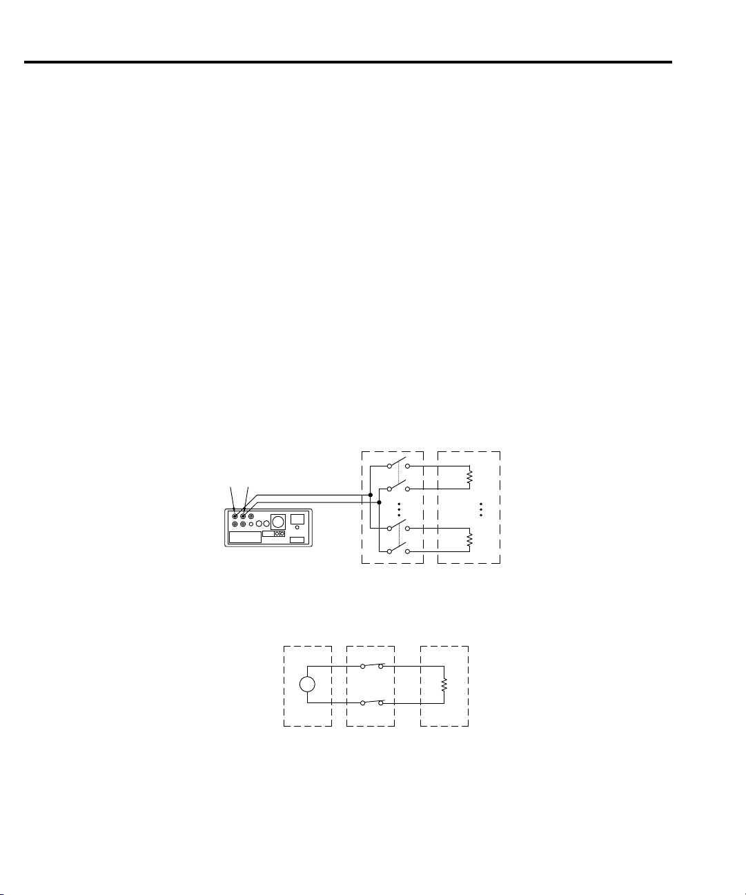
Figure 3-1 shows a typical test setup for making 2-wire resistance measurements. The
Model 2000-SCAN card provides the switching function, while the resistance measurements are
made by a Model 2000 Multimeter. Since only 2-pole switching is required for this application,
one Model 2000-SCAN card can be used to switch up to 10 resistors.
Measurement accuracy can be optimized by minimizing residual resistance: make connecting
wires as short as possible and limit the number of connectors to minimize path resistance.
Another technique is to short one of the scanner channel inputs, close the shorted channel, and
then enable the multimeter REL feature to null out path resistance. Leave REL enabled for the
entire test.
Page 49
1
DUTs
(5)
R
A. Test Configuration
B. Simplified Equivalent Circuit
5
6
10
1
5
HI
LO
Sense
HI
Sense
LO
HI
Sense HI
LO
Sense LO
2001
2000-SCAN
DUT
2000-SCAN
Ω
Out A
Out B
DMM Rear Panel
(Model 2001/2002 shown)
Figure 3-2
4-wire resistance
test connections
4-wire resistance tests
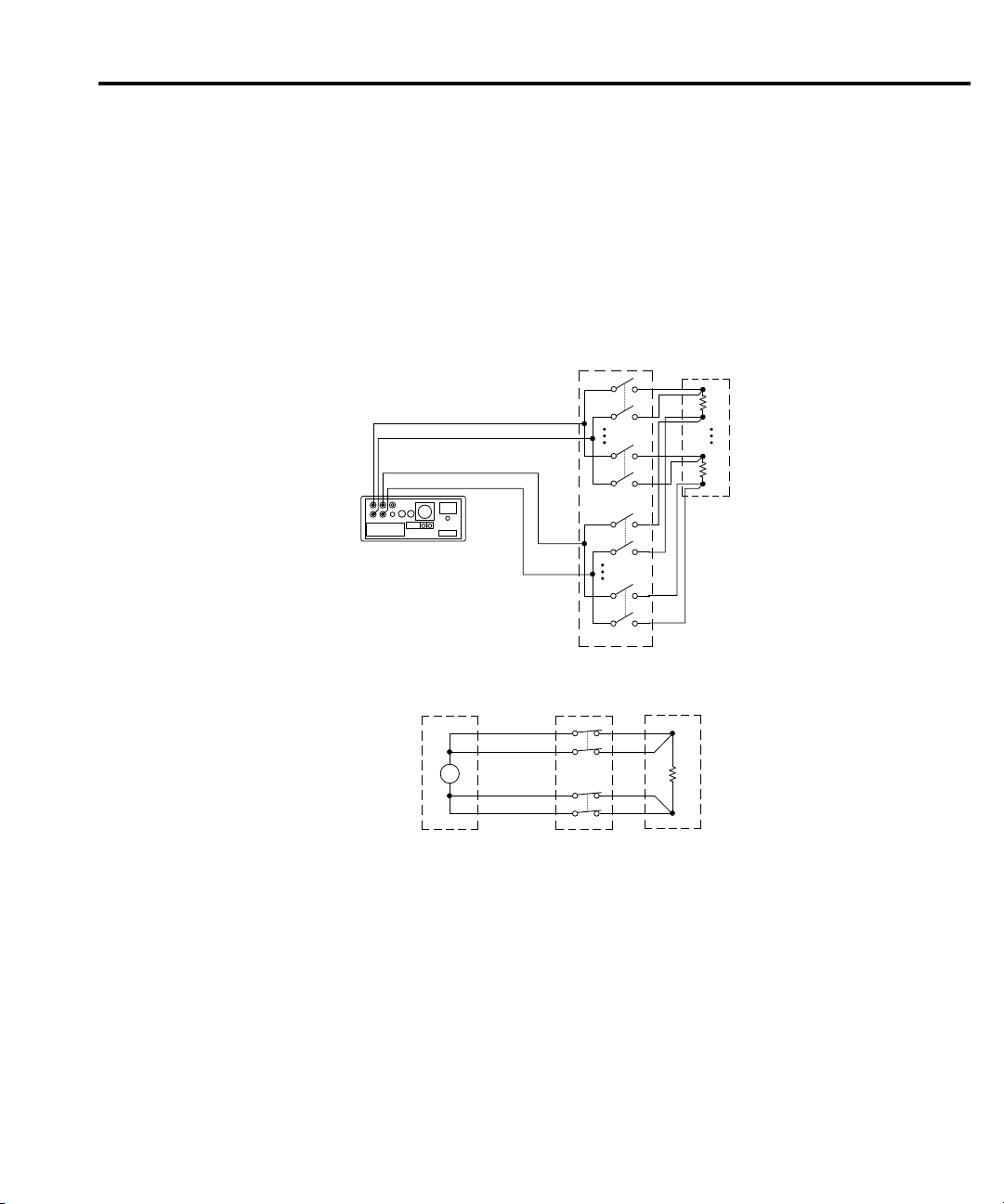
More precise measurements over a wider range of system and DUT conditions can be
obtained by using the 4-wire measurement scheme shown in Figure 3-2. Here, separate sense
leads from the Model 2000 Multimeter are routed through the scanner to the resistor under test.
The extra set of sense leads minimizes the effects of voltage drops across the test leads, greatly
reducing measurement errors with lower DUT resistances. Note, however, that an extra two
poles of switching are required for each resistor tested. For this reason, only five resistors can
be tested using this configuration.
Page 50
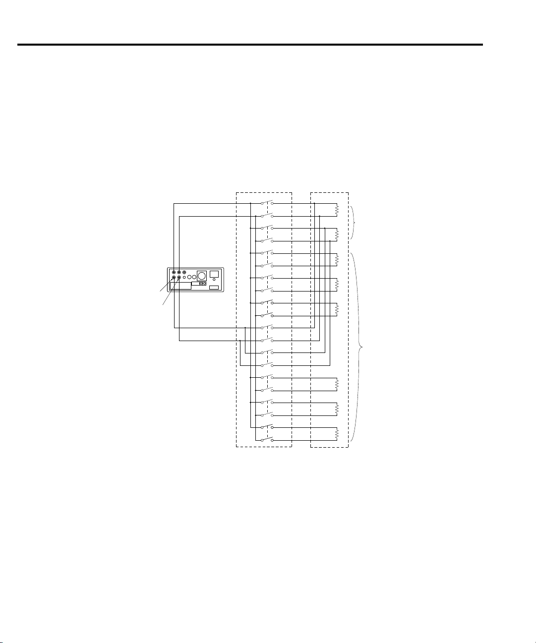
Combining 2-pole and 4-pole switching (Models 2001/2002)
CH 1
CH 2
CH 3
CH 4
CH 5
CH 6
CH 7
CH 8
CH 9
CH 10
DMM Rear Panel
(Model2001/2002
shown)
DUT's (8)
2000-SCAN
Out A
HI
LO
Input
HI
Input
LO
Sense
HI
Sense
LO
Out B
HI
LO
4-Pole
Connections
2-Pole
Connections
Figure 3-3
Combining 2-pole and
4-pole switching
(Model 2001/2002)
The Model 2000-SCAN can combine 2- and 4-pole switching in various combinations. For
example, you might require 4-pole switching for only two resistors, while the remaining
resistors could be tested using conventional 2-pole switching.
Figure 3-3 shows a test configuration using mixed 2-pole and 4-pole switching. Four-pole
switching is used only for device 1 (connected to channels 1 and 6) and device 2 (connected to
channels 2 and 7). Six more resistors are tested using 2-pole switching.
Measurement functions for each scanner channel are defined using the INTERNAL-CHANS
menu available by pressing CONFIG-CHAN (see “Using the scanner with the buffer” on
page 3–13). Measurement functions for this test would be set up as follows:
Channels 1 and 2: ¾4W
Channels 3, 4, 5 and 8, 10: ¾2W
Note that functions cannot be defined for channels 6 and 7 with this application because these
channels are paired with channels 1 and 2 for 4-pole switching.
Page 51
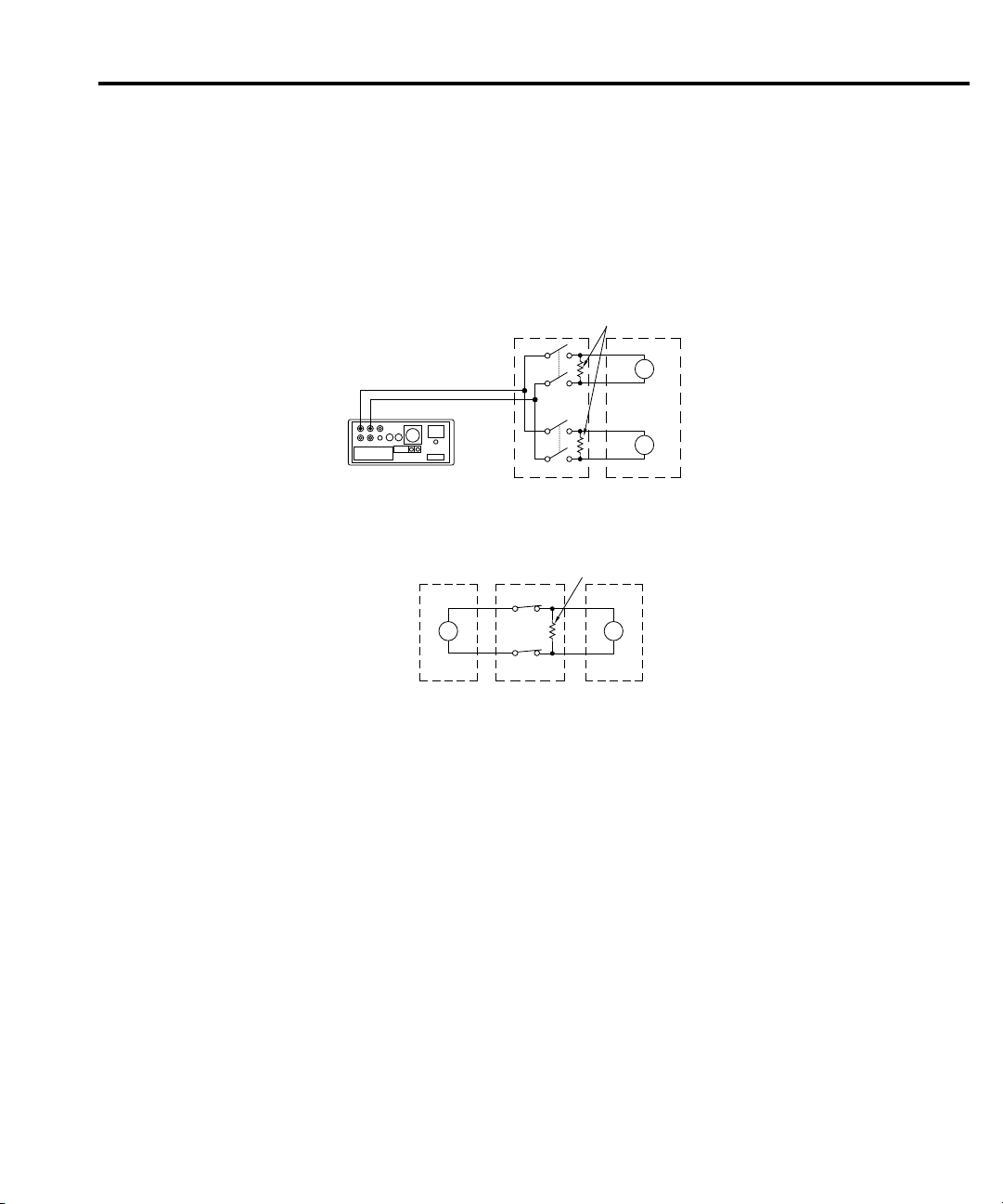
Current measurements
DUTs (2)
V
A. Test Configuration
B. Simplified Equivalent Circuit
DMM
2000-SCAN DUT
Out A
DMM Rear Panel
(Model 2001/2002)
A
A
A
HI
LO
User-installed
Shunts
User-installed
Shunt
CH 1
CH 6
2000-SCAN
Figure 3-4
Connections for current
measurements
Although the Model 2000-SCAN is not intended for direct current measurements, on-card
shunt resistors can be installed for channels 1 and 6 to allow for indirect current measurements.
Figure 3-4 shows the typical configuration for current measurements. Refer to Section 2 of this
manual for specific information on recommended shunt resistors and their installation.
calculation function. (Here, m = 1/R and b = 0.). The multimeter will then display the actual
current value. Refer to the multimeter Manuals for details on using math functions.
The current through each shunt resistor can be calculated as follows:
Where: I = current being determined
V = voltage measured by multimeter
R = shunt resistance value
Instead of manually calculating current, set up a Model 2000/2001/2002 mX + b math
Page 52
Measurement consider ations
R
E
DUT
DUT
R
PATH
V
R
IN
DUT
Scanner
Card
DMM
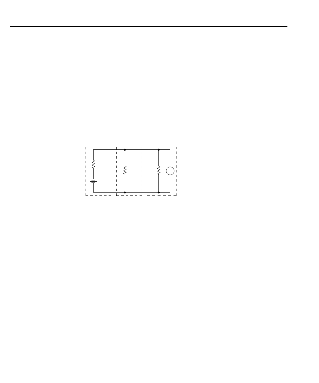
= Source Resistance of DUT
= Source EMF of DUT
= Path Isolation Resistance
= Input Resistance of Multimeter
R
DUT
E
DUT
R
PATH
R
IN
Figure 3-5
Path isolation
resistance
Many measurements made with the Model 2000-SCAN are subject to various effects that can
seriously affect low-le vel measurement accuracy . The following paragraphs discuss these effects
and ways to minimize them.
Path isolation
The path isolation is simply the equivalent impedance between any two test paths in a
measurement system. Ideally, the path isolation should be infinite, b ut the actual resistance and
distributed capacitance of cables and connectors results in less than infinite path isolation values
for these devices.
Path isolation resistance forms a signal path that is in parallel with the equivalent resistance
of the DUT , as shown in Figure 3-5. For lo w-to-medium device resistance values, path isolation
resistance is seldom a consideration; however, it can seriously degrade measurement accuracy
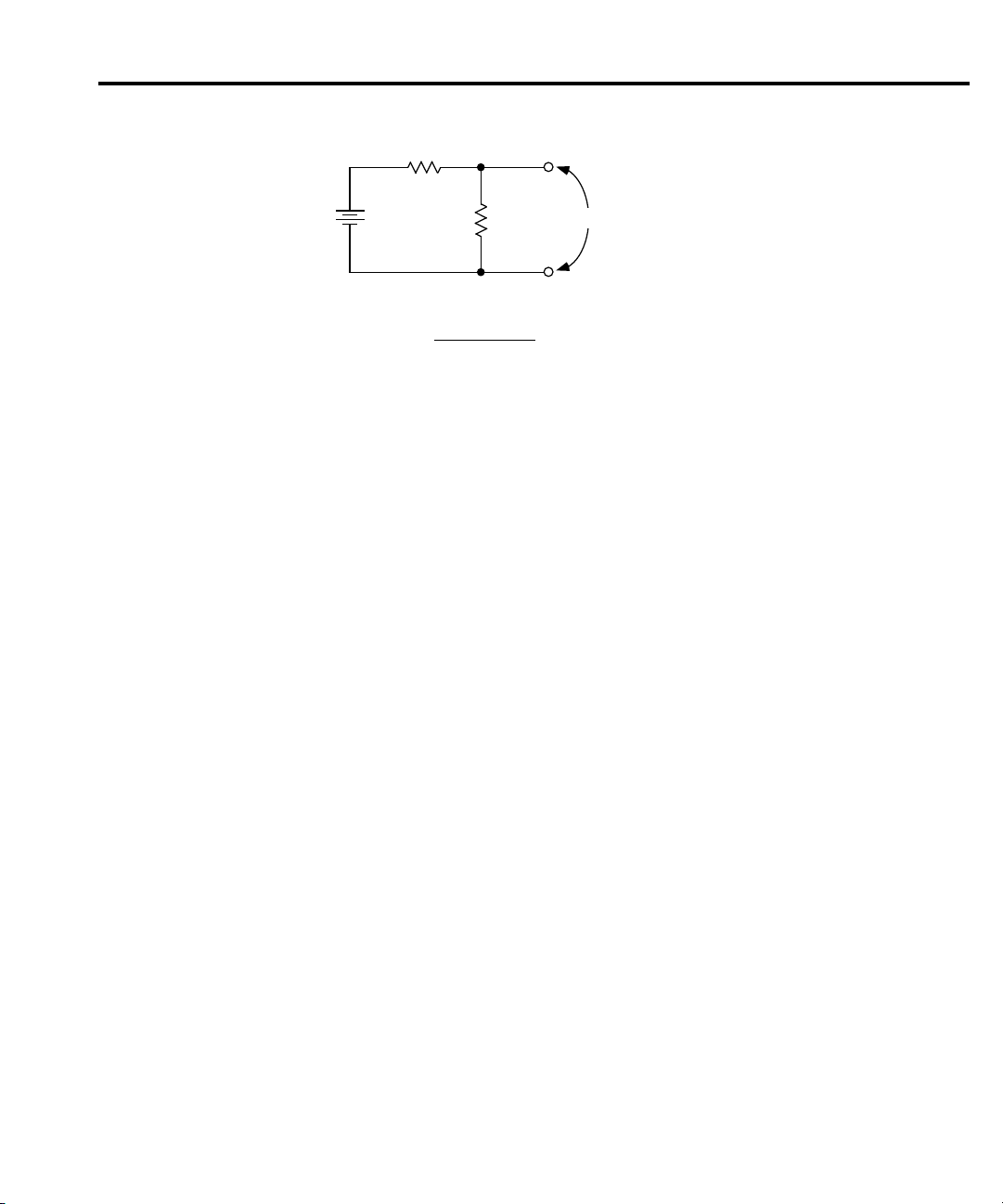
when testing high-impedance devices. The voltage measured across such a device, for example,
can be substantially attenuated by the voltage divider action of the device source resistance and
path isolation resistance, as shown in Figure 3-6. Also, leakage currents can be generated
through these resistances by voltage sources in the system.
Page 53
R
E
DUT
DUT
RPATH
E OUT
RPATH
R DUT RPATH
+
=
E
DUT
E OUT
Figure 3-6
Voltage attenuation by
path isolation
resistance
Magnetic fields
When a conductor cuts through magnetic lines of force, a very small current is generated.
This phenomenon will frequently cause unwanted signals to occur in the test leads of a scanning
system. If the conductor has sufficient length, even weak magnetic f ields like those of the earth
can create sufficient signals to affect lo w-le vel measurements. Two ways to reduce these effects
are: (1) reduce the lengths of the test leads, and (2) minimize the exposed circuit area. In extreme
cases, magnetic shielding may be required. Special metal with high permeability at low flux
densities (such as mu metal) is effective at reducing these effects.
Even when the conductor is stationary , magnetically-induced signals may still be a problem.
Fields can be produced by various signals such as the AC power line voltage. Large inductors
such as power transformers can generate substantial magnetic fields, so care must be taken to
keep the switching and measuring circuits a good distance away from these potential noise
sources. At high current levels, even a single conductor can generate significant fields. These
effects can be minimized by using twisted pairs, which will cancel out most of the resulting
fields.
Electromagnetic interference (EMI)
The electromagnetic interference characteristics of the Model 2000 Multimeter comply with
the electromagnetic compatibility (EMC) requirements of the European Union (EU) directives
as denoted by the CE mark. Howe ver, it is still possible for sensitive measurements to be af fected
by external sources. In these instances, special precautions may be required in the test setup.
Sources of EMI include:
• Radio and television broadcast transmitters.
• Communications transmitters, including cellular phones and hand-held radios.
• Devices incorporating microprocessors and high-speed digital circuits.
• Impulse sources as in the case of arcing in high-voltage environments.
The instrument, measurement leads, and other cables should be kept as far away as possible
from any EMI sources. Shielding measurement leads and the multimeter may reduce EMI to
acceptable levels. In extreme cases, a specially constructed screen room may be required to
sufficiently attenuate troublesome signals.
Page 54
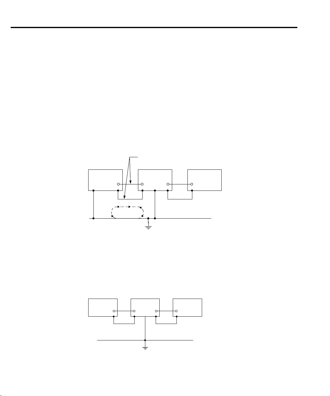
Many instruments incorporate internal filtering that may help reduce EMI effects. In some
Instrument 1 Instrument 2 Instrument 3
Power Line Ground
Signal Leads
Ground Loop
Current
Figure 3-7
Power line ground
loops
Instrument 1 Instrument 2 Instrument 3
Power Line Ground
Figure 3-8
Eliminating ground
loops
cases, additional external filtering may be required. Keep in mind, however, that filtering may
have detrimental effects on the measurement.
Ground loops
When two or more instruments are connected together, care must be taken to avoid unwanted
signals caused by ground loops. Ground loops usually occur when sensitive instrumentation is
connected to other instrumentation with more than one signal return path such as power line
ground. As shown in Figure 3-7, the resulting ground loop causes current to flow through the
instrument LO signal leads and then back through power line ground. This circulating current
develops a small but undesirable voltage between the LO terminals of the two instruments. This
voltage will be added to the source voltage, affecting the accuracy of the measurement.
Figure 3-8 shows how to connect sev eral instruments together to eliminate this type of ground
loop problem. Here, only one instrument is connected to power line ground. Ground loops are
not normally a problem with instruments having isolated LO terminals. However, all
instruments in the test setup may not be de-signed in this manner. When in doubt, consult the
manual for all instrumentation in the test setup.
Page 55

Keeping connectors clean
As is the case with any high-resistance device, the integrity of connectors can be
compromised if they are not handled properly. If connector insulation becomes contaminated,
the insulation resistance will be substantially reduced, affecting high-impedance measurement
paths. Oils and salts from the skin can contaminate connector insulators, reducing their
resistance. Also, contaminants present in the air can be deposited on the insulator surface. To
avoid these problems, never touch the connector insulating material. In addition, the scanner
card should be used only in clean, dry environments to avoid contamination.
If the connector insulators should become contaminated, either by inadvertent touching, or
from air-borne deposits, they can be cleaned with a cotton swab dipped in clean methanol. After
thoroughly cleaning, they should be allowed to dry for several hours in a low-humidity
environment before use, or they can be dried more quickly using dry nitrogen.
Page 56

Page 57

Service
Information
Service
Information
4
Page 58

Service Information
WARNING The information in this section is intended only for qualified service
Introduction
This section contains information necessary to service the Model 2000-SCAN scanner card
and is arranged as follows:
clean the card should it become contaminated.
Performance verification — Covers the procedures necessary to determine if the scanner
card meets stated specifications.
Special handling of static-sensitive devices — Reviews precautions necessary when
handling static-sensitive devices.
Principles of operation — Briefly discusses circuit operation.
Troubleshooting — Presents some troubleshooting tips for the Model 2000-SCAN including
relay replacement precautions.
personnel. Some of the procedures may expose you to hazardous voltages
that could result in personal injury or death. Do not attempt to perform these
procedures unless you are qualified to do so.
Discusses handling precautions and methods to
Handling and cleaning precautions
Because of the high-impedance areas on the Model 2000-SCAN, care should be taken when
handling or servicing the card to prevent possible contamination. The following precautions
should be observed when servicing the card.
Handling precautions
• Handle the card only by the edges and shields.
• Do not touch any board surfaces or components not associated with the repair.
• Do not touch areas adjacent to electrical contacts.
• When servicing the card, wear clean cotton gloves.
• Do not store or operate the card in an environment where dust could settle on the circuit
board.
• Use dry nitrogen gas to clean dust off the board if necessary.
Page 59

Soldering precautions
Should it become necessary to use solder on the circuit board, observe the following
precautions:
• Use an OA-based (organic activated) flux, and take care not to spread the flux to other
areas of the circuit board.
• Remove the flux from the work areas when the repair has been completed. Use pure
water along with clean cotton swabs or a clean, soft brush to re-move the flux.
• Once the flux has been removed, swab only the repaired area with methanol, then blo w
dry the board with dry nitrogen gas.
• After cleaning, the card should be allowed to dry in a 50°C low-humidity environment
for several hours before use.
P erformance verification
The following paragraphs discuss performance verification procedures for the
Model 2000-SCAN, including path resistance, contact potential, and isolation.
NOTE
Service Information 4-3
“Handling and cleaning precautions” on page 4-2 for information
on cleaning the card.
All verification measurements should be made at an ambient temperature between 18° and
28°C, and at a relative humidity of less than 70%.
Page 60
4-4 Service Information
Table 4-1 summarizes the equipment necessary for performance verification, along with an
application for each item.*
Table 4-1
Recommended verification equipment
Description Model/part Specifications Application
Multimeter
Electrometer with voltage
source
Sensitive Digital Voltmeter
Triax cable (unterminated)
Low-thermal cable
#22AWG solid copper wire
#22AWG Teflon-insulated
stranded wire
Jumper wires or connecting cables can simply be hard-wired directly to the screw terminals
of the Model 2000-SCAN. Detailed connection information is provided in Section 2.
Perform the following steps to verify that the path resistance of each channel is with specified
values.
1. Connect the HI and LO terminals of all 10 channel inputs together to make one common
NOTE Make sure that all jumper wir es are clean and free of oxides.
Keithley 2001
Keithley 617
20¾; 72ppm
10pA, 100pA; 1.6%
Control card, measure path resistance
Path isolation
100V source; 0.2%
Keithley 182
Keithley 7025
Keithley 1484
—
—
3mV; 60ppm
—
—
—
—
Contact potential
Path isolation
Contact potential
Path resistance
Path isolation
terminal using #22AWG solid copper jumper wires (see Figure 4-1).
2. Connect the output cables to OUT A HI and LO, as shown in Figure 4-1.
3. With the power of f, install the scanner card in the Model 2001 Multimeter .
4. Turn on the Model 2001, and allow it to warm up for one hour before proceeding.
5. Select the ¾2W function and the 20¾ range on the Model 2001.
6. Temporarily connect a second set of output leads, identical in length and type to the leads
connected to the scanner card output, to the Model 2001 rear panel HI and LO INPUT
jacks. Be sure to select the rear panel terminals with the front panel INPUT switch.
7. Short the free ends of the temporary leads together, and allow the reading to settle.
Enable the Model 2001 REL mode after settling, and leave REL enabled for the
remainder of the path resistance tests.
Page 61
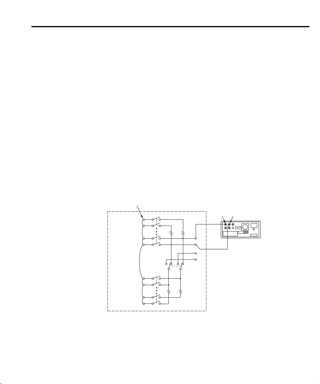
DMM Rear Panel
(Model 2001/2002
shown)
HI
LO
Channel 1
HI
LO
Channel 2-4
Channel 5
HI
LO
Channel 6
HI
LO
Channel 7-9
Channel 10
HI
LO
OUT A
OUT B
HI
LO
2-Pole
4-Pole
Jumper HI and LO
of all 10 Channels
Model 2000-SCAN
InputHIInput
LO
Figure 4-1
Connections for path
resistance checks
Service Information 4-5
8. Disconnect the temporary leads from the multimeter, and connect the output leads from
the scanner card to the rear panel HI and LO INPUT jacks (see Figure 4-1).
9. Close channel 1 as follows;
A. From normal display, press CHAN. The instrument will display the following:
B. Select CLOSE-CHANNEL, then press ENTER. The Model 2001 will display the
following:
C. Using the range and cursor ke ys, select channel 01, then press ENTER.
D. Press EXIT to return to normal display.
10. Note the resistance reading on the Model 2001. Verify that the reading is <2¾.
11. Repeat steps 9 and 10 for channels 2-9. Verify that the path resistance for each channel
is as follows:
channels 1-10: <2¾.
12. After completing the tests, turn off the Model 2001 power , remove the scanner card, and
remove all jumper wires (leave HI and LO shorted for each channel if you intend to
perform contact potential tests).
Page 62

4-6 Service Information
These tests check the EMF (contact potential) generated by each relay contact pair (HI and
LO) for each channel. The tests use a sensitive digital voltmeter (Model 182) to measure the
contact potential.
Perform the following procedure to check contact potential of each channel.
1. Connect 1” #22AWG copper jumper wires between the HI and LO terminals of each
channel input (see Figure 4-2).
2. Connect the Model 182 to OUT A HI and LO using the low-thermal cable (see
Figure 4-2).
3. With the power of f, install the scanner card in the Model 2001 Multimeter .
4. Turn on the Model 2001 and the Model 182 Sensitive Digital Voltmeter. Allow the
Model 182 to warm up for two hours before measurement.
5. Select the 3mV range on the Model 182.
6. Select the DCV function on the Model 2001.
7. Using the CHAN key , close channel 1 (see “Path resistance tests” on page 4-4 for
procedure).
8. Verify that the Model 182 reading is <1µV.
9. Repeat steps 7 and 8 for all 10 channels.
10. After completing all measurements, turn off the Model 2001 power, remo ve the scanner
card, and disconnect all jumpers and test leads.
Page 63
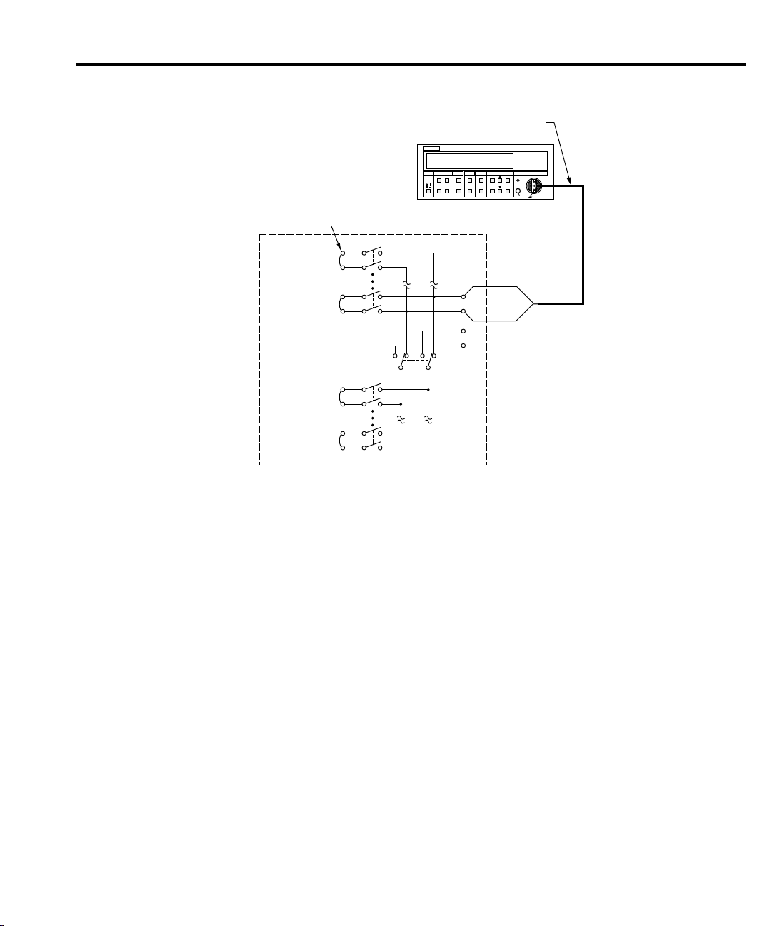
HI
LO
Channel 1
HI
LO
Channel 2-4
Channel 5
HI
LO
Channel 6
HI
LO
Channel 7-9
Channel 10
HI
LO
OUT A
OUT B
HI
LO
2-Pole
4-Pole
Connect bare copper jumpers between
HI and LO of each channel
Model 2000-SCAN
Model 1484
Low Thermal Cable
(Unterminated)
KEITHLEY
182 SENSITIVE DIGITAL VOLTMETER
Model 182
Figure 4-2
Connections for contact
potential tests
Service Information 4-7
Page 64
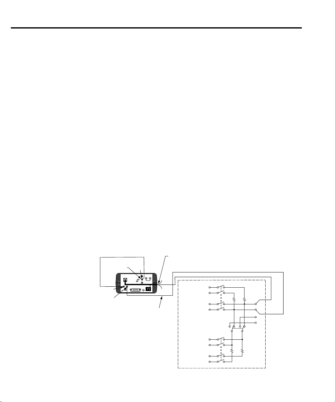
HI
LO
Channel 1
HI
LO
Channel 2-4
Channel 5
HI
LO
Channel 6
HI
LO
Channel 7-9
Channel 10
HI
LO
OUT A
OUT B
HI
LO
2-Pole
4-Pole
Model 2000-SCAN
HI
Model 617
INPUT
Model 7025
Unterminated
Triax Cable
(Red)
Banana to Banana Cable
Ground Link
Removed
Unterminated to
Banana Cable
Source V and
Measure V/I
Com
V-Source LO
V-Source HI
Figure 4-3
Connections for samechannel isolation tests
4-8 Service Information
These tests check the leakage resistance (isolation) between all HI and LO terminals and from
HI and LO terminals to chassis ground. In general, the test is performed by applying a voltage
(100V) across the terminals and then measuring the leakage current. The isolation resistance is
then calculated as R = V/I. In the following procedure, the Model 617 functions as a voltage
source and as an ammeter. In the V/I function, the Model 617 internally calculates the resistance
from the known voltage and current levels, and displays the resistance value.
Perform the following steps to check isolation:
1. Connect a 4” length of Teflon-insulated #22AWG stranded wire to every HI and LO
terminal on the scanner card (both inputs and outputs). Mark the free end of each wire
so you can identify wires when the scanner card is installed.
2. With the power of f, install the scanner card in the multimeter.
3. Turn on the Model 2001 power.
4. Turn on the Model 617, and allow the unit to w arm up for tw o hours for rated accurac y.
5. Select the Model 617 2pA range, and enable zero check and zero correct in that order.
Leave zero correct enabled for the entire procedure.
WARNING The following steps use high voltage (100V). Be sure to remove power from
the circuit before making connection changes.
6. Set the Model 617 voltage source for +100V, and select the 200nA current range. Make
sure the voltage source is still in standby.
7. Place the Model 617 in the V/I measurement function by pressing SHIFT OHMS.
8. With the Model 617 in standby , connect the electrometer to OUT A HI and LO terminals
of the scanner card, as shown in Figure 4-3.
Page 65
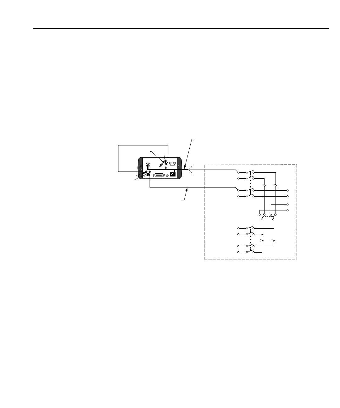
HI
LO
Channel 1
HI
LO
Channel 2-4
Channel 5
HI
LO
Channel 6
HI
LO
Channel 7-9
Channel 10
HI
LO
OUT A
OUT B
HI
LO
2-Pole
4-Pole
Model 2000-SCAN
HI
Model 617
INPUT
Model 7025
Unterminated
Triax Cable
(Red)
Banana to Banana Cable
Ground Link
Removed
Source V and
Measure V/I
Unterminated to
Banana Cable
Com
V-Source LO
V-Source HI
Figure 4-4
Connections for
channel-to-channel isolation tests
Service Information 4-9
9. Close channel 1 using the CHAN key (see “Path resistance tests” on page 4-4 for
details).
10. On the Model 617, disable zero check, and press OPERATE to source 100V.
11. After allowing the reading on the Model 617 to settle, verify that the reading is >1G¾
9
¾). This measurement represents the isolation resistance between the HI and LO
(10
terminals of channel 1.
12. Place the Model 617 in standby, and enable zero check.
13. Repeat steps 9 through 12 for channels 2 through 10. Be sure that the channel under test
is closed.
14. With the Model 617 voltage source in standby, connect the electrometer to the HI
terminals of scanner card channels 1 and 2, as shown in Figure 4-4.
15. Close channel 1 using the CHAN key.
16. On the Model 617, disable zero check, and press OPERATE to source 100V.
17. After allowing the reading on the Model 617 to settle, verify that the reading is >1G¾
18. Place the Model 617 in standby, and enable zero check.
19. Repeat steps 14 through 18 to measure isolation resistance between the channel 1 HI
20. Repeat steps 14 through 19 for the LO terminals of channels 1 through 10. Be sure the
9
¾). This measurement represents the isolation resistance between the HI terminals
(10
of channels 1 and 2.
terminal and channels 3 through 10 HI terminals. Be sure that the electrometer is
connected to the HI terminals of the two channels being tested, and that channel 1 is
closed.
electrometer is connected to the LO terminals of the two channels being tested, and that
channel 1 is closed.
Page 66
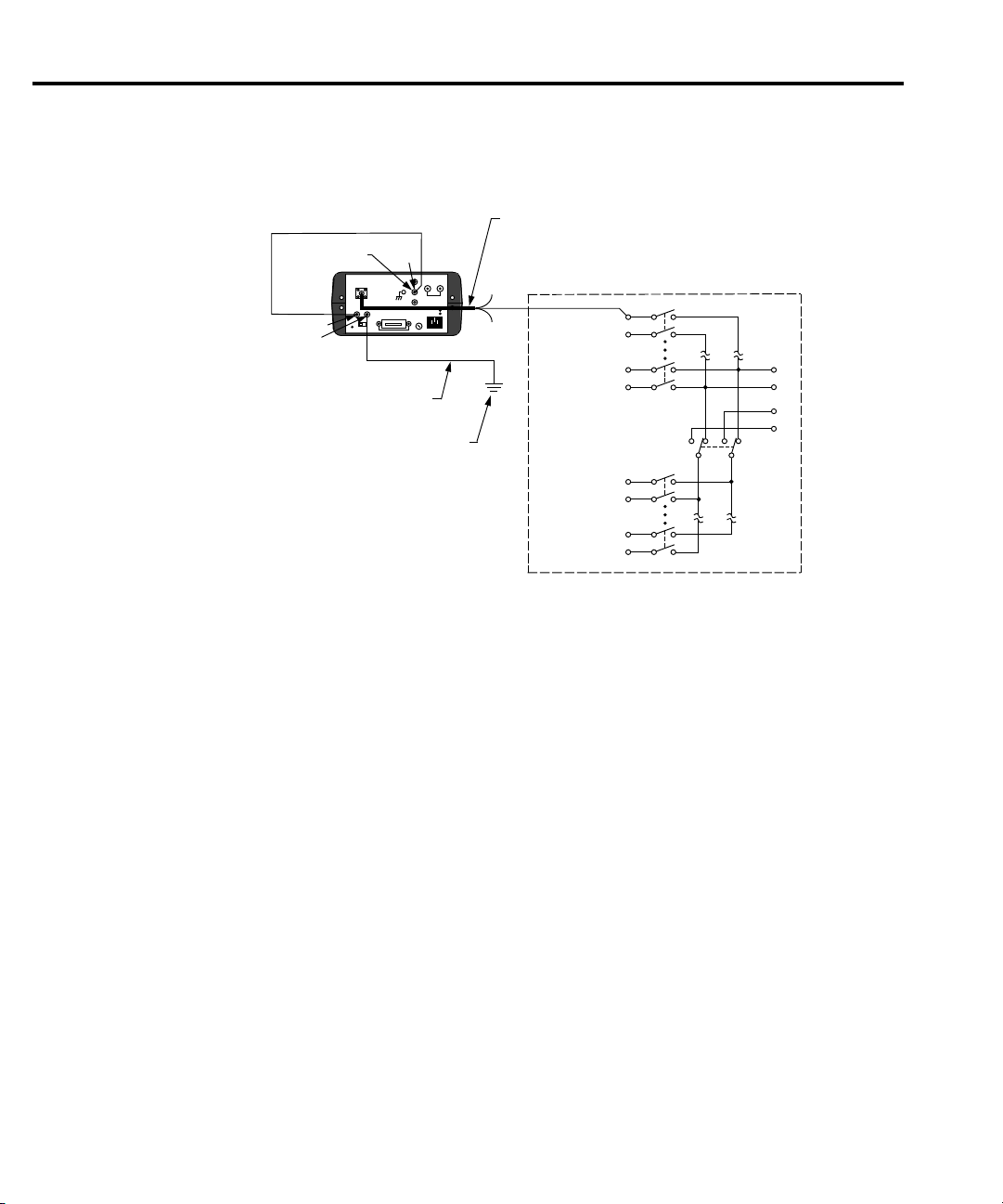
HI
LO
Channel 1
HI
LO
Channel 2-4
Channel 5
HI
LO
Channel 6
HI
LO
Channel 7-9
Channel 10
HI
LO
OUT A
OUT B
HI
LO
2-Pole
4-Pole
Model 2000-SCAN
HI
Model 617
INPUT
Model 7025
Unterminated
Triax Cable
(Red)
Banana to Banana Cable
Ground Link
Removed
Source V and
Measure V/I
Chassis Ground
Unterminated to
Banana Cable
Com
V-Source LO
V-Source HI
Figure 4-5
Connections for HI and
LO terminal to chassis
ground isolation tests
4-10 Service Information
21. With the electrometer voltage source in standby, connect the electrometer to channel 1
HI and chassis ground, as shown in Figure 4-5.
22. Program the Model 2000 to close channel 1.
23. On the Model 617, disable zero check, and press OPERATE to source +100V.
24. After allowing the reading on the Model 617 to settle, verify that it is >1G¾ (10
9
¾).
25. Put the electrometer in standby, and enable zero check.
26. Repeat steps 21 through 25 for channels 2 through 10. One electrometer lead should be
connected to the HI terminal of the channel being testing, and the other lead should be
connected to chassis ground.
27. Repeat steps 21 through 26 for channels 1 through 10 LO terminals. One electrometer
lead should be connected to the LO terminal of the channel being tested, and the other
lead should be connected to chassis ground. In addition, channel 1 should be closed.
Page 67
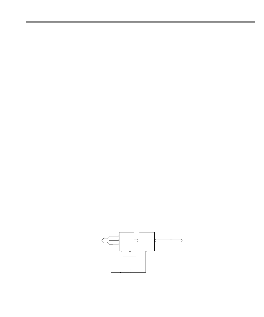
Special handling of static-sensitive de vices
To
Multimeter
Clock
Strobe
Enable
+5V
User Connections
Power-on
Reset
U104
Relays
K101-K111
Relay
Drivers
U101-U103
Data
Figure 4-6
Block diagram
CMOS and other high-impedance devices are subject to possible static discharge damage
because of the high-impedance levels involved. When handling such devices, use the
precautions listed below.
NOTE In order to prevent damage, assume that all parts are static-sensitive.
1. Such devices should be transported and handled only in containers specially designed to
prevent or dissipate static b uild-up. T ypically , these devices will be received in anti-static
containers made of plastic or foam. Keep these parts in their original containers until
ready for installation or use.
2. Remove the devices from their protective containers only at a properly grounded
workstation. Also, ground yourself with an appropriate wrist strap while working with
these devices.
3. Handle the devices only by the body; do not touch the pins or terminals.
4. Any printed circuit board into which the device is to be inserted must first be grounded
to the bench or table.
5. Use only anti-static type de-soldering tools and grounded-tip soldering irons.
Principles of operation
The following paragraphs discuss the basic operating principles for the Model 2000-SCAN,
and can be used as an aid in troubleshooting the card. The schematic drawing of the card is
shown on drawing number 2000-176, located at the end of Section 5 of this manual.
Block diagram
Figure 4-6 shows a simplified block diagram of the Model 2000-SCAN. Key elements
include the relay drivers and relays, as well as the po wer-up reset circuit. These various elements
are discussed in the following paragraphs.
Page 68

Relay control
Card relays are controlled by serial data transmitted via the relay DAT A line. A total of three
bytes are shifted in serial fashion into latches located in the card relay driver ICs. The serial data
is clocked in by the CLOCK line. As data overflows one re gister , it is fed out the Q’S line of the
register down the chain.
Once all three bytes have shifted into the card, the STROBE line is set high to latch the relay
information into the Q outputs of the relay drivers, and the appropriate relays are energized
(assuming the driver outputs are enabled, as discussed below). Note that a relay driver output
goes low to energize the corresponding relay .
Switching circuits
Relays K101 through K106 and K108 to K111 perform input switching, while K107
configures the card for 2-pole or 4-pole operation.
Po wer -on safeguar d
A power-on safeguard circuit, made up of U104 and associated components, ensures that
relays do not change state on power-up and power -down. This circuit disables all relay actuation
during power-up and power-down periods by holding the OE (output enable lines) high during
these periods.
Page 69
T r oubleshooting
T roubleshooting equipment
T able 4-2 summarizes recommended equipment for troubleshooting the Model 2000-SCAN.
Table 4-2
Recommended troubleshooting equipment
Description Manufacturer and model Application
Multimeter
Oscilloscope
Keithley 2000/2001
TEK 2243
T roubleshooting access
In order to gain access to the scanner card circuit board to measure voltages under actual
operating conditions, perform the following steps:
1. Turn off the Model 2000 power, and disconnect the line cord and all other equipment.
2. If wires are connected to the scanner card, remove the scanner card from the multimeter .
3. Remove the Model 2000 cover as follows:
A. Remove the handle by rotating it to align the arrows on the handle mounting ears.
Pull out and remove the handle.
B. Remove the screws that secure the handle mounting ears, then remove the ears.
C. Remove the screws that attach the rear bezel to the case, then remove the bezel.
D. Remove the bottom screws that grounds the case to the chassis.
W ARNING Be sure to install and tighten the grounding screws after replacing the cover.
E. Remove the cover by pulling it off towards the rear.
4. Disconnect any wires connected to the scanner card terminal blocks.
5. Install the scanner card in the multimeter.
6. Connect the line cord, and turn on the power to measure voltages (see following
paragraph).
DCV checks
View logic waveforms
Page 70
T roubleshooting pr ocedure
Table 4-3 summarizes scanner card troubleshooting steps. Refer to the schematic diagram
and component layout drawings at the end of Section 5 for component locations.
WARNING Lethal voltages are present within the Model 2000. Some of the procedures
may expose you to hazardous voltages. Observe standard safety precautions
for dealing with live circuits. Failure to do so could result in personal injury
or death.
CAUTION Use care when removing relays from the PC board to avoid pulling traces
away from the circuit board. Before attempting to remove a relay, use an
appropriate de-soldering tool, such as a solder sucker, to clear each mounting
hole completely free of solder. Each relay pin must be free to move in its
mounting hole before removal. Also, make certain that no burrs are present
on the ends of the relay pins.
NOTE To avoid contamination, which could degrade card performance, always handle the
card only by the side edges and covers. Do not touch edge connectors, boar d surfaces,
or components on the card. Also, do not touch areas adjacent to electrical contacts
on connectors.
Table 4-3
Troubleshooting procedure
Step Item/component Required condition Comments
1
Digital ground P1034,
pin 1, 3, 5
2
P1034, pin 9
3
U101, pin 2
4
U101, pin 3
5
U101, pin 7
6
U101-U103, pins 10-18
+5VDC
CLOCK pulses
DATA pulses
STROBE pulse
Low when rel ay state
is changed.
All voltages referenced to digital
ground.
Card power supply voltage.
Serial clock pulse s.
Serial data pulses.
End of relay update sequence.
High when relay is not changing
state. Relay driver outputs.
Page 71

Replaceable
Parts
Replaceable
Parts
5
Page 72

Replaceable Parts
Introduction
This section contains replacement parts information, schematic diagram, and component
layout drawing for the Model 2000-SCAN.
P arts list
A parts list for the scanner card is included in a table integrated with schematic diagram and
component layout drawing for the board. Parts are listed alphabetically in order of circuit
designation.
Ordering information
To place an order, or to obtain information concerning replacement parts, contact your
Keithley representative or the factory (see inside front cover for addresses). When ordering
parts, be sure to include the following information:
• Card model number (2000-SCAN)
• Card serial number
• Part description
• Circuit description, if applicable
• Keithley part number
F actory ser vice
If the card is to be returned to Keithley Instruments for repair, perform the following:
• Call the Instruments Division Repair Department at 1-800-552-1115 for a Return
Material Authorization (RMA) number.
• Complete the service form at the back of this manual and include it with the card.
• Carefully pack the card in the original packing carton.
• Write ATTENTION REPAIR DEPT and the RMA number on the shipping label.
NOTE
Page 73

Replaceable Parts 5-3
Component lay out and schematic diagr am
A component layout drawing and schematic diagram are included on the following pages
integrated with the parts list for the Model 2000-SCAN.
Keithley part
no.
C101-103, 105, 106
C107
J1035,1036
K101-111
P1034
R134
R147
U101-103
U104
Card Ejector
Clip, Strain Relief
Shield, Scanner Bottom
Shield, Scanner Top
Sleeved Banana Plug Test Lead
Strain Relief, Bottom
Strain Relief, Top
Strip, Polyurethane
CAP, .1UF,20%,50V, CERAMIC
CAP, 100UF, 20%, 25V, ALUM ELEC
CONN, FEMALE, 12 PIN
RELAY, MINATURE (DPDT) TQ2E-L2-5V
CONN, FEMALE DUAL 16-PIN
RES, 1K, 5%, 1/4W, COMPOSITION OR FILM
RES, 4.7K, 5%, 1/4W, COMPOSITION OR FILM
IC, 8-BIT SERIAL-IN LATCH DRIVER, 5841A
IC, SUPPLY VOLTAGE SUPERVISOR, TL7705AC
FA-237
2001-351
2001-341
2001-342
CA-109
2001-344
2001-349
2001-345-1
C-365-.1
C-413-100
CS-768-12
RL-155
CS-455
R-76-1K
R-76-4.7K
IC-536
IC-602
Page 74

5-4 Replaceable Parts
Page 75

Index
C
Card Connections and Installation 2-1
Card installation and removal 2-15
Output connections to multimeter 2-17
Scanner Card Installation 2-16
Scanner card removal 2-18
Component layout and schematic diagram 5-3
Connections 2-3
Card configuration 2-4
Card connectors 2-5
Connection precautions 2-3
Dressing leads 2-8
Output connections 2-7
Wiring procedure 2-6
F
Factory service 5-2
Features 1-2
G
General Information 1-1
H
Handling and cleaning precautions 4-2
Handling precautions 4-2
Soldering precautions 4-3
Handling precautions 2-2
M
Manual addenda 1-3
Measurement considerations 3-20
Electromagnetic interference (EMI) 3-21
Ground loops 3-22
Keeping connectors clean 3-23
Magnetic fields 3-21
Path isolation 3-20
Model 2000 Multimeter front panel scanner
controls and SCPI scanner commands 3-4
Closing channels 3-4
Configuring scan parameters 3-5
Opening channels 3-4
Selecting measurement function 3-5
Model 2001/2002 front panel scanner controls
and SCPI scanner commands 3-8
Closing channels 3-8
Opening channels 3-9
Scanning channels 3-10
Using the scanner with the buffer 3-13
O
Operation 3-1
Ordering information 5-2
P
Parts list 5-2
Performance verification 4-3
Contact potential tests 4-6
Environmental conditions 4-3
Isolation tests 4-8
Path resistance tests 4-4
Recommended equipment 4-4
Scanner card connections 4-4
Principles of operation 4-11
Block diagram 4-11
Power-on safeguard 4-12
Relay control 4-12
Switching circuits 4-12
R
Repacking for shipment 1-4
Replaceable Parts 5-1
RTD temperature measurements 3-14
S
Safety symbols and terms 1-3
Scanner card detection 3-3
Power-up detection 3-3
Scanner option bus query 3-3
SCPI scanner commands 3-7
Service Information 4-1
Signal limitations 3-3
Relay input 3-3
Special handling of static-sensitive
devices 4-11
Specifications 1-3
T
Troubleshooting 4-13
access 4-13
equipment 4-13
procedure 4-14
Typical applications 3-16
Current measurements 3-19
Resistor testing 3-16
2-wire resistance tests 3-16
4-wire resistance tests 3-17
Combining 2-pole and 4-pole
switching (Models
2001/2002) 3-18
Typical connecting schemes 2-9
Page 76

Current measurements 2-12
Board cleaning 2-13
Current connections 2-14
Current measurements 2-13
Current shunt locations 2-12
Recommended current shunt
values 2-12
Resistance connections 2-10
2-Pole connections 2-10
4-Pole connections 2-11
Voltage connections 2-9
U
Unpacking and inspection 1-4
Handling precautions 1-4
Inspection for damage 1-4
Instruction manual 1-4
Shipment contents 1-4
 Loading...