

Page 1

DOC0535
10 July 2019, 16:56
www.keit.co.uk
User Manual
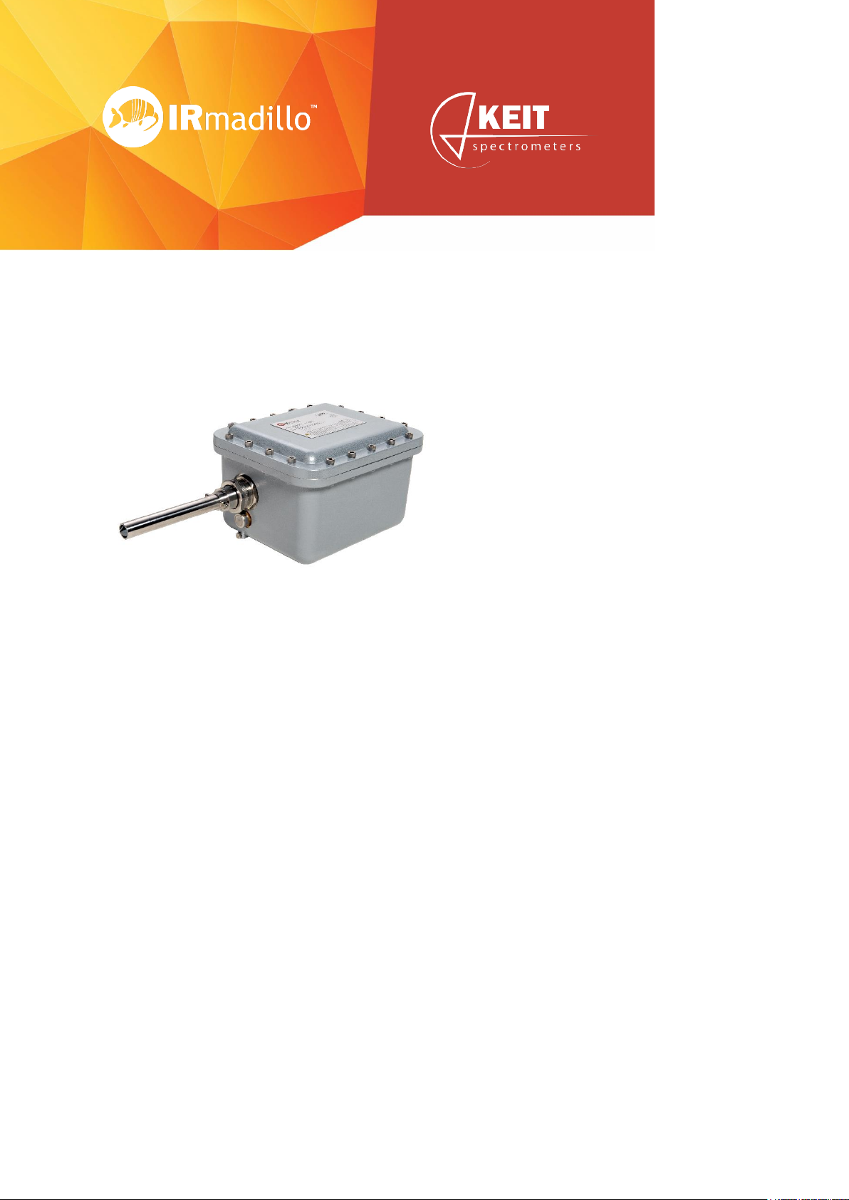
Rugged FTIR Spectrometer for Real-Time Process Analysis
Page 2

User Manual Page 2
www.keit.co.uk DOC0535 10 July 2019, 16:56
Table of Contents
Table of Contents ..................................................................................................... 2
Contact Keit .............................................................................................................. 6
1. Introduction ........................................................................................................ 7
1.1 Introduction to the IRmadillo ................................................................................... 7
1.2 Brief introduction to infrared spectroscopy .............................................................. 7
1.3 How FTIR spectrometers work ................................................................................ 8
1.4 What makes the IRmadillo different? ...................................................................... 8
2. System overview ................................................................................................ 9
2.1 System configuration ............................................................................................ 10
2.2 Controller .............................................................................................................. 10
2.3 Software ............................................................................................................... 10
3. Safety ................................................................................................................ 11
3.1 General safety ...................................................................................................... 11
3.2 Lifting instructions ................................................................................................. 11
3.3 Electrical safety ..................................................................................................... 12
3.4 Hazardous environment safety – Ex-certified models ............................................ 12
3.5 Pressure safety notes ........................................................................................... 14
3.6 Ventilation and location ......................................................................................... 14
4. Installation ........................................................................................................ 15
4.1 Installation location ............................................................................................... 15
4.2 Spectrometer components .................................................................................... 16
4.2.1 Product label (A) ............................................................................................ 16
4.2.2 Probe purge outlet (B) .................................................................................... 17
4.2.3 Probe (C) ....................................................................................................... 17
4.2.4 ATR Element (D) ........................................................................................... 17
4.2.5 Breather (E) ................................................................................................... 17
4.2.6 Earthing point (F) ........................................................................................... 17
4.2.7 Probe purge inlet (G) ..................................................................................... 17
4.2.8 Spectrometer body purge inlet (H) ................................................................. 17
4.2.9 Communication port (I) .................................................................................. 17
4.2.10 Power cable port (J) ....................................................................................... 18
Page 3

User Manual Page 3
www.keit.co.uk DOC0535 10 July 2019, 16:56
4.2.11 Mounting holes (K) ......................................................................................... 18
4.3 Connection to a vessel or pipeline for measuring .................................................. 19
4.3.1 Fluid tight seal to the instrument .................................................................... 19
4.4 Electrical installation ............................................................................................. 20
4.4.1 Uninterruptible power supply (UPS) ............................................................... 20
4.4.2 Ensuring a power connection to the spectrometer ......................................... 20
Table 1 – IRmadillo power specifications ..................................................................... 20
4.4.3 Connecting the power cable to the instrument ............................................... 21
4.5 Data communication connection ........................................................................... 23
4.5.1 Connecting the data communication cable to the spectrometer ..................... 23
4.5.2 Connecting the USB communication cable to the controller ........................... 23
4.5.3 Connecting the fibre data communication cable to the controller.................... 24
4.6 Purging the unit ..................................................................................................... 25
4.7 Stabilisation period................................................................................................ 26
5. Using the system and software ...................................................................... 27
5.1 Software version: 4.0.7 ......................................................................................... 27
5.2 Getting started ...................................................................................................... 27
5.2.1 Manual sample acquisition ............................................................................. 27
5.2.2 Continuous collection ..................................................................................... 27
5.2.3 Collect a background scan ............................................................................. 27
5.2.4 Manual sample acquisition ............................................................................. 29
5.2.5 Monitoring a reaction or process .................................................................... 30
5.3 The Spectrometer tab ........................................................................................... 31
5.4 Manual sample acquisition .................................................................................... 36
5.5 Configure acquisition ............................................................................................ 41
5.6 Batch viewer ................................................................................................ ......... 44
5.7 Reaction monitor ................................................................................................... 49
5.8 Configure chemometrics ....................................................................................... 51
5.8.1 Supported model types .................................................................................. 53
5.8.2 Editing Camo model settings ......................................................................... 54
5.8.3 Common chemometrics errors ....................................................................... 55
5.9 Log viewer ............................................................................................................ 56
5.10 Offline viewer ................................ ................................................................ ........ 59
6. Data communication integration and configuration ..................................... 60
Page 4

User Manual Page 4
www.keit.co.uk DOC0535 10 July 2019, 16:56
6.1 Modbus communications ...................................................................................... 60
6.1.1 Configure Keit controller ................................................................................ 60
6.1.2 Holding registers ............................................................................................ 62
6.1.3 Representation of data in Modbus ................................................................. 62
6.1.4 Modbus RTU tutorial ................................................................ ...................... 63
6.2 Modbus TCP server .............................................................................................. 66
6.2.1 Getting started with Modbus TCP .................................................................. 67
6.3 OPC-UA ................................................................................................................ 68
6.3.1 Licensing the OPC-UA server ........................................................................ 69
6.3.2 UaExpert client .............................................................................................. 70
6.3.3 OPC address space ....................................................................................... 70
6.4 Controller administrator guidance ......................................................................... 73
6.5 Connecting the spectrometer to Camo Analytics’ Process Pulse .......................... 74
7. Maintenance ..................................................................................................... 76
7.1 Service and support contacts ................................................................................ 76
7.2 Preventative maintenance and service intervals ................................................... 76
7.3 Protecting and cleaning the dip probe ATR element ............................................. 76
7.3.1 Cleaning instructions: infrared glass probes ................................................... 77
7.3.2 Cleaning instructions: diamond probes .......................................................... 78
7.4 Cleaning prior to Sterilise-in-Place (SIP) ............................................................... 79
7.5 ATR and O-ring ..................................................................................................... 79
7.6 Cleaning the fibre optic data cable connectors ...................................................... 79
7.7 Troubleshooting .................................................................................................... 82
7.8 Remote Health Check ........................................................................................... 83
7.8.1 Remote access .............................................................................................. 83
7.8.2 Sending data manually .................................................................................. 84
8. Accessories...................................................................................................... 85
8.1 Sample cell ........................................................................................................... 85
8.2 Flow cell ................................................................................................................ 86
8.2.1 Introduction .................................................................................................... 86
8.2.2 Safety ............................................................................................................ 86
8.2.3 Specifications and safety limits (flow cell) ...................................................... 87
8.2.4 Installation ..................................................................................................... 88
8.2.5 Maintenance .................................................................................................. 91
Page 5

User Manual Page 5
www.keit.co.uk DOC0535 10 July 2019, 16:56
8.2.6 Cleaning ........................................................................................................ 92
8.3 Flanged probe (Ex certified) .................................................................................. 93
8.3.1 Introduction .................................................................................................... 93
8.3.2 Safety ............................................................................................................ 93
8.3.3 Specifications and safety limits (welded flange probe) ................................... 94
8.3.4 Installation ..................................................................................................... 94
8.3.5 Maintenance .................................................................................................. 96
Appendix 1: Technical Specification Sheet (Model ASM0627, Ex-Certified
IRmadillo) ................................................................................................................ 97
Appendix 2: Controller Specifications ................................................................ 98
Appendix 3: Technical Drawings IRmadillo ...................................................... 101
Appendix 4: Declarations of Conformity ............................................................ 104
Declaration of Conformity - IRmadillo (Ex-Certified Spectrometer) ................................ 104
Declaration of Conformity - Controller ............................................................................ 105
Declaration of Conformity – Flow Cell ............................................................................ 106
FCC Class A emissions statement ................................................................................ 107
Page 6

User Manual Page 6
www.keit.co.uk DOC0535 10 July 2019, 16:56
Contact Keit
Website: www.keit.co.uk
Postal address: Keit Ltd.
Unit 4, Zephyr Building
Eighth Street, Harwell Campus
Didcot
Oxfordshire
OX11 0RL
United Kingdom
The triangle symbol on the product label means essential safety information
must be followed to prevent user injury or damage to the instrument. Before
installing or using the product the user must refer to and comply with the safety
notices in Section 3.
Page 7
Page 7
www.keit.co.uk Introduction: DOC0535 10 July 2019, 16:56
Back to Table of Contents
1. Introduction
1.1 Introduction to the IRmadillo
The IRmadillo is a vibration-tolerant, mid-infrared process spectrometer designed to enable
monitoring of either batch or continuous processes of liquids in a range of industries.
The IRmadillo has no moving parts and a rigid probe which is inserted directly into the reaction
vessel or process pipeline for continuous real-time analysis. The device is tolerant of extreme
vibration levels. The spectrometer can be combined with either multivariate analysis (i.e.,
chemometrics), or univariate analysis (i.e., peak height tracking) to act as a concentration
meter. This allows for accurate monitoring of a process/reaction state in real time at the point
of production.
1.2 Brief introduction to infrared spectroscopy
Spectroscopy is the study of how molecules interact with light. There are many different types
of spectroscopy spanning a wide range of light wavelengths (i.e., infrared, UV-visible,
microwave, NMR using radiowaves, and X-ray spectroscopy).
Infrared (IR) spectroscopy is a powerful technique that monitors chemicals by looking at the
vibration of chemical bonds. Different molecular bonds – and therefore chemical components
– can be identified at various parts of the infrared spectral range from near-infrared (NIR), to
mid-infrared (MIR) and far-infrared. Of these, the mid-infrared region is the most informationrich area of the spectrum and therefore highly desirable for use in analysis.
Page 8

User Manual Page 8
www.keit.co.uk Introduction: DOC0535 10 July 2019, 16:56
Back to Table of Contents
1.3 How FTIR spectrometers work
Fourier transform infrared spectrometers (FTIRs) use a computational process (Fourier
transform) that interprets the information of an interference pattern (interferogram) in the midinfrared region to generate a spectrum.
Conventional FTIR instruments use a Michelson interferometer which consists of a pair of
moving mirrors, designed to split and recombine light into an interference pattern. However,
the moving mirrors make the instrument highly sensitive to vibration, and therefore not suitable
for direct use in industrial environments.
To work around this, some manufacturers have coupled conventional FTIR spectrometers with
long fibre optic probes connected to the instrument which has been removed to a stable safe
zone at some distance. Unfortunately, current fibre optic probe design is known to have a
fragile nature and is prone to performance failure when bent, handled, or twisted; again making
it difficult to achieve real-time process monitoring in a manufacturing environment.
1.4 What makes the IRmadillo different?
The IRmadillo is an FTIR instrument in that it creates an interferogram and requires a Fourier
transform to interpret the information for a spectrum. But rather than using a moving mirror to
create the interferogram it uses a proprietary arrangement of fixed mirrors to create an
interference pattern.
Unlike conventional FTIR spectrometers, the IRmadillo has no moving parts, making it
extremely resistant to vibration and therefore able to be used directly in the manufacturing
environment. It can be fixed directly onto the side of a reaction vessel or pipe at the point of
production rather than remotely located. This enables manufacturers to continuously monitor
their chemical reactions in real time with an in-line analytical instrument. The IRmadillo is an
innovation in process analytical technology that changes how manufacturers can monitor and
control their processes.
Page 9
Page 9
www.keit.co.uk System overview: DOC0535 10 July 2019, 16:56
Back to Table of Contents
2. System overview
Page 10

User manual Page 10
www.keit.co.uk System overview: DOC0535 (10 July 2019, 16:56)
Back to Table of Contents
2.1 System configuration
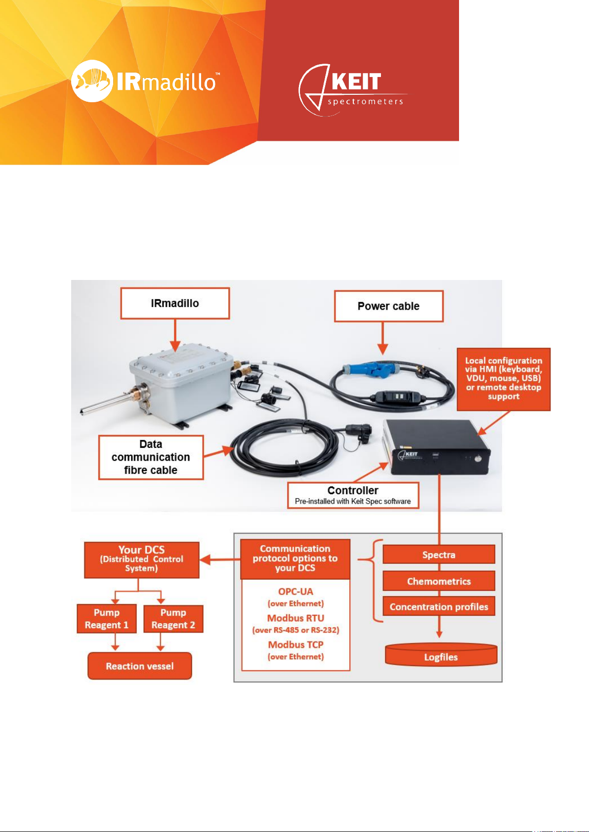
The following communication protocols with the distributed control system (DCS) are currently
supported:
• OPC-UA over Ethernet
• Modbus RTU over RS-485 or RS-232
• Modbus TCP over Ethernet
• Others: contact Keit Ltd.
Historical records of spectra and detailed instrument diagnostics are stored locally on the
controller for preventative maintenance and fault finding.
The logfile is a record of registered events, configuration changes and errors.
The Data Link to the DCS allows only minor configuration changes. Significant changes can
only be made by logging into the controller locally using a keyboard, visual display unit (VDU),
and mouse.
2.2 Controller
The controller is delivered with the spectrometer software (Keit Spec) pre-installed. The
standard industrial controller allows direct connection of the system cables.
The controller is an industrial-grade computer which performs signal processing and provides
spectra and chemometrics data to the DCS.
2.3 Software
See Section 5 Using the system and software for full details. The controller uses the Microsoft
Windows 10 IOT operating system. It comes pre-configured with the following software:
Keit Spectrometer
(Keit Spec)
This auto-runs on startup and is the default application. It allows
viewing and saving of real-time data.
Project Viewer
For viewing of previously recorded spectra and diagnostics
information.
Log file viewer
For viewing the log of user interaction with the system
If you have any questions on the installation, please contact [email protected].
Page 11
Page 11
www.keit.co.uk Safety: DOC0535 (10 July 2019, 16:56)
Back to Table of Contents
3. Safety
The term “WARNING” is used to inform you about situations that could result in personal
injury to yourself or other persons. The term “CAUTION” is used to inform you about situations
that could result in damage to the spectrometer or other equipment.
Failure to follow the requirements shown in this section may lead to the safety of the
equipment being compromised.
3.1 General safety
WARNING
The spectrometer weighs ~18 kg; take care when handling it
to avoid injury.
CAUTION
Do not operate outside the specified range of environmental
or analyte conditions specified on the product label.
CAUTION
The probe is NOT a carry handle; it will be damaged if used to
support the instrument.
CAUTION
Do not open the spectrometer.
3.2 Lifting instructions
The instrument can be carefully lifted by the lip around the top face or with hands underneath
its base. Do not use the probe as a carry handle. It will be damaged if used to support the
instrument. It is the responsibility of the user to suitably risk assess the handling of the
instrument and provide suitable equipment if necessary.
Page 12
User Manual Page 12
www.keit.co.uk Safety: DOC0535 (10 July 2019, 16:56)
Back to Table of Contents
3.3 Electrical safety
WARNING
The Keit-supplied electrical mains cable must be earthed and
should include a 5A fuse as well as a means of isolating both
live and neutral; obey local electrical safety codes.
WARNING
An additional earth connection must be provided to the
enclosure chassis exterior via the provided M6 screw.
WARNING
Never disconnect the mains power connector when
energised.
CAUTION
Residual current protection or ground fault interrupter
devices are advised.
3.4 Hazardous environment safety – Ex-certified models
WARNING
The spectrometer is sealed at the factory; do not open the
spectrometer.
WARNING
Do not operate outside the range of environmental or analyte
conditions specified on the product label; consult Keit to
check compatibility with your analyte or process conditions.
WARNING
Dust particles must be excluded from the monitored media.
WARNING
The device contains safety-critical breathers; do not restrict
air flow around it.
WARNING
The spectrometer’s Ex protection relies on the gas purge
ports being either plugged or connected to a clean air line. Do
not leave the ports open.
CAUTION
Protect the spectrometer probe tip from impact and under no
circumstances use the probe as a carry handle.
The Ex-certified version of this product (ASM0627-XX) was assessed against the following
standards against the following standards for hazardous environments:
• IEC60079-0 Explosive Atmospheres – Equipment General Requirements
• IEC60079-1 Explosive Atmospheres – Equipment protection by flameproof enclosures
• IEC60079-26 Explosive Atmospheres – Equipment with EPL Ga
In addition, IEC60079-28 Explosive Atmospheres – Protection of equipment using optical
radiation was considered but the equipment is not in the scope of this standard because (ref
section 1, part 5) it has an enclosure that fully contains the optical radiation and provides IP6X
protection in accordance with IEC60529 Degrees of protection provided by enclosures (IP
code).
Page 13
User Manual Page 13
www.keit.co.uk Safety: DOC0535 (10 July 2019, 16:56)
Back to Table of Contents
Furthermore, elements of IEC60079-31 Explosive Atmospheres – Equipment dust ignition
protection by enclosure have been applied to preclude optical absorbers from entering the
probe.
In accordance with IEC60079-26, the rigid dip probe achieves EPL Ga and can be inserted
into zone 0 environments while the main instrument achieves EPL Gb for use in zone 1. The
user should be aware that creating an opening in a zone 0 environment may lead to the release
of flammable gas and flame entrance. EPL Ga is achieved for the dip probe since it is an
enclosure providing protection against dust ignition. The dip probe tube is made of Hastelloy
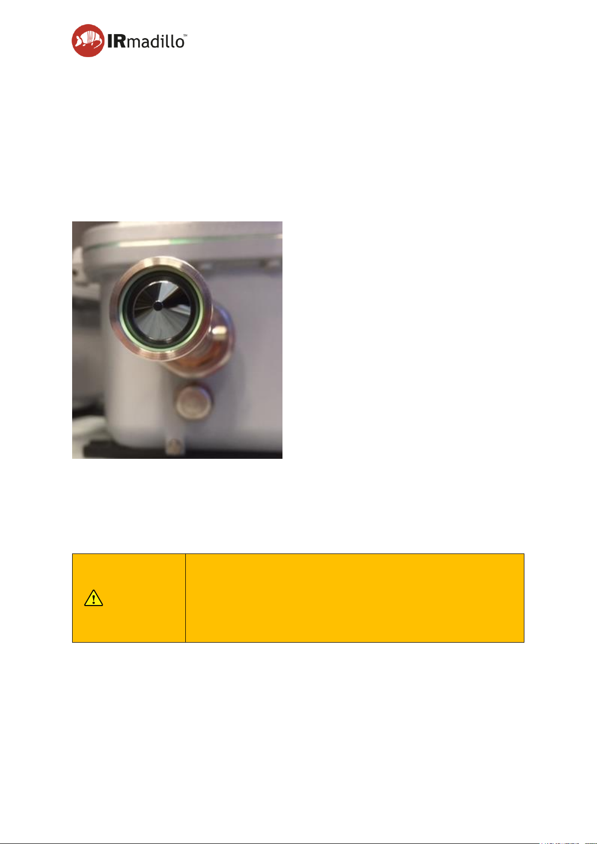
C-276 or stainless steel 316L. The tip is made of an amorphous infrared (chalcogenide) glass
and provides the interface to liquid analytes. The glass is sealed within the dip probe tube by
means of a perfluoroelastomeric (FFKM) O-ring. Stainless steel, Hastelloy and FFKM are inert
materials and not known to suffer corrosion in most environments.
CAUTION
Infrared glass should not be used in chemicals with pH >9. If in
doubt, consult Keit Ltd.
The following Specific Conditions of Use (also known as X conditions) apply:
• The media to be monitored must be an area where dust particles are excluded
• The dip probe must be mounted so that it is protected from impact
• Contact Keit for advice regarding material compatibility before installing the spectrometer
in a process
Page 14
User Manual Page 14
www.keit.co.uk Safety: DOC0535 (10 July 2019, 16:56)
Back to Table of Contents
3.5 Pressure safety notes
Do not exceed the pressure or temperature limits stated on the product label as this could be
dangerous and will invalidate the warranty. The suitability of the instrument for various
pressures, temperatures and their rates of change is process dependent (even if the limits are
within those marked on the product label). Contact Keit for advice before installing the
spectrometer in a process.
The ATR element and its O-ring form a pressure boundary. The ATR element is made from
an infrared glass which is fragile. For safe operation it should show no signs of damage; refer
to Section 6 Maintenance for further details.
3.6 Ventilation and location
The spectrometer is thermally stabilised and designed to operate in a variety of conditions and
environments.
WARNING
Purging the instrument with dry nitrogen or air is strongly
recommended for optimum performance (Note: Maximum inlet
gauge pressure of 1 Barg, with a flow rate between 0.5 Litre/min
and 2 Litre/min). When using nitrogen, it is imperative to ensure
adequate ventilation to prevent asphyxiation. The use of an
oxygen sensor is recommended.
Page 15

Page 15
www.keit.co.uk Installation: DOC0535 (10 July 2019, 16:56)
Back to Table of Contents
4. Installation
4.1 Installation location
The spectrometer is suitable for indoor or outdoor use.
Parameters
Value
Units
Pollution degree of intended
environment
4
Maximum installation altitude
3000
metres
Pollution degree of the environment refers to the level of contamination that the exterior of the
device can cope with. Pollution degree 4 means that continuous conductivity from conductive
dust, rain or other wet conditions will not cause electrical safety to be compromised. The Ex
certifications for this product do not cover protection from flammable or explosive dusts.
Page 16
User Manual Page 16
www.keit.co.uk Installation: DOC0535 (10 July 2019, 16:56)
Back to Table of Contents
4.2 Spectrometer components
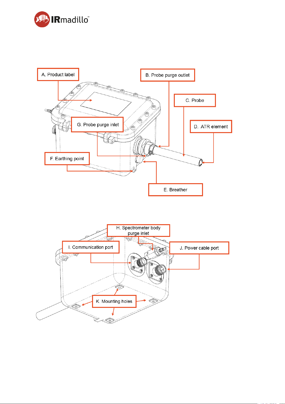
See Appendix 3: Technical Drawings IRmadillo for detailed drawings
4.2.1 Product label (A)
The product label specifies the model of instrument with permissible environmental and
analyte operating conditions, along with applicable certification.
Page 17
User Manual Page 17
www.keit.co.uk Installation: DOC0535 (10 July 2019, 16:56)
Back to Table of Contents
4.2.2 Probe purge outlet (B)
Allows purge gas to escape the probe.
4.2.3 Probe (C)
The probe is designed to be installed directly into a reaction vessel or pipe and is made of a
non-corroding metal.
4.2.4 ATR Element (D)
The ATR element at the end of the probe is made of an infrared glass that will be damaged
by chemicals with pH >9. Contact [email protected] for advice before installing the
spectrometer in a process.
The material of the ATR element is fragile. It is important to keep the element clean because
this is where the spectrometer interacts with analytes. See page 76 Protecting and cleaning
the dip probe ATR element for more information.
CAUTION
Do not expose the ATR element to alkaline (basic) solutions
with pH > 9 as this will cause irreversible damage to the ATR
and will invalidate the warranty. Contact Keit for advice
regarding material compatibility.
4.2.5 Breather (E)
Do not obstruct the breather.
4.2.6 Earthing point (F)
The spectrometer body has an M6 earth attachment point below the probe. This should be
used in addition to earthing through the power supply cable.
WARNING
Failure to properly earth the spectrometer may cause serious
injury or death.
4.2.7 Probe purge inlet (G)
The spectrometer has been fitted with two 4mm outside diameter (OD) purge inlet ports. One
of these purges the probe. More detail on how to purge the instrument is given on page 25
Section 4.6 Purging the unit.
4.2.8 Spectrometer body purge inlet (H)
The spectrometer has been fitted with two 4mm outside diameter (OD) purge inlet ports. One
of these purges the body. More detail on how to purge the instrument is given on page 25
Section 4.6 Purging the unit.
4.2.9 Communication port (I)
The connectors are specifically designed to work in hazardous zones and have IP65 rating.
More detail on how to connect them to the cables is given on page 23 in section Data
Page 18

User Manual Page 18
www.keit.co.uk Installation: DOC0535 (10 July 2019, 16:56)
Back to Table of Contents
communication connection. The Spectrometer may be configured to accept a fibre-optic data
cable or a USB cable.
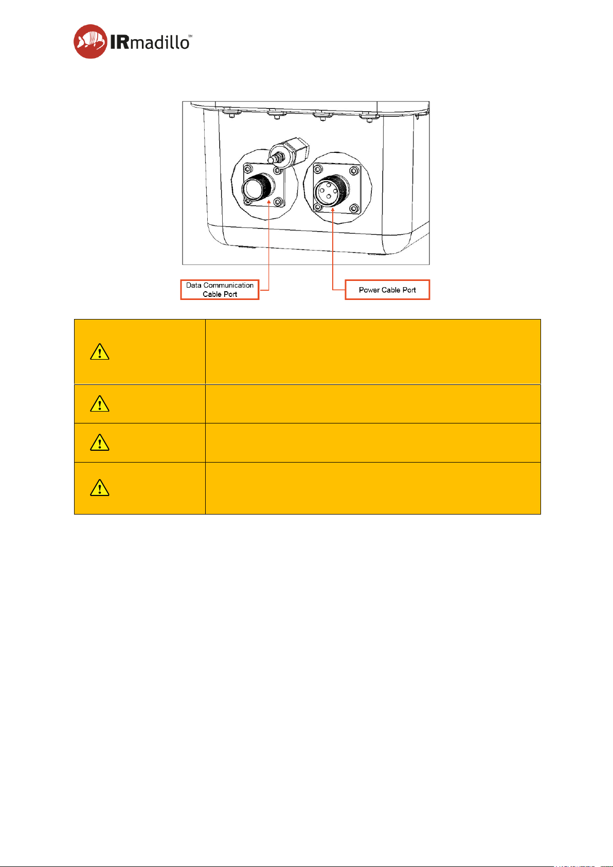
4.2.10 Power cable port (J)
The connectors are specifically designed to work in hazardous zones and have IP65 rating.
More detail on how to connect them to the cables is given on page 19 in section Electrical
installation.
4.2.11 Mounting holes (K)
The spectrometer should be supported using the four M8 mounting holes in its base. Note that
the spectrometer weighs~18 kg.
Page 19

User Manual Page 19
www.keit.co.uk Installation: DOC0535 (10 July 2019, 16:56)
Back to Table of Contents
4.3 Connection to a vessel or pipeline for measuring
4.3.1 Fluid tight seal to the instrument
Probe installation into the analyte or process fluid is unique for each application and is not
covered in this user guide. Safe installation of the probe into the process is the responsibility
the user and should be assessed by a suitably trained person.
Page 20
User Manual Page 20
www.keit.co.uk Installation: DOC0535 (10 July 2019, 16:56)
Back to Table of Contents
4.4 Electrical installation
NOTE
See Page 12 Section Electrical safety prior to attempting installation.
The spectrometer is normally supplied with a blunt-cut mains cable to be wired into your
electrical supply. The instrument requires single-phase mains input and must be connected to
a permanent earth (grounding) connection. A 5A fuse should be fitted in the live/hot supply
connection.
Provide a means of isolating both live and neutral by fitting a disconnecting switch or using a
suitable circuit breaker that meets the requirements of IEC 60947-1 and IEC 60947-3. The
switch must be located within easy reach of the instrument and must be marked as the
disconnection device for the equipment. The disconnecting device must not interrupt the earth
connection.
4.4.1 Uninterruptible power supply (UPS)
Ensure that a reliable power supply is available. An uninterruptible power supply (UPS) is
strongly recommended. Contact [email protected] for further information.
4.4.2 Ensuring a power connection to the spectrometer
Unless otherwise specified, the power cable will be delivered blunt cut.
The spectrometer is designed to operate over a wide range of voltages shown below in Table
1. If you plan to operate the spectrometer outside of these ranges, contact Keit for advice
before powering up the instrument.
Table 1 – IRmadillo power specifications
Parameters
Value
Units
AC input voltage
100-240
V
AC input frequency
50/60
Hz
Mains supply fluctuations (% of
Nominal Value)
±10
%
Power consumption
100 (max)
W
Overvoltage Category
CAT II
Page 21
User Manual Page 21
www.keit.co.uk Installation: DOC0535 (10 July 2019, 16:56)
Back to Table of Contents
4.4.3 Connecting the power cable to the instrument
WARNING
Always disconnect the power source first before connecting
or disconnecting the power cable to the spectrometer. Never
connect the power cable to the spectrometer when
energised.
NOTE
Ensure the mains and data communication ports and cable
connectors are dry prior to mating.
NOTE
Keep the dust caps on connectors and fibres when not in
use. Never leave an exposed fibre connector.
NOTE
Tighten the set (grub) screws on the power and data cables
when connected. This is a condition of use for these
connectors.
Page 22
User Manual Page 22
www.keit.co.uk Installation: DOC0535 (10 July 2019, 16:56)
Back to Table of Contents
Step 1. Ensure the power cable is not live. Unscrew the cover on the spectrometer’s power
connector (larger connector on the right-hand side) and on the mating power cable.
Ensure the connectors and ports are dry.
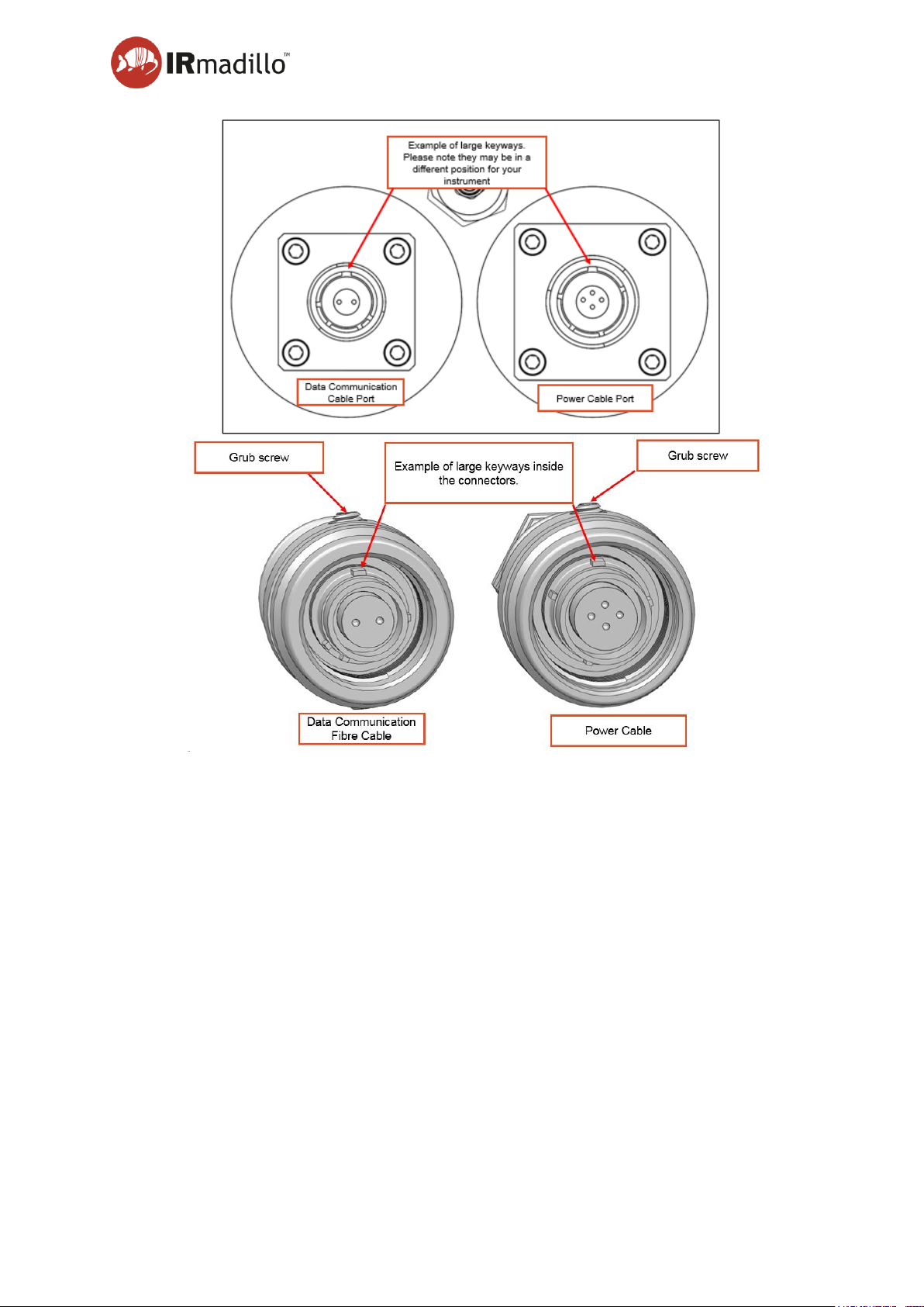
Step 2. The cable fits in one position only; there are 5 keyways that must line up. The largest
keyway can be used to line them up. The connector will click into place when aligned.
Step 3. Fully tighten the fastening ring by turning clockwise.
Step 4. To lock the connectors in place and comply with their Ex certificate, tighten the grub
screws indicated by the arrows in the image above.
Step 5. Fit the connector cover that is attached to the rear of the spectrometer with the cap
that is attached to the power cable.
Step 6. Connect the power cable to the mains power supply.
Step 7. The spectrometer is now powered up and will start thermally stabilising.
Page 23

User Manual Page 23
www.keit.co.uk Installation: DOC0535 (10 July 2019, 16:56)
Back to Table of Contents
4.5 Data communication connection
4.5.1 Connecting the data communication cable to the spectrometer
The data communication cable may be USB or fibre optic depending on the configuration of
the spectrometer.
Step 1. Unscrew the cover on the spectrometer’s data communication port (the left-hand side
connector) and the mating data communication fibre cable.
Step 2. The cable fits in one position only; there are 5 keyways that must line up. The largest
keyway can be used to line them up. The cable will click into place when aligned.
Step 3. Fully rotate the fastening ring clockwise until the connection is secure.
Step 4. To lock the connector in place and comply with its Ex certificate, tighten the grub
screws indicated by the arrows in the previous image.
Step 5. Fit the connector cover that is attached to the rear of the spectrometer with the cap
that is attached to the power cable.
4.5.2 Connecting the USB communication cable to the controller
Take the Male USB A plug at the end of the data cable and insert it into one of the USB ports
on the back of the controller.
Note: The Data Link display light on the front of the controller will not come on when the
spectrometer is connected to the controller via USB.
Page 24
User Manual Page 24
www.keit.co.uk Installation: DOC0535 (10 July 2019, 16:56)
Back to Table of Contents
4.5.3 Connecting the fibre data communication cable to the controller
Step 1. Remove the dust cap from the data communication cable.
Step 2. Carefully match up the data communication cable with the corresponding port on the
back of the controller.
Step 3. Tighten the locking nut. This will make a secure connection.
Step 4. To lock the connectors in place and comply with their Ex certificate, tighten the grub
screws indicated by the arrows in the image above.
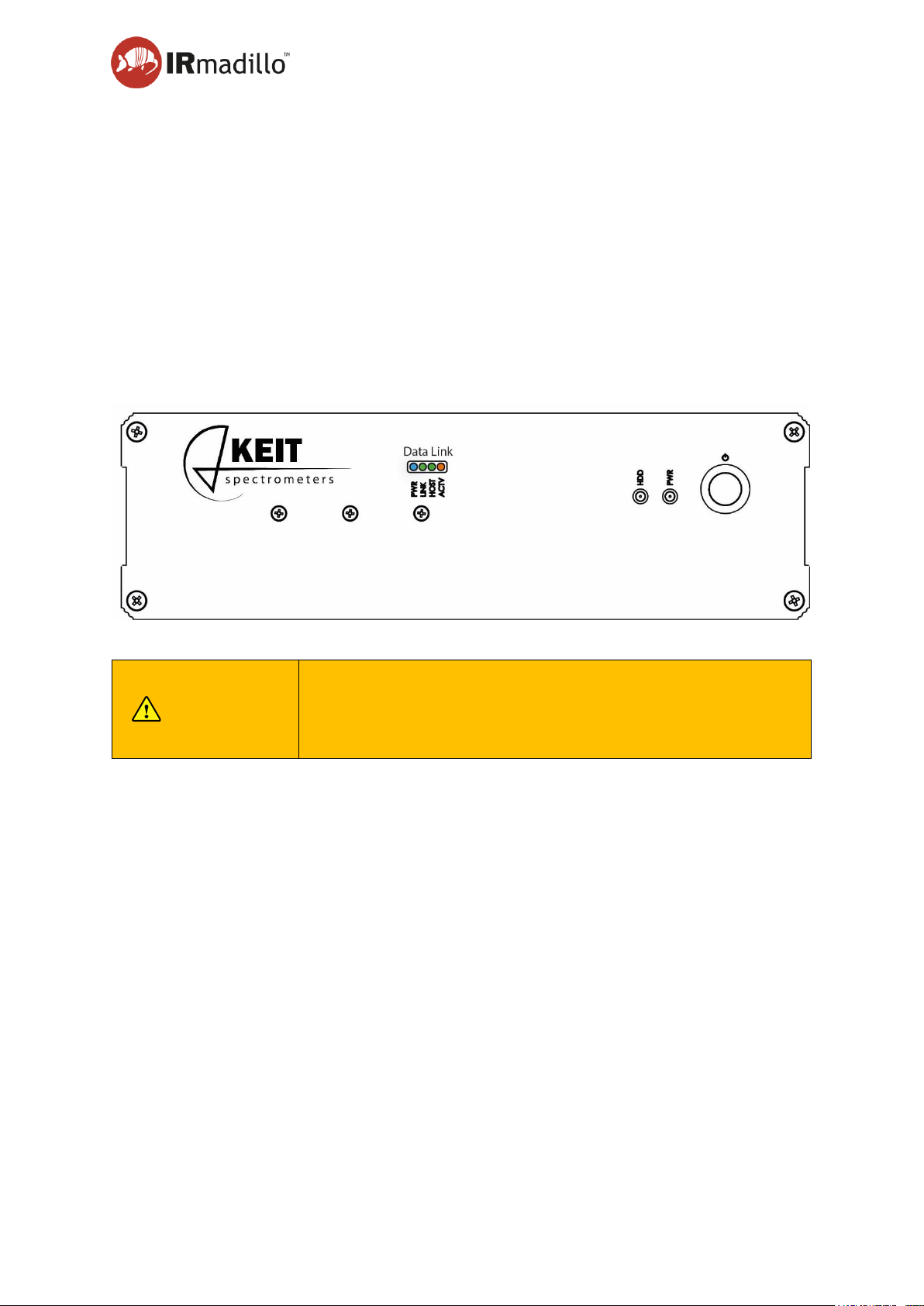
Step 5. Check that the green and orange lights on the controller are present (see image).
Step 6. If the lights are not visible consult the troubleshooting guide, page 82, Section 7.7
Troubleshooting.
NOTE
Protect the data communication fibre from stress and tight
bends (< 80mm bend radius not allowed!). Tight bends cause
a stress at the glass surface and increase the probability of
fracture.
Page 25
User Manual Page 25
www.keit.co.uk Installation: DOC0535 (10 July 2019, 16:56)
Back to Table of Contents
4.6 Purging the unit
The IRmadillo spectrometer is designed to be continuously purged. This eliminates any
interference in operation caused by water vapour and carbon dioxide within the instrument;
both interact strongly with infrared (IR) light.
Suitable purge gases:
• Dry, oil-free (compressed) air
• Dry nitrogen
CAUTION
Ensure purge gas is free of oil, grease and particulates.
Impurities may cause damage.
NOTE
All FTIR instruments are very sensitive to water vapour and
carbon dioxide. Even in well-controlled environments, e.g.,
laboratories, environmental changes can be large enough to
cause significant changes in the spectrum. It is STRONGLY
recommended to purge the instrument at all times.
To purge the instrument:
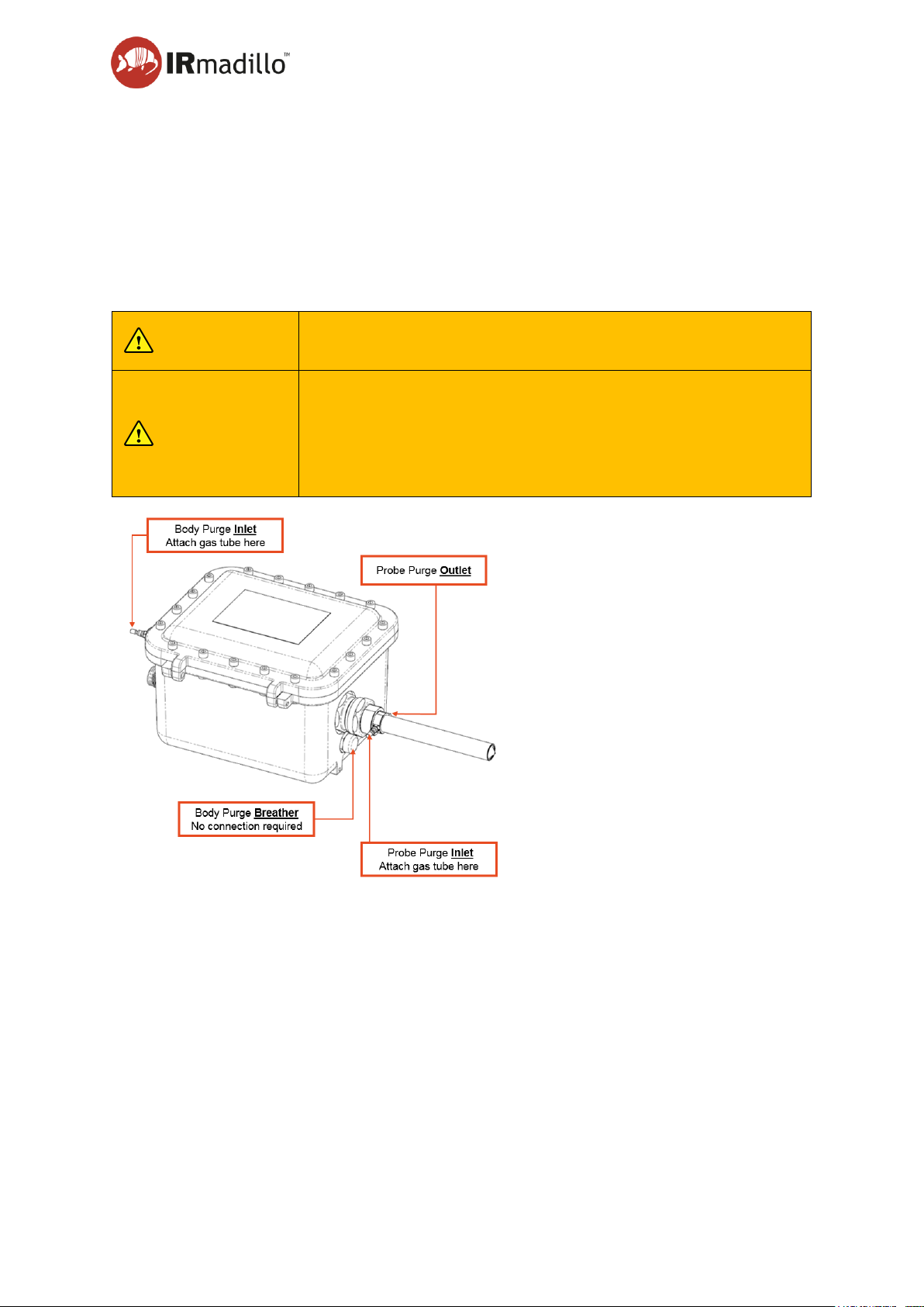
Step 1. Connect a 4mm diameter gas hose to the probe purge inlet port. NB Do not confuse
the inlet with the OUTLET which is on the opposite side of the probe.
Step 2. Connect a 4mm diameter gas hose to the body purge inlet port on the instrument.
Step 3. Ensure both gas tubes are connected to a suitable gas supply.
Step 4. Adjust the total flow to 0.5 to 2 L per minute, with a maximum gauge pressure of 1
Barg.
Step 5. Do not turn off the flow during normal operation.
Step 6. If the purge tubing is disconnected, a blanking plug must be fitted to the inlet
connection on the probe to maintain the IP rating and exclude dust.
Page 26

User Manual Page 26
www.keit.co.uk Installation: DOC0535 (10 July 2019, 16:56)
Back to Table of Contents
4.7 Stabilisation period
The IRmadillo requires a stabilisation period of >12 hours once powered on and purged. This
is to allow the internal components to reach a stable temperature and humidity. Once fully
dried out the instrument is very robust against changes in ambient conditions, provided a
purge gas supply is maintained.
Page 27

Page 27
www.keit.co.uk Using the system and software: DOC0535 (10 July 2019, 16:56)
Back to Table of Contents
5. Using the system and software
5.1 Software version: 4.0.7
This manual describes the Keit Spectrometer Software (Keit Spec) version 4.0.7.
5.2 Getting started
Keit Spec uses the concept of projects to store spectral data. Two types of project are
available: (1) Manual Sample Acquisition and (2) Continuous Collection.
5.2.1 Manual sample acquisition
This is an operation mode that allows you to collect individual samples, either for bench
analysis or as part of chemometric model-building. Each spectral acquisition is started
manually by the user and stored with a manually entered name.
5.2.2 Continuous collection
In this operation mode, the software collects spectral data in ‘Batches’. Each batch may be
started manually (or automatically) with a pre-defined name. The spectra that are collected
are automatically stored in a database for recall and analysis. In this mode, chemometric
analysis may be applied to the recorded data. The outputs of this may be communicated to a
plant control system or DCS over Modbus or OPC-UA.
5.2.3 Collect a background scan
FTIR requires the collection of a background spectrum (also called a reference or baseline
scan) before any absorption scans can be performed. This must be performed before the
probe is inserted into the reaction/process of interest. The process for collecting a reference
scan is as follows:
Step 1. Ensure the spectrometer has been fully purged and allowed to warm up during this
time. We recommend leaving the instrument connected to power and purge gas for
a minimum of 12 hr before collecting a background scan.
Page 28
User manual Page 28
www.keit.co.uk Using the system and software: DOC0535 (10 July 2019, 16:56)
Back to Table of Contents
NOTE
It is important to wait for the purging and warming up to be
completed before collecting the background scan. Do not
run the reference scan while waiting for warm up and purge
because the environment inside the spectrometer will
change during the purge, and the results will be inaccurate.
Step 2. Remove the dust cap or sample cell from the probe and ensure that the ATR
element is clean, dry and with no obvious traces of contamination. If it is not clean
you will need to clean and dry the ATR element first.
Step 3. Choose the time for the reference. To minimise noise in the subsequent spectra,
we recommend a scan duration of at least 1800 s (30 min), with an optimum
background scan time of 3600 s (1 hr).
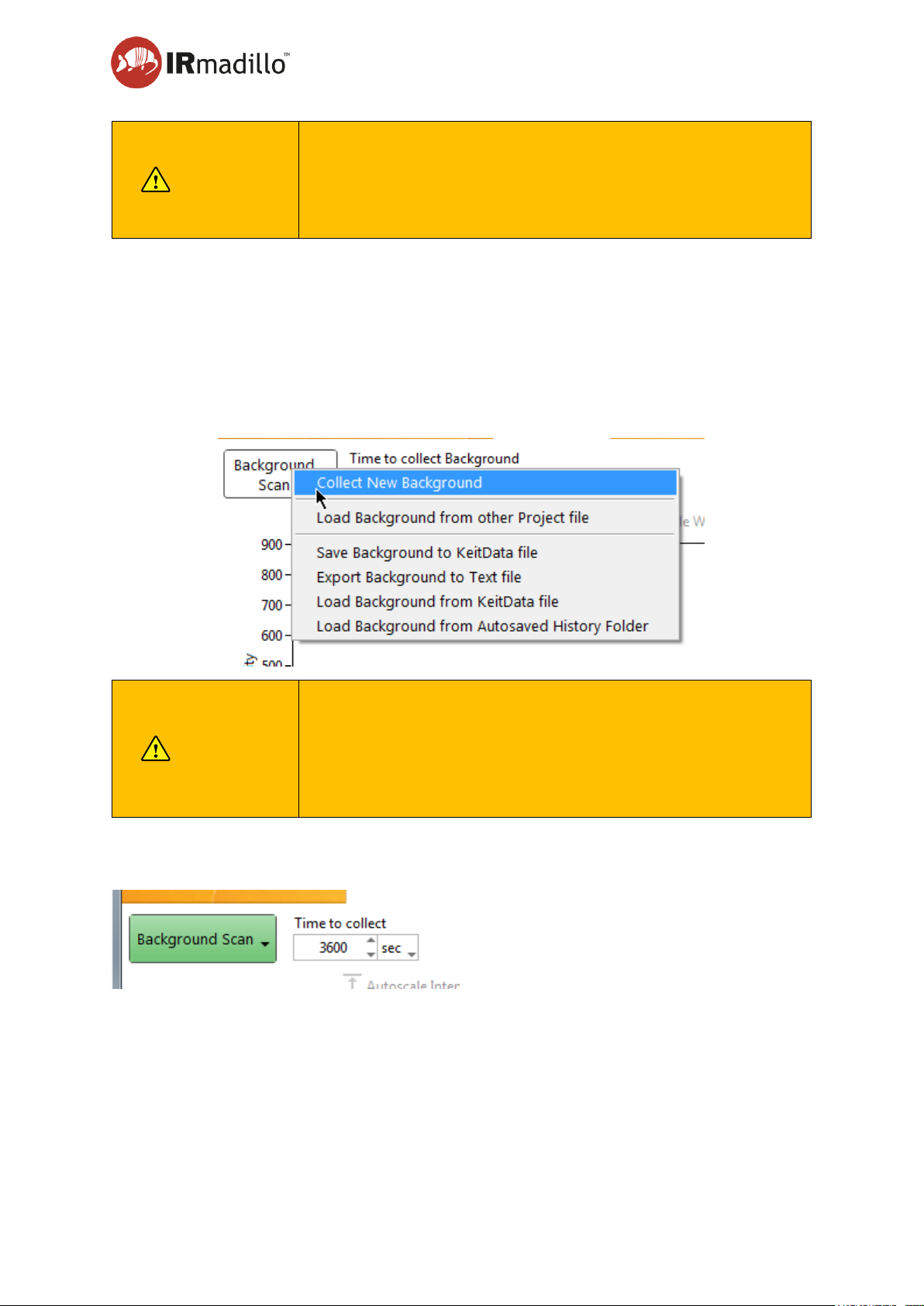
Step 4. Click on the Background Scan button and choose Collect Background.
NOTE
Because all subsequent scans will use the background scan
to calculate the absorbance, it is very important to scan for
as long as possible to optimise performance. The IRmadillo
does not need frequent new background scans to be
collected, so it is worth investing time in a high-quality
background scan at the beginning of use.
While the software is collecting a background scan, the Background Scan button will turn
green:
Note: the status bar located across the bottom of the screen will now contain text “Collecting
Background”.
You will not be able to change the view or start any other processes while background
collection is underway.
Page 29
User manual Page 29
www.keit.co.uk Using the system and software: DOC0535 (10 July 2019, 16:56)
Back to Table of Contents
5.2.4 Manual sample acquisition
If you wish to build up a library of only a few scans (for example to build a chemometric or
univariate model), then manually saving and naming each scan into the database is the most
effective method.
Step 1. Create a new (or open an existing) Manual Sample Acquisition project.
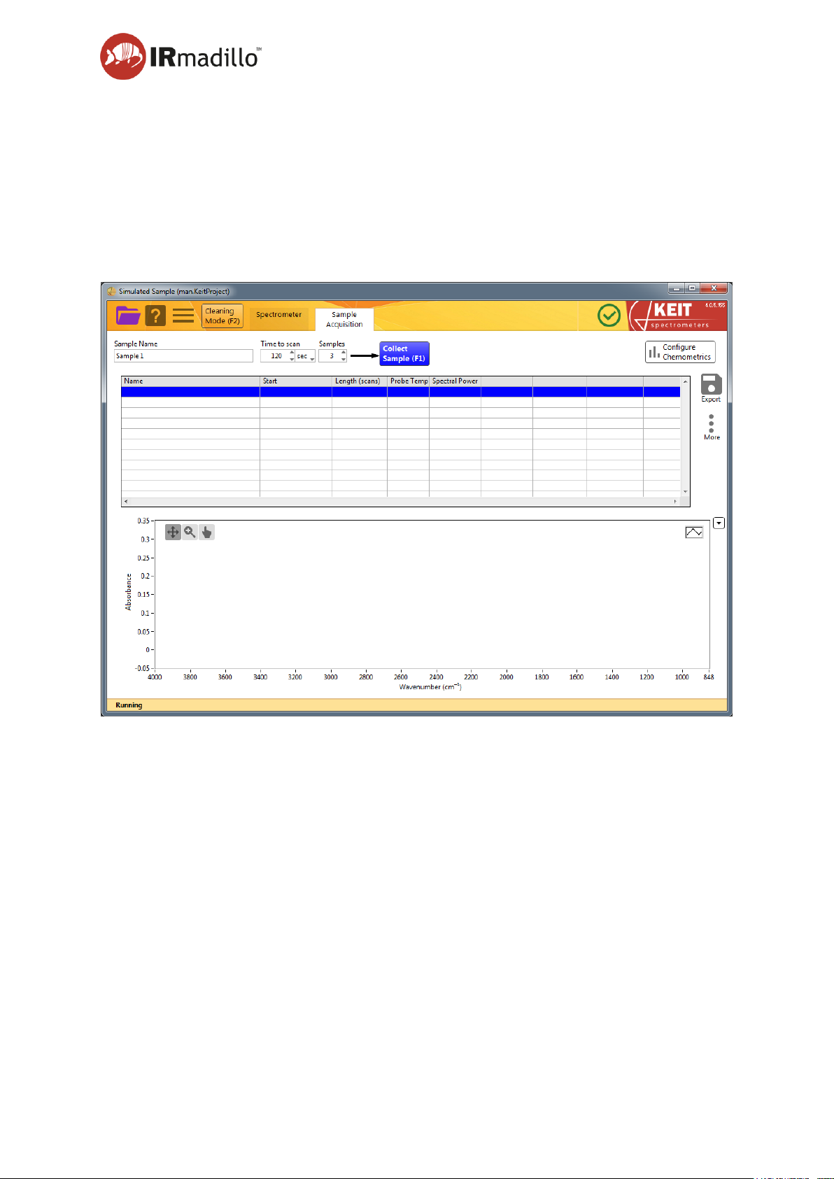
Step 2. Next click on the Sample Acquisition tab, which will give you the view shown in
Figure 1.
Figure 1: Sample Acquisition tab
Step 3. Insert the probe into the sample to be analysed (or fix the sample cell or flow cell as
per their instructions), ensuring that the ATR element is fully immersed.
Step 4. Enter a meaningful name into the Sample Name box, and check that the Time to
scan and Samples boxes are appropriate for your measurement requirements. We
recommend 120 s per sample and running each sample in triplicate, so chose 3.
Step 5. Press the “Collect Sample (F1)” button (or press F1) and wait for the sample
collection to complete – you should see a progress bar in the status bar at the
bottom of the application window. Once the measurement has been collected, a
new row will appear in the Data Panel which gives some information about
sample(s) that you have just collected.
Step 6. You can now remove the probe from the sample, thoroughly clean the probe and
ATR element, then insert the probe into the next sample and start the next
collection.
Page 30

User manual Page 30
www.keit.co.uk Using the system and software: DOC0535 (10 July 2019, 16:56)
Back to Table of Contents
5.2.5 Monitoring a reaction or process
The IRmadillo is designed for reaction and process monitoring. The Keit Spectrometer
Software (Keit Spec) saves data directly to a database as spectra are generated. This means
you can perform some interpretation during use with a chemometric model generated with
various external packages, as well as exporting the data into text files for further analysis.
Step 1. Ensure that you have collected a background scan.
Step 2. Insert the probe into the reaction vessel, pipework, or sample to be analysed,
ensuring that the ATR element is fully immersed and that no bubbles or air voids
are trapped when you fill the equipment with analyte.
Step 3. Create a new (or open an existing) Continuous Collection project and click on the
Configure Acquisition tab. Use the controls in this tab to adjust the settings so that
the instrument provides information that’s appropriate for your application.
Step 4. Refer to the descriptions of the various features and functions for further information
on how to configure the instrument.
Step 5. When you are ready to begin analysing a batch, click the New Batch button.
Step 6. Settings and data will be automatically saved to the project, there is no save button
and any configuration changes that you make will be recorded in the project.
Page 31
User manual Page 31
www.keit.co.uk Using the system and software: DOC0535 (10 July 2019, 16:56)
Back to Table of Contents
5.3 The Spectrometer tab
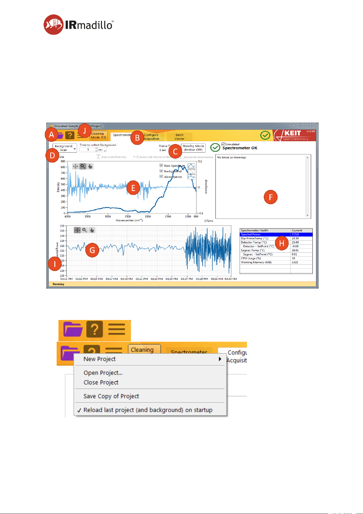
When you start the Keit Spectrometer Software (Keit Spec) you will see the Spectrometer
screen which provides information to help you set up the instrument and ensure that it is
working properly.
After starting the software wait a few seconds for the spectrometer to connect and for the
internal electronics to activate and the emitter to warm up. Diagnostics information is shown
in the panel at the right-hand side, and at the right-hand side of the tab bar.
Figure 2: The Spectrometer tab
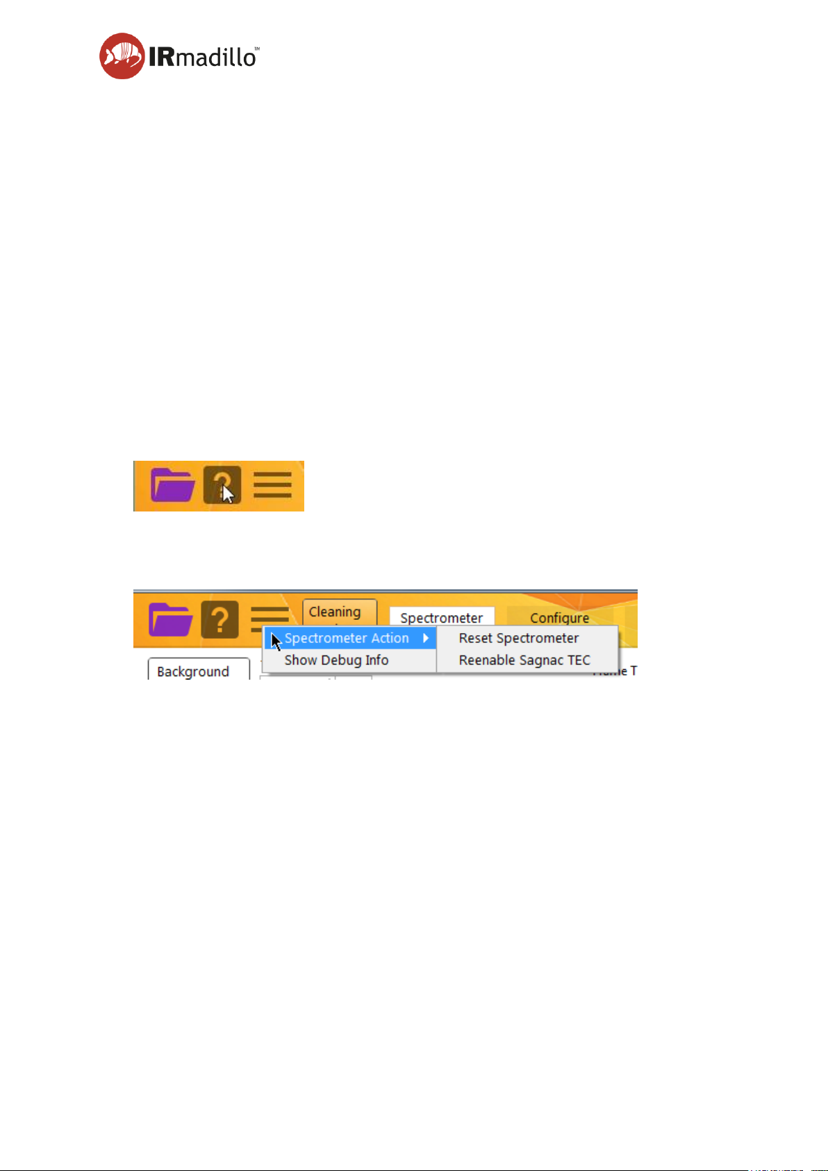
A. Menu control buttons
New Project:
Create a new project (either Manual Sample Acquisition or Continuous Collection)
Page 32
User manual Page 32
www.keit.co.uk Using the system and software: DOC0535 (10 July 2019, 16:56)
Back to Table of Contents
Open Project
Open a project from disk. The background spectrum that was collected within the project
will be loaded and replace the background that is currently present. Use the options on
the Background Scan button to load a different background spectrum.
Close Project
This option can be used to safely close a corrupt project.
Save Copy of Project
Saves a copy of the current project. This is the safest way to duplicate a project; copying
via your file browser may not copy your most recent data.
Reload last project (and background) on startup
Selecting this will turn on (or off) loading of the previous project when the software is
started. This is useful when the instrument is configured to operate without a directly
connected monitor/keyboard so that the software can begin collecting data immediately
after the hardware starts.
Context help will appear in a floating window to display information about the control or
display that the mouse pointer is currently hovering over. Use this feature to discover
more information about the controls on the software interface.
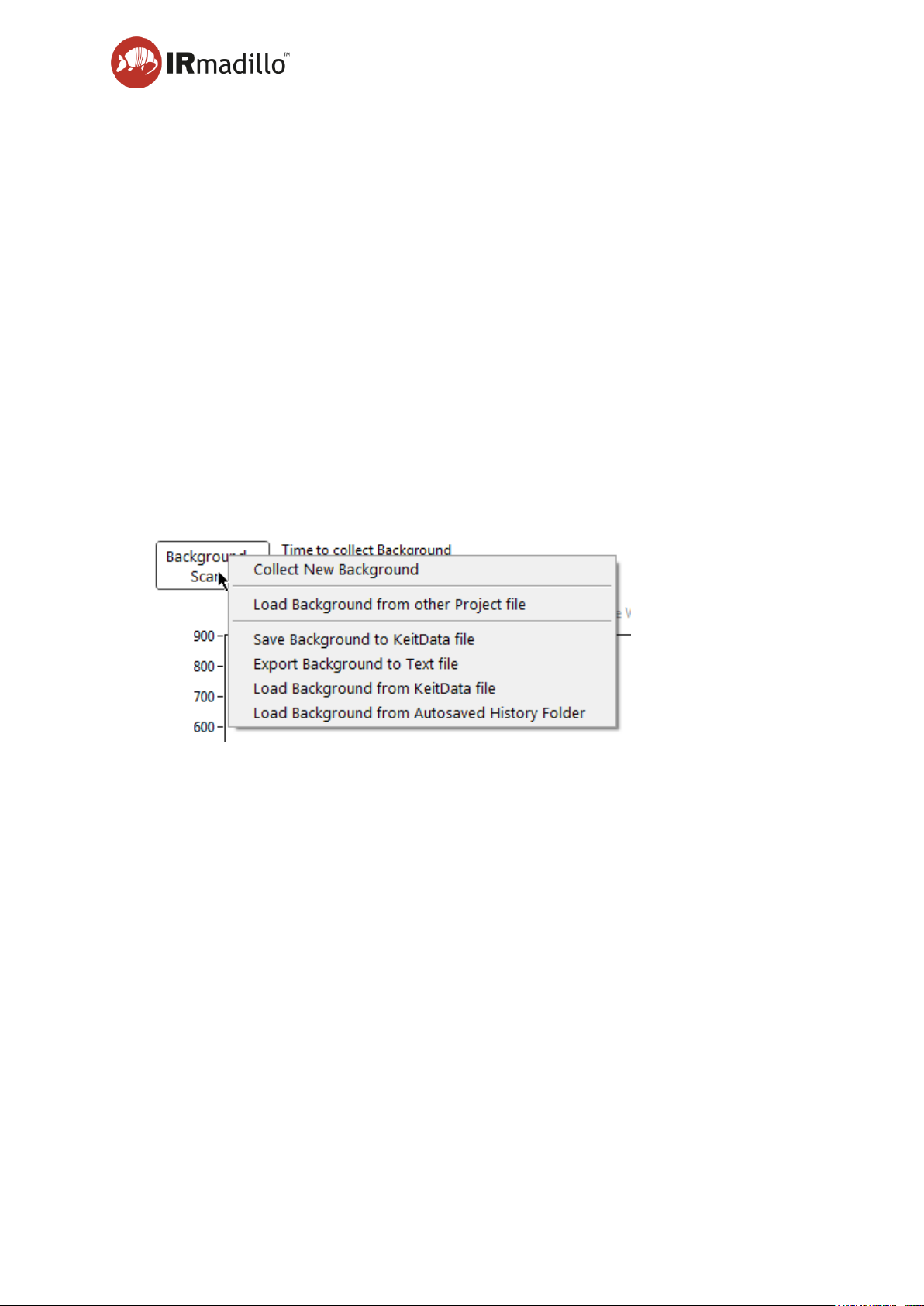
Spectrometer Action
Additional actions to be performed.
Reset Spectrometer
You may reset the spectrometer in the case that it appears to stop responding.
Reenable Sagnac TEC
If the specified operating temperature range of the instrument is exceeded, the thermal
stabilisation will shut down to protect the thermoelectric cooler (TEC). In this case, an
error will be flagged in the Data Integrity Errors panel. The TEC must be reenabled by
using this control.
Show Debug Info
Displays additional information in the main interface (i.e., return spectrum number, and
FFT processing time) which may be useful when diagnosing performance issues.
Page 33
User manual Page 33
www.keit.co.uk Using the system and software: DOC0535 (10 July 2019, 16:56)
Back to Table of Contents
B. Tab Bar
Once you configure the software for the operating mode that you wish to use, additional
tabs will appear to display information relevant to the configuration.
C. Operating Mode
The spectrometer may be switched to Standby Mode which disables the infrared light
source (emitter). The infrared light source in the spectrometer must be switched off during
sterilisation (SIP) cycles to prevent it overheating and changing its spectral
characteristics. This control is also available over the various automation interfaces
(Modbus, OPC-UA). Ensure that your sterilisation cycle does not exceed the
temperature rating of your probe.
When not in Standby Mode, the instrument will collect data. A spectrum is returned every
ten seconds.
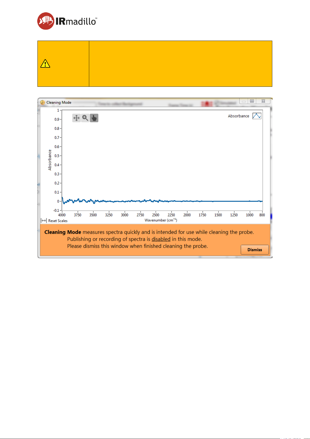
D. Background scan
FTIR requires the collection of a background spectrum (also called a reference or baseline
scan) before any absorption scans can be performed. This must be performed before the
probe is inserted into the reaction/process of interest.
Collect New Background
Collects a new background reference spectrum for the duration that is specified in the
Time to collect box.
Load Background from other Project File
Loads the background reference spectrum from another project file and saves it in the
current project marked as ‘Reference’.
Save Background to KeitData file
Allows you to save the background reference spectrum separately to the project file for
occasions when you’d like to be able to load it independently from the project data.
Export Background to Text file
Allows you to save the background reference spectrum in a human-readable format for
occasions when you’d like to carry out calculations using it.
Page 34

User manual Page 34
www.keit.co.uk Using the system and software: DOC0535 (10 July 2019, 16:56)
Back to Table of Contents
Load Background from KeitData file
Allows you to load the background reference spectrum from a separate file into the current
project.
Load Background from Autosaved History Folder
Background spectra are saved in a history folder for later re-use if necessary. You may
reload a background that you collected earlier by using this option.
E. Spectrum Display
This panel shows a live display of the current raw spectrum, the current absorption
spectrum, and the currently loaded background reference spectrum. You can use the
controls at the top-left corner to zoom in on a particular spectral region.
F. Data Integrity
The spectrometer continuously carries out internal diagnostics checks to ensure that the
measurements that are being collected can be trusted. Any conditions that could result in
the measurements being compromised are indicated in this panel.
One common error is that the instrument is still warming up. Refer to Section 7.7
Troubleshooting for more information and advice on how to interpret the data integrity
errors.
G. Health Statistics
Selected spectrometer diagnostics may be plotted over the past 15 minutes to allow the
instrument performance to be checked and any errors or warnings to be diagnosed. Select
a Spectrometer Health parameter from the list at the right-hand side (H) to plot its history.
H. Spectrometer Health
Relevant metrics on the spectrometer performance are displayed in this table. Selecting
a row in this table will cause the recent history of this metric to be plotted in the panel to
the left (G).
I. Measurement status bar
Information about the instrument will appear in this bar. This includes whether a
background spectrum has been loaded and whether the spectrometer is currently
scanning.
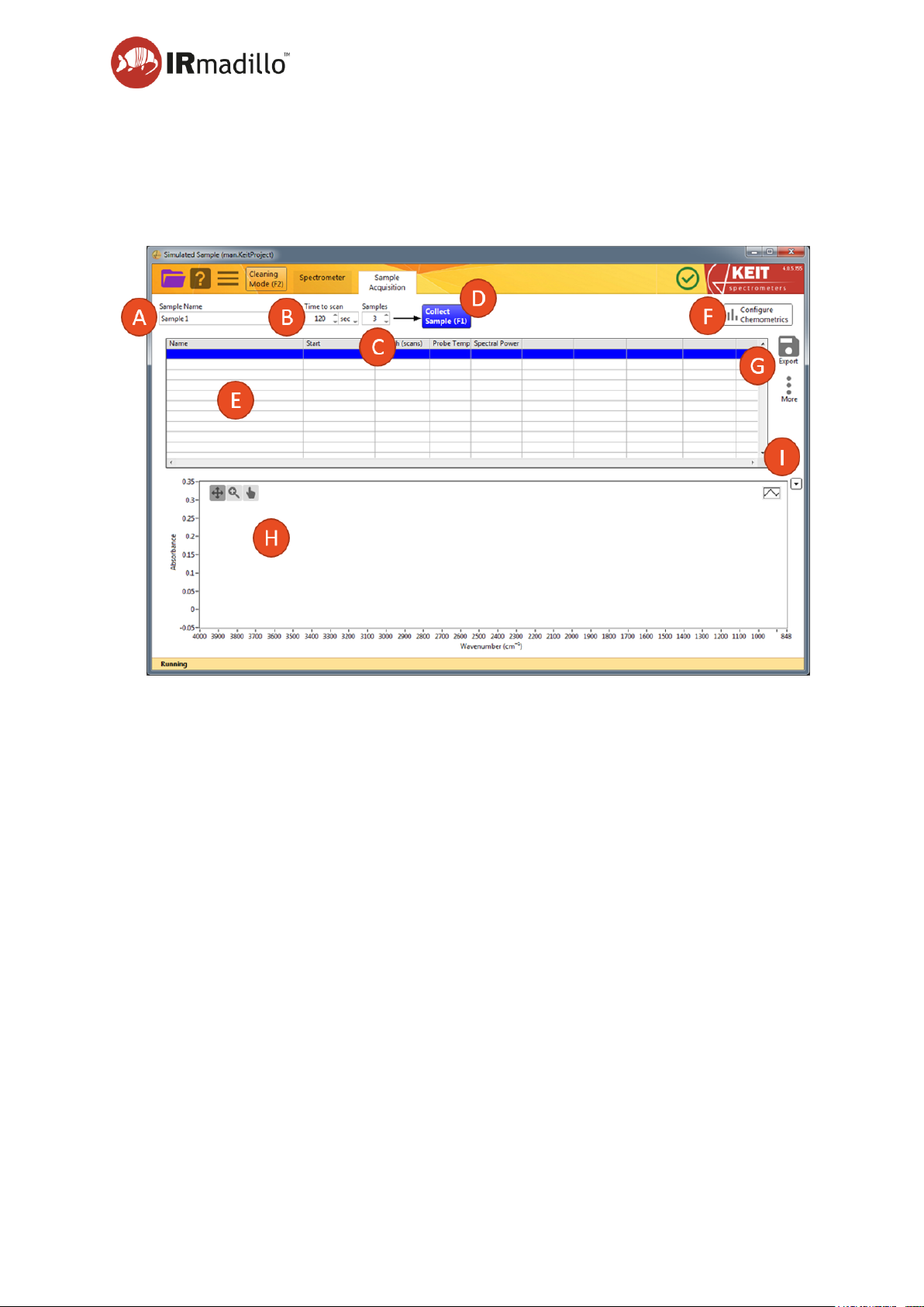
J. Cleaning Mode
You may wish to view the spectrum of the probe while cleaning to ensure the ATR element
is clean. The best way to do this is to put the spectrometer in Cleaning Mode, which
displays a new spectrum every two seconds (but does not allow the spectra to be
processed or saved). When the spectrometer is in Cleaning Mode, the Cleaning Mode
window appears, and the rest of the software is frozen. To return to Normal Running
Mode, either click Dismiss or close the Cleaning Mode window.
Page 35
User manual Page 35
www.keit.co.uk Using the system and software: DOC0535 (10 July 2019, 16:56)
Back to Table of Contents
CAUTION
The infrared light source in the spectrometer must be switched off
during sterilisation (SIP) cycles to prevent it overheating and
changing its spectral characteristics. This control is also available
over the various automation interfaces (Modbus, OPC-UA).
Ensure that your sterilisation cycle does not exceed the
temperature rating of your probe.
Page 36
User manual Page 36
www.keit.co.uk Using the system and software: DOC0535 (10 July 2019, 16:56)
Back to Table of Contents
5.4 Manual sample acquisition
Creating a new Manual Sample Acquisition project or opening a previously stored one will
cause the Sample Acquisition tab to appear in the tab bar. This project type will allow you to
collect individual spectra.
A. Sample name
Each sample that you collect can be named for later identification.
B. Time to scan
Use this box to specify the sampling duration for each spectrum. A typical spectral
acquisition is 120 s.
C. Samples
If you wish to make several measurements of a single sample, specify the number in the
Samples box. The instrument will make successive scans of the same sample.
D. Collect Sample
Click this button to begin sampling. As each measurement is collected, the Samples box
will automatically decrease to show the number that remain to be collected. Samples are
automatically saved to the current project – there is no separate ‘Save’ action.
E. Data panel
After each sample has been collected, information about it will appear in this panel. Each
line refers to a different measurement. To display the absorption spectrum for that sample
Page 37
User manual Page 37
www.keit.co.uk Using the system and software: DOC0535 (10 July 2019, 16:56)
Back to Table of Contents
in the spectrum panel (H), click on it. Multiple spectra may be selected by Ctrl-clicking
with the mouse.
F. Configure Chemometrics
The Keit Spec application contains analysis engines that can use chemometric models
generated by a number of software vendors. When a model is configured, a summary of
the results output is visible in the data panel (E).
This button opens a floating window to allow the chemometric model(s) to be configured
and adjusted. When the model is loaded or changed, the software will reprocess the whole
of the current batch against it. This may take a few minutes for a large batch or complex
model.
Refer to Section 5.8.1 on Chemometrics for further information about the chemometric
models.
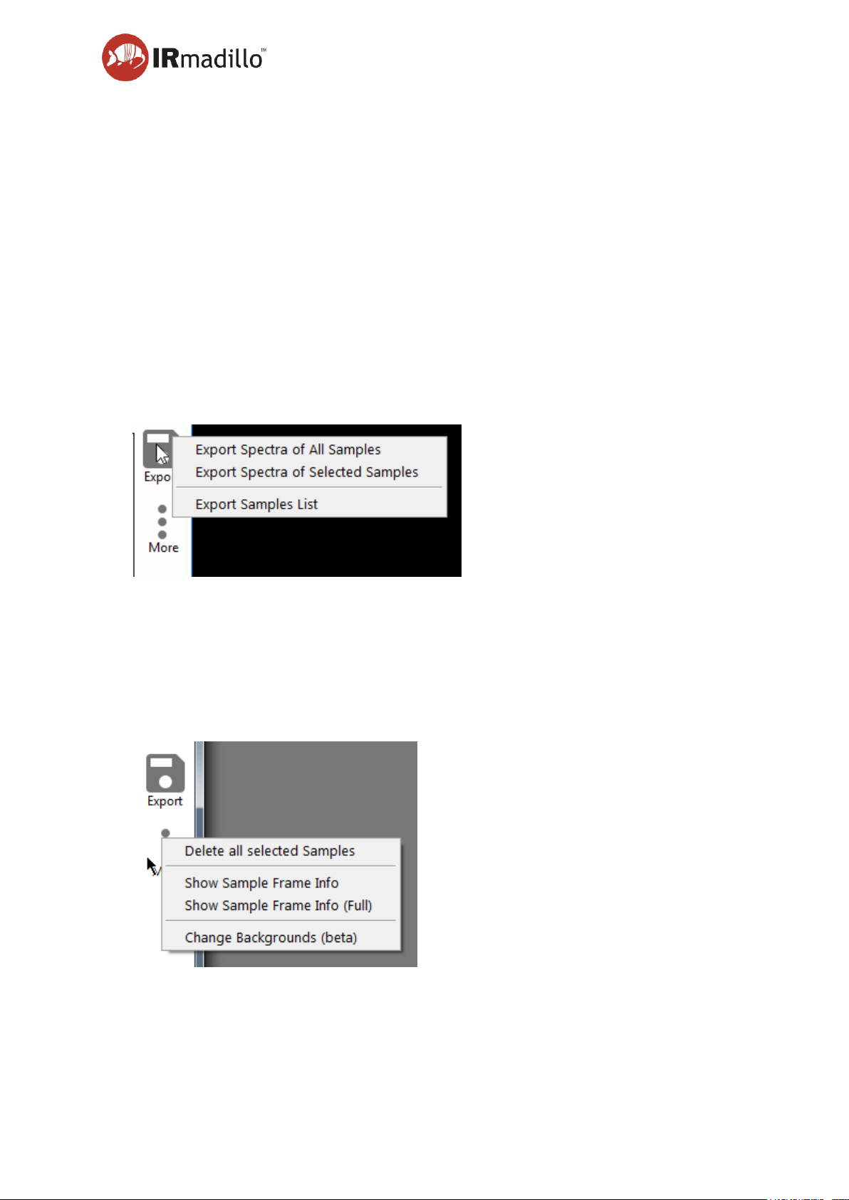
G. Export and More
Sample data may be exported to a text file for use with analytical software (such as
chemometric model-building software). Choose to either export spectra of all samples
shown in the data panel (E), or export spectra of selected samples. Export samples list
will export the data shown in the data panel (E), including chemometric data, but does not
export any spectra. You may select multiple samples by Ctrl-clicking on them in the data
panel (E).
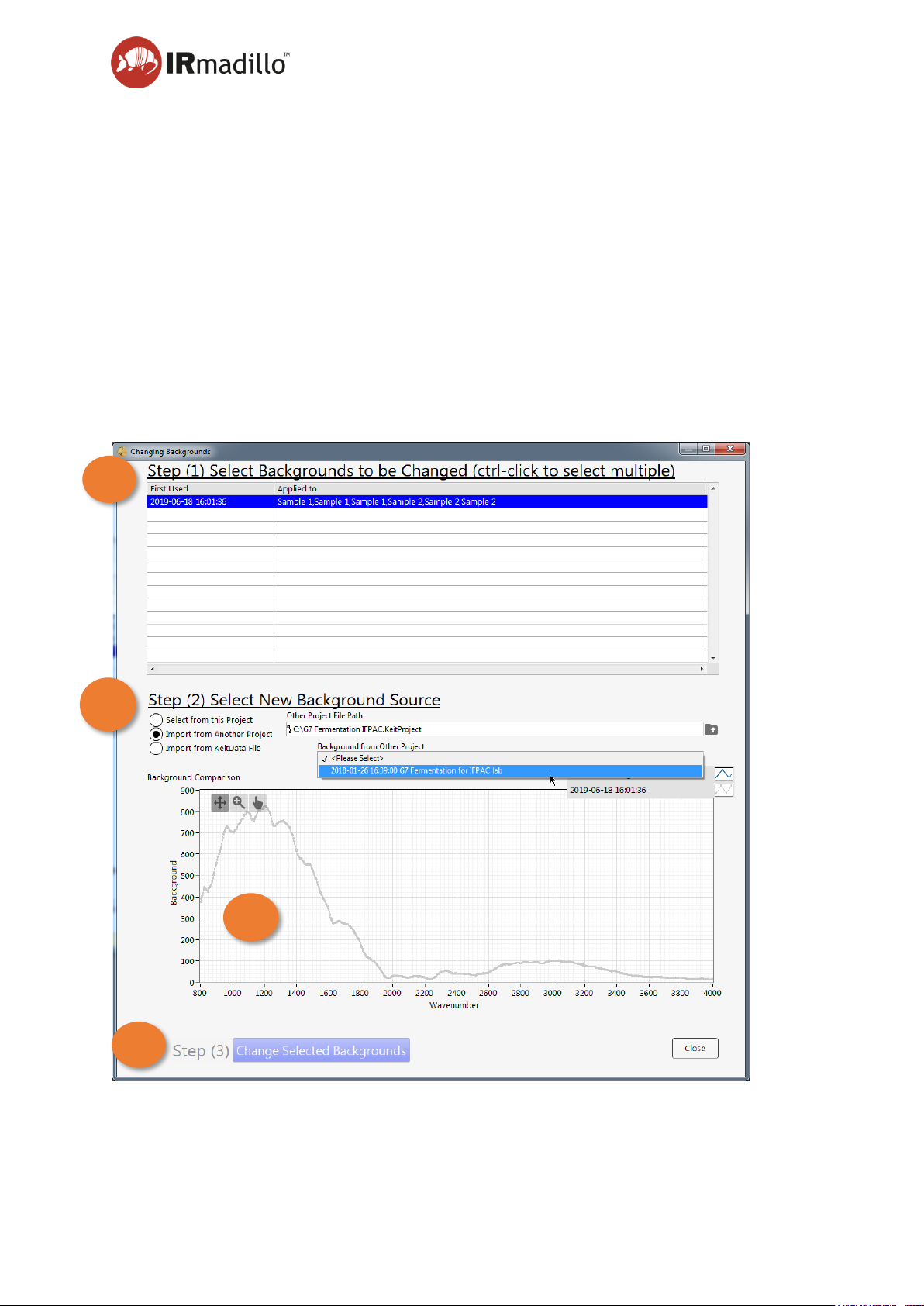
Delete all selected Samples
Deletes every spectrum that is selected in the data panel. You may select multiple
samples by Ctrl-clicking on them in the data panel (E).
Page 38
User manual Page 38
www.keit.co.uk Using the system and software: DOC0535 (10 July 2019, 16:56)
Back to Table of Contents
Show Sample Frame Info
Opens a floating window that displays diagnostic information about the spectrometer for
that Sample measurement. This is useful when diagnosing issues with your
measurements.
Show Sample Frame Info (Full)
Opens a floating window that displays extensive diagnostic information about the
spectrometer for that Sample measurement.
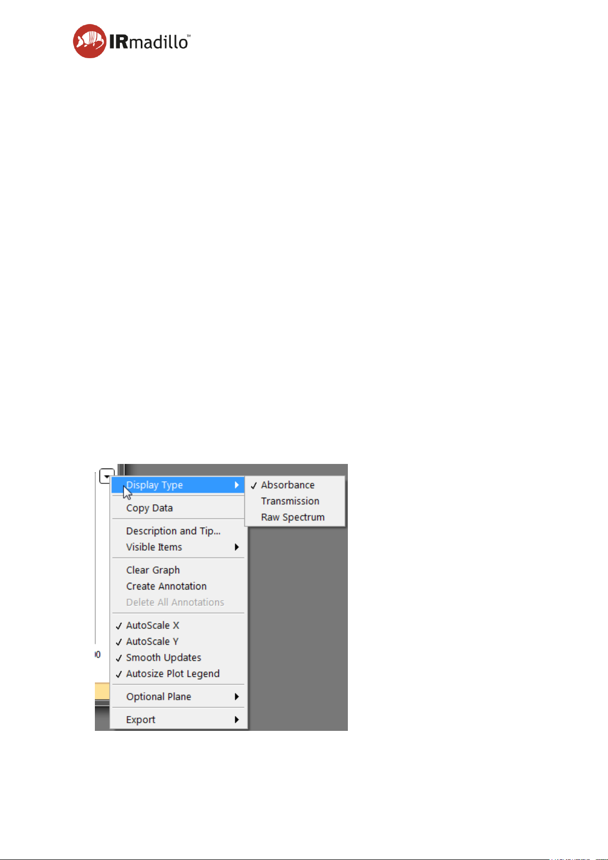
Change Backgrounds (beta)
Change the background spectra that the absorption data has been processed against.
This is useful if (for example) you discover that your probe was not clean when you
collected the original background spectrum, which would mean that all data collected
subsequently will be incorrect.
1
2
4
3
Page 39
User manual Page 39
www.keit.co.uk Using the system and software: DOC0535 (10 July 2019, 16:56)
Back to Table of Contents
Step 1. Backgrounds to be changed
Choose the spectra that you would like to replace the backgrounds for. They are
grouped by the background that is currently applied to them.
Step 2. Replacement background source
Select the source of the replacement background. This can be a different background
from the current project, a background from a different project, or an individual
spectrum from a KeitData file.
Step 3. Change Selected Backgrounds
Perform the recalculation of the absorption spectra using the replacement background
spectrum.
Step 4. Background Spectra Comparison
The original and replacement spectra are shown overlaid on this plot to allow
verification that the replacement makes sense. Check to make sure that you are happy
with the replacement spectrum before proceeding with the substitution.
H. Spectrum panel
The spectrum of the currently selected Sample(s) in the data panel (E) is displayed in this
panel. Several spectra may be overlaid by selecting multiple samples in the data panel
by Ctrl-clicking on multiple rows.
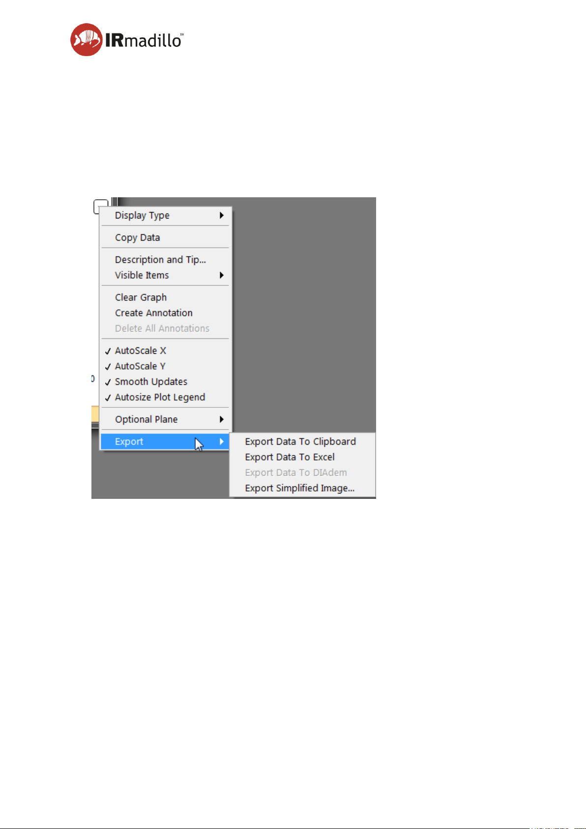
I. Graph panel display
Use this button to display a contextual menu to allow the plot display to be adjusted. This
menu can also be found by right-clicking on the plot.
Page 40
User manual Page 40
www.keit.co.uk Using the system and software: DOC0535 (10 July 2019, 16:56)
Back to Table of Contents
Display Type
The spectrum panel can display the current sample as either an Absorption, Transmission
or Raw spectrum (also known as single beam), depending on which is more useful to you.
Autoscale X/Y
The X and Y ranges of the plot are scaled to show the whole spectrum. If you wish to
concentrate on a smaller range, unchecking these options will prevent the plot rescaling
each time a new sample is displayed.
Export
Allows the data that is currently displayed in the spectrum panel (H) to be exported to a
range of different file types, including copying it directly to the Windows clipboard, an
Excel spreadsheet (requires a working copy of Microsoft Excel to be installed), or as an
image.
Page 41
User manual Page 41
www.keit.co.uk Using the system and software: DOC0535 (10 July 2019, 16:56)
Back to Table of Contents
5.5 Configure acquisition
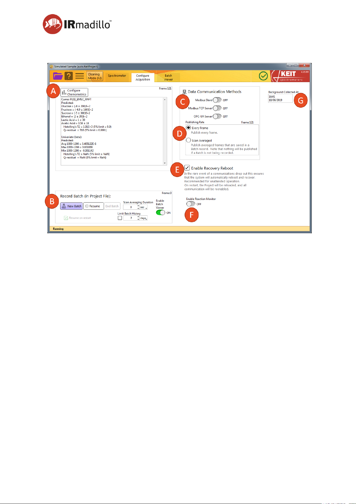
A. Chemometrics Panel
The Keit Spec application contains analysis engines that can use chemometric models
generated by a number of software vendors. When a model is configured, a summary of
the results output is visible in this panel.
Configure Chemometrics
This button opens a floating window to allow the chemometric model(s) to be configured
and adjusted. When the model is loaded or changed, the software will reprocess the whole
of the current batch against it. This may take a few minutes for a large batch or complex
model.
Refer to Section 5.8.1 on Chemometrics for further information about the chemometric
models.
B. Record Batch (in project file)
In a continuous collection project, data may be collected in batches. Each project must
contain at least one batch. Use the controls in this panel to control how the batches are
collected.
New Batch
Click this button to begin collecting a new batch. The software will prompt for the batch
name or identifier and then begin collecting spectra based on the settings in this panel.
Page 42

User manual Page 42
www.keit.co.uk Using the system and software: DOC0535 (10 July 2019, 16:56)
Back to Table of Contents
Resume
If your project contains a batch that has already been started and then paused, clicking
the ‘Resume’ button will restart the collection without prompting for a new batch name.
End Batch
Stops recording the current batch. You can resume collection with the Resume button, or
start a new batch.
Scan Averaging Duration
The spectrometer returns spectra every 10 seconds by default. It is highly recommended
to change this number to 120 s for most processes.
Limit Batch History
If your process runs for a particularly long time you may wish to only keep a portion of the
historical data. Enabling this box allows you to choose how long to retain information (the
default is 7 days). Data older than the specified time will be deleted from the local hard
drive. This option is more useful for continuous processes than batch processes.
Resume on startup
Checking this box will ensure that the instrument resumes saving data when the software
starts up.
Enable Batch Viewer
The Batch Viewer displays real-time and historical information about the various batches
that you have recorded in the current project.
C. Data Communication Methods
Additional functions and features may be turned on as appropriate for your process
monitoring application. Turning on each of these options adds a new tab to the tab bar.
Information about these features can be found in the documentation for that tab.
Modbus Slave
The instrument can communicate with a plant control system using Modbus RTU. Turn
this feature on to enable control over Modbus RTU.
Modbus TCP Server
The instrument can communicate with a plant control system using Modbus TCP over
Ethernet. Turn this feature on to enable control over Modbus TCP.
OPC-UA Server
The instrument can communicate with a plant control system using OPC-UA (subject to
purchase of a separate OPC server license). Turn this feature on to enable control over
OPC-UA.
D. Publishing Rate
This controls how quickly results are published via OPC or Modbus.
Page 43

User manual Page 43
www.keit.co.uk Using the system and software: DOC0535 (10 July 2019, 16:56)
Back to Table of Contents
Every Frame
This publishes every spectrum that the spectrometer returns (one every 10 seconds).
Scan Averaged
This publishes the averaged spectra that are stored to the Project File.
E. Enable Recovery Reboot
The software can recover from communications issues (e.g., if the hardware link needs
to be reset). The system will attempt to reset the communications link between the
controller and spectrometer if it should become corrupt. If this does not resolve
communications issues, the software will restart the computer if this box is checked. The
computer will automatically log the user back in and restart the spectrometer control
software.
F. Reaction Monitor
Displays real-time information about recent spectra. Control limits can be applied to
various spectroscopic values, and alarms asserted when the process deviates beyond
the limits.
G. Last Background
Displays the date and time that the current background spectrum was collected.
Page 44
User manual Page 44
www.keit.co.uk Using the system and software: DOC0535 (10 July 2019, 16:56)
Back to Table of Contents
5.6 Batch viewer
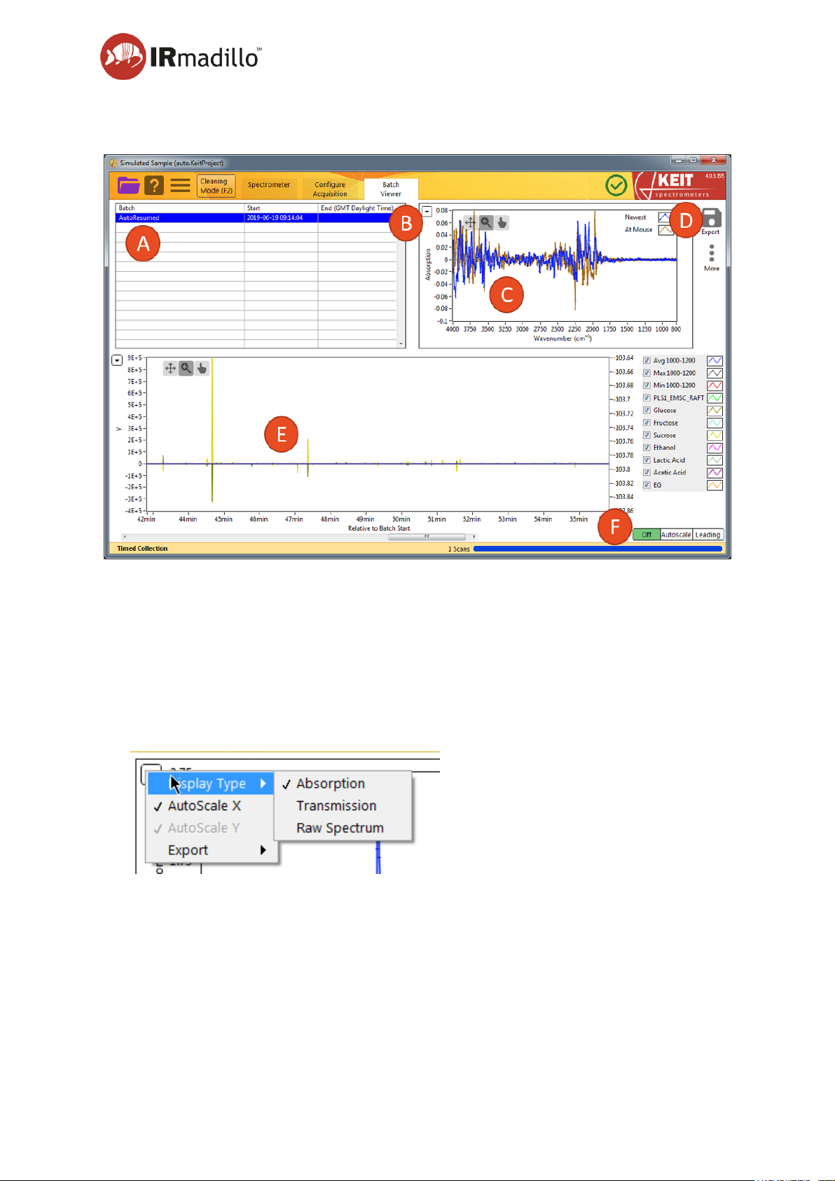
A. Batch panel
This panel contains a list of the batches that have been stored in the current project.
Select a batch to display its history in the Trends panel (E) and relevant spectra in the
spectrum panel (C).
B. Spectrum additional actions
Use this button to display a contextual menu to allow the plot display to be adjusted. This
menu can also be found by right-clicking on the plot.
Display Type
The spectrum panel can display the current sample as either an Absorption, Transmission
or Raw spectrum, depending on which is more useful to you.
Autoscale X/Y
The X and Y ranges of the plot are scaled to show the whole spectrum. If you wish to
concentrate on a smaller range, unchecking these options will prevent the plot rescaling
each time a new sample is displayed.
Page 45
User manual Page 45
www.keit.co.uk Using the system and software: DOC0535 (10 July 2019, 16:56)
Back to Table of Contents
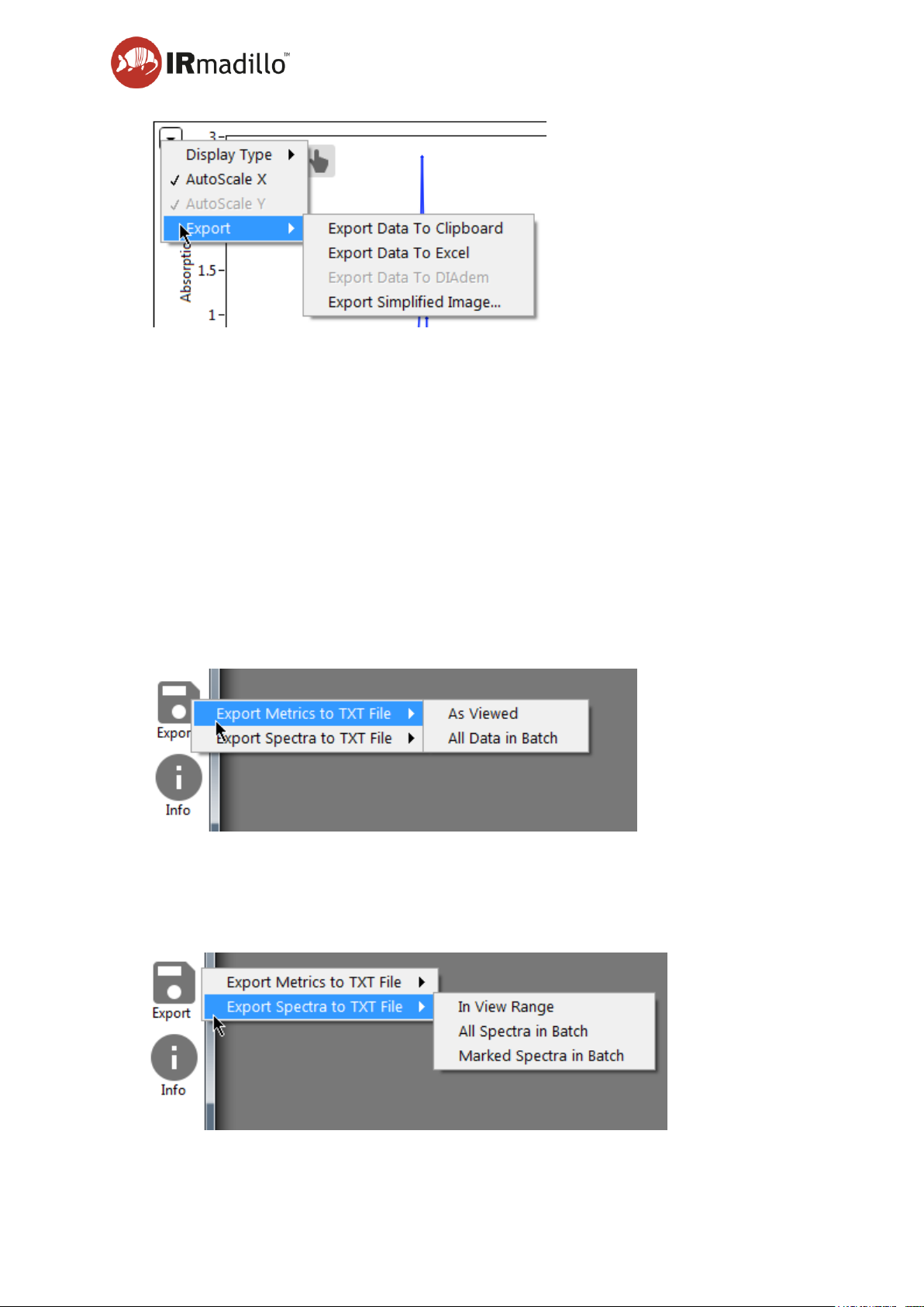
Export
Allows the data that is currently displayed in the spectrum panel to be exported to a range
of different file types, including copying it directly to the Windows clipboard, an Excel
spreadsheet (requires a working copy of Microsoft Excel to be installed), or as an image.
C. Spectrum plot
This panel shows the current live spectrum in the batch, and the spectrum under the
mouse pointer in the Trends panel (E). If the batch that is selected is not being updated
(i.e., another batch is currently being recorded to), the display will show the most recent
spectrum in the batch in addition to the spectrum under the mouse pointer.
Use the display tools to adjust the display to zoom in on specific regions and move the
plot view around.
D. Export and Info
Export Metrics to TXT file
The current chemometric model outputs may be exported to a text file for analysis or
presentation with other software. You may choose to export only the data that is currently
displayed in the Trends panel (as Viewed) or all the data in the batch.
Page 46
User manual Page 46
www.keit.co.uk Using the system and software: DOC0535 (10 July 2019, 16:56)
Back to Table of Contents
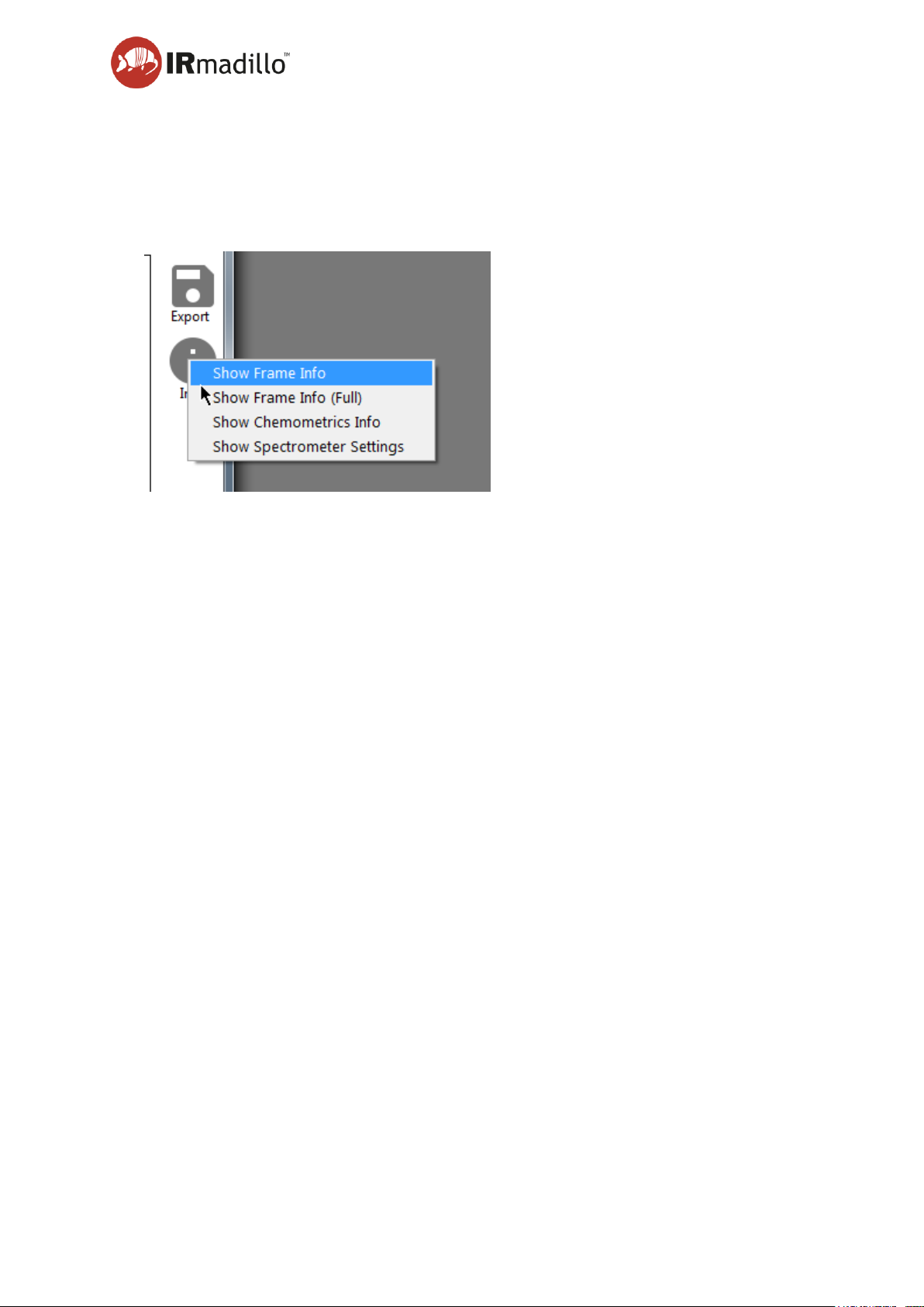
Export Spectra to TXT file
The spectra in the current batch may be exported to a text file for analysis or presentation
with other software. You may choose to export only the data that is currently displayed in
the Trends panel (as Viewed), all the data in the batch, or only spectra that have been
marked. See the Trends panel (E) for information about marking spectra.
For each spectrum, diagnostics information is available to assess the instrument or
calculation performance.
Show Frame Info
Opens a floating window that displays diagnostic information about the spectrometer for
that Sample measurement.
Show Frame Info (Full)
Opens a floating window that displays extensive diagnostic information about the
spectrometer for that Sample measurement.
Show Chemometrics Info
Displays the model output from the current set of calculation parameters for the currently
displayed point on the trends panel (E).
Show Spectrometer Settings
Displays a floating window with information about the spectrometer, including software
version numbers and serial numbers.
E. Trends Panel
Recent history of the chemometric model output appears in the Trends panel (NB If there
is no chemometric model, this panel will appear blank). The rolling output for each of the
species/parameters is displayed with the quantity (Y) displayed on the vertical axis and
time on the horizontal axis. Hovering the mouse over the panel will cause the spectrum
related to that point in time to be displayed in the Spectrum panel (C).
Page 47
User manual Page 47
www.keit.co.uk Using the system and software: DOC0535 (10 July 2019, 16:56)
Back to Table of Contents
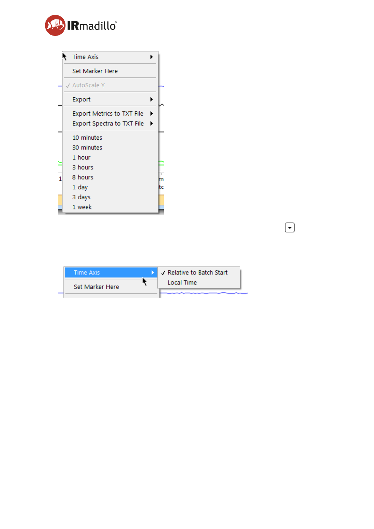
Right-clicking on the Trends panel, or clicking on the context menu button ( ) at the top
left causes a contextual menu to appear.
Time Axis
The time axis can display local time, or the time since the selected batch was started.
Set Marker Here
Individual spectra can be marked to allow the trends and analysis to be correlated with
other external events (e.g., the addition of new reactants to the process, or the adjustment
of some parameters). Hover the mouse over the spectrum/time period that you want to
mark, and then right-click and choose Set Marker Here. Enter an appropriate name into
the dialog that appears and click OK.
Export
Export allows the data that is currently displayed in the spectrum panel to be exported to
a range of different file types, including copying it directly to the Windows clipboard, an
Excel spreadsheet (requires a working copy of Microsoft Excel to be installed), or as an
image.
Export Metrics to TXT file
The current chemometric model outputs may be exported to a text file for analysis or
presentation with other software. You may choose to export only the data that is currently
displayed in the Trends panel (as Viewed) or all the data in the batch.
Page 48
User manual Page 48
www.keit.co.uk Using the system and software: DOC0535 (10 July 2019, 16:56)
Back to Table of Contents
Export Spectra to TXT file
The spectra in the current batch may be exported to a text file for analysis or presentation
with other software. You may choose to export only the data that is currently displayed in
the Trends panel (as Viewed), all the data in the batch, or only spectra that have been
marked. See the Trends panel (E) for information about marking spectra.
Time Periods
The time period over which data are displayed may be adjusted as appropriate for the
current batch measurement.
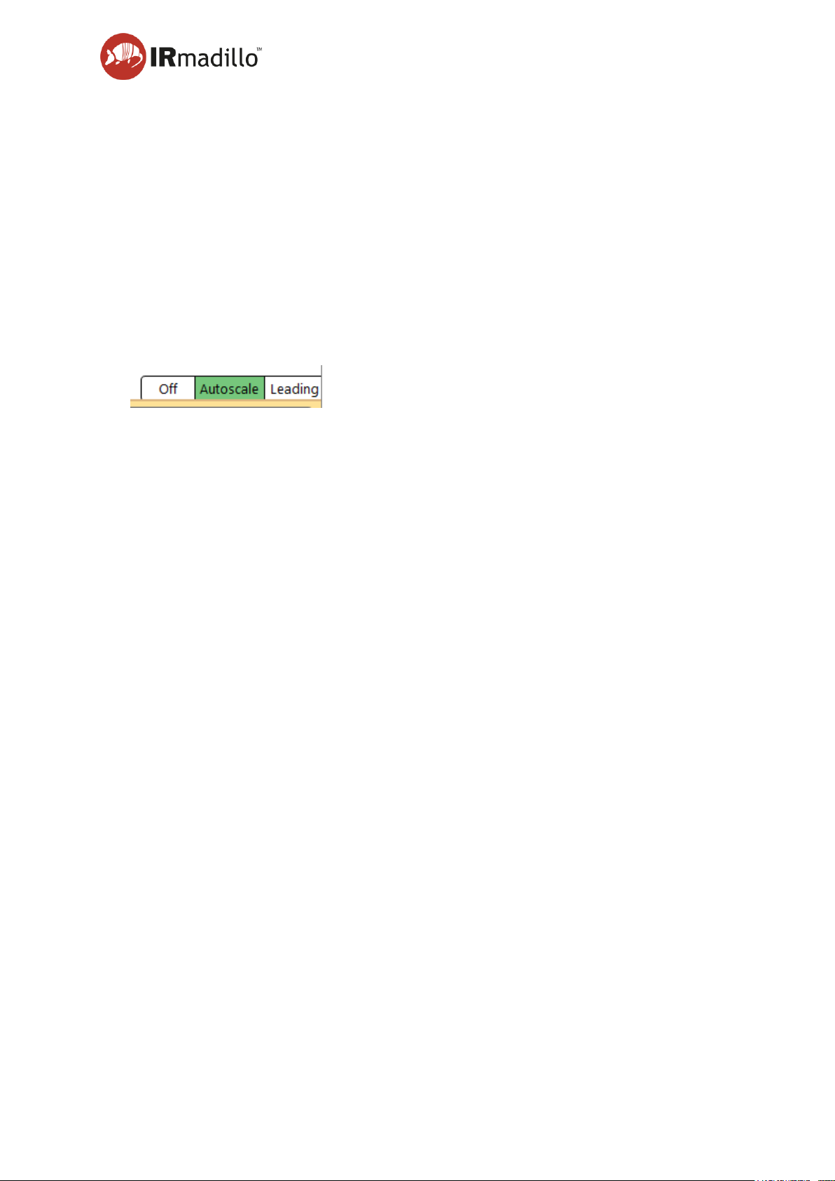
F. Autoscale Range
By default, the Trends panel shows all the data in the current batch.
Off holds the current view range unchanged as data is updated.
Autoscale (Default) shows the whole batch data.
Leading shows the most recently collected data, with history defined by the range set on
the context menu (right-click on the plot).
Page 49
User manual Page 49
www.keit.co.uk Using the system and software: DOC0535 (10 July 2019, 16:56)
Back to Table of Contents
5.7 Reaction monitor
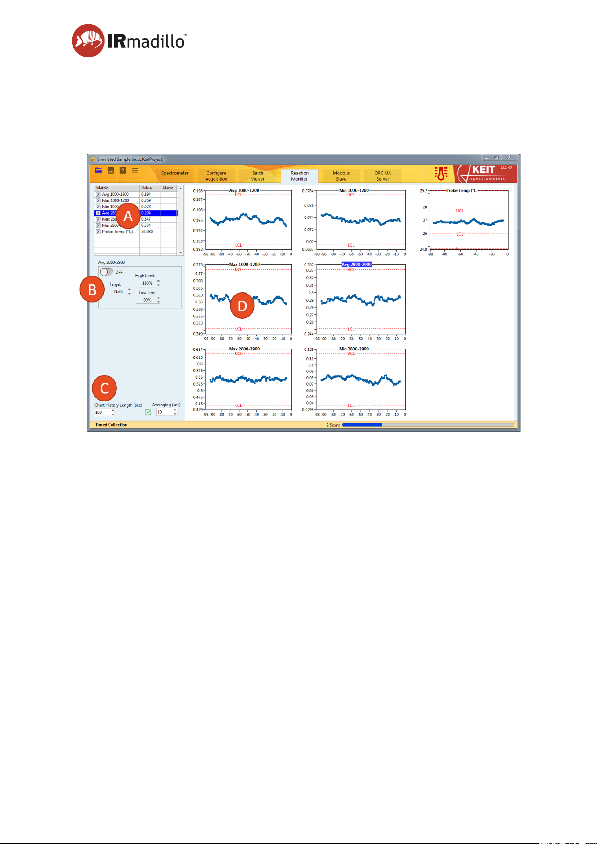
Reaction monitor displays simple control charts of the parameters in your current chemometric
model. This allows visualisation of when a process or parameter strays outside its specified
limits.
A. Metrics Panel
The currently available metrics are displayed in a table. Select one to highlight its plot in
the display panel (D) and its alarms in the alarm settings panel (B).
B. Alarm settings panel
Alarms may be defined to highlight when a process has deviated from its expected range.
Select the metric that you want to set an alarm against in the Metrics panel (A) and turn
the Alarm on with the toggle. Set the target value to the absolute value that is expected,
and then set the limits based on a percentage of the target value.
The alarm is indicated in the ALARM column in the Metrics panel.
C. Chart Display Settings
Chart History Length (sec)
Adjusts the history duration on the monitoring plots.
Page 50

User manual Page 50
www.keit.co.uk Using the system and software: DOC0535 (10 July 2019, 16:56)
Back to Table of Contents
Averaging
When the checkbox is checked, the measurements are averaged to smooth out noise and
displayed in the plots in the display panel (D). The Averaging (sec) box adjusts the amount
of averaging applied.
D. Display panel
The various parameters that are being monitored are displayed in this panel with the
various control limits shown (if specified), based on the alarm settings for each parameter.
Page 51
User manual Page 51
www.keit.co.uk Using the system and software: DOC0535 (10 July 2019, 16:56)
Back to Table of Contents
5.8 Configure chemometrics
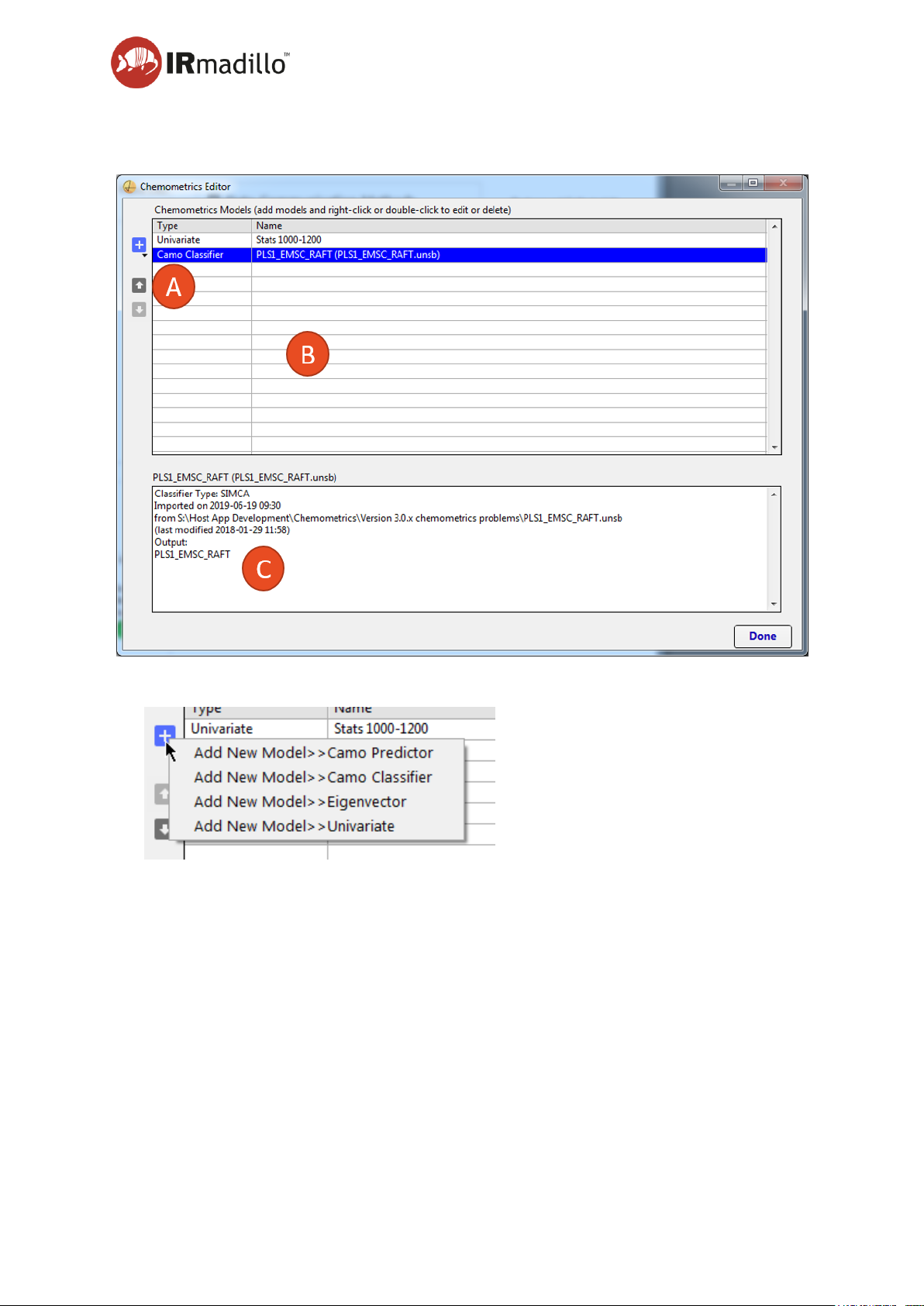
A. Add model button
New chemometric models may be added with the Add model button. Keit Spec supports
most Camo Analytics’ Unscrambler, Eigenvector Solo or PLS Toolbox, and Univariate
models; for more details, see Section 5.8.1 Supported model types, below. Camo
Analytics’ Unscrambler is supported by incorporating the Unscrambler X Engine version
10.4.1.
The Camo Analytics or Eigenvector tools are required to build models that can then be
imported to the Keit software. Export the model file from your analysis software, and then
load it into the Keit software. The data stored in the current batch or project will be reanalysed against the model and the results presented in the Trends panel of the Batch
viewer tab (for continuous project), or the Data panel of the Sample Acquisition tab (for
manual projects). If you are using Modbus or OPC-UA to connect to a plant’s distributed
control system (DCS), the results of the models will be available over those interfaces for
Page 52
User manual Page 52
www.keit.co.uk Using the system and software: DOC0535 (10 July 2019, 16:56)
Back to Table of Contents
the current live spectrum. No scaling is applied to the results since they are represented
as floating point numbers over Modbus and OPC.
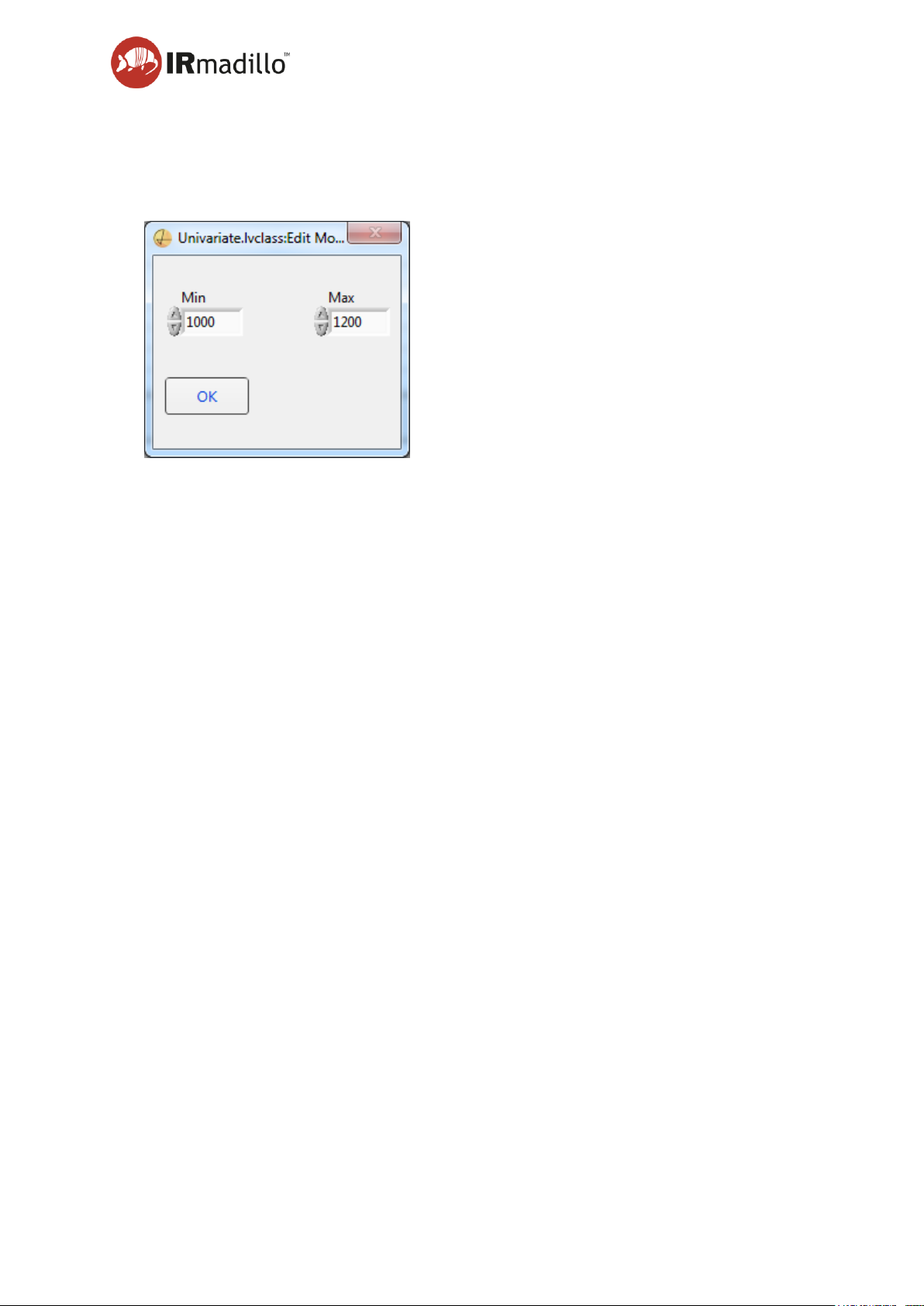
Univariate models are based on peak height tracking and are useful as a method to
monitor simple reactions and spectra.
Enter the wavenumber range that is appropriate for your spectrum into the Min and Max
boxes and click OK.
B. Current Models Panel
The current chemometric models that are loaded are shown in the dialog box. Click on a
row in the table to show the current outputs from that model in the Statistics panel (C).
Use the arrow buttons at the left-hand side to adjust the order of the models, which
changes their display order in the results output.
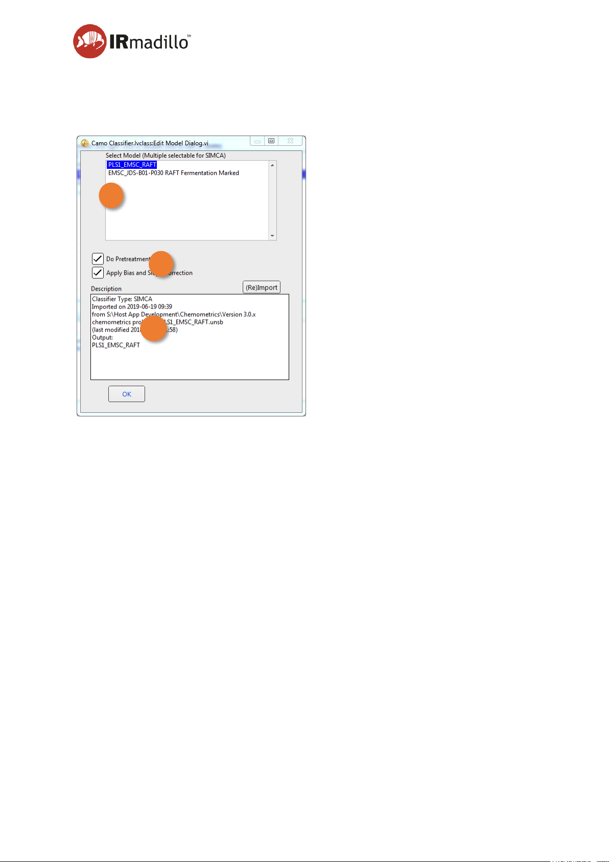
Some Chemometric models may be adjusted once they have been loaded. Double click
on the model in the list to edit parameters.
C. Statistics Panel
The model statistics associated with the chemometric model that is selected in the Current
Models panel are shown in this panel.
Page 53

User manual Page 53
www.keit.co.uk Using the system and software: DOC0535 (10 July 2019, 16:56)
Back to Table of Contents
5.8.1 Supported model types
Keit Spec currently supports the following types of models and pretreatments:
Eigenvector:
• Normalisation
• Smoothing
• SNV
• MSC
• Mean centring
• Reduced ranges
• Models exported with placeholders
Camo Analytics Predictor:
• Normalisation
• Smoothing
• MSC and EMSC
• OSC
• First and Second Derivatives
• SNV
• Raw
• NIPALS
• PLS2
• SVR (including radial or polynomial transforms)
• Reduced ranges
Camo Analytics Classifier:
• LDA
• PCA
• SVM
The following types of models are not supported:
• Eigenvector models which use Derivative pretreatments
• Camo Classifier SIMCA models
• Models in which the range of data has been restricted before importing into
Eigenvector or Camo
• Models which include non-wavenumber data (e.g. the dip probe temperature)
Keit Spec can support Camo models which have been exported in either Full or Short
Prediction mode, but please note that Short Prediction mode does not support either
Hotelling’s T
2
or Q-residuals. These values will be shown as NaN in Keit Spec.
It is possible to apply multiple models or pretreatments sequentially in Camo, but it may be
necessary to export the whole Camo file and then select the final model from within Keit Spec.
See Section 5.8.3 Common chemometrics errors.
Page 54
User manual Page 54
www.keit.co.uk Using the system and software: DOC0535 (10 July 2019, 16:56)
Back to Table of Contents
5.8.2 Editing Camo model settings
You may choose whether to apply the pre-treatments and bias correction to Camo models
once they have been imported. Double-click on the model in the Current Models Panel.
A. Camo model files may contain more than one model, so select the model that you wish to
adjust.
B. The pre-treatments may be turned off to use the raw spectral data without baseline
correction or other treatments.
C. Information about the current model, including how it was built, when it was imported and
the file path that it was loaded from.
A
B
C
Page 55

User manual Page 55
www.keit.co.uk Using the system and software: DOC0535 (10 July 2019, 16:56)
Back to Table of Contents
5.8.3 Common chemometrics errors
Issue
Possible Cause
Potential Solution
Error 5115 occurred at Camo:
ERR_SUBMODEL_ERROR:
Error in a sub-model file such
as MSC/EMSC/OSC.
Multiple models have been
applied in Camo, but not all
the models have been
loaded into Keit Spec.
Import the whole
Unscrambler file into Keit
Spec, then select the
correct model from within
Keit Spec (see Section 5.8.2
Editing Camo model
settings).
Error 5151 occurred at
Camo: ERR_INPUT_ERR:
Some error in data used for
prediction, e.g. column
dimension mismatch.
Classifier models: The
spectra on which the model
was built has a different
wavenumber range to that
used by the spectrometer.
Rebuild the model using the
full wavenumber range.
Models return 0, NaN or no
results
One or more unsupported
models or pretreatments
have been used.
Choose a different model or
pretreatment. Refer to
Section 5.8.1 Supported
model types.
A Camo Classifier model
has been imported as a
Camo Predictor model or
vice versa.
Ensure that the correct
model type has been
imported.
Predictions that do not
match those in Unscrambler,
PLS_Toolbox or Solo
Wavenumber axis has been
inverted.
Rebuild the models with the
correct wavenumber axis.
One or more unsupported
models or pretreatments
have been used.
Choose a different model or
pretreatment. Refer to
Section 5.8.1 Supported
model types.
Page 56
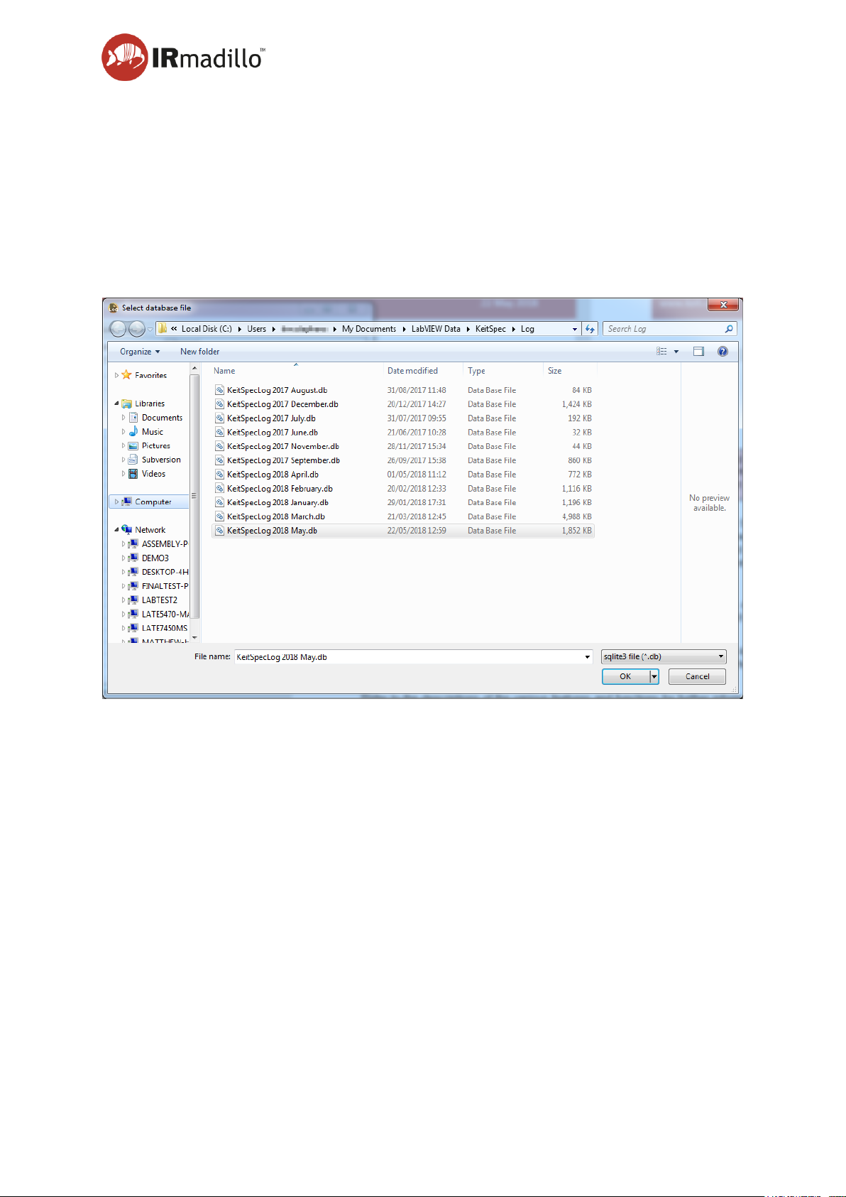
User manual Page 56
www.keit.co.uk Using the system and software: DOC0535 (10 July 2019, 16:56)
Back to Table of Contents
5.9 Log viewer
The Keit Spec application logs changes that are made to its configuration, various events and
performance information about the spectrometer. Logs are also useful in case you need to
contact Keit for service assistance. A log file is created for each month that the instrument is
operating.
The log viewer software is installed on your computer when you install the main Keit Spec
application. When you start the Log Viewer, it will prompt for you to choose the log file that
you wish to view.
Choose the log file that you want to view, and the main application window will appear.
Page 57
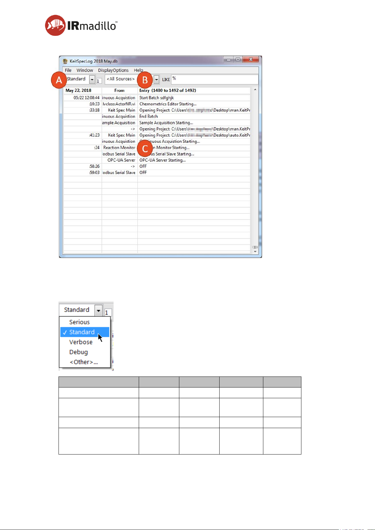
User manual Page 57
www.keit.co.uk Using the system and software: DOC0535 (10 July 2019, 16:56)
Back to Table of Contents
A. Log levels
There are a series of different log levels that are recorded. Use the drop-down to choose
the most appropriate level of detail to the task that you want to perform.
Log Level
Serious
Standard
Verbose
Debug
Instrument Errors
X X X
X
Application events
(starting/stopping)
X X
X
Settings Changes
X
X
Settings configuration
errors, non-fatal errors
and warnings.
X
Page 58
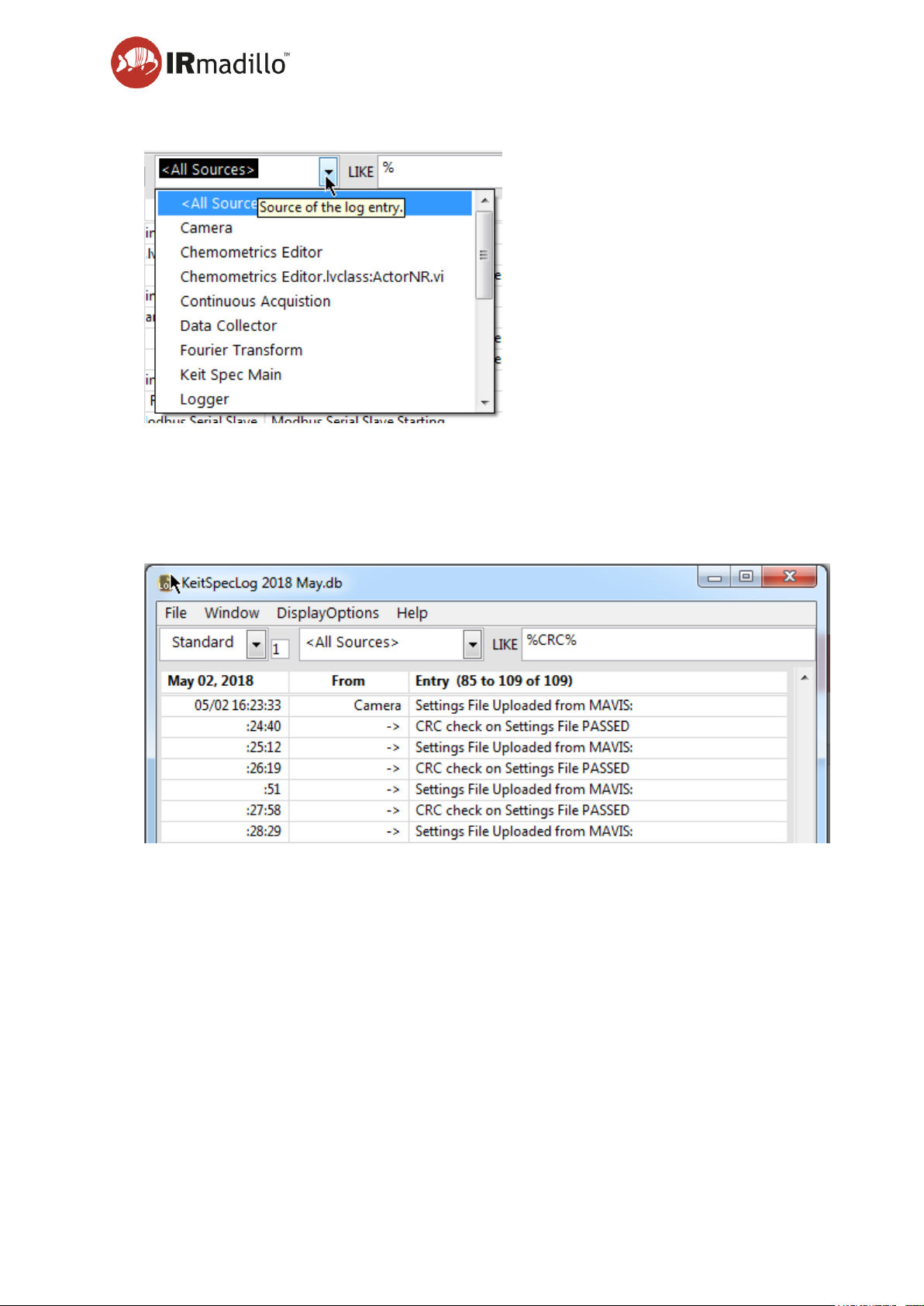
User manual Page 58
www.keit.co.uk Using the system and software: DOC0535 (10 July 2019, 16:56)
Back to Table of Contents
B. Filtering options
The log file can be filtered to limit the display the entries that you are interested in. Freetext search is achieved by entering it into the LIKE box. This search uses SQL syntax, so
the wildcard character is ‘%’.
This means that to search for ‘CRC’ anywhere in a log entry, you would enter ‘%CRC%’
into the LIKE box.
C. Log entries
Each log entry is displayed in a new row in the table. Hover the mouse pointer over long
fields to display information that overflows the space that you have available.
Page 59
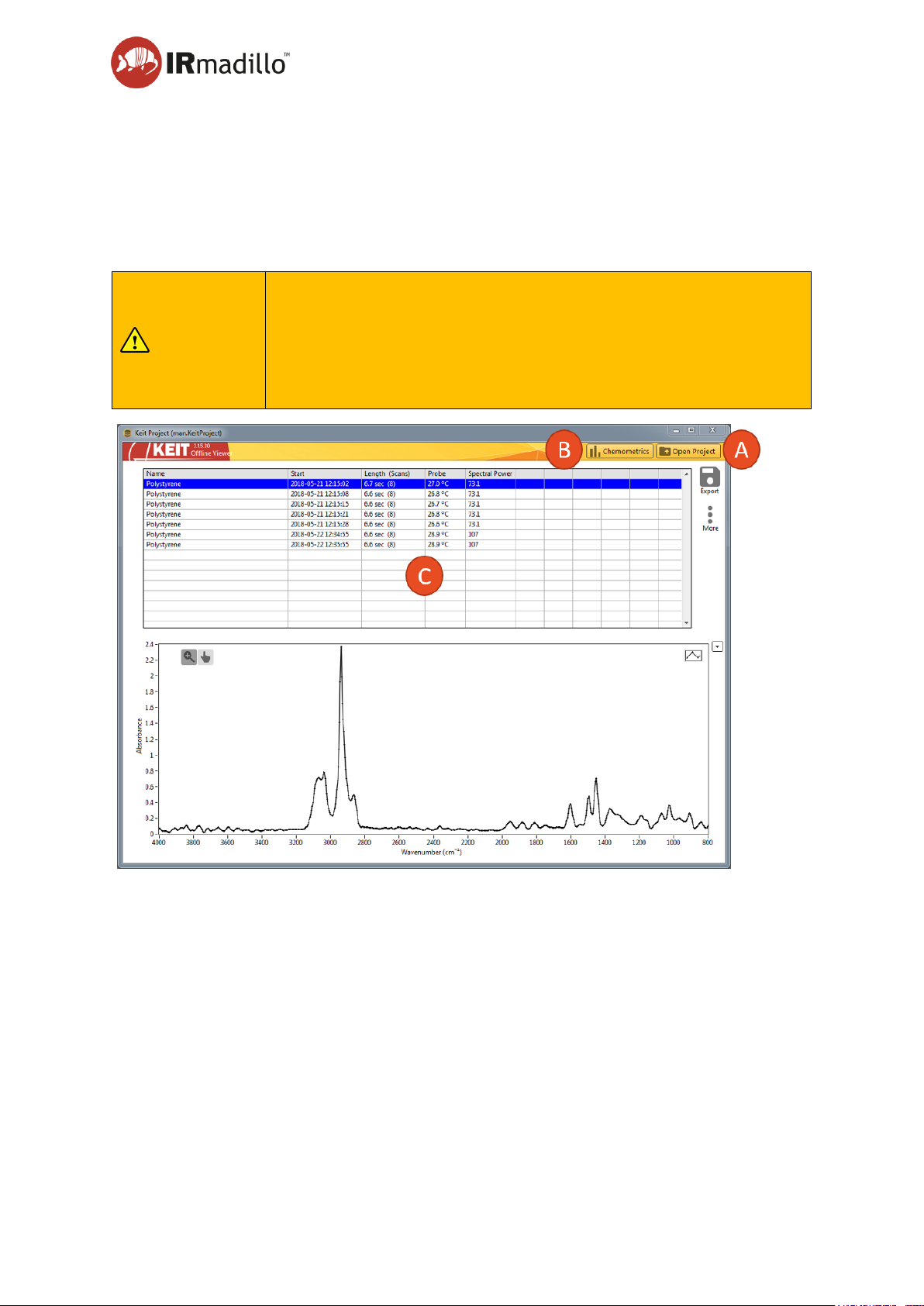
User manual Page 59
www.keit.co.uk Using the system and software: DOC0535 (10 July 2019, 16:56)
Back to Table of Contents
5.10 Offline viewer
Project files can be opened in the Keit Offline Viewer software. The software is installed
alongside the Keit Spec application on your computer. When the software opens, choose the
project file that you want to view. The interface that is displayed will depend on the type of
project that you open and appears very similar to the relevant tab (either Manual Sample
Acquisition or Batch Viewer) of the main application.
NOTE
If you wish to copy a project file to another location on your
computer, ensure that the project is not open within the Keit Spec
application since this may cause the data to be corrupted in the
copy. Keit recommends copying a project via the Save Copy of
Project option in Keit Spec. See Section 5.3 The Spectrometer
tab.
A. Open Project
Click this button to choose the project that you wish to open. The main panel (C) will
change depending on whether the project that you choose is a Manual or Continuous one.
B. Chemometrics
This button opens the Chemometrics configuration floating window for use with
Continuous Collection projects
C. Main Display Panel
This panel displays the information relative to the project. The panel will change to reflect
either the Continuous Collection Batch Viewer tab or the Manual Sample Acquisition tab.
Refer to the relevant section above for information about the controls within these panels.
Page 60

Page 60
www.keit.co.uk Data communication: DOC0535 (10 July 2019, 16:56)
Back to Table of Contents
6. Data communication integration and configuration
6.1 Modbus communications
The instrument can communicate over Modbus RTU or Modbus TCP/IP with a plant’s
distributed control system (DCS). Both of these Modbus interfaces are very similar, so the
Modbus RTU is described fully first before introducing Modbus TCP/IP.
6.1.1 Configure Keit controller
To enable either of the Modbus interfaces they must be enabled on the Configure Acquisition
tab. This example shows the Modbus Slave enabled for an RS-485 serial port.
This tab allows the communication to be set up, and communications to be debugged during
system programming.
Some third-party Modbus clients will throw an error or cause a COM port lock-up on the remote
computer if the spectrometer unexpectedly returns a null response to a command. This could
occur if the instrument is rebooting due to a watchdog reset event.
Page 61
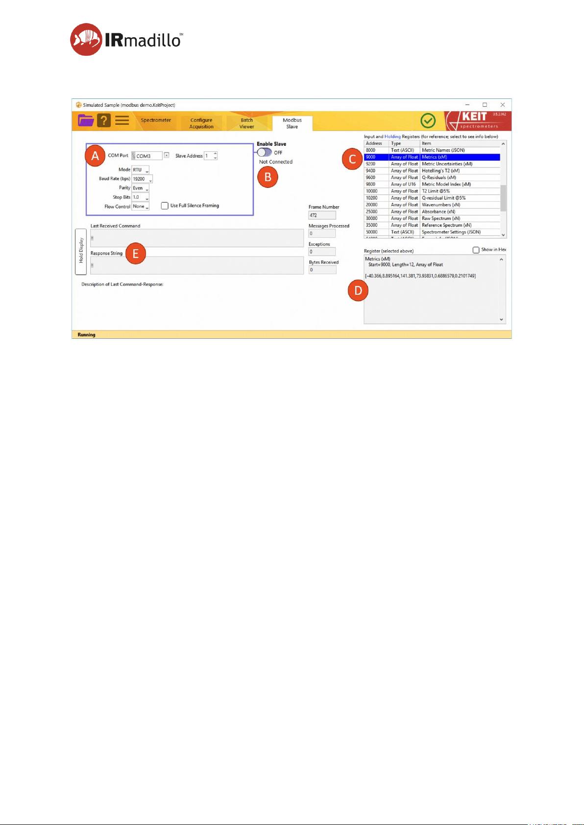
User manual Page 61
www.keit.co.uk Data communication: DOC0535 (10 July 2019, 16:56)
Back to Table of Contents
A. Communication Settings
Configure the communications port to match your plant control system settings.
B. Enable Slave
Once the settings are configured, enable the Modbus Slave to begin communicating with
the plant control system/Modbus master.
C. Register List
The Modbus registers that are available from the IRmadillo are shown in this panel, along
with their addresses. Clicking on a register will cause a description of its contents and its
data to be displayed in the box below (D). Note that:
Input registers are used to read data from the spectrometer.
Holding registers are used to write commands to the spectrometer.
For example, to read the output from chemometric models over Modbus you will need to
read data from these input registers:
1000 – Number of Metrics. Each metric is an output from the chemometric model.
9000 – Values for each Metric. In the screengrab the number of metrics is 6. Each metric
requires two 16-bit registers to represent a floating point number so the metrics array is
12 registers long.
D. Input Register Contents
The input register that is selected in the Register list (C) is summarised in this panel, along
with its contents. This display updates as the value in the register changes.
Page 62

User manual Page 62
www.keit.co.uk Data communication: DOC0535 (10 July 2019, 16:56)
Back to Table of Contents
E. Command Debug
The last Modbus command that was received, along with the response that the instrument
returned are shown in the boxes. Use the Hold Display button to freeze the display if the
values change too rapidly to read. The number of messages processed, and the errors
received are also shown to assist in debugging a connection to a plant control system.
6.1.2 Holding registers
It is possible to send commands from your Modbus master to the spectrometer. The
commands are shown in blue in the register list and described in detail in the register contents
below it. There are four accepted Spectrometer Actions associated with holding register 108,
Spectrometer Action. These are described in the table below.
Value
Name
Notes
1
Reenable Sagnac TEC
Resets the TEC (thermo-electric cooler) inside the
spectrometer. Note that it may take several hours
for the spectrometer to stabilise.
2
Reset Spectrometer
Performs a hard reset of the spectrometer. Note
that it may take several hours for the spectrometer
to stabilise.
3
Collect Background
Scan
Collects a new background scan.
4
Test Dialog
Pops up a dialogue box in Keit Spec. Can be used
to test the communication.
6.1.3 Representation of data in Modbus
Modbus uses different methods to represent data of different types. These are described in
the table below.
Data Type
Size (Registers)
Description
Float
2
IEEE 32-bit float in 2 Registers, Low Address=Most
Significant U16
Boolean
1
U16, False=0, True=1 (or higher)
U16
1
Unsigned 16 bit integer
U32
2
32-bit unsigned integer in 2 Registers, Low
Address=Most Significant U16
Array of
Float
2*N
N * IEEE 32-bit float in 2 Registers each
Page 63
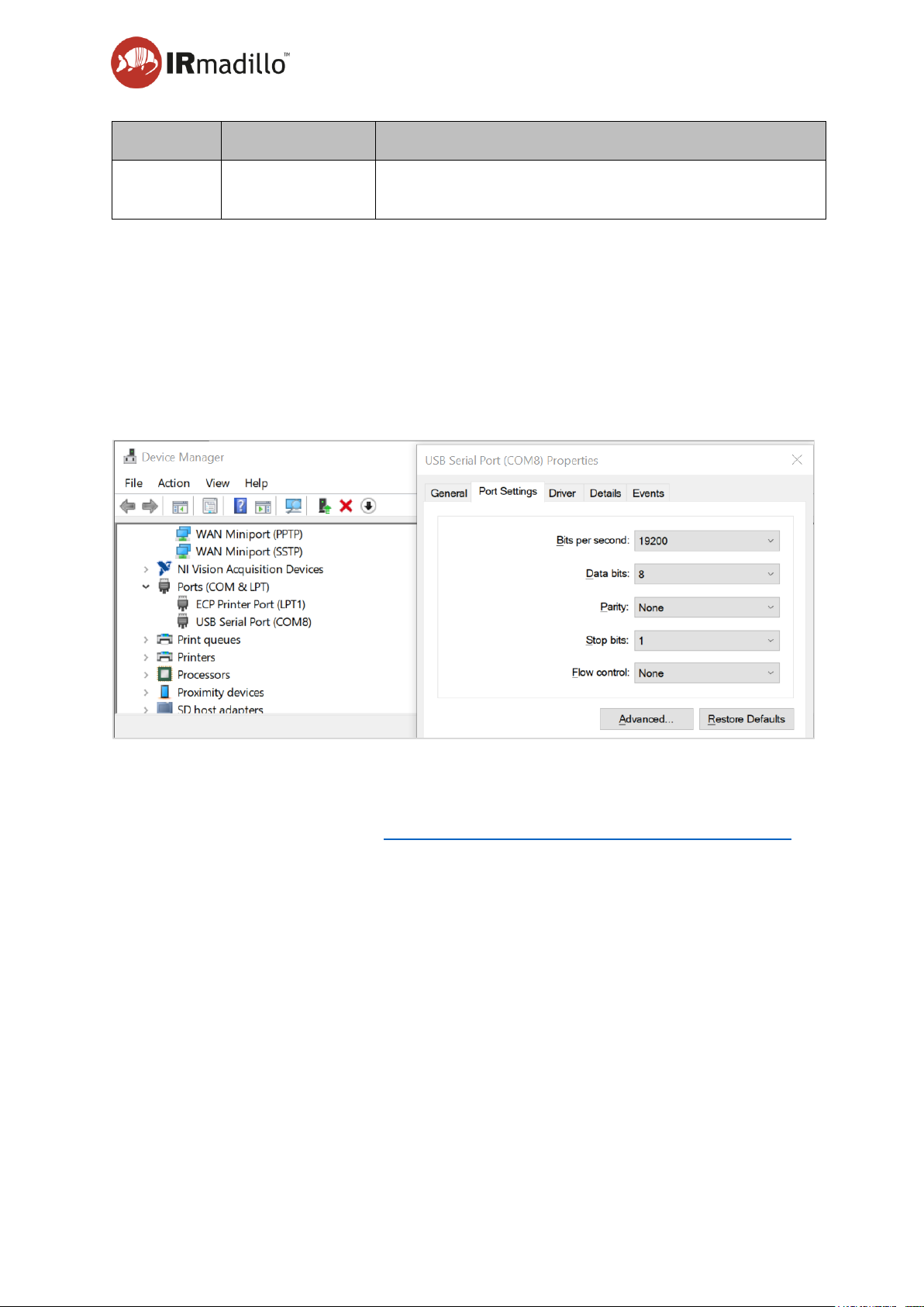
User manual Page 63
www.keit.co.uk Data communication: DOC0535 (10 July 2019, 16:56)
Back to Table of Contents
Data Type
Size (Registers)
Description
2D Array of
Float
2*N*M
N*M array, N sets of M numbers
6.1.4 Modbus RTU tutorial
Here is an example of getting data from the spectrometer using Modbus RTU. This should
provide a good feel for the practicalities involved.
First, you will need to setup a serial link to the controller from the master computer (e.g., your
desktop PC). Find the serial port’s COM number using device manager (in this example it is
COM8). Right click and set the port settings to match those in Keit Spec (Usually only the Bits
per second need changing).
You will need a piece of software that acts as a Modbus Master, examples are:
qmodmaster - https://sourceforge.net/projects/qmodmaster/
Radzio! Master Modbus Simulator - http://www.en.radzio.dxp.pl/modbus-master-simulator/
The example here uses Radzio. Once running, click on the Screwdriver/Spanner icon to open
the connection settings dialogue.
Page 64
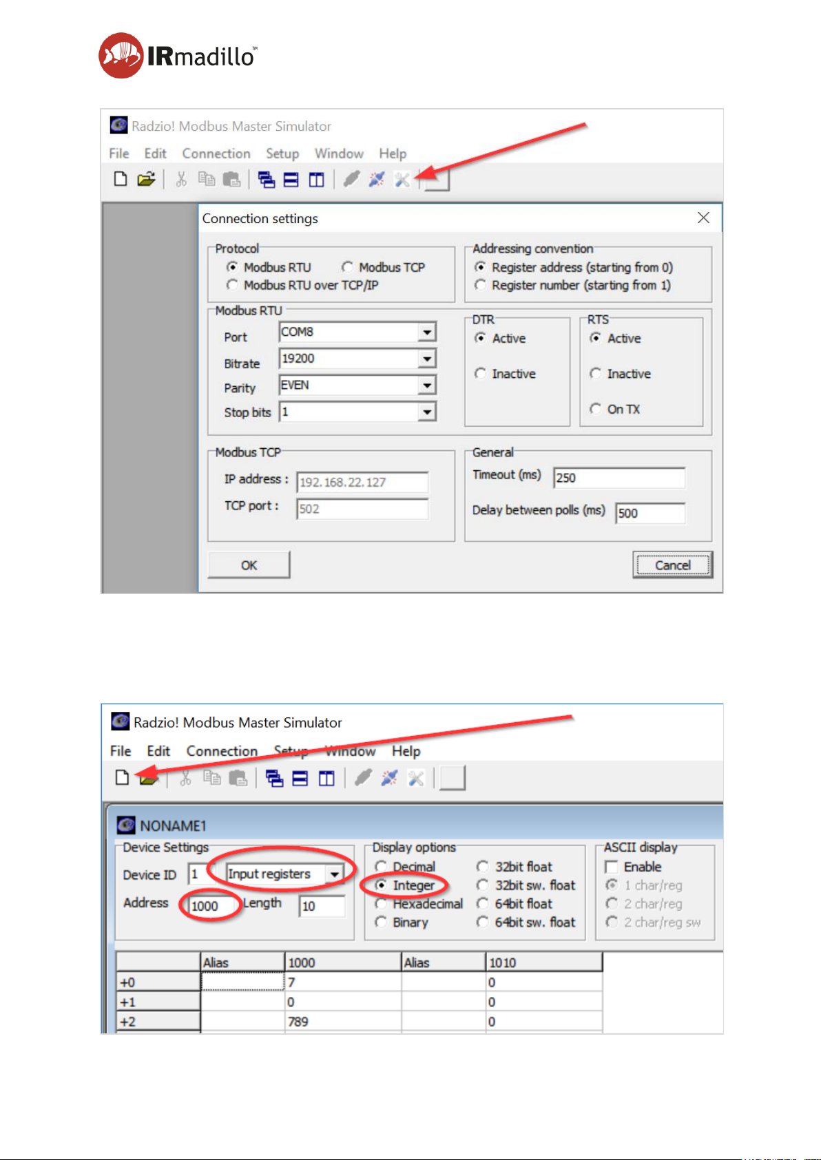
User manual Page 64
www.keit.co.uk Data communication: DOC0535 (10 July 2019, 16:56)
Back to Table of Contents
Select Protocol as “Modbus RTU” and the port number and bit rate to match that in the device
manager com port settings.
To start device communication, click on the new file icon, top left. This will open a window
with a list register addresses and their contents as shown below.
Page 65
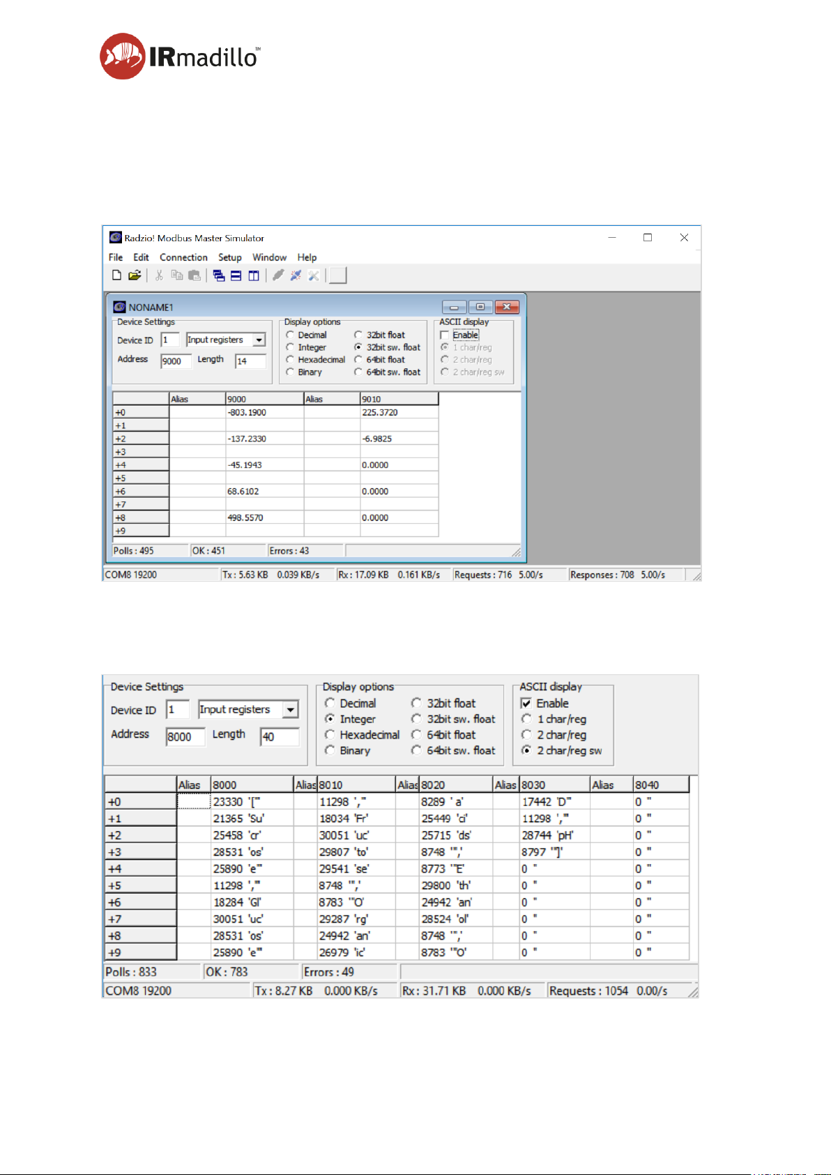
User manual Page 65
www.keit.co.uk Data communication: DOC0535 (10 July 2019, 16:56)
Back to Table of Contents
Here we are reading the number of metrics being output by the spectrometer. This is found
in register address 1000 which is an input register and the number type is Integer. In this case
there are 7 metrics.
To read the values of all 7 metrics we need to read 14 registers starting from address 9000.
These are decimals, not integers.
In the example above, the metric values are -803.19, -137.233, -45.1943…….-6.9825.
Similarly, the names of the metrics can be read from address 8000 and using the “[“ and “]”
delimiters to identify the start and end of the string array.
This gives: “Sucrose”, “Glucose”, “Fructose”, “Organic acids”, “Ethanol”, “OD” and “pH”.
Page 66
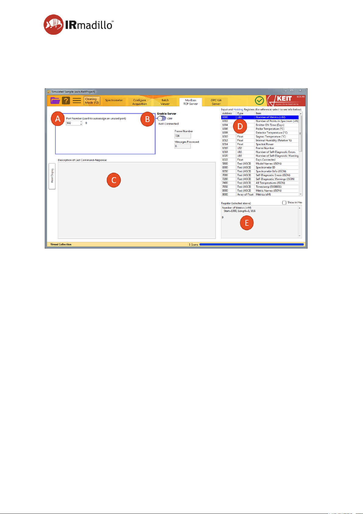
User manual Page 66
www.keit.co.uk Data communication: DOC0535 (10 July 2019, 16:56)
Back to Table of Contents
6.2 Modbus TCP server
The instrument can also communicate over Ethernet using Modbus TCP. To enable this
functionality turn on the Modbus TCP Server on the Configure Acquisition tab as described
earlier.
A. Communication settings
Configure the server’s port number as required to match your plant control system
settings.
B. Enable Server
Once the settings are configured, enable the Modbus Server to begin communicating with
the plant control system/Modbus client.
C. Command Debug
The last Modbus command that was received, along with the response that the instrument
returned are shown in the boxes. Use the Hold Display button to freeze the display if the
values change too rapidly to read. The number of messages processed, and the errors
received are also shown to assist in debugging a connection to a plant control system.
D. Register List
The available data outputs and register addresses are shown in the table. Select a register
to view its contents in the register box (E) below. The contents of the chemometric results
registers (registers 8000 – 20000) will depend on which chemometric analysis is being
performed.
E. Register View
Displays the contents of the register that is selected in the list above. Check the ‘Show in
Hex’ box to view the data in hexadecimal format.
Page 67
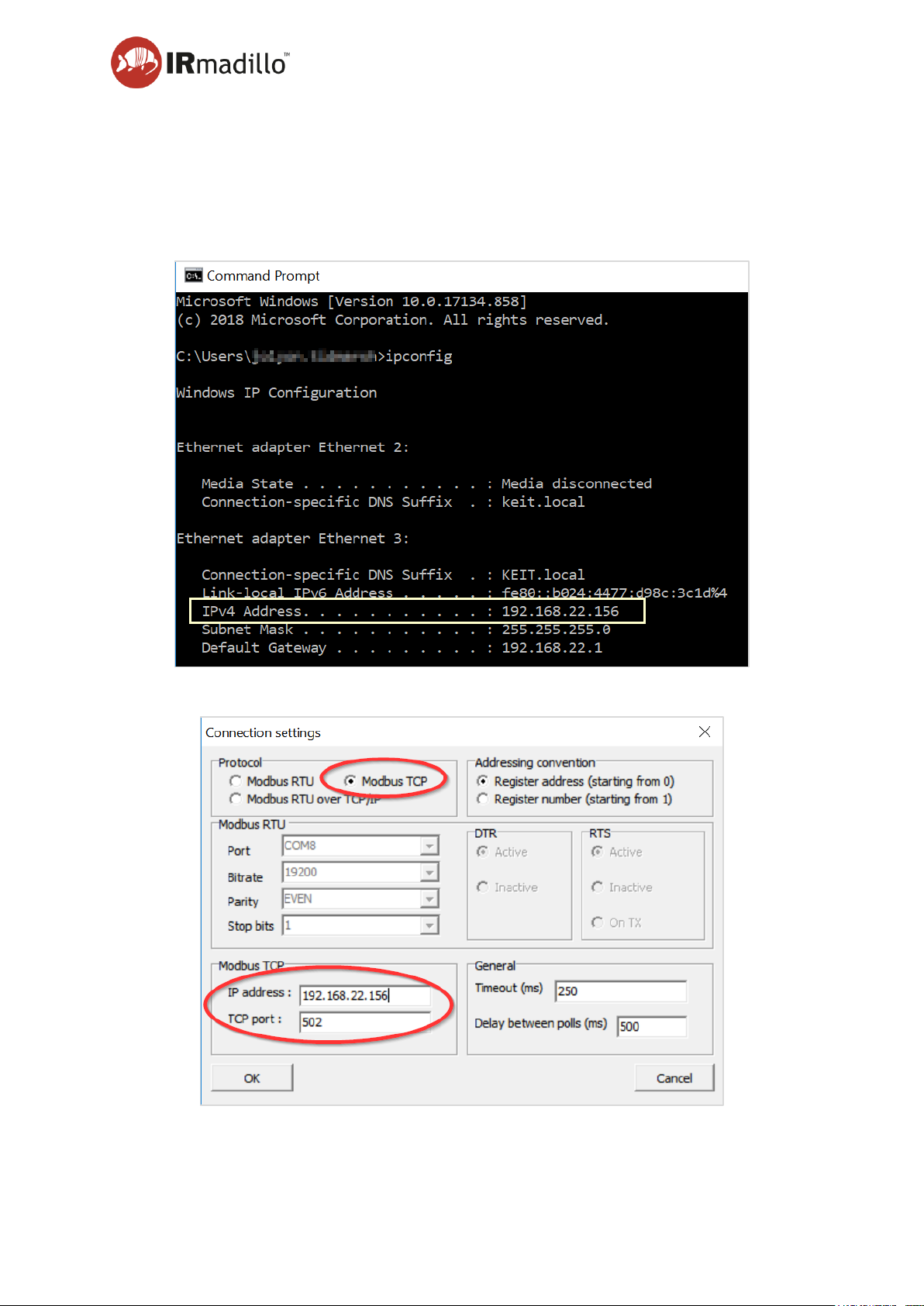
User manual Page 67
www.keit.co.uk Data communication: DOC0535 (10 July 2019, 16:56)
Back to Table of Contents
6.2.1 Getting started with Modbus TCP
The procedure is very similar to the Modbus RTU example given above. However, setting up
the connection is slightly different.
On the controller, open a windows CMD window and type ‘ipconfig’. This will provide you with
the IPv4 address:
The Radzio connection settings will then become:
Page 68
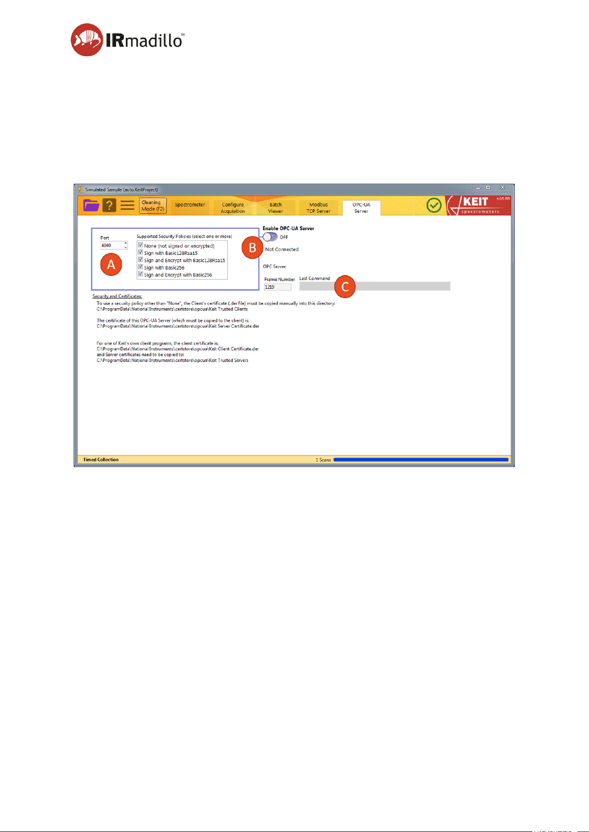
User manual Page 68
www.keit.co.uk Data communication: DOC0535 (10 July 2019, 16:56)
Back to Table of Contents
6.3 OPC-UA
The instrument can communicate over OPC-UA with a plant control system, subject to the
purchase of an additional software license for the OPC server. This tab allows the
communication to be set up and communications to be debugged.
OPC-UA requires an active connection to a local network that is shared with the computers or
control hardware that will consume the data that the IRmadillo generates.
A. Communication settings
Configure the communications port to match your plant control system settings.
B. Enable Slave
Once the settings are configured, enable the OPC-UA server to begin communicating with
the plant control system. The TCP/IP address of the OPC-UA server will be displayed to
aid debugging of the connection.
C. Command Debug
The last OPC command that was received is displayed in this box to assist in debugging
connection to the plant control system.
It is possible to send commands from your OPC client to the spectrometer. The accepted
commands are listed in the following table:
Page 69
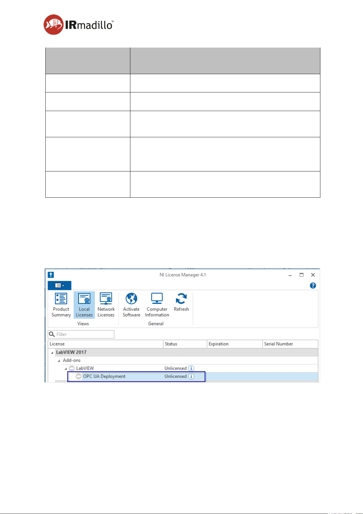
User manual Page 69
www.keit.co.uk Data communication: DOC0535 (10 July 2019, 16:56)
Back to Table of Contents
Instruction written to
“Command”
Description
Collect Background Scan
Collects a new background scan.
Zero Background Scan
Zeros the background, so the server is returning raw spectra.
Reset Spectrometer
Performs a hard reset of the spectrometer. Note that it may
take several hours for the spectrometer to stabilise.
Reenable Sagnac TEC
Resets the TEC (thermo-electric cooler) inside the
spectrometer. Note that it may take several hours for the
spectrometer to stabilise.
Test Dialog
Opens a dialogue box in Keit Spec. Can be used to test the
communication.
6.3.1 Licensing the OPC-UA server
The OPC-UA software component requires a licence for actual commercial use and should
be provided with one if it was specified.
If you need to install a license, then use “NI License Manager” (which is installed on your
controller PC) to activate “OPC UA Deployment” on the “Local Licenses” tab.
Click on the entry in the list, then click ‘Activate Software’ from the toolbar and follow the
prompts on screen to activate the license.
Once the license is activated, turn on the “Enable OPC-UA server” switch on the OPC-UA
Server tab in the Keit Spec software. When the OPC-UA server is active, it will be visible on
the local network that the IRmadillo control computer is connected to.
Third-party OPC-UA clients such as UAExpert (freely downloadable from United Automation)
may be used to connect to the OPC-UA server and interrogate its data.
Page 70
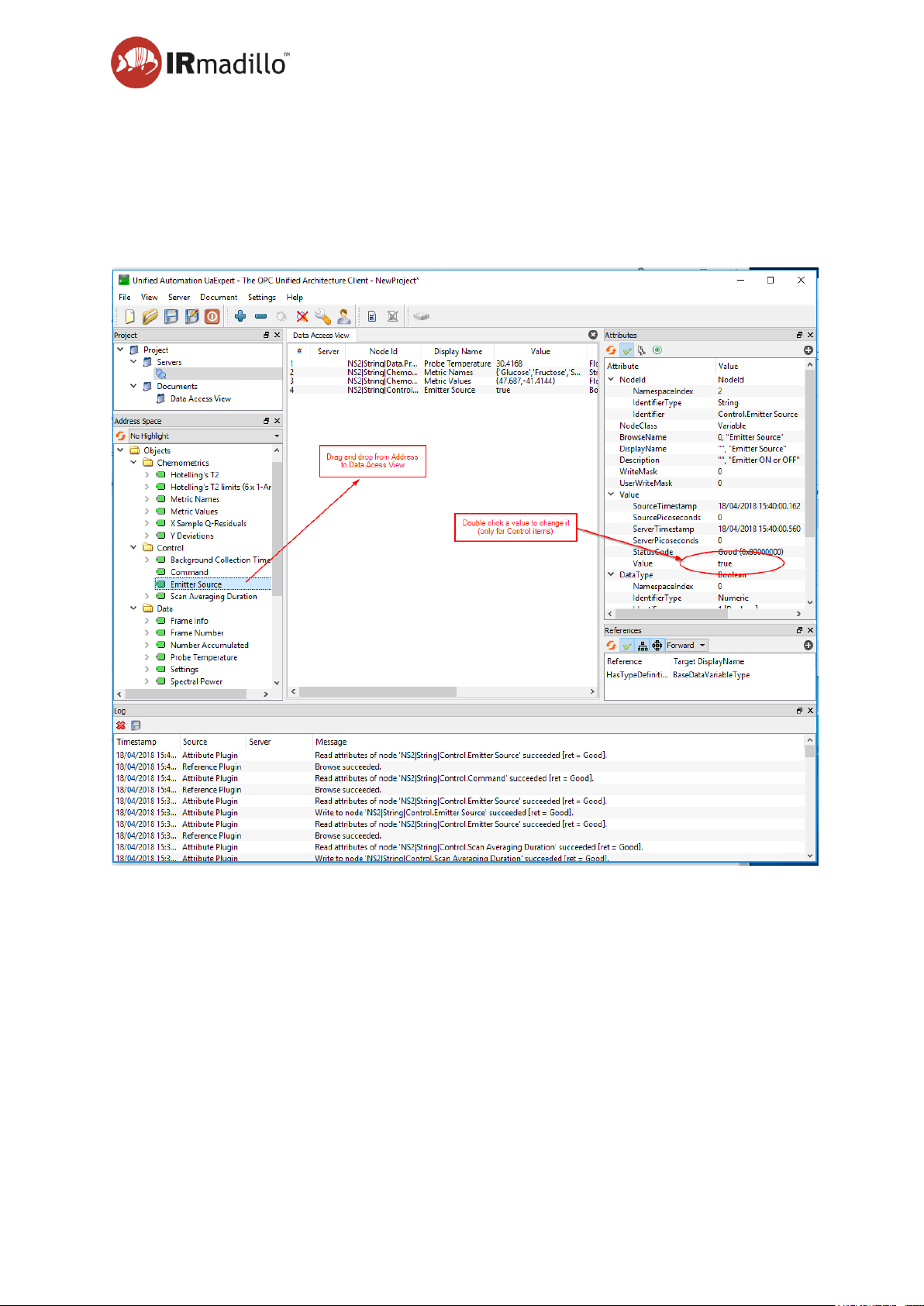
User manual Page 70
www.keit.co.uk Data communication: DOC0535 (10 July 2019, 16:56)
Back to Table of Contents
6.3.2 UaExpert client
UaExpert is a general OPC-UA client that can connect to the server and shows the full
“address space” of data items being served. See Illustration below. This can be used to
experiment with changing the “Control” items, which are used to command “Keit Production
OPC”. For example, changing the Value of “Control.Command” to “Collect Baseline” will cause
a new baseline to be collected.
Figure 3: UaExpert general-purpose OPC-UA client. Use "Server>Add..." to configure a connection to the
URL of "Keit Production OPC"
6.3.3 OPC address space
OPC-UA servers publish a tree of information relevant to their function. In the case of the
IRmadillo, the tree contains spectral information, output from the chemometric models that
have been loaded, and control and performance information about the spectrometer
operation.
Page 71
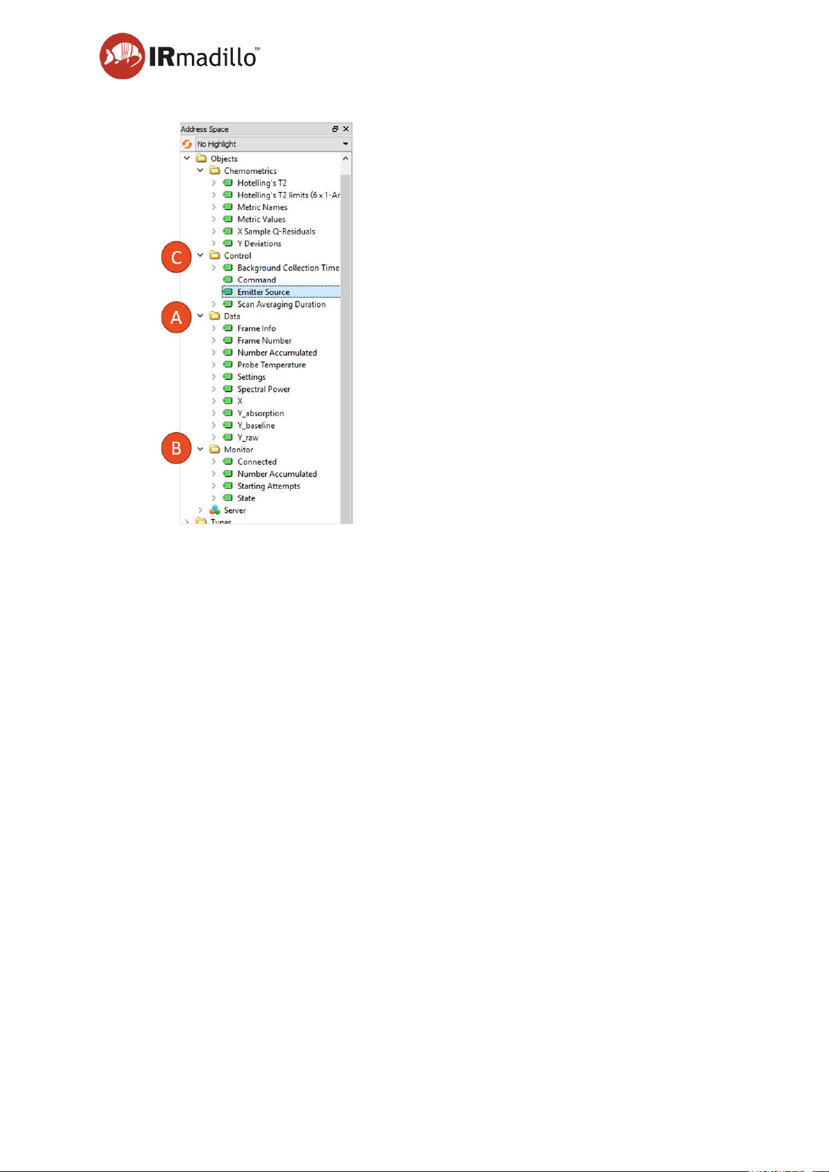
User manual Page 71
www.keit.co.uk Data communication: DOC0535 (10 July 2019, 16:56)
Back to Table of Contents
A. Data node
The “Data” OPC node contains Variables that describe the latest spectral measurement.
Not all of them change with each new measurement, and “Settings” should never change.
Please note that OPC-UA items have an attached “Description” that can be used to
describe them. For example, “Y_baseline” has the description “Reference spectrum that
defines zero absorption.” Descriptions of most of these Variables will thus be made via
OPC, rather than in this document.
B. Monitor node
This node is for informational items that are not part of a spectral measurement. The
current only Variable is “Number Accumulated” which is a running count of “frames” being
accumulated in the next average. This is useful to show the spectrometer is collecting
when it is running a long average (frames tend to be about 1 per second, but an average
might be many minutes). Other monitor variables may be added.
C. Control node
These are Variables that the Client(s) may set in order to control the server.
“Averaging” is the number of “frames” that are combined in a single spectrum.
“Command” is a line of text that is a means of communicating. For technical reasons, this
is a two-way communication channel. The server will generally reply to an instruction by
setting “Command” to the same instruction preceded by “-->”. The server will also write
status messages to “Command”; these always start with “-->”.
Page 72

User manual Page 72
www.keit.co.uk Data communication: DOC0535 (10 July 2019, 16:56)
Back to Table of Contents
Instruction written to “Command”
Description
Collect Background Scan
Causes the spectrometer to collect a new
Reference (baseline) spectrum.
Zero Background Scan
Zeros the baseline, so the server is returning
raw spectra.
Reset Spectrometer
Performs a hardware reset.
Reenable Sagnac TEC
Reenables Sagnac TEC.
Test Dialog
Opens a dialog in the detector component, just
to demonstrate communication.
Page 73

User manual Page 73
www.keit.co.uk Data communication: DOC0535 (10 July 2019, 16:56)
Back to Table of Contents
6.4 Controller administrator guidance
When connecting Keit’s controller to communicate to your distributed control system (DCS)
using Ethernet, you will need to connect it to your local area network (LAN). Some changes
may be required to ensure compliance with your internal Information Technology (IT) policies.
Changes to the controller may cause the spectrometer to become unreliable. The information
below should help to avoid problems.
Item
Guidance
User account to run
spectrometer
A domain or local user account may be used. Keit Spec does
not support simultaneous running by two different users.
The controller incorporates an auto-restart feature. To take
advantage of this, the user account must be set to
automatically log in and run the Keit Spec software.
Keit recommends always using the same user account to run
the spectrometer.
Administrator account
Do not use the administrator account for running the
spectrometer. It should only be used to configure the
controller.
A domain or local user account may be used.
Virus Scanning software
When installing an anti-virus solution, please ensure it does
not disrupt the spectrometer by consuming too much CPU
when scanning.
Windows updates
Windows updates are known to cause spectrometer outages
and are set to be manual by default so that they can be
installed during planned maintenance.
BIOS password
You may need to set a BIOS password.
Page 74
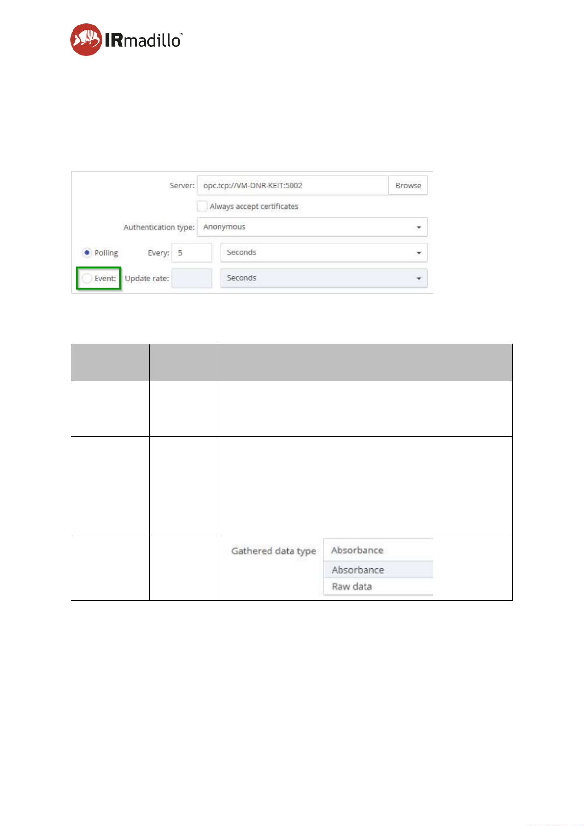
User manual Page 74
www.keit.co.uk Data communication: DOC0535 (10 July 2019, 16:56)
Back to Table of Contents
6.5 Connecting the spectrometer to Camo Analytics’ Process Pulse
The connection from Process Pulse is based on an OPC-UA connection and requires the OPC
Server to be running on the spectrometer’s control unit.
In Process Pulse, define the data source by browsing for the desired OPC Sever.
Then select the following settings:
Item
Preferred
setting
Guidance
Authentication
type
Anonymous
Alternatively, you may enter the appropriate authentication
credentials for your system.
Event
Event triggering is preferred to polling.
When using polling mode Process Pulse requests data at a
given frequency. Data is then read regardless of whether or
not the values have changed since the previous reading.
In event mode, Process Pulse reads data and imports only
if the values have changed.
Gathered
Data Type
Absorbance
Once data type is chosen, the user has the possibility to manage tag names.
Page 75
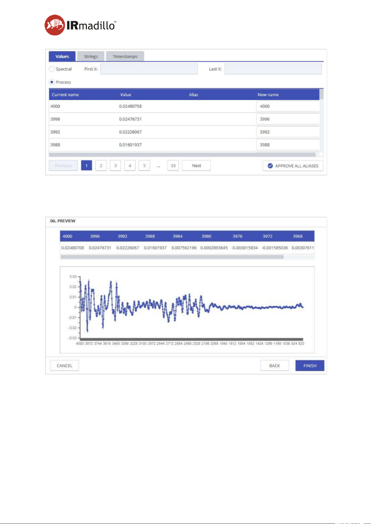
User manual Page 75
www.keit.co.uk Data communication: DOC0535 (10 July 2019, 16:56)
Back to Table of Contents
After that, different triggering options can be defined.
Finally, a preview of the data to be collected is shown so that a final validation of the settings
can be done before completing the data source setup.
Page 76

Page 76
www.keit.co.uk Maintenance: DOC0535(10 July 2019, 16:56)
Back to Table of Contents
7. Maintenance
There are no user-serviceable parts inside. Please contact Keit or our local agent to arrange
service or repair. Service should only be performed by suitably trained engineers.
7.1 Service and support contacts
Website: www.keit.co.uk
Postal address: Keit Ltd.
Unit 4, Zephyr Building
Eighth Street, Harwell Campus
Didcot
Oxfordshire
OX11 0RL
United Kingdom
7.2 Preventative maintenance and service intervals
It is recommended that a Keit engineer performs an annual service to carry out preventative
maintenance and recalibration. The work performed will depend on your configuration and
installation requirements.
Please contact Keit directly to arrange a service visit.
7.3 Protecting and cleaning the dip probe ATR element
The ATR element is made of a fragile infrared glass and may scratch or chip if mistreated.
Cleanliness of the ATR is essential to good performance and cleaning should be carried out
regularly, frequency depending on your application (if you are unsure of a suitable frequency,
please contact Keit who can assist you in deciding on best practice).
You may wish to switch the software into cleaning mode to aid with cleaning. This is outlined
in Section 5.3 The Spectrometer tab.
Page 77

User manual Page 77
www.keit.co.uk Maintenance: DOC0535 (10 July 2019, 16:56)
Back to Table of Contents
7.3.1 Cleaning instructions: infrared glass probes
Cleaning instructions for IRmadillo fitted with INFRARED GLASS probe (IRmadillo25 and
IRmadilloHot):
• Carefully retract the system from the vessel or pipe taking care not to chip or scratch
the ATR.
• Rinse the ATR element with a suitable solvent. The choice of solvent will depend on
your process. The following are suitable:
• Water
• Acetone
• Alcohols
• Surfactant solutions (not alkali)
• Alkanes (hexane, cyclohexane, etc.)
• Ethers
• You may fully immerse the ATR in solvent if needed.
• Carefully wipe the ATR with a lint-free cloth (Keit recommends using Webril Handi-
Pads [available from ThorLabs item number CP-100] and Solon Cotton Tipped Swabs
[available from Edmund Optics item number 56-926]). It is important to use lint-free
wipes to avoid the risk of damage to the glass.
• The metal tube of the probe can also be cleaned by wiping with a cloth.
• For hard to remove fouling (such as biofilms or dried on chemicals) Keit recommends
an oxidative acid clean. To perform this:
o First clean the ATR using the methods outline above
o Place the PTFE sample cell on the end of the probe and fill with 1 M nitric acid
solution
o Leave to soak for 1 hr
o Carefully remove the acid using a pipette and fill the sample cell with water
o Remove the water using a pipette
o Remove the sample cell and rinse the ATR again with water
o Carefully wipe the ATR with a lint-free cloth (Keit recommends using Webril
Handi-Pads [available from ThorLabs item number CP-100] and Solon Cotton
Tipped Swabs [available from Edmund Optics item number 56-926]). It is
important to use lint-free wipes to avoid risk of damage to the glass.
• It may be necessary to repeat the cleaning steps again if the contaminant has only
been partially removed.
CAUTION
Under no circumstances should you attempt to clean the ATR
with abrasive materials (such as a scouring pad), or alkaline
materials (such as hydroxides). These will damage the ATR
element and will invalidate the warranty.
Page 78
User manual Page 78
www.keit.co.uk Maintenance: DOC0535 (10 July 2019, 16:56)
Back to Table of Contents
7.3.2 Cleaning instructions: diamond probes
Cleaning instructions for IRmadillo fitted with DIAMOND probes (IRmadilloDiamond) only:
• Retract the system from the vessel or pipe
• Rinse the ATR element with a suitable solvent. The choice of solvent will depend on
your process. The following are suitable:
• Water
• Acetone
• Alcohols
• Surfactant solutions
• Alkanes (hexane, cyclohexane etc…)
• Ethers
• You may fully immerse the ATR in solvent if needed.
• Carefully wipe the ATR with a cloth
• The metal tube of the probe can also be cleaned by wiping with a cloth.
• For hard to remove fouling (such as biofilms or dried on chemicals) Keit recommends
an oxidative acid clean. To perform this:
o First clean the ATR using the methods outline above
o Place the PTFE sample cell on the end of the probe and fill with 1 M nitric acid
solution
o Leave to soak for 1 hr
o Carefully remove the acid using a pipette and fill the sample cell with water
o Remove the water using a pipette
o Remove the sample cell and rinse the ATR again with water
o Carefully wipe the ATR with a cloth
• It may be necessary to repeat the cleaning steps again if the contaminant has only
been partially removed.
CAUTION
The alkali soak may only be used with instruments fitted with
the DIAMOND probe. Alkalis will damage the ATR elements of
any probes fitted with INFRARED GLASS. Soaking
instruments with infrared glass probes in alkali will invalidate
their warranties. If you are unsure which type of instrument
you have, contact Keit.
• In some cases it may be necessary to perform an alkali clean on the diamond probe:
o First clean the ATR using the methods outline above
o Place the PTFE sample cell on the end of the probe and fill with 1 M sodium
hydroxide solution
o Leave to soak for 1 hr
o Carefully remove the alkali using a pipette and fill the sample cell with water
o Remove the water using a pipette
o Remove the sample cell and rinse the ATR again with water
o Carefully wipe the ATR with a cloth
• It may be necessary to repeat the cleaning steps again if the contaminant has only
been partially removed.
Page 79
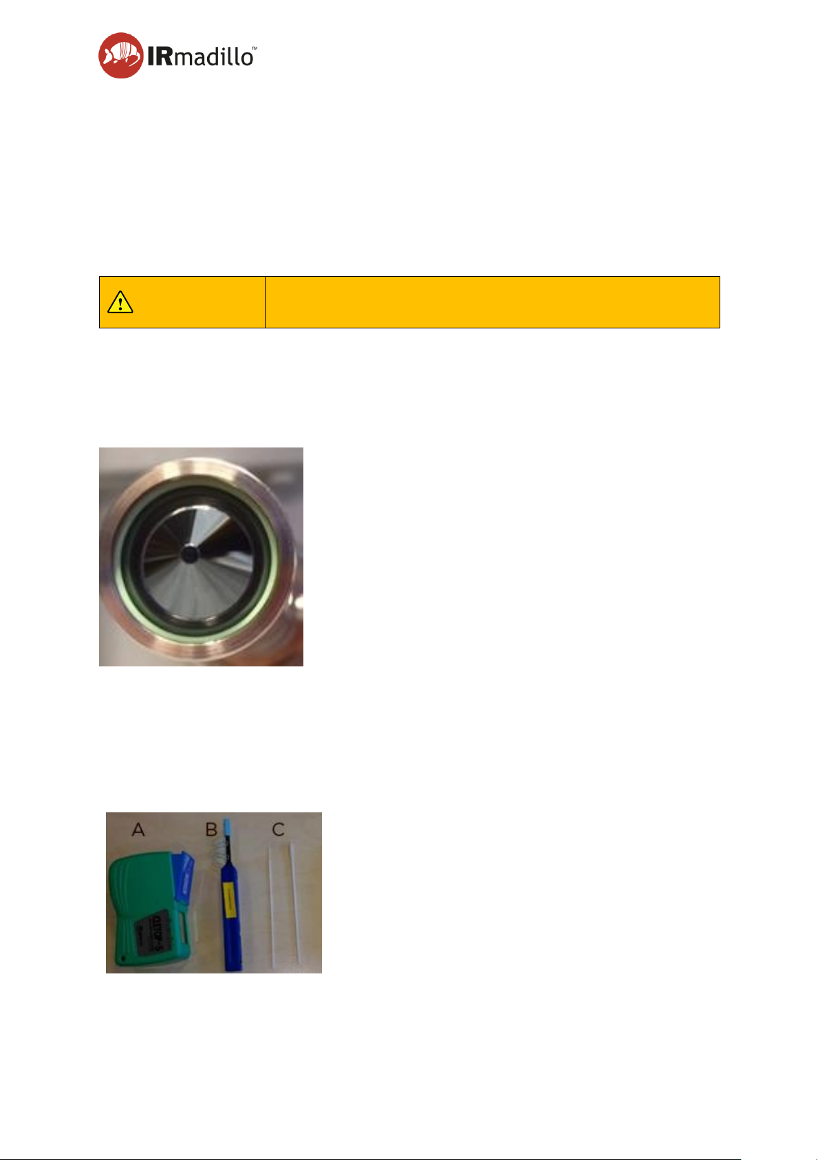
User manual Page 79
www.keit.co.uk Maintenance: DOC0535 (10 July 2019, 16:56)
Back to Table of Contents
7.4 Cleaning prior to Sterilise-in-Place (SIP)
SIP is outside the scope of the Ex-certificate of this product. Do not exceed the analyte
temperature ratings specified on the product label. If you perform a SIP (sterilise in place) step
as part of your process, it is important that you clean the probe using the steps outline above
before performing SIP. This is especially important if you perform a dry SIP process. Contact
Keit for advice before subjecting your probe to an SIP process.
CAUTION:
Failure to clean the probe before SIP may result in permanent
damage to the ATR element and will invalidate the warranty.
7.5 ATR and O-ring
The O-ring must be correctly seated and in good condition with no cracks, bulges or visible
deterioration. An example of this is shown in the photo below.
7.6 Cleaning the fibre optic data cable connectors
Once installed and in normal operation there should be no need to clean the fibre optic
connectors. If the instrument needs to be moved so the connectors have to be disconnected,
it is recommended that the connectors are cleaned before being connected.
Cleaning kits are available from Keit. The kit includes:
A. A fibre cleaner for male connectors
B. A fibre cleaning pen for female connectors
C. Swabs (Q-tips) 1.25 mm and 6 mm head width.
Page 80
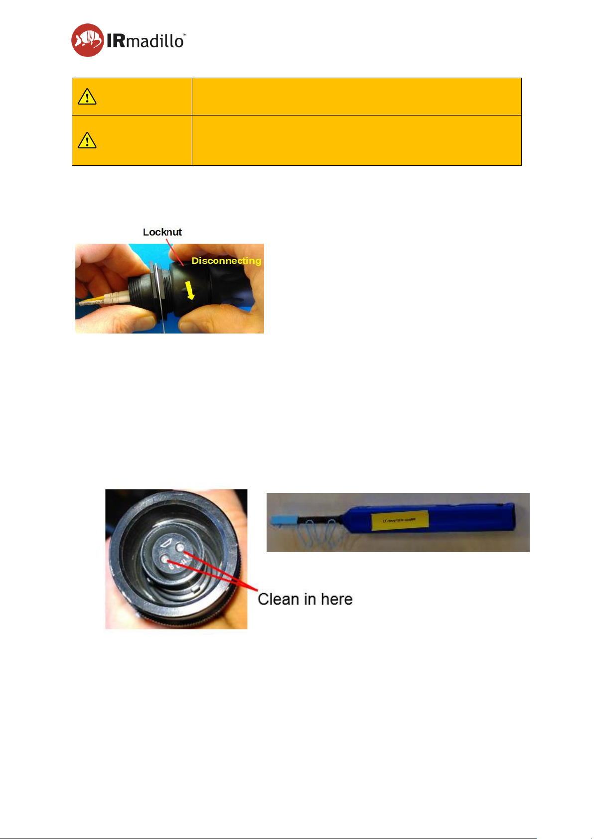
User manual Page 80
www.keit.co.uk Maintenance: DOC0535 (10 July 2019, 16:56)
Back to Table of Contents
NOTE:
Keep the dust caps on connectors and fibres when not in use.
Never leave an exposed fibre connector.
NOTE:
Protect the fibre from stress and tight bends (< 30mm bend
radius not allowed!). Tight bends cause a stress at the glass
surface and increase the probability of fracture.
Step 1. To disconnect the connector from the back of the control unit, turn the locknut as
shown below. Don’t force it. Forcibly turning any other part of the assembly may break
the connector.
Step 2. Using the cleaning pen, clean the female ports on the back of the instrument end of
the fibre data communication cable by pressing the pen into the fibre receptacles until
it clicks.
Step 3. Disconnect the fibre cable from the spectrometer by undoing the grub screw and
unscrewing the connector.
Step 4. Place the tip of the pen into one of the ports on the connecter and then press the pen
outer shell towards the connecter. You will hear a “click” when the process is
complete. Repeat this for the other port on the connecter.
Page 81
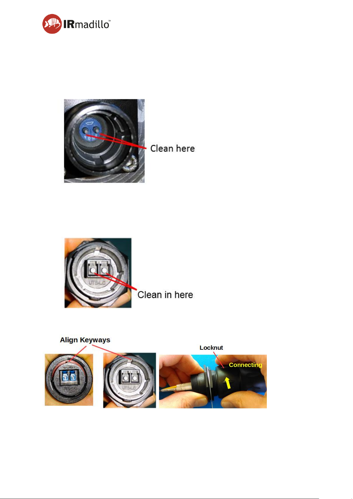
User manual Page 81
www.keit.co.uk Maintenance: DOC0535 (10 July 2019, 16:56)
Back to Table of Contents
Step 5. Next, clean the male connector on the back of the spectrometer. Take a Q-tip or
cotton bud and apply a small amount of isopropanol or methanol to the tip. Shake to
remove excess solvent and allow to dry for ~ 10 s. Use the tip of the swab to clean
one of the ports, then discard the Q-tip.. Repeat the process with a new Q-tip on the
other port.
Step 6. Finally, clean the connector at the controller. Take a Q-tip or cotton bud and apply a
small amount of isopropanol or methanol to the tip. Shake to remove excess solvent
and allow to dry for ~ 10 s. Use the tip of the swab to clean one of the ports, then
discard the Q-tip. Repeat the process with a new Q-tip on the other port.
Step 7. Reconnect the connectors. Align the keyways and turn the locknut as shown until a
distinct click is heard.
Page 82

User manual Page 82
www.keit.co.uk Maintenance: DOC0535 (10 July 2019, 16:56)
Back to Table of Contents
7.7 Troubleshooting
If you encounter any issues either during installation or during use of the IRmadillo please
contact Keit ([email protected]).
Issue
Cause
Potential Solution
Software cannot connect
to spectrometer
No power to spectrometer
Check mains power
connection
Fibre-optic link issue
Check integrity of the fibreoptic link, remake the fibreoptic connections or clean
the fibre-optic connectors
Modbus communications
appear unresponsive
despite the spectrometer
running normally
Some third-party Modbus
clients can crash the USB
subsystem on the client PC,
causing a loss of connection
Restart the USB COM port
on the remote computer.
The Modbus client should
be designed to recover from
a null response, and have a
finite timeout period.
Insensitive to analyte
changes
Dust cap still in place
Remove dust cap from ATR
element
ATR element not in sample
Ensure ATR element is
properly immersed in
sample to be analysed
Noise in spectra that
doesn’t disappear with
longer sampling times
Background scan taken with
insufficient averaging
Experiment with increased
background scan acquisition
time
Negative peaks in
spectrum
Background scan taken with
a dirty probe
Clean ATR element and
take a new background
scan.
Signal too noisy
Insufficient averaging
Experiment with increased
averaging
Page 83

User manual Page 83
www.keit.co.uk Maintenance: DOC0535 (10 July 2019, 16:56)
Back to Table of Contents
Issue
Cause
Potential Solution
Low / No signal
Instrument warming up
Allow the instrument to
warm up for several minutes
before checking raw
spectrum. Recommended to
allow 12 hr to fully warm up
before use.
Switch on from a very low or
a high temperature
Allow to warm up for 12 hr
before checking raw
spectrum. It will take time to
stabilise the internal
temperature and you must
wait for this to occur.
Thermal shutdown activated
operation outside of
specification.
Contact Keit for advice on
resetting the instrument
Appearance of
unexplained features
(characteristically seen at
1600 – 1700 cm-1)
Water vapour present in
instrument
Check that your purge gas
specification is suitable and
that your gas supply is free
flowing with no blockages
Unrepeatable
measurements
Damage to ATR element
Contact Keit
Contamination of ATR
element
See Section 7.3 Protecting
and cleaning the dip probe
ATR element.
Dip probe misaligned by
inappropriate use
Contact Keit
Analyte temperature
changes
Some cross sensitivity is
expected
7.8 Remote Health Check
Keit can perform an examination of your system’s health data to determine whether any
servicing needs to be carried out. There are two options for carrying out the health check:
7.8.1 Remote access
If your control PC is connected to the Internet and you are willing to allow remote access, then
this is the easiest way to arrange a health check.
Step 1. Run TeamViewer on the control PC.
Step 2. Send Your ID and Password to [email protected] and request a remote health
check. Ensure that the system remains switched on and connected to the Internet
Page 84
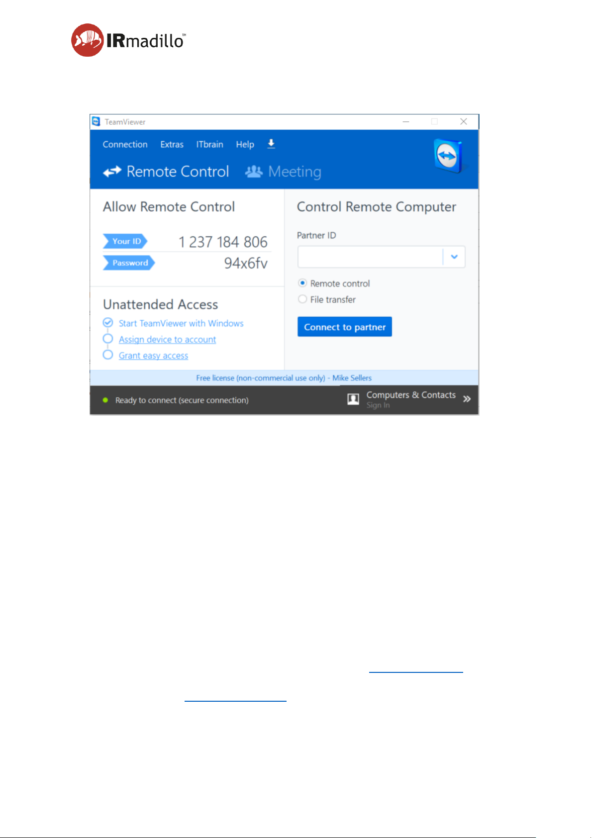
User manual Page 84
www.keit.co.uk Maintenance: DOC0535 (10 July 2019, 16:56)
Back to Table of Contents
until you are notified that the health check has been completed. If this is
inconvenient, please contact Keit to arrange a specific time for the health check.
7.8.2 Sending data manually
If you would prefer not to allow remote access, then please send Keit the health check data
directly.
Step 1. Determine how many user accounts have been used on the control PC (the
system’s health data is stored in each user’s My Documents folder on the PC).
Step 2. Locate the Keit Spec data folder, which can be found at:
C:\Users\[user_name]\Documents\LabVIEW Data\KeitSpec
where [user_name] is the user account that has been used to log into the control
PC.
Step 3. Open the folder:
C:\Users\[user_name]\Documents\LabVIEW Data\KeitSpec\Background History
Step 4. Check that the latest Background, yyyy-mm-dd xxxxxx.KeitDataZip, shows today’s
date. If it does not, Keit recommends taking a new background.
a health check. The Keit Spec folder is likely to be large; Keit recommends using
WeTransfer (www.wetransfer.com), which is a free service and does not require an
account.
Step 6. Repeat steps 2-5 for every user account that has been used to run the spectrometer.
Page 85
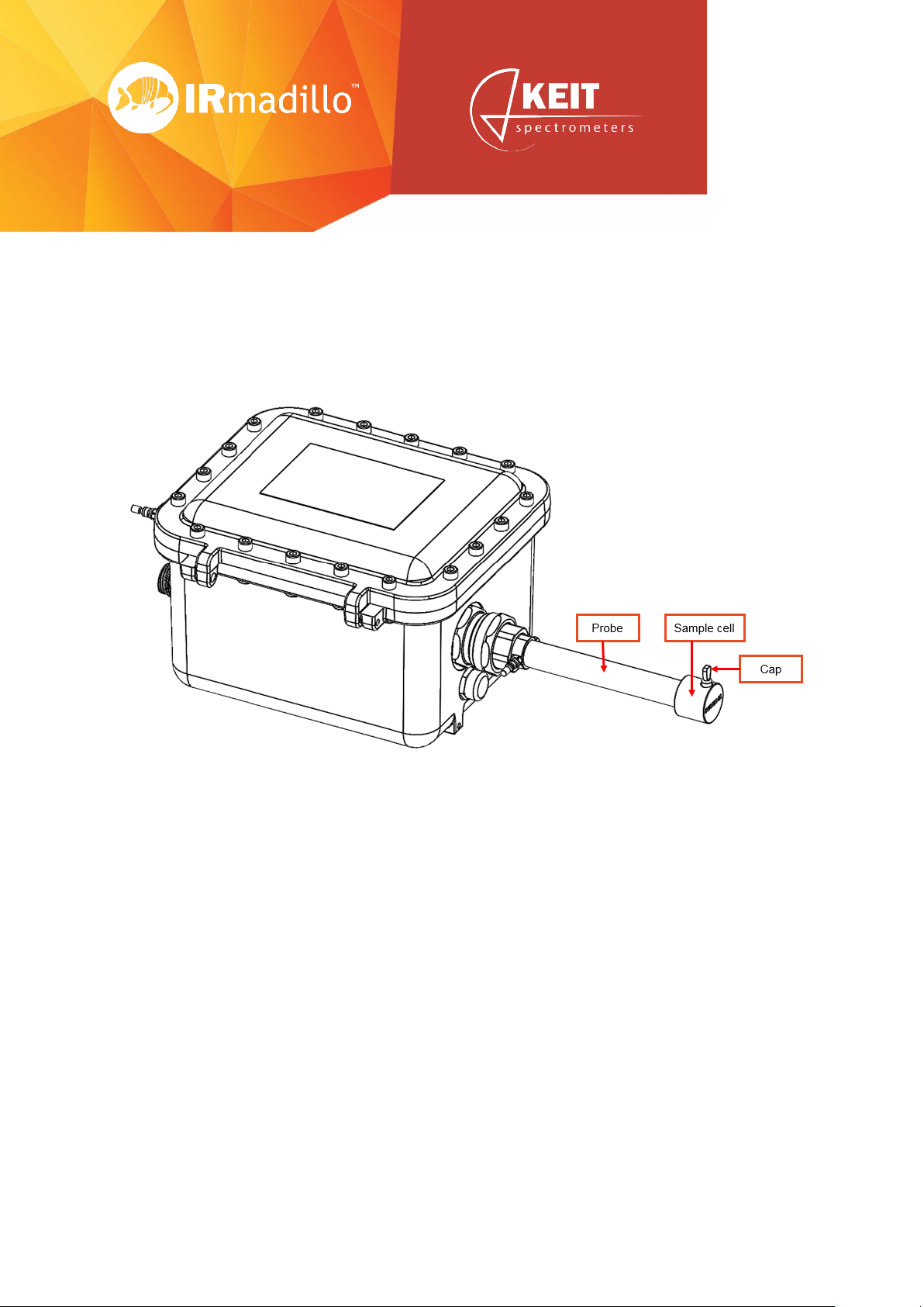
Page 85
www.keit.co.uk Accessories: DOC0535 (10 July 2019, 16:56)
Back to Table of Contents
8. Accessories
8.1 Sample cell
Ensure the sample cell is clean and dry before use. Visually inspect the O-ring, and replace if
worn, swollen or damaged.
Place the sample cell over the end of the probe and gently but firmly push it onto the probe
(you may find it easier if you slightly twist the sample cell as you do so). The sample cell is
properly installed when it cannot move any further onto the probe (you may hear a “click” as
the end of the probe touches the cell – this is perfectly normal).
Fill the sample cell using a pipette (or similar), ensuring the ATR element is completely
covered by the sample. The chamber has a volume of ~5ml (If you are using a volatile solvent
it is recommended to fit the cap onto the fill port).
After collecting your spectra, empty the sample cell using a plastic Pasteur pipette. Remove
as much of the sample as possible before removing the cell from the probe end. Once the
sample cell is empty, pull it off of the probe, and thoroughly clean and dry both the ATR
element and the sample cell before repeating any measurements.
Page 86
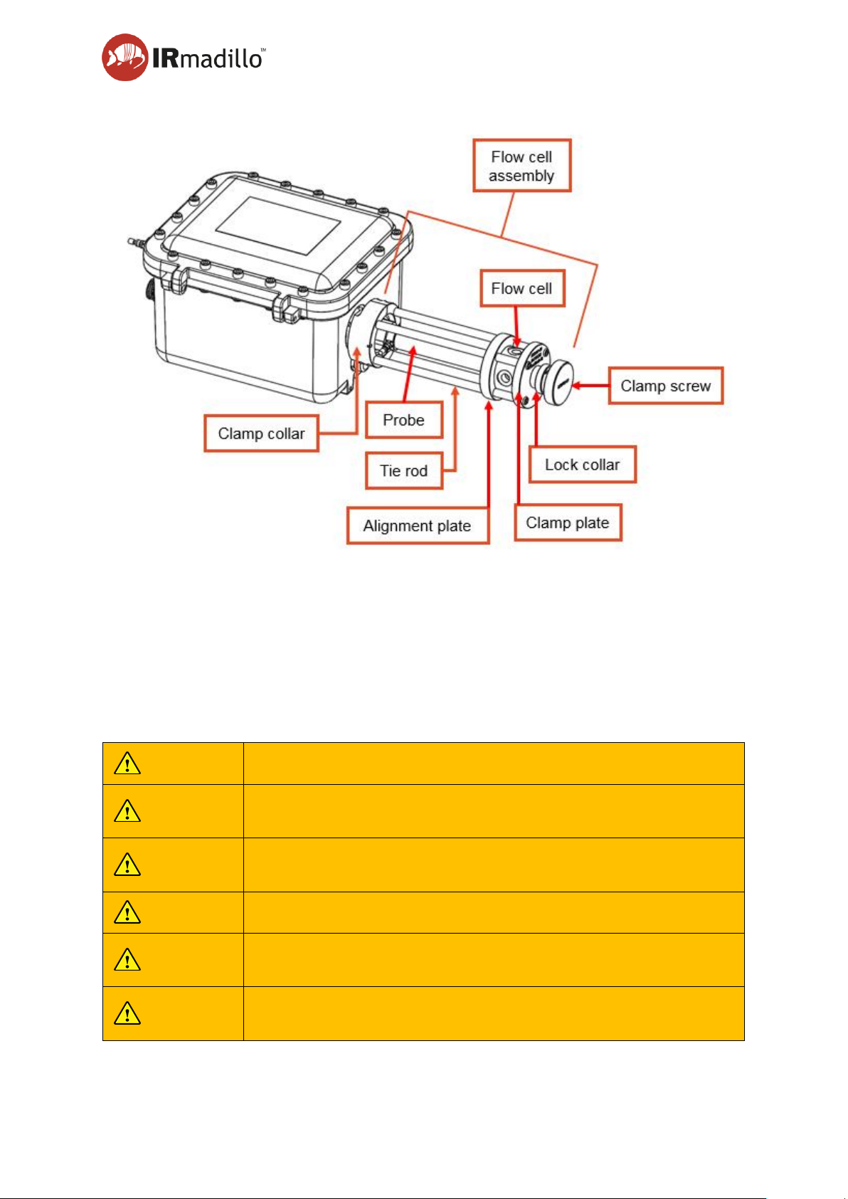
User Manual Page 86
www.keit.co.uk Accessories: DOC0535 (10 July 2019, 16:56)
Back to Table of Contents
8.2 Flow cell
8.2.1 Introduction
The flow cell assembly contains a pressure vessel and has been designed to withstand the
analyte conditions that are specified on your product label. For detailed drawings, see
Appendix 3: Technical Drawings IRmadillo.
It is important to follow these instructions completely to ensure safe use of the flow cell.
8.2.2 Safety
WARNING
The flow cell assembly contains a pressure vessel.
WARNING
Do not exceed the pressure / temperature ratings stated on the
IRmadillo label.
WARNING
Visually inspect the assembly for signs of wear and tear before
use.
WARNING
Ensure that the flow cell is depressurised before disassembly.
WARNING
The flow cell parts will reach the same temperature as the
analyte.
WARNING
Tighten all fasteners to the required torque using a calibrated
torque wrench; do not overtighten.
Page 87

User Manual Page 87
www.keit.co.uk Accessories: DOC0535 (10 July 2019, 16:56)
Back to Table of Contents
WARNING
Fit protective devices to your analyte flow circuit to prevent
pressure spikes that exceed the permissible values.
CAUTION
The flow cell has restricted passages so liquids with suspended
particles may cause blockages.
CAUTION
Ensure that the ¼” NPT fittings are attached prior to final
assembly; this avoids any side loads on the IRmadillo
spectrometer which may cause damage.
Prevent load being applied to the instrument by the installation. Connections must not apply
forces to the flow cell or the IRmadillo dip probe. Such loads increase the likelihood of leakage
and could cause the spectral performance of the instrument to become inconsistent.
8.2.3 Specifications and safety limits (flow cell)
Pressure: ..................................... refer to IRmadillo product label
Analyte Temperature: ................... refer to IRmadillo product label
Fasteners tightening torque: .......... 8.7Nm (Unless Noted Otherwise)
Body Material: .............................. Hastelloy C-276
Other Materials: ............................ Stainless Steel, PTFE, Phosphor Bronze.
O-ring seal: .................................. FFKM
Port Size: ..................................... 1/4" NPT
Page 88
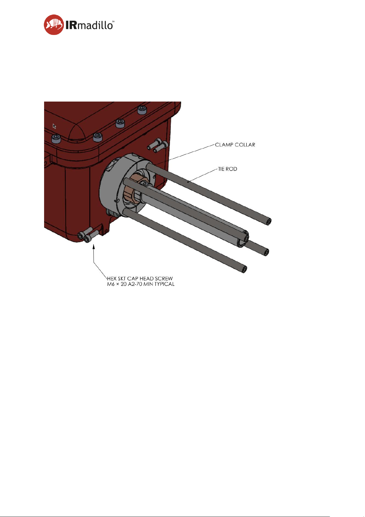
User Manual Page 88
www.keit.co.uk Accessories: DOC0535 (10 July 2019, 16:56)
Back to Table of Contents
8.2.4 Installation
Ideally, 50cm radius clear space around the flow cell should be provided to accommodate
room to fit the components and allow for bends in the piping during fitting. Observe local
manual-handling practice.
Step 1. Assemble the clamp collars, with tie rods fitted, around the dip probe cable gland
nut and fit 4-off M6 x 20 A2-70 cap head screws finger tight only. Ensure that the
collars are not exerting any radial load on the gland nut, that their faces are in contact
with each other and that the enclosure breather beneath the dip probe gland is not
fouled by the clamps. Tighten all four screws to 8.7Nm.
Step 2. Fit the PTFE alignment plate to the flow cell with the tapered bore facing outwards
and secure with 4-off M6 x 20 A2-70 cap head screws and tighten to 8.7Nm.
Page 89
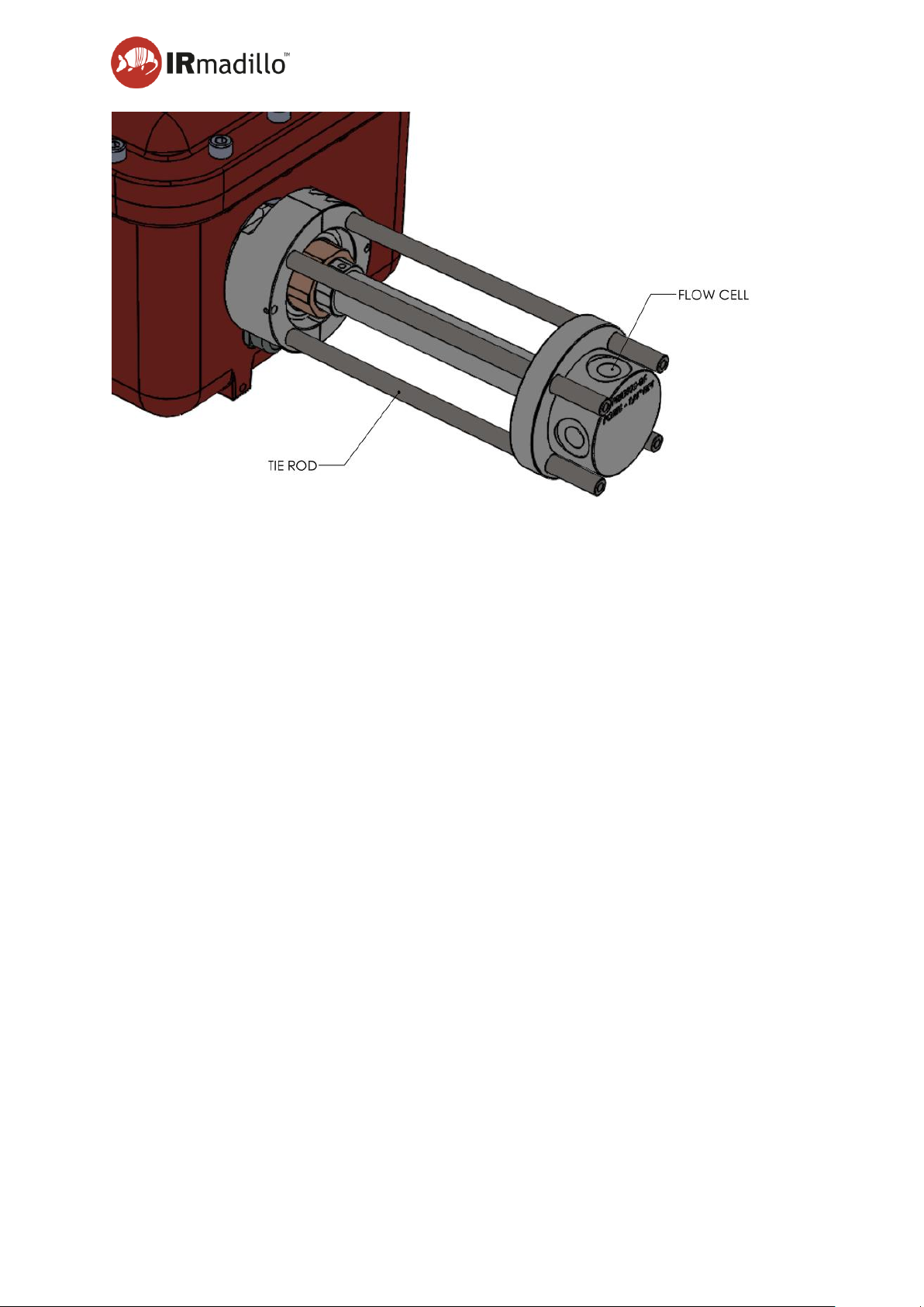
User Manual Page 89
www.keit.co.uk Accessories: DOC0535 (10 July 2019, 16:56)
Back to Table of Contents
Step 3. Fit the flow cell over the tie rods and dip probe, positioning the connection ports
to suit while ensuring that one port is uppermost to allow for bleeding of gas from
the system (if needed). Take care to avoid damaging the ATR element on the tip of
the dip probe.
Page 90
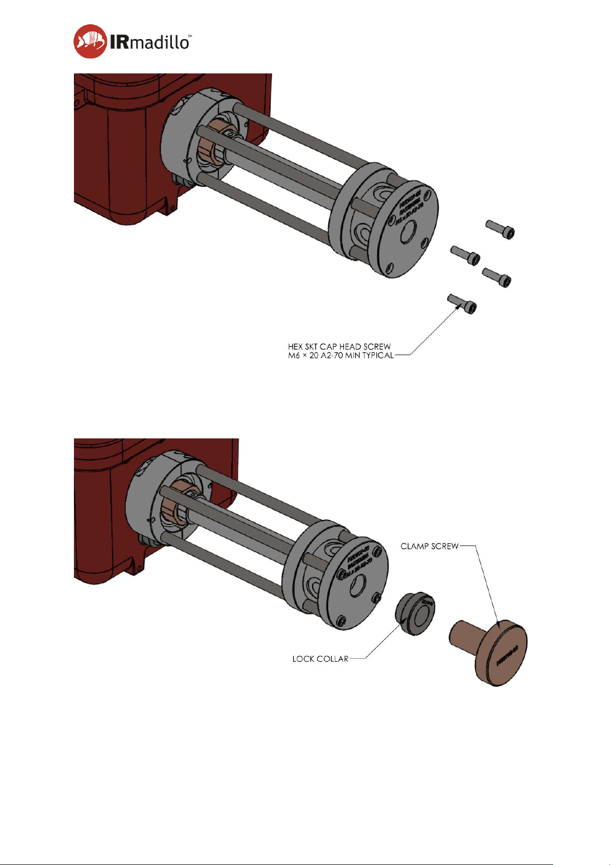
User Manual Page 90
www.keit.co.uk Accessories: DOC0535 (10 July 2019, 16:56)
Back to Table of Contents
Step 4. Fit clamp plate to tie rods with 4-off M6 x 20 A2-70 cap head screws and tighten the
screws to 8.7Nm.
Step 5. Ensure that the connection ports are still in the required orientation. Fit clamp screw
and lock collar, with collar backed off fully, to central tapping in the clamp plate.
Page 91
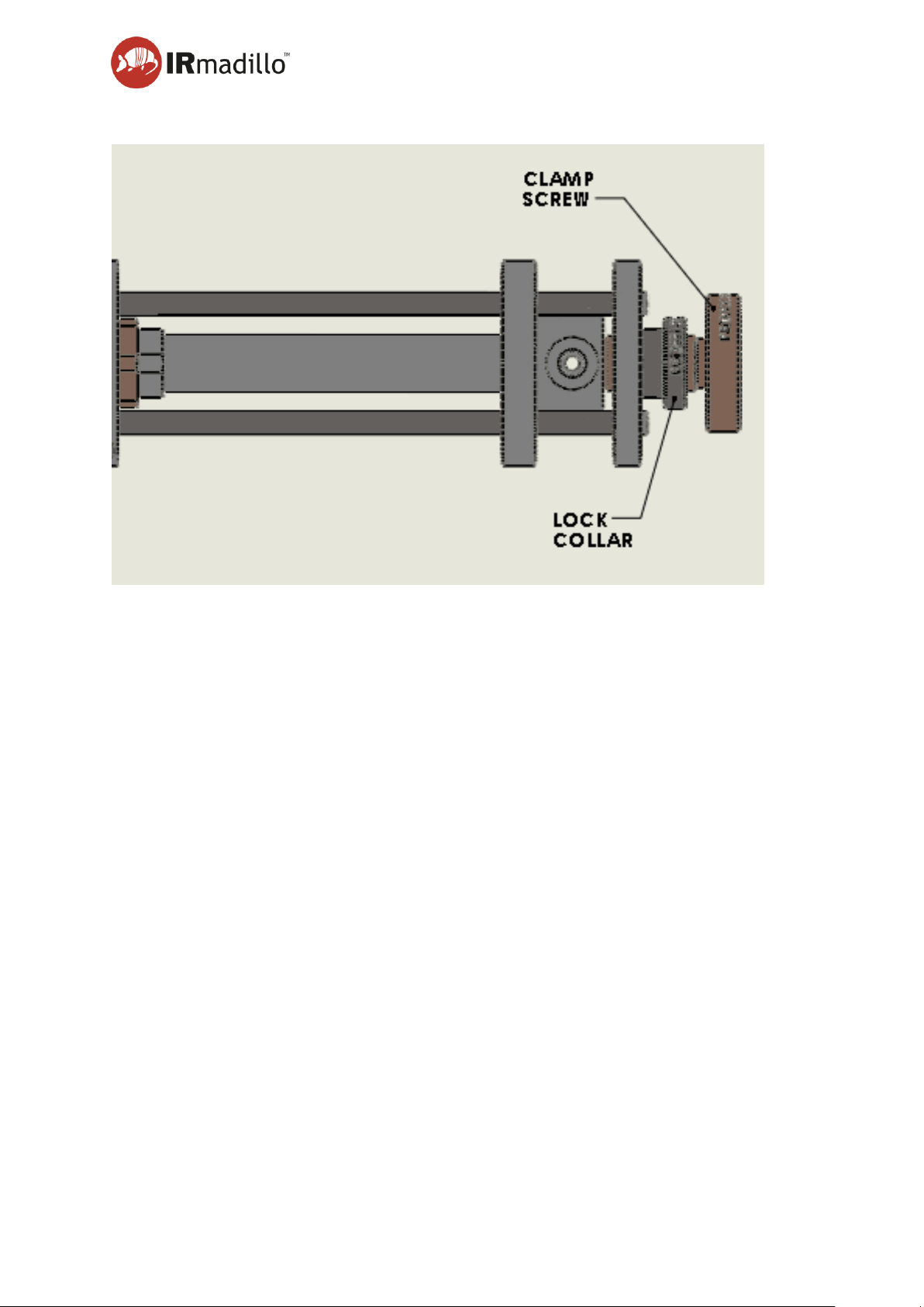
User Manual Page 91
www.keit.co.uk Accessories: DOC0535 (10 July 2019, 16:56)
Back to Table of Contents
Step 6. Tighten the clamp screw hand tight to seat the dip probe fully into the flow cell. Back
off the clamp screw by half a turn and tighten the lock collar finger tight.
Step 7. Fit a suitable plug or bleed valve to the uppermost port in the flow cell to provide for
bleeding gas from the system.
Step 8. Fill the flow cell and pipework with fluid from the process and ensure that the flow cell
is completely bled of all gas by either opening the bleed valve, loosening the plug or
by running the flow (depending on how the system has been configured).
8.2.5 Maintenance
O-ring replacement
The sealing O-ring in the flow cell is manufactured from FFKM, which is an elastomer with
very high chemical resistance.
Inspect the O-ring regularly and replace if there is any suspicion that it may have been
degraded; use plastic forceps to remove the O-ring. This is particularly important if the
chemistry that you are flowing through the probe is known to cause swelling of the O-ring
elastomer, or if the flow cell is often removed to facilitate cleaning.
Regularly check fastener tightness using a calibrated torque wrench.
Page 92

User Manual Page 92
www.keit.co.uk Accessories: DOC0535 (10 July 2019, 16:56)
Back to Table of Contents
8.2.6 Cleaning
The flow cell may be cleaned using standard laboratory cleaning practices as appropriate for
your reaction. The entire flow cell assembly, including the O-ring and fasteners are also
compatible with standard autoclave procedures.
Page 93
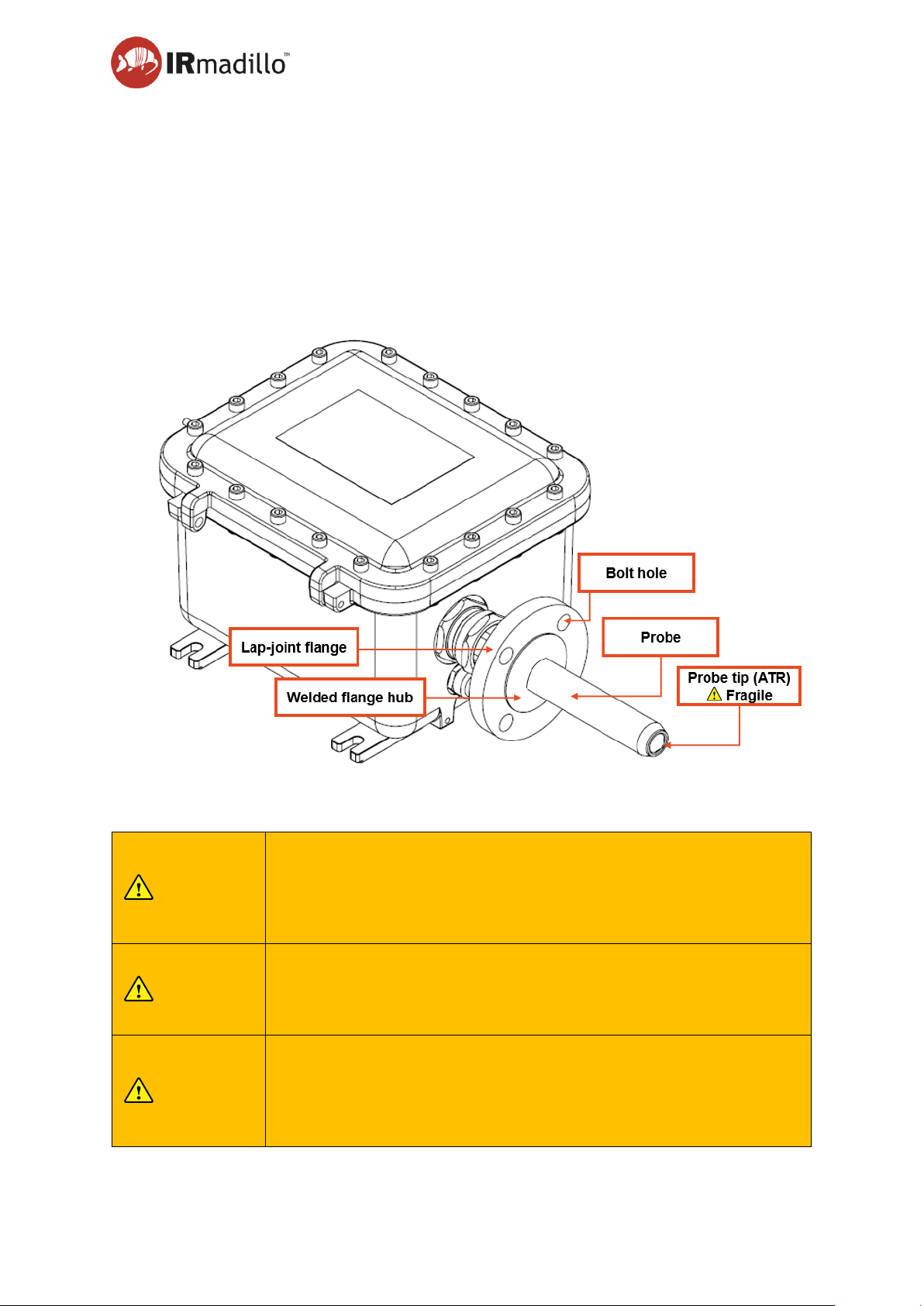
User Manual Page 93
www.keit.co.uk Accessories: DOC0535 (10 July 2019, 16:56)
Back to Table of Contents
8.3 Flanged probe (Ex certified)
8.3.1 Introduction
A version of the IRmadillo spectrometer probe ( 31 mm) is available to allow connection to
process pipework with an ANSI/ASME B16.5 or EN 1092-1 compliant flange. A hub is welded
to the wall of the probe and a compatible lap-joint flange is mounted between the hub and
spectrometer body to permit clamping to process pipework. For detailed drawings, see
Appendix 3: Technical Drawings IRmadillo
It is important to follow these instructions completely to ensure safe use of the flanged probe.
8.3.2 Safety
WARNING
The flange and hub form a seal with the process pipework and as
such are safety critical to prevent an accidental discharge of the
process media. Keit recommends regular inspection of the
integrity of the welds on the front and rear in line with local safety
procedures.
CAUTION
The spectrometer weighs ~18kg. The flange must not be used to
support the instrument on process pipework. Doing so is outside
the scope of the Ex certificate and risks excess stress on the
piping system.
WARNING
The welded flange hub has been tested for safe use at a maximum
pressure of 20bar. Note that the lap-joint flanges and supporting
pipework must have their working pressure de-rated if operating
at temperatures >38°C in accordance with the relevant standard
(ANSI/ASME B16.5 or EN 1092-1).
Page 94
User Manual Page 94
www.keit.co.uk Accessories: DOC0535 (10 July 2019, 16:56)
Back to Table of Contents
8.3.3 Specifications and safety limits (welded flange probe)
Pressure: ..................................... 20bar (maximum)
Analyte Temperature: ................... Refer to IRmadillo product label
Probe Body Material ..................... Hastelloy C276
Welded-Hub Material: .................. Hastelloy C276
Lap-Joint Flange Material: ............. Hastelloy C276 or Stainless steel
Gasket Material: ............................ Customer supplied. Material must be to specification of
standard ANSI B16.21 or EN equivalent
Port Size: ..................................... Nominal pipe size: 1.5 or 2 inches (model dependent)
8.3.4 Installation
The sealing face on the probe requires a gasket to mate against the flange on the process
pipework. The gasket material must be chosen to be compatible with the pressure and
temperature range of the process media, and must be chemically compatible.
WARNING
Choice of gasket material must be appropriate for the chemistry
and process being used.
The probe body and hub are manufactured from Hastelloy, which is resistant to many
aggressive chemicals. However, you are advised to check with Keit before installing on
a new process.
The lap-joint flange behind the flange may be manufactured from Hastelloy or stainless steel.
Care should be exercised to ensure that it is not corroded by aggressive chemicals during
maintenance or installation.
Before beginning installation, ensure that the gasket is in good condition and that the sealing
faces are not scratched or dented.
Take great care to prevent the sensing tip of the probe from damage. It is fragile and easily
chipped.
Support the spectrometer on a suitable mounting frame that aligns the probe with the flange
port that it will be fitted to. Avoid applying stress to the probe, weld or flange by ensuring that
the sealing face of the hub sits flush against the gasket and sealing face of the mating flange
before fitting any mounting bolts to the flange.
Page 95
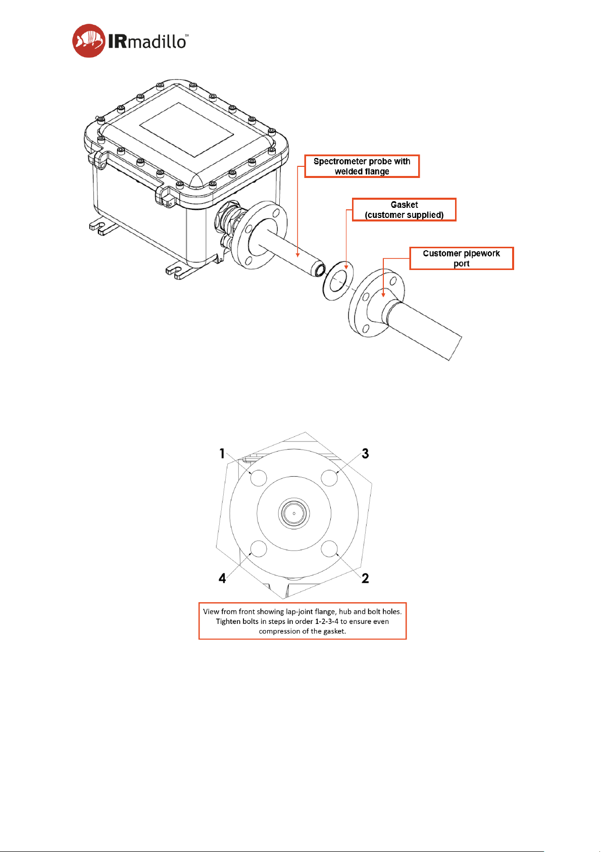
User Manual Page 95
www.keit.co.uk Accessories: DOC0535 (10 July 2019, 16:56)
Back to Table of Contents
Once the spectrometer is aligned with the port, fit appropriate bolts as specified in the relevant
standard, and tighten in stages in the order shown below.
Ensure that the bolts are sufficiently tight to prevent a leak from your pipework.
Page 96

User Manual Page 96
www.keit.co.uk Accessories: DOC0535 (10 July 2019, 16:56)
Back to Table of Contents
8.3.5 Maintenance
Keit recommends regular inspection of the integrity of the welds on the front and rear in line
with local safety procedures.
Inspection of the sealing weld will require removal of the flange and spectrometer from the
pressure vessel and can be completed as part of regular inspection/maintenance of the
spectrometer and pipework.
When removing the bolts, flange and probe, exercise care to ensure that the tip of the probe
is not bumped into pipework or other infrastructure. The tip is fragile and can be damaged by
impact, which will cause a change in system performance. Do not use impact (e.g. a hammer)
to separate components if the gasket becomes stuck to the flange and hub.
The flange is not manufactured from Hastelloy (unlike the hub and probe) and care should be
exercised to ensure that it is not corroded by aggressive chemicals during maintenance.
Page 97
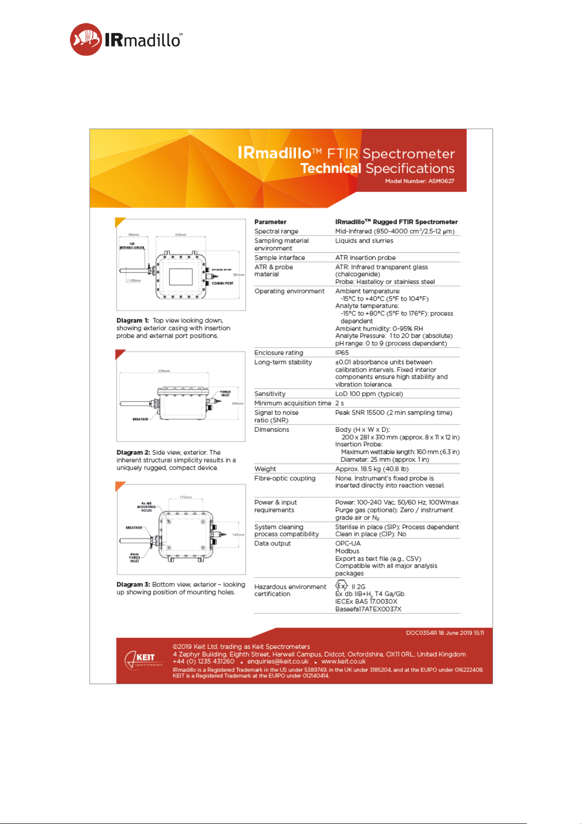
User Manual Page 97
www.keit.co.uk Appendix 1: DOC0535 (10 July 2019, 16:56)
Back to Table of Contents
Appendix 1: Technical Specification Sheet (Model ASM0627, Ex-Certified IRmadillo)
Page 98

Page 98
www.keit.co.uk Appendix 2: DOC0535 (10 July 2019, 16:56)
Back to Table of Contents
Appendix 2: Controller Specifications
Operating System Configuration
Embedded Computer. The controller is not a general-purpose PC and care should be taken
if additional software is to be installed on it. Changes to the configuration may affect the
performance of the spectrometer.
User Accounts. There are two user accounts, one with system administrator privileges and
a second ‘standard’ user. The standard user account starts automatically and is the default
account for the Keit Spectrometer Application. The system administrator account is provided
so that the end user can change the operating system configuration or install additional
software if that is required.
Windows Updates. This is disabled by default. It is for the local administrator to choose
when to update the operating system. A strategy will be required to manage updates
particularly if the controller is networked.
Anti-virus. There is no anti-virus installed. The controller should only be connected to internal,
protected networks. The end-user may install their own anti-virus as required.
BIOS configuration
The BIOS is password protected and booting from USB is disabled by default.
Physical details
Parameter / Feature
Description
Dimensions
The controller measures 280 x 85 x 192mm and is provided
with optional mounting adaptors to fit a 2u 19” rack.
Operating Environment
The controller must be operated in a safe, non-explosive
environment.
• Operating Temperature: 0° to 50°C
• Humidity: 5% to 90% at 25°C
Monitor Resolution
The recommended monitor resolution is 1280 x 1045 pixels or
higher.
Page 99
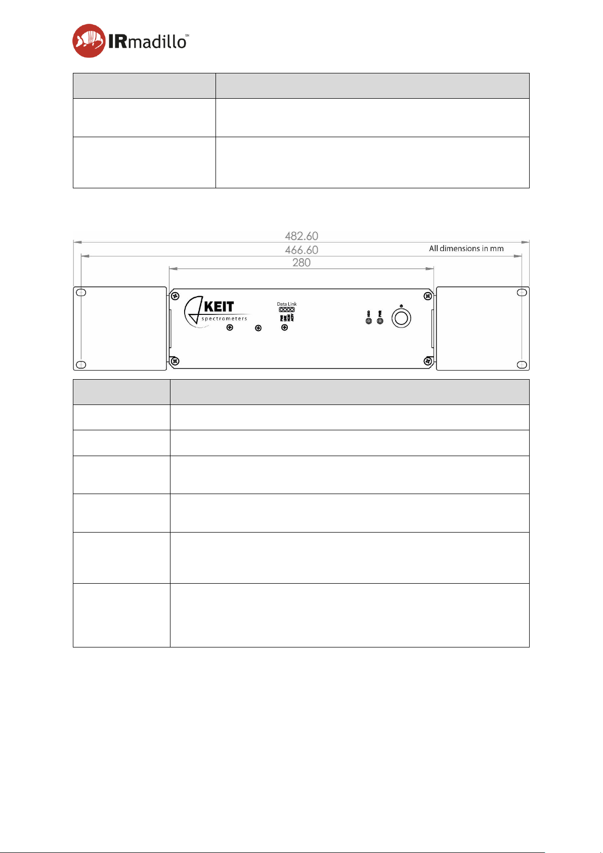
User manual Page 99
www.keit.co.uk Appendix 2: DOC0535 (10 July 2019, 16:56)
Back to Table of Contents
Parameter / Feature
Description
Mains Power Requirement
90 to 264 Volts AC, 47 to 63Hz. Internal controller requirement
is 20W and the internal power supply is rated to 60W.
Fibre-Optic Link
The data communications between the controller and the
spectrometer are provided by a Duplex LC multimode fibreoptic cable which is supplied by Keit.
Front panel
Indicator Label
Function
HDD
Hard Disk Active
PWR
Power is Supplied
ICRON - PWR
Blue LED turns on when power is supplied. Off when no power is
supplied.
ICRON – Link
Green LED Indicates a valid fibre optic link is established between the
controller and the spectrometer.
ICRON – Host
Green LED Indicates that the Fibre Optic link to the spectrometer is
properly connected within the controller. The LED blinks when in
suspend state.
ICRON - ACTV
Amber LED Indicates activity when data transmission is active between
the controller and the spectrometer.
Page 100
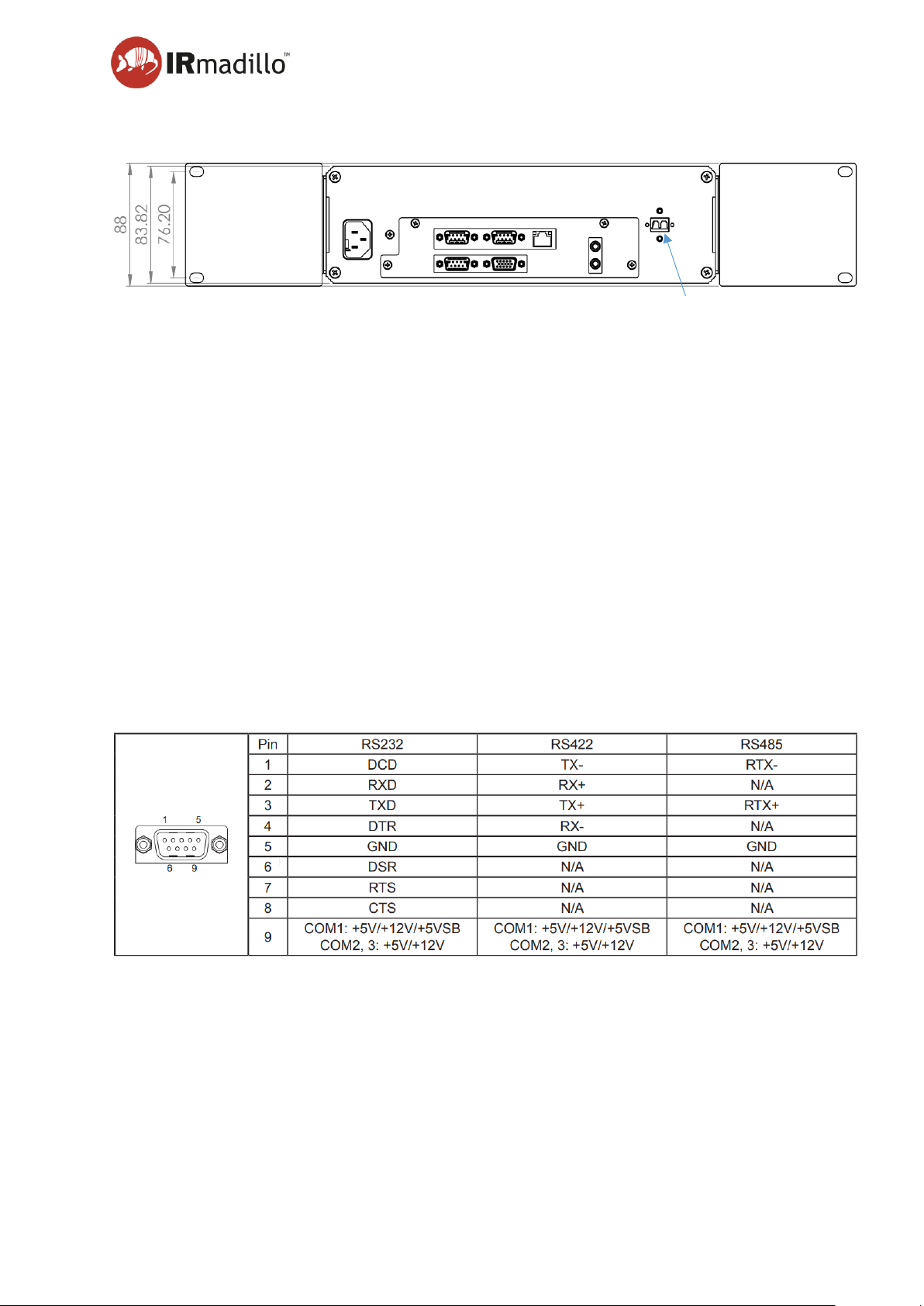
User manual Page 100
www.keit.co.uk Appendix 2: DOC0535 (10 July 2019, 16:56)
Back to Table of Contents
Rear panel
Connections are provided for:
• Human-Machine Interface: 1x VGA, 1x HDMI, PS2 keyboard, PS2 Mouse, Mic-in &
Line-out.
• USB:4 (2x USB3.0, 2x USB2.0),
• Networking: 2x Gigabit LAN/ Ethernet,
• Serial Data:3 x RS232/422/485 COM ports.
• Mains Power Input.
If required a blanking plate (shown fitted) is provided to prevent local user interaction. It covers
1x Ethernet, 4xUSB, 2xPS2 and HDMI.
Wiring Pin Out for COM Ports
The COM ports are terminated in industry standard 9 Way Male D-sub Connector Plugs. The
COM ports are configured in the BIOS by default to RS485, however RS232 and RS422 may
also be made available if required.
Fibre Optic to
Spectrometer
All dimensions in mm
 Loading...