

KEEWAY QJ50T-21U Maintenance Manual

1
Motorcycle QJ50T-21U
Maintenance Manual
Qianjiang Motor Corporation Ltd.

2
Contents
Contents ....................................................................................................................................................................... 2
Preface ......................................................................................................................................................................... 5
Preparing Documents........................................................................................................................................... 6
Inspection/Adjustment ....................................................................................................................................... 38
Inspection and Maintenance of Electrical System ..................................................................................................... 51
I. Battery/Charging System........................................................................................................................................ 54
1.1 Preparing Documents ................................................................................................................................... 54
1.2 Failure diagnosis .......................................................................................................................................... 55
1.3 Battery ......................................................................................................................................................... 56
1.4 Charging System .......................................................................................................................................... 57
1.5 Voltage/Current Regulator ........................................................................................................................... 58
1.6 Magnetor charging coil ................................................................................................................................ 59
1.7 Magnetor Lighting Coil ............................................................................................................................... 59
II. Ignition System ..................................................................................................................................................... 62
2.1 Preparing Documents ................................................................................................................................... 62
2.2 Failure Diagnosis ......................................................................................................................................... 63
2.3 Ignition System Check ................................................................................................................................. 64
2.4 CDI Group ................................................................................................................................................... 65
2.5 Ignition Coil ................................................................................................................................................. 66
2.6 Trigger ......................................................................................................................................................... 67
III. Startup System ..................................................................................................................................................... 69
3.1 Preparing documents ................................................................................................................................... 69
3.2 Failure diagnosis .......................................................................................................................................... 70
3.3 Startup Motor ............................................................................................................................................... 70
3.4 Starter Relay ................................................................................................................................................ 72
IV. Bulbs/Switches/Meters ........................................................................................................................................ 75
4.1 Preparing documents ................................................................................................................................... 75
4.2 Failure Diagnosis ......................................................................................................................................... 75
4.3 Replacement of Headlamp Bulbs ................................................................................................................ 75
4.4 Replacement of front steering lamp bulbs ................................................................................................... 76
4.5 Replacement of tail lamp bulbs ................................................................................................................... 76
4.6 Meter ............................................................................................................................................................ 77
4.7 Main Switch ................................................................................................................................................. 77
4.8 Horn ............................................................................................................................................................. 78
4.9 Handlebar Switch......................................................................................................................................... 78
Inspection and Maintenance of the Chassis ............................................................................................................... 79
5. Brake ...................................................................................................................................................................... 82
5.1 Maintenance Instruction .............................................................................................................................. 82
5.2 Failure Diagnosis ......................................................................................................................................... 82
5.3 Front Disc Brake .......................................................................................................................................... 83
5.4 Rear Drum Brake ......................................................................................................................................... 85

3
6. Body ...................................................................................................................................................................... 88
7. Front Wheel / Front Suspension ............................................................................................................................ 92
7.1 Preparing Documents ................................................................................................................................... 92
7.2 Failure Diagnosis ......................................................................................................................................... 92
7.3 Front Wheel ................................................................................................................................................. 93
7.4 Steering Handle ........................................................................................................................................... 95
7.5 Front Fork .................................................................................................................................................... 96
8. Rear Wheel/Rear Suspension............................................................................................................................... 100
8.1 Preparing Documents ................................................................................................................................. 100
8.2 Failure Diagnosis ....................................................................................................................................... 100
8.3 Rear Wheel ................................................................................................................................................ 101
8.4 Rear Absorber ............................................................................................................................................ 102
9.Fuel Tank/Seat ...................................................................................................................................................... 106
9.1 Preparing Documents ................................................................................................................................. 106
9.29.2 Failure Diagnosis .................................................................................................................................. 106
9.3 Fuel Tank/Seat ........................................................................................................................................... 107
10. Removal and Installation of Motor .................................................................................................................... 109
10.1 Preparation Documents ............................................................................................................................ 109
10.2 Failure Diagnosis ..................................................................................................................................... 109
10.3 Disassembly of Motor .............................................................................................................................. 110
10.4 Installation ............................................................................................................................................... 111
Inspection and Maintenance of Engine .................................................................................................................... 112
11.Lubricaiting System ............................................................................................................................................ 114
11.1 Preparation Documents ............................................................................................................................ 114
11.2 Failure Diagnosis ..................................................................................................................................... 114
11.3 Fuel Pump ................................................................................................................................................ 115
12. Carburetor .......................................................................................................................................................... 118
12.1 Preparing Documents ............................................................................................................................... 118
12.2 Failure Diagnosis ..................................................................................................................................... 118
12.3 Carburetor Disassembly ........................................................................................................................... 119
12.4 Installation and Adjustment ..................................................................................................................... 121
13. Cylinder Cover .................................................................................................................................................. 123
13.1 Preparing Documents ............................................................................................................................... 123
13.2 Failure Diagnosis ..................................................................................................................................... 123
13.3 Cylinder Cover......................................................................................................................................... 123
13.4 Cylinder Cover Check ............................................................................................................................. 124
13.5 Installation of Cylinder Cover ................................................................................................................. 124
14. Cylinder Block and Piston ................................................................................................................................. 126
14.1 Preparing Documents ............................................................................................................................... 126
14.2 Failure Diagnosis ..................................................................................................................................... 127
14.3 Cylinder Block ......................................................................................................................................... 127
14.4 Piston ....................................................................................................................................................... 128
14.5 Piston Installation .................................................................................................................................... 130
15. Drive Face/Clutch/Driven Wheel/Kickstart Mechanism ................................................................................... 133

4
15.1 Preparing Documents ............................................................................................................................... 133
15.2 Failure Diagnosis ..................................................................................................................................... 133
15.3 Left Crankcase Cover .............................................................................................................................. 134
15.4 Drive Face ................................................................................................................................................ 134
15.5 Clutch/Driven Wheel ............................................................................................................................... 136
15.6 Breakdown of Clutch and Driven Wheel ................................................................................................. 137
15.7 Installation ............................................................................................................................................... 140
15.8 Kickstart Mechanism ............................................................................................................................... 141
16. Decelerator ......................................................................................................................................................... 143
16.1 Preparing Documents ............................................................................................................................... 143
16.2 Failure Diagnosis ..................................................................................................................................... 143
16.3 Gearbox ................................................................................................................................................... 143
16.4 Installation ............................................................................................................................................... 144
17. Crankcase........................................................................................................................................................... 146
17.1 Preparing Documents ............................................................................................................................... 146
17.2 Failure Diagnosis ..................................................................................................................................... 146
17.3 Crankcase ................................................................................................................................................. 147
17.4 Installation ............................................................................................................................................... 149
Inspection and Maintenance of Exhaust Emission System ...................................................................................... 150
18. Exhaust Emission & Control System................................................................................................................. 151
18.1 Warranty on the Exhaust Emission & Control System ............................................................................ 151
18.2 Instructions on Periodic Maintenance ...................................................................................................... 151
18.3 Mechanical Function of the Exhaust Control System .............................................................................. 152
18.4 Catalytic Conversion System ................................................................................................................... 152
18.5 Measures when the idle speed emission value exceeds the standard (Two-Stroke) ................................ 154

5
Preface
This maintenance manual is used for operating and maintaining Motorcycle
QJ50T-21U
Preparing Documents include all necessary instructions and statements. Please
carefully read this manual before operation.
Inspection & Adjustment states how to check and adjust your motorcycle. All
safety rules and maintenance regulations shall be carried out from the beginning of
periodic inspection.
Except for Chapter I, the rest chapters explain the disassembly/ assembly/
inspection of engine, entire motorcycle and electrical parts.
Breakdown drawing, systematic drawing, failure analysis and statements are
contained at the first part of each chapter.
Please note that photos, pictures or instructions are for your reference only. The
actual object may differ from this mentioned here. We will not make notification for
any discrepancy.
KEEWAY Motor Corporation Ltd.

6
Preparing Documents
General Safety Maintenance Rules
Specification Table Failure Diagnosis
General Safety
Carbon monoxide
Engine must be started up in a well-ventilated place, not in a closed area.
Note
Exhaust gas contains poisonous carbon monoxide, which may cause unconsciousness or even death of human.
Start up engine in an open place. The exhaust cleaning system shall be adopted if engine is started up in a closed
area.
Petrol
Ventilation is required for working places. Fire is strictly forbidden in any working place or where petroleum is
stored.
Battery
Battery emits explosive gas. Therefore, it shall be far away from fire sources, naked flame or smoking places.
Make sure good ventilation during charging.
Battery contains sulfuric acid (electrolyte). It will burn your skin or eyes when contacted. Therefore, wear
protective clothing and mask.
——Clean with fresh water immediately if electrolyte splashes on the skin.
——Clean with fresh water at least for 15 minutes immediately and then go to the doctor if electrolyte splashes
on eyes.
Electrolyte is poisonous. Drink a large quantity of fresh water, milk, milk of magnesia (laxative antacid) or mineral
oil if electrolyte is swollen accidently. Then go to the doctor. It shall be unreachable for children.
Do not remove the battery during commissioning. Otherwise, it may cause damage to inner parts of the vehicle.

7
Maintenance Rules
Metric tools are preferable for the maintenance of this motorcycle.
Improper tools may cause damage.
Clean up the surface of components or assembly parts before
removing or opening the shield for maintenance, which can
prevent dirt from falling into the engine, chassis or braking
system.
Wash and dry parts with air compressor after disassembly and before measurement of attrition value.
Solvent or oil can easily damage aging rubber articles. Check rubber before reassembly and replace rubber if
necessary.
套:boot
When loosening assembly parts, please start from outside to
inside. Small assembly parts shall be loosened first.
Complex assembly parts, such as gearbox, shall be stored in
proper order for facilitating installation in the future.
Please specially note important connections before disassembly.
Replace parts which will not be in use before disassembly.

8
Bolts and screws with different length shall be separately used for
different assembly parts and shields, and they shall be correctly
mounted. Insert a bolt into a hole to check whether it is proper if
you are confused.
Fill the groove with grease before mounting an oil seal. Check
whether the oil seal is smooth or damaged during assembly.
When installing a hose (fuel, vacuum or cooling agent), insert its
end into the bottom of the connector so that the hose clip can
properly fix the connector. Rubber or plastic dirt-proof boot shall
be mounted at the original design position.
槽:groove 夹子:clip 接头:connector
During dismantling ball bearings, one or two (inside & outside)
bearing rollers shall be supported by tools. Ball bearings may be
damaged during disassembly and have to be replaced if only one
roller (either inside or outside) is imposed with force.
以上两例都会使轴承破裂:Bearings will be broken under either
occasion as mentioned.

9
Loose cables threaten electrical safety. Check each cable after
it is clamped to another for electrical safety;
Wire clamps are not allowed to bend towards welding point;
Bind cables at the designated place;
Do not deploy cables at the end of frame or at sharp point;
Do not deploy cables at the end of bolts or screws;
Cable deployment shall be far from heat source and where
cables may be clamped during moving;
Cables along the handlebar shall be neither too tight nor too
loose, and do not interface with any neighboring parts at
steering positions;
Cables shall be properly deployed without twist or knot;
Check whether the connector jacket is damaged and whether
the connector is over-stretched before mounting connectors;
Adopt adhesive tape or hosepipe to protect cables if they are
positioned at sharp point or corner;
Bind cables with tape after repairing;
Control cables shall not be bent or twisted. Clumsy operation
may be caused in light of damaged control cables.
10
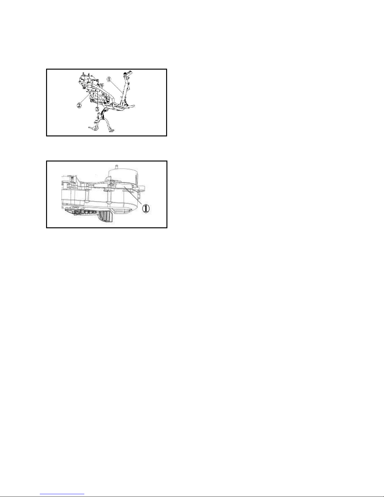
Identification
1. The identification number of motorcycle is marked at the
frame ① : ;BBB941E?????????. The frame sign and the
anti-refitting sticker are fixed at the back of the frame. Take the
view from the back of the frame, the frame sign is fixed at the
left ②and the on the right③. The frame sign is fixed with rivets
and the anti-refitting sticker is sticked with glue.
Fig. 1-1
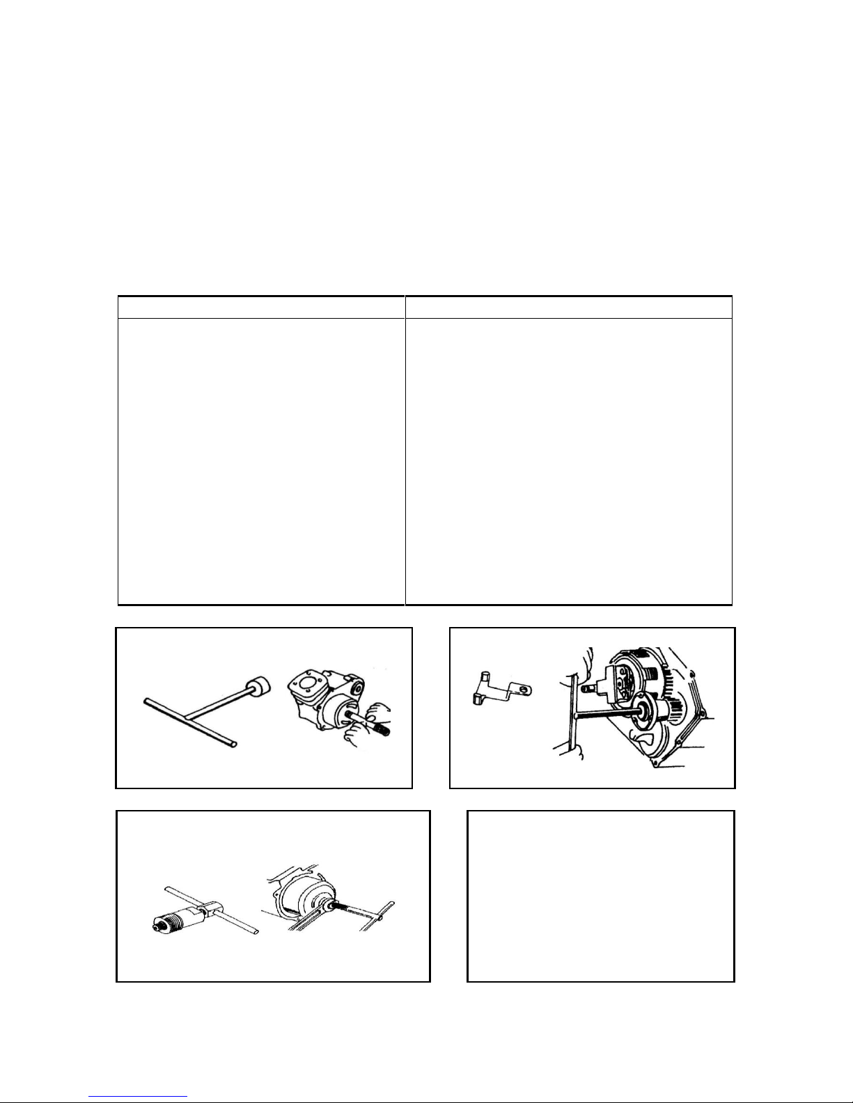
2.The engine serial number① is printed on the shell of
crankcase. See fig. 1-2. The engine serial number is set like:
KW1E40QMB-4*口口口口口口口口*.
Fig. 1-2
Significant Notes
1. Please apply valid Qianjiang parts and accessories. Any part or accessory not in accordance with the design
specification of Qianjiang Company may cause damage to engine.
2. Only metric tools are valid for maintenance and repair. Metric screws, bolts and nuts can not be exchanged with
imperial fasteners.
3. New gaskets, O-rings, cotter pins and locking pieces shall be applied for re-assembly.
4. Bolts with large diameter or positioned inside shall be fastened first and then diagonally screw down until
reaching required torque, otherwise there is special instruction.
5. Wash disassembled parts with cleanser. Lubricate all sliding surface before assembly.
6. Check whether all the parts and accessories are correctly mounted and operated after assembly.
7. Clean and remove oil before measurement. Add recommended lubricant to the lubricating areas during assembly.
8. Apply lubricant to the surface of engine and driving system if they are dismantled for long-term storage, which
can prevent rust and dirt.
11
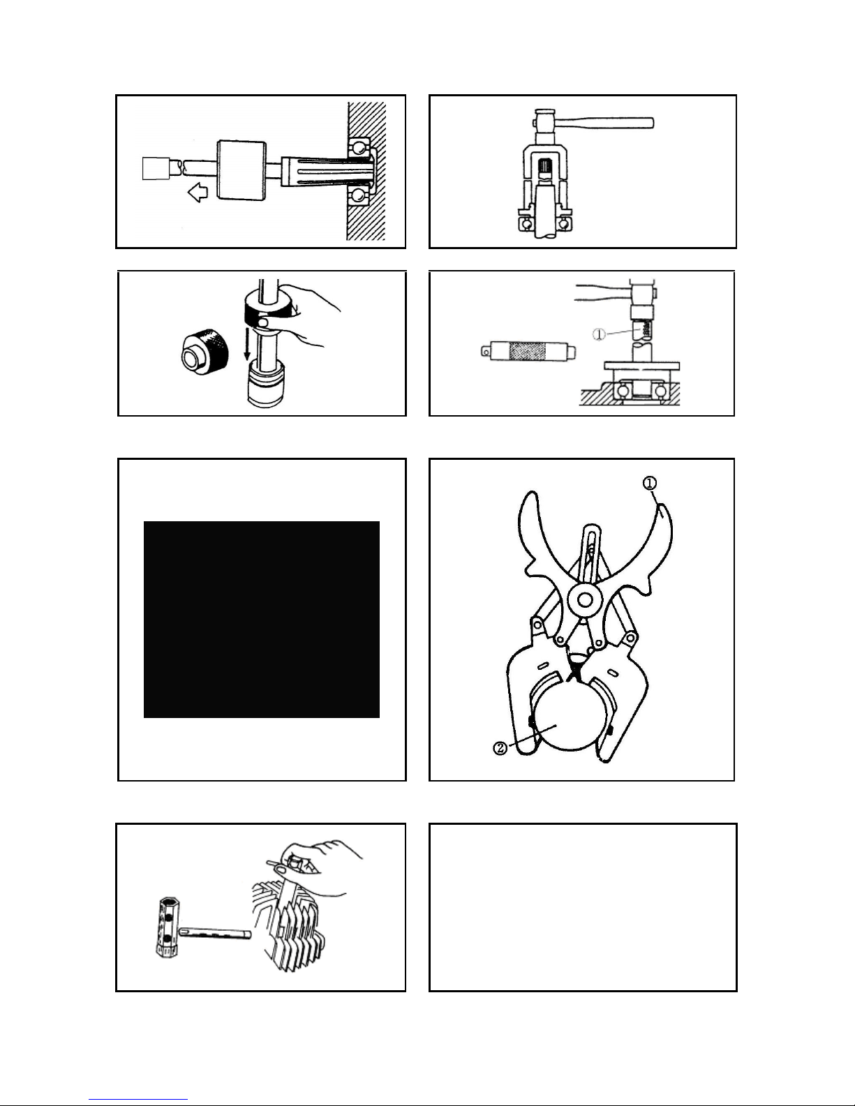
Special Tools
Special tools refer to tools which are specially designed for assembling or disassembling some motorcycle
parts on special positions. Applicable special tools are necessary for precise adjustment and installation. With them,
parts and accessories can be mounted safely, reliably and rapidly, which improves efficiency and saves energy.
1.Tools for repairing the engine
Special tools are required for properly disassembling/assembling some engine parts.
Table and drawing (1-1, 1-2) of special tools for disassembling/assembling engine parts are as follows:
Table 1-1
Name
Remark
Special socket spanner
Clutch clamp holder
Flywheel puller
Feeler gauge
Bearing disassembly tools
Bearing assembly tools
Oil seal remover
Handle for dismantling tools
Piston pin pulling device
Piston pin pliers
Socket spanner for spark plug
Clutch thickness measuring device
Cylinder diameter measuring device
Dial indicator
Used for assembling/disassembling bolts for flywheels, Fig. 1-3
Fig. 1-4
Fig. 1-5
Fig. 1-6
Fig. 1-7
Fig. 1-8
Fig. 1-9
Fig. 1-10
Fig. 1-11
Fig. 1-12
Fig. 1-13
Fig. 1-14
Fig. 1-15
Measuring the inner diameter of piston pin, Fig. 1-16
Table 1-2 (continued)
Fig.1-3 Fig.1-4
Fig.1-5 Fig.1-6 厚度规 (塞尺):feeler gauge
12
Fig.1-7 Fig.1-8
Fig.1-9 Fig.1-10
①handle
Fig.1-11 Fig.1-12
①pliers ②piston
Fig.1-13 Fig.1-14

13
Fig.1-15 Fig.1-16
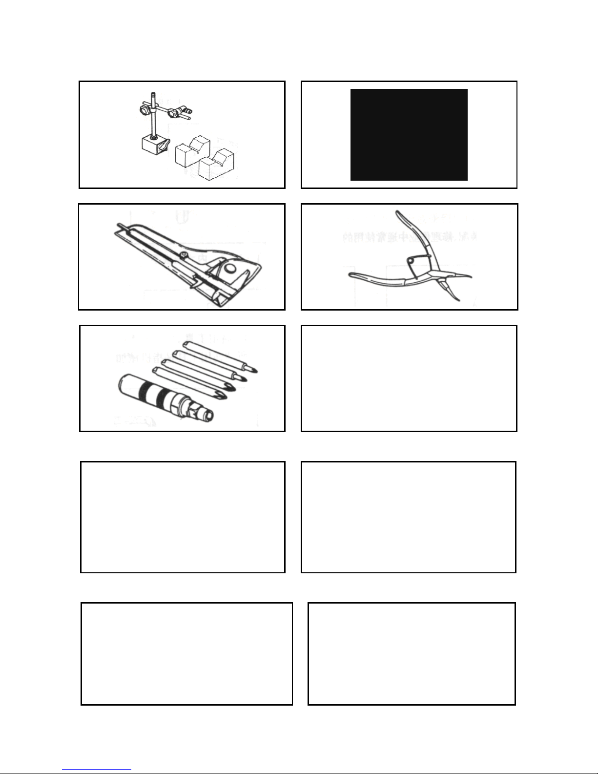
2.Tools for repairing the chassis
Table and drawing (1-17, 1-18) of ordinary tools and special tools for disassembling/assembling chassis parts are
as follows:
Table 1-17
Name
Remark
Torque spanner
Inner hexagon spanner
Socket spanner
Micrometer
Magnetic rack, V-block
Dial indicator
Vernier calipers
Circlip pliers
Screwdriver with striking cap
Tool for assembling oil seal of front fork
Tool for hammering seal of front fork
Steering nut spanner
Fig. 1-19
Fig. 1-20
Fig. 1-21
Fig. 1-22
Fig. 1-23
Fig. 1-24
Fig. 1-25
Fig. 1-26
Fig. 1-27
Fig. 1-28
Fig. 1-29
Fig. 1-30
(1) Ordinary tools for repairing the chassis
Table 1-18 (continued)
Fig.1-19 Fig.1-20
1. socket head 2. crank handle 3. ratchet spanner
14
Fig.1-21 Fig.1-22
Fig.1-23 Fig.1-24
Fig.1-25 Fig.1-26
Fig.1-27 Fig.1-28
(2)Special tools for repairing the chassis: tool for hammering seal of front fork
Fig.1-29
(3)Steering nut spanner
15
Fig.1-30
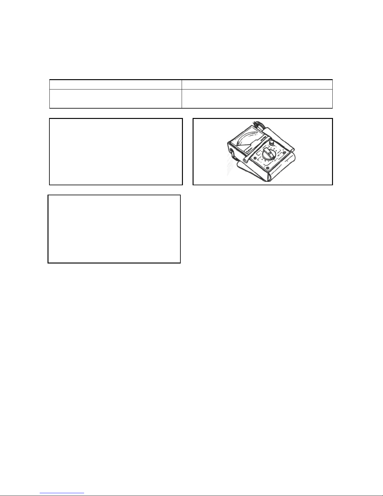
3.Tools for electric parts
Table and drawings (1-31, 1-32) of special tools for testing electric parts are as follows:
Table 1-31
Name
Remark
Multimeter
Ignition tester
Fig. 1-33
Fig. 1-34
Table 1-32 (continued)
Fig.1-33
Fig.1-34
16
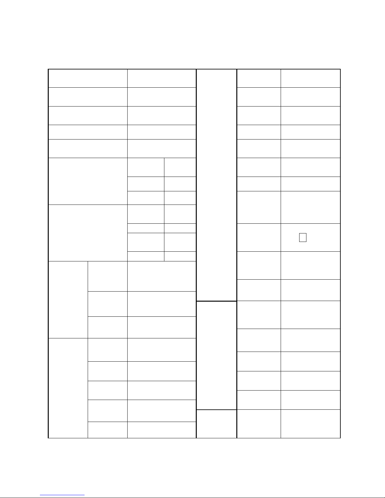
Specification(QJ50T-21U)
Model
QJ50T-21U
Engine
Engine type
QJ1 E40 QMB -4
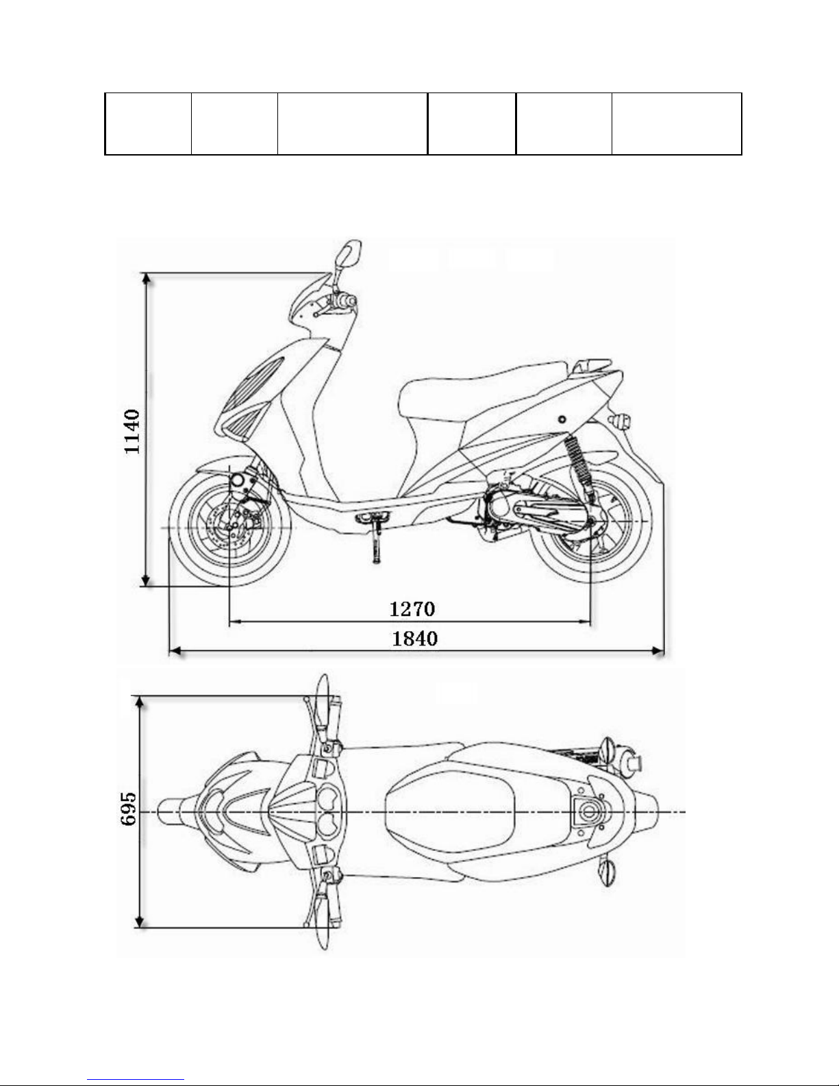
Length mm
1840
Fuel type
Unleaded petrol
(92/95)
Width mm
695
No. of
cylinder
1
Height mm
1140
ID × stroke
49.2×39.2
Wheelbase mm
1270
Total
displacement
50cc
Weight kg
(Curb weight)
Forward
shaft
37
Startup
Electric/kick
Backshaft
55
Cooling
Wind
Total
92
Lubrication
Divided
Tyre
Size
Front outer
tyre
120/70-12
Front rim
3.50×12
Air filter
e4 3XG
Rear outer
tyre
130/70-12
Rear rim
3.50×12
Capacity of
gasoline
tank
5.0L±0.2L
gear
Clutch
Dry centrifugal
clutch
Carburetor
type
IIF-45
Variable
speed gear
Transmission
Stepless
Belt transmission
Performance
Idle speed
-rpm
1800±100rpm/min
Transmission
Belt transmission
Max. torque
4.55N.m/5200rpm
Electric
devices
Battery
capacity/type
12V-3AH/
dry-charged
Max. Hp
2.63kW/5500rpm
Magnetor
capacity
89.6W/5000rpm
Compression
ratio
6.9:1
Spark plug
BR8HSA(NGK)
Max. speed
45km/h
Spark plug
gap
0.6-0.7mm
Braking
system
Dia. of front
brake disc
(mm)
φ190mm
Ignition
CDI
17
I.D. of rear
brake drum
(mm)
φ110mm
QJ50T-21U
18
N Y N Y Y N Y
N
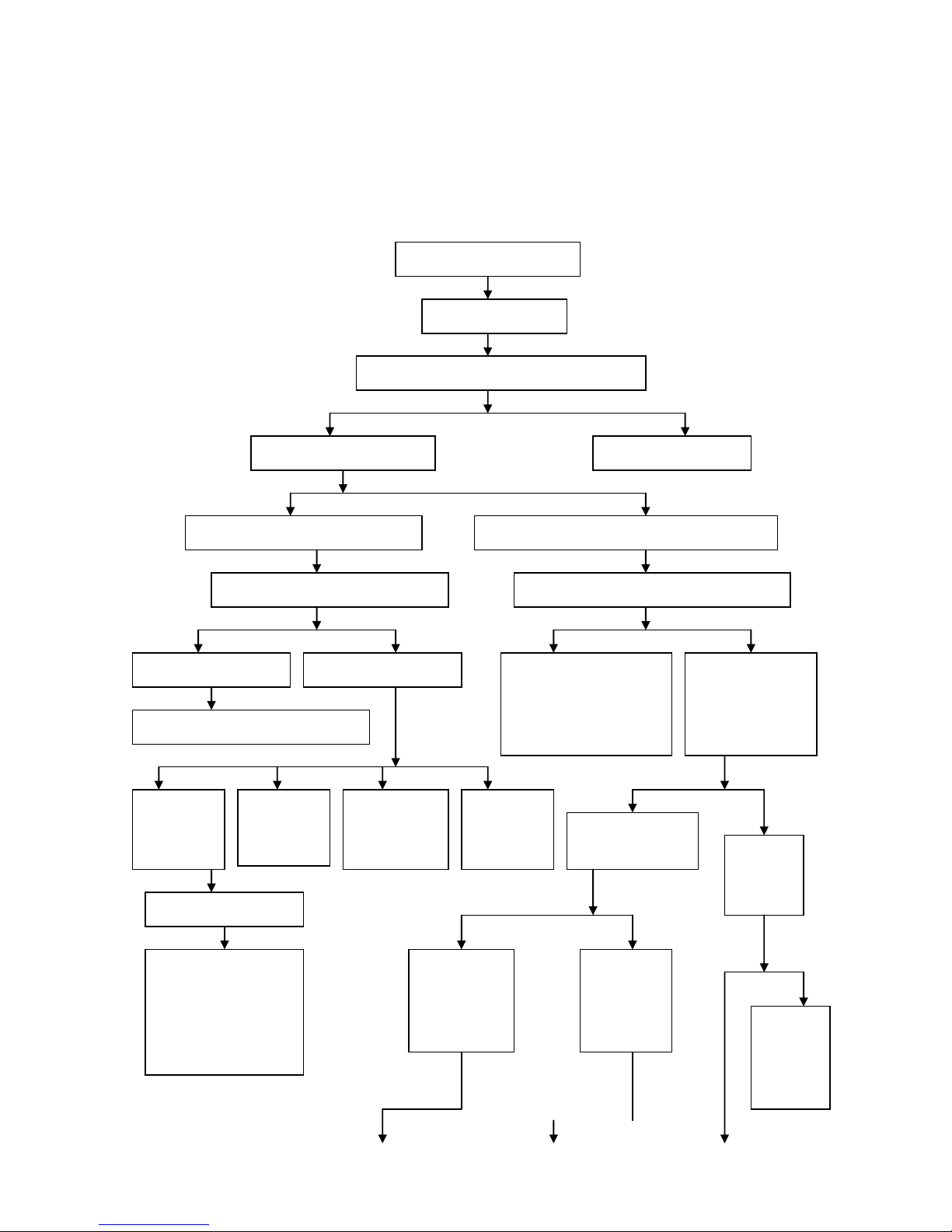
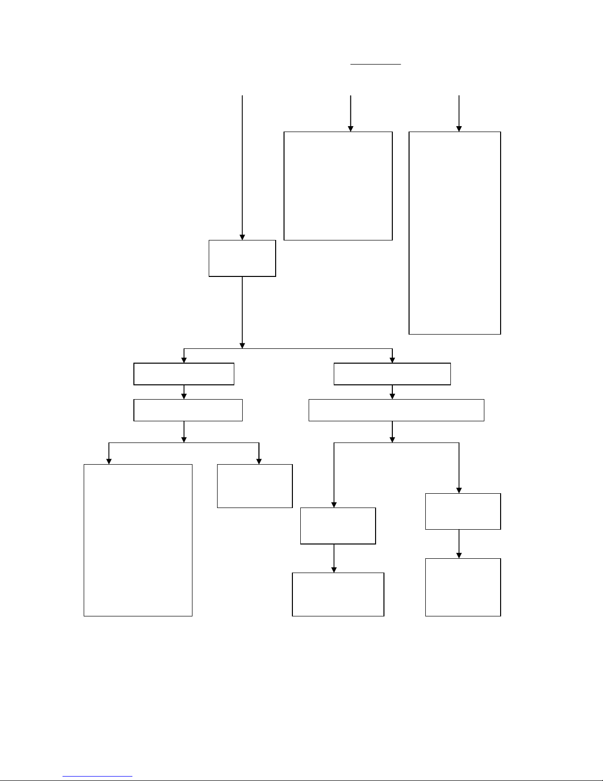
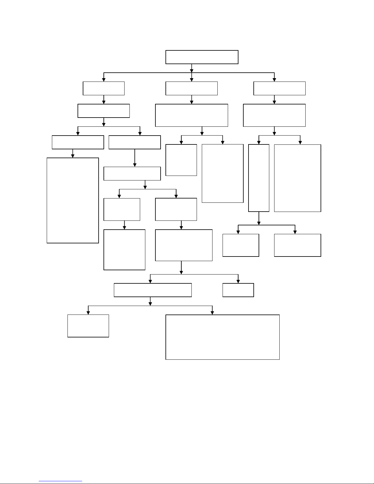
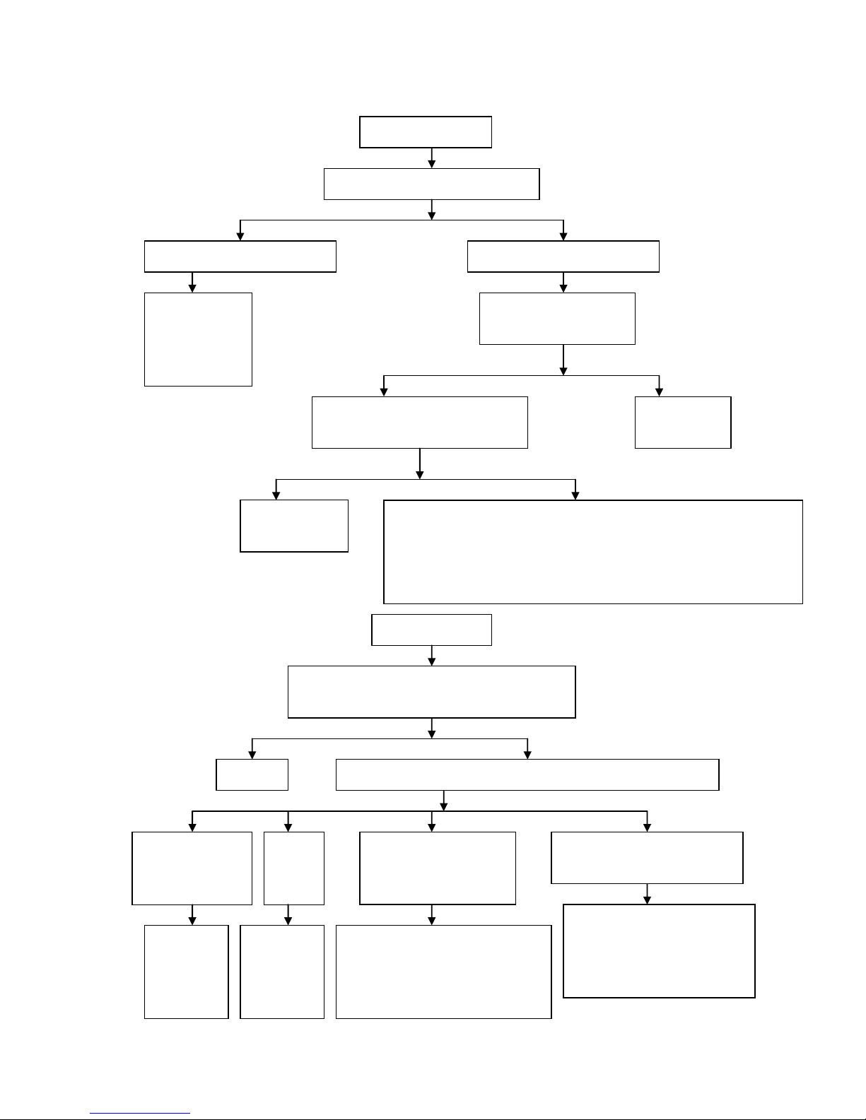
Failure Diagnosis
Diagnosis on failure or difficulty in starting engine
Failure or difficulty in starting
Check ignition system
Remove the spark plug and check whether there is
carbon fouling between electrode.
Sparkover test for spark plug
Eliminate carbon fouling
Weak spark or no spark between electrode
Large blue or bluish purple spark between electrode
Screw off spark plug cap and conduct
sparkover test for high-voltage line
Check whether ignition is timely conducted
with an ignition timing lamp
Large blue spark
Weak spark or no spark
Check whether spark plug and cap are in
good condition
Check power
supply for
ignition
Check whether
short circuit or
open circuit
occurs to
ignition coil
Check whether
short circuit or
open circuit occurs
inside the ignition
system
Check whether
CDI ignition
device is in good
condition
Check the compression
pressure of cylinder
with pressure gauge
Check
whether there
is gasoline in
the fuel tank
Normal
compression
pressure
Insufficient
compression
pressure
Add
gasoline
Non-contact ignition system
for electromagnetic motor
1. Check whether short
circuit or open circuit
occurs to ignition coil
2. Check whether short
circuit or open circuit
occurs to trigger coil
1. Check whether CDI
ignition device is in
good condition
2. Check whether
flywheels and trigger
coil are loosened
Loosen drain screws
of the carburetor
and check whether
there is gasoline in
the overflow pipe
19
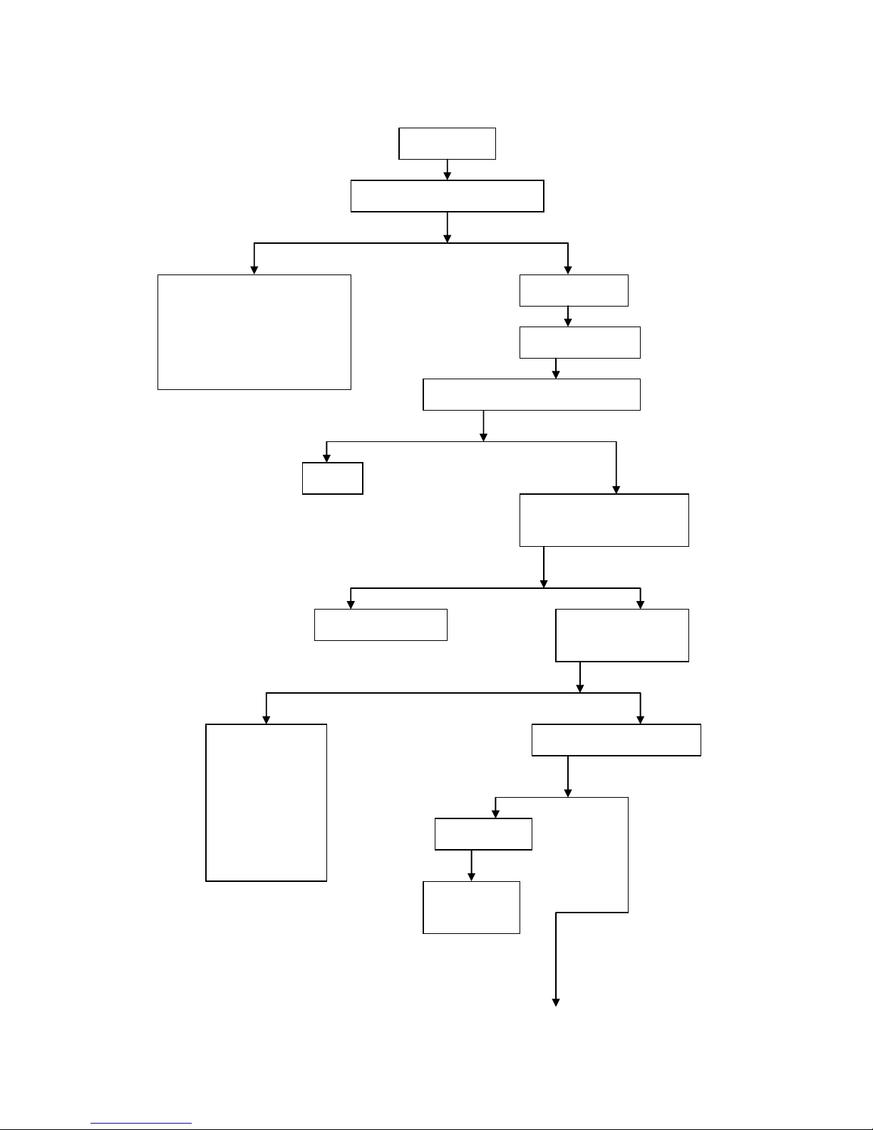
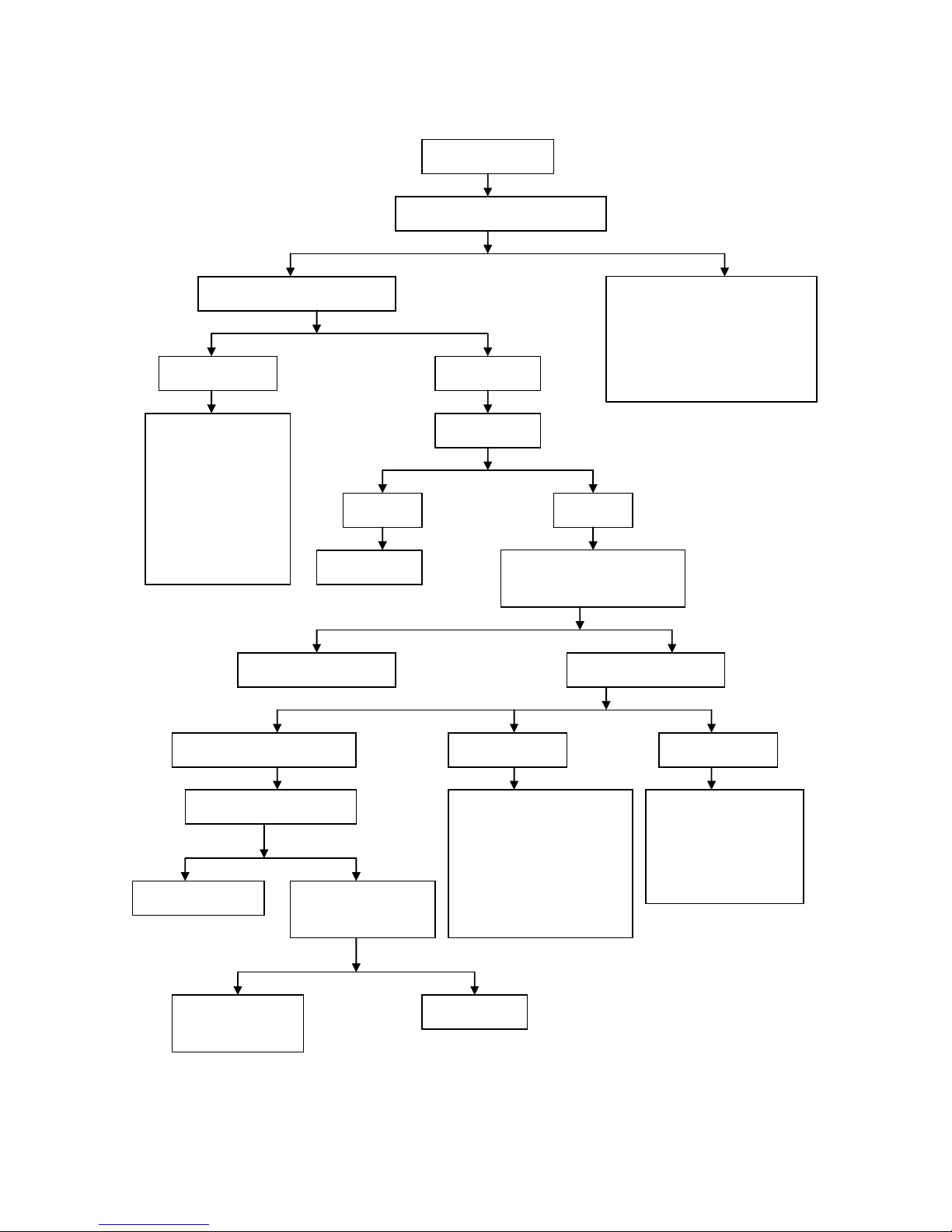
Y
N
Dry electrode of spark plug
Check whether there is oil
spillover in the carburetor
1. Check whether the
float needle valve
and the valve seat are
firmly combined
2. Check whether the
conical surface of
float needle valve is
abrasive as
stepped.
3. Check whether the
carburetor float is
broken
4. Check whether the
carburetor float is too
low
Check whether air
filter is blocked
Flameout shortly
after startup
Continue to work
after startup
The carburetor is blocked
inside or the float is too
high
Startup device of
carburetor (startup &
enrichment system) is
at fault
1. Check leakage on outer
connections of the engine.
2. Check whether the piston
ring is seized in the groove or
whether it has enough
elasticity.
3. Check abrasion of the piston
ring and the cylinder.
1. Check whether the
air vent in fuel tank
cover is blocked.
2. Check whether the
fuel filter and the
fuel switch are
blocked.
3. Check whether the
fuel switch works
normally.
4. Check whether the
oil hole of the
carburetor is
blocked.
5. Check whether the
carburetor float is
too high.
Remove spark
plug and check
20
Y N Y N Y N N Y Y
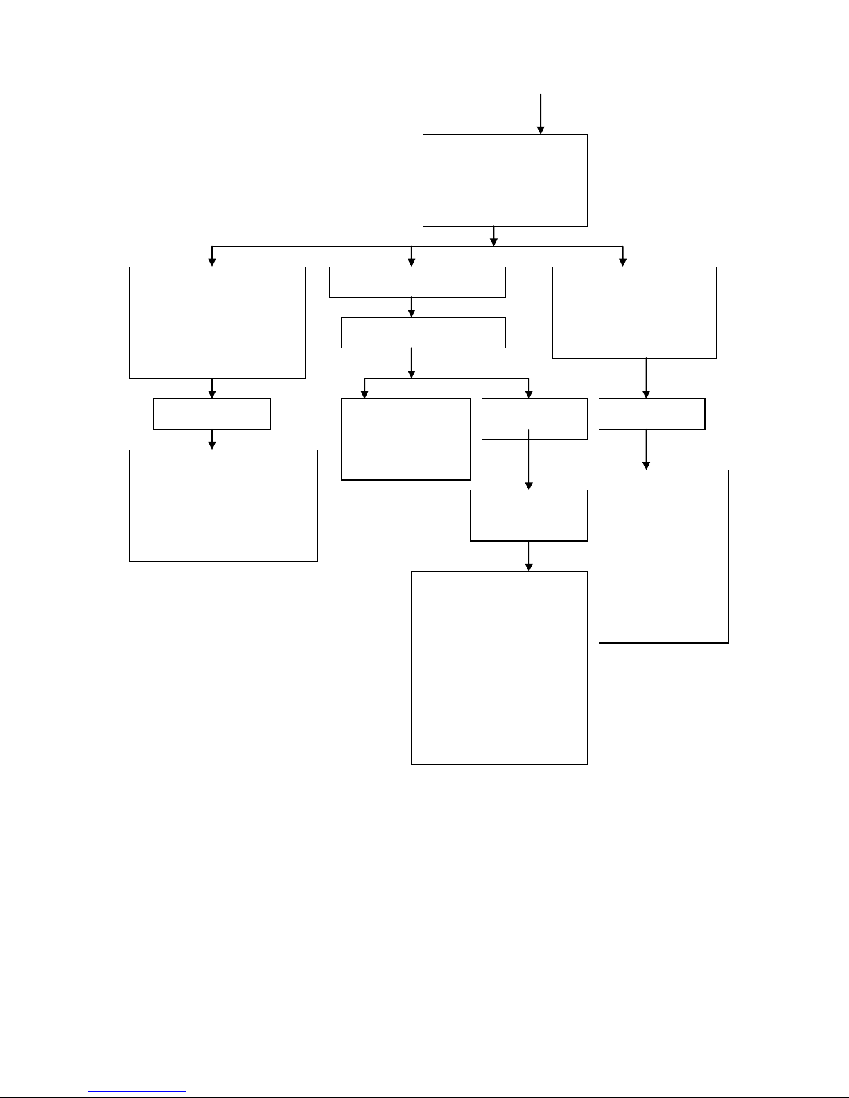
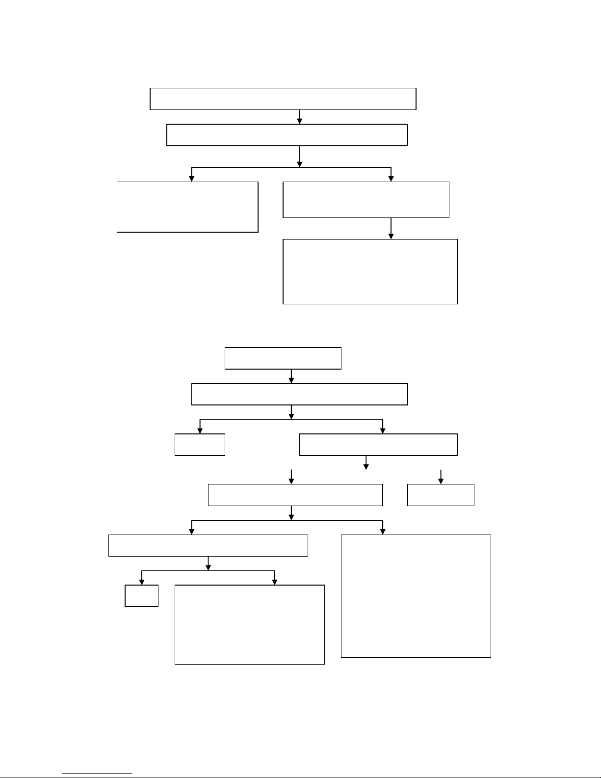
N
Diagnosis on engine overheating
Engine overheating
Check whether operation is correct
1. Check whether gasoline grade is
improper or gasoline is stored for
a long time
2. Check whether the engine works
at high speed for a long time or
with overload during driving
Check cooling system
Air-cooled engine
Check whether heat sink is spotted or there
is too much oil stain
Clean
Check whether cooling fan or air
director is damaged (forcedly
air-cooled engine)
Inspection & solution
Check whether ignition is
timely conducted with an
ignition timing lamp
1. Check whether
CDI ignition
device is in
good condition
2. Check whether
flywheels and
trigger coil are
loosened
Check whether clutch is slipping
Slipping clutch
Solution to slipping
clutch
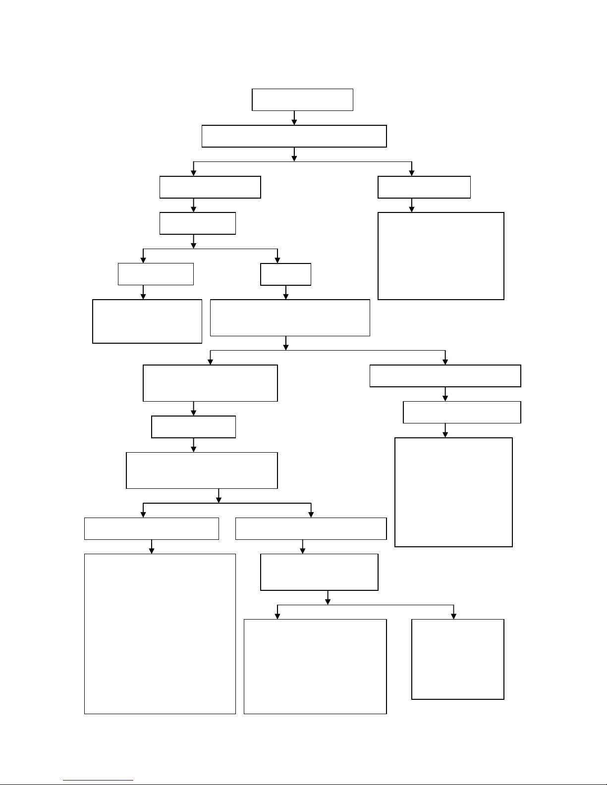
21
Remove the spark plug; check the
colors of spark plug insulators and
judge the proportion of mixed
combustible gas based on
abnormity
The spark plug insulators are black;
the exhaust muffler emits black
smoke or causes backfire if the
engine works at low speed; bad
acceleration property; instable idle
speed; flameout probability; it works
normally at high speed.
The spark plug insulators are brown
The spark plug insulators are
white; the engine may intermit
during acceleration; the carburetor
generates backfire; insufficient
power of engine
Mixed combustible gas
is too dense.
1. Check whether the air filter is
blocked.
2. Check whether the startup device for
carburetor (startup & enrichment
system) works normally.
3. Check whether the carburetor float is
too low.
Normal combustible gas mixture
Check whether the
cylinder outlet or the
exhaust muffler is blocked
due to accumulated carbon
fouling.
Check the lubrication
system
Mixed combustible
gas is diluted.
Lubrication system of
the two-stroke engine
1. Check whether the
fuel switch works
normally.
2. Check whether the
carburetor float is too
high.
3. Check whether the
measuring jets and
drill ways in the
carburetor are
blocked.
1. Check fuel level in the
crankcase.
2. Check whether fuel in the
crankcase has low viscosity or
is dirty.
3. Check whether the fuel filter
is blocked.
4. Check whether the fuel pump
works normally.
5. Check whether the lubricant
channel is blocked.
22
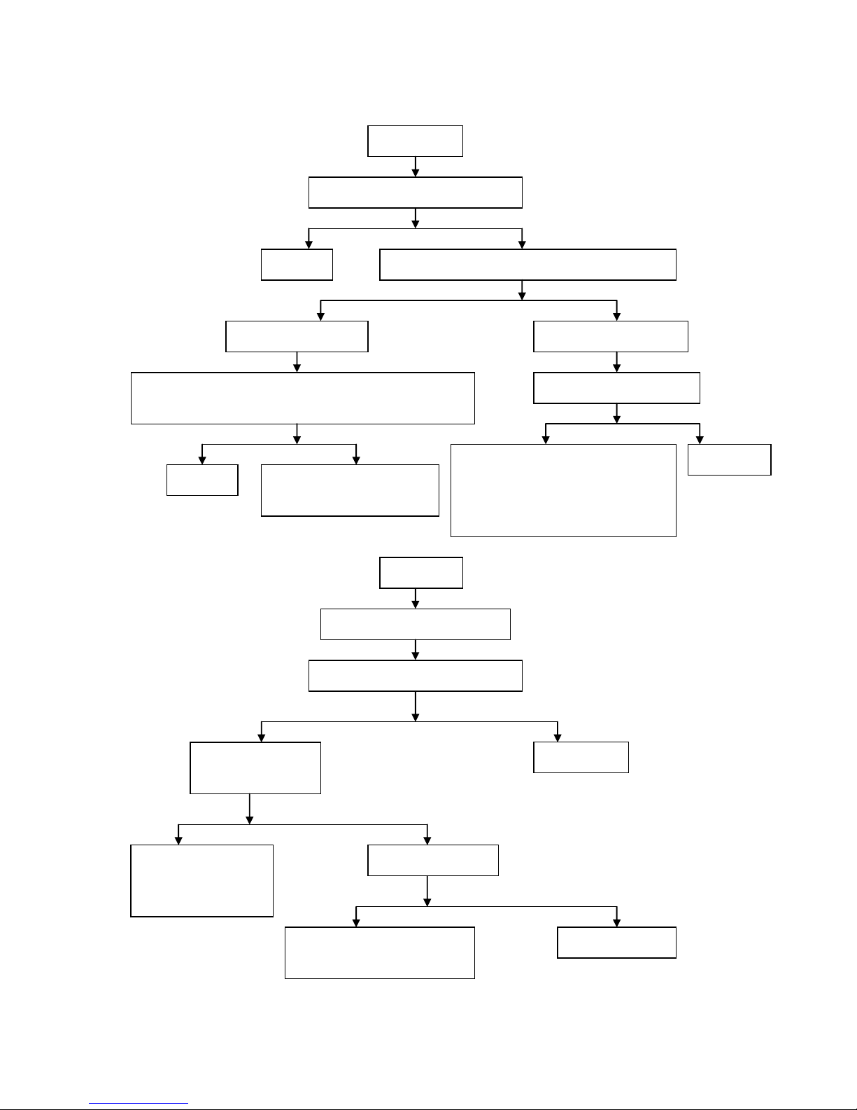
Y
N
Diagnosis on power shortage of engine
Power shortage of engine
Raise the main kickstand and suspend wheels; rotate
wheels with hands
Flexible rotating of wheels
Inflexible rotating of
wheels
Check tyre pressure
1. Check whether there is
braking drag.
2. Check whether wheel
bearing is excessively
abraded or damaged.
3. Check whether the middle
sleeve of hub is missed or
too short.
Low pressure
Normal
pressure
Check whether air leakage
occurs to tyre valve and
whether tyre is pierced or
broken
Remove the spark plug and block the
threaded hole with finger; press the startup
button or step on the kick-start lever
Touch with your fingers and you
can feel fierce air rushing out with
puffing sound.
Touch with your fingers and you can not
feel fierce air rushing out.
Normal compression
pressure of cylinder
Insufficient compression
pressure of cylinder
1. Check leakage on outer
connections of the engine.
2. Check whether the piston
ring is ruptured or seized in
the groove or whether it has
enough elasticity.
3. Check abrasion of the
piston ring and the cylinder.
Start the engine and slowly accelerate;
observe the rotation speed change of
engine.
The rotation speed of engine rises
as it slowly accelerates.
The rotation speed of engine does not
rise as it slowly accelerates.
1. 1. Check whether the clutch is slipping.
2. Check whether the driving belt is
excessively abraded.
3. Check whether the centrifugal roller of
driving pulley is excessively abraded.
4. Check whether the conical surface of
driving wheels and friction wheels is
excessively abraded or abraded to be
groove.
5. Check whether the conical surface of
driven wheels and moving driven wheels
is excessively abraded or abraded to be
groove.
6. Check whether the raceway on the inner
surface of friction wheels is excessively
abraded or pressed to be concave.
1. 1. Check whether the fuel supply
system works normally.
2. Check whether the carburetor, air
filter and exhaust muffler are
blocked.
3. Check whether the vacuum
diaphragm of plunger valve of
carburetor is cracked or broken.
1. Check whether CDI
ignition device is in
good condition
2. Check whether
flywheels and trigger
coil are loosened
Check whether ignition is
timely conducted with an
ignition timing lamp.
23
Y N Y N N Y Y N Y
N
Diagnosis on abnormal idle speed of engine
Abnormal idle speed of engine
High idle speed
No idle speed
Unstable idle speed
Check compression
pressure of cylinder
Check whether the carburetor
throttle is completely closed
with your hand.
Check whether ignition is
timely conducted with an
ignition timing lamp.
Insufficient
compression
Normal compression
pressure
1. Check leakage on
outer connections
of the engine.
2. Check whether the
piston ring is
ruptured or seized
in the groove or
whether it has
enough elasticity.
3. Check abrasion of
the piston ring and
the cylinder.
Adjust the idle speed
of carburetor.
Check
whether idle
jet is too big.
Check whether the
steel wire rope of
accelerator control
cable is flexible
when being pulled
and whether the
throttle valve
spring is too soft.
1. Check whether
CDI ignition
device is in good
condition
2. Check whether
flywheels and
trigger coil are
loosened
Idle speed after
adjustment
No idle speed
after
adjustment
The air adjusting
screws of the
carburetor or the
adjusting screws of
throttle valve are
improperly
Check whether the
carburetor idle jet, idle
fuel way and air path
are blocked.
Clean and
clear
Check whether carburetor float
is too high.
Adjust the float
height to
standard value.
1. Check whether the heat insulator of carburetor is
cracked.
2. Check whether the fixing nuts of carburetor are
loosened.
3. Check whether the negative pressure pipe of fuel
switch is broken.
4. Check whether air leakage occurs to reed valve.
Adjust the
electrode gap.
Check the proportion
of mixed combustible
gas.
Check
wheth
er the
electr
ode
gap of
spark
plug is
too
small.
24
Y
N
Y N Y N Y
N
Diagnosis on excessive fuel consumption of engine
Excessive fuel
consumption of engine
Check whether operation is correct
Raise the main kickstand and
rotate wheels with hands
1. Check whether the motorcycle
runs with overload or not at
economical speed or at low
gear.
2. Check whether petrol grade is
proper.
Inflexible rotating
of wheels
Flexible rotating of
wheels
1. Check whether
there is braking
drag.
2. Check whether
wheel bearing is
seriously abraded
or damaged.
3. Check whether
the middle sleeve
of hub is missed
or too short.
Check tyre
pressure
Low pressure
Normal
pressure
Inflate as required
Check whether oil leakage
occurs in fuel tank, fuel
switch, fuel pipe or carburetor.
Solve problems based on
actual situation
Check the proportion of
mixed combustible gas.
Normal combustible gas mixture
Mixed combustible
gas is too dense.
Mixed combustible
gas is diluted.
Check whether the idle
speed of engine is too high.
1. Check whether the air
filter is blocked.
2. Check whether the
carburetor float is too
low.
3. Check whether the main
measuring jet of
carburetor is too big.
1. Check whether the
carburetor is
blocked inside.
2. Check whether the
carburetor float is
too high.
Check and adjust the
carburetor.
Check whether ignition is
timely conducted with an
ignition timing lamp
Check whether the
driving belt of
clutch is slipping.
Check the ignition
system.
25
Y
N
Y
N
Y
N
N
Y
Y
N
Diagnosis on dense bluish white smoke from the exhaust muffler of the two-stroke engine
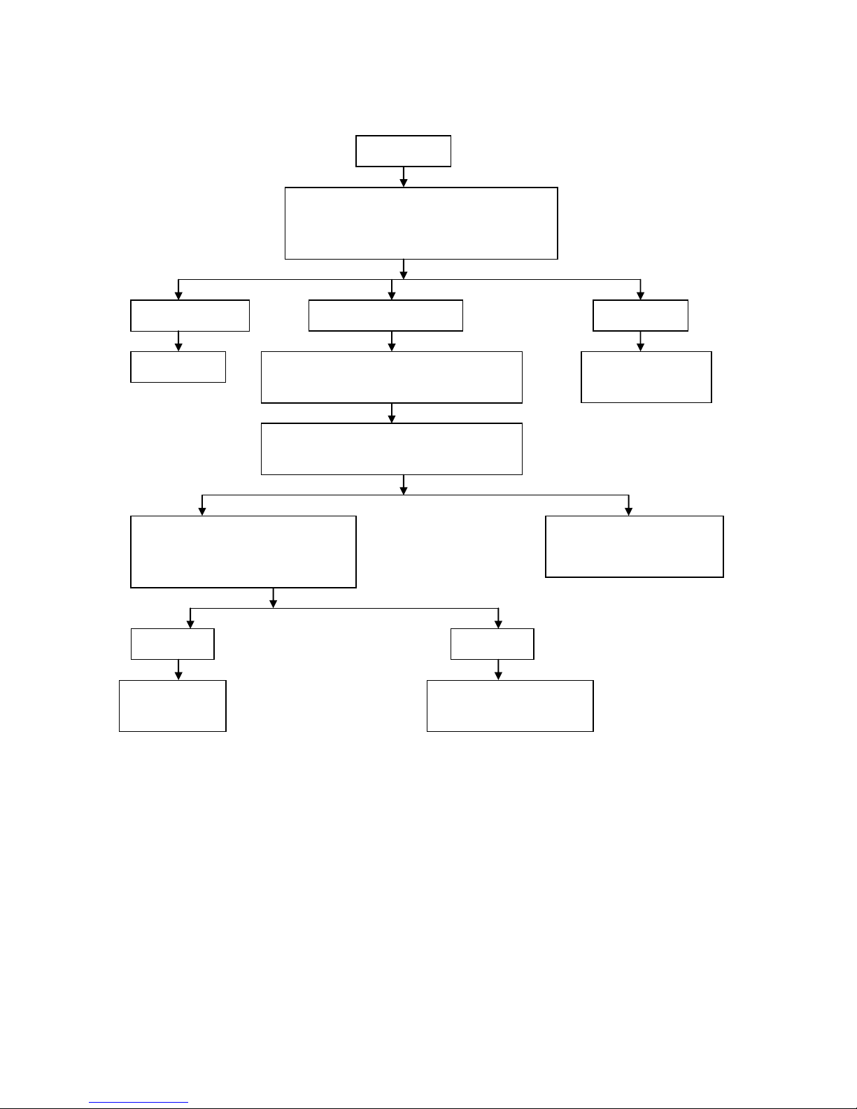
Diagnosis on difficulty in transmission shift
The exhaust muffler of the two-stroke engine emits dense bluish white smoke.
Check whether the fuel level in the crankcase exceeds the upper limit.
Excessive fuel filling into the crankcase.
Drain out the excessive part and make
sure the fuel level is not over the upper
limit.
1. Check whether the cylinder, the piston and the
piston ring are excessively abraded.
2. Check whether the piston ring has enough
elasticity or whether it is seized in the groove.
3. Check whether piston ring joint is staggered.
Difficulty in Transmission Shift
Start the engine and check whether the idle speed is too high.
Re-adjustment
Check whether it is coordinated when shifting
Check whether the clutch is completely released
Improve operation
Check whether the gearshift shaft is deformed or the
gearshift arm is deformed or excessively abrasive
1. Check whether the free stroke of the
clutch grip is between 10mm~20mm.
2. Check the balanced elasticity of clutch
spring.
3. Check whether the tooth-shaped groove
of the drive hub and the driven hub is
abraded to be jagged.
4. Check whether the driven disc of the
clutch is bent or deformed.
5. Check whether components of the clutch
lever are excessively abrasive.
Replace
1. Check whether the groove of the gearshift
cam is excessively abrasive or damaged.
2. Check whether the fork hole is
excessively abrasive.
3. Check whether the fork is deformed.
4. Check whether the fork shaft is deformed
or excessively abrasive.
Start up the engine and remove the dipstick when
it works at high speed. Check whether there is
smoke from the fuel filler.
26
N Y N Y N
Y
Y
N
Y N N
Y
Diagnosis on transmission gear skip shift
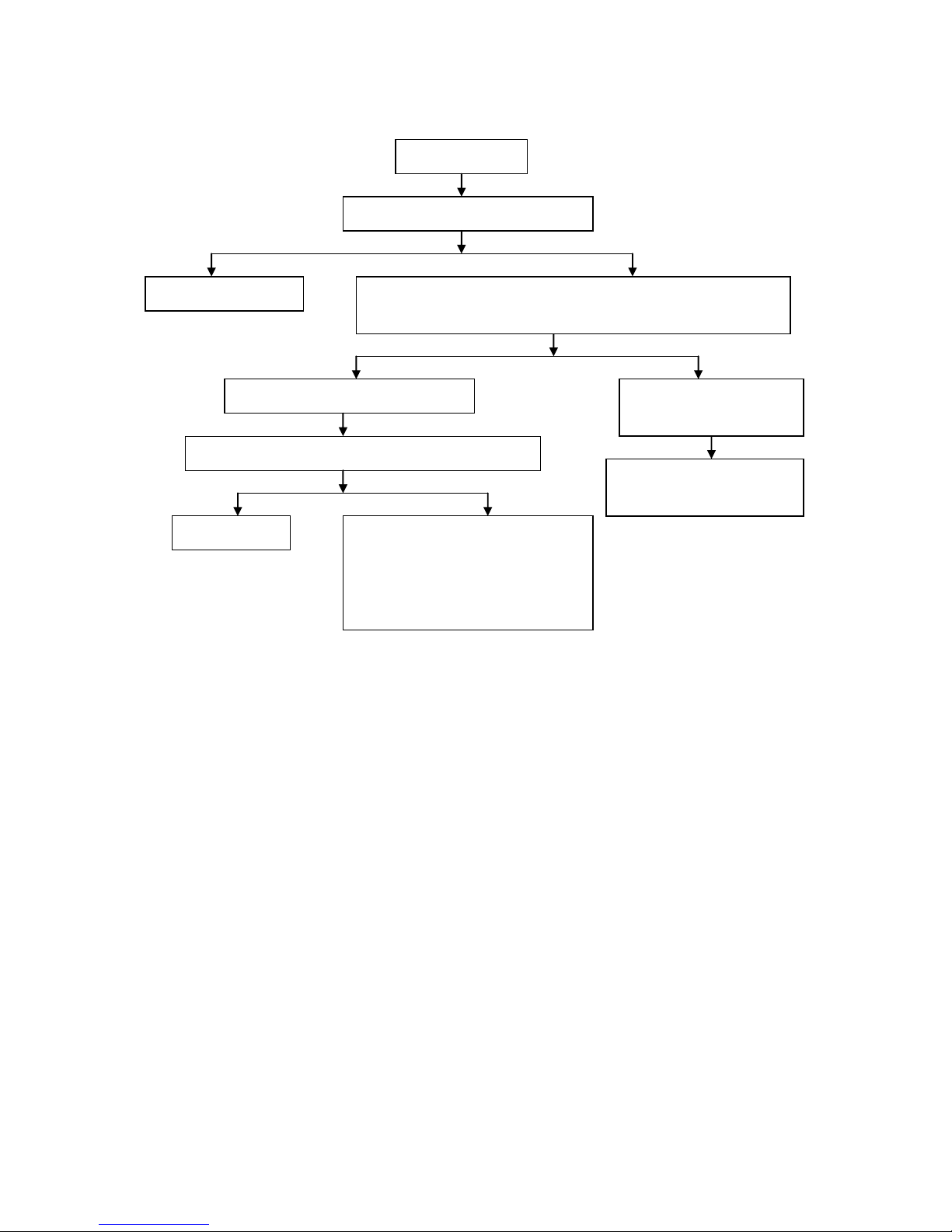
Diagnosis on clutch slipping
Clutch slipping
Automatic shoe-type centrifugal & dry
clutch is slipping.
Check whether the
shoe-type friction plate
is excessively abraded.
Replace the whole set of
clutch shoes
Clean and remove
oil stain
Check whether the contact
surface area between
shoe-type friction plate and
friction disc is beyond 70%.
Check whether the contact surface
between shoe-type friction plate and
friction disc is excessively abraded.
Repair or replace clutch
shoes
Check whether the shoe-type friction plate
is spotted with oil stain.
Transmission gear
skip shift
Check whether the positioning wheel spring
is ruptured or lacks elasticity.
Replacement
Disassemble crankcase and check whether the engagement
depth for each gear is in accordance with requirements.
Proper depth in engaging
Insufficient depth in engaging
Check whether the engaging end of the cam claw on the engaged gear
face is abraded to be conical or largely circular, and whether the groove
on the corresponding gear face is abraded to be trumpet-shaped.
Check whether the shift fork is
excessively abraded or deformed.
Replace gear
Check whether the spline teeth of
main shaft/countershaft and the
spline groove in the clash gear are
Replace shift
fork
1. Check whether shift fork hole and shift
shaft are abraded.
2. Check whether the gap between shift fork
pin/gearshift shaft and cam groove is too
big.
3. Check whether the installation of
27
N Y Y N N
Y
Diagnosis on malfunction of hydraulic disc brake
Diagnosis on malfunction of drum brake
Malfunction of hydraulic
disc brake
Check the level of brake fluid inside the
brake fluid reservoir.
The level of brake fluid is below the
lower limit of the reservoir.
The level of brake fluid is beyond the
lower limit of the reservoir.
Add brake fluid until
it is beyond the lower
limit; check whether
there is oil leakage in
brake caliper, brake
hose and hose joints.
Do you have "sponge"
feeling when operating
brake lever?
There is air left in
the oil passage of
brake system.
Check whether the abrasion of brake friction
plate reaches limit mark and whether the
brake disc is excessively abraded.
Replace brake
friction plate and
brake disc.
Malfunction of drum
brake
Check whether the free stroke of brake lever is within
10mm ~ 20mm or whether the free stroke of brake
pedal is within 20mm ~ 30mm.
Readjustment
Separate the brake arm and the steel wire rope of brake control cable; check the
brake arm with hands.
The brake arm works
flexibly but you can feel
resistance when griping
the lever.
The brake
arm works
inflexibly.
The indication arrow on the
brake cam points to or
beyond the sign “▽” on the
brake hub cover.
The indication arrow on the brake
cam does not align with the sign
“▽” on the brake hub cover.
The steel wire
rope of brake
control cable is
inflexible when
pulling.
1. Check whether the curved surface of
brake cam is excessively abraded.
2. Check whether the friction plate of brake
shoe is excessively abraded.
3. Check whether the inner diameter of
brake hub is excessively abraded.
1. Check whether the piston surface of master brake pump and the wall of oil tank
are excessively abraded or damaged.
2. Check whether the piston cup of master brake pump is damaged, cracked or aged.
3. Check whether the seal of brake caliper is damaged, cracked or aged.
4. Check whether the piston surface of brake caliper and the wall of oil tank are
excessively abraded or damaged.
The moving part
of brake cam is
rusty or blocked
by something.
1. Check whether the friction surface
of brake shoe is spotted with oil stain.
2. Check whether the contact surface
area of the friction plate of brake shoe
and the brake hub is less than 70%.
28
Y
N
Diagnosis on battery charging failure
Battery charging
failure
Resistance value lower
than standard value
Short circuit of
charging coil
Infinite resistance
value
Resistance value in accordance
with standard value
Open circuit of
charging coil or output
conductor.
Set the multimeter to DC voltage 0V~20V;
measure the voltage between the conductor
terminal (connector to battery) (normally red
wire or red/white wire) and the negative pole.
Bad connection or open circuit
between the electromagnetic motor
and the rectifier or the rectifier
regulator
No voltage
Voltage available
Open circuit between
the connector and the
battery.
Check whether the rectifier or the
rectifier regulator is broken down
with an ohm meter.
Remove the connector between the conductor bundle of
electromagnetic motor and the cable assembly; measure
the resistance between the output conductor terminals of
charging coil and check whether it is in accordance with
the standard.
Connect power to the connector between the
conductor bundle of electromagnetic motor and the
cable assembly; cut off the connector between the
Measure the resistance between the output conductor
terminals of charging coil of the connector and check
whether it is in accordance with the standard.
29
Y N Y
N
Diagnosis on insufficient battery charging
Insufficient battery
Check whether the brake lamp is always light.
Adjust or replace the brake
lamp switch.
Leakage current smaller than the required.
Leakage current larger than the
required (normally it shall be no
more than 1mA).
Check whether the charging coil of the magnetor is short-circuit.
Short circuit between the rectifier or
the rectifier regulator or the battery
and the ignition switch
Replace the charging
coil
1. Check whether the battery electrolyte is
enough.
2. Check whether the battery electrolyte is
diluted.
3. Check whether the battery electrode plates
are vulcanized or short-circuit.
Set the ignition switch to “OFF”; remove the negative cable from the battery;
connect the negative electrode of the ammeter to the battery negative terminal and
the positive electrode to the positive terminal; check current leakage.
30
Riding-style motorcycle
Motorcycle scooter
Y N Y
N
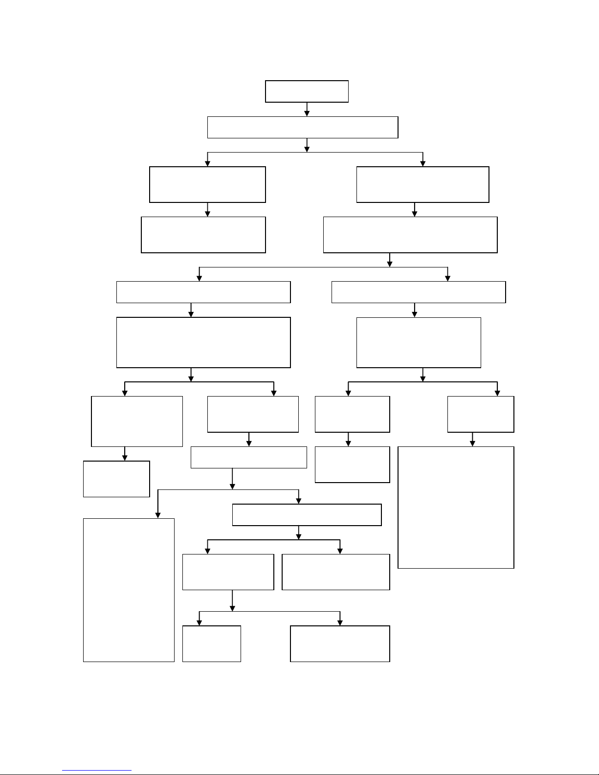
Diagnosis on starter motor failure in rotation
The electric horn does not make
sound or makes weak sound; the
steering lamp emits weak light.
The electric horn makes loud sound
and the steering lamp emits bright
light.
Battery power shortage or bad
contact of conductor joint
Grip the brake lever (motor scooter), or make
the transmission at neutral gear, or grip the
clutch lever; press the startup button.
Starter motor failure in
rotation
Turn the ignition switch; press the horn or turn the
steering lamp switch.
Press the startup button and there is no joint sound
from starter relay.
Press the startup button and there is joint sound
from starter relay.
Disassemble the connector of starter relay from
the cable assembly; use two lead wires to
connect the battery with two down-leads of the
starter relay coil.
Use screwdriver or large-diameter
lead wire to short-circuit the battery
terminal on the starter relay and the
starter motor terminal.
The starter relay works
normally after connection
The starter motor
works normally
after short circuit.
The starter motor does not
work after connection, and
there is no sound from
starter relay.
The starter motor
does not work after
short circuit.
Open circuit or
short circuit of
starter relay coil.
Check the inner circuit of the
electric starting control system
Contacts of starter
relay are burnt or
damaged.
Disassemble the starter motor and
check:
1. whether the carbon brush is
excessively abraded;
2. whether the carbon brush spring
is ruptured or lacks elasticity;
3. whether the armature
commutator is excessively
abraded;
4. whether open circuit or short
circuit occurs to the armature
coil.
1. Check whether the
contact of starting
button is in good
condition.
2. Check whether the
commutation diode is
damaged.
3. Check whether the
neutral gear switch
works normally.
4. Check whether open
circuit or short circuit
occurs to the inner
circuit of electric
starting control system.
Check whether the
contact of starting
button is bad.
Grip the brake lever and check whether the
brake lamp is light.
Bad contact inside the brake
lamp switch or open circuit of
its auxiliary circuit.
Repair or replace
starting button
Open circuit or short
circuit inside the electric
starting control system
 Loading...