

1
Matenance Manual
Model: Focus/Matrix
COPY RIGHT:
KEEWAY INTERNATIONAL DEVELOPMENT CO.,LTD.
FEB.2006

2
If you have any problems can not fnd the solution in this manual, please
fell free to contact with:
KEEWAY INTERNATIONAL DEVELOPMENT CO.,LTD
2000 SZENTENDRE U.8 KOZUZO. HUNGARY
TEL:0036-26-500005
FAX:0036-26-312034
EMAI: info@keewaymotor.com
Our engineer are very glad to give you the necessary assistance
and help.

3
Index
The service manual has been
specially prepared to provide all the
necessary information for the proper
maintenance and servicing of
FOCUS/MATRIX.
The FOCUS/MATRIX is a new type of
scooter that has many techinal features
such as:
V-belt drive automatic transmission
Forced air-cooling system
CDI ignition system
Electric starter system
The FOCUS/MATRIX fits the needs of
a wide variety of scooter user. Those who
will be servicing the scooter should
carefully review the manual before
performing any repair or services. Major
modifications and changes incorporated later
will be advised to QIANJIANG product
distributor in each market. Therefore, if
newest information is requested in the future,
please contact the local QIANJIANG
distributor.
The FOCUS/MATRIX scooters
distributed in your country mignt differ in
minor respects from the standard
specification and, if they do, it is because
some minor modifications had to be made to
comply with the statutory requirements of
your country.
前前前前

4
Index
Termly maintenance and repair 2
Engine 3
Fuell and lubricate system 4
Electrical system 5
Frame 6
Maintenance information 7
General principles 1

5

6
GENERAL PRINCIPLES
TYPE IDENTIFICATION 1-1
FUEL AND ENGINE OIL 1-1
BREAK-IN PROCEDURE 1-1
PRECAUTIONS AND GENERAL INSTRUCTIONS 1-2
MAINTENANCE TOOLS 1-3
SPECIFICATIONS 1-4
CONTENTS

7
1-1 GENERAL PRINCIPLES
TYPE IDENTIFICATION
①①①①
ENGINE NUMBER
ENGINE NUMBER① is carved on rear crankcase as
Shown in figure.
Both FRAME NUBER AND ENGINE NUMBER are
Designed specially for registering your scooter
and ordering spare parts.
FUEL AND ENGINE OIL
Be sure to use specified fuel and engine oil.
Some specifications are as follows:
FUEL
Unleaded, the minimum octane number is 90 or more.
ENGINE OIL
For QIANJIANG CCI SYSTEM, we recommend special engine oil, you can choose high quality two-stroke
engine oil (without being diluted) if without special oil.
GEAR OIL
Use high quality, all-purpose SAE90 engine oil for scooter.
BREAK-IN TIME
General requirements are as follows:
Limit break-in speed:
At the first 1000KMS(600 miles)mileage,play throttle less than 4/5 throttle;
After mileage exceeds 1000KMS(600 miles),play full throttle;
Don’t run engine too long during break-in time, and try to change throttle position.

8
1-2 GENERAL PRINCIPLES
PRECAUTIONS AND GENERAL INSTRUCTIONS
Correctly abide by the following items when disassembling and assembling scooter:
□ Don’t run engine indoors with little or no ventilation;
□ Be sure to replace new bushings, circlips, O-rings and cotter pins with new ones;
CAUTION
It is forbidden to use the circlip removed from shaft, only use new one;
Be very carefull to install new circlip for fear that the end hatch of circlip exceeds required sliding surface for
shaft;
After installing circlip, inspect whether it has been completely clipped into the groove.
□ Fix bigger diameter bolt first when tightening cylinder head or cylinder, and tighten to specified torque
gradually from inside to outside at diagonal order.
□ Use special tools for some special requrements;
□ Use original components and recommended engine oil;
□ Keep each other’s safety when several persons do;
□ Inspect looseness and operating state of components after reassembling them.;
□ Take high care of gasoline, which is explosive, and never use gasoline as lotion.
The words like warning, notice, note may turn out incessantly in the manual, which means:
WARNING——The personal safety of the rider may be involved. Disregarding the information could
result in injury to the rider.
CAUTION—These instructions point out special service procedures or precautions that must be followed to
avoid damaging the machine.
NOTE——it provides some special information, which keeps maintanance easier and important instructions
clearer..
REPLACEMENT COMPONENTS
Be sure to use genuine QIANJIANG components or their equivalent.. Genuine QIANJIANG components are
high quality parts which are designed specially for QIANJIANG vehicle.
CAUTION
Damage to the scooter may result from use of replacement components which are not
Equivalent in quality to genuine QIANJIANG parts, and it can lead to performance problems.

9
1-3 GENERAL PRINCIPLES
SPECIFICATIONS
DIMENSION AND NET WEIGHT
OVERALL LENGTH……1830mm
OVERALL LENGTH………695mm
OVERALL HEIGHT………1160 mm
WHEELBASE………………1295mm
NET WEIGHT………………92kg
CHASSIS
Front shock absorber……spring, without damp
Rear shock absorber……spring, oil damp
Turning angle … … … … … 48 º (toward the
left\toward the right)
Front wheel…………120/70-12
Rear wheel…………130/70-12
Front brake…………Discφ190
Rear brake…………Drumφ110
ENGINE
Type………two-stroke, forcible wind cooling
Intake system…………piston-reed valve
Cylinder QTY.…………1
Bore………………40.0mm
Stroke………………39.6mm
Discharge ………………49.8mL
Compression ratio……………6.9:1
Carburetor……………flat inhale stopper style
Air cleaner……………dry
Starting system…electricity start and kicking start
Lubricating system………pressure lubricating
ELECTRIC
Ignition mode…………CDI
Ignition timing…………150 at 1500RPM
Spark plug……………BP8HS
Storage battery…………YTX5L-BS
Generator……………AC magneto
Fuse……………8A
Headlight ……………12V—35/35W
Turning light……………12V/10W
Taillight ………………12V—21/5W
Meter light……………12V/1.7W
Oil level signal indicator light…12V/3W
Turning signal indicator light…12V/3W
CAPACITY
FUEL TANK……………5.2L
ENGINE OIL TANK……………1L
GEAR OIL……………0.1L
Transmission system
Clutch system .......dry auto acentric
Gearshift mechanism.....CVT stepless
Operating mode of gears shift mechanism...Automatic acentric
Stepless shift range.....0.86~2.64
*the above data may be modified without
any notification.

10
TERMLY MAINTENANCE AND REPAIR
CONTENT
Periodic maintenance and service schedule……………………… 2-
1
Maintenance and service procedures…………………………… 2-2
Storage battery………………………………………………… 2-2
Spark plug………………………………………………………… 2-3
Cylinder head nut and exhaust pipe bolt……………………… 2-3
Cylinder head and cylinder…………………………………………2-4
Fuel level line………………………………………………………2-4
Air cleaner……………………………………………………………2-5
Throttle cable…………………………………………………………2-5
Engine idle speed……………………………………………………2-5
Oil pump………………………………………………………………2-6
Gear oil………………………………………………………………2-7
Braking…………………………………………………………2-7
Tire …………………………………………………………………2-10
Steering………………………………………………………………2-10
Front shock absorber…………………………………………………2-11
Rear shock absorber…………………………………………………2-11
Vehicle bolts and nuts…………………………………………………2-11

11
Periodic maintenance and service schedule
The following table lists all required intervals for maintenance and service,following which, you are assred to
have your scooter perform in the best way.
Note
Do more frequent maintenance when often riding on bad road
Periodic maintenance table
Mile 600 4000 7500 11000 15000
Kilometer
1000 6000 12000 18000 24000
Interval
Months. 2 12 24 36 48
Storage battery I
I I I I
Cylinder head nut and
exhaust pipe bolt
T
T T T T
Cylinder head and
cylinder
—
C C C C
Spark plug —
R R R R
Air cleaner Clean every 3000KM(2000 miles)
Idle speed rpm
I I I I I
Throttle cable play
I I I I I
Oil pump
I I I I I
Gear oil I — I — I
I I I I
I
Fuel line
Replace every 4 years
Brake
I I I I I
I I I I I
Brake hose
Replace every 4 years
I I I I I
Brake fluid
Replace every 2 years
Steering
I I I I I
Front fork
I I I I I
Rear shock absorber
I I I I I
Tire
I I I I I
Vehicle body bot
andnut
T
T T T T
Note
I=inspect,clean,adjust,lubricate,or replace if necessary;
A=adjust; C=clean; R=replace; T=tighten

12
Maintenance and adjustment procedures
The section describes the servicing procedures for each item of the Periodic Maintenance requirements.
Storage battery
Inspect at initially 1000KM(600 miles,2 months),
andevery 6000KM(4000 miles,12 months)thereafter
□ Uncover seat, and then remove the battery box cap in the
Middle of helmet barrel.
□ Disconnect negative pole line end, positive end, and then remove battery;
□ Measure the voltage between the two ends of battery with
voltage gauge,charge if the voltage is below 12V

13
Cylinder head nuts and exhaust pipe bolts
Tighten at initially 1000 km(600 miles,2 moths),and
every 6000 km(4000 miles,12 months)
If cylinder head nuts are not tightened to the
specified torque, may result in leakage of
compressed fuel-air mixture and reduce output,
tighten the cylinder head nuts in the following
procedures::
1. Remove the frame lower covers.
2. Remove the cylinder head cover bolt.
3. Remove spark plug cap.
4. Tighten the nuts evenly one by one to the
their specified torque. Tighten the nuts in the
order indicated.
Tithtening torque::::
Cylinder head nut::::15-18N.m
Exhaust pipe bolt::::15-18N.m
Cylinder and cylinder head
Remove carbon every 6000 km( 4000
miles,12 months)
Carbon deposits in the combustion chamber and the
cylinder head will raise the compression ratio and may cause
preignition and overheating. Carbon deposited at the exhaust
port of the cylinder will prevent the flow of exhaust gases,
reducing the output. Remove carbon deposits periodically.

14
SPARK PLUG
Neglecting the spark plug maintenance eventually leads to
difficult starting and poor performance. If the spark plug is used for a
long time, the electrode gradually burns away and carbon builds up
along the inside part. In accordance with the periodic table, the plug
should be removed for inspection, cleaning and to reset the gap.
Carbon deposits on the spark plug will prevent good sparking
and cause misfiring. Clean the deposits off periodically.
If the center electrode is fairly worn down, the plug should be
replaced and the plug gap set to the specified gap using a
thickness gauge.
Thickness gauge
Spark plug gap:0.6-0.7 mm (0.024-0.028 inch)
Check the spark plug for burnt condition. If abnormal replace the spark
plug as indicated in the chart.
NGK TROCH REMARKS
BPR7HS E8RTC
If the standard plug is apt to get wet,
replace with the plug.
BPR8HS E7RTC Standard
BPR9HS E6RTC
If the standard plug is apt to
overheat, replace with the plug.
Tighten the spark plug to the specified torque.
Spark plug
Tightening torque:15-18N.m
NOTE:
To check the spark plug, first make sure that the fuel used is
unleaded gasoline, and if plug is either sooty with carbon or
burnt white, replace it.
Confirm the thread size and reach when replacing the plug.
FUEL LINE
Inspect at initially 1000 km (600 miles,2 months) and every
6000 km (4000 miles,12 months), replace every 4 years.

15
AIR CLEANER
Clean every 3000KM(2000 miles)
①①①①
If the air cleaner is clogged with dust, intake resistance will,
be increased with a resultant decrease in power output and an
increase in fuel consumption. Check and clean the element in the
following manner.
③③③③
Remove clamp ① and screw ②,take down air cleaner
Unscrew tapping screw③,remove air cleaner cap④。 ④ ②
Fill a washing pan of a proper size with
Non-flammable cleaning solvent. Immerse the air
Cleaner in the cleaning solvent and wash them clean.
Squeeze the cleaning solvent out of the washed element
By pressing it between the palms of both hands: do not twist
or wring the air cleaner filter core element or it will develop tears.,
Immerse cleaned filter core of air cleaner
in CCI or CCI SUPER oil, and squeeze the oil out of
the core,which may be slightly wet with oil.
Install air cleaner filter core in the reverse
order of removal.
CAUTION:
Before and during the cleaning operation, inspect the core for tears. A tore core must be
replaced
Be sure to position the filter core,so that no
incoming air will bypass it. remember, rapid wear
of piston rings and cylinder bore is ofter caused by
defective or poorly fitted filter core.
А Non-flammable cleaning solvent
БCCI or CCI SUPER oil
THROTTLE CABLE
Adjust at initially 1000KM(600 miles,2 months),
and every 6000 km(4000 miles,12 months)
Loosen locknut ①,and adjust throttle cable play by
turning adjuster ② in or out to obtain the
following cable play. After adjusting the calbe
play,tighten the locknut.
Cable play:0.5-1.0MM(0.02.-0.040 inch)
Engine idle speed
Adjust at initially 1000KM(600 miles,2 months)
and
every 6000 km(4000 miles,12 months)
thereafter.
② ①
Adjust the throttle cable play.
warm up the engine.
Note
NoteNote
Note::::
Warm up engine for 10 minutes.
Warm up engine for 10 minutes.Warm up engine for 10 minutes.
Warm up engine for 10 minutes.
16
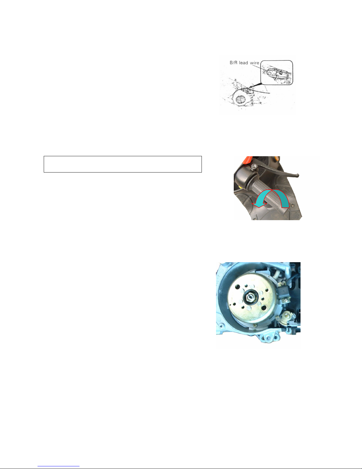
Connect an electric tachometer to the connecting protiion of the magneto lead wire as shown I nthe
illustration. Use the selector key “C’ position.
Tachometer
Adjust the throttle stop screw to obtain the idle r/min as follows:
Idle speed:1400±100r/min
Finally adjust the throttle cable play.
OIL PUMP
Inspect at initially 1000KM( 600 miles, 2 months)
andevery 6000 km(4000 miles,12 months)thereafter.
The engine oil is fed by the oil pump to the engine. The amount of oil fed to
it is regulated by engine speed and oil pump control lever which is controlled
by amount of throttle opening.
Check the oil pump in the following manner to confirm correct operation for
Throttle valve full opening position.
Turn the throttle grip full open.
Check whether the red mark ① on the oil pump control lever
Is aligned with the index mark ② when the throttle valve is positioned as above.
If the marks are not aligned, loosen lock nuts ③ and turn the adjuster ④ in or out to align the marks.
After align the marks, tighten the locknuts.
Caution:
Oil pump calbe adjustment must be done after throttle cable adjustment.
17
GEAR OIL
Inspect at initially 1000 km((((600 miles,,,,2 months))))and every
6000 km((((4000 miles,,,,12 months))))thereafter.
Inspect gear oil periodically as follows:
Remove the cover and hose
Remove the kicking starter lever
Remove clutch cover
Remove oil level bolt and inspect oil level, if oil level is below oil hole,
Add oil until oil flows from the level hole.
Tighten oil level bolt to the specified torque.
Tightening toque::::9-15N.m
((((0.9-1.5 kg-m ,,,,6.5-11.0 lb-ft))))
BRAKES
Inspect at initially 1000 km((((600 miles,,,,2 months)))) and
every 6000 km((((4000 miles,,,,12 months))))thereafter, replace
brake fluid every 2 years, replace brake hose every 4 years.
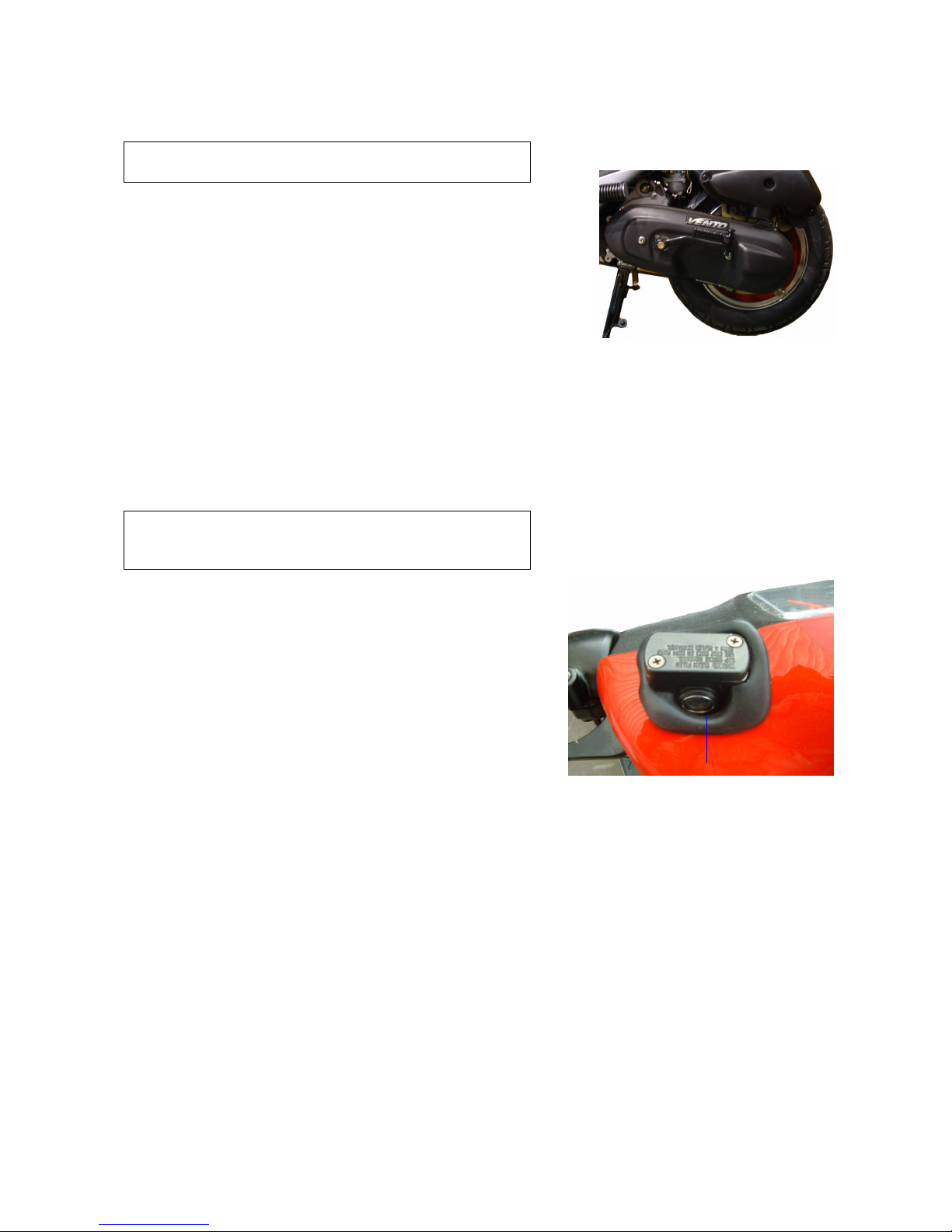
Front brake fluid level
Keep the scooter upright and place the handlebar staight.
Check brake fluid level by observing the lower limit line
on the brake fluid reservoir.
When the level is below the lower limit line, replenish with
Brake fluid that meets the following specification.
Specification and classification::::DOT4
QIANJIANG BRAKE FLUID
WARNING::::
The brake system of the scooter is filled with a glycol-based brake the lowest line
Fluid. Do not use or mix different types of fluid such as silicone-based and petroleum-based. Do not use any
brake fluid taken from old, used or unsealed containers. Never reuse the brake fluid left over from the
last servicing and stored for long periods.

18
WARNING::::
Brake fluid, if it leaks, will interfere with safe running and immediately discolor painted surfaces.
Check the brake hoses for cracks and hose joints for leakage before riding.
Brake pads
Wearing condition of brake pads can be checked by observing the limit
Line ① marked on the pad. When the wear exceeds the limit mark, replace
The pads with new ones.
Bleeding air from the brake fluid circuit
Air trapped in the fluid circuit acts like a cushion to absorb a large
proportion of the pressure developed by the master cylinder and thus
interferes with the full braking performance of the brake caliper. The
presence of air is indicated by “sponginess” of the brake lever and
also by lack of braking force. Considering the danger to which such
trapped air exposes the machine and rider, it is essential that, after
remounting the brake and restoring the brake system to the normal
condition, the brake fluid circuit be purged of air in the following manner:
Fill up the master cyliner reservoir to the upper end of the inspection
window. Replace the reservoir cap to prevent entry of dirt.
Attach a pipe to the caliper bleeder valve, and insert the free end of
The pipe into a receptacle.
□ Bleed air from the bleeder valve.
Squeeze and release the brake level several times in rapid succession. And squeeze the lever fully without
releasing it. loosen the bleeder valve by turning it a quarter of a turn so that the brake fluid runs into the
receptacles: the will remove the tension of the brake lever causing it to touch the handlebar grip. Then, close the
valve, pump and squeeze the lever, and open the valve. Repeat the process until the fluid flowing into the
receptacle no longer contains air bubbles.
19
NOTE::::when bleeding the brakign system, replenish the brake fluid reservoir if necessary.
Make sure that there is always some fluid visible in the reservoir.
Close the bleeder vavle, disconnect the pipe. Fill the reservoir with brake fluid to the upper end of the
inspection window.
BLEEDER VALVE
TIGHTENING TORQUE: 6-9N.m(0.6-0.9kg-m,4.5-6.5lb-ft)
CAUTION:
Handle brake fluid with care: the fluid reacts
chemically with paint, plastics, rubber materials, etc.
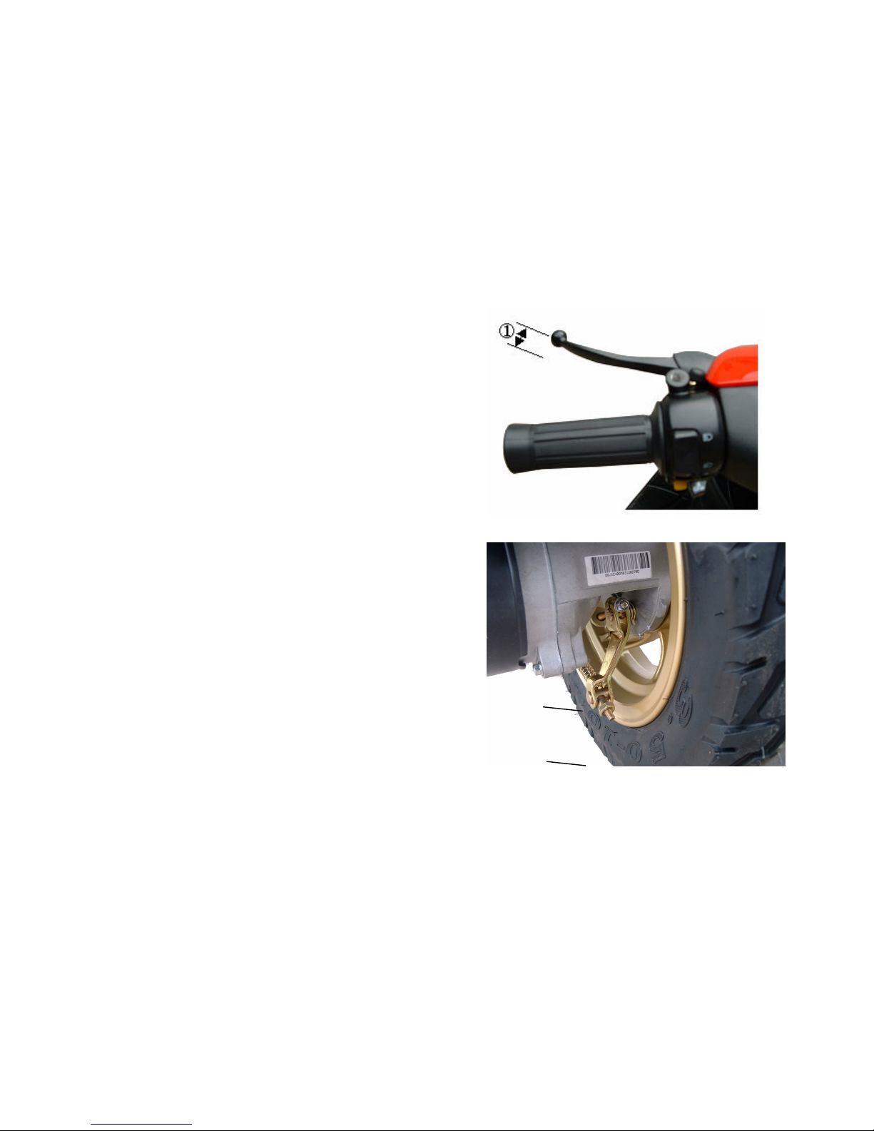
Rear brake
Turn adjusting nut ① so that the the play ② of
Brake lever is 15-25MM as shown in the illustration.
Brake shoe wear:
The vehicle is equipped with the brake lining limit
Indicator ③ on the rear brake.
Inspect brake lining limit as follows:
1. First check if the brake system is properly
Adjusted.
2. when operating the brake, check to see that
the tip of indicator ③ is within the range ④.
3. if the tip of indicator is beyond the range,
the brake shoe assembly should be raplaced with a ②
new set of shoe.
②
20
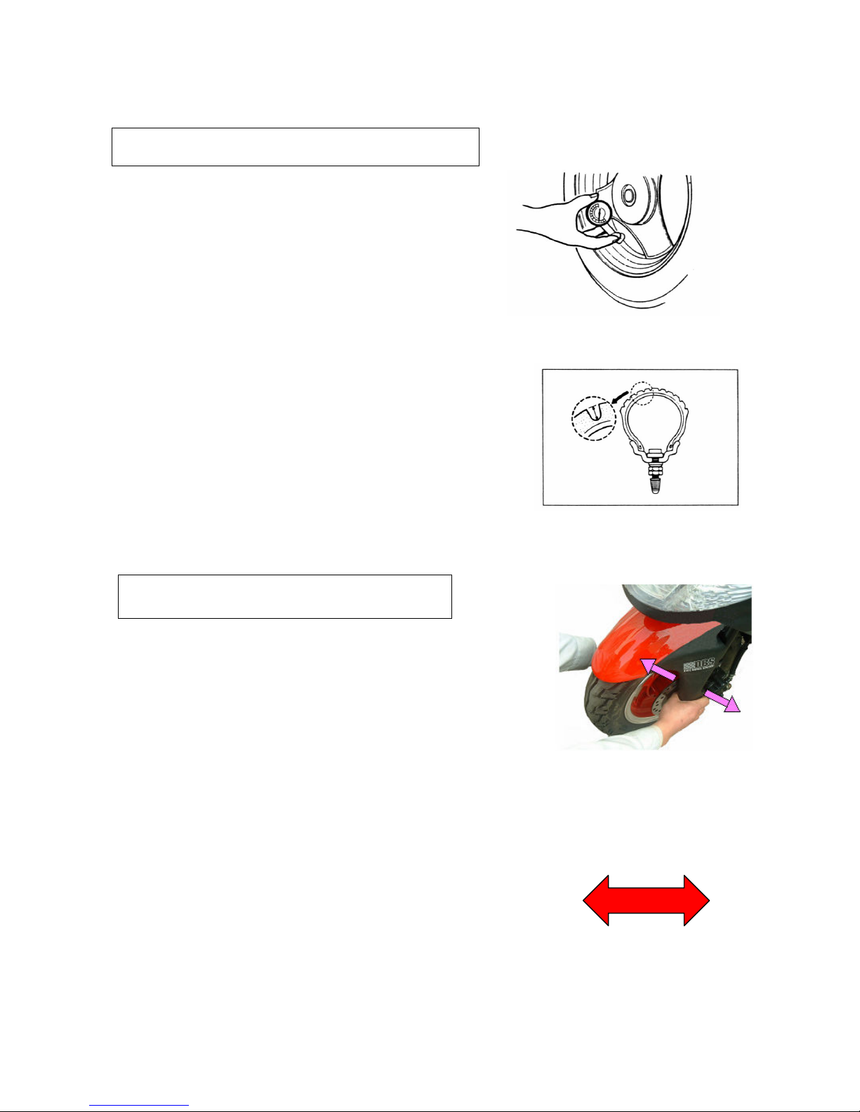
Tire
Inspect at initially 1000KM(600 miles,2 months) and every
6000KM(4000 miles,12 months)thereafter
Tire pressure:
If the pressure is too high, the scooter will tend to rede stiffly
and have poor traction. Conversely, if tire pressure is too low,
stability will be adversely affected. Thereafter, maintain the
correct tire pressure for good roadability and to prolong tire life.
CAUTION:
Caution:
The standard air pressure of tires is 175/196Kpa, The use of other
Than standard may cause handling instability. It is highly
recommended to use a QIANJIANG genuine tire.
Tire tread condition:
Operating the scooter with the excessively worn tires will decrease
riding stability and consequently invite dangerous situation. It is highly
recommended to replace the tire when the remaining depth of tire tread
reaches the following specification.
Front and rear:1.6MM(0.064IN)
Tire depth gauge
Steering
inspect at initially 1000KM(600 miles,2 months)
and every 6000KM thereafter.
Steering should be adjusted properly for smooth turning of handlebars
and safe running. Too stiff steering prevents smooth turning of handlebars
and too loose steering will cause poor stability.
Check that there is no play in the front fork assembly by supporting the
machine so that the front wheel is off the ground, with wheel staight ahead,
grasp lower shock absorber near the axle and pull forward. If play is
found, perform steering bearing adjustment.

21
Front shock absorber
Adjust at initially 1000KM(600 miles,2 months)
and
every 6000 km(4000 miles,12 months)thereafter.
Inspect the front shock absorber for oil leakage or other damage, and replace the defective parts, if necessary.
Rear shock absorber
Adjust at initially 1000KM(600 miles,2 months)and every
6000 km(4000 miles,12 months)thereafter.
Inspect front shock absorber for oil leakage and other damage, and replace the defective parts if necessary.
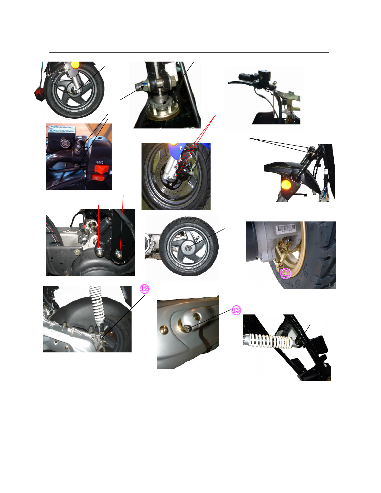
No. Item N•m Kg-m
1 Front axle nut 55-60 5.5-6
2 Handle tightenging nut 37-44 3.7-4.4
3 Steering sterm locknut 37-44 3.7-4.4
4 Disc brake caliper fixing bolt 22-29 2.2-2.9
5 Disc brake master cylinder hose fixing bolt 22-29 2.2-2.9
6 Disc brake fixing bolt 5-9 0.5-0.9
7 Front shock absorber fixing bolt 37-44 3.7-4.4
8 Engine pivot fixing nut 55-60 5.5-6
9 Engine bracket fixing nut 37-44 3.7-4.4
10 Rear wheel fixing nut 100-130 10-13
11 Rear brake rocker arm fixing bolt 5-9 0.5-0.9
12 Rear shock absorber under fixing bolt 22-29 2.2-2.9
13 Start pedal mounting screw 15-20 1.5-2
14 Rear shock absorber top fixing bolt 37-44 3.7-4.4
22
③③③③
①①①①
②②②②
④④④④
⑤⑤⑤⑤
⑥⑥⑥⑥
⑦⑦⑦⑦
⑧⑧⑧⑧
⑨⑨⑨⑨
⑩⑩⑩⑩
14

23
LUBRICATION
Proper lubrication is important for smooth operation and long life of each working part of the scooter. The
major lubrication points are indicated below:
NOTE:
1. Lubricate exposed parts which aare subject to ruse with engine oil.
2. Before lubricating each part, clean off any rusty spots and wipe off any grease, oil dirt of grime.
WARNING:Be careful not to apply too much grease to the rear brake camshaft, otherwise brake slippage will
result from the presence of grease in brake drum.
①steering stem bearing
②front wheel bearing
③engine bracket
④rear brake camshaft
⑤side stand
⑥rear brake shaft and rear brake calbe
⑦speedometer calbe and gear box
⑧main stand
Αlubrication
①A
②⑦A ④A
⑥A
⑤⑧A
③A

24
ENGINE
CONTENS
Engine components removal with the engine in place
Engine removal and remounting
Engine removal
Engine remounting
Engine disassembly
Engine components inspection and servicing
Bearings
Oil seals
crankshaft
automatic clutch inspection
cylinder head
cylinder
piston
reed valve
engine remounting
oil seals
bearings
bushings
crankshaft
crankcase
rear axle shaft
transmission
starter pinion and starter gear
Movable driven and clutch
Movable drive
Kicking starter
Piston
Oil pump and oil pump driven gear
Intake pipe
Magneto

25
Engine components removable with the engine in place
The parts listed below can be removed and reinstalled without removing the engine
from the frame.
Engine left side
Kicking starter lever
Clutch brake pad kit
Driver left face
V-belt
Driver belt right face
Electric starter gear
Super clutch
Driven face
Engine center
Carburetor
Intake pipe
Reed valve
Oil pump
Worm wheel
Cylinder head
Cylinder
Piston
engine right side
cooling fan
Magneto
Starter motor

26
ENGINE ASSY.
Remove the muffler
Remove cooling fan cover
Remove cylinder cover
Remove cooling fan
Remove magneto nut with special tools.
remove magneto rotor and half circle key
with special tools.
remove magneto stator and paper gasket
remove oil pump

27
Remove worm wheel and oil seal press board
remove cylinder head and
cylinder
Place a cloth stopper beneath the piston
and remove the circlip with a plier.
remove the piston pin and piston.
Remove the kick starter lever.
Remove side cover
Remove movable ratchet wheel and clip

28
Remove starting driven ratchet wheel by removing the nuts.
Rmove fan⑤ and V-belt⑥.
Disassemble the movable drive
face⑦.
Remove electric gear press board, electric
gear And super clutch
Remove starter motor
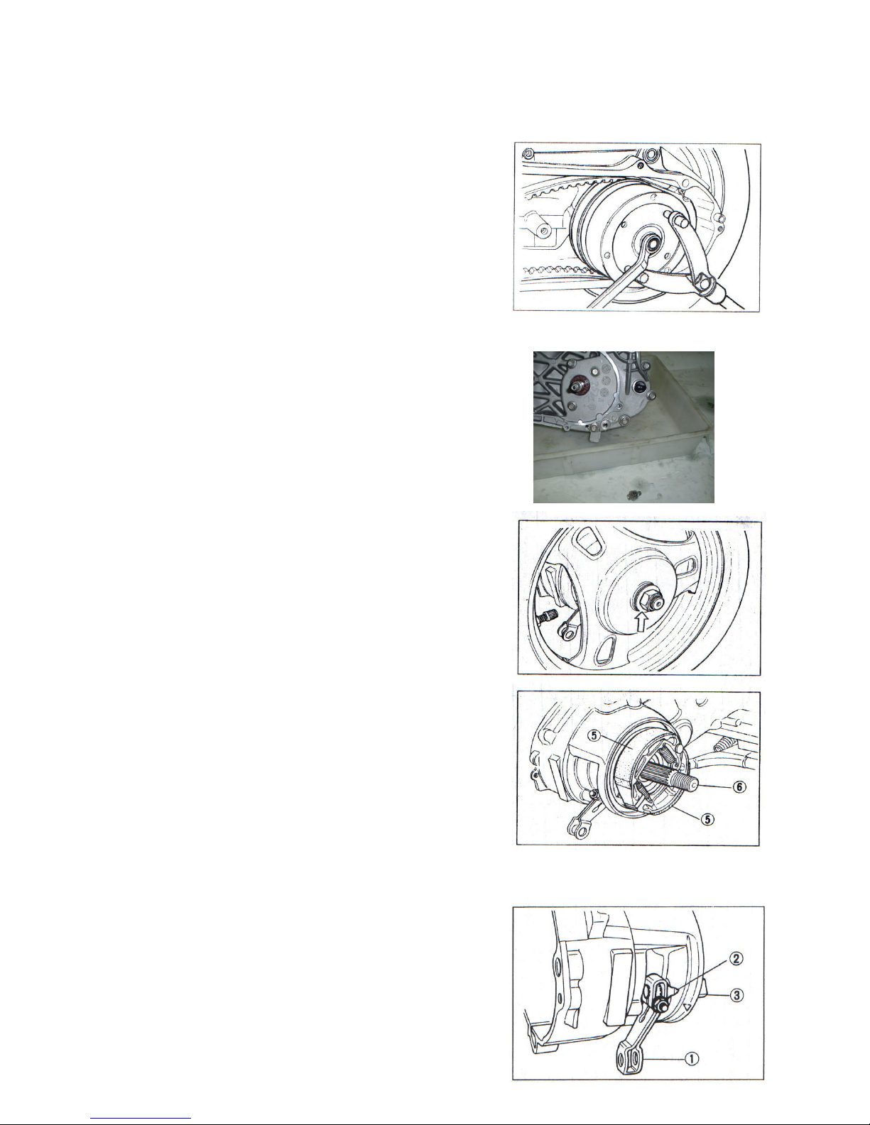
29
Remove the clutch housing with the
special tool.
drain gear oil
remove rear axle nut
remove rear wheel
remove brake shoe⑤ and rear axle⑥。
Remove the rear brake cam lever①,indicator
plate② and camshaft③.

30
remove spring④
remove cotter pin⑤ and shaft⑥
remove main stand⑦
remove gearcase cover
Remove paper gasket① and middle gear assy.②,
Remove output gear assy.③
remove carburetor
remove intake pipe
remove reed valve and paper gasket.
 Loading...