

KEEWAY ATV300 User Manual
1
CONTENTS
GENERAL INFORMATION
1.Information……………………………………………..…….…2222
2.Maintenance………………………………………
..
.…..6
3.EngineRemoval&Installation…………………………...…..13
ENGINE
4.LubricationSystem………...…………………………15
5.FuelSystem…………………………………………….19
6.CylinderHEAD&CylinderValve………...……….…..30
7.Cylinder&Piston……………………………………..46
8.V-Beltdrivingsystem…………………………………54
9.ACG&Startonewayclutch……………...…………..67
10.CoolingSystem……………...……………………..76
CHASSIS
11.Steering
Suspension…………
..
………................
84
12.Front
Wheel&
BrakeSystem……………
...
……….
90
13.RearWheel&BrakeSystem…………………….….95
14.ElectricalSystem…………………………………..97
15.TroubleShooting…………………………………..107
2
1. INFORMATION
1.1 SAFTY
1.2 NOTES
1.3 SPECIFICATION
1.4 SERIAL NUMBER
1.5 TORQUE VALUE
1.1 SAFETY
GASOLINE
Gasoline is extremely flammable and is explosive under certain condition. Do
not smoke or allow sparks or flames in your work area.
●
CARBON MONOXIDE
Never run the engine in a closed area. The exhaust contains poisonous carbon
monoxide gas that may cause loss of consciousness and lead to death.
●
BATTERY ELECTROLYTE
The battery electrolyte contains sulfuric acid. Protect your eyes, skin and
clothing. If you contact it, flush thoroughly with water and call a doctor if
electrolyte gets in your eyes.
●
HOT PARTS
Engine and exhaust pipe become very hot and remain hot for one hour after the
engine is run. Wear insulated gloves before handling these parts.
●
USED ENGINE/GEAR OIL
Used engine oil and gear oil may cause skin disease if repeatedly contact with
the skin for long periods.
Keep out of reach of children.
1.2 NOTES
All information, illustrations, directions and specifications included in this
publication are base on the latest product information available at the time of
approval for printing.
reserves the right to make changes at any time without notice and without
incurring any obligation whatever
.
No part of this publication may be reproduced without written permission.
1.3 SPECIFICATION ENGINE
Type
4 Stroke
,
Single Cylinder, Water cooled
Displacement
264
c.c.
Bore and Stroke
71 mm x 6
6.8 mm
3
SUSPENSION
Front
Double A
-
Arm & Adjustable Shocks
Rear
Double A
-
Arm & Adjustable Shocks
BRAKES
Front
Hydraulic Disc*2
Rear
Hydraulic Disc*
2
TIRES
Front
25x8-12
Rear
25x10-12
PRESSURE 【 psi ( kgf/cm2)
】
Front
8
(0.58)
Rear
9
(0.65)
COLORING
Specifications subject to change without notice.
Compression
10.5:1
O
utput
Power
14KW/6000rpm
Maximum Torque (Nm/rpm)
22.3 Nm / 5500
rpm
Carburetor
Vacuum film
Ignition
TC
I
Starting
El
ectric
Lubrication
15W-40
Transmission
Au
tomatic (C.V.T. V
-
belt
+
Shafts
)
CHASSIS
Overall Length
2170mm
Overall Width
1200
mm
Overall Height
1210mm
Wheel base
1275mm
Ground Clearance
260
mm
Dry Weight
330
kg
Fuel Tank Capacity
13L
4
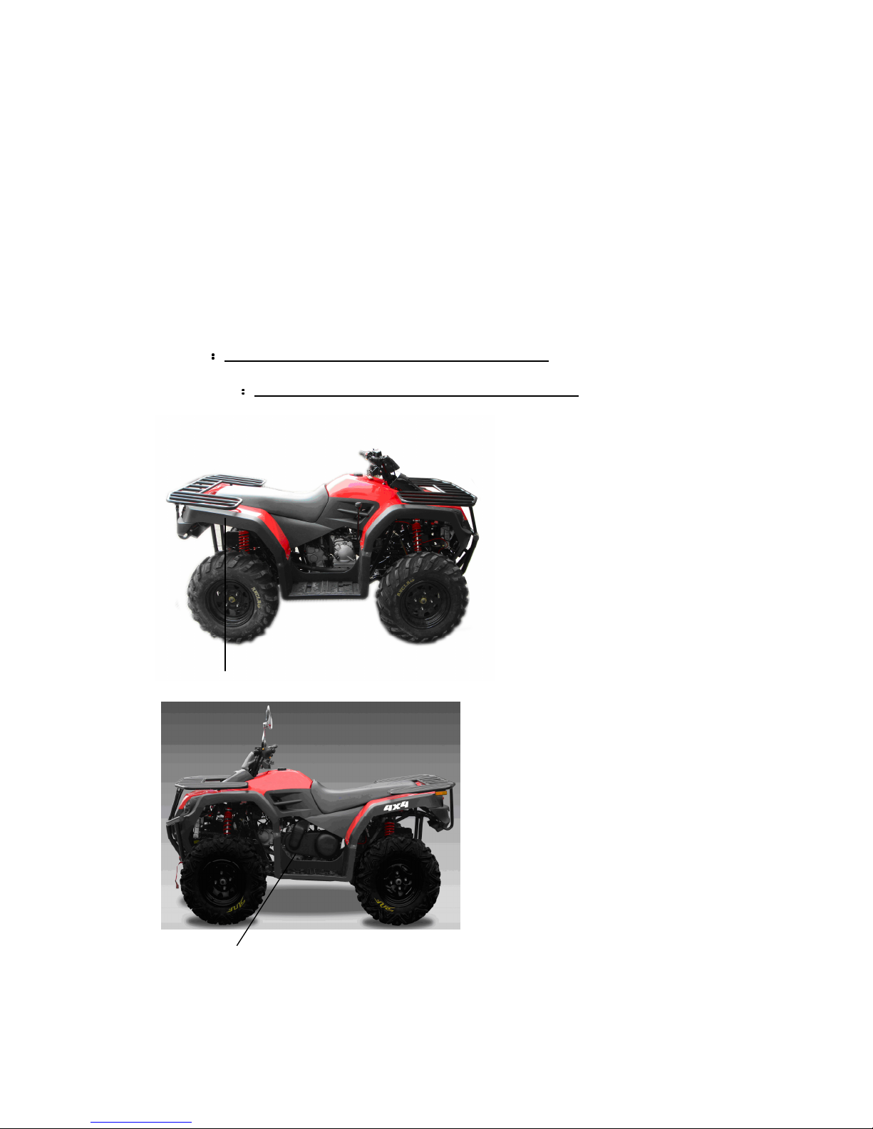
1.4 SERIAL NUMBER
Vehicle Identification Number (VIN) and Engine No. are used for registration. When you
order parts or need special service, these numbers can help you receive the best service from
our Authorized Dealers.
We recommend copying your vehicle identification date in your operation and
maintenance manual and on a sheet that you should keep in a safe place, separately from
the vehicle.
The VIN No. A is stamped on the central frame tube, to view the number ,remove the
inspection cap at the central of the leg guard; the ENGINE No. B is engraved on the left side
of crankcase, A is VIN plate jointed on the right side of tail frame.
VIN NO.
::::
ENGINE NO.
::::
A(VIN NO.)
B
(ENGINE NO.)
5
1.5 TORQUE VALUES
FRAME
●
Handlebar upper holder bolt
24 N.m (17.7 lbf.ft)
●
Throttle housing cover screw
4 N.m (2.9 lbf.ft)
●
Steering shaft nut
50 N.m (36.9
lbf.ft)
●
Steering shaft holder bolt
33 N.m (24 lbf.ft)
●
Wheel rim bolt
18 N.m (13.3 lbf.ft)
●
Tie rod lock nut
35 N.m (25.8 lbf.ft)
●
King pin nut
40 N.m (29 lbf.ft)
●
Handlebar lower holder nut
40 N.m (29.5 lbf.ft)
●
Front wheel bolt
24 N.m
(17.7 lbf.ft)
●
Front axle castle nut
40-60 N.m (30
-
45 lbf.ft)
●
Front brake arm nut
4 N.m (3.0 lbf.ft)
●
Rear brake arm nut
7 N.m (5.2 lbf.ft)
●
Rear axle castle nut
40-60 N.m (30
-
45 lbf.ft)
●
Rear wheel bolt
24 N.m (17.7 lbf.ft)
●
Exhaust muffler mounting bolt
30 N.m (22.1 lbf.ft)
●
Engine hanger bolt
30 N.m ( 22 lbf.ft)
●
Rear axle holder bolt
90 N.m (65 lbf.ft)
●
Swing arm pivot nut
90 N.m (65 lbf.ft)
●
Rear shock absorber mounting nut
45 N.m (33 lbf.ft)
STANDARD
●
5 mm bolt and nut
5 N.m (3.5 lbf.ft)
●
6 mm bolt and nut
10 N.m (7.2 lbf.ft)
●
8 mm bolt and nut
22 N.m (16 lbf.ft)
●
10 mm bolt and nut
35 N.m (25 lbf.ft)
●
12 mm bolt and nut
55 N.m (40 lbf.ft)
ENGINE
●
Cylinder head nut
28 N.m (20.7 lbf.ft)
●
Spark plug
12 N.m (8.9 lbf.ft)
●
Cylinder head bolt
20 N.m (14.8 lbf.ft)
●
Alternator bolt
8 N.m (5.9 lbf.ft)
6
2. MAINTENANCE
2.1 MAINT
ENANCE DATA
2.8 IDLE SPEED
2.2 MAINTENANCE SCHEDULE
2.3 FUEL TUBLE
2.9
BRAKE SYSTEM
2.4 THROTTLE OPERATION
2.10
WHEELS AND TIRES
2.5 THROTTLE CABLE AJUSTMENT
2.11
STEERING SYSTEM
2.6 AIR CLEANER
2.12
TOE
-
IN
2.7 SPARK PLUG
2.1 MAINTENANCE DATA
SPECIFICATION
SPARK PLUG
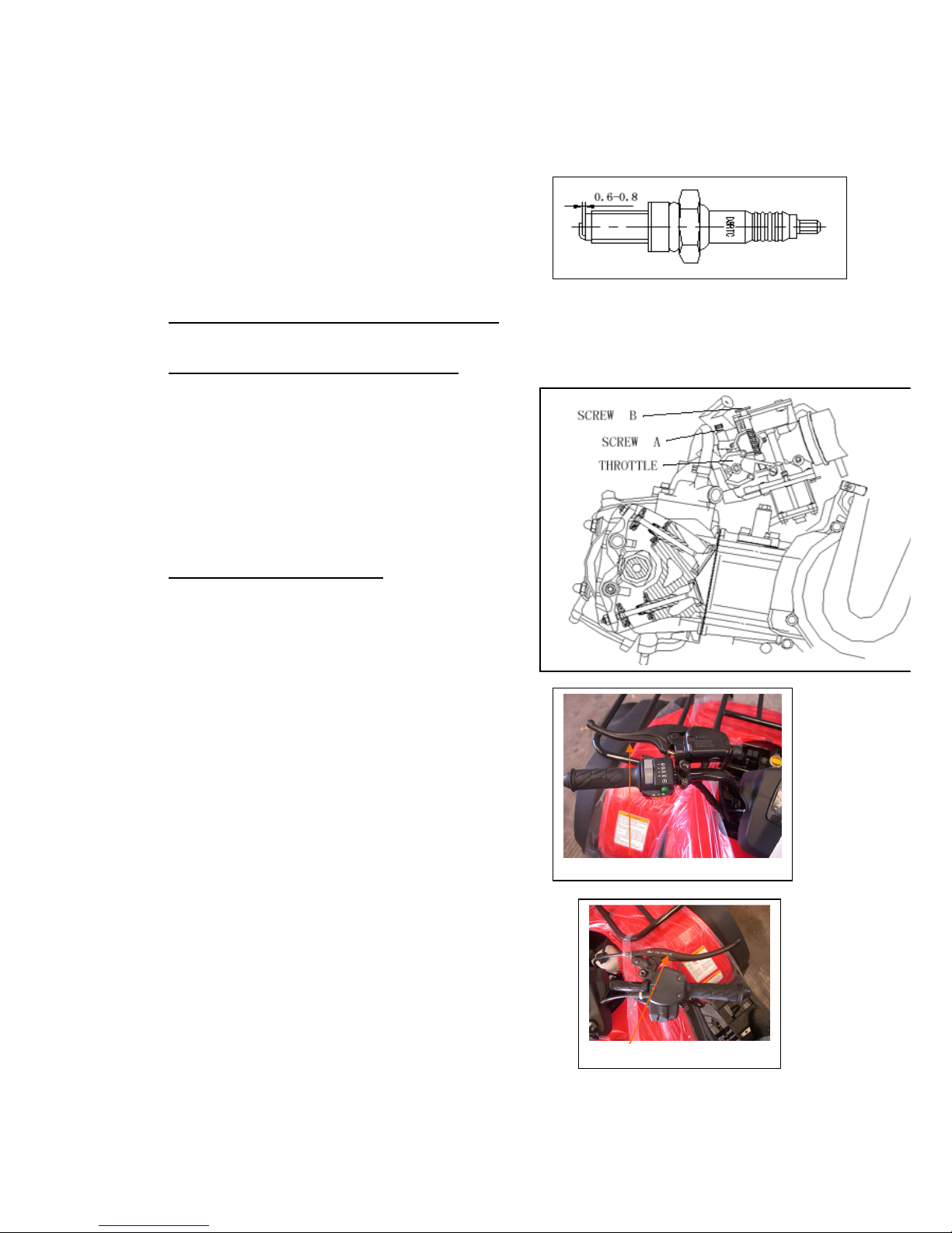
SPARK PLUG GAP
0.6-0.8 mm
RECOMMENDED SPARK PLUGS
NGK
DR8EA
THROTTLE LEVER FREE PLAY
2-5 mm
IDLE SPEED
1500±100 rpm
BRAKE LEVER FREE PLAY
15-25 mm
TORQUE VALUES
SPARK PLUG
12-19 N.m
TIE-ROD LOCK NUT
35-43 N.m
ENGINE OIL
1.2
Liter (1.
0
Liter for change)
GEAR LUBRICATION OIL
750cc (650cc for change)
7
2.2 MAINTENANCE SCHEDULE
To keep the performance good, the motorcycle should be checked and maintained at certain
interval. The meanings of capital in following table are:
I: Inspection, including check, clean, lubricate, refuel, repair or replacing if necessary.
A: Adjusting C: Cleaning R: Replacing T: Tightening
Maintenance
period
Items
Odometer (km)
里程数
里程数里程数
里程数
300
1000
2000
3000
4000
5000
6000
7000
8000
9000
10000
11000
12000
Everyday
check
before
riding
Crankcaselube
R R R R R R R I
Lube filter
C C C C
Air filter
Clean filter every 2000~3000 km. change it when necessary
Spark pl
ug Initial 1000km and Clean every 3000~4000km change it when necessary
Valve gap
A A A A
Cam chain
A A A A
Carburetor
I I,C
I,C
I,C
Gas filter
R
Brake system
I I I I I I I I I I I I I
Driving chain
I I I
Fasteners
T T T
Coolent
A A A A A I
Gearbox oil
I R R R
Battery
I
* When the mileage is over the highest on the table, please perform according to the period set
on the table
* Driving on dust place, it is recommended to clean it frequently.
8
2.3 FUEL TUBE
Inspect the fuel lines for deterioration,
damaging or leakage and replace if necessary.
2.4 THROTTLE OPERATION
Inspect for smooth throttle lever full opening and
automatic full closing in all steering positions.
Inspect if there is no deterioration, damage or kink
in the throttle cable, replace it if necessary.
Check the throttle lever, free play is 2
————
5 mm at the
tip of the throttle lever.
Disconnect the throttle cable at the upper end.
Lubricate the cable with commercially lubricant to
prevent premature wear.
2.5 THROTTLE CABLE ADJUSTMENT
Slide the rubber cap of the adjuster off the throttle
Housing, loosen the lock nut and adjust the free play
of the throttle lever by turning the adjuster on
the throttle housing. Inspect the free play of the
throttle lever.
2.6 AIR CLEANER
Please remove the four hooks, and then disassemble
two screws inside the air cleaner case.
Pull out the air filter element from the air cleaner case.
Washing the element in non-flammable solvent, squeeze
out the solvent thoroughly.
Let it dry.
Soak the filter element in gear oil and then squeeze
out the excess oil.
Install the every
component
into air cleaner in the reverse
order of removal.
Note: for more detail please check chapter 5-10
Throttle
9
2.7 SPARK PLUG
This spark plug is located at the front of the engine.
Disconnect the spark plug cap and unscrew
the spark plug.
Check the condition of spark plug electrodes wear.
Change a new spark plug if the electrodes and
insulator tip appear unusually fouled or burned.
Discard the spark plug if there is apparent wear
if the insulator is cracked or chipped.
The spark plug gap shall keep in 0.6-0.8mm
With the sealing washer attached, thread the
spark plug in by hand to prevent crosses threading.
Tighten the spark plug with 12-19 N.m
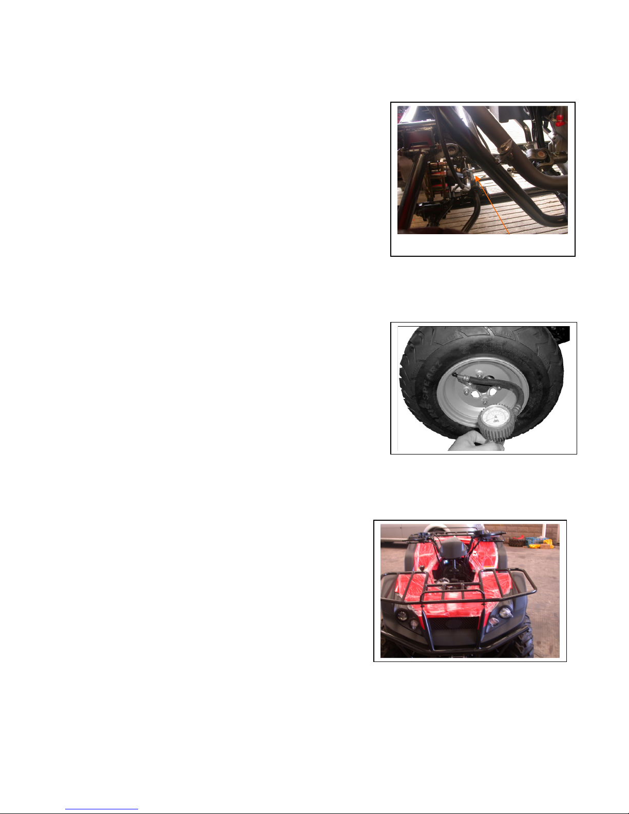
2.8 IDLE SPEED
Connect an engine speed meter.
Warm up the engine, 10 minutes are enough.
Turn the idle-speed adjust screw B on the carburetor
to obtain the idle speed. “Turn in” (clockwise) will
get higher speed. “Turn out” (counter clockwise) will
get lower speed.
IDLE SPEED: 1500±100 rpm
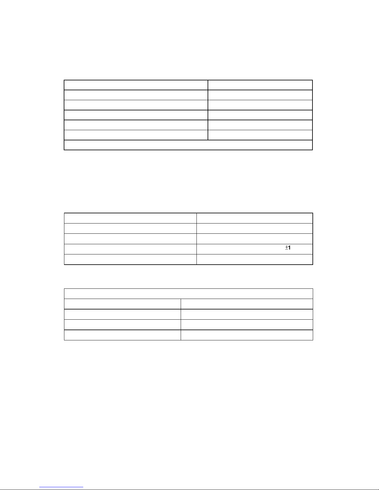
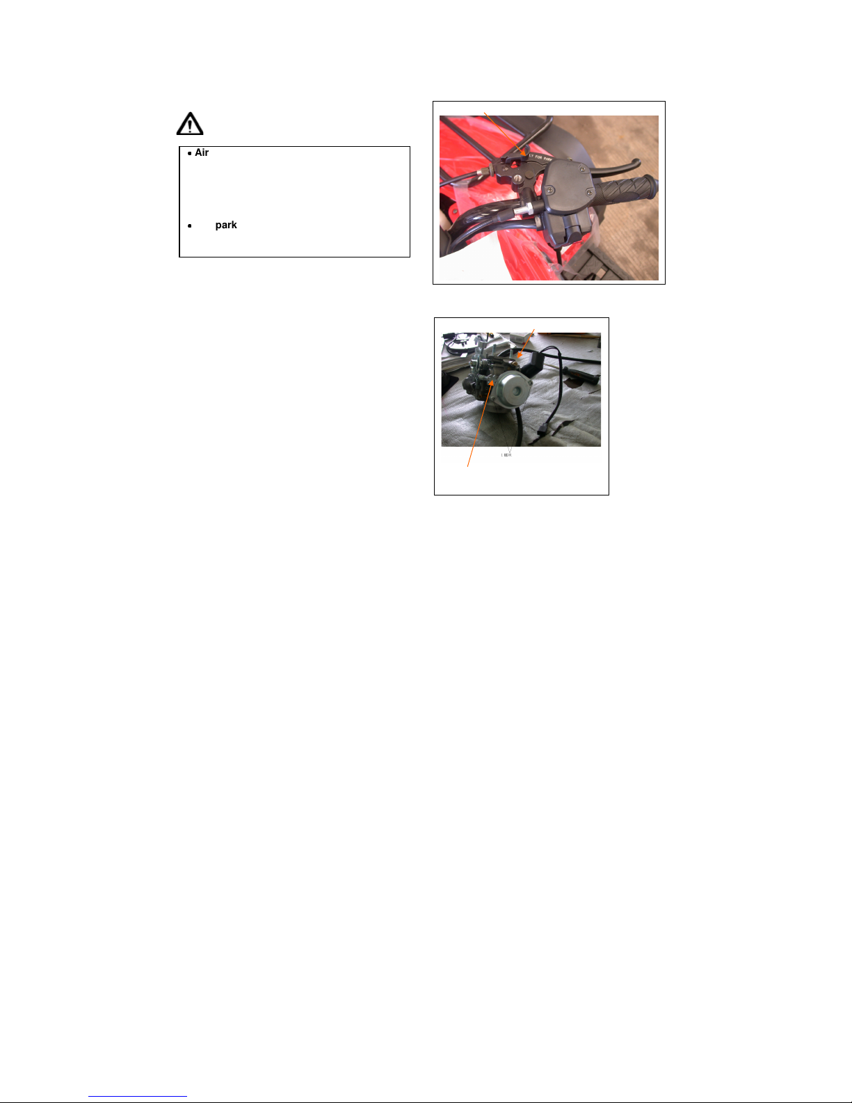
2.9 BRAKE SYSTEM
Inspect the front brake lever and cable for excessive
play or other damage.
Replace or repair if necessary.
Measure the free play of the brake lever at the end of the
brake lever.
The standard of free play is 5-15 mm.
The parking brake is shown on the picture. The position
of parking Off is on the left side. Turn parking brake to
right side is parking on
Brake handle
Parking Brake
10
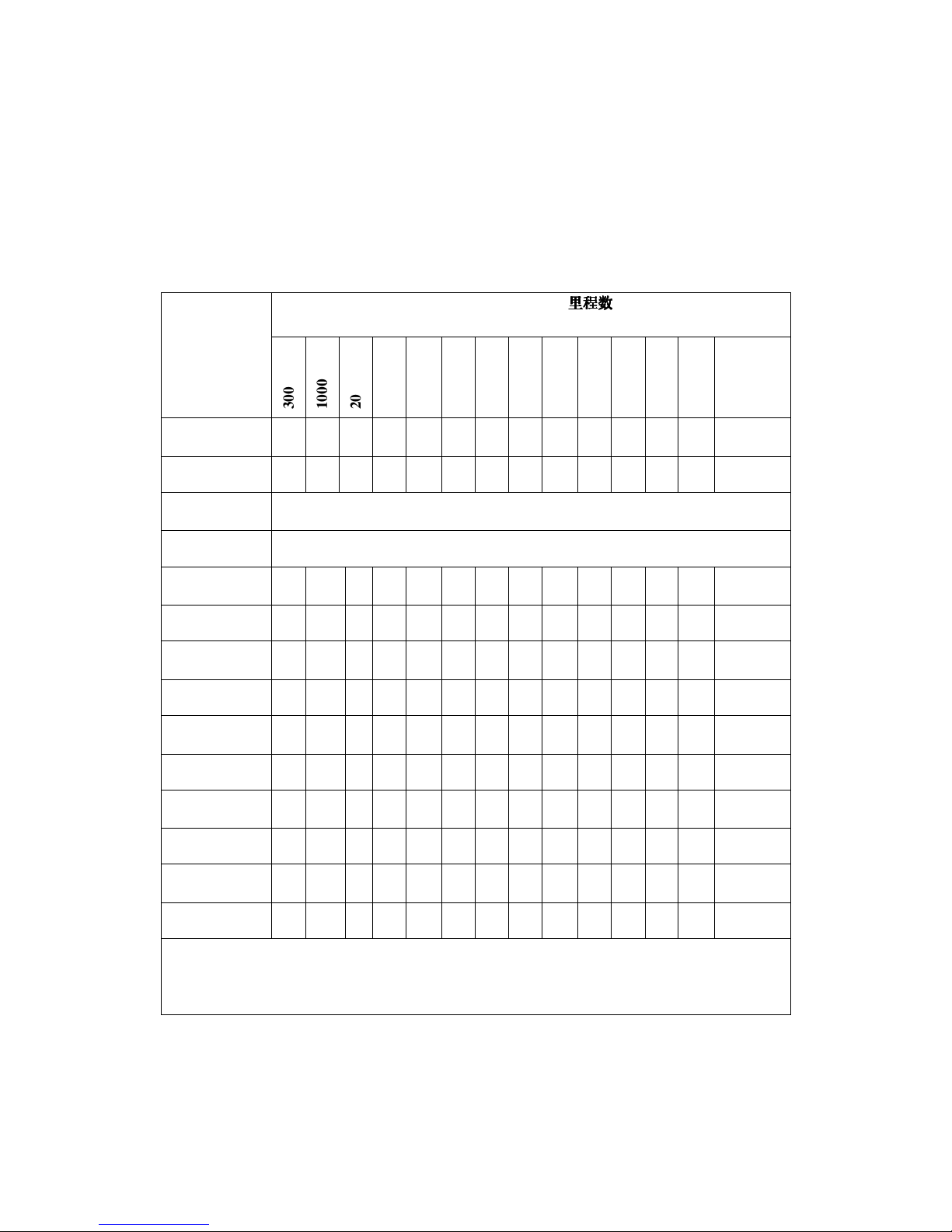
Inspect the rear brake lever and cable for excessive
play or other damage.
Replace or repair if necessary.
Measure the free play of the rear brake lever at the
end of the lever.
The standard is 5-15 mm.
The second method to adjust brake level is under the
driver seat and rear brake component.
Because the brake system is different, ones need to adjust it
to reach a proper brake level.
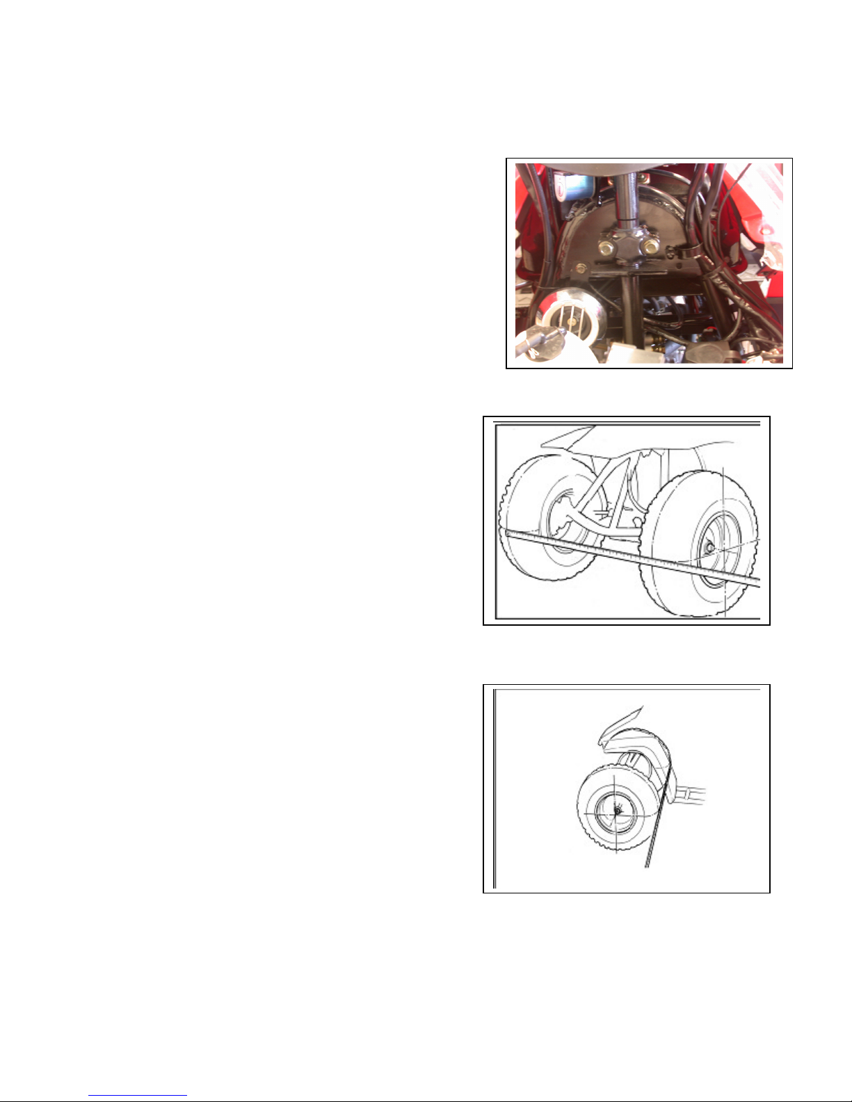
2.10 WHEELS AND TIRES
Inspect the tire surfaces for cuts, nails or other
sharp objects.
Check the each tire surface at cold tire condition.
*The standard of tire pressure is 8(0,6до1,0)
psi ( kgf/cm2)
2.11 STEERING SYSTEM
Check the free play of the steering shaft with the front
wheels, turned straight ahead.
When there is excessive play, inspect the tie-rod,
kingpin bushing and ball joint.
Parking BRAKE Adjustabie nut
11
STEERING SHAFT HOLDER BUSHING
Remove the front fender first.
Remove the steering shaft holder and check the
steering shaft bushing for wears or damage.
If the bushing is worn or damaged, please change a new
one.
Grease the steering shaft bushing and install the parts
in the reverse order of removal.
Torque: steering shaft holder bolt: 33 N.m (24 lbf.ft)
2.12 TOE-IN
Keep the vehicle on level ground and the front
wheels facing straight ahead.
Mark the centers of the tires to indicate the axle
center height.
Measure the distance between the marks.
Carefully to move the vehicle back, let the wheels
turn 180 degree, so the marks on the tires are aligned
with the axle center height.
Measure the distance between the marks.
Calculate the difference in the front and rear
measurements.
Toe-in: 5±10mm
12
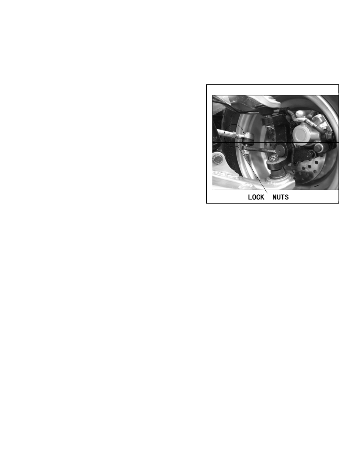
If the toe-in is out of standard, adjust it by changing
the length of the tie-rods equally by turning the tie-rod
while holding the ball joint.
Tighten the lock nuts.
Torque: 35-43 N.m
13
3. ENGINE REMOVE AND INSTALLATION
3.1 REPAIR CONDITION
3.3 ENGINE INST
ALLATION
3.2 ENGINE REMOVAL
3.1 ENGINE SHALL BE REMOVED IN THE CONDITIONS OF NECESSARY
REPAIRMENT OR ADJUSTMENT TO THE TRANSMISSION AND
COMBUSTION SYSTEM ONLY
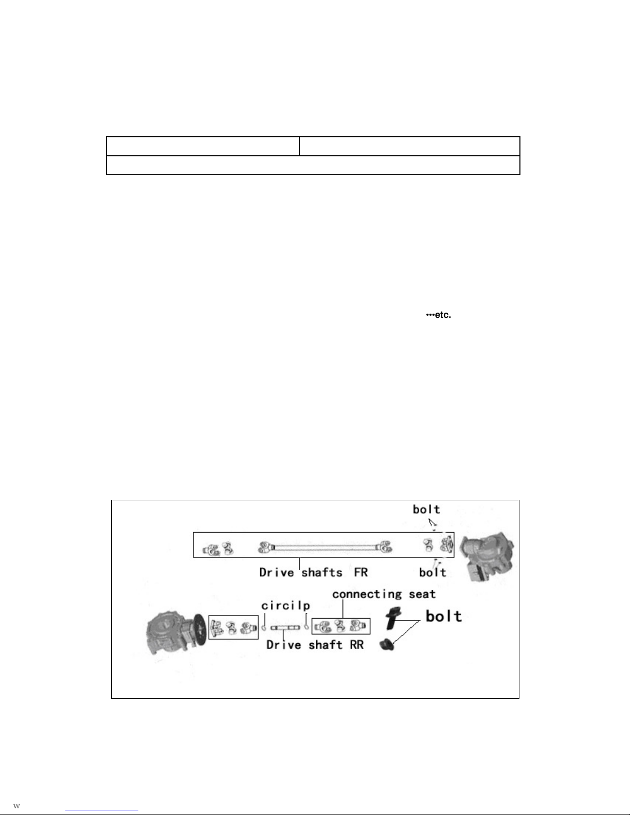
3.2 ENGINE REMOVAL
Before removing engine, you need to remove all of components such as seat, front and
back fender, fuel tube, exhaust pipe, carburetor cable and drive shafts
…………
etc. You can then
see three hanger bolts which have screwed on engine.
Loosen these three hanger bolts. You have succeeded to remove this engine.
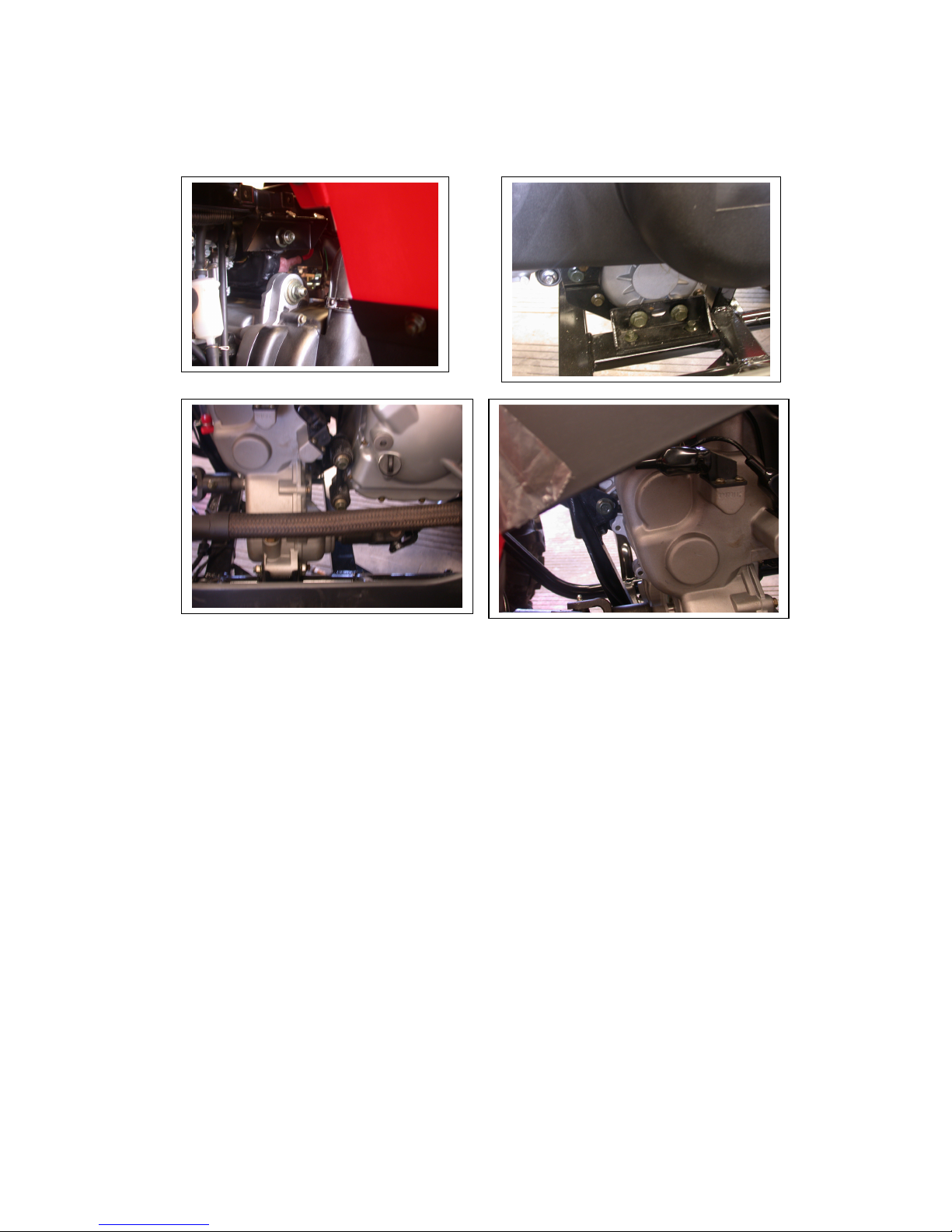
There are some pictures to describe main step of removing engine.
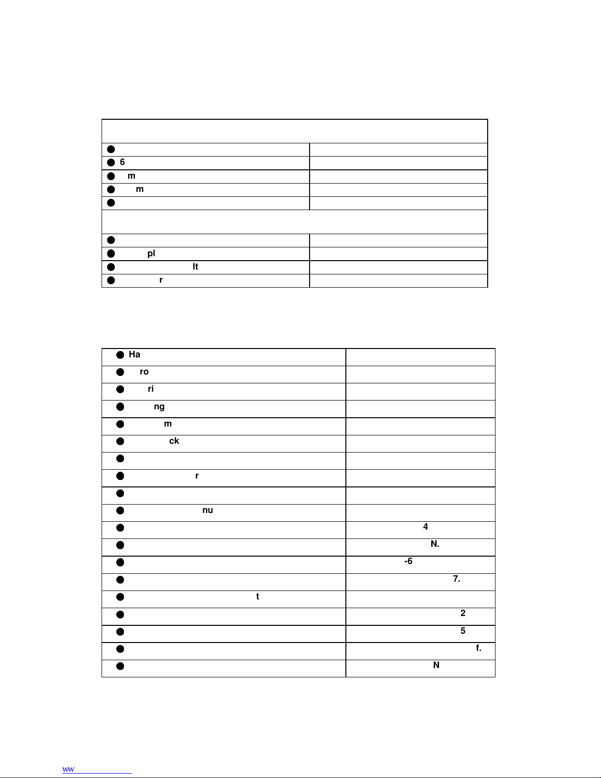
Disconnect the wire connectors. There are three
connectors for carburetor auto-choke, starter motor
and generator respectively.
Remove the drive Shafts.
14
3.3 ENGINE INSTALLATION
The Engine installation is essentially in the reverse order of removal.
The torque of engine hanger bolt is 30 N.m
Route the wires and cable in reverse order properly.
15
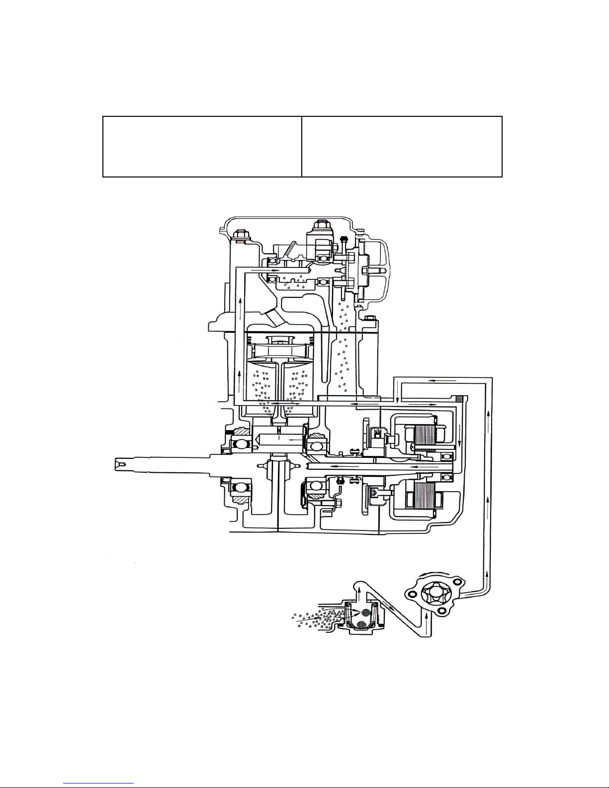
4. LUBRICATION SYSTEM
4-1 Mechanism Diagram
4-2 Precautions in Operation
4-3 Troubleshooting
4-4 Engine Oil
4-5 Engine Oil Strainer Clean
4-6 Gear Oil
4-1 Mechanism Diagram
16
4-2 Precautions in Operation
General Information:
This chapter contains maintenance operation
for the engine oil pump and gear oil replacement.
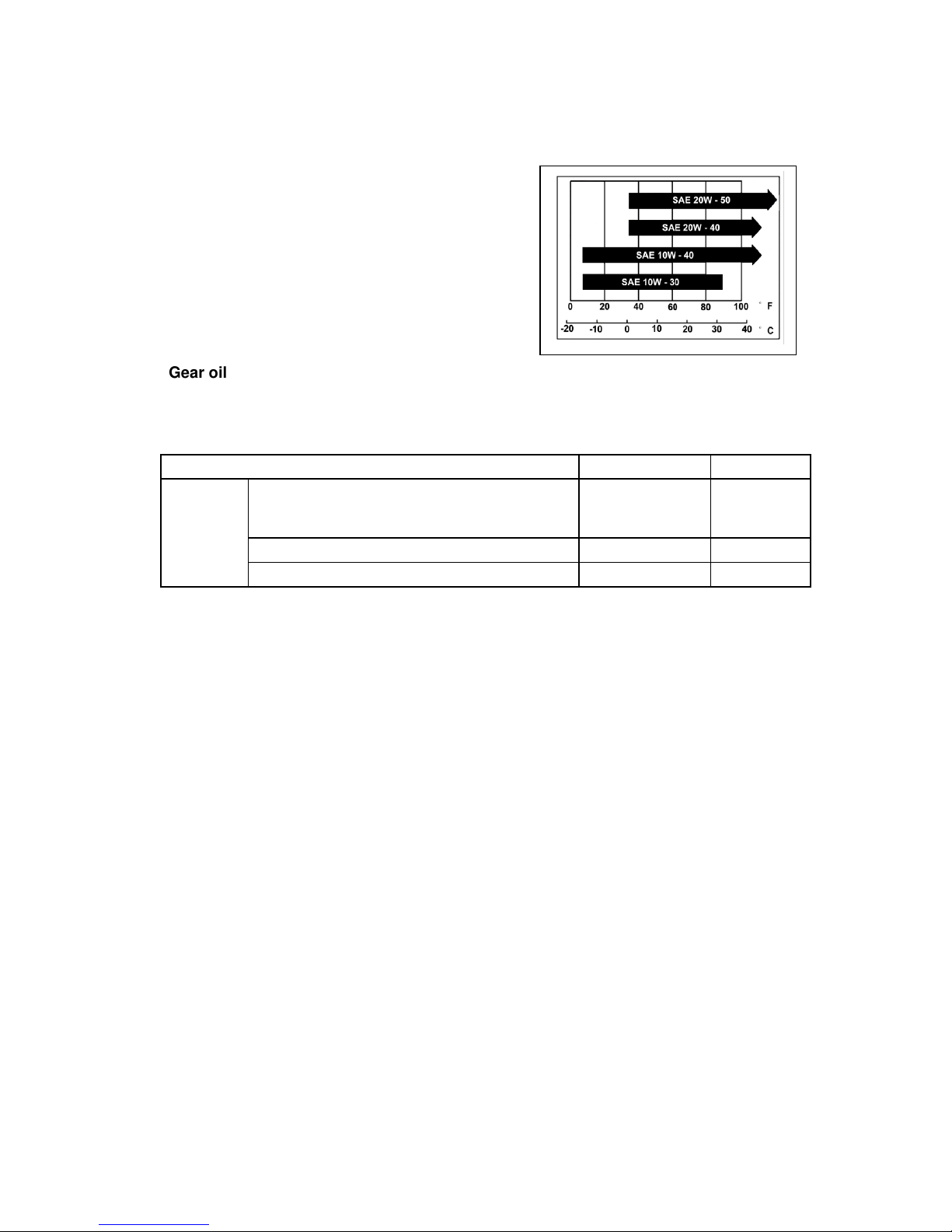
Specifications
Engine oil quantity Disassembly: 1200 c.c.
Change: 1000c.c.
Oil viscosity SAE 10W-40 (Recommended King serial oils)
單位
單位單位
單位
:mm
Gear oil Disassembly: 750c.c.
Change: 650c.c.
Gear oil viscosity SAE 10w- 40
(Recommended SYM Hypoid gear oils)
Torque value
Torque value oil strainer cap 1.5~3.0kgf-m
Engine oil drain bolt 1.9~2.5kgf-m
Gear oil drain bolt 1.0~1.5kgf-m
Gear oil join bolt 1.0~1.5kgf-m
Oil pump connection bolt 0.8~1.2kgf-m
4-3 Troubleshooting
Low engine oil level Low oil pressure
Oil leaking Low engine oil level
Valve guide or seat worn out Cylinder head gasket damage
Piston ring worn out Piston ring worn out
Dirty oil
No oil change in periodical
Cylinder head gasket damage
Piston ring worn out
Items
Standard (mm)
Limit (mm)
Oil pump
Inner rotor clearance
0.15
0.20
Clearance between outer rotor and body
0.15~0.20
0.25
Clearance between rotor side and body
0.04~0.09
0.12
17
4-4 Engine Oil
Turn off engine, and park the ATV in flat
surface with main stand.
Check oil level with oil dipstick.
So not screw the dipstick into engine as
checking.
If oil level is nearly low level, fill out
recommended oil to upper level.
Oil Change
Caution
Drain oil as engine warmed up so that makes sure
oil can be drained smoothly and completely.
Place an oil pan under the ATV, and remove oil
drain bolt.
After drained, make sure washer can be re-used.
Install oil drain bolt.
Torque value:1.9~2.5kgf-m
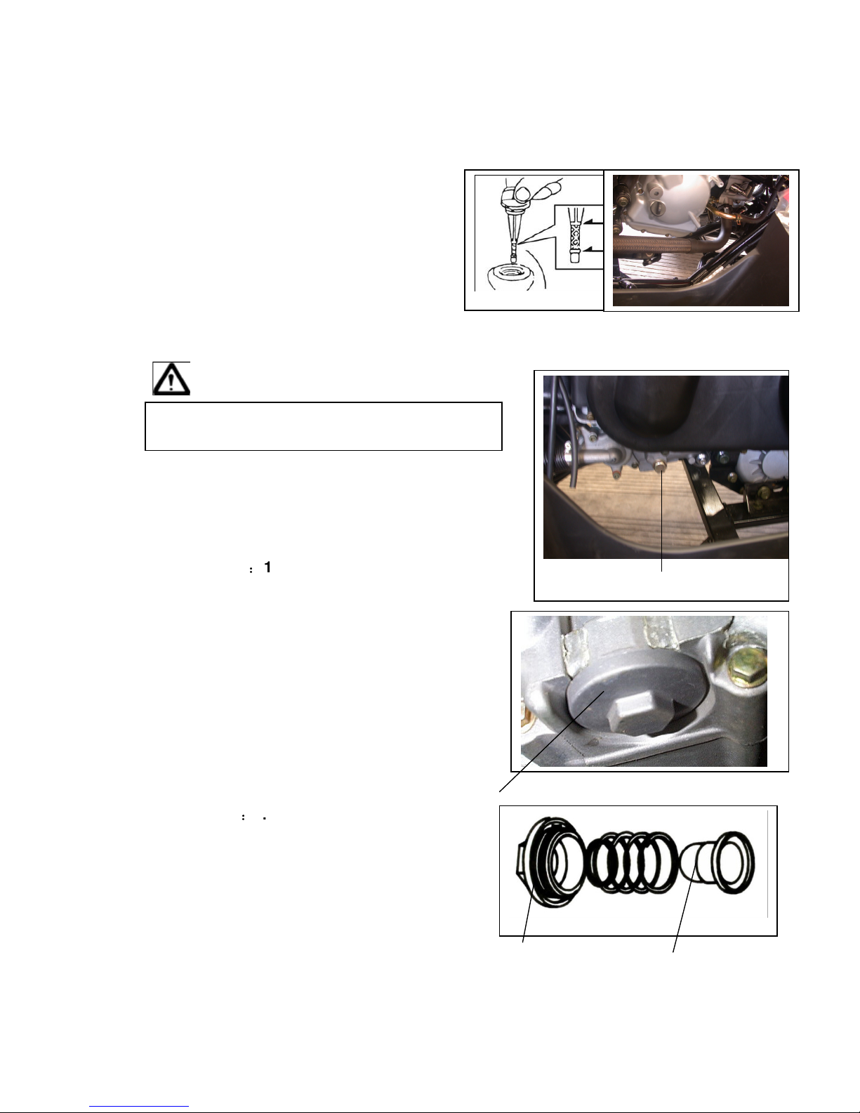
4-5 Engine Oil Strainer Clean
Drain engine oil out.
Remove oil strainer and spring.
Clean oil strainer.
Check if O-ring can be re-used.
Install oil strainer and spring.
Install oil strainer cap.
Oil strainer cap
Torque value:1.5~3.0kgf-m
Add oil to crankcase (oil viscosity SAE 10W-40)
Recommended using King serial oil.
Engine oil capacity: 1000c.c. when replacing
Install dipstick, start the engine for running
several minutes.
Turn off engine, and check oil level again.
Check if engine oil leaks.
O-ring Oil strainer
Drain bolt
18
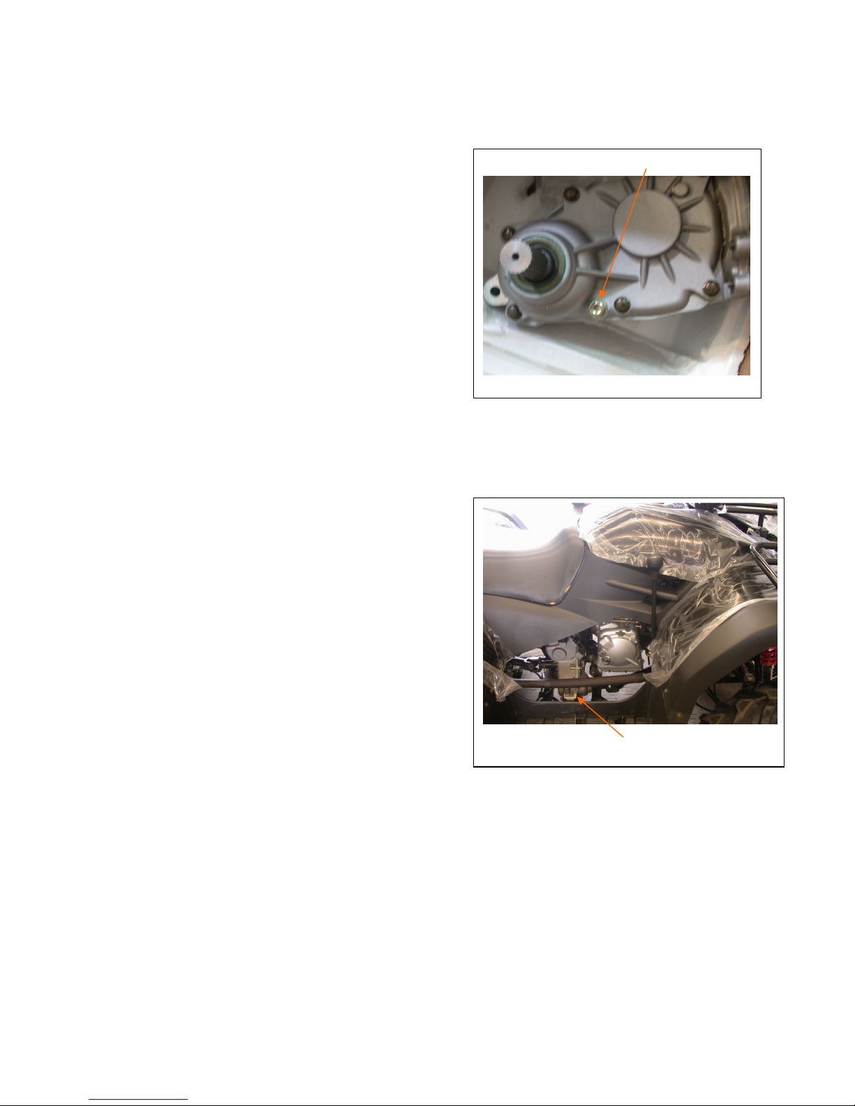
4-6 Gear Oil
Gear Oil Change
Remove oil join bolt.
Remove drain bolt and drain gear oil out.
Install the drain bolt after drained.
Torque value: 1.0~1.5kgf-m
Make sure that the drain bolt washer can be
re-used.
Add oil to specified quantity from the join hole.
Gear Oil Quantity: 650c.c. when replacing
Make sure that the join bolt washer can be
re-used, and install the bolt.
Start engine and run engine for 2-3 minutes.
Turn off engine and make sure that oil level is
in correct level.
Make sure that no oil leaking.
Gear oil drain bolt
Gear oil join bolt
19
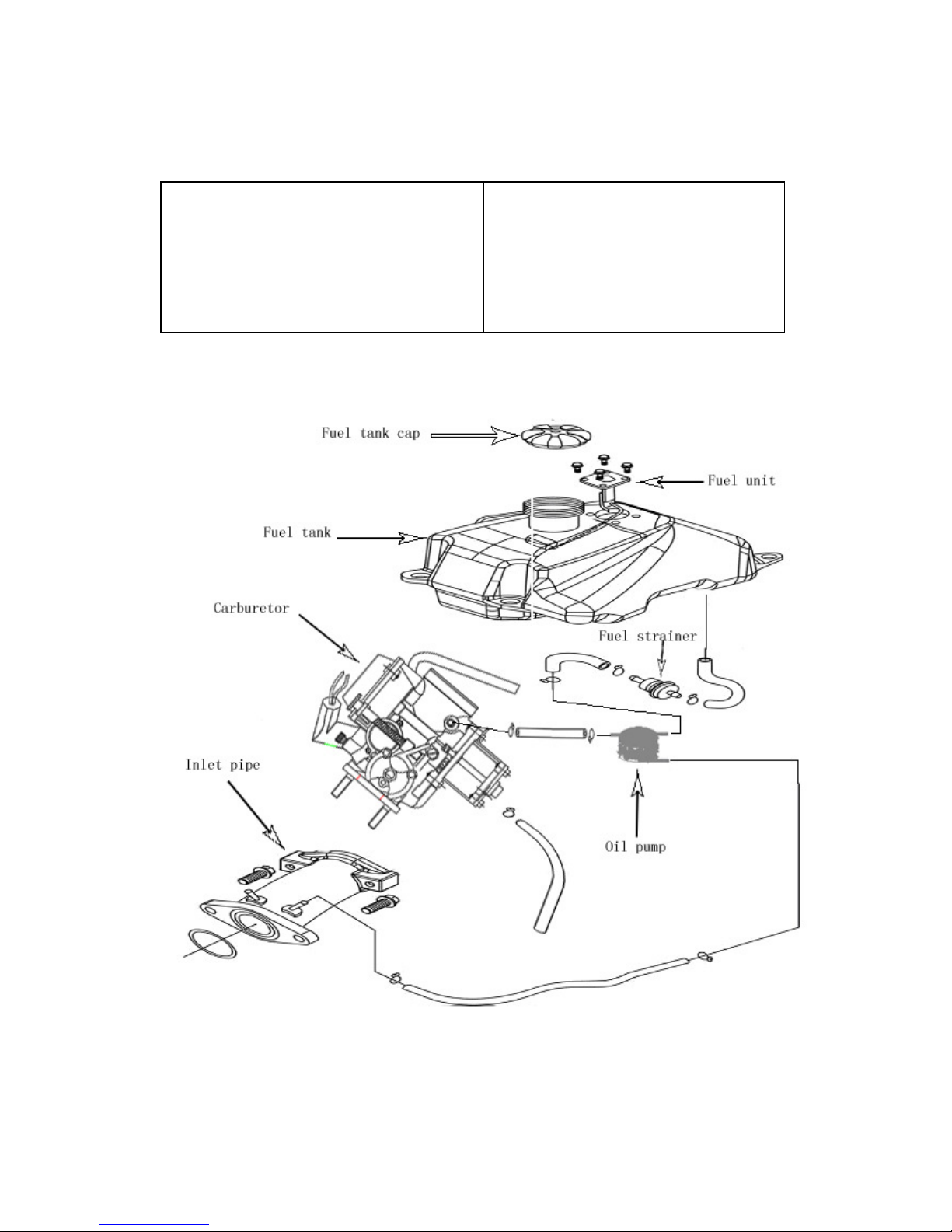
5. FUEL SYSTEM
5-1 Mechanism Diagram
5-2 Precautions in Operation
5-3 Trouble Diagnosis
5-4 Carburetor Remove / Install
5-5 Air Cut-Off Valve
5-6 Throttle Valve
5-7 Float Chamber
5-8 Adjustment of Idle Speed
5-9 Fuel Tank
5-10 Air Cleaner
5-1 Mechanism Diagram
20
5-2 Precautions in Operation
General Information
Warning
Gasoline is a low ignition point and explosive materials, so always work in
a well-ventilated place and strictly prohibit flame when working with
gasoline.
Cautions
●●●●
Do not bend off throttle cable. Damaged throttle cable will make
unstable drive-ability.
●●●●
When disassembling fuel system parts, pay attention to O-ring
position, replace with new one as re-assembly
●●●●
There is a drain screw in the float chamber for draining residual
gasoline.
●●●●
Do not disassemble air cut valve arbitrarily.
Specification
ITEM
UA2
5A
Carburetor diameter
I.D. number
Fuel level
Main injector
Idle injector
Idle speed
15
00 ± 100rpm
Throttle handle clearance
2~5 mm
Pilot screw
Tool
Special service tools
Vacuum/air pressure pump
Fuel level gauge

21
5-3 Trouble Diagnosis
Poor engine start
No fuel in fuel tank
Clogged fuel tube
Too much fuel in cylinder
No spark from spark plug(malfunction of ignition
system )
Clogged air cleaner
Malfunction of carburetor chock
Malfunction of throttle operation
Stall after started
Malfunction of carburetor chock
Incorrect ignition timing
Malfunction of carburetor
Dirty engine oil
Air existing in intake system
Incorrect idle speed
Rough idle
Malfunction of ignition system
Incorrect idle speed
Malfunction of carburetor
Dirty fuel
Intermittently misfire as acceleration
Malfunction of ignition system
Late ignition timing
Malfunction of ignition system
Malfunction of carburetor
Power insufficiency and fuel consuming
Fuel system clogged
Malfunction of ignition system
Mixture too lean
Clogged fuel injector
Vacuum piston stick and closed
Malfunction of float valve
Fuel level too low in float chamber
Clogged fuel tank cap vent
Clogged fuel filter
Obstructed fuel pipe
Clogged air vent hose
Air existing in intake system
Mixture too rich
Clogged air injector
Malfunction of float valve
Fuel level too high in float chamber
Malfunction of carburetor chock
Dirty air cleaner
22
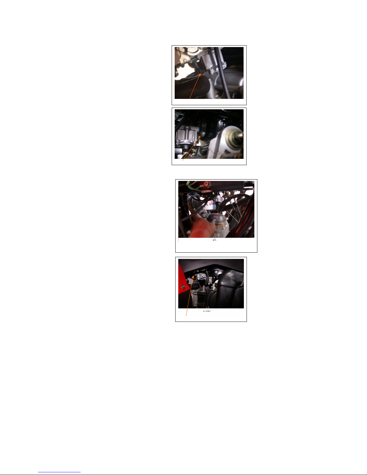
5-4 Carburetor Remove / Install
Removal
Drain out fuel in the float chamber.
Disconnect the fuel hose.
Release the clamp strip of air cleaner.
Remove the carburetor upper parts from the
carburetor.
Release the 2 nuts of carburetor insulator,
and then remove the carburetor.
Installation
Install in reverse order of removal procedures
DRAIN BOLT
CLAMP
2 NUTS
Throttle line
23
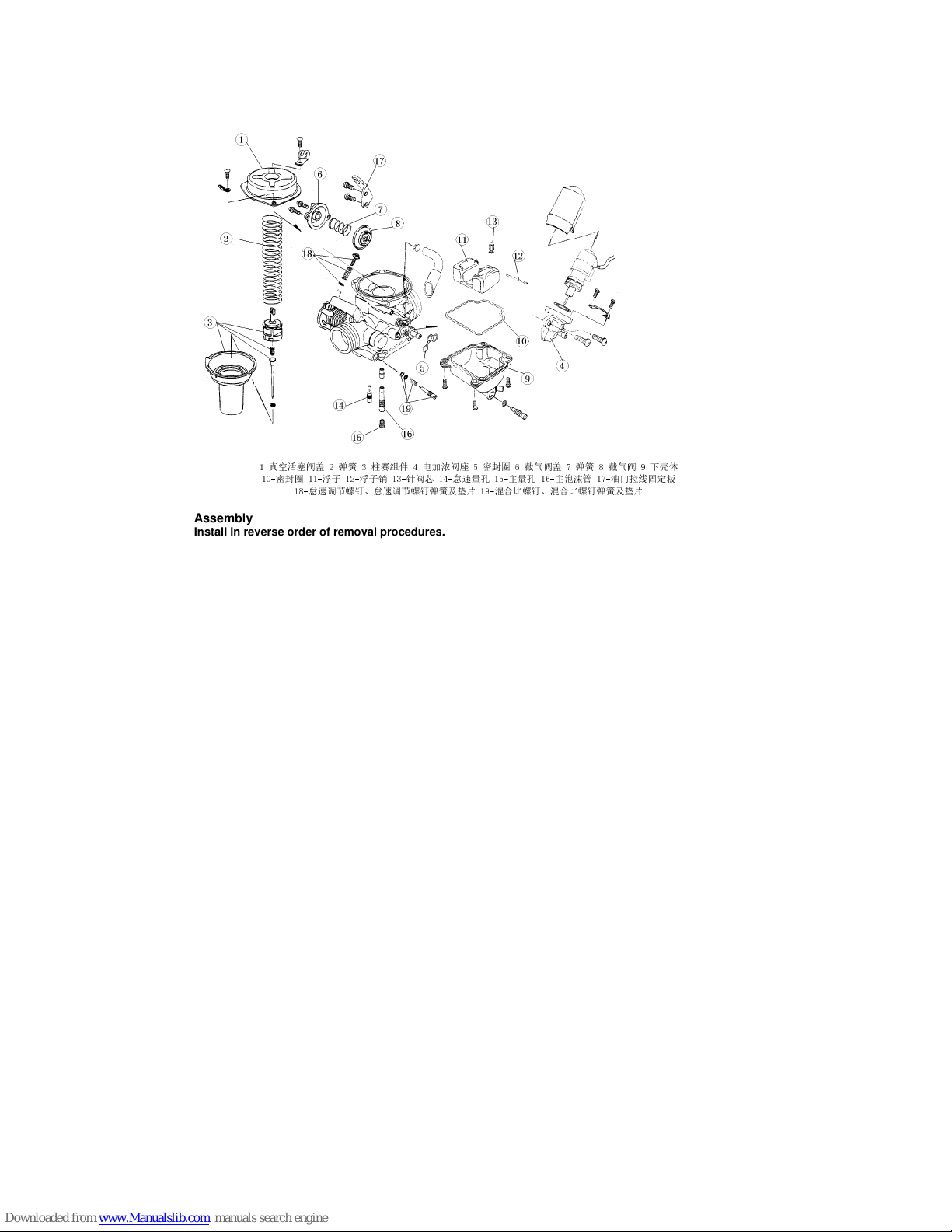
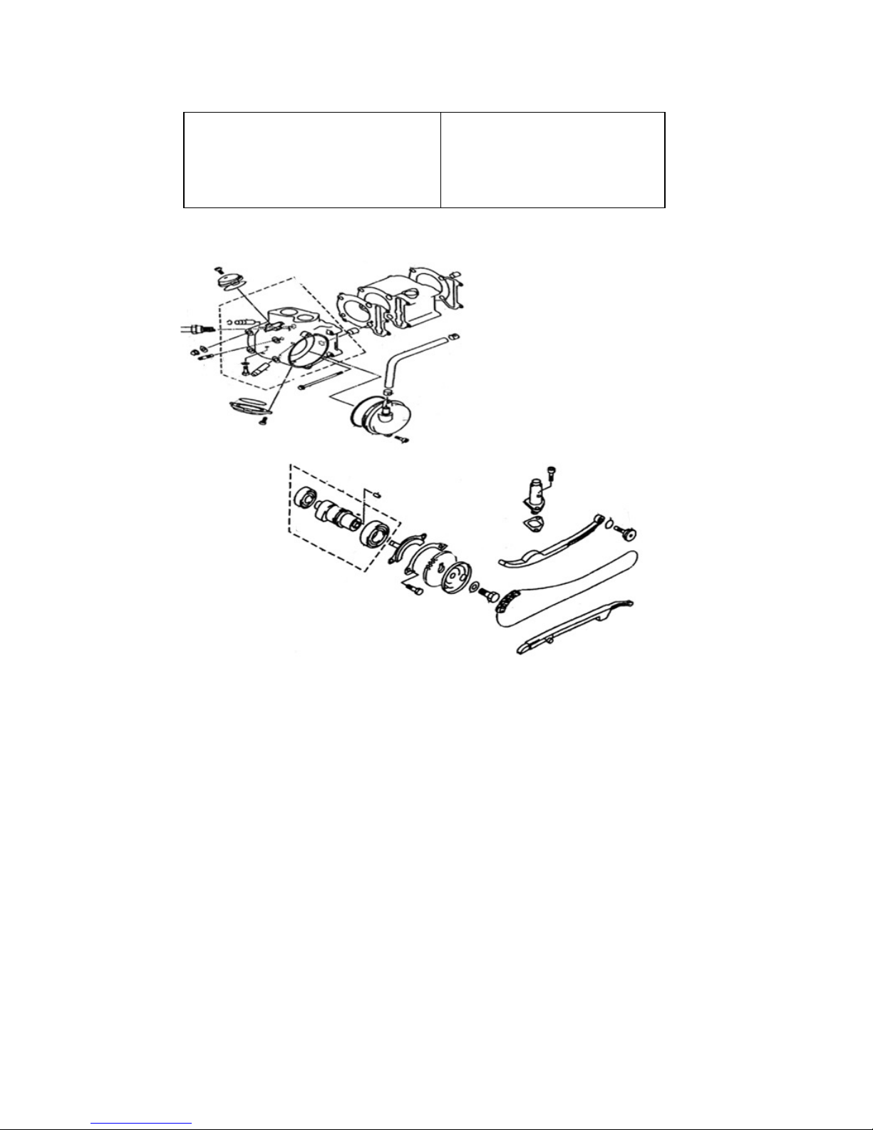
5-5 Air Cut-Off Valve
Disassembly
1-真空活塞阀盖 2-弹簧 3-柱赛组件 4-电加浓阀座 5-密封圈 6-截气阀盖 7-弹簧 8-截气阀 9-下壳体
10-密封圈 11-浮子 12-浮子销 13-针阀芯 14-怠速量孔 15-主量孔 16-主泡沫管 17-油门拉线固定板
18-怠速调节螺钉、怠速调节螺钉弹簧及垫片 19-混合比螺钉、混合比螺钉弹簧及垫片
Assembly
Install in reverse order of removal procedures.

24
5-6 Throttle Valve
Disassembly
Remove carburetor upper parts, and
then remove throttle valve and throttle
cable.
Disconnect the throttle cable from the
throttle valve and remove the valve spring.
Remove the fuel needle clamp and fuel needle
Assembly
Place the fuel needle onto the throttle valve
and clip it with needle clamp.
Install the sealed cap, carburetor upper part,
and throttle valve spring.
Connect the throttle valve cable to the throttle
valve.
Install the throttle valve into the carburetor body
Caution
Align the groove inside the throttle valve with
the throttle stopper screw of the carburetor body.
25
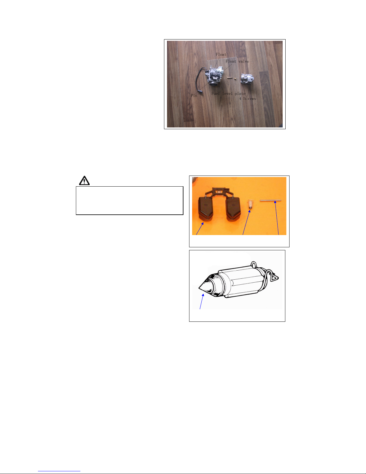
5-7 Float Chamber
Disassembly
Remove 4 mounting screws and remove
float chamber cover.
Remove the fuel level plate, float pin,
float and float valve.
Inspection
Check float valve and valve seat for damage,
blocking.
Check float valve for wearing, and check
valve seat face for wear, dirt.
Caution
Caution In case of worn out or dirt, the float valve
and valve seat will not tightly close causing fuel
level to increase and as a result, fuel flooding. A
worn out or dirty float valve must be replaced
with a new a new one.
Float Float valve Pin
Check for wear or damage
26
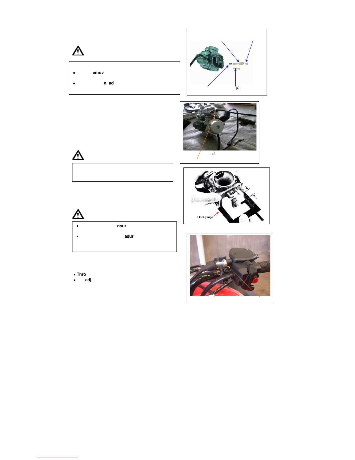
Remove main jet, needle jet holder, needle jet,
slow jet and air adjustment screw.
Caution
Clean jets with cleaning fluid. Then use
compressed air to blow the dirt off.
Blow carburetor body passages with
compressed air.
Assembly
Install main jet, needle jet holder, needle jet,
slow jet and air adjustment screw
Caution
Install the float valve, float, and float pin.
Checking fuel level
Caution
Installation of carburetor
Install carburetor in the reverse order of removal.
Following adjustments must be made after installation.
˙˙˙˙
Throttle cable adjustment.
˙˙˙˙
Idle adjustment
Set the air adjustment screw in according to
number of turns noted before it was removed.
Take care not to damage jets and adjust screw.
˙˙˙˙
Before removing adjustment screw, turn it all the
way down and note the number of turns.
˙˙˙˙
Does not turn adjust screw forcefully to avoid
damaging valve seat face.
˙˙˙˙
Check again to ensure float valve, float for
proper installation.
˙˙˙˙
To ensure correct measurement, position the
float meter in such a way so that float chamber
face is vertical to the main jet.
Needle jet holder Main jet
Needle jet Slow jet
Air adjustment screw
Throttle adjustment screw lock nut
27
5-8 Adjustment of Idle Speed
Caution
˙˙˙˙
Air screw was set at factory, so no
adjustment is needed. Note the number of
turns it takes to screw it all the way in for
ease of installation.
˙˙˙˙
The parking brake must be used to stop the
ATV to perform the adjustments.
Use a tachometer when adjusting engine RPM.
Screw in air adjustment screw gently, then back
up to standard turns.
Standard turns: 1 1/2turns
Warm up engine; adjust the throttle stopper screw
of throttle valve to standard RPM.
Idle speed rpm: 1500 ± 100 rpm
Connect the hose of exhaust analyzer to exhaust
Front end. Press test key on the analyzer.
Adjust the pilot screw and read CO reading on the
Analyze
CO standard value: 1.0~1.5 %
Accelerate in gradual increments; make sure rpm
and CO value are in standard value after engine
running in stable. If rpm and CO value fluctuated,
repeat the procedures described above for adjusting
to standard value.
Parking brake
Air adjustment screw
throttle stopper screw
28
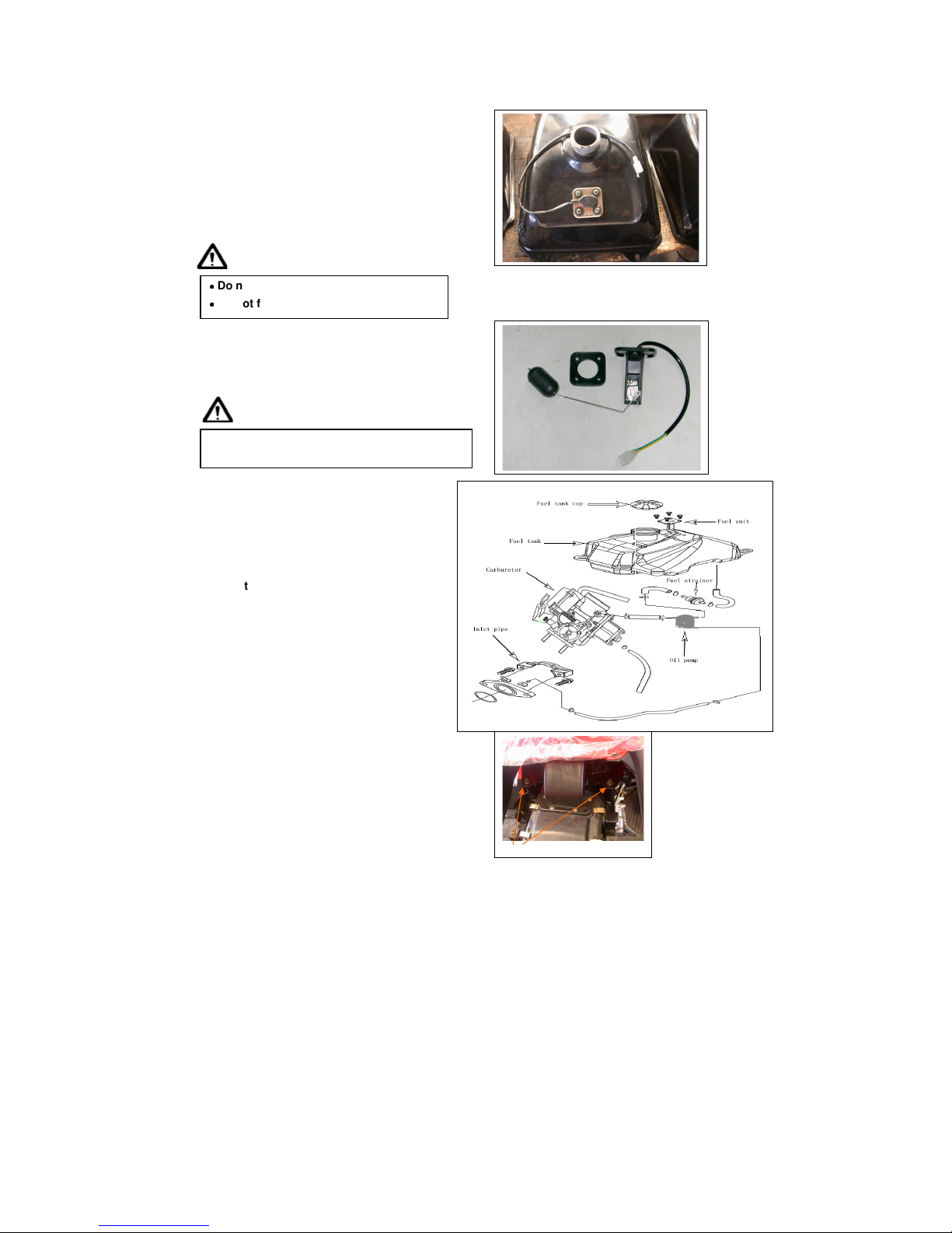
5-9 Fuel Tank
Fuel unit removal
Open the seat.
Remove the front cover and fuel tank.
Remove the side covers and lower side covers.
Remove the front fender.
(Covers remove please
refer chapter
13)
Disconnect fuel unit coupler.
Remove fuel unit (4 bolts).
Caution
˙˙˙˙
Do not bend the float arm of fuel unit
˙˙˙˙
Do not fill out too much fuel to fuel tank.
Fuel unit installation
Install the gauge in the reverse order of removal.
Caution
Do not forget to install the gasket of fuel unit or
damage it.
Fuel tank removal
Open the seat.
Remove the front cover and fuel tank.
Remove the side covers and lower side covers.
Remove the front fender.
(Covers remove please
refer chapter
13)
Disconnect fuel unit coupler.
Remove fuel unit (4 bolts).
Remove the fuel tube.
Remove the
vacuum tube
.
Remove fuel tank front and rear side 4 bolts,
and then remove fuel tank
Installation
Install the tank in the reverse order of removal
Rear nuts
29
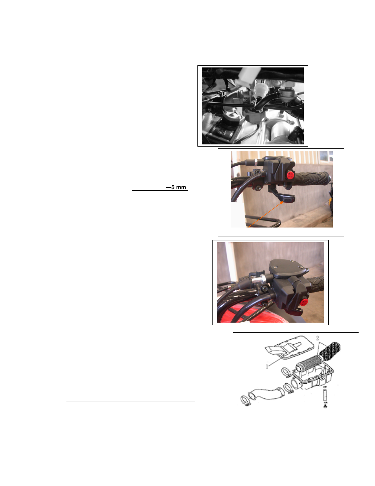
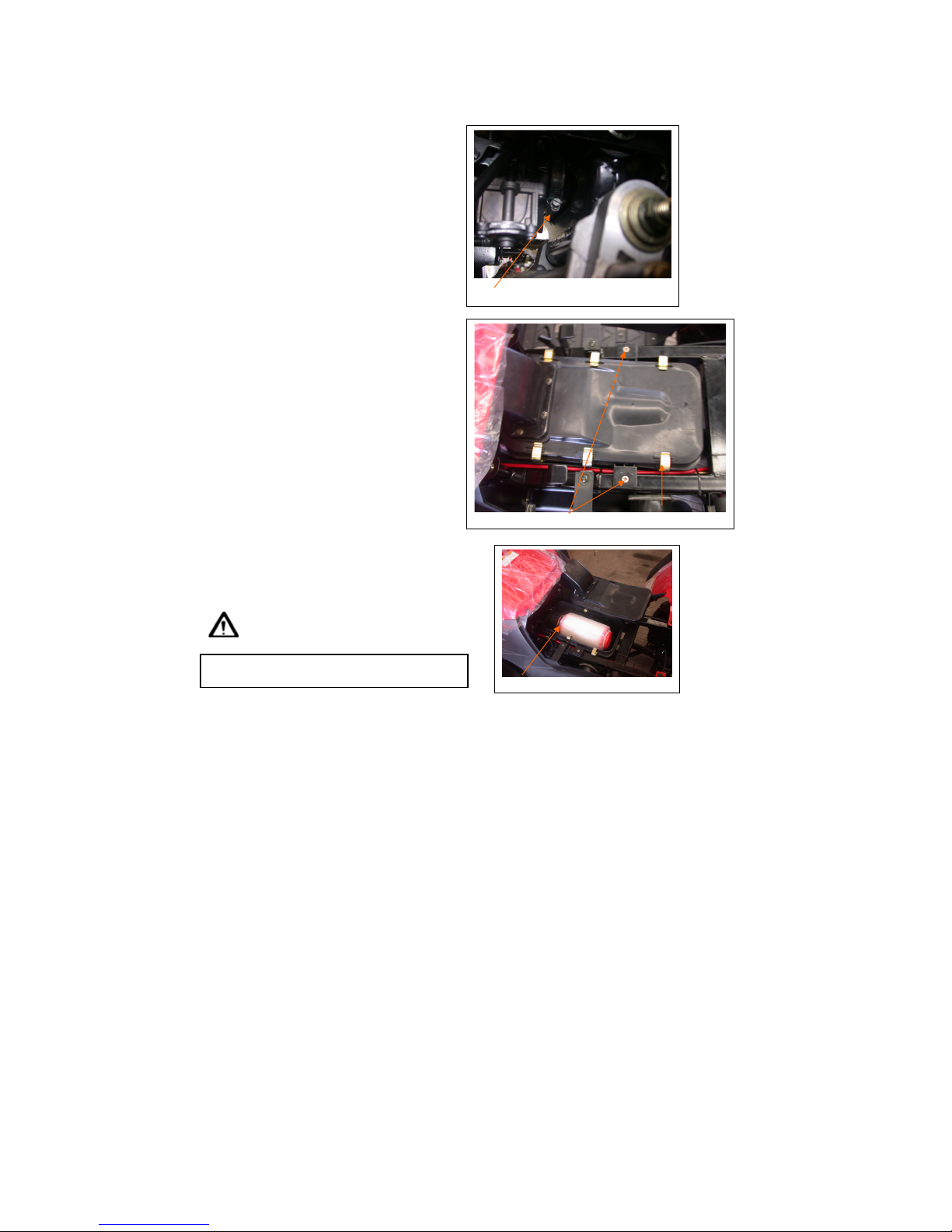
5-10 Air Cleaner
Removal
Loosen the clamp strip of air cleaner and
carburetor,and then remove the vapor hose.
Loosen the clamp strip of air cleaner, and then
remove the air cleaner vapor hose.
Remove the air cleaner (2 bolts).
Installation
Install the tank in the reverse order of removal.
Cleaning air cleaner element
Remove the air cleaner cover (6 catch hooks).
Remove element mounting screw.
Loosen the clamp strip of air cleaner element,
and then remove the air cleaner element.
Clean the element with non-flammable or
high-flash point solvent and then squeeze it for
dry.
Caution
Never use gasoline or acid organized solvent to
clean the element.
Soap the element into cleaning engine oil and then
squeeze it out. Install the element onto the element
seat and then install the air cleaner cover.
CLAMP
2 BOLTS 6 HOOKS
CLAMP
30
6. CYLINDER HEAD/VALVE
6-1 Mechanism Diagram
6-2 Precautions in Operation
6-3 Troubleshooting
6-4 Cylinder Head Removal
6-5 Cylinder Head Inspection
6-6 Valve Stem Replacement
6-7 Valve Seat Inspection and Service
6-8 Cylinder Head Reassembly
6-9 Cylinder Head Installation
6-10 Valve Clearance Adjustment
6-1 Mechanism Diagram
 Loading...