

KEEWAY ATV250 Service And Maintenance Manual
1
ATV Service and
Maintenance Manual
Model: ATV250
C o p y r i g h t :
K E E WAY I N T E R N AT I O N A L D E V E L O P M E N T C O . , LT D .
FEB.2006

2
If you have any problems can not fnd the solution in this manual,
please fell free to contact with:
KEEWAY INTERNATIONAL DEVELOPMENT CO.,LTD
2000 SZENTENDRE U.8 KOZUZO. HUNGARY
TEL:0036-26-500005
FAX:0036-26-312034
EMAI: info@keewaymotor.com
Our engineer are very glad to give you the necessary assistance and help.

3
C O N T E N T
A. General information
1. Basic terminology- Engine
2. Engine types-4 stroke engine work cycle/illustrations
3. Workshop safety
Service rules
Electricals safety
B Product
1. Technical specifications
2. Special service tools
3. Engine and transmission
a) Specified torque value
b) Small but vital component /Nondirectional fitment-parts of engine
c) Engine removal /installation
d) Engine assembly
e) Radiator assembly
f) Engine removal /installation
Intake pipe of carburetor /Gear case/Cylinder head /Piston/Left crankcase cover / Water
pump/Right crankcase cover/Spare parts for right crankcase cover/ Clutch/Drive gear
COMP/Driven wheel clutch COMP/Crankcase/Speed gear box
g) Power flow chart
h) Lubrication system
i) The setup of valve interval
j) Engine cylinder compression test
k) Some important dimensions-engine
Fuel –air system - Air filter/Carburetor assy
- Mixed air ( air burning) system
- Disassembly and assembly of the carburetor
4. Chassis group
a) Specified torque value – chassis
b) Sub assembly – chassis
(i) Front wheel assy
(ii) Front disc brake assy
(iii) Redirector, upper and lower swing arm assy
(iv) Steering system
(v) Rear wheel, transmission system assy
(vi) Rear hydraulic brake assy
(vii) Rear swing arm assy
c) Important tips on vehicle assembly
d) Important dimensions of vehicle
5. Electricial /electronics

4
a) Magneto(A.C.G)
b) Wiring diagram
c) Ignition circuit test
d) The relational matters of the battery
e) The process of debugging of battery
f) Signal system circuit
g) Battery charging system circuit
h) Power flowing chart of electric start
i) Removal and replacement of various bulbs
j) Testing procedure of electrical components
k) Important specifications -electrical
C Others
1. Pre-delivery inspection (P.D.I)/check points
2. Periodical maintenance
3. Do’s and don’t’s
4. Safety ride
(i) Riding posture
(ii) Effective braking
5. Trouble shooting
5
A
GENERAL INFORMATION
2
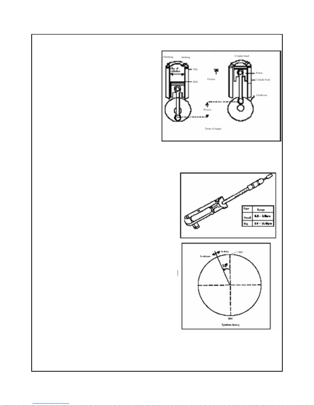
B a s i c t e r m i n o l o g y - E n g i n e
A.... Dead center
Either of the two limits in the cylinder at which the
piston changes its moving direction.
TDC ------- top dead center(the upper limit of the piston
movement)
BDC------- bottom dead center(the lower limit of the
piston movement)
B. Bore
Bore is the internal diameter of the cylinder block
C. Stroke
The length of the piston travel is called the stroke.
When piston moves from TDC to BDC, it is one stroke.
D.
D. D.
D. Displacement
The volume swept by piston when traveling from TDC to BDC is
called displacement. Normally displacement is measured in
CC( cubic centi-meter) e.g. 75cc, 125cc etc. and it varies
according to engine type.
E. Torque
Torque is a kind of twisting or turning force. When we loosen
or tighten the screws or bolts, we impart the torque to them.
The engine imparts torque to the wheels to drive them, and
imparts more torque when it climbs. The produce of strength and
the arm of force equal to the torque, and its unit is kilogram-meter.
F. The timing of ignition.
The ignition is timed in order to control the combustion
in the firebox. The timing ignition of ATV250 engine
changes as follows: 15
0
。
When it is 5000RPM.
3
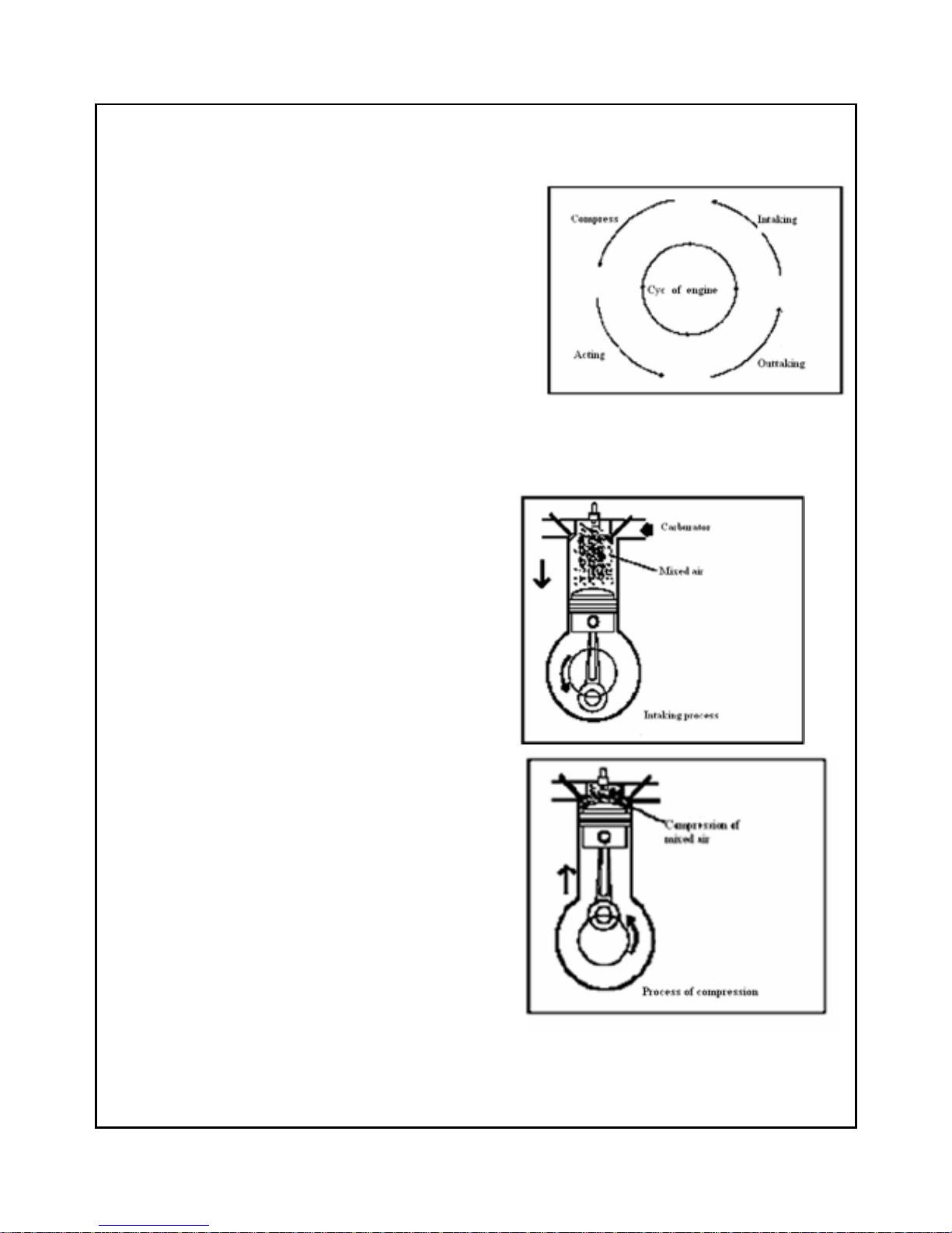
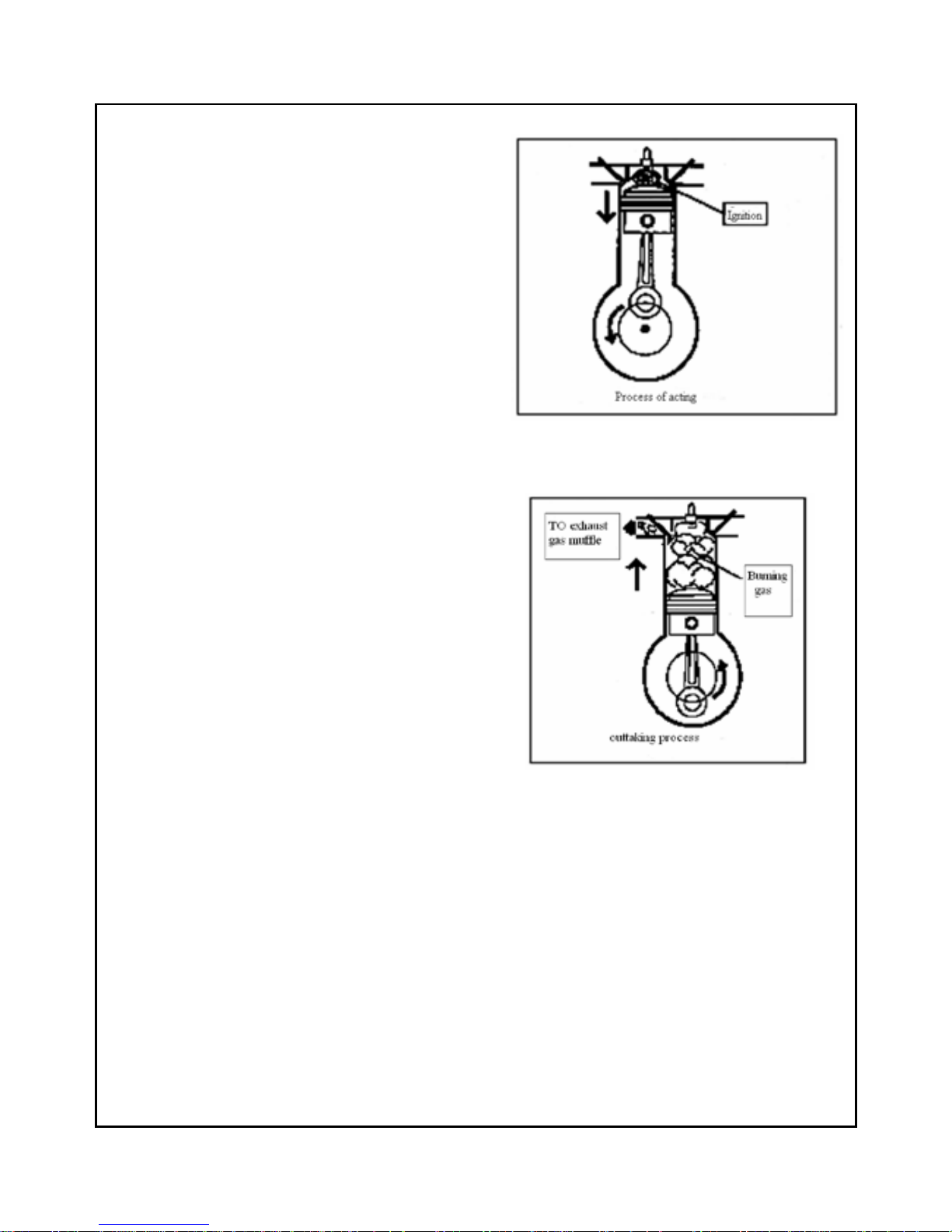
Engine work cycle
Each 4-stroke petrol engine has the following 4 processes the completion of these 4 processes is termed as one cycle
of the engine work.
1、 Suction: air and fuel mixture is sucked inside the cylinder
2、 Compression: air and fuel mixture is being compressed in cylinder
3、 Power : after spark, mixture explodes and expand to push dam
piston, thus crankshaft output machanical energy through con-rod.
4、 Exhaust : the gases are expelled
4 - s t ro k e e n g i n e w o r k c y c l e
A::::SUCTION STROKE
1、 The crankshaft turns in the counter clockwise direction
2、 The motion of the crankshaft acts on the con-rod to pull the
piston down.
3、 As the piston moves from TDC to BDC, the intake valve
opens and air-fuel mixture is drawn into cylinder
B::::Compression stroke
1、 The crankshaft continues running, and brings the
piston goes from the BDC to the TDC by the connecting rod.
2、 The mixing air is pressed into a narrow room between the
cylinder head and the top of piston which is called firebox.
4
C::::Power stroke
1. Spark plug lights the compressed air- fuel mixture.
2. The combustion of air-fuel mixture causes the
the temperature and the pressure increase in the
firebox, the air expands, the power forces the piston
to push the protuberance down.
3. The power forced on the plug transfers to the
crankshaft through connecting rod, then the crankshaft
speeds up, the expanding of mixed air provides
power for the engine.
D::::Exhaust stroke
1、The air outtake valve opens when the piston goes
The bottom of the process.
2、The revolvable crankshaft pushes the piston towards the
cylinder head because of inertia.
3、Then the piston goes towards the cylinder head, the
burning gas is pushed out from air outtake valve, the
air outtake valve closes when piston reach the top end
of process.
5
Wo r k s h o p s a f e t y
Warning
Never use worn-out Tools which may slip and
cause injury to you.
Warning
Do not smoke or allow flames or spark near
petrol which is highly explosive as well as
inflammable.Work in a well ventilated area.
Warning
Do not spill oil on the workshop floor as one
may slip and get injuried.Always keep it neat
and clean.
Warning
Never run the engine in an enclosed or
badly-ventilated area for a long time because the
exhaust contains poisonous gas.
Warning
Never use dry brush or compressed air to clean
brake assembly/components because inhaled
airborne asbestos fibres may cause cancer or
respiratory disease.
Warning
The battery electrolyte contains sulphuric
acid.Protect your eyes,skin and clothing.In
case of contact,flush thoroughly with water
immediately & call a doctor.Electrolyte
should be kept at a safe place out of reach
of children.
Warning
Always ensure mutual safety when working
with a partner.
S e r v i c e r u l e s
1. Use only genuine KEEWAY parts and recommended grade of lubricants at specified parts and
points.
2. Use right/proper (general and special) tools at right place.
3. Install new gaskets,O rings,oil seals,clips,split pins and so on,while reassemblying.
4. Use only Metric nuts and bolts(MKS system).
5. When tightening nuts or bolts,start first with larger diameter or centre ones.Then tighten the
others to the specified torques diagonally (criss-cross pattern).
6. After reassemblying,checking all nuts & bolts for proper tightening by torque wrench,check free
operation and also movement of the moving components.
7. Clean parts before measurement and get rid of oil,if any.Lubricate working parts lightly by oil
while assembly.
8. When engine and transmission components are dismantled and kept for a longer period,coat the
mating surface with a lubricant to prevent rusting and cover them,to avoid dust.
6
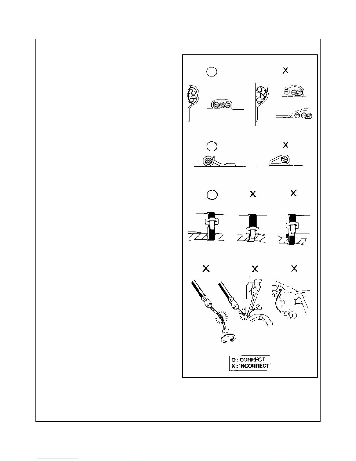
Electricals safety
1. A loose wire harness can be a safety
hazard.After clamping,check each wire to be
sure it is secure.
2. Don’t curve clamps towards welds.
3. Secure wire bands to the frame at the
designated locations.Tighten the wire bands
(strap) so that the insulated surfaces can
contact the wire wirenesses.
4. Route wire harnesses and cables to avoid
frame ends or sharp edges.
5. Route wire harnesses to avoid the projected
ends of bolts and screws.
6. Keep wire harnesses and cables away from the
hot parts or area where they might be pinched
between the moving parts.
7. Wire harnesses routed along the handlebars
should not be pulled tight or have excessive
slack or be pinched or interfere with adjacent
or surrounding parts in all steering positions.
8. Check that the wire harnesses are not twisted
or kinked.
9. Ascertain that there is a damage of connector
cover,and if its terminal is opened
excessively,before connection.
10. Protect wires and harnesses with tape or a tube
if they contact a sharp edge or corner.
11. After repairing wire harnesses,wrap with
protective tape or replace them.
12.Don’t bend or twist the control
cables.Damaged control cables will not
operate smoothly and may stick or bind .

7
B
PRODUCT
8
Te c h n i c a l s p e c i f i c a t i o n s
Item Parameter
Total length 1950mm
Total width 1100mm
Total height 1110mm
Seat height 840mm
Wheelbase 1290mm
Front wheel
860mm
Tread
Rear wheel 830mm
Min process from the ground 150mm
ATV250
Net weight 238kg
E n g i n e
Type
Disposal of cylinder
Cylinder diameter * stroke
Air capability
Rate of compression
Air mixing device
Machine oil cubage of engine
Machine oil type of engine
Lubrication system
Oil pump type
Air cleaner
Pressure of cylinder
Intake valve open
close
Outtake valve open
close
Clearence of valve jib intake
(in cold condition ) outtake
Idle speed
Max torque
Max outaking power
Starting system
Net weight of engine
Horizontal 、 singel room 、
water
cooling、4-strokes
Incline 100 according to the level
69×66.8
249.8CC
10:1
Top play camshaft
1.4L
SF LEVER SAE10W/40
Pressure lu
brication and splash
lubrication
Rotor type
12±1kg/cm2
50BTDC
250ABDC
300BBDC
50ATDC
0.03~0.05mm
0.05~0.06mm
1500±100(r/min)
18.5/5000(N.m/r/m)
12.4/6500(KW/r/m)
Electric start
46kg
9
Carburetor
Manufacturer/type of carburetor
Identify NO.
Diameter of throat pipe
Size of main muzzle
Size of idle speed muzzle
Clip position of oil needle
Idle speed air adjusting screw
Hight of floater
KEEWAY-Wenling-China,vacuum chaff type
PD31
31mm
#294
#34
The third case from the top
Exit1
2
1
±
2
1
lap
15±1mm
Type
Front shock absorber
Rear shock absorber
Specification of front wheel
Specification of reat wheel
Pressure of tyre Driver Front
Rear
Chassis
Front brake
Rear brake
Volume of tank
Oil containing volume of tank
Hydraulic spring type
Hydraulic spring type
21×7-10
22×11-10
0.43-0.58kg/cm2(6-8Psi)
0.43-0.58kg/cm2(6-8Psi)
Disc、Operate by right hand Dia.of brake plate 168mm
Disc、Operate by right hand Dia.of brake plate 220 mm
9.3L
1L
Item Parameter Type
Drive
system
Clutch system
Gear framework type
Gear framework operation mode
Primary speed-down rate
Automatic gear range
Gear box
Gear speed-down rate First level
Second level
Max speed
V model belt type
Automatic gear with reverse gear
Automatic centrifugal type
1
0.88~2.2
Two levels gear case
2.667(40/15)
2.313(37/16)
10
To o l S l i s t i n g
Item Parameter Specs
Electric
Ignition system
Timing ignition ‘F’ mark
‘Ⅱ’Full advance
Alternator(magnetic electrode)
Spark plug
Clearance of spark plug
fuse
battery
TCI
1500RPM before TDC 100±20
3500RPM before TDC 320±20
310W@4000RPM
D7RTC
0.6~0.7mm
15A
12N9-4B-1
Light
Front light(high beam/dipped beam)
Tail light/brake light
Indicator light of machine oil
Indicator light of forward gear
Indicator light of empty gear
Indicator light of reverse gear
12V 18/18W
12V/10W
12V/1.7W
12V/1.7W
12V/1.7W
12V/1.7W
Model Color Capability Code
VENTO
Engine NO.
Frame NO.
Green
Desert yellow
C.D.I.
Front and real disc
breakers

11
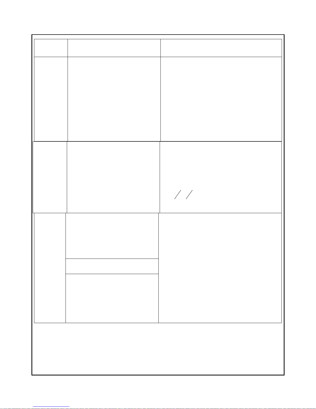
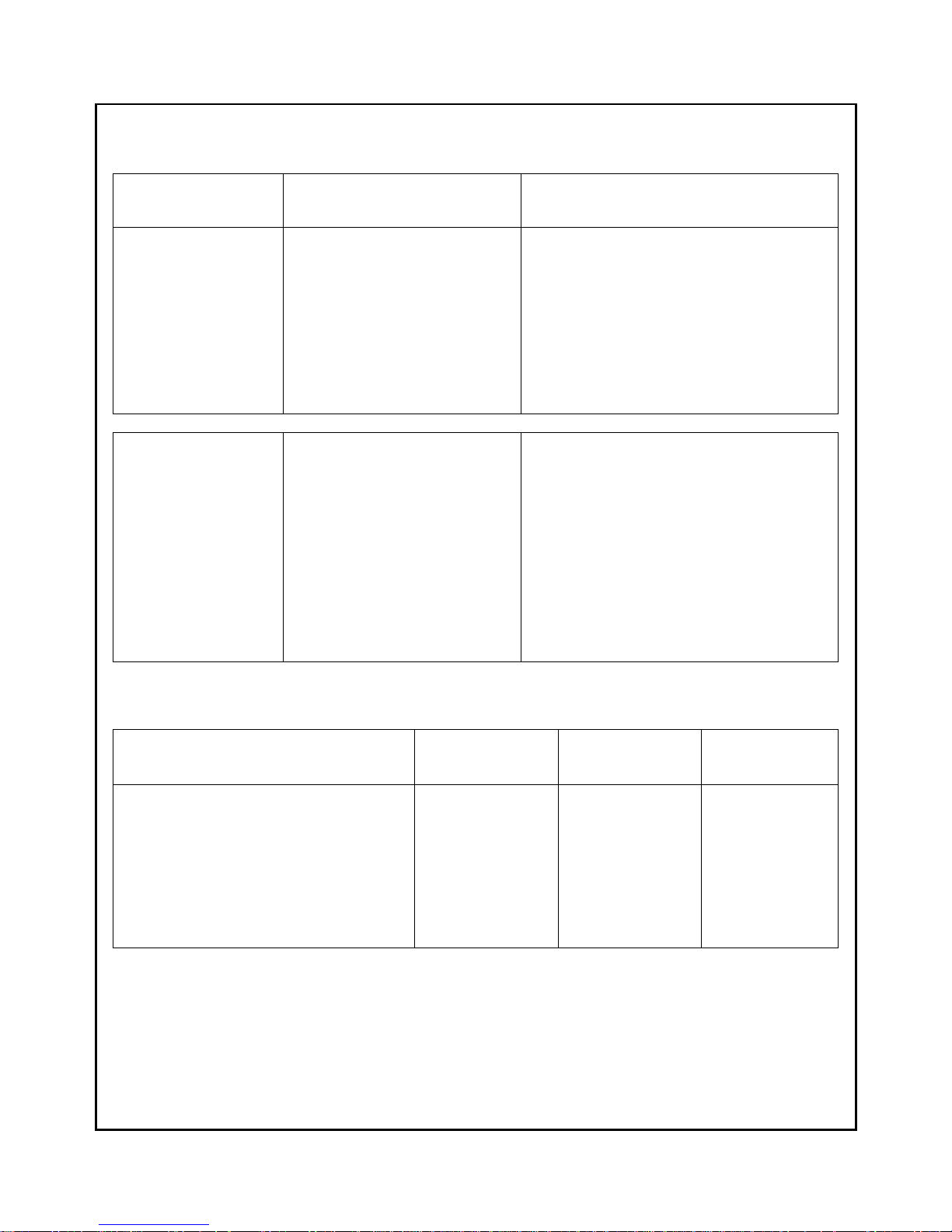
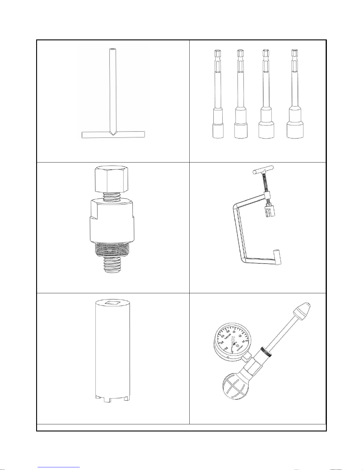
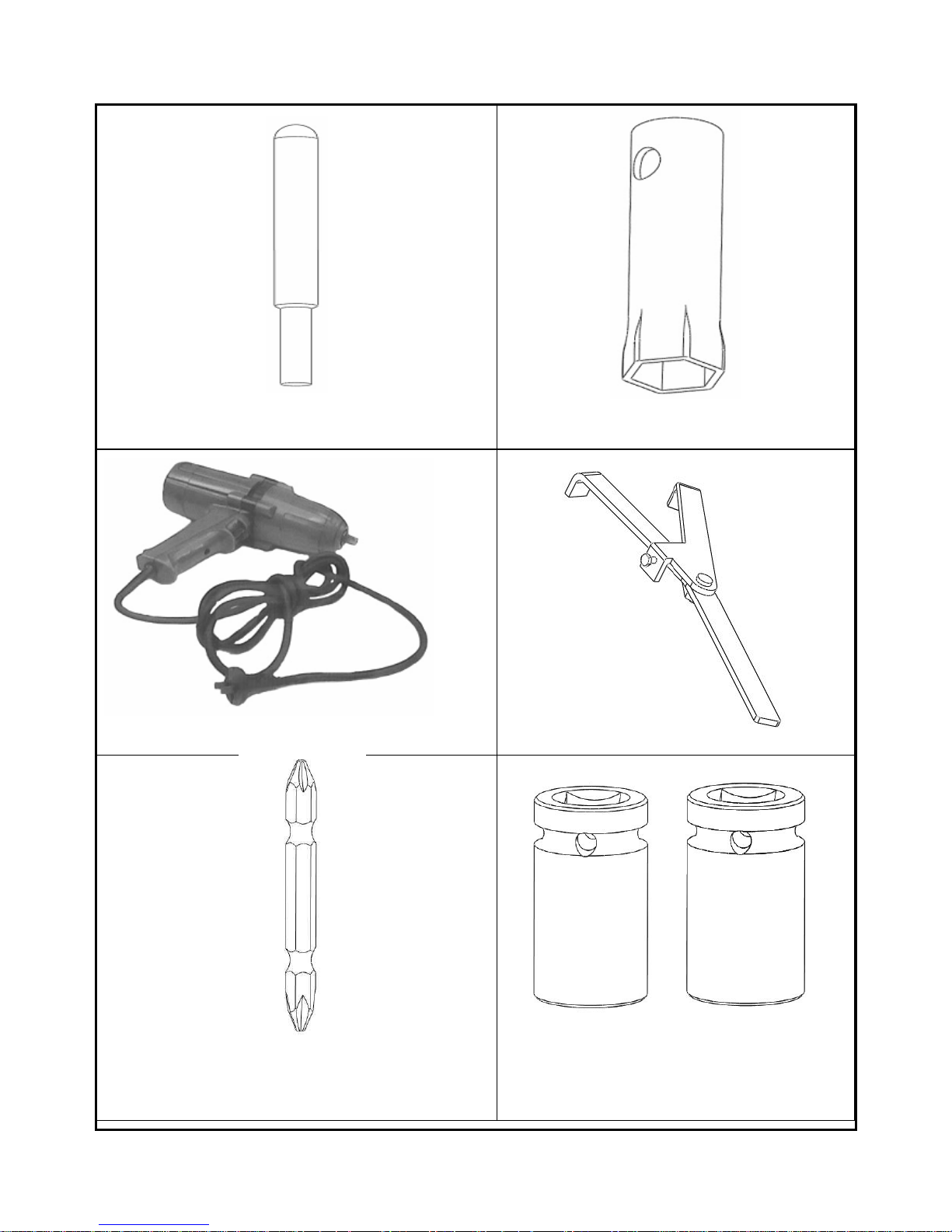
The tools are indispensable to install or dischange the engine down blow:
NO. Code of tools use
1
2
3
4
5
6
7
8
9
10
11
12
T01
T02
T03
T04
T05
T06
T07
T08
T09
T10
T11
T12
“T”shape sleeve
Sleeve (7、8、10、12、13)
Assembly and disassembly tools of stator
Assembly and disassembly tools of air valve spring
Assembly and disassembly tools of clutch lock nut
Pressure chart of cylinder
Assembly and disassembly tools of piston pin
Assembly and disassembly tools of spark plug
Electric assembly and disassembly tools of clutch lock nut
Clamp of clutch
Assembly and disassembly tools of bolt
sleeve(17、18)
12
①
②
③
④
⑤
⑥
13
⑦
⑧
⑨
⑩
○
11
○
12
14
S p e c i f i e d t o r q u e v a l u e
NO. Name Qun
Torque((((N.m))))
1
2
3
4
5
6
7
8
9
10
11
12
13
14
15
16
17
18
19
20
21
22
23
24
25
26
27
28
Lock bolt of chain tension pole
Lock bolt of chain tensioner
Lock bolt of cylinder head
Spark plug
Dtud bolt of cylinder head intake valve
Dtud bolt of cylinder head outtake valve
Lock nut of carburetor joint
Lock bolt of stator
Lock bolt of magneto stator loop
Lock bolt of magneto spring loop
Lock bolt of crankcase right cover
Cap of machine oil filter
Lock bolt of oil pump COMParting board
Lock bolt of oil pump gear
Lock bolt of oil pump
Lock bolt of oil pump cover
Lock bolt of clutch out ring
Lock bolt of righ crankcase
Lock bolt of righ and left crankcase
Lock bolt of engine
Lock bolt of left crankcase
Lock bolt of drive wheel
Lock bolt of driven wheel
Lock bolt of driven wheel clutch
Lock bolt of speed gear box cover
Lock bolt of speed gear box oil outtake aperture
Lock bolt of left crankcase oil outtake
Lock bolt of left crankcase orientation bearing
1
2
4
1
2
2
2
1
2
2
9
1
2
1
2
1
3
2
4
2
10
1
1
1
7
2
1
1
10-12
10-12
25-28
15-26
10-12
10-
12
10-12
65-70
10-12
10-12
10-12
55-60
10-12
8-10
10-12
1-3
25-30
10-12
22-25
10-12
10-12
60-65
60-65
55-60
10-12
22-25
40-45
22-25
15
S m a l l b u t v i t a l c o m p o n e n t
Dowel pin-16NOS.
S.NO. Size (mm) Qty. Description Location
1 φ10×15.5 2 Cylinder head and body Engine
2 φ10×14 2 Crankcase and cylinder body Engine
3 φ10×14 2 Right and left crankcase Engine
4 φ10×14 2 left crankcase speed gear box cover Engine
5 φ10×14 2 left crankcase and left cover Engine
6 φ10×14 2 Right crankcase and right cover Engine
7 φ10×14 2 Gear case and left crankcase Engine
8 φ10×14 2 Gear case and gear case cover Engine
O-ring
ringring
ring----9NOS.
S.NO. Size (mm) Qty. Description Location
1 φ58×2.4 2 Adjusting cap of valve Engine
2 φ92.5×3.5 1 Chain wheel cover Engine
3 φ15.6×2.4 1 Outtake pipe of pump Engine
4 φ20×2.5 1 Oil level gauge Engine
5 φ34×3.4 1 Spring cover oil filter Engine
6 φ16×2.5 1 Inspective aperture cover Engine
7 φ9×2 1 Outtake rocker bearing Engine
8 φ1 4.8×1.9 1 Stopper screw Engine
9 φ35×2 1 Intake pipe Engine
10 φ40×2.65 2
Seat of disc break plate、collar of rear
wheelie and transmission shaft
Vehicle
Oil seal- 6NOS.
S.NO. Size (mm) Qty. Description Location
1 25×42×6 1 Intake shaft-crankcase cover Engine
2 32×52×7 1 Transition shaft-left crankcase
Engine
3 30×45×5 1 crank-left crankcase Engine
4 32×52×7 1 Outtake shaft-gear box cap Engine
5 25×35×6 1 Transition shaft-gear box cap Engine
6 14×28×7 1 crank-right cover Engine
7 25×42×8 2 Rear hub Vehicle
8 50×68×8 2 Chain adjuster Vehicle
16
Bearing
S.NO. Code Qty. Description Location
1 6303 1 Transition shaft-speed gear box cover Engine
2 HK15×28×15 1 Idle shaft-speed gear box cover Engine
3 6205 1 Intake shaft- speed gear box cover Engine
4 62/22 1 Transition shaft-left crankcase Engine
5 HK15×28×15 1 Idle shaft-left crankcase Engine
6 6302 1 Intake shaft-left crankcase Engine
7 6306 1 Left crank-left crankcase Engine
8 63/28 1 Right crank-right crankcase Engine
8 K32×40×20 1 Crank pin-bigger end of crank shaft Engine
9 K28×32×17 1 Clutch hub-clutch gear Engine
10 10000903 1 Driven wheel-intake bearing Engine
11 HK205×32×12RS 1 Driven wheel-intake bearing Engine
12 6201 1 Transition shaft-gear box cover Engine
13 6203 1 Outtake shaft-gear box Engine
14 6005-2RS 1 Outtake shaft-gear box cover Engine
15 K16×20×22 1 Reverse gearing drive gear Engine
16 K16×20×22 1 Reverse gearing driven gear Engine
17 60202 1 Camshaft Engine
18 6105 1 Camshaft Engine
19 61905-2RZ 2 Front hub(inside) Vehicle
20 6203-2RS 2 Front (outside) Vehicle
21 6000-2RS 2 Tensional wheel Vehicle
22 NA6901-16×24×22 4 Upper and lower rocker Vehicle
23 943/20-20×26×25 2 Real swinging Vehicle
22 6008-2RS 2 Chain adjuster Vehicle
shaft - 2NOS.
S.NO. Size (mm) Qty. Description Location
1 φ3×13 1 Oil pump Engine
2 φ3×22 1 Oil pump Engine
3 φ2.5×12 1 Oil pump Engine
4 φ3× 22 1 Drive gear of water pump Engine
17
Washer-6 NOS
S.NO. Gasket Type Qty. Location
1 Cylinder head Steel 1 Engine
2 Cylinder body Oil-proof asbestos rubber 1 Engine
3 Crankcase Oil-proof asbestos rubber 1 Engine
4 Right cover of crankcase
Oil-proof asbestos rubber 1 Engine
5 Left cover of crankcase Oil-proof asbestos rubber 1 Engine
6 Chain tensioner Oil-proof asbestos rubber 1 Engine
7 Speed gear box cover Oil-proof asbestos rubber 1 Engine
8 Gear case Oil-proof asbestos rubber 1 Engine
9 Gear case cover Oi- proof asbestos rubber 1 Engine
Information of gear
Rate of
deceleration
gear
Amount of
teeth
gear
Amount of
teeth
2.667 A
1
15 A
2
40
2.313 B
1
16 B
2
37
Information of gear
S.NO. GEAR TEETH Location
2 Reverse gearing drive gear 30
Engine
3 Idle gear 20
Engine
4 Driven gear 17
Engine
5 Reverse gearing driven gear 30
Engine
6 Drive gear of starting motor 7
Engine
7 Transition gear of electic starting 49/11
Engine
8 Clutch gear 53
Engine
9 Drive gear of oil pump 22
Engine
10 Drive gear of oil pump 37
Engine
11 Drive gear of water pump 25
Engine
1
Drive gear 17
Engine
18
I n f o r m a t i o n o f c h a i n g e a r
C h a i n
N o n d i r e c t i v e f i t m e n t – p a r t s o f e n g i n e
Read the instructions down blow carefully and make sure that the spare parts refered are assembled in suitable
positions. Or it will effects the capability of the engine seriously。
1. The marks on the outtake and intake(6302、62/22)shafts of left crankcase,outtake shaft of speed
gear box、 intake shaft(6303、 6205)should point to the interface between the left crankcase
and speed gear box.
2. The marking surface of the drive wheel needle bearing should face to the aspect eyeable,the
marking surface of ball bearing should be towards to the aspect of circlip.
3. The projecting conical surface of the drive and driven wheel dishing washer should face to the
lock nut.
4. One side of the chain guidable slot faces to the chain,and the column head of its surface should
not be higher than the upper surface of the cylinder.
5. The white piston ring is the first one,the black is the second, during the assembly,the hatches
of the first and third rings face to the outtake,and the hatches of the second and fourth ones
face to the intake;the side with English letter face to the top of the piston.
6. The mark“IN” of the piston should face to the carburetor.
7. the smaller end(the close end) of the pitch of the valve spring face to the valve pipe.
NO.
gear
geargear
gear Amount of teeth
Amount of teethAmount of teeth
Amount of teeth position
positionposition
position
1
Drive chain wheel of left crank shaft
almolysis bearing
17
Engine
2 chain wheel of almolysis bearing 34
Engine
3 Transition chain of rear wheel 41 Vehicle
NO.
NO.NO.
NO. Chain
ChainChain
Chain Value of setion
Value of setionValue of setion
Value of setion location
locationlocation
location
1 Timing chain 104 Engine
2 Drive chain 96 Vehicle
19
E n g i n e r e m o v a l / i n s t a l l a t i o n
St e p s of d isass e m bly:
Front and rear luggage COMP
Seat、Front fender、Rear fender、Footrest
Ttub off switch of tank,Disassemble the clip、Oil pipe
Disassemble the tank(with the switch and oil pipe)
Disassemble the throttle oil cable and stay up line
Disassemble the outtake lead of magneto、starting motor line、
ignition coil
Disassemble the muffle、air cleaner
Disassamble the chain
Engine fixed bolt、 Engine bracket fixed bolt 、engine bracket
COMP
engine fixed bolt II、bolt、rear engine bracket COMP
disassemble the engine
St e p s of a ssemb l y :
Asse m b ly engine
Engine bracket COMP, engine bracket fixed bolt, engine
fixed bolt
Rear engine bracket COMP, engine fixed bolt II、bolt
Disassemble the chain
Muffter、air cleaner
Ignition coil、motor line、outtake line of magneto
Throttle oil cable and stay up line COMP
Tank COMP
front fender、realr fender、footest、seat
Front and rear luggage COMP
20
E n g i n e a s s e m b l y
Instructions::::
1、 The spare parts must be clean before the assembly of engine , lubricate the parts when assemble them ,lock the screw
according to the value of torque.
2、 The sole directional
fixed elements should be paid more attention on them when assemble the engine .
3、 Start and check the lubricative system of oil route after the reinstallment of engine .
Disassembly::::
Radiator/cooling water pipe/intake pipe of carburetor
Gear shaft box/reverse gear
Left cover/water pump/outside of left crankcase
Adjuster of chain/chain wheel cover
Timing chain wheel/camshaft
Cylinder head/washer/dowel pin
Cylinder/washer/dowel pin
Spring circlip/piston pin/piston
Right crankcase
Stator
Outside parts of right crankcase /Starting clutch
Starting motor /Disassemble right and left crankcase
/Crank
Disassemble speed gear box
Left crankcase /Speed gear box cover
Assembly::::
Assemble left crankcase /Assemble speed gear box cover
Assemble speed gear box
Crank /Assemble right and left crankcase /Starting motor
Outside parts of rignt crankcase /Starting clutch
Stator
Right crankcase cover
Piston /Piston pin /Spring circlip
Cylinder /Washer /Dowel pin
Cylinder cover /Washer /Dowel pin
Timing chain wheel /Camshaft
Adjuster of chain/ Chain wheel cover
Left cover/water pump/outside of left crankcase
Gear shaft box/reverse gear
Radiator / Cooling water pipe/Intake pipe of carburetor
21
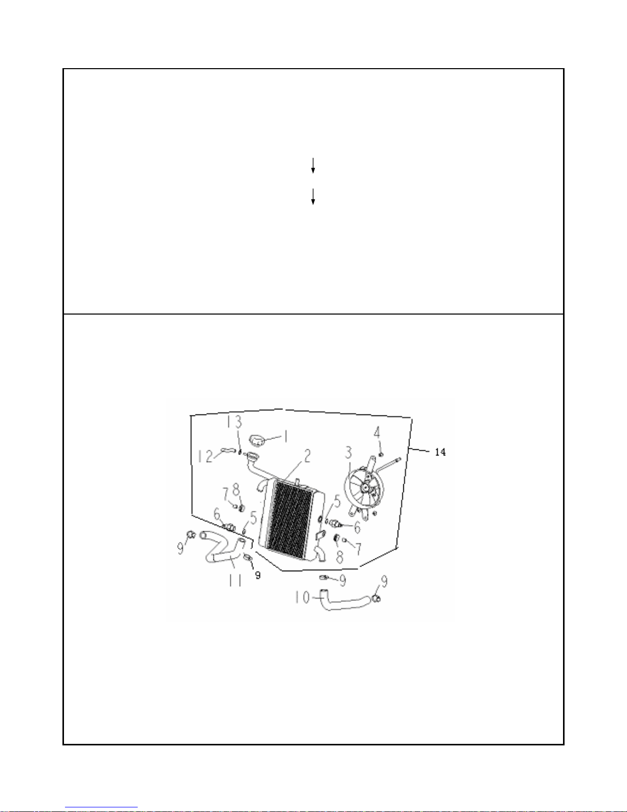
R a d i a t o r a s s e m b l y
D i s a s s e m b l y
D i s a s s e m b l yD i s a s s e m b l y
D i s a s s e m b l y ::::
Circlip(9)
Intake pipe of water pump(11)/Outtake pipe of water pump(10)
Radiator COMP(14)
Assembly
AssemblyAssembly
Assembly::::opposite of the steps of disassembly。
22
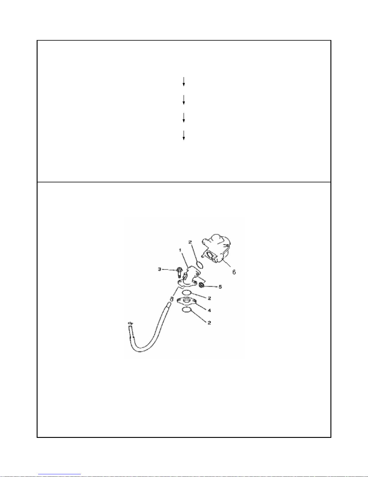
C a r b u r e t o r i n t a k e p i p e a s s e m b l y
Disassembly
DisassemblyDisassembly
Disassembly::::
Nut(5)
O ring(2)
Carburetor COMP(6)
Bolt(3)
Bakelite washer(4)/O ring(2)
Assembly
AssemblyAssembly
Assembly::::opposite of the steps of disassembly.
23
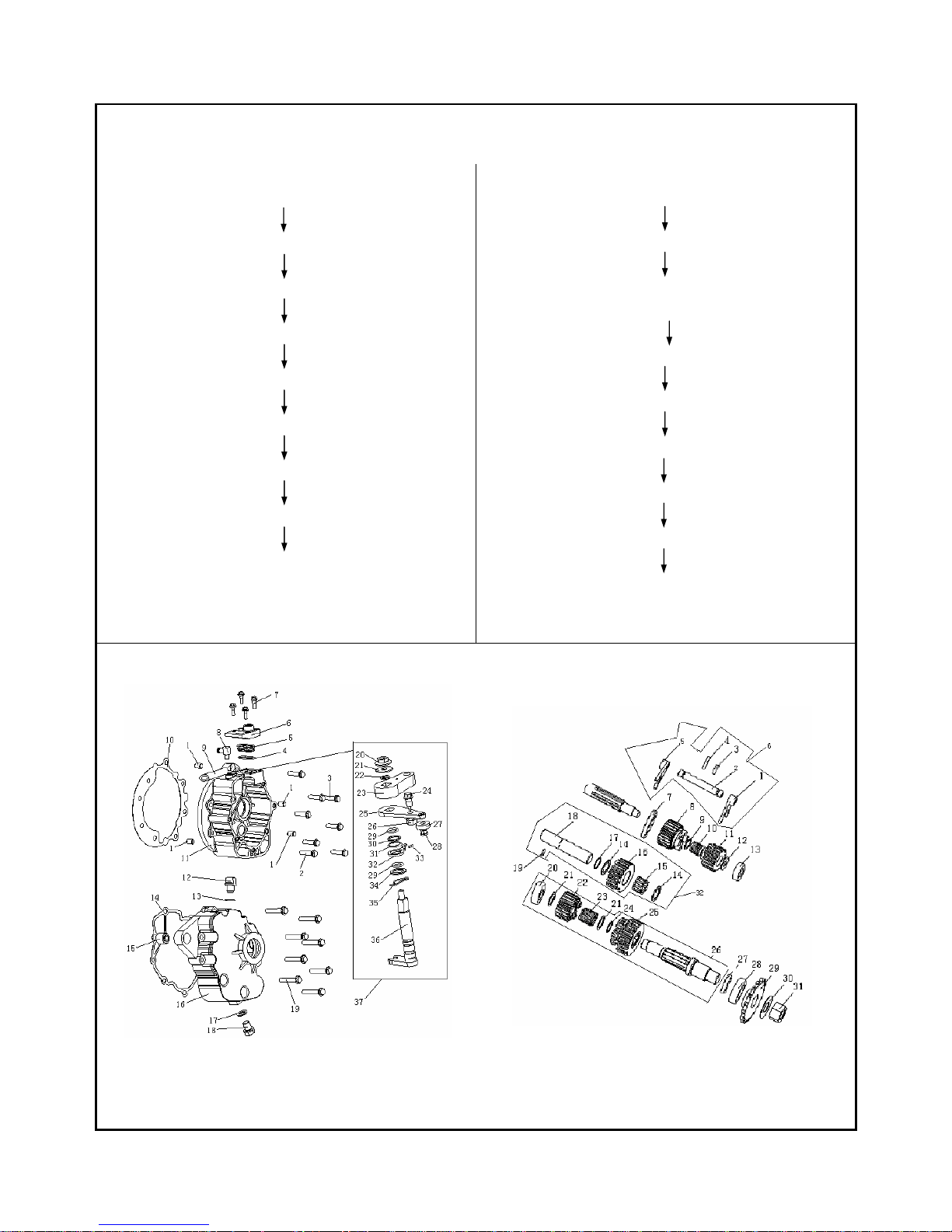
G e a r c a s e / R e v e r s e g e a r
Disassembly
DisassemblyDisassembly
Disassembly
outtake chain wheel(B29)
Rocker (A23)
Bearing(A26)/Display of gear (A5)/feeler of
gear (A29)
Bolt(A19)
Gear case cover(A6)/Washer(A14)
Reverse gearing drive gear(B6)/Needle bearing
(B10)
Outtake bearing COMP(B26)/Gear bearing comp(B6)
/Drive gear(B8)
Idle wheel comp (B32)
Gear shift bearing(A36)
Assembly
AssemblyAssembly
Assembly
Gear shift bearing(A36)
Idle wheel comp(B32)
Outtake bearing comp(B26)/gear bearing comp(B6)
/Drive gear(B8)
Reverse gearing drive gear(B6)/Needle bearing(B10)
Gear case cover(A6)/washer(A14)
bolt(A19)
bearing seat(A26)/display of gear(A5)/feele
r
of gear (A29)
Rocker(A23)
Outtake chain wheel(B29)
A B
24
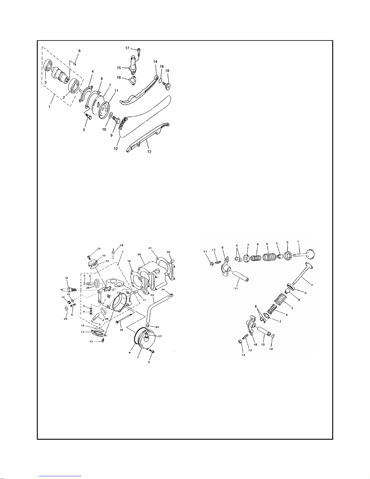
C y l i n d e r h e a d a s s e m b l y
Disassembly :
Timing tensioner(A-15)/Chain wheel cover(B-7)/
Valve cap(B-10、11)
Snap to the“T”mark of the magneto
(in the cylinder head comp, at the TDC of the
compress jotubey)
Breather hose(B-23)/Circlip(B-24)
Chain wheel cover(B-11)/Timing driven chain
wheel(B-7)
Plate of the camshaft(A-4)/Camshaft COMP(A-1)
Cylinder head comp(B-1)
Valve rocker bearing (C-10、11)/valve rocker
(C-9、15)
Clip of valve(C-6)/Spring seat of valve(C-7)/
Spring of intake and outtake valve (C-4、5)
(tied tools T04)
Intake and outtake valve(C-1、2)
Valve seal comp(C-6)
*valve pipe(B-2)
Cylinder head
*Disassemble the valve pipe when it is essential
Assembly
AssemblyAssembly
Assembly::::
Cylinder head
Valve pipe(B-2)
Valve seal comp(C-6)
Intake and outtake valve(C-1、2)
Clip of valve(C-6)/Spring seat of valve(C-7)/
Spring of intake and outtake valve (C-4、5)
(tied tools T04)
Adjust cover of valve clearance(B-10、11)/
Valve rocker bearing(C-10、11)valve rocker(C-9、15)
Cylinder head(B-1)
Plate of the camshaft(A-4)/ Camshaft COMP(A-1)
Chain wheel cover(B-11)/ Timing driven chain
wheel(B-7)
Breather hose(B-23)/ Circlip(B-24)
Snap to the“T”mark of the magneto
(in the cylinder head comp, at the TDC of the
compress jotubey)
Timing tensioner(A-15)/Chain wheel cover(B-7)/
Valve cap(B-10、11)
Adjust the interval of valve
(
The interval of intake valve is 0.03~0.05mm, the interval of
outtake valve is 0.05~0.06m)
Torque value
Torque valueTorque value
Torque value::::
1.Fixed bolt of cylinder cover 10~12 N·m
2.The tensioner bolt and fixed bolt 10~12 N·m
3.Lock nut of wheel fixer 22~25 N·m
4.Trachea 10~12 N·m
25
Istructions
IstructionsIstructions
Istructions::::
1.The valve should be rubbed evenly before assembly,the
rubbing lines of the valve and valve seat should be even
after rubbing.
2.when assembling the valve,check the vale pole and adda
little fixing oil on it,the ploe should roll agilely without
any retardarce in the pipe.
3.make sure that the close end is gadarene when the
spring ofvalve is assembled.
4.test if the valve leaks,pour coal oil into the outtake
pipe,line of the vale should not have leak phenomenon。
5.the tensioner of shain shoul flex freely,remember
that there should be suitable clearance between the chain
and the chain wheel.
Diagram A
Diagram B Disgram C

26
P i s t o n a s s e m b l y
Disassembly:
The first ring
The second ring
Washer of oil ring (1)
washer of oil ring(2)
gasket of oil ring
piston
Assembly::::
Opposite to the steps of disassembly
Instructions::::
1、The first one is white,the second is black.
2、The surfaces whit letters of the first and second rings
should be upttubed.
3、the positions of the two rings can not be changed.
4、Letter“IN”faces to the intake valve,the hatches of the first ring and washer of oil ring(1)
faces to the outtake valve,he hatches of the second ring and washer of oil ring(2)
faces to the intake valve.
5、It is 80-1000 between the gaps of spring cilclip and channel slot.
position standard
The first ring 0.1~0.2mm
The second ring 0.1~0.2mm
clearance of hatch during
working
Washer of oil ring 0.3~0.4mm
The first ring 0.013~0.045mm
The clearance between
piston ring and the ring slot
The second ring 0.013~0.045mm
 Loading...