

KEEWAY ARN125, ARN150 Service And Maintenance Manual
1
Scooter Service and Maintenance Manual
ARN125/150
C o p y r i g h t :
K E E WAY I N T E R N AT I O N A L D E V E L O P M E N T C O . , LT D .
FEB.2006

2
If you have any problems can not fnd the solution in this manual, please
fell free to contact with:
KEEWAY INTERNATIONAL DEVELOPMENT CO.,LTD
2000 SZENTENDRE U.8 KOZUZO. HUNGARY
TEL:0036-26-500005
FAX:0036-26-312034
EMAI: info@keewaymotor.com
Our engineer are very glad to give you the necessary assistance and
help.

3
CONTENTS
Perface
A General knowledge
1. Basic term-----engine
2. Engine type—4 STROKE ENGINE,WORK CYCLES/ILLUSTRATIONS.
3. Safety for repair shop
4. Electric safety
B PRODUCT
1. Technical parameter
2. Special service tools
3. Engine and transmission system
a) Specified torque volume
b) Small but vital parts
c) Non-directional accessory-engine part
d) Engine removal and installation
e) ------ Cowling assembly
------Cylinder head assembly
-------Sub-cylinder shaft retainer assembly
----- Piston assembly
------Left crankcase cover assembly
---------Right crankcase cover assembly
--------Right crankcase
---Left crankcase parts assembly
----Crankcase assembly
----Transmission case
----Driven wheel disc clutch assembly
---- Kick starter shaft subassembly, transition gear shaft subassembly installation
---Driver wheel disc part assembly
---Exceeding clutch assembly
f) ---Power transfer chart
g) Lubricating system
h) Engine valve clearance setting
i) Cyliner pressure testing
j) Important standard dimension----engine
4. Oil----fuel system
--- Carburetor
----Carburetor removal/installation/
adjustment
5. Scooter body installation
6. Fixing torque---scooter body part
a) Front wheel assy.

4
b) Rear wheel assy.
c) Muffler assy.
d) Front fork assy.
e) Front shock absorber assy.
f) Disc brake system
g) Points for motorcycle installation
h) Important dimension for scooter body
6. Electric work/electric
a) Magneto
b) Circuit diagram
c) Electronic ignition part test
d) Battery charge circuit and testing process for battery charge
e) Signal system circuit diagram
f) Various bulbs removal and installation
g) Inspection process for electronic accessories
h) Main electric accessories specification
i) Important electric parameters
C else
7. Inspection/inspection points before using
8. Periodical service
9. Permission and forbiddance
10. Safe driving
11. Fault inspection
5
A
GENERAL
INFORMATION
6
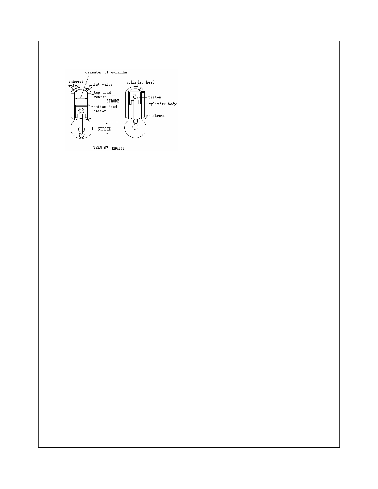
1 .... B A S I C T E R M S O F EN G I N E
A. DEAD CENTER
DEAD CENTER IS THE TWO LIMITED
POINTS, WHERE PISTON MOVES UP
AND DOWN IN LINE.
TOP DEAD CENTER-WHICH IS FARTHEST
AWAY FROM THE ROTATION CENTER OF
CRANKSHAFT.
BOTTOM DEAD CENTER-WHICH IS NEAREST
AWAY FROM THE ROTATION CENTER OF
CRANKSHAFT.
B.
B.B.
B. CYLINDER DIAMETER
CYLINDER DIAMETER CYLINDER DIAMETER
CYLINDER DIAMETER
INNDRE DIAMETER OF CYLINDER IS CALLED CYLINDER DIAMETER.
C.
C.C.
C. JOURNEY
JOURNEY JOURNEY
JOURNEY
JOURNEY IS THE DISTANCE THAT PISTON
TRAVELS. WE USUALLY CALL ONE JOURNEY FROM
TOP DEAD CENTER TO BOTTOM DEAD CENTER.
D. WORKING CAPACITY OF THE CYLINDER
THE SPACE VOLUME OF PISTON WORKING
PATH, WHICH PISTON MOVES FROM TOP DEAD
CENTER TO BOTTOM DEAD CENTER IS CALLED
WORKING CAPACITY OF CYLINDER. USUALLY THE UNIT OF CYLINDER WORKING
VOLUME IS CC(CM³), SUCH AS 75CC, 125CC, WHICH IS DIFFERENT FOR WITH DIFFERENT
ENGINE MODEL.
E. TORQUE
TORQUE IS THE FORCE OF WHIRLING OR ROTATING.
WHEN WE LOOSEN OR SCREW NUTS/ SCREWS, WE HAVE
PUT TORQUE ON IT.
IN ORDER TO DRIVE THE WHEELS, THE ENGINE PUT TORQUE,
WHICH MAY STRENGTHEN LARGER FORCE ON WHEELS
WHEN CLIMBING SLOPE.
THE TORQUE IS EQUAL THAT THE FORCE MULTIPLIES THE
7
ARM OF FORCE.
THE UNIT OF TORQUE IS KILOGRAM POWER-METER.
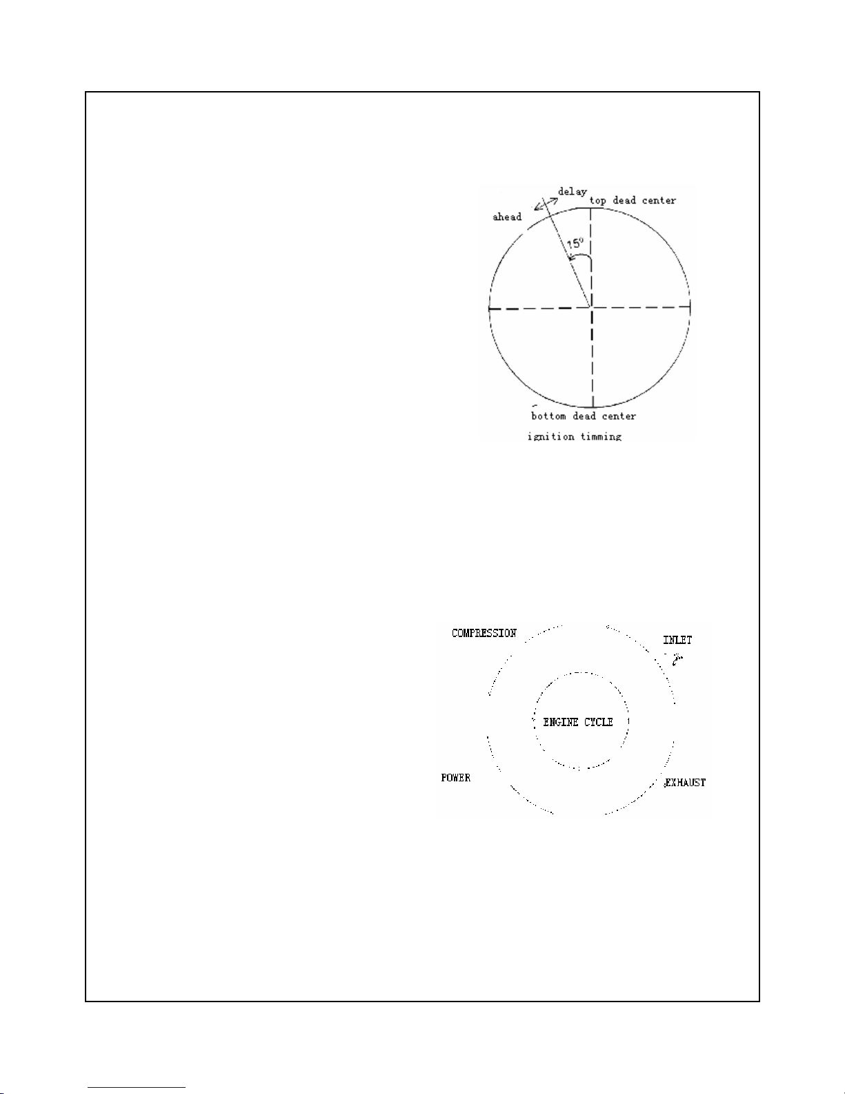
F. IGNITION TIMING
IN ORDER TO CONTROL THE BURNING OF
FIRE CHAMBER,, IGNITION IS TIMING.
THE IGNITION TIMING OF ENGINE QJ162FMJ
CHANGES AS FOLLOW:
WHEN ‘F’ IS 1400RMP, TOP DEAD CENTER
ADVANCES 15°..
WHEN “II” IS 4000RMP, THE TOP DEAD CENTER
ADVANCES 35°.
ENGINE CYCLE
ANY FOUR-STROKE GASOLINE ENGINE
HAS
FOUR STROKES, WHICH CONSIST OF ONE
WHOLE
OF CYCLE.
1.INLET: AIR AND MIXTURED AIR OF OIL
ARE ABSORBED INTO INLET CYLINDER.
2.COMPRESSION: MIXTURED AIR IS
COMPRESSED IN
THE CYLINDER.
3.POWER: WHEN IGNITING ENGINE, GAS
BURNS
AND EXPANDS, AND PUSH THE PISTON
MOVING
DOWN, CONNECTING ROD DIRVES ALONG
CRANKSHAFT AND OUTPUT MECHANICAL
ENERGY.
4.EXHAUST: THE EXHAUST GAS IS
EXPELLED FROM
CYLINDER.
8
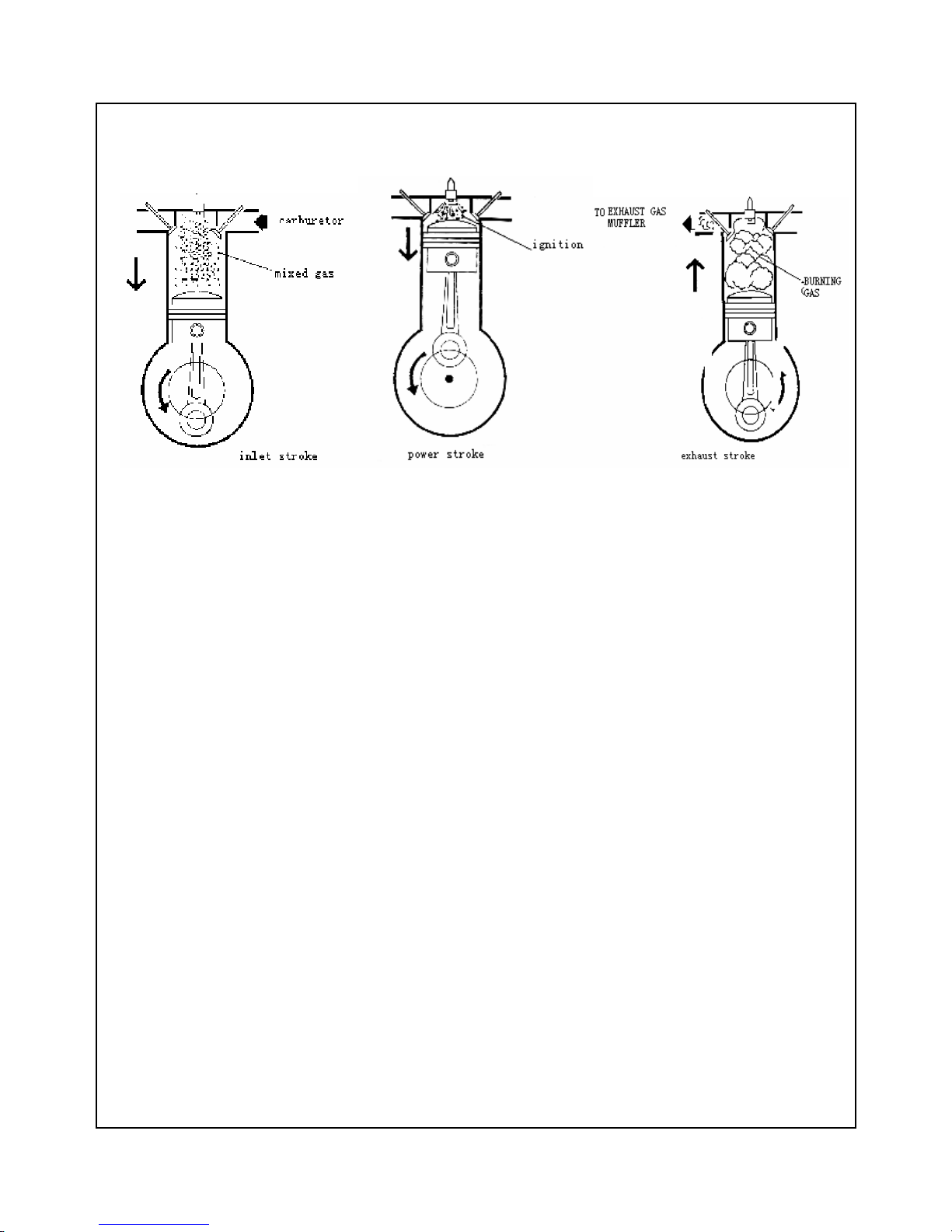
2....4-STROKE ENGINE CYCLE
A::::INLET STROKE
1、CRANKSHAFT TURNS ANTICLOCKWISE.
2、CRANKSHAFT BRINGS ALONG PISTON TO MOVE THROUGH CONNECTING ROD.
3、WHEN PISTON TRAVES FROM TOP DEAD CENTER TO BOTTOM DEAD CENTER, INLET
PORT OPENS, MIXED GAS GOES INTO CYLINDER.
B. COMPRESSION STROKE
1. CRANKSHAFT REVOLVES CONTINUALLY, BRING ALONG THE PISTON TO MOVE FROM
TOP DEAD CENTER TO BOTTOM DEAD CENTER THROUGH CONNECTING ROD.
2. MIXTURE AIR IS COMPRESSED INTO A NARROW SPACE BETWEEN CYLINDER HEAD
AND PISTON HEAD, WHICH IS CALLED BURNING CHAMBER.
CCCC:::: POWER STROKE
POWER STROKE POWER STROKE
POWER STROKE
1. SPARK PLUG INNITES COMPRESSED MIXED GAS OF AIR AND FUEL.
2. Burning of mixed gas of air and fuel results in sudden change of temperature
and pressure in Burning chamber, and then burning gas expands, the power acted on piston
push piston to move down. The power acted on piston transfers to crankshaft through
connecting rod, which leads that crankshaft moves more fastly. Expansion of burning mixed
gas provides enough power.
D: EXHAUST STROKE
D: EXHAUST STROKE D: EXHAUST STROKE
D: EXHAUST STROKE
b) When burning gas pushes piston continually to bottom, exhaust port opens.
c) For inertia crankshaft push piston to Move toward cyliner head.
d) As piston moves toward cylinder head, burning gas is excelled from exhaust port. When piston
travels to top end, exhaust port is shut off.
9
3 .... S E R V I C E W O R K S H O P S A F E T Y
WARNING
Don’t use the tool, which is damaged or easy to be
emerged, that may hurt you.
WARNING
Gasoline is flammable, and may explode in
some condition. Please never get it near smoke
or spark.
WARNING
Please often keep ground tidy and clear. Never
leak fuel on ground to avoid skidding and
damage.
WARNING
Never totate engine in close or bad ventilated
room, for exhaust contains poison gas.
WARNING
Please never clean brake hub, brake shoe and so
on with dry brush or compressed air to avoid
inhaling asbestos fibre, which may results in
cancer or other breath system disease.
WARNING
There is vitriol in storage battery, please protect
your eyes, skin and clothes. If touching vitriol
inadvertently, please wash it with water and see
doctor.
WARNING
Keep close privity with your colleague to ensure
safety.
WARNING
Please never touch brake fluid with your eyes,
otherwise wash it with water and see doctor.
Never touch brake fluid with hands for some
long time.
Never splash brake fluid on the surfaces of oil
pait parts and rubber accessories.
Never use superfluous fluid, which is exposed
in air, remaining fluid has absorbed moisture
from air, which may damage its speciality.
S E R V I C E R U L E S
1. Please use QianJiang genuine parts, and use recommended lubricant in pointed place.
2. Use special or universal tools.
3. When reassembling, use new sealed washer, O-ring, oil seal, clip, cottern pin etc.
4. Use metric bolt and nut.
5. When assembling bolt and nut, firstly tighten big diameter or central bolt and nut. Secondly tighten bolt
and nut with diagonal.
6. After assembly, check bolts and nuts tightening degree with torque wrench check if parts can move
freely.
7. Before measuring, oil and dirt should be removed; when assembly, make parts lubricated by
lubrication.
8. When parts are removed and need be reserved for a long time, please smear some lubrication on the
surface so that it is rusted and with dust deposition.
10
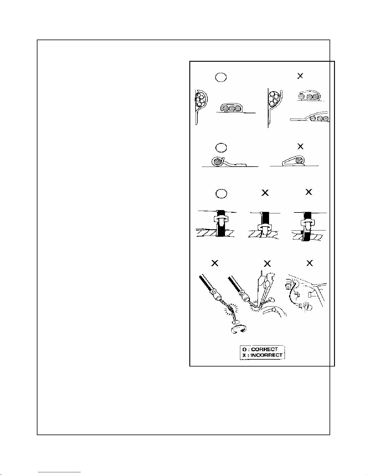
4 . E L E C T R I C S A F E T Y
a) The relaxation of calbe is hidden trouble;
so remember to clamp each calbe to
ensure safety.
b) Don’t bend cable nip toward welding
point.
c) Band cable on oppointed position.
d) Never lay cable in the bottom of frame
or in needle angle position.
e) Never lay calbe in the end of bolts or
nuts.
f) Keep calbe away from hot source part
or some position where calbe may be
clipped when moving.
g) Lay cable along handlebar, don’t pull it
too tight or too loose, and never terrer
with other parts when ratoating in any
position.
h) Lay calbe smooth, never distort or tie it.
i) Before connecting joint, inspect if joint
is damaged and joint is stretched.
j) If calbe is layed in needle angle or
turning position, protect calbe with
adhesive tape or tube.
k) After repairing, band up it with adhesive
tape.
l) Never keep contolling calbe bended or
distorted. If controlling calbe is
damaged, you may lose stable.
11
B
PRODUCT

12
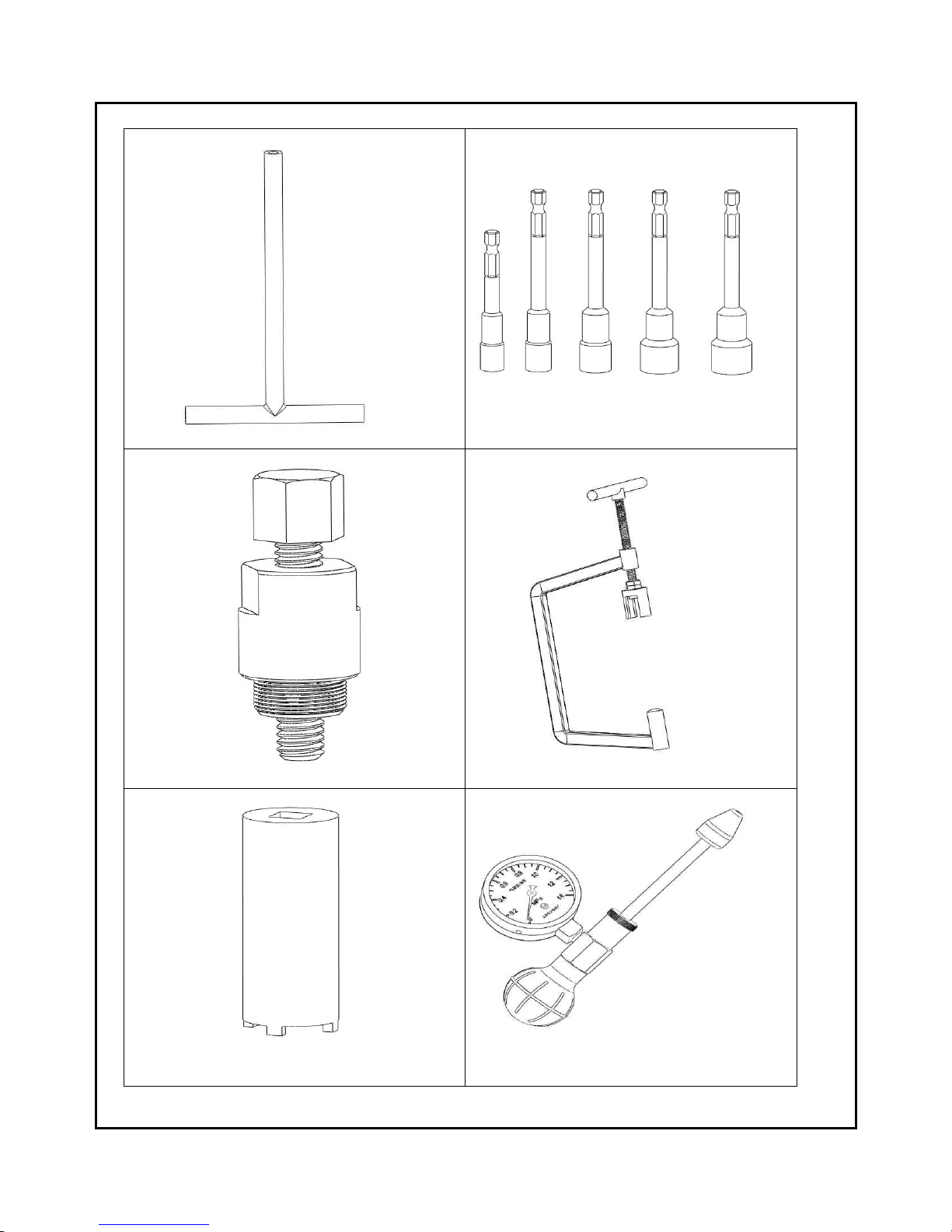
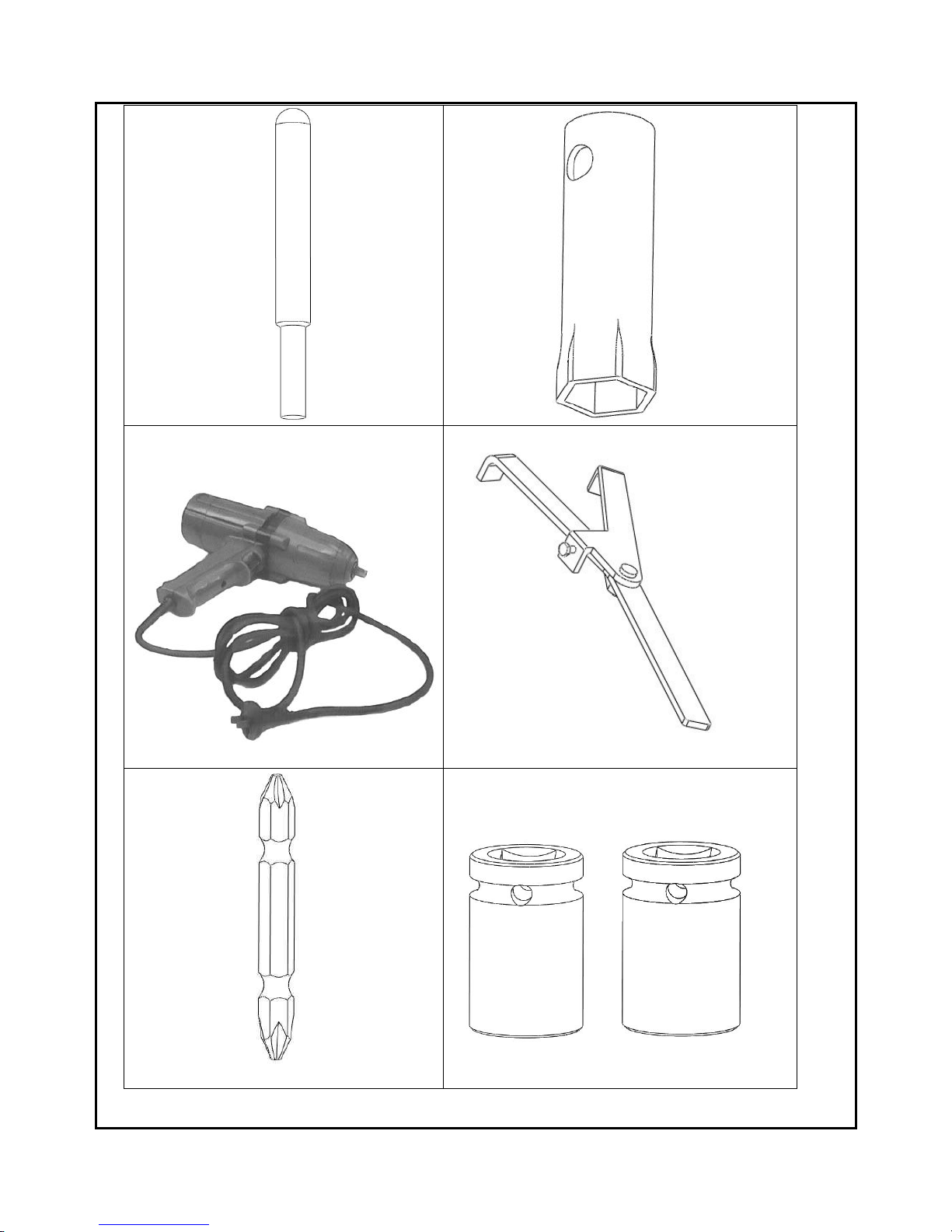
1 . S P E C I A L T O O L S L I S T
NECESSARY TOOLS TO DISASSEMBLE AND INSTALL MOTORCYCLE ENGINE AS FOLLOWS:
CODE
TOOLS CODE PURPOSE
1
2
3
4
5
6
7
8
9
10
11
12
T01
T02
T03
T04
T05
T06
T07
T08
T09
T10
T11
T12
“T”SHAPE GUIE CYLINDER
GUIDE CYLINDER TOOLS(8,10,12,13)
SCREWED ROD FOR FLY WHEEL DISASSEMBLAGE
TOOLS TO DISASSEMBLE VALVE SPRING
DISASSEMBLING TOOLS FOR OIL DRAINAGE
CYLINDER PRESSURE GAUGE
DISASSEMBLING TOOL FOR PISTON PIN
SOCKET FOR DISMOUNTING SPARK PLUGS
ELECTRIC TOOL FOR DISASSEMBLING LOCKING BOLT OF
FLY WHEEL
CULTCH CLAMP
DISASSEMBLING SCREW TOOL
GUIDE CYLINDER (17,18)
13
○1
○
2
○3
○
4
○
5
○
6
14
○
7
○
8
○
9
○
10
○
11
○
12

15
3 .... E N G I N E A N D T R A N S I M I S S I O N S Y S T E M ( A .... S P E C I A L T O R Q U E )
The following table liss torques of some locking accessories/fixers, which you can refer to in assembly.
NO.
NA ME QTY TORQUE
1
2
3
4
5
6
7
8
9
10
11
12
13
14
15
16
17
18
19
20
21
22
23
24
25
26
27
28
29
30
31
32
33
34
35
36
37
38
39
40
Tapping screw for fan snail cover assy.
Lucknut for fan snail cover assy.
Tapping screw for up and down guide air cover
Lucknut for up and down guide air cover
Tapping screw and nut for ventilating air chamber of cylinder head
covr
Locknut for cylinder head cover
Locknut for double head blot on cam fixing
holder
Locknut for atmolysis chain pulling rod
Lucknut for atmolysis chain adjustor
Lucknut for cylinder head
Locknut for cylinder observing oil read
Spark plug
Double head bolt for cylinder head inlet port
Double head bolt ofr cylinder head exhaust port
Lucknut for carburetor joint
Lucknut for cooling impeller of fan
Locknut for flywheel
Locknut for magnet stator coil
Locknut for magnet motor trigger
Locknut for right crankcase cover
Oil filter cover cap
Locknut for oil pump seperating board
Locknut for oil pump sprocket
Locknut for oil pump
Locknut for oil pump cover
Locknut for super-clutch
Locknut for super clutch outside
Locknut for right crankcase
Double head bolt for left and right crankcase
Fixing bolt for motro
Locknut for left crankcase cover and line coil
Tapping screw for ventilating guide board of left
crankcase cover
Locknut for driver disc
Locknut for driven disc
Locknut for driven disc clutch
Locknut for press-board of kick starter
Locknut for transmission case cover
Locknut for flowing oil hole of transmission case
Locknut for flowing oil hole of left crank.
Locknut for position shaft of left crank
2
2
3
1
3
4
4
1
2
2
1
1
2
2
2
4
1
2
2
9
1
2
1
2
1
1
3
2
4
2
11
4
1
1
1
1
5
2
1
1
1-3N••M
10-12N•M
1-3N••M
10-12N•M
1-3N••M
10-12N•M
22-25N•M
10-12N•M
10-12N•M
10-12N•M
10-12N•M
10-15 N•M
10-12N•M
10-12N•
M
10-12N•M
10-12N•M
45-55N•M
6-8N•M
10-12N•M
10-12N•M
55-60N•M
10-12N•M
8-10N•M
10-12N•M
1-3N••M
35-40N•M
10-12N•M
10-12N•M
22-25N•M
10-12N•M
10-12N•M
3-6N•M
45-55N•M
45-55N•M
55-60N•M
10-12N•M
10-12N•M
22-25N•M
40-45N•M
22-25N•M

16
b . I M P O R TA N T PA R T S
The following is detail information of vital position pin, O-ring, bearing, pin shaft and gasket of
ENGINE/UNDERPAN:
POSITION PIN-14NOS.
S.NO.
Size (mm) Qty. Description Location
1 10Фx16 2
Camshaft fixing seat and
cylinder head
Engine
2 10Фx16 2
Cylinder head and cylinder head
Engine
3 10Фx16 2 Crankcase and cylinder body Engine
4 10Фx16 2
Left and right crankcase
Engine
5 8Фx14 2 Left crankcase and gearbox Engine
6 10Фx16 2 Left crankcase and left cover Engine
7 8Фx14 2
Rignt crankcase and right
cover
Engine
O-ring-7NOS.
S.NO.
Size (mm) Qty. Description Location
1 9Фx1.6 2 Inlet and exhast valve pipe Engine
2 13.7Фx1.5 1 Atmolysis chain pulling lever Engine
3 9.5Фx1.5 1 Atmolysis chain adjustor Engine
4 18Фx3 1 Oil gauge Engine
5 30Фx3 1 Filter spring cap Engine
6 26502470 1 Starting moto Engine
Oil seal- 4NOS.
S.NO.
Size (mm) Qty. Description Location
1 27x42x7 1
Output shaft---gearbox cover
Engine
2 20x32x6 1
Output shaft—left crankcase
Engine
3 19.8x30x7 1
Crank—left crankcase
Engine
4 19.8x30x7 1
Crank—right cover
Engine

17
BEARING- 13NOS
S.NO.
Code Qty. Description Location
1
6004
1
Output shaft—gearbox cover
Engine
2
6201
1
Middle shaft—gearbox cover
Engine
3
6301
1
Output shaft—gearbox cover
Engine
4
6203
1
Output shaft—left case
Engine
5
6202
1
Middle shaft—left case
Engine
6
6204
1
Output shaft—left case
Engine
7
TM-SCO7A87
1
Left crank—left case
Engine
8
TM-SCD5ASSCS12
1
Right crank—right case
Engine
8
K28x33x14
1
Crank pin—crank connecting big rod
Engine
9
K28x32x17
1
Clutch hub—cluch gear
Engine
10
6902NSE28 x15x7
1
Driven disc—output shaft
Engine
11
HK20 x29x18RS
1
Driven disc—output shaft
Engine
12
6002
2
Camshaft—atmolysis shaft fixing holer
Engine
PINSHAFT- 2NOS
S.NO.
Size (mm) Qty. Description Location
1 5Фx6 1
Super clutch
Engine
2 4Фx6.5 1
Oil pump
Engine
GASKET- 7NOS
S.NO.
Gasket Type Qty. Location
1
Cyliner head cover Rubber endurable against oil
1 Engine
2
Cylinder head Steel
1 Engine
3
Cylindr body
Asbestos rubber endurable
against oil
1 Engine
4
Crankcase Endurable oil asbestos rubber
1 Engine
5
Right crankcase cover Endurable oil asbestos rubber
1 Engine
6
Left crankcase cover Endurable oil asbestos rubber
1 Engine
7
Atmolysis chain adjuster Endurable oil asbestos rubber
1 Engine

18
Shifting gears inforamtion
Gear down
ratio
Gear Gear qty. Gear QTY.
2.8 A
1
15 A
2
42
3.077 B
1
13 B
2
40
GEAR INFORMATION
NO. GEAR QTY. POSITION
1
Kick starter gear
38 ENGINE
2
Kick starter transition
small gear
13
ENGINE
3
Kixk starter transition big
gear
49
ENGINE
4
Crank kick starter driven
gear
20
ENGINE
5
Starting motor drvie gear
9
ENGINE
6
Electricity starter
transition gear
54/13
ENGINE
7
Clutch gear
52
ENGINE
SPROCKET INFORMATION
No.
No.No.
No. Sprocket wheel
Sprocket wheelSprocket wheel
Sprocket wheel
QTY. POSITION
1
Right crank oil pump driver
sprocket wheel
17 ENGINE
2 Oil pump sprocket wheel
19 ENGINE
3
Left crank atmolysis shaft
driver sprocket
17
ENGINE
4 Atmolysis shaft sprocket
34 ENGINE
CHAIN INFORMATION
NO. CHAIN NODE POSITION
1 ATMOLYSIS SHAFT CHAIN 90 ENGINE
2 OIL PUMP CHAIN 42 ENGINE

19
c . S PA R E PA R T S O F E N G I N E
Please read the following instruction carefully, and ensure spare parts in right position. Otherwise engine
cannot perform.
1. All marks of the following parts should be towards combined surface of left crankcase and
transmission case:Output shaft of left crankcase, middle shaft, output shaft bering
6203,6202,6204, and output shaft of transmission case, middle shaft, output shaft bearing
6004,6002,6301.
2. The side of driven wheel disc rolling needle bearing with mark needs to be toward seeable direction,
and the side of ball bearing with mark needs to be towards clip.
3. The convex prick side of the gasket between driver wheel disc and driven wheel disc is towards
locknut.
4. The side of kick-starter gear and transition gear with mark is towards left cover.
5. Chain guiding groove is towards chain, and column rod of chain guiding part is not higher than
the surface of cylinder.
6. White piston circle is the first one, black piston circle is the second one; hatches
of circle 1 and circle 3 are towards exhaust port, hatches of circle 2 and circle
4 are towards inlet port; the side with English letter is towards the top of piston.
7. “IN” mark on piston is towards carburetor side.
8. Valve spring (dense end) is towards valve pipe.
9. The side of camshaft bearing 6002 with mark is towards cam.
10. The side of oil pump with letters is towards outside.
The side of left and right crankcase bush with “W” mark is towards the reverse of combined surface
of left and right crankcase
20
d . E N G I E N R E M O VA L A N D I N S TA L L AT I O N
REMOVAL INSTALLATION
Guiding-wind cover/fan cover/carburetor left crankcase assy./gearbox assy.
Left crankcase cover/gasket/piston pin gearbox
Outside part of left crankcase crankshaft/left and right crank motor
Chain adjustor /cylinder head cover oil pump/super-clutch/electric start transition gear
Camshaft holder/cam right crankcase cover/oil filter/oil gauge
Cylinder cover/gasket/pin coil/flywheel/fan impeller
Cylinder/gasket/pin piston/piston pin/spring clip
Spring clip/piston pin/piston cylinder/gasket/pin
fan impeller/flywheel/coil cylinder cover/gasket/pin
Right crankcase cover/oil filter/oil gauge cam/camshaft supporter
Right crankcase outside chain adjustor/cylinder head cover
Start motor/left and right crankcase/crank left crankcase outside assy.
Gearbox left crankcase cover/gasket/pin
Left crankcase/gearbox cover guiding-wind cover/fan cover/carburetor
NOTICE:
a) Before installation, wash engine parts, and then lubricate engine, refer to recommended torque volume to lock
screw.
b) Pay special attention to single direction fixing accessories.
Start and inspect oil road lubricating system after having reinstalled engine.
21
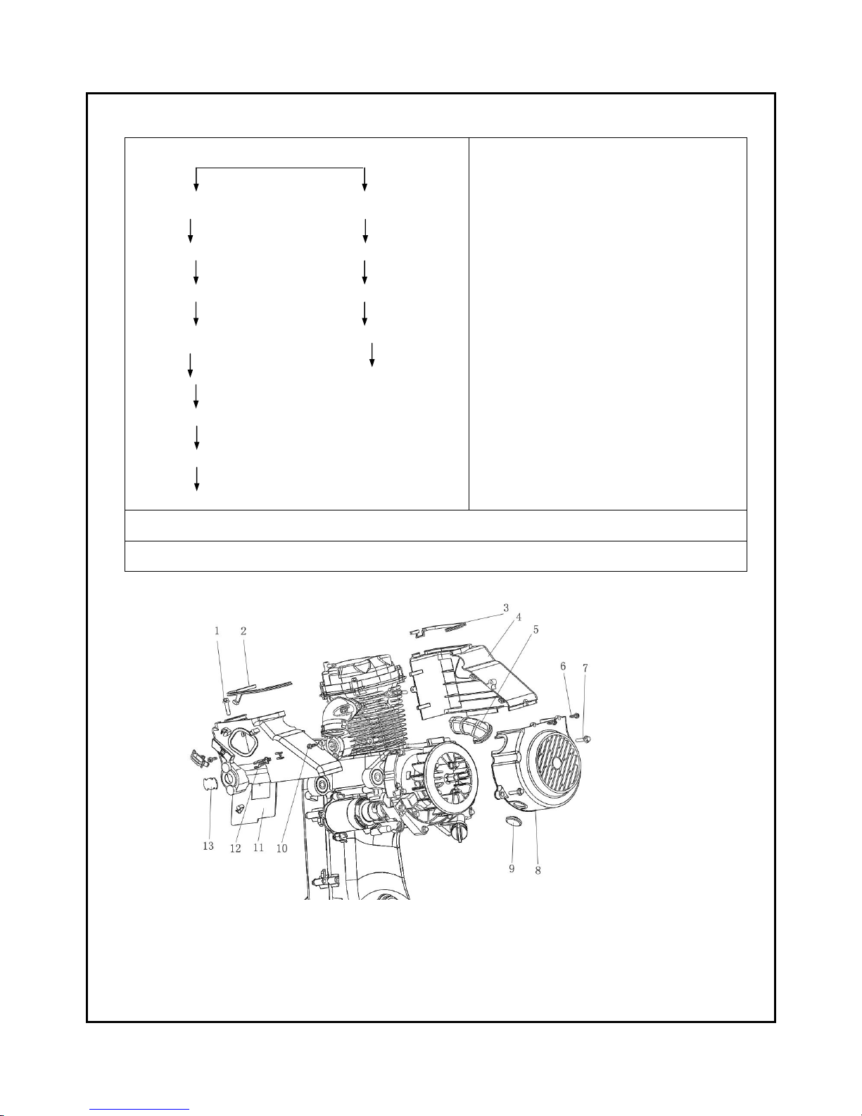
C O W L I N G A S S E MB LY
REMOVAL:
Scrrew (10) screw (6)
Bolt (1) bolt (7)
Top cowling (11) fan whorl cover assy. (8)
Bottom cowling (4) pastern cover (9)
Top cowling seal gasket (2) cooling pipe (5)
Bottom cowling seal gasket (3)
Coil clip (12)
Pastern cover (13)
Whorl cover screw(6) 2N.M
Whorl cover bolt (7) 11N.M
Cowling screw (10) 2N.M
Cowling bolt(1) 11N.M
installation::::The installation sequence is essentially the reverse of removal.
Notice: avoid missing cowling seal bar.
22
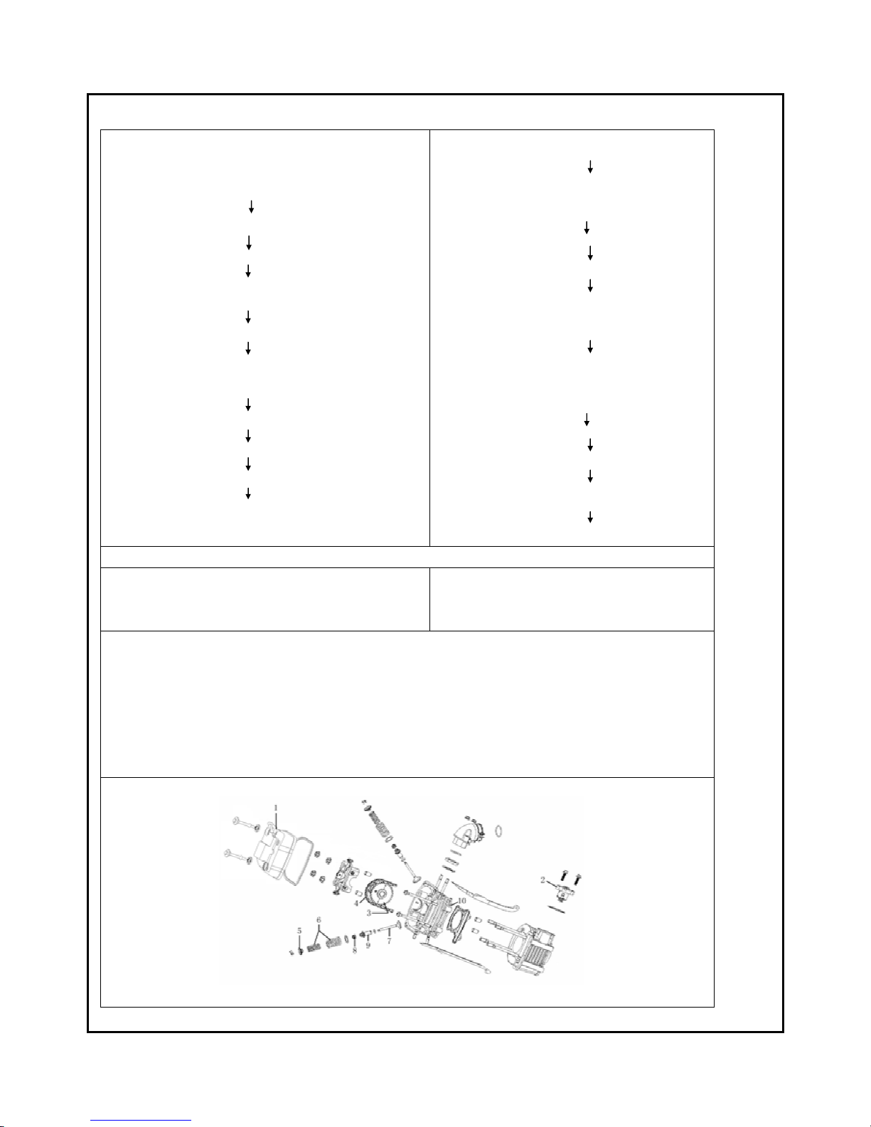
B . c y l i n d e r h e a d i n s t a l l a t io n
REMOVAL
Cylinder head cover (1)/cylinder head cover seal bar
Right against “T” mark on magneto
(in the bottom of exhaust stroke )
timing chain tensioner(2)
atmolysis shaft assy.(3)/atmolysis shaft chain
(4)
(shuf off)
Atmolysis shaft holder assy./Atmolysis shaft fixer assy.
Cylinder head assy.
valve lock clip/valve spring holder(5)/inlet、exhaust
valve spring)
(special tool T04)
inlet valve and exhaust valve(7)
Valve oil seal assy.(8)
Valve pipe(9)
Cylinder head(10)
Installation
Cylinder head
Valve pipe/valve oil seal assy./gasket
Inlet valve and exhaust valve/valve
spring/spring holder/lock clip
Cylinder head assy.
Atmolysis shaft chain/atmolysis shaft
assy.
(mesh)
Atmolysis shaft assy. and atmolysis shaft
fixer assy.
Right against mark “T” on magneto and
correct timing mark on timing gears
(keep timing scale of timing gears on the
same level with joint surface of cylinder
head cover)
Timing chain tensioner(adjust)
Adjust valve clearance
(inlet valve clearance: 0.03~0.05mm,
exhaust valve clearance: 0.05~0.06mm)
Cylinder head cover and seal rubber bar
*Remove it if necessary
TORQUE::::
1. Cylinder head cover fixing bolt 10~12N·M
2. Tension bolt and fixing bolt 10~12 N·M
3. Cam fixer locknut 22~25 N·M
4. Inlet pipe locknut 10~12 N·M
NOTICE::::
1.Skive valve before installing vavle, and shake it, valve and valve seat should be even after
skiving.
2. Daub valve lever with some cream to avoid scratch it, after having installing it, valve lever
should be turned flexibly without block.
3. Be sure to keep dense end of valve spring down

23
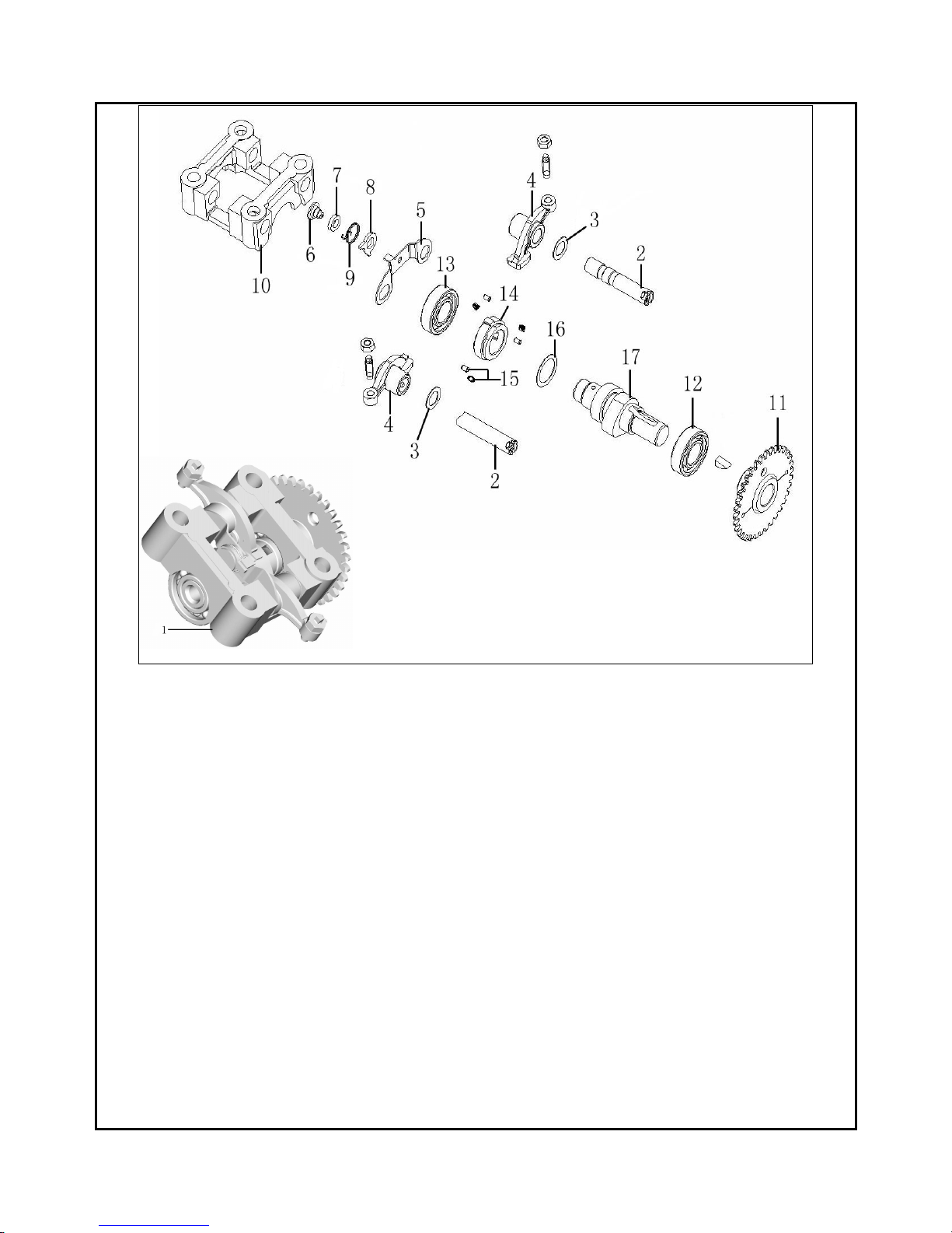
c . AT M O LY S I S S H A F T F I X E R A SS E M B LY
REMOVAL
Atmolysis shaft fixer assy. and atmolysis shaft
assy.
Atmolysis shaft fixer assy.
Rocker arm shaft(2)
Gasket(3)and rocker arm(4)
Stopper board(5)
Axes (6)and bush(7)
Mass (8)and spring(9)
Atmolysis shaft fixer(10)
Atmolysis shaft assy.
Atmolysis shaft sprocket comp.(11)
Atmolysis shaft right bearing(12)and atmolysis
shaft left bearing(13)
Auto reductor outside ring(14)and ball bearing,
spring(15)
Adusting gasket(16)and atmolysis shaft(17)
INSTALLATION
Atmolysis shaft and right bearing(12)
Adjusting gasket(16)
Auto reductor outside ring(14)and ball bearing,
spring(15)
Atmolysis shaft left bearing(13)
Atmolysis shaft sprocket assy.(11)
Atmolysis shaft assy.
Atmolysis shaft fixer(10)
Axes(6), bush(7),mass(8)and spring(9)
Stopper board(5)
Rocker arm(4)and gasket(3)
Rocker arm shaft(2)
Atmolysis shaft fixer assy.
Atmolysis shaft fixer and atmolysis shaft assy.
NOTICE::::
When installing rocker shaft, remember to daub rocker with lubrication, and keep groove of center rocker shaft on
the same level as the hole of rocker seat.
24
25
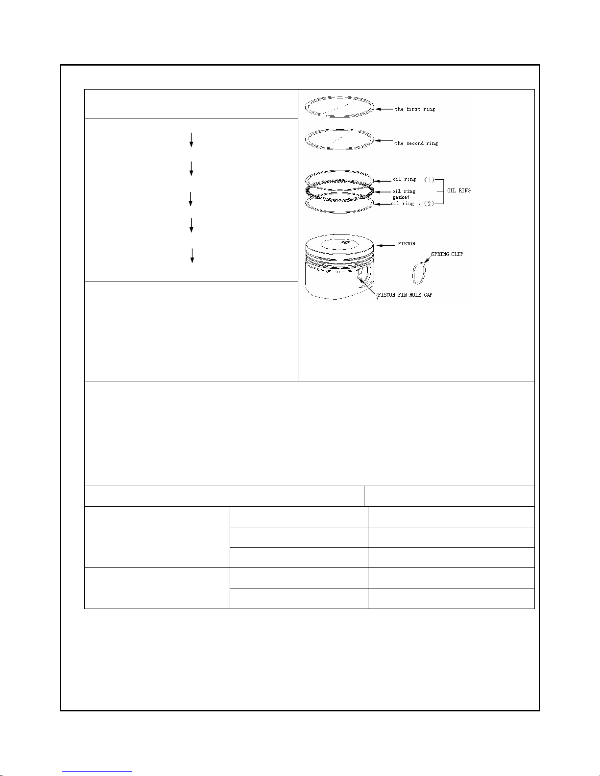
d . P I S T O N I NS TA L L AT I O N
REMOVAL:
The first ring
The second ring
Oil ring slice(一)
Oil ring slice(二)
Oil ring bush
Piston
Installation::::
The installation sequence is essentially the
reverse of removal.
Notice::::
1、 The first ring is white ring, and the second ring is black one.
2、 The sides of the first ring and the second one with English Letters are up.
3、 Never make mistake in positioning the first ring and the second ring
4、 Letter “IN” is towards inlet port, and the first ring is dead against oil ring slice (一).
5、 The gap of spring clip is 80º-100º against the gap of groove.
ITEMS VOLUME
The first ring 0.1~0.2mm
The second ring 0.1~0.2mm
Hatch clearance during working
Oil ring slice 0.3~0.4mm
The first ring 0.013~0.045mm
Clearance between piston ring
and groove
The second ring 0.013~0.045mm
26
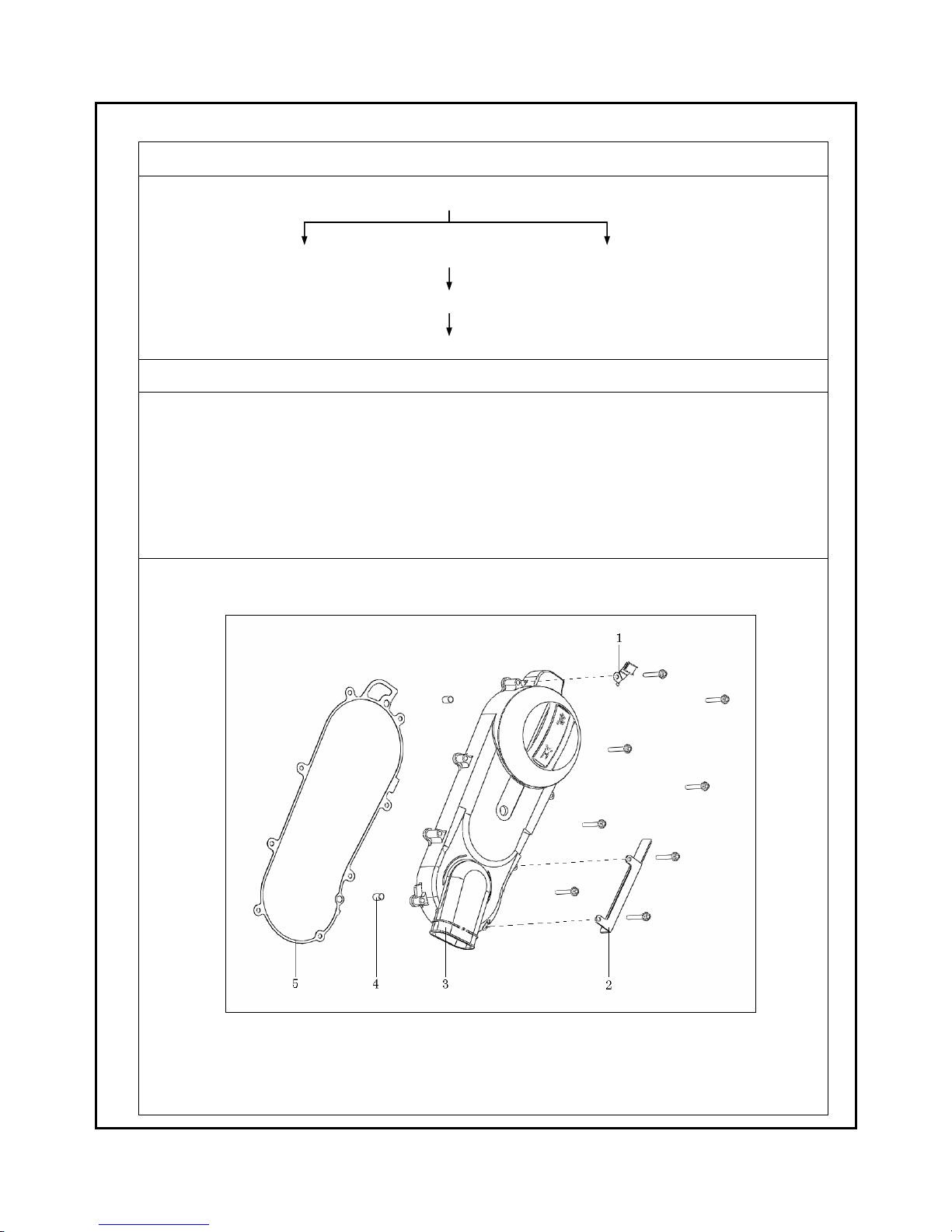
e . L E F T C R A N K C A S E C O V E R I N S TA L L AT I O N
Removal
Left crankcase cover assy.
Clip (1) fender (2)
Left crankcase cover (3)
pin(4)/gasket(5)
The installation sequence is essentially the reverse of removal.
Notice::::
1、 When installing left crankcase cover, tap it to its proper postion with wood hammer or rubber hammer not metal
hammer to avoid damaging the cover.
2、 Position clip (1) and fender (2).
3、 Lock bolts diagonally and for all bolts torque is 10-12N.M.
 Loading...