

Page 1
ThermoSaver
02/12/10
Hot Gas
TM
PRODUCT DATA,
APPLICATION &
INSTALLATION GUIDE
Bulletin K40-THERM-PDI-13
1069130
Supplement to Condensing Unit
Installation & Maintenance Manual
Defrost System
For use on select Air, Remote or
Water-cooled Condensing Units
matched with Low, Medium or High
Prole Evaporators
R22 - R404A 2-30 HP
-30°F to +34°F Room Temperatures
CONTENTS PAGE
Application Guideline..............................
ThermoSaver Operation Cycle...............
Wiring Diagrams.....................................
Installation..............................................
ThermoSaver Control Settings...............
Troubleshooting Guide...........................
Service Parts List...................................
Warranty.................................................
2
3,4
5-7
8
8,9
10
11
BACK
● Provides fast, efcient evaporator
defrosting.
● Complete factory pre-piping of all
controls and valves.
● Utilizes existing liquid line as hot gas
pipe.
● Reduces installation time and provides
maximum savings during operation.
● Ensures maximum compressor
protection using large capacity
suction accumulator and outlet
pressure regulating valve.
Page 2

APPLICATION GUIDELINE
K40-THERM-PDI-13
- 2 -
02/12/10
ThermoSaver Hot Gas Defrost systems provide for a
fast defrost alternative over comparable electric defrost
systems. They can be used on any freezer or cooler
application ranging in room temperatures from –30°F to
34°F, with capacity ranges of 2 – 30HP , available as an
Indoor Air Cooled, Outdoor Air Cooled, Remote or Water
Cooled Condensing unit.
The basic piping, layout and design concept are covered in pages 3 and 4 of this manual. These should be
reviewed rst to understand the refrigerant ow and to
identify the special defrost components used.
Important design points are:
1. Concept is similar to a “three-pipe” hot gas bypass
system yet only uses two pipes (shares the liquid line
and reduces eld piping and labour cost). The main
difference is the third shared pipe does not need to
be oversized. During the initial hot gas cycle Liquid is
fed rst, then a mixture, only at the latter part of the
cycle is it all hot gas. (so high pressure drops are not
realized)
2. The defrost is very fast - less than 10 minutes and
uses pressure controls (not temperature) for termination and fan delay functions. (results in faster
response time)
3. The evaporator used must be included together with
the Condensing Unit (i.e. sold/supplied as a complete system package) as it must be properly selected and piped with the correct defrosting components.
Line runs and sizes need to be reviewed. (keep
within 100 feet) Electric heat drain pans (using time
–delay relay function) are recommended in place of
hot gas loops.
4. This unique defrost system can be used with either
one or multiple evaporators (regardless of the application, freezer or cooler) and all can be defrosted
at once.
5. There does exist added suction pressure drop across
the outlet pressure regulator (CPR) and suction
accumulator so for load calculation purposes do not
undersize (keep adequate added safety margin).
6. Excessive system refrigerant charges (from long
runs, oversized evaps, oversized receivers) must be
avoided. During the latter portion of the defrost cycle
and post defrost refrigeration cycle, refrigerant will
ood back to the suction accumulator. Keeping the
overall system charge low will reduce the amount of
oodback.
To ensure maximum design benets:
1. Review the line runs and sizes (use short and
properly sized liquid lines -do not oversize).
2. Use minimal refrigerant charge. Use only enough to
satisfy the condenser ooding valve (low ambient
control), receiver seal, liquid line and evaporator
charge requirements.
3. Field adjust these ve critical defrost components to
proper initial settings:
(a) Outlet Press Regulator (CPR) Valve- Must be set
to the lowest possible setting (approx 10-15°F
above evap temp design) without compromising post defrost pull-down time. This valve is not
primarily set for motor compressor motor overload
protection, it’s main purpose is to keep a pressure
differential during the defrost .
(b) Defrost Termination Control- Must not be set too
high. Keep to lowest possible setting (as soon as
ice and frost has melted and pressure then starts
to rise). Higher settings result in longer defrosts
(over 10 minutes) and excessive oodback.
(c) Fan Delay Control- Must not be set too low (as
will promote ooding of the evap resulting in increased amount of refrigerant ood back after the
defrost)
(d) Timeclock - Fail safe Time should not be set
greater than 20 minutes. If the defrost is taking too
long then an issue exists with the control settings
or application. (This must be identied and resolved.)
(e) Time –Delay (Hot gas cycle) – Must be set at
least for two minutes (up to 5 min) in order to (i)
pump out all remaining refrigerant in the evaporator and (ii) Pre-heat the drain pan prior to the hot
gas entering the coil. This timer setting must be
longer than the compressor anti-short cycle setting (if equipped)
Important initial set points are covered on pages 8 and 9 in
this manual and must be followed. Further adjustments can
then be made to suit local eld conditions.
Page 3
THERMOSAVER OPERATION
K40-THERM-PDI-13
- 3 -
02/12/10
The ThermoSaver defrost cycle system provides a
quicker defrost period (up to three times faster) over the
conventional electric defrost system. This minimizes the
rise in box temperature during the defrost which reduces
product deterioration and increases the system efciency.
This results in lower running times and reduced energy
costs. When using more than one evaporator on the
same condensing unit, all the evaporators can be defrosted
simultaneously.
All ThermoSaver components are completely factory
installed, pre-piped and pre-wired. An extra third pipe
(hot gas line) is not required.
REFRIGERATION
L M
Suction
Accumulator
Condenser
C
D
Compressor
This signicantly reduces the overall installation time
and cost. Factory installed standard components include
the evaporator distributor nozzle, thermostatic expansion
valve (TXV), liquid line solenoid valve, hot gas solenoid
valve, liquid check valves, three way solenoid valve,
defrost regulating valve, suction accumulator, defrost
termination / fan delay pressure controls and drain pan
heater and timeclock. Room thermostat and suction
lter are optional to be eld installed.
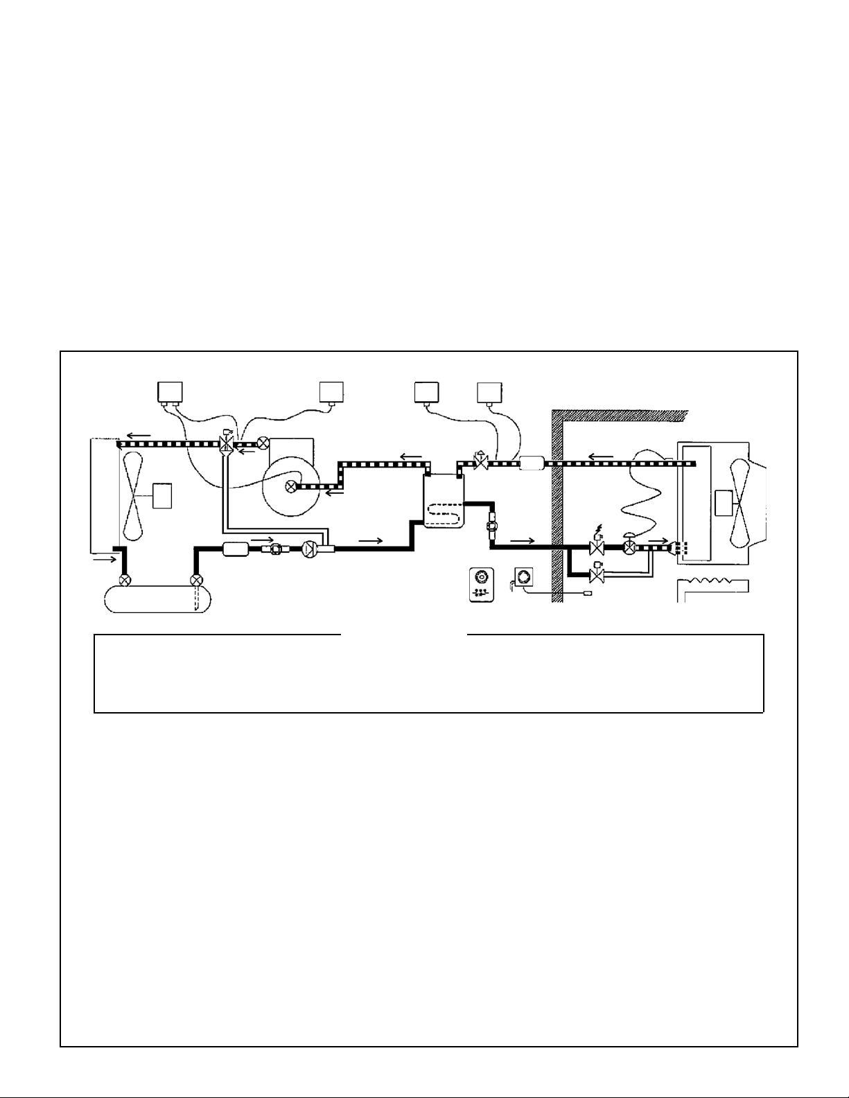
The following diagrams explain the ThermoSaver operation
during both refrigeration and defrost cycles.
N
H
Filter
Evaporator
FB
Boil Out
Drier
Receiver
A - Room Thermostat
B - Liquid Line Solenoid Valve
C - Dual Hi / Lo Pressure Control
D - Three Way Hot Gas Solenoid Valve *
E - Liquid Line Check Valve
* On larger (15 HP & up) systems, a separate N/O and N/C solenoid valve is used in place of 3-way valve
As the box temperature rises, the room thermostat (A)
energizes the liquid line solenoid valve (B). This allows
refrigerant to enter the evaporator, build up pressure,
cause the low pressure control (C) to energize the
compressor contactor and start the compressor. The
compressor’s hot discharge gas is piped out to the
condenser through the de-energized 3-Way valve (D).
or seperate N/O and N/C solenoid valves. The hot
refrigerant gas is condensed by the condenser. The
liquid then ows to the receiver through the opened
check valve (E) and on through the coiled liquid line
within the suction accumulator (this performs the function
as a suction to liquid heat-exchanger). The subcooled
liquid then ows through the liquid line solenoid valve
(energized/open) and on to the TXV (F)
(Thermostatic expansion valve).
E
F - Thermostatic Expansion Valve
H - Defrost Regulating Valve
I - Timeclock
Heat Exchanger
I
LEGEND
The refrigerant is then directed through the distributor
at a lower pressure and ows into the evaporator. The
refrigerant liquid / vapour mixture is then boiled by the
warmer box air from the evaporator fan. The refrigerant
vapour then ows though a defrost regulating valve (H)
preventing a motor overload from high suction pressures
and enters the suction accumulator and on to the compressor.
The cycle continues until the room temperature is satised. This de-energizes the liquid line solenoid, initiating a
pumpdown cycle that reduces the suction pressure to the
cut-out setting on the low pressure control which de-energizes the compressor.
A
J - Drain Pan Heater
K - Hot Gas Solenoid Valve
L - Three Way Hi Pressure Control
M - Defrost Termination Pressure Control
N - Fan Delay Pressure Control
K
J
Page 4
THERMOSAVER OPERATION
K40-THERM-PDI-13
- 4 -
02/12/10
DEFROST
C
Condenser
D
Compressor
L M
Suction
Accumulator
H
N
Evaporator
Filter
FB
Boil Out
Drier
Receiver
A - Room Thermostat
B - Liquid Line Solenoid Valve
C - Dual Hi / Lo Pressure Control
D - Three Way Hot Gas Solenoid Valve*
E - Liquid Line Check Valve
* On larger (15 HP & up) systems, a separate N/O and N/C solenoid valve is used in place of 3-way valve
E
F - Thermostatic Expansion Valve
H - Outlet Pressure Regulator
I - Timeclock
Heat Exchanger
I
LEGEND
Third
K
A
J - Drain Pan Heater
K - Hot Gas Solenoid Valve
L - Three Way Hi Pressure Control
M - Defrost Termination Pressure Control
N - Fan Delay Pressure Control
Pipe
J
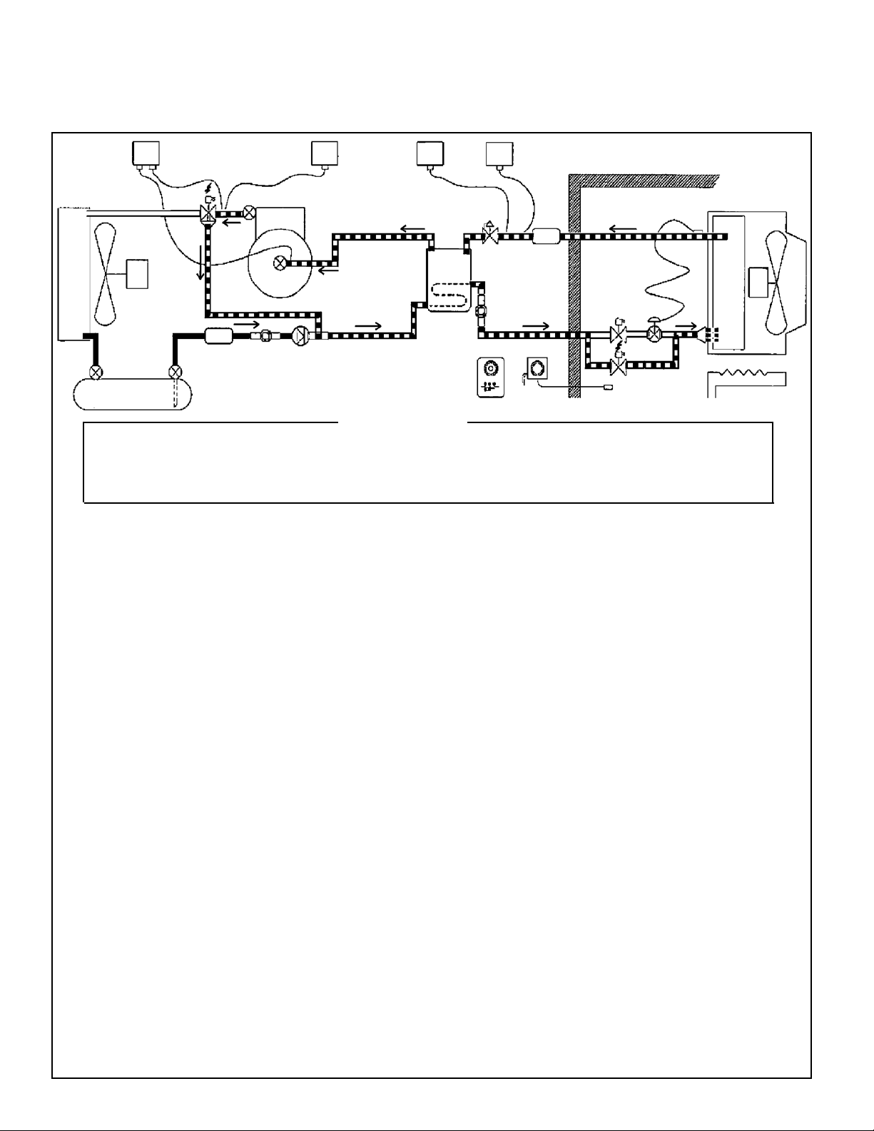
The refrigeration cycle results in frost formation on the
surface of the evaporator. This frost will eventually build
up to the point where it will restrict the air ow causing a
loss of refrigeration capacity. To prevent this, a timeclock
(I), usually set to repeat every 6 or 8 hours, initiates a
defrost cycle which melts the frost.
The clock de-energizes (closes) the liquid line solenoid
valve which causes the compressor to pumpdown and
shut off from the low pressure control. The clock also
energizes the drain pan heater (J) in the evaporator and
timer relay which after a two or more minute delay energizes (opens) the 3-way valve and hot gas solenoid valve
(K) which then builds up pressure in the evaporator causing
the low pressure control to close and start the compressor.
The hot discharge gas from the compressor ows through
the 3-way valve forcing all the liquid left in the liquid line
into the evaporator. If pressure builds up too high the
3-way valve safety pressure control (L) will de-energize
the solenoid valve and allow pressure to relieve through
the condenser.
Pressures within the evaporator will increase during the
defrost. The outlet pressure regulator (H) maintains a desired pressure differential in the system, as well as reducing the amount of liquid refrigerant back to the accumulator.
The regulator also minimizes any high suction pressure
avoiding compressor motor overloads.
Once all the frost has melted the pressure will continue to rise until the defrost termination pressure
control (M) energizes the timeclock’s internal solenoid terminating the defrost cycle. The 3-way valve,
hot gas valve solenoids are then de-energized. The
liquid line solenoid valve opens and the compressor
continues to run. The evaporator fans do not start
up until the pressure in the evaporator is low enough
to close the Fan delay control (N). By delaying the
fans this allows any moisture left on the coil to drain
away or freeze. As soon as the evaporator fans are
energized the system will then resume back to the
refrigeration cycle.
The cycle continues until the room temperature is
satised.
This de-energizes the liquid line solenoid, initiating a
pumpdown cycle that reduces the suction pressure to
the cut-out setting on the low pressure control which
de-energizes the compressor.
Page 5

WIRING DIAGRAMS
K40-THERM-PDI-13
- 5 -
02/12/10
TYPICAL SYSTEM WITH LOW PROFILE EVAPORATOR
Page 6

WIRING DIAGRAMS
K40-THERM-PDI-13
- 6 -
02/12/10
TYPICAL SYSTEM WITH MEDIUM PROFILE EVAPORATOR
Page 7

WIRING DIAGRAMS
K40-THERM-PDI-13
- 7 -
02/12/10
TYPICAL SYSTEM WITH HIGH PROFILE EVAPORATOR
Page 8

INSTALLATION
K40-THERM-PDI-13
- 8 -
02/12/10
For general installation procedures refer to the Condensing unit Installation and
Maintenance instructions included with the unit. (Bulletin K40-CU-IM, part # 1068155)
THERMOSAVER CONTROL SETTINGS
The following controls should be initially set as listed
below and then MUST be re-adjusted to suit local eld
conditions.
Dual (HI-Lo) Pressure Control
The High side setting is strictly a safety cut out (in the
event of a high pressure build up due to condenser fan
failure, blocked condenser air or restriction in the
discharge line etc.) The control is normally closed. The
low side setting should be adjusted for a pumpdown
mode. When the space thermostat is satised the
liquid line solenoid de-energizes (closes) causing the
pumpout. The low pressure control then opens up,
de-energizing the compressor contactor coil.
See Table 1 for initial settings
Three-way High Pressure Control
During the defrost cycle the three way solenoid valve
(or separate N/O and N/C hot gas solenoid valve) is
energized by the three way pressure switch which is
normally closed. This control only operates during the
defrost cycle. It is a safety control to prevent the
discharge pressure from reaching excessive pressures.
It is important this is set high enough to prevent
unnecessary short cycling. In the event of a trip it will
de-energize the Three way solenoid valve. This control
MUST be set to cut out at a lower cut-out setting than
that of the main high pressure control.
See Table 1 for initial settings.
Defrost Termination Pressure Control
After all the ice and frost has melted on the evaporator
coil, the suction pressure will rapidly rise and once a
pre-set pressure is reached (the cut-in pressure setting)
the control closes and energizes the Timeclock’s “X”
terminal which then terminates the hot gas defrost.
This control must be carefully set to suit the local eld
conditions. Too low of a cut in setting will terminate the
defrost too soon (which may still leave some ice/frost
on the evaporator). Too high of a cut-in setting may extend the defrost period and cause excessive oodback
to the compressor as well as adding unnecessary heat
to the evaporator. See Table 1 for initial settings.
An ideal setting for the control is after the evaporator
coil is completely clear of frost, there is an approx 2
minute time period before the defrost cycle terminates.
Fan Delay Pressure Control
Once the defrost cycle has terminated the refrigeration
cycle then starts back up (liquid line solenoid opens and
feeds the TXV). To prevent any moisture and water droplets
from blowing off the evaporator coil the fans must be
delayed. The fan delay pressure control is open (above the
cut-in set point) at the start of the cycle, which de-energizes
the fan contactor. Once the suction pressure starts to drop,
the evaporator becomes colder and re-freezes any water
left remaining on the coil. At this time the pressure drops
to the cut-in set point and energizes the fan contactor. The
fan delay pressure control should not be set at too low of a
cut-in setting since it will delay the fans too long. See Table
1 for initial settings.
Outlet Pressure Regulator
During refrigeration mode, this valve regulates the outlet
pressure and ensures that the suction pressure does not
rise above the set point (adjustable). This limits the pressure
to the compressor to an acceptable pressure that prevents
the compressor motor from overloading. During defrost this
regulator provides ideal pressure differential through the
evaporator during defrost. Further, the properly set regulator
can minimize the ood back. A correct setting of the regulator plays a crucial role in defrost operation. The maximum
setting should be no higher than the pressure equivalent to
the compressor maximum allowed saturated suction temperature (SST). The minimum setting should be no lower
than the pressure equivalent of 15°F above the compressor normal operating evaporating temperature. See Table
2 for initial settings.
Page 9

INITIAL PRESSURE SETTINGS (PSIG)
K40-THERM-PDI-13
- 9 -
02/12/10
SETTINGS MUST BE FINE TUNED TO SUIT FIELD CONDITIONS
Note: Various control manufacturer types result in different range scale and differential congurations. (Refer to the
control manufacturers instructions for these details) The table below covers the switch action as High or Low event and
the applicable switch position (open or closed). Most manufacturers use the Range scale as the high event value. The
differential setting value will be the difference between the high event less the low event pressure.
TABLE 1
PRESSURE CONTROL HIGH EVENT LOW EVENT HIGH EVENT LOW EVENT
Main Low Press
Main High Press (Air Cooled) 360 (open) 300 (close) 400 (open) 340 (close)
Main High Press (Water Cooled) 300 (open) 240 (close) 360 (open) 300 (close)
Three-way High Press (Air Cooled)
Three-way High Press (Water Cooled)
Defrost Termination Press 120 (close) 80 (open) 145 (close) 90 (open)
Fan Delay Press (Med Temp application) 70 (open) 40 (close) 85 (open) 50 (close)
Fan Delay Press (Low Temp application) 55 (open) 25 (close) 70 (open) 35 (close)
*
*
Set for Pumpdown mode and suited to Application and Ambient
340 (open) 280 (close) 380 (open) 320 (close)
280 (open) 220 (close) 340 (open) 280 (close)
R22 R404A
- see P.27 of Installation Manual
* Must be set at 20 PSIG lower than the main safety HP control.
Defrost Timeclock
This controls the refrigeration and defrost cycles. During
refrigeration it provides power to the space thermostat
and liquid line solenoid valve. During the defrost cycle it
de-energizes the power to the space thermostat and liquid
line solenoid valve and energizes the drain pan heater
and hot gas time delay relay (2 minutes or more). After
the delay it then energizes the hot gas solenoid valve and
three way hot gas valve. The clock has an internal solenoid relay that once energized by the defrost termination
pressure control, switches the clock contacts back to the
refrigeration cycle mode. The clock has a fail safe setting
that will terminate the defrost after a set time period.
Suggested initial settings: 4 defrosts per day / 20
minutes fail safe MAX.
Hot Gas Time Delay Relay
This timer allows the drain pan to be pre-heated prior
to the defrost cycle. This timer also allows the evaporator
to be pumped out prior to the defrost cycle. In some
applications (extra- low temp. freezers) the timer may
have to be set for a longer delay if the drain pan does
not clear properly, and must be set at a longer delay
than the compressor time delay (if equipped).
Suggested initial setting: 2 minutes.
Note:
1. Liquid line only needs to be sized based on
refrigeration mode. Long line run (over 100 ft) and
oversizing will result in excessive ood back during
defrost cycle.
2. During the start of the defrost cycle (timeclock
switches to defrost) ensure the time delay is
adjusted to (1) properly pre-warm the drain pan
heater and (2) ensure all of the refrigerant is removed
from the low side system and has performed a
pumpdown cycle. Increase the setting if necessary for
a longer delay.
TABLE 2
Note: To speed up pull down during start-up, the regulating valve may be opened temporarily.
INITIAL HOT GAS REGULATING VALVE SETTING
SETTINGS MUST BE FINE TUNED TO SUIT FIELD CONDITIONS
EVAP TEMP. (°F) R22 (PSIG) R404A (PSIG)
-40 to -30 15 20
-29 to -20 20 30
-19 to 0 40 50
1 to 10 50 65
11 to 25 60 80
Page 10

TROUBLESHOOTING GUIDE
K40-THERM-PDI-13
- 10 -
02/12/10
PROBLEM POSSIBLE CAUSES
Compressor is ooding back It is normal for refrigerant to ood back to the suction accumulator during the
latter part of the defrost cycle and after defrost. However if excessive refrigerant oods back past the accumulator then following areas need attention:
1. Is there an excessive overcharged system charge? Reduce charge.
2. Are the defrost controls set up properly? See P. 9 Table 1
3. Are liquid lines too big and long? Do not size the liquid by hot gas sizing
method. Liquid line should be sized for refrigeration liquid requirement only.
4. Defrost cycle is on too long.
Defrost cycle is longer than 15
minutes.
Evaporator coil not clear of
ice after defrost.
Ice building up at drain pan. 1. Pre-heat cycle too short (increase time delay)
1. Has drain pan had adequate pre-heat time? (Increase time delay)
2.Check that CPR is not set too high. (follow guidelines)
3. Check Defrost termination setting. (lower the setting)
1. Defrost time too short. Improper defrost (increase termination setting,
re-adjust CPR valve, follow guidelines)
2. Timeclock defrost time duration setting too short.
3. Inadequate hot gas supply. Malfunction of Three-way or HG solenoid valves.
4. Not enough defrosts per day.
5. Excessive inltration. Reduce humidity, install air curtains
2. Improper slope in drain pan.
3. Blocked drain line (unheated, not insulated)
4. Drain pan heater issue - low voltage, miswiring.
Compressor does not run
during defrost cycle.
5. Not enough defrosts per day
6. Lack of or improper P-trap in drain line.
1. It is normal for the compressor not to run during the drain pan pre-heat
period. (unless due to compressor pump-down)
2. Compressor anti-short cycle time delay is still timing out after drain pan
heater timer has timed out. Ensure compressor timer is not set for longer time
period than the Drain Pan Timer. (i.e. if compressor is set at 2 minutes ,then
pan timer should no shorter than 3 minutes. If compressor timer is set at 5
minutes then pan timer must be at least at 6 minutes, etc.) Note: Energizing
the hot gas solenoids without the compressor starting up can result in major
defrosting problems.
Page 11

SERVICE PARTS LIST
K40-THERM-PDI-13
- 11 -
02/12/10
DESCRIPTION PART NUMBER
Hot Gas Time Delay Relay 1049535
Defrost Termination Pressure Control 1049770 (1/4 SAE)
Fan Delay Pressure Control 1045264 (1/4 SAE)
Three Way Valve Pressure Control 1064271 (1/4 SAE)
PROJECT INFORMATION
System
Model Number Date of Start-Up
Serial Number Service Contractor
Refrigerant Phone
Electrical Supply Fax
Page 12

Finished Goods Warranty
02/12/10
The terms and conditions as described below in the General Warranty Policy cover all products
manufactured by National Refrigeration.
GENERAL WARRANTY POLICY
Subject to the terms and conditions hereof, the Company warrants all Products, including Service Parts,
manufactured by the Company to be free of defects in material or workmanship, under normal use and
application for a period of one (1) year from the original date of installation, or eighteen (18) months from
the date of shipment from the Company, whichever occurs rst. Any replacement part(s) so supplied will
be warranted for the balance of the product’s original warranty. The part(s) to be replaced must be made
available in exchange for the replacement part(s) and reasonable proof of the original installation date of
the product must be presented in order to establish the effective date of the warranty, failing which, the effective date will be based upon the date of manufacture plus thirty (30) days. Any labour, material, refrigerant, transportation, freight or other charges incurred in connection with the performance of this warranty
will be the responsibility of the owner at the current rates and prices then in effect. This warranty may be
transferred to a subsequent owner of the product.
THIS WARRANTY DOES NOT COVER
(a) Damages caused by accident, abuse, negligence, misuse, riot, re, ood, or Acts of God (b) damages
caused by operating the product in a corrosive atmosphere (c) damages caused by any unauthorized
alteration or repair of the system affecting the product’s reliability or performance (d) damages caused
by improper matching or application of the product or the product’s components (e) damages caused by
failing to provide routine and proper maintenance or service to the product (f) expenses incurred for the
erecting, disconnecting, or dismantling the product (g) parts used in connection with normal maintenance,
such as lters or belts (h) products no longer at the site of the original installation (i) products installed or
operated other than in accordance with the printed instructions, with the local installation or building codes
and with good trade practices (j) products lost or stolen.
No one is authorized to change this WARRANTY or to create for or on behalf of the Company any
other obligation or liability in connection with the Product(s). There is no other representation, warranty
or condition in any respect, expressed or implied, made by or binding upon the Company other than the
above or as provided by provincial or state law and which cannot be limited or excluded by such law, nor
will we be liable in any way for incidental, consequential, or special damages however caused.
The provisions of this additional written warranty are in addition to and not a modication of or subtraction
from the statutory warranties and other rights and remedies provided by Federal, Provincial or State laws.
NATIONAL REFRIGERATION &
AIR CONDITIONING CANADA CORP.
CANADA
159 ROY BLVD., BRANTFORD, ONTARIO, CANADA N3R 7K1
PHONE: 1-800-463-9517 (519)751-0444 FAX (519)753-1140
USA
985 WHEELER WAY, LANGHORNE, PA. 19047 USA
PHONE:1-888-KEEPUS1 OR 1-888-533-7871
Due to National Refrigeration’s policy of continuous product improvement, we reserve the right to make changes without notice.
 Loading...