

Page 1
NATIONAL
06/06/11
SmartVapII
TM
REFRIGERATION
PROGRAM SPECIFICATIONS
AND OPERATING
INSTRUCTIONS
1093776
Mechanical Defrost
Control System
Electrical Power:
208-230/1/60 - Electric Defrost
120V-230V/1/60 - Air Defrost
MECHANICAL
FEATURES:
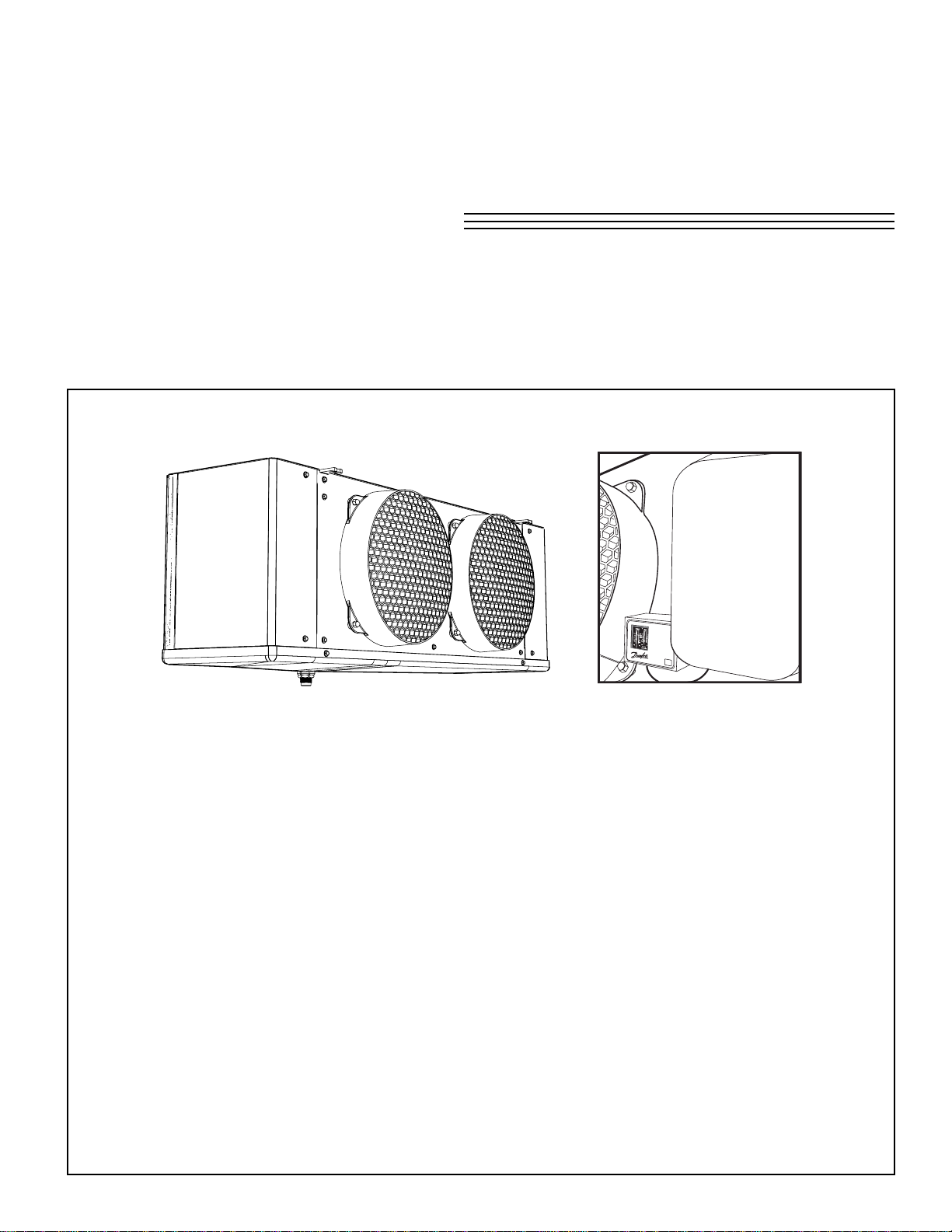
· For use with 230V Low Prole Electric Defrost Evaporators
· Also available for 120V or 230V Air Defrost Evaporators
· Simple eld hook up –Two Pipes-Two Wires –It’s Done
· No wiring required to condensing unit / No eld adjustments /set up
· Thermostat and defrost controls all factory set (-10°F freezer/ +34°F cooler)
· Simple user-friendly adjustments/ programming (if required)
CONTENTS
Operating Instructions ............................................................................................ 2
Wiring Diagrams ................................................................................................... 3 - 6
Troubleshooting Guide......................................................................................... 7
Page 2
OPERATING INSTRUCTIONS
1093776
- 2 -
06/06/11
Electric Defrost Factory Settings:
The following are the factory default settings and will suit
most applications:
· Room Thermostat Set Point :
-5°F cut-in for freezer, and +35°F for cooler
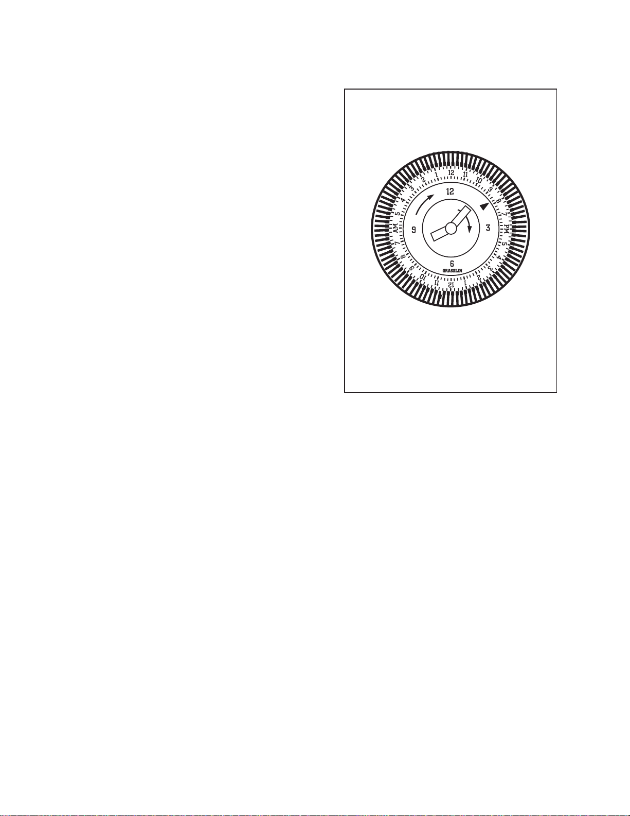
· Defrost Frequency: 4 cycles per day (24 hours)
with maximum fail safe set for 45 minutes.
(three white pins tripped out at 9AM-3PM-9PM-3AM)
· Defrost Termination Set Point:
55°F (xed, non-adjustable)
· Fan Delay Thermostat Set Point:
35°F (xed, non-adjustable)
Air Defrost Factory Settings:
· Room Thermostat Set Point : 39°F cut-in
· Defrost Frequency: 3 cycles per day (24 hours)
at 45 minutes. (three white pins tripped out at
9AM-5PM-1AM)
For further adjustment details,
refer to diagram inside the clock enclosure.
For optional adjustable fan delay and
defrost termination thermostats, contact factory.
Technical Assistance:
contact the factory at 1-800-463-9517
Page 3
WIRING DIAGRAM
1093776
- 3 -
06/06/11
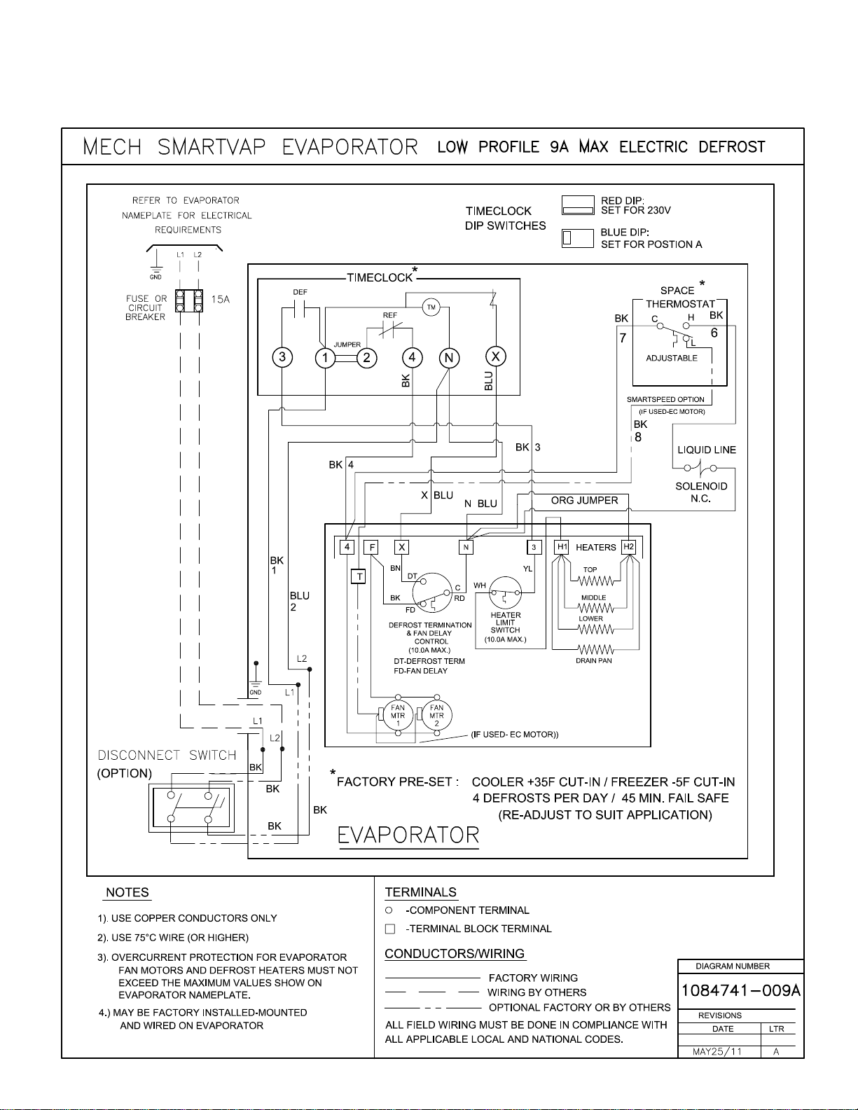
Electric Defrost Low Prole - 9A Max.
Page 4

WIRING DIAGRAM
1093776
- 4 -
06/06/11
Electric Defrost Low Prole - 12A Max.
Page 5

WIRING DIAGRAM
1093776
- 5 -
06/06/11
Electric Defrost Low Prole - 16A Max.
Page 6

WIRING DIAGRAM
1093776
- 6 -
06/06/11
Air Defrost Low Prole - 12A Max.
Page 7

TROUBLESHOOTING GUIDE
1093776
- 7 -
06/06/11
WARNING: These guidelines are intended only for qualied service personnel familiar with troubleshooting
procedures at hazardous high voltage.
For any evaporator performance troubleshooting refer to the evaporator Product Data and Installation manual supplied
with the evaporator.
For Timeclock operating information refer to the Grasslin instruction manual.
Ensure timeclock has the correct DIP switch settings. Red switch should be set to 230V mode (Electric Defrost) or as
required (120V or 230V) on the Air Defrost models. The blue DIP set to A position.
Service replacement part# for the DTMV40 timeclock is 1084740.
For further adjustment details,
refer to diagram inside the clock enclosure.
For optional adjustable fan delay and
defrost termination thermostats, contact factory.
Technical Assistance or Further Information:
contact the factory at 1-800-463-9517
Page 8

NOTES
06/06/11
NATIONAL REFRIGERATION
& AIR CONDITIONING CANADA CORP.
159 ROY BLVD., BRANTFORD, ONTARIO, CANADA N3R 7K1
PHONE: 1-800-463-9517 (519)751-0444 FAX (519)753-1140
Due to National Refrigeration’s policy of continuous product improvement, we reserve the right to make changes without notice.
 Loading...