

Page 1
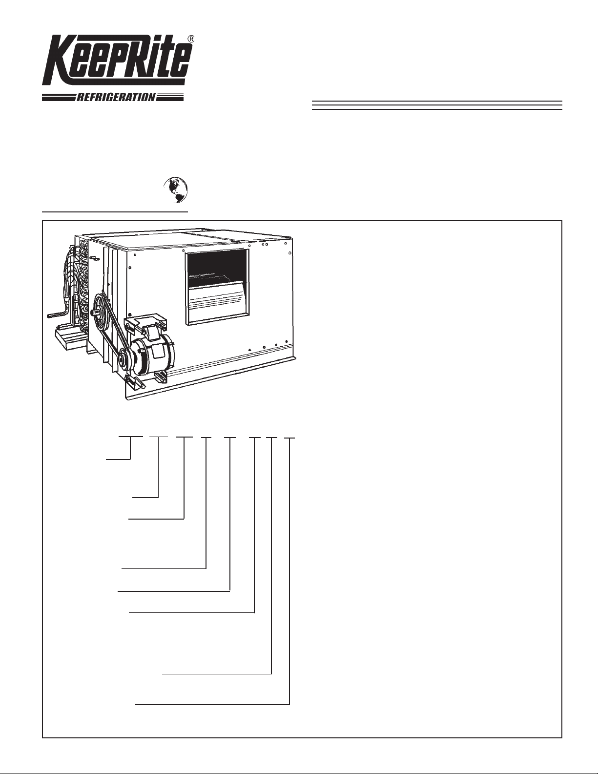
PCC Horizontal
Product Coolers
PRODUCT DATA &
INSTALLATION
Bulletin K30-PCC-PDI-10
1064048
We are on the Internet
www.keepriterefrigeration.com
Air Defrost for Applications 35 °F
(1.6 °C) (Electric and Hot Gas Defrost
Models are Optional)
Up to 30 Tons Nominal Capacity
• Large face area centrifugal fan
• New “bolt-on” coil for maximum capacity in a minimum
space.
• Electronically balanced high efficiency fans with forward
curved blades provide quiet operation.
• Heavy gauge galvanized steel cabinet.
• Self-aligning ball bearings and heavy channel stiffeners
eliminate vibration and ensure quiet operation.
NOMENCLATURE
PCC 870 ED 4 5 A - -
PRODUCT
COOLER
CENTRIFUGAL FAN
MODEL NUMBER
DEFROST TYPE
HT = HIGH TEMP AIR
ED = ELECTRIC DEFROST
HG = HOT GAS
FIN SP ACING
ROWS DEEP
FIN THICKNESS
ALUM COPPER
A = .0055 D = . 005 5
B = .0075 E = .009
C = .009
FAN MOTOR AND DRIVE
AND MFG. OPTIONS
• Full size access doors for easy maintenance.
CONTENTS PAGE
Nomenclature......................................
Capacity Data.......................................
Correction Factor................................
Blower Data.........................................
General Data........................................
Dimensional Data................................
Installation Instructions......................
Service Log.........................................
Project Information.............................
Cover
7, Back
2
2
3
4
5, 6
Back
Back
FAN INSULA TION
- = NO INSULA TION
I = INSULA TION
Page 2

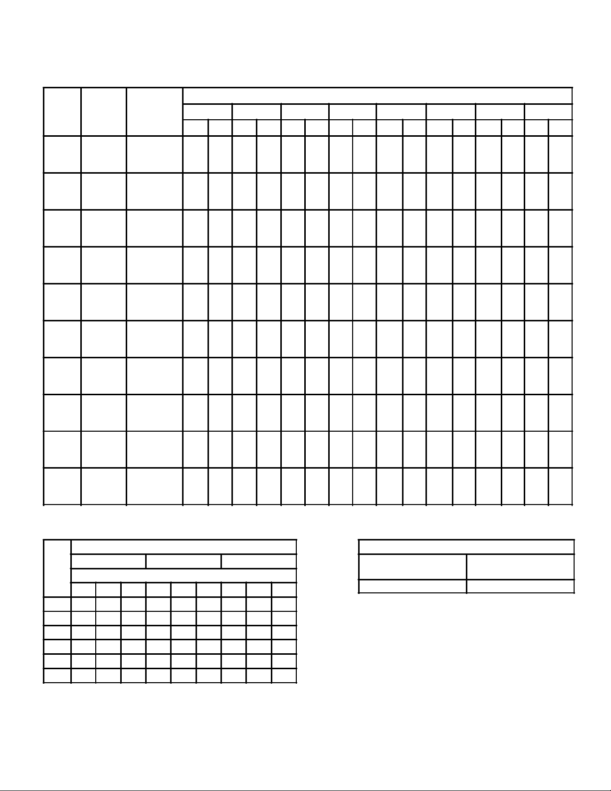
CAPACITY DATA
COOLING CAPACITIES - BTU / H °F T.D.
BASED ON 600 FPM (183m/min) FACE VELOCITY)
COIL ENT. AIR FROM 32°F (0°C) to 35°F
(1.6°C)
FIN SPACING FIN SPACING
8/INCH 6/INCH 4/INCH 6/INCH 4/INCH
DX DX DX DX DX
3460
4420
5040
5610
4630
5920
6750
7500
5810
7410
8450
9400
6980
8940
10160
11300
8560
10920
12490
13870
10480
13630
15560
17260
14270
18280
20780
23060
16250
20760
23660
26270
19000
24320
27740
30780
23700
30450
34680
38480
3210
4120
4670
5200
4310
5520
6290
6980
5400
6940
7880
8740
6510
8310
9450
10500
7960
10180
11560
12890
9950
12730
14440
16120
13240
17000
19290
21470
15110
19360
21900
24420
17650
22610
25750
28600
22040
28260
32210
35720
2630
3360
3830
4270
3520
4510
5130
5730
4410
5650
6450
7170
5310
6800
7750
8620
6530
8330
9500
10580
8120
10400
11820
13180
10850
13920
15750
17580
12310
15770
17950
20050
14460
18430
21090
23420
18050
23040
26320
29360
FACE VELOCITY CAPACITY CORRECTION FACTORS
TABLE 1
Face Velocity
F.P.M.
(m/min.)
600 (183)
500 (152)
400 (122)
MODEL
No.
PCC
870
PCC
1170
PCC
1470
PCC
1770
PCC
2270
PCC
2870
PCC
3770
PCC
4170
PCC
5070
PCC
6470
CFM *
(Litre/sec.) @
600 FPM
(183m/min.)
6,340
(2,992)
8,500
(4,012)
10,650
(5,026)
12,800
(6,041)
15,700
(7,410)
19,600
(9,250)
26,150
(12,341)
29,800
(14,064)
34,900
(16,471)
43,600
(20,577)
FACE
AREA
SQ. FT.
(m2)
10.5
(.975)
14.1
(1.30)
17.7
(1.64)
21.3
(1.97)
26.2
(2.43)
32.6
(3.02)
43.6
(4.05)
49.6
(4.60)
58.1
(5.39)
72.6
(6.74)
ROWS
DEEP
4
6
8
10
4
6
8
10
4
6
8
10
4
6
8
10
4
6
8
10
4
6
8
10
4
6
8
10
4
6
8
10
4
6
8
10
4
6
8
10
* For Applications in room temperatures above 35 °F (1.6 °C) maximum face velocity should not exceed 500 FPM
(152m/min) and capacities corrected accordingly (see table 1 for correction factors).
** These ratings are based on moderate coil frosting. For heavy frosting use factor of 0.95.
(1) “T.D.” - Represents the difference between temperature
of air entering cooling coil and coil refrigerant temperature.
Ratings for units using electric defrost may be determined by
multiplying ratings in above table by 0.95
(1)
**COIL ENT. AIR BELOW 32°F
(0°C)
2870
3800
4480
5020
3840
5120
6010
6740
4820
6400
7530
8440
5790
7690
9070
10150
7120
9420
11100
12450
8860
11820
13870
15450
11880
15750
18480
20660
13460
17830
21040
23480
15790
20980
24610
27600
19780
26170
30880
34580
Rows Deep In Direction Of Airflow
4 6 8 10
1.0
.91
.80
1.0
.90
.78
1.0
.89
.76
2350
3130
3680
4120
3150
4200
4930
5510
3940
5250
6170
6920
4750
6330
7410
8290
5830
7750
9080
10180
7270
9660
11360
12720
9710
12890
15170
16880
10990
14630
17150
19240
12920
17220
20200
22610
16090
21520
25220
28240
1.0
.89
.73
- 2 -
Page 3
BLOWER DATA
FAN RPM AND MOTOR HP REQUIREMENTS
PCC
MODEL
870
1170
1470
1770
2270
2870
3770
4170
5070
6470
FACE
VELOCITY
FPM
(m/min.)
400 (122)
500 (152)
600 (183)
400 (122)
500 (152)
600 (183)
400 (122)
500 (152)
600 (183)
400 (122)
500 (152)
600 (183)
400 (122)
500 (152)
600 (183)
400 (122)
500 (152)
600 (183)
400 (122)
500 (152)
600 (183)
400 (122)
500 (152)
600 (183)
400 (122)
500 (152)
600 (183)
400 (122)
500 (152)
600 (183)
CFM
(litre/sec.)
4,220 (1,992)
5,290 (2,497)
6,340 (2,992)
5,670 (2,676)
7,090 (3,346)
8,500 (4,012)
7,100 (3,351)
8,800 (4,153)
10,650 (5,026)
8,540 (4,030)
10,680 (5,040)
12,800 (6,041)
10,480 (4,946)
13,100 (6,183)
15,700 (7,410)
13,060 (6,164)
16,330 (7,707)
19,600 (9,250)
17,440 (8,231)
21,800 (10,289)
26,150 (12,341)
19,860 (9,373)
24,820 (11,714)
29,800 (14,064)
23,250 (10,973)
29,060 (13,715)
34,900 (16,471)
29,060 (13,715)
36,330 (17,146)
43,600 (20,577)
TOTAL STATIC PRESSURE (INCHES - WATER GAUGE)
TSP=.125" TSP=.25" TSP=.50" TSP=.75" TSP=1.00" TSP=1.25" TSP=1.50" TSP=1.75"
RPM BHP RPM BHP RPM BHP RPM BHP RPM BHP RPM BHP RPM BHP RPM BHP
440
0.56
475
0.66
542
0.84
608
1.04
676
1.28
744
1.52
810
1.77
870
2.03
530
1.09
560
1.19
613
1.39
667
1.63
722
1.90
778
2.16
833
2.44
887
2.73
630
1.72
650
1.94
697
2.18
740
2.44
785
2.72
830
3.01
878
3.32
925
3.65
438
0.98
465
1.08
522
1.29
580
1.55
635
1.87
692
2.20
751
2.53
807
2.88
533
1.87
560
1.98
600
2.20
640
2.47
682
2.78
738
3.14
780
3.54
828
3.94
621
3.18
640
3.31
679
3.57
716
3.85
754
4.17
792
4.52
830
4.92
872
5.35
515
1.11
555
1.26
637
1.57
716
1.89
801
2.24
865
2.61
934
3.00
1000
3.42
612
2.00
648
2.20
718
2.59
784
2.97
848
3.36
912
3.76
973
4.19
1033
4.65
730
3.43
758
3.68
815
4.17
867
4.63
928
5.09
980
5.55
1035
6.02
1086
6.51
470
1.29
490
1.46
565
1.81
637
2.21
707
2.64
775
3.09
839
3.57
900
4.01
562
2.38
580
2.60
640
3.04
700
3.49
757
3.96
813
4.47
869
5.01
924
5.57
653
3.96
669
4.23
723
4.77
773
5.30
822
5.84
870
6.39
918
6.97
966
7.58
423
1.60
447
1.82
513
2.25
579
2.74
642
3.26
704
3.82
762
4.40
817
5.01
508
2.98
530
3.24
584
3.77
637
4.33
688
4.91
741
5.54
791
6.20
840
6.89
591
5.03
614
5.34
663
5.97
709
6.62
751
7.27
796
7.97
840
8.67
881
9.44
308
1.65
339
1.95
400
2.56
457
3.23
513
3.96
565
4.72
614
5.49
661
6.28
365
3.02
395
3.40
447
4.17
495
4.94
542
5.75
587
6.62
632
7.52
686
8.46
442
4.98
454
5.45
500
6.39
542
7.30
581
8.22
620
9.17
661
10.17
697
11.21
302
2.47
322
2.87
373
3.66
422
4.52
468
5.41
513
6.35
556
7.32
596
8.31
370
4.58
392
5.05
420
5.99
456
7.00
496
8.05
535
9.14
573
10.27
610
11.42
411
7.69
432
8.24
471
9.35
507
10.49
541
11.69
574
12.92
607
14.21
639
15.53
204
2.84
220
3.33
259
4.31
293
5.26
324
6.21
353
7.22
382
8.27
408
9.36
238
5.15
255
5.79
290
7.08
321
8.29
351
9.48
375
10.65
400
11.86
423
13.09
278
8.59
293
9.38
323
10.97
352
12.49
378
14.28
401
15.39
424
16.81
446
18.20
173
3.00
190
3.54
227
4.67
260
5.72
290
6.88
317
8.10
342
9.36
367
10.67
205
5.49
221
6.15
251
7.48
280
8.83
308
10.20
333
11.61
356
13.06
380
14.55
243
8.15
254
9.94
280
11.53
300
13.14
330
14.76
352
16.40
374
18.05
396
19.74
165
3.96
178
4.68
210
6.13
238
7.54
264
8.96
288
10.42
312
11.94
335
13.53
191
7.20
205
8.10
234
9.90
260
11.71
283
13.48
305
15.24
325
17.01
345
18.80
223
11.90
235
13.08
260
15.19
284
17.38
306
19.61
326
21.70
344
23.81
362
25.92
INTERNAL AIRSIDE RESISTANCE - INCHES, W. G. WET COIL CORRECTION FACTOR*
Coil
Rows
Deep
400 (122) 500 (152) 600** (183)
Fins Per Inch
4 6 8 4 6 8 4 6 8
4 .09 .12 .14 .13 .17 .20 .18 .23 .27
5 .12 .14 .16 .17 .21 .25 .23 .28 .34
6 .13 .16 .20 .20 .25 .30 .27 .34 .41
8 .18 .23 .27 .27 .34 .41 .35 .44 .53
10 .23 .28 .34 .34 .42 .51 .45 .56 .68
12 .27 .34 .41 .39 .49 .59 .53 .67 .81
** Coil face velocity should not exceed 500 FPM (152 m/min.)
for applications where room temperature is above 35 °F
(1.6 °C).
COIL FACE VELOCITY FPM (m/min)
* For medium frosted coil, use factor of 1.3
Example:
600 FPM (183 m/min.), 8 row coil 4 fins/in.
Evap. Temp. 40 °F (4.4 °C)
Ent. Air Dew Pont 45 °F (7.2 °C)
Internal Airside Resistance - .35
Wet Coil Correction factor = 1.12
Total Internal Airside
Resistance = 1.12 x .35 = .392
Ent. Air Dew Point Minus Refr. Temp.
10ºF (5.5ºC)
or Less
11ºF (6.1ºc) to
18ºF (10ºC)
1.12 1.24
- 3 -
Page 4

LARGE FACE AREA
COIL CIRCUITED FOR
EFFICIENT PERFORMANCE
GENERAL DATA
HEAVY CONTINUOUS
GALVANIZED STEEL CASINGS
BOLT ON COIL
ENSURES UNITIZED
CONSTRUCTION
GALVANIZED
FULL WIDTH DRAIN PAN
WITH ADEQUATE SLOPE
PHYSICAL DATA
MODEL NUMBER
FAN DATA
- No.
ins. 15 16 1/2 13 1/2 15 16 1/2 20 22 1/4 33 36 1/2 40 1/4
- Dia.
mm 381 419.1 342.9 381 419.1 508 565.1 838.2 927.1 1022.3
sq. ft. 2.82 3.45 4.65 5.63 6.90 10.26 12.42 13.79 16.77 20.48
Outlet Area
m
COIL DATA:
ins.
Face Size
mm
sq. ft. 10.5 14.1 17.7 21.3 26.2 32.6 43.6 49.6 58.1 72.6
Face Area
m
ELECTRIC DEFROST *
KW. REQUIREMENTS
4 6.1 7.1 8.6 12.1 13.8 17.3 17.3 19.6 21.9 26.3
LARGE
MAN SIZE
ACCESS DOORS
STURDY HEAVY GAUGE
STEEL CHANNEL SUPPORTS
PCC 870 PCC 1170 PCC 1470 PCC 1770 PCC 2270 PCC 2870 PCC 3770 PCC 4170 PCC 5070 PCC 6470
1 1 2 2 2 2 2 1 1 1
2
.261 .320 .431 .523 .731 .953 1.15 1.28 1.55 1.90
34 1/2 x4434 1/2 x5934 1/2 x7434 1/2 x8940 1/2 x9340 1/2 x
116 1/4
876 x
1118
2
.975 1.30 1.64 1.97 2.43 3.02 4.05 4.60 5.39 6.74
876 x
1499
876 x
1880
876 x
2261
1029 x
2362
1029 x
2953
52 1/2 x
116 1/4
1334 x
2953
61 1/2 x
116 1/4
1562 x
2953
72 x
116 1/4
1829 x
2953
90 x
116 1/4
2286 x
2953
Rows Deep
HOT GAS DEFROST
DRAIN PAN CONNS.
6 6.1 7.1 8.6 12.1 13.8 17.3 17.3 19.6 21.9 26.3
8 7.1 9.1 11.1 13.6 15.6 21.8 21.8 24.1 28.6 35.3
10 9.1 11.1 13.6 16.6 19.1 26.3 26.3 30.8 35.3 44.3
ALL SIZES 1-5/8" (41 mm) O.D. COPPER
* Defrost heaters rated for 230 volt or 575 volt operation.
SHIPPING WEIGHTS
MODEL NUMBER PCC 870 PCC 1170 PCC 1470 PCC 1770 PCC 2270 PCC 2870 PCC 3770 PCC 4170 PCC 5070 PCC 6470
*Fan Section
Drive and Motor
550 lbs.
249.4 kg
600 lbs.
272.1 kg
750 lbs.
340.1 kg
850 lbs.
385.5 kg
1,000 lbs.
453.5 kg
1,270 lbs.
576 kg
1,640 lbs.
743.8 kg
1,950 lbs.
884.5 kg
2,700 lbs.
1224.6 kg
3,610 lbs.
1637.4 kg
* This weights are for fan section, drive and motor only. Coil weights must be added to the weights shown above.
COIL
WEIGHTS
The weight of the copper / aluminium coils may be calculated on the basis of 6 lbs. (2.7 kg)
per square ft. face area / row deep.
Note: Metric figures are approximate to eliminate excessive decimals.
- 4 -
Page 5

DIMENSIONAL DATA
MODELS PCC 870 THRU PCC 2870
MODELS PCC 3770 THRU PCC 6470
Note: Metric figures are approximate to eliminate excessive decimals.
- 5 -
Page 6

DIMENSIONAL DATA
Model
No.
PCC
870
PCC
1170
PCC
1470
PCC
1770
PCC
2270
PCC
2870
PCC
3770
PCC
4170
PCC
5070
PCC
6470
A B D E F G H K L M N P R S T U V Y
ins 48 37 3/4 36 3/4 1 1/2 42 1/2 21 1/8 19 3/4 13 7/16 56 1/4 31 1/8 20 3/8 42 1/2 37 3/4 - 18 33 1/8 44 1/8 38 1/2
mm 1219.2 958.9 933.4 38.1 1079.5 536.5 492.1 341.3 1428.7 790.5 517.5 1079.5 958.8 - 457.2 841.3 1120.7 977.9
ins 63 37 3/4 36 3/4 1 1/2 57 1/2 23 1/4 21 1/2 19 7/8 56 1/4 31 1/8 20 3/8 57 1/2 37 3/4 - 18 33 1/8 59 1/8 53 1/2
mm 1600.2 958.9 933.4 38.1 1460.5 590.5 546.1 504.8 1428.7 790.5 517.5 1460.5 958.8 - 457.2 841.3 1501.7 1358.9
ins 78 37 3/4 36 3/4 1 1/2 72 1/2 19 17 7/8 10 56 1/4 31 1/8 20 3/8 72 1/2 37 3/4 20 21 33 1/8 74 1/8 68 1/2
mm 1981.2 958.9 933.4 38.1 1841.5 482.6 454 254 1428.7 790.5 517.5 1841.5 958.8 508 533.4 841.3 1882.7 1739.9
ins 93 37 3/4 36 3/4 1 1/2 87 1/2 21 1/8 19 3/8 12 11/16 56 1/4 31 1/8 20 3/8 87 1/2 37 3/4 25 3/4 21 33 1/8 89 1/8 83 1/2
mm 2362.2 958.9 933.4 38.1 2222.5 536.5 492.1 322.1 1428.7 790.5 517.5 2222.5 958.8 644.5 533.4 841.3 2263.7 2120.9
ins 97 44 3/4 43 3/4 2 1/2 91 1/2 23 1/4 21 5/8 12 5/8 63 1/4 - - - 44 3/4 25 1/4 21 39 1/8 93 1/8 -
mm 2463.8 1136.7 1111.2 63.5 2324.1 590.5 549.2 320.6 1606.5 - - - 1136.6 641.3 533.4 993.7 2365.3 -
ins 120 44 3/4 43 3/4 2 1/2 114 1/2 28 3/16 26 1/2 15 29/32 63 1/4 - - - 44 3/4 3113/16 23 39 1/8 116 1/4 -
mm 3048.0 1136.7 1111.2 63.5 2908.3 715.9 673.1 404.0 1606.5 - - - 1136.6 808.0 584.2 993.7 2952.7 -
ins 122 1/8 57 1/2 45 5/8 2 1/2 117 7/8 31 7/16 28 3/4 15 5/32 65 1/8 - - - 39 1/2 29 1/16 25 51 7/8 116 1/4 -
mm 3101.9 1460.5 1158.8 63.5 2994 798.5 730.2 384.9 1654.1 - - - 1003.2 738.1 635 1317.6 2952.7 -
ins 122 1/8 65 3/4 59 1/8 2 1/2 117 7/8 46 3/8 43 1/4 37 7/8 78 5/8 - - - 53 - 25 60 1/8 116 1/4 -
mm 3101.9 1670 1501.7 63.5 2994 1177.9 1098.5 902 1997.1 - - - 1346.2 - 635 1527.1 2952.7 -
ins 122 1/8 75 1/2 66 5/8 1 3/4 117 7/8 51 1/2 47 1/4 35 5/16 86 1/8 - - - 60 1/2 - 25 70 5/8 116 1/4 -
mm 3101.9 1917.7 1692.2 44.4 2994 1308.1 1200.1 896.9 2187.5 - - - 1536.7 - 635 1793.8 2952.7 -
ins 122 1/8 93 1/2 72 5/8 1 3/4 117 7/8 56 3/4 52 3/8 32 11/16 92 1/8 - - - 66 1/2 - 25 88 5/8 116 1/4 -
mm 3101.9 2374.9 1844.6 44.4 2994 1441.4 1330.3 830.1 2339.9 - - - 1689.1 - 635 2251.1 2952.7 -
DIMENSIONAL DATA
MODELS PCC 870 THRU PCC 2870
MODELS PCC 3770 THRU PCC 6470
DIMENSIONAL DATA
STANDARD ON ALL MODELS
- 6 -
Page 7

INSTALLATION INSTRUCTIONS
GENERAL
The Product cooler should be carefully inspected for
damage when received. Visible or concealed damage
should be reported immediately to the carrier and a
claim filed for damage.
Product coolers are constructed from heavy gauge
galvanized steel and are thoroughly inspected before
leaving the plant. Care should be taken during
installation to prevent damage to the units.
Care should be taken to ensure that sufficient access is
available for servicing of the unit. Space should be
available for lubrication, belt adjustment and coil removal.
Fans and fan shafts should be inspected before start-up.
Fans are inspected before leaving the pant; however,
rough handling may cause misalignement.
LOCATING AND INSTALLATION HINTS
IMPORTANT: Product Coolers PCC3770, PCC4170,
PCC5070 and PCC6470 MUST be platform or floor
mounted.
Product Coolers may be placed in any suitable manner
in the room. However, low temperature units should not
be located over entrance doors, because of the heavy
frosting that will occur on the coils.
All Product Coolers must be installed level to ensure
proper drainage of water from the pre-engineered drain
pan.
Drain lines for all Product Cooler Models should be
pitched 45° and should be as short as possible. To
prevent drain line freezing problems the following recommendations should be carried out:
(a) Use a drain line heater (supplied by others) with a
density of 20 watts per foot. Six to eight feet of cable
per foot of drain line is recommended.
(b) Drain line heater should make at least a full turn
round the outlet of the drain pan.
distributor on the evaporator coil is equipped with a side
port connection to facilitate a hot gas connection.
Distributor tubes are oversized for hot gas operation.
A liquid line solenoid valve (supplied by others) should be
used so that evaporator coil may be pumped out before
each defrost cycle.
The following defrost control (supplied by others) methods
may be used with Product Coolers.
(1) TIME INITIATED- TEMPERATURE TERMINATED
When using a time initiated - temperatureterminated
method of defrosting a Paragon Timer 8145-20 or equal is
recommended for this application. Timer is used in
conjuction with a defrost termination thermostat. For 3
phase applications, the timer must be used with a contactor. As well as the defrost termination thermostat, the
timer will also have a fail safe feature built into unit.
The drfrost termination thermostat should be set at
approx. 35 °F (1.6 °C) and should be adjustable.
Differential should be 5 °F (2.8 °C) or less. Bulb should be
attached to a tube of the evaporator. As a part of this
system, a fan delay thermostat should be used to provide
a delay period between the end of the defrost and the
start-up of the fan. The fan delay thermostat should be
adjustable and set at 10-25 °F (5.6-13.9 °C) (depending on
application) and bulb should be attached to evaporator
tube. When installing thermostats, care should be taken
to ensure that bulbs are not attached to evaporator heater
tubes.
(2) TIME CONTROLLED OPERATION
Defrosting may also be carried out by a time contolled
sequense. This system utilizes a timer and fan delay
thermostat. Timer should have an adjustable length of
defrost from 2-110 minutes and should be Paragon 804520 or equal. Fan delay thermostat should be as indicated
in (1) above.
(c) The heated drain line should be insulated.
(d) The drain line should be provided with a trap outside
the freezer room. Traps should be filled with water
before initial start-up.
DEFROSTING
Product Coolers are obtainable with electric or hot gas
defrost systems. On hot gas defrost units, the
Initially, 4-30 minute defrost per day are reccomended.
However, it is important that the coil be completely
cleared of defrost at the end of the cycle. Should coil not
be cleared of all frost at the end of 30 minutes, more
frequent defrost of shorter duration should be used.
WIRING
For suggested wiring of defrost heaters see Drg. No.
41594D furnished with Product Cooler.
- 7 -
Page 8

INSTALLATION INSTRUCTIONS
03/15/2007
ST ART - UP
(a) Before start-up equipment, the amperage of all electric
defrost heaters, including drain pan heaters, motor,
etc. should be checked to ensure satisfactory
operation.
(b) Leak test entire system and make sure all joints are
tight.
(c) Check fan and motor for correct rotation.
(d) Check alignment of fan and motor sheave and belt
tension. Belts should have approx. 1” deflection.
PERIODIC SERVICE AND MAINTENANCE
1. Check all moving parts every six months for wear .
2. Check bearing collar set screws for tightness every six
months.
3. Fan bearings are pre-lubricated and do not require
lubrication at time of installation. Extended lube lines
SERVICE LOG
will have grease fittings located on unit panel.
Specific greasing instructions should be carried out in
accordance with tags and l;abels attached to unit.
Careshould be taken not to over lubricate. Grease
should be applied when unit is running, adding slowly
until there is a slight bleeding of the grease at the
seals.
For continuous operation in clean areas, in an
operating temperature range from -40 °F (-4 °C) to
140 °F (60 °C), normal lubrication interval is six
months.
ARMV AC 781, available from both Standard Oil Company and Imperial Oil Company is the recommended
lubricant for all product cooler shaft bearings.
REPLACEMENT P ARTS
When replacement parts are required on units
manufactured by KeepRite Refrigeration, furnish factory
with unit model number and serial number as shown on
serial plate on drive end blower section.
ETADSTNEMMOC
PROJECT INFORMATION
metsyS
rebmuNledoM pU-tratSfoetaD
rebmuNlaireS rotcartnoCecivreS
tnaregirfeRenohP
ylppuSlacirtcelExaF
NA TIONAL REFRIGERA TION &
AIR CONDITIONING CANADA CORP.
CANADA
159 ROY BL VD., BRANTFORD, ONT ARIO, CANADA N3R 7K1
PHONE: 1-800-463-9517 (519)751-0444 FAX (519)753-1140
Due to National Refrigeration’s policy of continuous product improvement, we reserve the right to make changes without notice.
USA
985 WHEELER WA Y, LANGHORNE, PA. 19047 USA
PHONE:1-888-KEEPUS1 OR 1-888-533-7871
 Loading...