

Page 1
PRODUCT DATA &
INSTALLATION
Bulletin K70-KWS-PDI-11
1064614
Water Cooling
Coils
Type KWS Single Serpentine
Type KWH Half serpentine
We are on the Internet
www.keepriterefrigeration.com
Water Cooling Coils ........................................2
General Specifications ....................................3
Type KWS Coil................................................4
Nomenclature..................................................4
Type KWH and KWD Water Coils...................5
General Formulas ...........................................6
Wet Bulb Depression Ratio.............................6
System Design ................................................7
Coil Selection - Sizes - Table 1 .......................7
Coil Selection - Fin Series Capacity
Correction Factors - Table 2....................8
Coil Selection - General Considerations .........8
Conversion of Air Volume to St andard Air .......9
Total Heat - Table 3........................................10
Explanation for Using Direct
Selection Tables..............................11, 12
Direct Selection - Table 4 .....................13 to 21
Example Coil Selection No. 1 ........................22
Example Coil Selection No. 2 ...................23,24
Mean Effective Temperature
Difference -Table 5 ................................25
Type KWD Double Serpentine
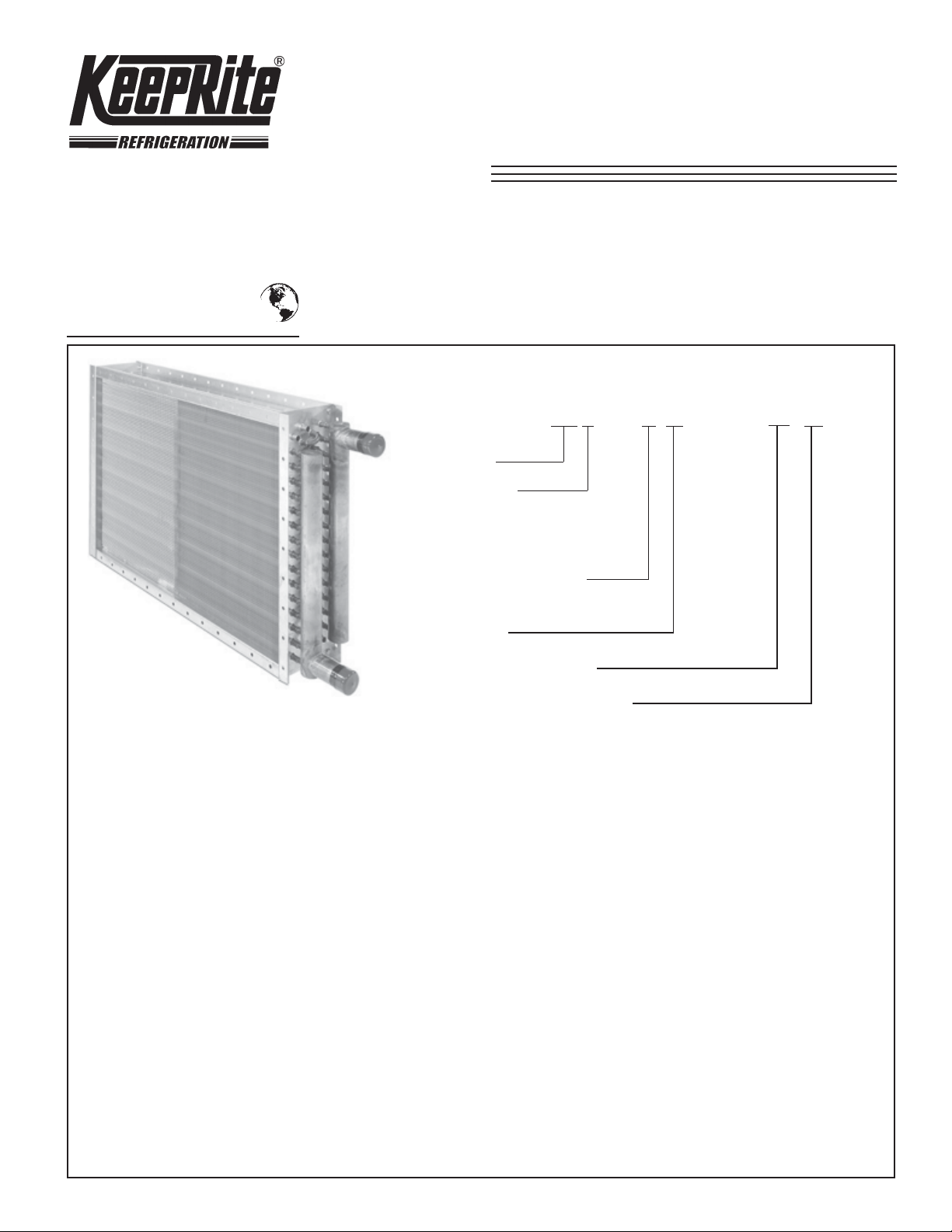
NOMENCLATURE
TYPE MODEL FACE DIMENSIONS
KW
Coil Type
CIRCUITING:
S = Single Serpentine
D = Double Serpentine
H = Half Serpentine
Fin Series (70, 80, 100
or 120) (100 shown)
Rows Deep
“W” Dimensions (inches)
Nominal Tube Length (inches)
CONTENTS
Standard Coil Circuiting - Table 6 ..................26
Wetted Surface Factor - Figure 3..................26
Heat Transfer Coef ficient - Figure 4 .............. 27
Fin Correction - Table 7 .................................27
Wet Bulb Depression Factors.......................28
Air Pressure Drop - Figure 6 ......................... 29
Air Friction Fin Series Correction
Factors -Table 8 ....................................29
Air Friction Sample Calculation
Example No.3........................................ 29
Water Pressure Drop Curve - Figure 7 .........30
Water Pressure Drop Correction Factors
and Example Problems......................... 31
Water Pressure Drop Coil Type - Table 9...... 31
Dimensional Drawings ..................................32
Application Recommendations ..................... 33
Pipe Size Selection Chart - Figure 1 1 ..........33
Psychrometric Functions ..............................34
Psychrometric Chart - Figure 16...................35
Engineering Specifications............................36
S
D
H
- 1 0 5 - 18 x 45
Page 2
Water Cooling Coils
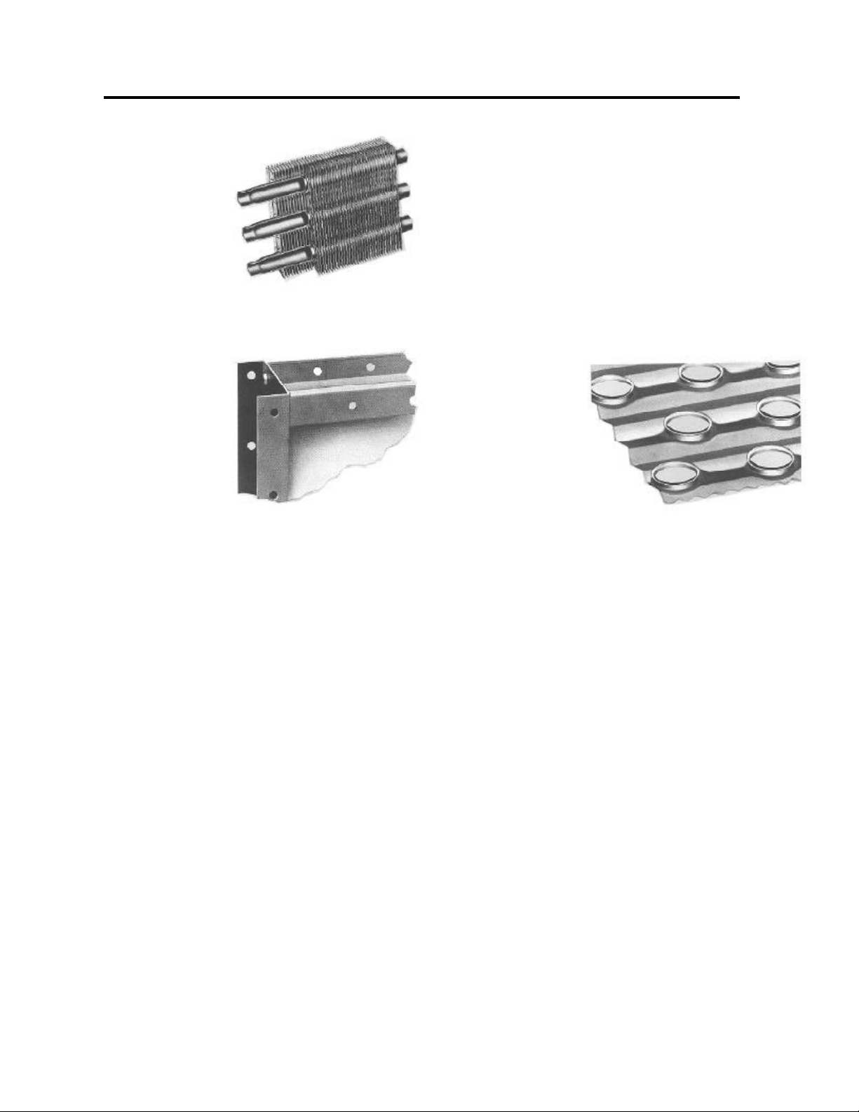
MECHANICAL
PRESSURE BOND
KeepRite Mechanical
Pressure Bond guarantees
that each tube and fin collar
make positive permanent
metal to metal contact.
No need for using low
conductivity metals or alloys,
FLANGED CASINGS
Double flanged galvanized
steel casings on all
KeepRite Water Heating
Coils provide greater
strength - better support
for easier coil stacking.
Simplifies moving and handling operations.
Top and bottom casing flanges are turned back to
form two channel sections in a “box shape”.
Provides maximum strength and durability.
COPPER TUBE HEADERS
Made from heavy gauge seamless drawn copper
tube, KeepRite designed headers lengthen coil life
- provide necessary header flexibility to
compansate for expansion and contraction during
operation.
Header flexibility also reduces coil core “strains”
during start up. Further proof that KeepRite
design means long life and top performance.
FULL FIN
COLLARS
Efficient KeepRite
fin presses perform
multi - stage operations
to draw full fin collars
with wide, smooth surfaces
that completely cover coil
tubes - actually form a tube within a tube for
greater strength and maximum heat transfer.
Lack of sharp collar edges make KeepRite
Coils easier to clean - smoother KeepRite
Collars retard lint and dirt accumulation.
- 2 -
Page 3

AVAILABLE IN FOUR STANDARD
FIN SPACING
GENERAL
SPECIFICATIONS
70 FIN SERIES is designed and used for applications re-
quiring high latent loads and for installations requiring low
air pressure drop. With the 70 Fin Series Coil, it is possible to more accurately match sensible and total loads,
particularly when the water temperature is low and the
entering wet bulb air temperature is high.
80 FIN SERIES has been more or less a standard in the
industry for 15 to 20 years. This fin series and the 100 Fin
Series surface are widely used for regular
commercial applications because the S/T ratios achieved
with these surfaces meet the normal S/T ratio
requirements.
When only the 80 Fin Series Coil surface was available,
frequently more rows of coil were required to meet either a
total or sensible load than is now required with 100 and
120 Fin Series Coils. When extra rows are furnished to
meet either a sensible or total requirement, the
excessive capacity furnished can result in something less
than ideal conditions in the conditioned space.
100 FIN SERIES introduced approximately ten years ago
by KeepRite has been furnished for special industrial
applications that require higher than normal sensible
cooling loads. Experience has shown this is an excellent
heat transfer surface, not only for high sensible load
requirements, but also for average S/T ratio jobs, when
space will not permit larger face areas and/or more rows
to be installed and capacity requirements exceed the
capabilities of 80 Fin Series Coils.
The increase in air friction that results by changing from
an 80 Fin Series to a 100 Fin Series with shallow depth
coils is usually less than the increase in air friction if one
additional row of 80 Fin Series Coil is utilized.
PRIMARY SURFACE - 5/8" O.D. round copper
tubes on 11/2" equilateral centers.
SECONDARY SURFACE-Rippled aluminum or copper, die
formed plate type fins. Fin collars are full drawn to provide
accurate control of fin spacing and to completely cover the
tube for maximum heat transfer.
HEADERS-Extra heavy seamless copper tubing. Tube
holes provide flexibility for uneven stresses and the
maximum brazing surface possible.
CONNECTIONS-Male pipe supply and return
connections.
BRAZING-All core joints are brazed with copper
brazing alloys.
CASING-Die formed heavy gauge continuous galvanized
steel with reinforced mounting flanges. Fin angles
completely brace the core assembly in the casing of all
large coils to prevent air by-pass and damage in shipment.
VENTS AND DRAINS-Furnished on all coils.
TESTS - Complete coil tested leak free at 300 PSIG
air pressure under water.
120 FIN SERIES was designed as a maximum capacity
surface with reasonable air pressure drop and is
particularly suitable for use in commercial and industrial
installations requiring higher than average sensible total
ratios.
The 120 Fin Series heat transfer surface offers the
maximum BTU capacity per dollar invested for
applications where this surface is suitable. The 120 Fin
Series provides the maximum amount of total external
surface per sq. ft. of face area per row deep that is
practical without encountering excessive air pressure
drops.
OPERATING CONDITIONS-Standard coils are suitable for
use up to 200 PSIG.
- 3 -
Page 4
WATER COOLING COILS
TYPE “KWS” COILS
Type “KWS” Coils are specifically designed and
engineered to meet most applications requiring normal
water quantities and normal water pressure drop.
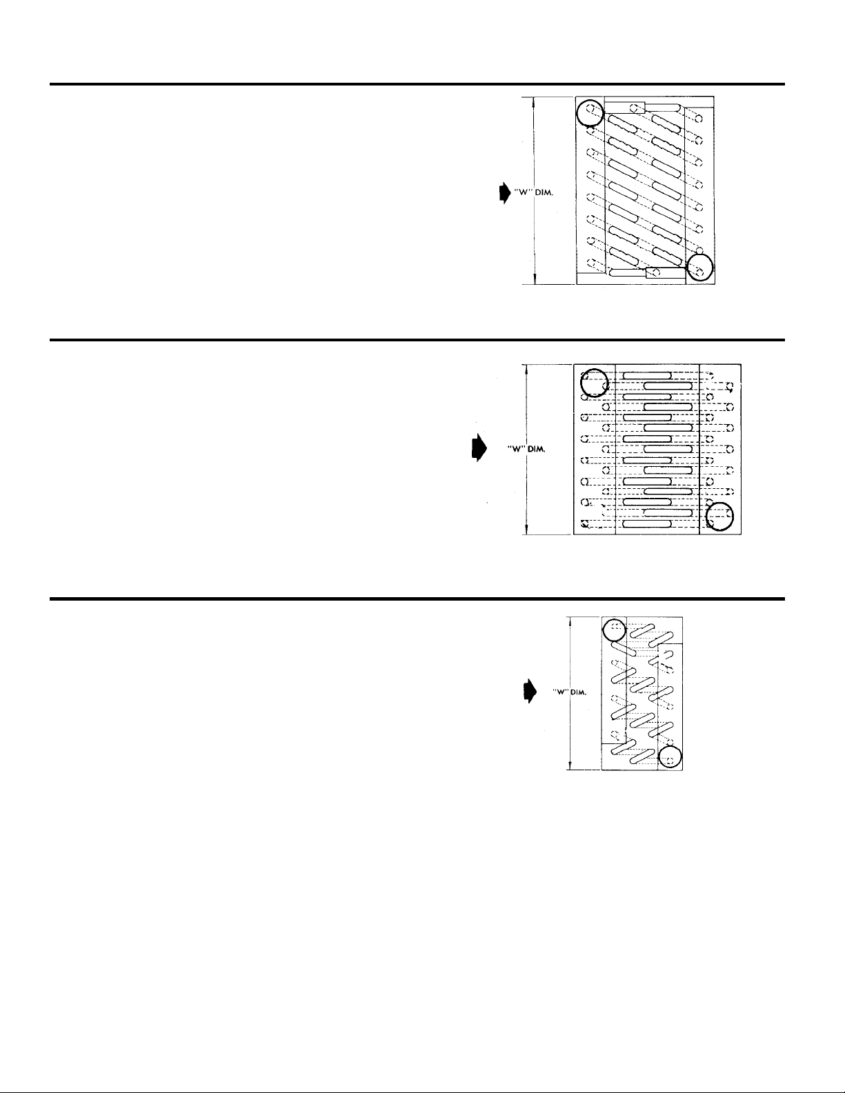
Type “KWS” Coils are counterflow, single serpentine
circuited to deliver absolute maximum performance.
With single serpentine coils every tube in the first row is
fed as indicated in the circuiting drawing on the right.
Type “KWS” Coils of two, four, six, eight and ten rows
deep are furnished with the supply and return connections on the same and of the coil.
TYPE “KWD” COILS
Type “KWD” Coils are designed for use in applications
that require high water quantities and low water pressure
drop.
“KWD” Coils are counterflow, double serpentine circuited
to maintain normal water velocities and low water
pressure drops. With double serpentine coils every tube in
the first and second rows are fed as shown in the
circuiting drawing on the eright.
AIR FLOW
6 ROW KWS CIRCUITING
HORIZONTAL OR VERTICAL AIR FLOW
AIR FLOW
Fourn and eight row coils have the supply and return
connections on the same end of the coil.
TYPE “KWH” COILS
Type “KWH” Coils are designed to produce high
capacity with limited water quantity. High capacity is
obtained from the counterflow half serpentine water
circuiting which gives higher water velocities.
With half serpentine coils every other tube in the first
row is fed as shown in the circuiting drawing on the
right.
All Type “KWH” Coils, regardless of row depth, have
both the supply and return connections on the same end
of the coil. When ordering KWH Coils, state vertical or
horizontal air flow as required.
8 ROW KWD CIRCUITING
HORIZONTAL OR VERTICAL AIR FLOW
AIR FLOW
4 ROW KWH CIRCUITING
HORIZONTAL AIR FLOW
- 4 -
Page 5
GENERAL INFORMATION
1. TOTAL BTU/HR
Total BTU/HR = 4.5 x CFM X (Total Heat Ent. Air - Total
Heat Lv. Air)
Where 4.5 = Density Std. Air x 60
Density Std. Air = .075 lbs./Cu. Ft.
Minutes/hr. = 60
5. WATER VELOCITY
1.144* x GPM
Water Velocity FPS =
*Use 1.326 for high pressure coils
Use 1.35 for .049 tube wall.
Number tubes fed
2. TOTAL BTU/HR
Total BTU/HR = 500 X GPM X (Lv. Water Temp. - Ent.
Water Temp.)
Where 500 = Lbs./Gal. X Min./Hr. X Specific Heat Water
Lbs./Gal. = 8.33
Min./Hr. = 60
Sp. Heat Water = 1
3. SENSIBLE BTU/HR
Sensible BTU/HR = 1.09 X CFM X (Ent. Air D.B. - Lv.
Air D.B.)
Where 1.09 = (sp. Ht. of air at 70°F.) X (Minutes/Hr.)
X Density Std. Air
Sp. Ht. of Air = .24 at 70°F.
Min./Hr. = 60
Density Std. Air = .075 Lbs./Cu. Ft.
4. LEAVING AIR DRY BULB TEMPERATURE
(a) Lv. Air D.B. = Ent. Air D.B. =
(b) Ly. Air D.B. = Lv. W.B. + (W.B. Depression Factor
X Initial W.B. Depression)
(c) Lv. Air D.B. = Lv. W.B. + Final W.B. Depression
Sens. BTU/HR
1.09 X CFM
Total BTU/HR
6. ROWS DEEP =
Where WSF = Wetted Surface Factor (From Figure 3 , Page 26)
MED = Log Mean Temperature Difference (From Table 5,
Page 24)
F
= Fin Series Correction Factor (From Table 7, Page 27
FR
Face Area. ( Sq. Ft.) x WSF x Med. x U x F
7. FACE AREA
F.A. =
CFM
Face Velocity (FPM)
8. FACE VELOCITY
F.V. =
CFM
Face Area (Sq. Ft.)
9. SENSIBLE TOTAL RATIO
S/T Ratio =
Sensible BTU/HR
Total BTU/-HR
10. TONS PER SQUARE FOOT OF FACE AREA
Tons/Sq. Ft. =
Total BTU/HR
Face Area (Sq. Ft.) X 12000
11. INITIAL W.B. DEPRESSION
Initial W.B. Depression = Entering D. B.- Entering W.B.
12. FINAL W.B. DEPRESSION
Final W.B. Depression = leaving D.B. - leaving W.B.
FR
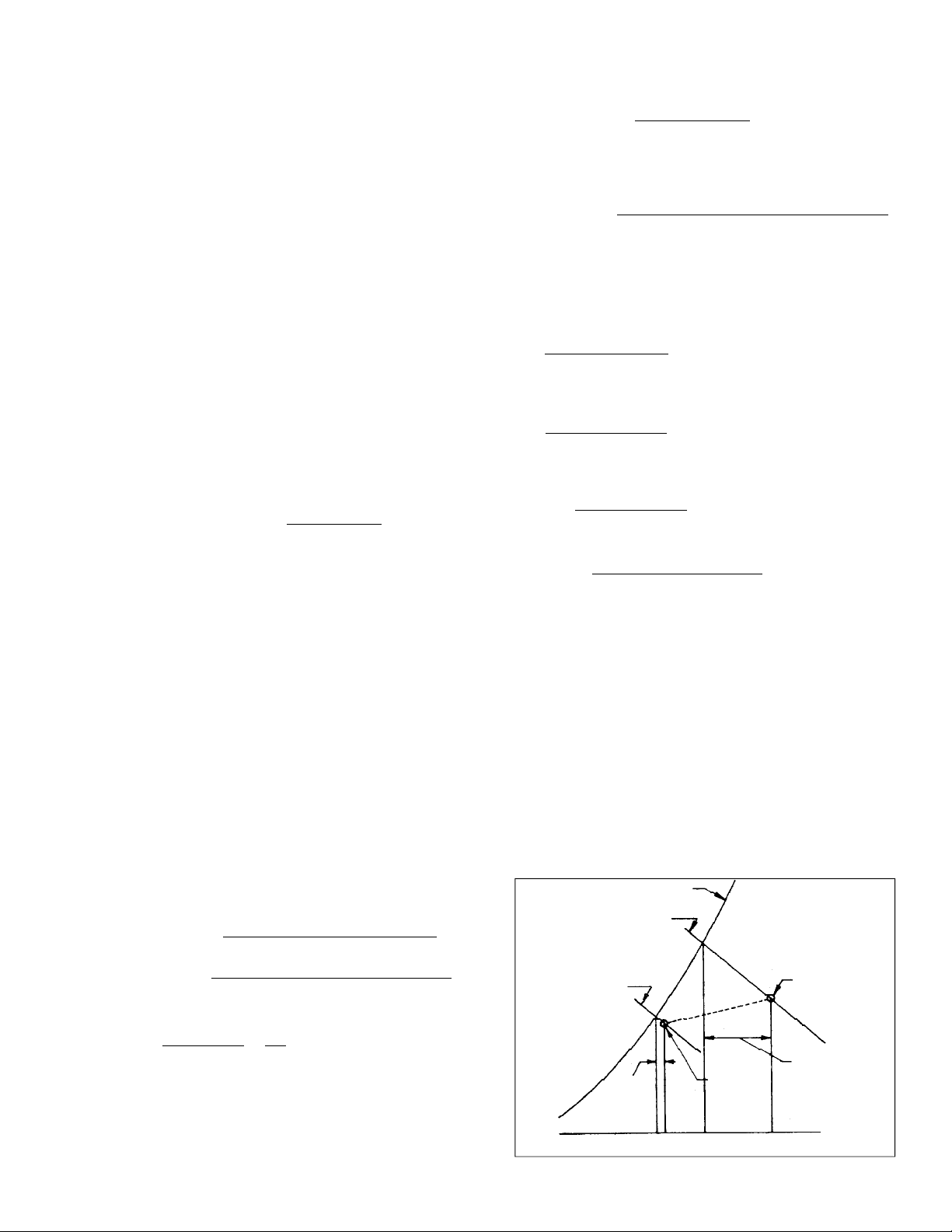
WET BULB DEPRESSION RATIO
Since both sensible and latent heat transfer are occurring
simultaneously between the surface of a chilled water
dehumidifying coil and the air passing over it, some coil
performance factor which establishes the relationship
between these two modes of heat transfer is required. For
this purpose KeepRite employs the wet bulb depression
factor which has the general acceptance of the finned tube
coil industry.
The wet bulb depression factor is the ratio of the leaving air
to entering air wet bulb depressions and is expressed as
follows:
Wet Bulb Depression
Factor (WBDF) =
Temp.
Temp.
For the example illustrated below, the Wet Bulb
Depression Factor Is:
WBDF =
80°F - 67°F = 13
61°F - 58°F 3
Since the wet bulb depression factor describes a heat
transfer relationship on the fin side of a coil only, it varies
with the air side heat transfer performance, the amount of
heat transfer surface and with the air velocity.The WB
depression factor is determined by laboratory tests of each
particular coil surface design. It should be noted that it is
Leaving Wet Bulb Depression
Entering Wet Bulb Depression
Lvg. Air D.B. - Lvg. Air W.B.
=
Ent. Air D.B. - Ent. Air W.B.
= .231
- 5 -
not influenced by the water flow rate. The wet bulb
depression factor does not apply to dry surface cooling
coils and is recommended for application only where the
sensible to total heat ratio is 0.9 or less. When the
sensible to total ratio is greater than 0.9, the fin surface
is essentially dry and the coil selection can be based on
dry surface to handle the total load.
Curves giving the wet bulb depression factors for
KeepRite Water Cooling Coils are shown on page 27.
SATURATION CURVE
ENTERING
67°F WET BULB
TEMP.
LEAVING
58°F WET BULB
TEMP.
LEAVING
DEPRESSION
W.B.
58 61 67 80
TEMPERATURE °F
AIR CONDITION
LEAVING COIL
AIR CONDITION
ENTERING COIL
ENTERING W.B.
DEPRESSION
Page 6
SYSTEM DESIGN AIR QUANITY DETERMINATION
In determining the CFM to circulate, the consulting
engineer normally considers: the volume of the conditioned
space, type of occupance or usage of the space, total load,
3. CFM for total load
CFM =
(4.5) (Enthalpy Ent. - Enthalpy Lvg.)
Total load
sensible load, ventilation requirements, air velocity in the
space (perceptability of air movement) and the sizes of
4. Air changes per hour (from A.S.H.R.A.E. Guide)
ducts required. Usually several of these factors affect the
determination of the CFM to be circulated; however, any
one factor may be controlling.
After determining the controlling factor or factors, the CFM
can be determined by any of the following methods or by
5. Ventilation requirements (from A.S.H.R.A.E.
Guide)
6. Fixed diffusion temperature (Ent. D.B - Lvg. D.B.)
(Usually 15° to 25°F.)
taking a compromise value between results obtained by
several of these methods.
1. CFM per ton (usually 400)
2. CFM for sensible load
CFM =
Sensible load (internal)
1.09 x (Ent. D.B. - lv. D.B.)
Although both total and sensible loads must be
considered in the final analysis, general practice is to
consider only the internal sensible load. Unless a
process is involved, usually the leaving dry bulb
temperature must be assumed and this is normally done
by actually assuming a diffusion temperature.
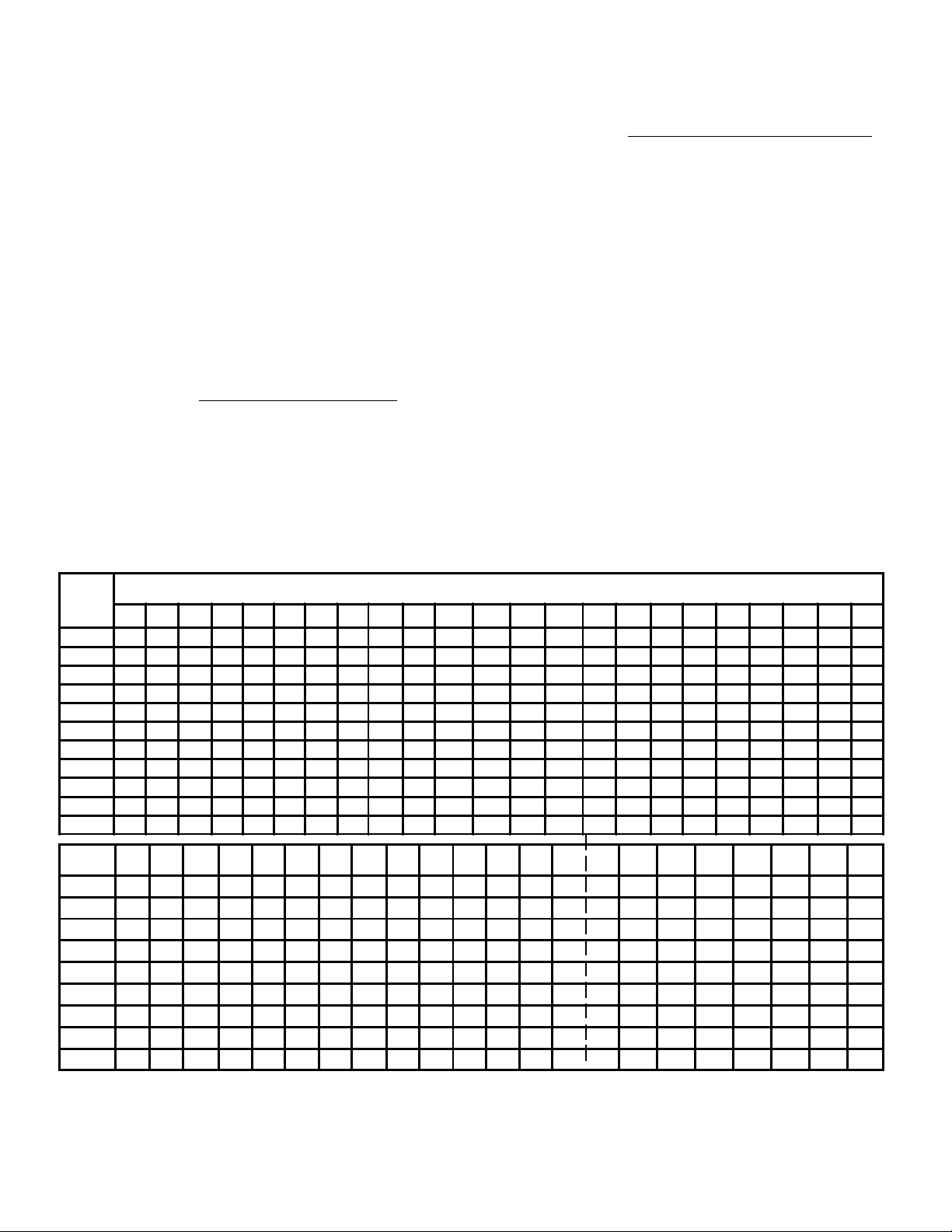
COIL SELECTION
SIZES
TABLE 1 - COIL SIZES - NOMINAL FACE AREA IN SQ. FT.
"W"
INCHES
12 15 18 21 24 27 30 33 36 39 42 45 48 51 54 57 60 63 66 69 72 75 78
6 .50 .62 .75 .87 1.00 1.13 1.25 1.38 1.50 1.63 1.75 1.88 2.0 2.1 2.2 2.4 2.5 2.6 2.7 2.9 3.0
9 .75 .94 1.12 1.31 1.50 1.69 1.87 2.06 2.25 2.44 2.62 2.81 3.0 3.2 3.4 3.6 3.7 3.9 4.1 4.3 4.5
12 1.00 1.25 1.50 1.75 2.00 2.25 2.50 2.75 3.00 3.25 3.50 3.75 4.0 4.3 4.5 4.8 5.0 5.3 5.5 5.8 6.0 6.3 6.5
15 1.56 1.87 2.19 2.50 2.81 3.12 3.44 3.75 4.06 4.37 4.68 5.0 5.3 5.6 5.9 6.2 6.6 6.9 7.2 7.5 7.8 8.1
18
2.25 2.62 3.00 3.37 3.75 4.12 4.50 4.87 5.25 5.62 6.0 6.4 6.7 7.1 7.5 7.9 8.2 8.6 9.0 9.4 9.7
21 3.06 3.50 3.94 4.37 4.82 5.25 5.69 6.12 6.56 7.0 7.4 7.9 8.3 8.7 9.2 9.6 10.1 10.5 10.9 11.4
24
4.00 4.50 5.00 5.50 6.00 6.50 7.00 7.50 8.0 8.5 9.0 9.5 10.0 10.5 11.0 11.5 12.0 12.5 13.0
27 5.06 5.62 6.19 6.75 7.32 7.87 8.44 9.0 9.6 10.1 10.7 11.2 11.8 12.4 12.9 13.5 14.1 14.6
30 6.25 6.88 7.50 8.12 8.75 9.37 10.0 10.6 11.2 11.9 12.5 13.1 13.7 14.4 15.0 15.6 16.2
33 7.56 8.25 8.94 9.62 10.30 11.0 11.7 12.4 13.1 13.7 14.4 15.1 15.8 16.5 17.2 17.9
36 9.00 9.75 10.50 11.20 12.0 12.7 13.5 14.2 15.0 15.7 16.5 17.2 18.0 18.7 19.5
NOMINAL TUBE LENGTH - NTL - (INCHES)
"W"
INCHES
In addition to the Finned Lengths listed above, KeepRite Refrigeration can furnish coils having any Finned Length
required up to 144 inches.
81 84 87 90 93 96 99 102 105 108 111 114 117 120 123 126 129 132 135 138 141 144
12 6.8 7.0 7.3 7.5 7.8 8.0 8.3 8.5 8.8 9.0 9.3 9.5 9.8 10.0
15 8.4 8.7 9.1 9.4 9.7 10.0 10.3 10.6 10.9 11.2 11.6 11.9 12.2 12.5
18 10.1 10.5 10.9 11.2 11.6 12.0 12.4 12.7 13.1 13.5 13.9 14.2 14.6 15.0 15.4 15.8
21 11.8 12.2 12.7 13.1 13.6 14.0 14.4 14.9 15.3 15.7 16.2 16.6 17.1 17.5 17.9 18.4 18.8 19.3
24 13.5 14.0 14.5 15.0 15.5 16.0 16.5 17.0 17.5 18.0 18.5 19.0 19.5 20.0 20.5 21.0 21.5 22.0 22.5 23.0 23.5 24.0
27 15.2 15.7 16.3 16.9 17.4 18.0 18.6 19.1 19.7 20.2 20.8 21.4 21.9 22.5 23.1 23.6 24.2 24.8 25.3 25.9 26.4 27.0
30 16.9 17.5 18.1 18.7 19.3 20.0 20.6 21.2 21.9 22.5 23.1 23.7 24.4 25.0 25.6 26.2 26.9 27.5 28.1 28.8 29.4 30.0
33 18.6 19.2 19.7 20.6 21.3 22.0 22.7 23.4 24.0 24.7 25.4 26.1 26.8 27.5 28.2 28.9 29.6 30.2 30.9 31.6 32.3 33.0
36 20.2 21.0 21.8 22.5 23.2 24.0 24.7 25.5 26.2 27.0 27.7 28.5 29.2 30.0 30.7 31.5 32.2 33.0 33.7 34.5 35.2 36.0
- 6 -
Page 7
COIL SELECTION
FIN SERIES CAPACITY CORRECTION FACTORS
TABLE No. 2 F
FD
ROWS
DEEP
4
6
8
For use with tons per sq. ft. from Direct Selection Table No. 4
70 80 100 120
.89
.91
.92
1.00
1.00
1.00
GENERAL CONSIDERATIONS
The cooling process should always be plotted on a
Psychrometric Chart (Page 34) to be sure that the desired
psychromatic changes are feasible.
When selecting a coil it should be remembered that if the
required leaving wet bulb temperature is met, the total load
is satisfied and vice versa. Also, when the required
leaving dry bulb temperature is met, the sensible load
requirement is satisfied.
A coil must meet both the total and sensible load
requirement in order to achieve the conditions desired in the
space to be cooled. Normally the total load capacity is
checked first, however, the leaving dry bulb should always
be checked. When the sensible total ratio is low, the coil
selection is normally controlled by the total load even though
the sensible cooling capacity may exceed the requirement.
In some cases if the leaving dry bulb temperature is too low,
re-heat may be required.
When the S/T ratio is high the coil selection is normally
controlled by the sensible cooling even though the total capacity may exceed that required by an appreciable amount.
If the total capacity far exceeds the requirement, a re-check
on the system should be made to be sure
sufficient system capacity is available.
MATCHING SENSIBLE-LATENT REQUIREMENTS
To more accurately meet sensible and total loads, 70 and
80 Fin Series Coils are recommended for lower S,/T ratios,
and 100 and 120 Fin Series for higher S/T ratios. For
normal S/T ratios, Fin Series 80 and 100 are recommended.
Normal cooling coil face velocities are from 400 to 600 FPM.
500 FPM is recommended for most applications. Moisture
carry-over tends to become a problem when face
velocities in excess of 600 FPM are used unless dry
FIN SERIES
1.12
1.09
1.07
1.22
1.17
1.13
cooling occurs or special consideration is given in
advance to moisture elimination. KeepRite Rippled Fin
Coils of any standard fin series when properly installed
and operated in the normal range, will not require
eliminator plates.
Water cooling coils are normally selected to have a tube
length of three to four times the header height for economy
in coil and duct costs. Coils of several different face
dimensions are usually available from Table 1 page 6 to
meet the required face area. Select the most desirable.
Water velocity in the tubes of approximately 3 to 4 FPS is
desirable to attain high heat transfer rates with a
reasonable water pressure drop.
Cooling coils should not normally exceed 36 inches high
(“W” dimension) as the condensate draining from the top
portion of the coil tends to load up on the lower portion of
the coil. On high latent loads a significant reduction in air
flow and performance may result. Where “W” dimension
exceeds 36" we recommend two or more coils banked
one above the other and installed in accordance with the
recommendations shown on page 32.
In general, the capacity of a Type KWH (half serpentine)
Coil is higher than a Type KWS (single serpentine) for the
same entering air and water conditions because of higher
water velocity. However, the water pressure drop is higher.
The capacity of a Type KWD (double serpentine) Coil is
lower than a Type KWS for the same entering air and water conditions because of lower water velocity.
However, the water pressure drop is lower.
When a coil has a high S /T Ratio, .9 or above, the coil
should be considered dry and selected as a dry coil.
- 7 -
Page 8
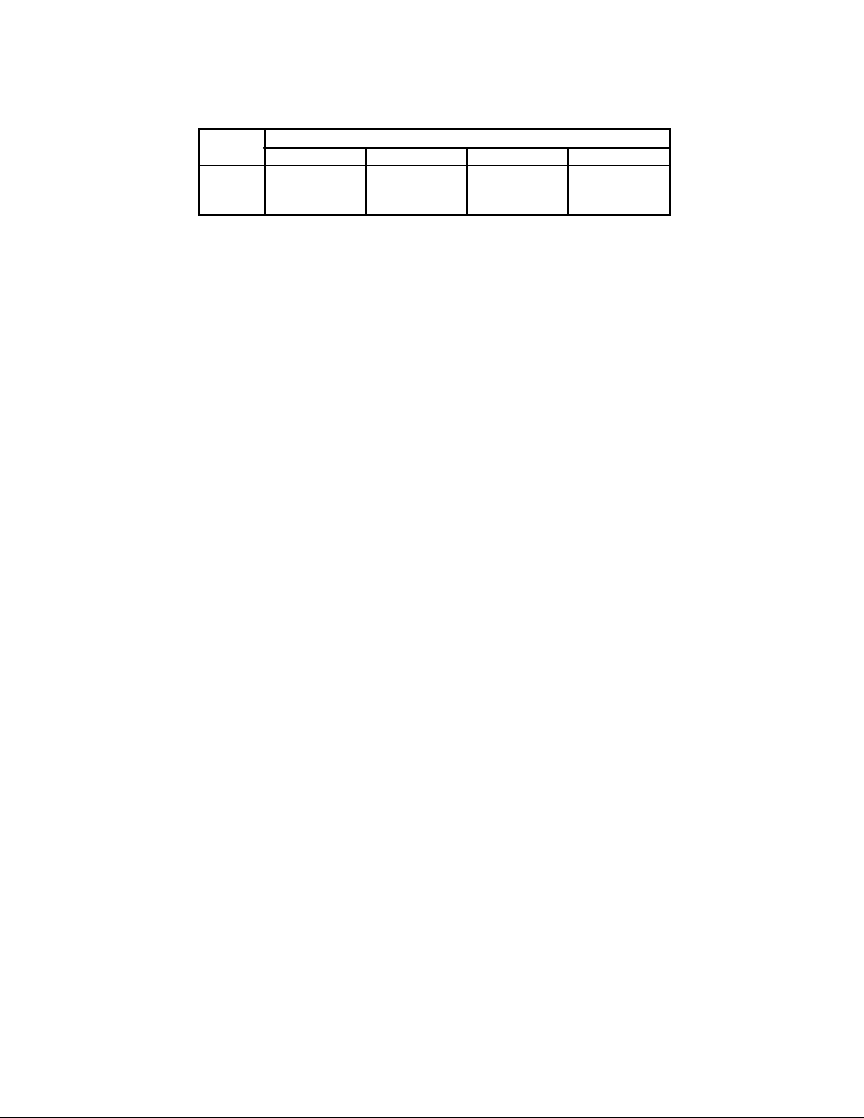
CONVERSION OF AIR VOLUME TO STANDARD AIR
FIGURE 1 - TEMPERATURE CONVERSION FACTOR
1.30
1.25
)
1
TEMPERATURE CONVERSION FACTOR (F
1.20
1.15
1.10
1.05
1.00
0.95
0.90
0.85
0.80
0.75
0.70
0.65
-50 -25 0 25 50 75 100 125 150 175 200 225 250 275 300 325 350
1.30
1.25
1.20
1.15
1.10
1.05
1.00
0.95
0.90
0.85
0.80
0.75
0.70
0.65
TEMPERATURE °F
When the specified air volume (CFM) is given at any temperature other than 70 °F or at any altitude other than sea level, these charts should be
used for correction before using the following capacity and friction tables (which are based on CFM @ standard air conditions).
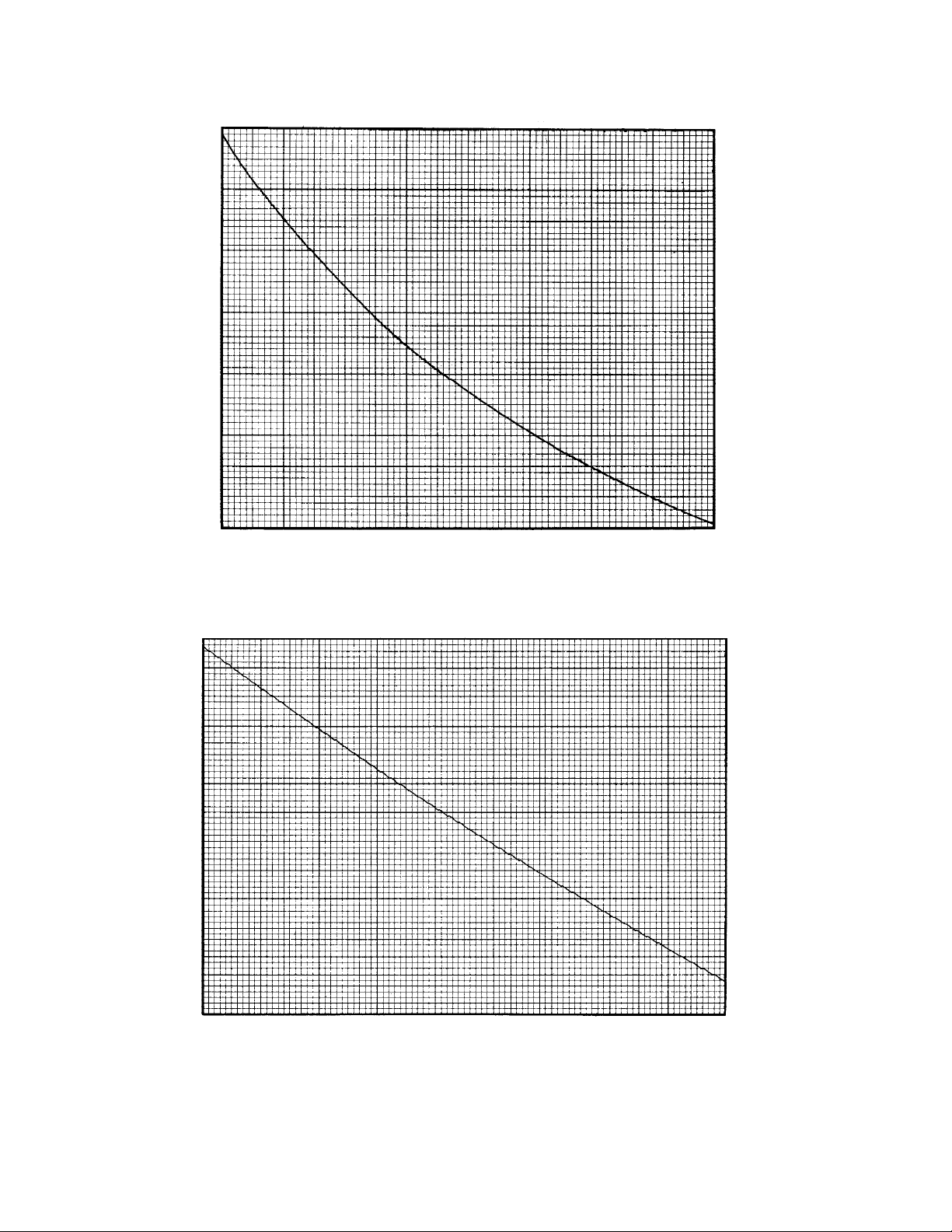
FIGURE 2 - ALTITUDE CONVERSION FACTOR
1.025
1.000
)
0.975
2
0.950
0.925
0.900
0.875
0.850
0.825
0.800
0.775
TEMPERATURE CONVERSION FACTOR (F
0.750
0.725
0.700
-500 0 500 1500 2500 3500 4500 5500 6500 7500 8500
ALTITUDE (FEET ABOVE SEA LEVEL)
1.025
1.000
0.975
0.950
0.925
0.900
0.875
0.850
0.825
0.800
0.775
0.750
0.725
0.700
Example: To convert 15,900 CFM of air at 94 °F and at 3,000
ft. altitude to standard conditions:
CFM of Std. Air
= CFM of specified Air x F1 x F
2
= 15,900 X 955 X .896 = 13,600
Where: F1 = Temperature conversion factor from Fig. 1.
F2 = Altitude conversion factor from Fig. 2.
- 8 -
Page 9

TOTAL HEAT
(Enthalpy)
TABLE No. 3 - BTU CONTENT OF 1 LB. OF DRY AIR WITH WATER VAPOR TO SATURATE IT†
(Standard Atmospheric Pressure 29.921” HG.)
WET
BULB
°F. *
35
36
37
38
39
.0 .1 .2 .3 .4 .5 .6 .7 .8 .9
13.01
13.44
13.87
14.32
14.77
13.05
13.48
13.92
14.36
14.82
13.09
13.52
13.96
14.41
14.86
13.14
13.57
14.01
14.45
14.91
TENTHS OF DEGREES
13.18
13.61
14.05
14.50
14.95
13.22
13.66
14.10
14.54
15.00
13.27
13.70
14.14
14.59
15.05
13.31
13.74
14.19
14.63
15.09
13.35
13.79
14.23
14.68
15.14
13.39
13.83
14.27
14.73
15.18
40
41
42
43
44
45
46
47
48
49
50
51
52
53
54
55
56
57
58
59
60
61
62
63
64
65
66
67
68
69
15.23
15.70
16.17
16.66
17.15
17.65
18.16
18.68
19.21
19.75
20.30
20.86
21.44
22.02
22.61
23.22
23.84
24.48
25.12
25.78
26.46
27.15
27.85
28.57
29.31
30.06
30.83
31.62
32.42
33.25
15.28
15.74
16.22
16.71
17.20
17.70
18.21
18.73
19.26
19.81
20.36
20.92
21.49
22.08
22.68
23.28
23.90
24.54
25.19
25.85
26.53
27.22
27.92
28.64
29.38
30.14
30.91
31.70
32.50
33.33
15.32
15.79
16.27
16.75
17.25
17.75
18.26
18.79
19.32
19.86
20.41
20.98
21.55
22.14
22.74
23.34
23.97
24.61
25.25
25.92
26.60
27.29
27.99
28.72
29.46
30.21
30.99
31.78
32.59
33.42
15.37
15.84
16.32
16.80
17.30
17.80
18.32
18.84
19.37
19.92
20.47
21.03
21.61
22.20
22.80
23.41
24.03
24.67
25.32
25.98
26.67
27.36
28.07
28.79
29.53
30.29
31.07
31.86
32.67
33.50
15.42
15.89
16.37
16.85
17.35
17.85
18.37
18.89
19.43
19.97
20.52
21.09
21.67
22.26
22.86
23.47
24.10
24.74
25.38
26.05
26.74
27.43
28.14
28.87
29.61
30.37
31.15
31.94
32.75
33.59
15.46
15.93
16.41
16.90
17.40
17.91
18.42
18.95
19.48
20.03
20.58
21.15
21.73
22.32
22.92
23.53
24.16
24.80
25.45
26.12
26.80
27.50
28.21
28.94
29.68
30.44
31.22
32.02
32.83
33.67
15.51
15.98
16.46
16.95
17.45
17.96
18.47
19.00
19.53
20.08
20.64
21.21
21.79
22.38
22.98
23.59
24.22
24.86
25.52
26.19
26.87
27.57
28.28
29.01
29.76
30.52
31.30
32.10
32.92
33.75
15.56
16.03
16.51
17.00
17.50
18.01
18.52
19.05
19.59
20.14
20.69
21.26
21.84
22.44
23.04
23.65
24.29
24.93
25.58
26.26
26.94
27.64
28.35
29.09
29.83
30.60
31.38
32.18
33.00
33.84
15.60
16.08
16.56
17.05
17.55
18.06
18.58
19.10
19.64
20.19
20.75
21.32
21.90
22.50
23.10
23.72
24.35
24.99
25.65
26.32
27.01
27.71
28.43
29.16
29.91
30.68
31.46
32.26
33.08
33.92
15.65
16.12
16.61
17.10
17.60
18.11
18.63
19.16
19.70
20.25
20.81
21.38
21.96
22.56
23.16
23.78
24.42
25.06
25.71
26.39
27.08
27.78
28.50
29.24
29.98
30.75
31.54
32.34
33.17
34.00
70
71
72
73
74
75
76
77
78
79
80
81
82
83
84
85
34.09
34.95
35.83
36.74
37.66
38.61
39.57
40.57
41.58
42.62
43.69
44.78
45.90
47.04
48.22
49.43
34.18
35.04
35.92
36.83
37.75
38.71
39.67
40.67
41.68
42.73
43.80
44.89
46.01
47.16
48.34
49.55
34.26
35.13
36.01
36.92
37.85
38.80
39.77
40.77
41.79
42.83
43.91
45.00
46.13
47.28
48.46
49.68
34.35
35.21
36.10
37.02
37.94
38.90
39.87
40.87
41.89
42.94
44.02
45.12
46.24
47.39
48.58
49.80
34.43
35.30
36.19
37.11
38.04
39.00
39.98
40.97
42.00
43.05
44.13
45.23
46.36
47.51
48.70
49.92
34.52
35.39
36.28
37.20
38.13
39.09
40.07
41.07
42.10
43.15
44.23
45.34
46.47
47.63
48.82
50.04
34.61
35.48
36.38
37.29
38.23
39.19
40.17
41.18
42.20
43.26
44.34
45.45
46.58
47.75
48.95
50.17
34.69
35.57
36.47
37.38
38.32
39.28
40.27
41.28
42.31
43.37
44.45
45.56
46.70
47.87
49.07
50.29
34.79
35.65
36.56
37.48
38.42
39.38
40.37
41.38
42.41
43.48
44.56
45.68
46.81
47.98
49.19
50.41
34.86
35.74
36.65
37.57
38.51
39.47
40.47
41.48
42.52
43.58
44.67
45.79
46.93
48.10
49.31
50.54
* Use wet bulb temperature only in determining total heat. † Compiled from data in ASHRAE GUIDE for 1967
- 9 -
Page 10

EXPLANATION FOR USING DIRECT SELECTION TABLES
I. PREFACE TO DIRECT SELECTION TABLE NO. 4
Direct Selection Table No. 4 contains a complete and
accurate compilation of data arranged for quick, easy
selection of water cooling coils to prepare or-meet a
specification.
The table covers the conditions normally encountered
in the air conditioning range for 80 Fin Series Coils.
Correction factors for Fin Series 70 100 and 120 are
shown in Table No. 2, page 7.
In many cases a slight adjustment in the CFM, face
area, water temperature rise, or percentage of fresh
air introduced can materially reduce the time required
to select a coil or group of coils.
Since Type KWS (single serpentine) Coils meet most
requirements, the majority of values shown in the
tables are for this coil type.
The color coil circuiting key for the Direct Selection
Tables is as follows: blue-half serpentine; white-single
serpentine; grey double serpentine.
See Dimensional Drawings, page 31 for complete coil
details.
Ill. LIMITATIONS OF CATALOG
1. All information contained in this catalog is based
on water as the cooling fluid. For fluids other
than water consult KeepRite Refrigeration.
2. Direct Selection Table No. 4 is based on 80 Fin
Series Coils. Applicable correction factors for 70,
100, and 120 Fin Series Coils are shown on
Table No. 2, page 7.
3. Interpolation between tables.
a. Interpolation between leaving wet bulb
temperatures should not be attempted as the
result will not be accurate.
b. Interpolation for performance values of Type
KWS, KWH and KWD is not possible, since
water velocities are vastly different. The
different type coils are indicated in the tables
by blue, grey and white.
c. Interpolation for 5 and 7 rows is permissible.
In preparing Direct Selection Tables, the use of
average correction factors has been avoided to
prevent multiplying of errors which could result in poor
coil selection. These tables could be within normally
accepted test laboratory accuracy.
II. VARIABLES COVERED IN DIRECT SELECTION
TABLE NO. 4
1. Values shown in Table No. 4 are for 80 Fin Series
Coils.
2. Entering wet bulb temperatures from 64°F through
70°F in 3°F increments.
3. Face velocities from 400 ft. per min. through 600
ft. per min. in 25 ft. per min. increments.
4. Entering water temperatures of 40, 45 and 50°F.
5. Water temperature rises of 8 and 10°F.
6. Finned lengths from 24" through 120" in 12"
increments.
d. Interpolation for entering water temperatures is
permissible.
e. Interpolation between water temperature rises
of 8 and 10 degrees is permissible.
f. Interpolation between entering wet bulb
temperature is permissible.
g. Interpolation between face velocities is
permissible.
h. Interpolation between finned length is
permissible.
i. Leaving wet bulb temperatures for other than 80
Fin Series Coils must be calculated.
4. Where use of Direct Selection Table No. 4 is not
possible the coil size may be calculated as shown
in Example Problems No. 1 and 2 on pages, 21,
22 and 23.
7. Row detpths of 4, 6, and 8.
8. Capacity in terms of tons per sq. ft. and leaving wet
bulb temperature.
5. Direct Selection Table No. 4 may not be used
when S/ T ratio is .90 or greater.
- 10 -
Page 11

EXPLANATION FOR USING DIRECT SELECTION TABLES
IV. USE OF DIRECT SELECTION TABLE NO.4
To determine row depth and finned length for a given
total load.
1. Before entering Direct Selection Table No. 4 it will be
necessary to know the following:
a. Coil face velocity. Calculate using Formula 8, or
assume 500 if unable to calculate or if not
specified.
b. Total tons per sq. ft.-Calculate using Formula 10
or leaving wet bulb temperature. If interpolation
of tables required, tons per sq. ft. must be
determined.
c. Leaving water temperature. Calculate using
Formula 2 when necessary.
2. Using the entering wet bulb temperature, entering
water temperature and leaving water temperature
find the proper page of Table No. 4.
3. Enter table at proper face velocity, read down to find
the value of tons per sq. ft. or leaving wet bulb
temperature most nearly meeting the requirement. It
is suggested that 4 row coils be checked first and if
insufficient the 6 and 8 rows be checked in turn.
Usually more than one selection is possible. Select
the coil having the fewest rows and the shortest
“NTL”. Since the coil height (“W” dimension) is
subsequently determined from the face area and
finned length keep the length height ratio in mind
when selecting the finned length from Table 4. Do
not overlook the possibility of using a higher or lower
fin series to more accurately match the capacity. In
many cases the higher fin series coil will reduce the
rows deep required. See Table 2, page 7 for fin
series correction factors to apply to the values of
tons per sq. ft. in Table No. 4.
5. Calculate leaving wet bulb temperature if not directly
readable from table.
6. Calculate the leaving dry bulb temperature using
Formula 3.
7. Determine water pressure drop as shown, page 29.
8. Determine air pressure drop as shown, page 29.
To determine capacity for a given coil.
1. Before entering table it will be necessary to know:
a. Coil face velocity. Calculate using Formula 8.
b. Coil “NTL”. Determine from Table 1, page 6.
c. Rows deep and fin series. (Would be
specified.)
d. Leaving water temperature-calculate using
Formula 2.
2. Using the entering wet bulb temperature entering water
temperature and leaving water temperature, find proper
page in Table No. 4.
3. Enter table in proper coil face velocity column, “NTL”
and row depth. Read capacity in terms of tons per sq.
ft. or leaving wet bulb temperature. If the given coil
is single serpentine and tables values are given for
KWH or KWD Type Coils, follow trial and error
procedure outlined in problems 1 and 2. For other than
80 Fin Series Coils multiply the value in tons per sq. ft.
from Table No. 4 by the fin series correction factor
(Table 2, page 7).
4. Calculate leaving wet bulb if not directly readable from
table.
5. Calculate leaving dry bulb temperature using
Formula 3.
4. Using the minimum required “NTL” and the minimum
coil face area find the minimum coil height
(“W” dimension) from Table 1, page 6.
6. Calculate water pressure drop as shown, page 30.
7. Calculate air pressure drop as shown, page 29.
- 11 -
Page 12

64°F, ENTERING AIR WET BULB, 40°F, ENTERING WATER, 48°F, LEAVING WATER
TABLE 4
Face Velocity
FPM
NTL Rows
Deep
24"
36"
48"
60"
72"
84"
96"
108"
120"
DIRECT SELECTION
400 425 450 475 500 525 550 575 600
Tons
Lvg.
Tons
Lvg.
Tons
Lvg.
Tons
Lvg.
Tons
Lvg.
Tons
Lvg.
Tons
Lvg.
Tons
Lvg.
Tons
per
W.B.
per
W.B.
per
W.B.
per
W.B.
per
W.B.
per
W.B.
per
W.B.
per
2
ft.
°F.
4
1.10
1.41
1.65
1.16
1.50
1.71
1.21
1.54
1.75
1.25
1.57
1.77
1.28
1.59
1.79
1.30
1.61
1.80
1.31
1.62
1.81
1.22*
1.56*
1.75*
1.23*
1.57*
1.77*
52.9
49.3
46.3
52.2
48.2
45.5
51.6
47.6
44.9
51.2
47.3
44.7
50.8
47.0
44.4
50.6
46.8
44.3
50.5
46.7
44.1
51.5*
47.4*
44.9*
51.4*
47.3*
44.7*
6
8
4
6
8
4
6
8
4
6
8
4
6
8
4
6
8
4
6
8
4
6
8
4
6
8
ft.
1.13
1.48
1.73
1.20
1.56
1.79
1.26
1.61
1.83
1.30
1.64
1.86
1.34
1.67
1.88
1.36
1.69
1.90
1.37
1.70
1.83*
1.29*
1.63*
1.85*
1.30*
1.64*
1.87*
2
°F.
53.3
49.5
46.5
52.6
48.7
45.8
51.9
48.0
45.3
51.5
47.6
45.0
51.1
47.3
44.7
50.8
47.0
44.5
50.7
46.9
45.3*
51.6*
47.8*
45.1*
51.5*
47.6*
44.9*
ft.
1.16
1.54
1.82
1.25
1.63
1.88
1.31
1.68
1.92
1.35
1.72
1.95
1.39
1.74
1.98
1.42
1.77
2.00
1.43
1.78
1.92*
1.34*
1.71*
1.94*
1.35*
1.72*
1.96*
2
°F.
53.7
51.6
46.7
52.8
48.8
46.0
52.2
48.3
45.5
51.8
47.8
45.2
51.4
47.6
44.8
51.1
47.2
44.6
50.9
47.1
45.5*
51.9*
47.9*
45.3*
51.8*
47.8*
45.1*
ft.
1.19
1.61
1.89
1.29
1.70
1.97
1.36
1.75
2.01
1.41
1.79
2.05
1.45
1.82
2.07
1.48
1.84
2.00*
1.49
1.76*
2.02*
1.40*
1.78*
2.04*
1.41*
1.80*
2.05*
2
°F.
54.0
49.9
47.0
53.1
49.0
46.1
52.4
48.5
45.7
51.9
48.1
45.3
51.5
47.8
45.1
51.2
47.5
45.8*
51.1
48.4*
45.6*
52.0*
48.2*
45.4*
51.9*
48.0*
45.3*
ft.
1.22
1.68
1.98
1.34
1.77
2.06
1.41
1.83
2.11
1.47
1.87
2.14
1.51
1.90
2.16
1.53
1.92
2.09*
1.55
1.83*
2.11*
1.46*
1.86*
2.13*
1.48*
1.88*
2.15*
2
°F.
54.3
50.1
47.1
53.2
49.2
46.3
52.6
48.6
45.8
52.0
48.2
45.5
51.7
47.9
45.3
51.5
47.7
46.0*
51.3
48.6*
45.8*
52.1*
48.3*
45.6*
52.0*
48.1*
45.4*
ft.
1.25
1.75
2.06
1.38
1.84
2.14
1.47
1.90
2.19
1.52
1.95
2.22
1.56
1.98
2.15*
1.59
1.90*
2.18*
1.47*
1.91*
2.20*
1.50*
1.93*
2.22*
1.52*
1.95*
2.24*
2
°F.
54.6
50.2
47.3
53.5
49.4
46.5
52.7
48.8
46.1
52.3
48.4
45.7
51.9
48.1
46.4*
51.6
48.8*
46.1*
52.7*
48.7*
45.9*
52.4*
48.5*
45.7*
52.3*
48.4*
45.5*
ft.
1.28
1.81
2.14
1.42
1.90
2.22
1.51
1.97
2.27
1.57
2.02
2.30
1.62
2.06
2.23*
1.65
1.95*
2.26*
1.52*
1.98*
2.28*
1.55*
2.01*
2.31*
1.57*
2.03*
2.33*
2
°F.
54.8
50.4
47.5
53.7
49.6
46.7
53.0
49.0
46.3
25.5
48.6
46.0
52.0
48.2
46.7*
51.8
49.2*
46.4*
52.9*
48.9*
46.2*
52.6*
48.7*
45.9*
52.5*
48.5*
45.7*
ft.
1.31
1.88
2.22
1.47
1.97
2.30
1.56
2.05
2.36
1.62
2.10
2.39
1.67
2.13
2.32*
1.70
2.01*
2.35*
1.57*
2.05*
2.37*
1.59*
2.08*
2.40*
1.62*
2.11*
2.42*
W.B.
2
°F.
55.0
50.5
47.6
53.8
49.8
46.9
53.1
49.1
46.4
52.6
48.7
46.1
52.2
48.4
46.7*
52.0
49.4*
46.5*
53.0*
49.1*
46.3*
52.9*
48.8*
46.0*
52.6*
48.6*
45.9*
per
ft.
1.34
1.94
2.29
1.51
2.04
2.39
1.60
2.12
2.45
1.67
2.17
2.48
1.72
2.03*
2.40*
1.76
2.08*
2.43*
1.61*
2.12*
2.46*
1.64*
2.15*
2.49*
1.67*
2.18*
2.50*
Lvg.
W.B.
2
°F.
55.2
50.7
47.8
54.0
49.9
47.0
53.3
49.2
46.5
52.8
48.8
46.2
52.4
49.9*
46.9*
52.1
49.6*
46.7*
53.2*
49.2*
46.4*
53.0*
49.0*
46.1*
52.8*
48.7*
46.0*
67°F, ENTERING AIR WET BULB, 40°F, ENTERING WATER, 48°F, LEAVING WATER
Face Velocity
FPM
NTL Rows
Deep
24"
36"
48"
60"
72"
84"
96"
108"
120"
4
6
8
4
6
8
4
6
8
4
6
8
4
6
8
4
6
8
4
6
8
4
6
8
4
6
8
( ) = KWS, (†) = KWH, (*) = KWD
Above capacities are based on Series 80 fin spacing. For other fin spacings see Capacity Correction Factors Table No. 2, page 7.
Note: Table may NOT be used when S T ratio is 90 or greater.
400 425 450 475 500 525 550 575 600
Tons
Lvg.
Tons
Lvg.
Tons
Lvg.
Tons
Lvg.
Tons
Lvg.
Tons
Lvg.
Tons
Lvg.
per
ft.
1.25
1.70
1.98
1.36
1.79
2.04
1.43
1.84
2.08
1.49
1.88
2.10
1.52
1.90
2.11
1.55
1.91
2.06*
1.56
1.84*
2.07*
1.49*
1.85*
2.08*
1.50*
1.86*
2.09*
W.B.
per
W.B.
per
W.B.
per
W.B.
per
W.B.
per
W.B.
2
°F.
55.1
50.0
46.5
53.9
48.9
45.7
53.1
48.2
45.2
52.4
47.7
44.9
52.1
47.5
44.8
51.7
47.4
45.5*
51.6
48.2*
45.3*
52.4*
48.1*
45.2*
52.3*
48.0*
45.0*
2
t.
1.32
1.77
2.07
1.42
1.87
2.14
1.49
1.93
2.18
1.55
1.97
2.20
1.59
1.99
2.22
1.62
2.00
2.17*
1.63
1.92*
2.18*
1.55*
1.93*
2.19*
1.57*
1.94*
2.20*
°F.
55.2
50.4
46.9
54.1
49.3
46.1
53.4
48.5
45.5
52.8
48.1
45.3
52.4
47.8
45.1
52.0
47.7
45.7*
51.9
48.7*
45.5*
52.8*
48.5*
45.4*
52.6*
48.4*
45.3*
ft.
1.38
1.85
2.17
1.49
1.95
2.24
1.55
2.01
2.28
1.62
2.05
2.31
1.66
2.07
2.33
1.68
2.08
2.27*
1.69
2.00*
2.28*
1.61*
2.02*
2.30*
1.63*
2.03*
2.31*
2
°F.
55.4
50.6
47.9
54.3
49.5
46.3
53.7
48.9
45.9
53.0
48.4
45.5
52.6
48.2
45.3
52.4
48.2
46.0*
52.3
49.0*
45.9*
53.1*
48.8*
45.6*
52.9*
48.7*
45.5*
ft.
1.44
1.93
2.26
1.55
2.03
2.34
1.61
2.10
2.38
1.68
2.14
2.41
1.71
2.16
2.36*
1.74
2.17
2.37*
1.76
2.09*
2.39*
1.67*
2.11*
2.41*
1.69*
2.12*
2.42*
2
°F.
55.5
50.8
47.5
54.5
49.8
46.6
53.9
49.1
46.2
53.3
48.7
45.8
53.0
48.5
46.3*
52.7
48.4
46.3*
52.5
49.2*
46.1*
53.4*
49.0*
45.8*
53.2*
48.9*
45.7*
ft.
1.50
2.01
2.35
1.61
2.12
2.44
1.69
2.18
2.49
1.75
2.22
2.53
1.79
2.25
2.46*
1.81
2.16*
2.48*
1.72*
2.18*
2.50*
1.74*
2.20*
2.52*
1.75*
2.22*
2.53*
2
°F.
55.6
51.1
47.8
54.7
50.0
46.9
54.0
49.5
46.3
53.4
49.0
45.9
53.1
48.8
46.7*
52.9
49.7*
46.4*
53.7*
49.4*
46.3*
53.5*
49.3*
46.0*
53.4*
49.1*
45.9*
ft.
1.56
2.08
2.44
1.68
2.20
2.54
1.76
2.27
2.59
1.81
2.31
2.62
1.85
2.34
2.55*
1.87
2.25*
2.58*
1.79*
2.27*
2.60*
1.80*
2.29*
2.62*
1.82*
2.31*
2.63*
2
°F.
55.8
51.3
48.0
54.8
50.3
46.1
54.1
49.6
46.6
53.7
49.2
46.3
53.3
48.9
47.0*
53.2
49.8*
46.7*
53.8*
49.6*
46.5*
53.8*
49.4*
46.3*
53.6*
49.2*
46.2*
per
ft.
1.62
2.16
2.53
1.74
2.28
2.64
1.82
2.35
2.70
1.88
2.40
2.74
1.92
2.43
2.65*
1.94
2.33*
2.68*
1.85*
2.35*
2.70*
1.87*
2.38*
2.72*
1.89*
2.40*
2.73*
2
W.B.
°F.
55.9
51.5
48.2
54.9
50.5
47.3
54.3
49.9
46.7
53.8
49.4
46.3
53.5
49.1
47.2*
53.3
50.0*
46.9*
54.1*
49.9*
46.7*
53.9*
49.6*
46.5*
53.7*
49.4*
46.4*
Tons
per
ft.
1.68
2.24
2.62
1.80
2.36
2.73
1.88
2.44
2.80
1.94
2.49
2.84
1.98
2.52
2.75*
2.01
2.41*
2.78*
1.91*
2.43*
2.80*
1.93*
2.46*
2.83*
1.95*
2.48*
2.84*
W.B.
2
47.3*
50.3*
47.1*
54.3*
50.1*
46.9*
54.1*
49.8*
45.6*
53.9*
49.7*
46.5*
- 12 -
Lvg.
°F.
56.0
51.6
48.5
55.1
50.7
47.5
54.5
50.0
46.9
54.0
49.6
46.5
53.7
49.3
53.5
Tons
per
ft.
1.73
2.31
2.71
1.85
2.44
2.83
1.94
2.52
2.90
2.00
2.57
2.94
2.04
2.61
2.84*
2.07
2.50*
2.88*
1.96*
2.52*
2.91*
1.98*
2.55*
2.94*
2.00*
2.57*
2.95*
Lvg.
W.B.
2
°F.
56.1
51.8
48.7
55.3
50.8
47.6
54.6
50.2
47.1
54.2
49.8
46.7
53.9
49.5
47.5*
53.6
50.3*
47.2*
54.5*
50.2*
46.9*
54.3*
49.9*
46.7*
54.2*
49.8*
46.6*
Page 13

70°F, ENTERING AIR WET BULB, 40°F, ENTERING WATER, 48°F, LEAVING WATER
TABLE 4 - cont.
Face Velocity
FPM
NTL Rows
Deep
24"
36"
48"
60"
72"
84"
96"
108"
120"
4
6
8
4
6
8
4
6
8
4
6
8
4
6
8
4
6
8
4
6
8
4
6
8
4
6
8
400 425 450 475 500 525 550 575 600
Tons
per
ft.
1.51
2.00
2.31
1.61
2.10
2.37
1.68
2.16
2.41
1.73
2.19
2.44
1.77
2.20
2.38*
1.80
2.13*
2.39*
1.82
2.16*
2.41*
1.77*
2.18*
2.42*
1.78*
2.19*
2.43*
Lvg.
Tons
Lvg.
Tons
Lvg.
Tons
Lvg.
Tons
Lvg.
W.B.
per
W.B.
per
W.B.
per
W.B.
2
°F.
56.3
50.8
47.0
55.2
49.6
46.3
54.4
48.9
45.7
53.9
48.5
45.3
53.4
48.4
46.1*
53.1
49.2*
46.0*
52.9
48.9*
45.7*
53.4*
48.6*
45.6*
53.3*
48.5*
45.4*
ft.
1.58
2.10
2.44
1.68
2.20
2.51
1.76
2.26
2.55
1.81
2.30
2.58
1.86
2.31
2.51*
1.89
2.24*
2.53*
1.91
2.26*
2.54*
1.84*
2.28*
2.55*
1.85*
2.29*
2.57*
2
°F.
56.5
51.1
47.1
55.5
50.0
46.3
54.7
49.3
45.9
54.2
48.8
45.5
53.7
48.7
46.3*
53.3
49.5*
46.1*
53.1
49.3*
46.0*
53.9*
49.1*
45.9*
53.8*
48.9*
45.6*
ft.
1.65
2.19
2.57
1.76
2.30
2.64
1.84
2.37
2.68
1.90
2.41
2.71
1.94
2.42
2.63*
1.98
2.35*
2.65*
2.00
2.37*
2.67*
1.91*
2.39*
2.69*
1.92*
2.40*
2.70*
2
°F.
56.7
51.4
47.3
55.7
50.3
46.5
54.9
49.5
46.1
54.3
49.1
45.7
54.0
49.0
46.6*
53.6
49.7*
46.4*
53.4
49.5*
46.2*
54.3*
49.3*
46.0*
54.1*
49.2*
45.8*
ft.
1.72
2.29
2.68
1.83
2.40
2.76
1.92
2.47
2.81
1.98
2.52
2.84
2.03
2.54
2.76*
2.06
2.45*
2.78*
2.08
2.48*
2.80*
1.98*
2.50*
2.82*
1.99*
2.51*
2.83*
2
°F.
56.9
51.6
47.6
55.9
50.5
46.8
55.1
49.8
46.2
54.6
49.3
45.9
54.1
49.1
46.8*
53.8
50.0*
46.6*
53.6
49.7*
46.4*
54.6*
49.5*
46.2*
54.5*
49.4*
46.1*
per
ft.
1.78
2.38
2.79
1.91
2.50
2.88
2.00
2.57
2.93
2.06
2.63
2.96
2.11
2.66
2.88*
2.14
2.54*
2.91*
2.04*
2.57*
2.93*
2.05*
2.60*
2.95*
2.06*
2.61*
2.96*
2
W.B.
°F.
57.2
51.9
48.0
56.1
50.8
47.1
55.3
50.1
46.6
54.8
49.6
46.3
54.3
49.3
47.1*
54.1
50.4*
46.8*
55.0*
50.1*
46.6*
54.9*
49.8*
46.4*
54.8*
49.8*
46.3*
Tons
per
ft.
1.84
2.47
2.90
1.98
2.59
3.00
2.07
2.67
3.06
2.14
2.73
2.97*
2.19
2.60*
3.00*
2.21
2.64*
3.03*
2.11*
2.67*
3.06*
2.12*
2.70*
3.08*
2.13*
2.72*
3.09*
2
Lvg.
W.B.
°F.
57.4
52.2
48.3
56.3
51.1
47.3
55.6
50.4
46.8
55.0
49.8
47.6*
54.6
51.0*
47.3*
54.4
50.7*
47.0*
55.3*
50.4*
46.7*
55.2*
50.1*
46.6*
55.1*
49.9*
46.4*
To
ns
per
ft.
1.91
2.56
3.01
2.05
2.69
3.11
2.14
2.77
3.18
2.20
2.83
3.08*
2.25
2.69*
3.11*
2.27
2.74*
3.14*
2.17*
2.77*
3.17*
2.19*
2.80*
3.19*
2.20*
2.82*
3.21*
Lvg.
Tons
per
ft.
1.97
2.65
3.12
2.13
2.79
3.23
2.23
2.87
3.30
2.30
2.92
3.19*
2.34
2.79*
3.23*
2.20*
2.84*
3.26*
2.24*
2.87*
3.29*
2.26*
2.90*
3.32*
2.28*
2.92*
3.33*
Lvg.
W.B.
2
°F.
57.7
52.6
48.8
56.6
51.5
47.8
55.9
50.9
47.2
55.3
50.5
48.2*
55.0
51.5*
47.8*
56.1*
51.1*
47.6*
55.8*
50.9*
47.3*
55.6*
50.6*
47.0
55.5*
50.5*
46.9*
W.B.
2
°F.
57.6
52.4
48.5
56.5
51.3
47.6
55.8
50.6
47.0
55.3
50.1
47.9*
54.9
51.3*
47.6*
54.8
50.9*
47.4*
55.6*
50.6*
47.0*
55.4*
50.4*
46.9*
55.2*
50.2*
46.7*
Tons
per
ft.
2.03
2.74
3.23
2.20
2.88
3.34
2.30
2.96
3.41
2.37
3.00
3.30*
2.42
2.88*
3.34*
2.26*
2.93*
3.37*
2.30*
2.97*
3.40*
2.33*
3.00*
3.43*
2.35*
3.02*
2.44*
Lvg.
W.B.
2
°F.
57.9
52.8
48.9
56.7
51.7
48.0
56.0
51.1
47.4
55.5
50.8
48.4*
55.2
51.7*
48.0*
56.3*
51.4*
47.8*
56.0*
51.0*
47.5*
55.8*
50.8*
47.3*
55.7*
50.6*
47.2*
64°F, ENTERING AIR WET BULB, 45°F, ENTERING WATER, 53°F, LEAVING WATER
Face Velocity
FPM
NTL Rows
Deep
24"
36"
48"
60"
72"
84"
96"
108"
120"
4
6
8
4
6
8
4
6
8
4
6
8
4
6
8
4
6
8
4
6
8
4
6
8
4
6
8
400 425 450 475 500 525 550 575 600
Tons
Lvg.
Tons
Lvg.
Tons
Lvg.
Tons
Lvg.
Tons
Lvg.
Tons
Lvg.
Tons
Lvg.
per
ft.
.91†
1.04
1.25
.83
1.12
1.32
.89
1.17
1.36
.93
1.20
1.38
.96
1.23
1.40
.98
1.25
1.42
1.00
1.26
1.43
1.02
1.27
1.44
1.03
1.28
1.38*
W.B.
per
W.B.
per
W.B.
per
W.B.
per
W.B.
per
W.B.
2
55.0†
53.6
51.2
55.9
52.7
50.4
55.3
52.1
49.9
54.8
51.8
49.6
54.5
51.4
43.9
54.3
51.2
43.9
54.0
51.1
49.0
53.8
50.9
48.9
53.7
50.8
49.6*
°F.
2
.
.95†
1.09
1.31
.86
1.17
1.38
.92
1.22
1.42
.97
1.25
1.45
1.00
1.28
1.47
1.02
1.30
1.49
1.04
1.32
1.50
1.06
1.33
1.44*
1.07
1.34
1.45*
°F.
55.2†
53.7
51.4
56.1
52.9
50.6
55.5
52.4
50.2
55.0
52.0
49.8
54.7
51.7
43.9
54.5
51.5
49.4
54.3
51.3
49.3
54.1
51.2
49.9*
54.0
51.1
49.8*
2
ft.
.98†
1.13
1.37
.89
1.22
1.44
.96
1.28
1.49
1.01
1.31
1.51
1.04
1.34
1.54
1.06
1.36
1.56
1.08
1.38
1.57
1.10
1.39
1.50*
1.11
1.32*
1.51*
°F.
55.5†
54.0
51.6
56.3
53.1
50.8
55.6
52.5
50.3
55.2
52.2
50.1
54.9
51.9
49.8
54.7
51.7
49.6
54.5
51.5
49.5
54.3
51.4
50.2*
54.2
52.0*
50.1*
ft.
1.01†
1.18
1.43
.92
1.27
1.51
1.00
1.33
1.55
1.05
1.37
1.58
1.08
1.39
1.61
1.10
1.41
1.63
1.13
1.43
1.65
1.15
1.44
1.57*
1.16
1.37*
1.58*
2
°F.
55.7†
54.1
51.7
56.5
53.3
50.9
55.8
52.7
50.5
55.3
52.3
50.2
55.0
52.1
49.9
54.9
51.9
49.7
54.3
51.7
49.5
54.4
51.6
50.3*
54.3
52.3*
50.2*
ft.
1.04†
1.22
1.48
.96
1.32
1.57
1.03
1.39
1.62
1.09
1.42
1.65
1.12
1.45
1.68
1.15
1.47
1.70
1.17
1.49
1.63*
1.19
1.42*
1.65*
1.20
1.43*
1.66*
2
°F.
55.9†
54.3
52.0
56.6
53.4
51.1
56.0
52.8
50.7
55.5
52.5
50.4
55.2
52.2
50.1
54.9
52.1
49.9
54.7
51.9
50.6*
54.6
52.5*
50.4*
54.5
52.4*
50.3*
ft.
1.07†
1.27
1.54
.99
1.38
1.63
1.07
1.44
1.68
1.12
1.47
1.72
1.16
1.50
1.75
1.19
1.53
1.78
1.22
1.55
1.69*
1.24
1.47*
1.71*
1.25
1.48*
1.72*
2
°F.
56.1†
54.4
52.1
56.7
53.5
51.3
56.1
53.0
50.8
55.7
52.7
50.5
55.3
52.4
50.2
55.1
52.2
49.9
54.8
52.0
50.8*
54.7
52.7*
50.6*
54.6
52.6*
50.5*
per
ft.
1.11†
1.31
1.60
1.02
1.43
1.69
1.10
1.50
1.75
1.16
1.53
1.79
1.20
1.56
1.82
1.23
1.59
1.85
1.26
1.61
1.76*
1.28
1.53*
1.78*
1.29
1.54*
1.79*
2
W.B.
°F.
56.1†
54.6
52.2
56.8
53.6
51.4
56.2
53.0
50.9
55.7
52.8
50.8
55.4
52.5
50.3
55.2
52.3
50.1
55.0
52.1
50.8*
54.8
52.8*
50.7*
54.7
52.7*
50.6*
Tons
per
ft.
.93
1.35
1.66
1.05
1.48
1.75
1.14
1.56
1.81
1.20
1.59
1.85
1.24
1.62
1.89
1.27
1.64
1.80*
1.30
1.66
1.82*
1.32
1.58*
1.84*
1.33
1.59*
1.85*
Lvg.
Tons
per
ft.
.96
1.39
1.72
1.08
1.53
1.81
1.17
1.60
1.88
1.24
1.64
1.92
1.28
1.67
1.96
1.31
1.70
1.86*
1.34
1.61*
1.88*
1.23*
1.63*
1.90*
1.25*
1.65*
1.91*
Lvg.
W.B.
2
°F.
57.9
54.8
52.4
57.0
53.8
51.7
56.4
53.3
51.2
55.9
53.0
50.8
55.6
52.8
50.5
55.4
52.5
51.3*
55.2
53.2*
51.2*
56.0*
53.1*
51.0*
55.9*
52.9*
50.9*
W.B.
2
°F.
57.8
54.7
52.3
56.9
53.7
51.6
56.3
53.1
51.1
55.8
52.9
50.8
55.6
52.6
50.4
55.3
52.5
51.2*
55.1
52.3
51.0*
55.0
52.9*
50.8*
54.9
52.9*
54.8*
( ) = KWS, (†) = KWH, (*) = KWD
Above capacities are based on Series 80 fin spacing. For other fin spacings see Capacity Correction Factors Table No. 2, page 7.
Note: Table may NOT be used when S T ratio is 90 or greater.
- 13 -
Page 14

67°F, ENTERING AIR WET BULB, 45°F, ENTERING WATER, 53°F, LEAVING WATER
TABLE 4 - cont.
Face Velocity
FPM
Deep
4
6
8
4
6
8
4
6
8
4
6
8
4
6
8
4
6
8
4
6
8
8
8
Tons
per
ft.
1.14
1.32
1.57
1.05
1.41
1.64
1.12
1.46
1.68
1.16
1.49
1.71
1.19
1.52
1.73
1.21
1.54
1.74
1.23
1.55
1.68*
1.24
1.49*
1.70*
1.25
1.50*
1.71*
2
NTL Rows
24"
36"
48"
60"
72"
84"
96"
108"46
120"46
400 425 450 475 500 525 550 575 600
Lvg.
Tons
Lvg.
Tons
Lvg.
Tons
Lvg.
Tons
Lvg.
Tons
Lvg.
Tons
Lvg.
Tons
Lvg.
W.B.
°F.
56.3
54.3
51.5
57.2
53.3
50.7
56.5
52.8
50.2
56.1
52.4
49.8
55.7
52.1
49.6
55.5
51.8
49.5
55.3
51.7
50.2*
55.2
52.4*
50.1*
55.1
52.3*
49.8*
per
ft.
.98
1.38
1.65
1.10
1.47
1.72
1.16
1.53
1.76
1.20
1.56
1.79
1.23
1.59
1.81
1.26
1.61
1.82
1.28
1.62
1.76*
1.29
1.54*
1.78*
1.30
1.56*
1.79*
W.B.
per
W.B.
per
W.B.
per
W.B.
per
W.B.
per
W.B.
2
°F.
58.3
54.6
51.7
57.4
53.6
50.9
56.8
53.0
50.5
56.4
52.7
50.2
56.1
52.3
49.9
55.8
52.1
49.8
55.6
52.0
50.5*
55.5
52.9*
50.3*
55.4
52.7*
50.2*
ft.
1.02
1.43
1.72
1.14
1.53
1.80
1.21
1.59
1.84
1.25
1.63
1.88
1.28
1.66
1.90
1.31
1.68
1.83*
1.33
1.60*
1.85*
1.34
1.61*
1.86*
1.27*
1.63*
1.87*
2
°F.
58.7
54.9
52.0
57.6
53.9
51.1
56.9
53.3
50.7
56.6
52.9
50.3
56.3
52.6
50.1
56.0
52.4
50.8*
55.8
53.2*
50.6*
55.8
53.1*
50.5*
56.4*
52.9*
50.4*
ft.
1.06
1.49
1.79
1.18
1.59
1.88
1.26
1.65
1.93
1.30
1.69
1.97
1.33
1.72
1.99
1.36
1.74
1.91*
1.39
1.66*
1.93*
1.40
1.68*
1.94*
1.32*
1.69*
1.95*
2
°F.
58.8
55.0
52.2
57.8
54.1
51.3
57.1
53.6
50.8
56.7
53.2
50.4
56.5
52.9
50.2
56.2
52.7
51.1*
56.0
53.5*
50.8*
55.9
53.3*
50.7*
56.6*
53.2*
50.6*
2
ft.
1.10
1.55
1.87
1.22
1.66
1.96
1.30
1.72
2.01
1.34
1.76
2.05
1.38
1.79
2.07
1.41
1.81
1.99*
1.44
1.73*
2.01*
1.45
1.75*
2.03*
1.37*
1.76*
2.04*
°F.
59.0
55.2
52.4
58.0
54.2
51.5
57.3
53.7
51.1
57.0
53.4
50.7
56.7
53.1
50.1
56.4
52.9
51.2*
56.2
53.6*
51.1*
56.1
53.4*
50.9*
56.7*
53.4*
50.8*
ft.
1.14
1.60
1.94
1.27
1.72
2.04
1.35
1.78
2.10
1.39
1.83
2.13
1.43
1.86
2.16
1.46
1.88
2.07*
1.49
1.79*
2.09*
1.40*
1.81*
2.11*
1.42*
1.82*
2.12*
2
°F.
59.1
55.4
52.6
58.1
54.4
51.7
57.4
53.9
51.2
57.1
53.5
50.9
56.8
53.3
50.6
56.6
53.1
51.4*
56.3
53.8*
51.3*
57.1*
53.7*
51.1*
56.9*
53.6*
51.0*
ft.
1.18
1.66
2.02
1.31
1.78
2.13
1.39
1.85
2.18
1.44
1.89
2.22
1.49
1.92
2.12*
1.52
1.84*
2.15*
1.54
1.86*
2.17*
1.45*
1.88*
2.19*
1.47*
1.89*
2.20*
2
°F.
59.2
55.6
52.7
58.2
54.6
51.8
57.6
54.1
51.3
57.3
53.7
51.0
56.9
53.5
51.8*
56.6
54.1*
51.6*
56.5
54.0*
51.4*
57.2*
53.8*
51.3*
51.0*
53.7*
51.1*
per
ft.
1.22
1.71
2.09
1.35
1.84
2.21
1.44
1.91
2.27
1.49
1.96
2.30
1.54
1.99
2.21*
1.57
1.90*
2.23*
1.59
1.92*
2.25*
1.50*
1.94*
2.27*
1.52*
1.95*
2.29*
2
W.B.
°F.
59.3
55.7
52.8
58.4
54.8
51.9
57.7
54.2
51.4
57.4
53.9
51.1
57.0
53.6
51.9*
56.8
54.3*
51.7*
56.6
54.2*
51.6*
57.3*
54.0*
51.4*
57.1*
53.9*
51.2*
Tons
per
2
ft.
1.26
1.77
2.16
1.40
1.90
2.29
1.49
1.98
2.35
1.54
2.03
2.38
1.59
2.06
2.29*
1.62
1.97*
2.31*
1.62
1.99*
2.33*
1.55*
2.01*
2.35*
1.57*
2.02*
2.37*
Lvg.
W.B.
°F.
59.3
55.9
53.0
58.4
55.0
52.0
57.8
54.3
51.5
57.5
53.9
51.3
57.1
53.7
52.0*
56.9
54.4*
51.8*
56.7
54.3*
51.7*
57.4*
54.1*
51.5*
57.2*
54.0*
51.4*
70°F, ENTERING AIR WET BULB, 45°F, ENTERING WATER, 53°F, LEAVING WATER
Face Velocity
FPM
NTL Rows
Deep
24"
36"
48"
60"
72"
84"
96"
108"
120"
4
6
8
4
6
8
4
6
8
4
6
8
4
6
8
4
6
8
4
6
8
4
6
8
4
6
8
( ) = KWS, (†) = KWH, (*) = KWD
Above capacities are based on Series 80 fin spacing. For other fin spacings see Capacity Correction Factors Table No. 2, page 7.
Note: Table may NOT be used when S T ratio is 90 or greater.
400 425 450 475 500 525 550 575 600
Tons
Lvg.
Tons
Lvg.
Tons
Lvg.
Tons
Lvg.
Tons
Lvg.
Tons
Lvg.
Tons
Lvg.
Tons
per
ft.
1.20
1.62
1.90
1.33
1.71
1.98
1.39
1.76
2.02
1.42
1.79
2.04
1.45
1.81
2.06
1.47
1.83
1.99*
1.49
1.76*
2.01*
1.41*
1.77*
2.02*
1.43*
1.78*
2.03*
W.B.
per
W.B.
per
W.B.
per
W.B.
per
W.B.
per
W.B.
per
2
°F.
59.4
55.1
51.9
58.1
54.1
51.0
57.5
53.5
50.5
57.2
53.2
50.3
56.9
53.0
50.1
56.7
52.8
50.9*
56.5
53.5*
50.7*
57.3*
53.4*
50.5*
57.1*
53.3*
50.4*
ft.
1.25
1.70
2.00
1.38
1.81
2.10
1.44
1.86
2.13
1.48
1.89
2.15
1.51
1.90
2.16
1.53
1.83*
2.11*
1.55
1.84*
2.12*
1.47*
1.86*
2.13*
1.50*
1.88*
2.14*
2
°F.
59.7
55.3
52.2
58.5
54.2
51.1
57.9
53.6
50.7
57.5
53.3
50.5
57.2
53.2
50.4
57.0
54.0*
51.0*
56.8
53.9*
50.9*
57.6*
53.6*
50.7*
57.3*
53.4*
50.6*
ft.
1.30
1.77
2.09
1.43
1.89
2.20
1.50
1.94
2.24
1.54
1.97
2.26
1.57
1.99
2.18*
1.60
1.91*
2.21*
1.61
1.93*
2.22*
1.54*
1.95*
2.24*
1.57*
1.98*
2.25*
2
°F.
59.9
55.6
52.4
58.7
54.4
51.3
58.1
53.9
50.9
57.8
53.6
50.7
57.5
53.5
51.5*
57.2
54.2*
51.2*
57.1
54.0*
51.1*
57.8*
53.9*
50.9*
57.5*
53.6*
50.9*
ft.
1.35
1.84
2.19
1.49
1.97
2.30
1.56
2.02
2.34
1.60
2.06
2.36
1.63
2.08
2.28*
1.66
1.99*
2.31*
1.67
2.01*
2.33*
1.60*
2.04*
2.35*
1.63*
2.07*
2.36*
2
°F.
60.1
55.9
52.6
58.9
54.7
51.5
58.3
54.2
51.1
57.9
53.8
50.9
57.7
53.6
51.7*
57.4
54.5*
51.4*
57.3
54.3*
51.2*
57.9*
54.0*
51.0*
57.7*
53.8*
50.9*
ft.
1.39
1.91
2.28
1.54
2.05
2.39
1.61
2.11
2.44
1.66
2.15
2.47
1.70
2.17
2.38*
1.73
2.07*
2.41*
1.63*
2.09*
2.43*
1.66*
2.13*
2.45*
1.69*
2.16*
2.47*
2
°F.
60.3
56.1
52.8
59.1
54.9
51.8
58.6
54.3
51.3
58.2
54.0
51.1
57.8
53.8
51.9*
57.6
54.7*
51.6*
58.4*
54.5*
51.4*
58.2*
54.2
51.2*
57.9*
53.9*
51.1*
ft.
1.43
1.98
2.36
1.59
2.12
2.48
1.67
2.19
2.53
1.72
2.22
2.57
1.76
2.13*
2.47*
1.79
2.15*
2.50*
1.69*
2.18*
2.53*
1.72*
2.21*
2.55*
1.74*
2.22*
2.57*
2
°F.
60.5
56.3
53.1
59.3
55.1
52.1
58.7
54.6
51.6
58.4
54.3
51.3
58.0
55.1*
52.2*
57.8
54.9*
51.9*
58.6*
54.7*
51.6*
58.4*
54.4*
51.5*
58.2*
54.1*
51.3*
ft.
1.48
2.05
2.45
1.64
2.20
2.57
1.72
2.26
2.63
1.78
2.30
2.67
1.81
2.20*
2.57*
1.84
2.23*
2.59*
1.74*
2.26*
2.62*
1.77*
2.30*
2.65*
1.79*
2.33*
2.67*
W.B.
2
°F.
60.7
56.5
53.3
59.5
55.3
52.3
58.9
54.9
51.8
58.5
54.5
51.5
58.3
55.3*
52.3*
58.1
55.1*
52.2*
58.8*
54.9*
51.9*
58.6*
54.5*
51.6*
58.4*
54.3*
51.5*
per
ft.
1.52
2.12
2.54
1.69
2.27
2.66
1.78
2.33
2.72
1.83
2.38
2.59*
1.87
2.28*
2.65*
1.91
2.31*
2.68*
1.80*
2.34*
2.71*
1.82*
2.37*
2.75*
1.84*
2.40*
2.77*
Lvg.
W.B.
2
60.8
56.6
53.5
59.7
55.5
52.5
59.1
55.1
52.1
58.7
54.7
53.1*
58.4
55.5*
52.6*
58.2
55.3*
52.4*
58.9*
55.0*
52.1*
58.8*
54.8*
51.8*
57.8*
54.5*
51.6*
- 14 -
°F.
Tons
per
2
ft.
1.56
2.19
2.62
1.74
2.34
2.74
1.83
2.41
2.81
1.89
2.45
2.71*
1.93
2.35*
2.74*
1.82*
2.38*
2.77*
1.84*
2.41*
2.80*
1.86*
2.44*
2.83*
1.87*
2.46*
2.85*
Lvg.
W.B.
°F.
61.0
56.8
53.7
59.8
55.7
52.8
59.2
55.2
52.3
58.9
55.0
53.0*
58.6
55.7*
52.8*
52.3*
55.5*
52.6*
59.2*
55.2*
52.4*
59.0*
55.0*
52.1*
59.0*
54.9*
52.0*
Page 15

64°F, ENTERING AIR WET BULB, 50°F, ENTERING WATER, 58°F, LEAVING WATER
TABLE 4 - cont.
Face Velocity
FPM
Deep
4
6
8
4
6
8
4
6
8
4
6
8
4
6
8
4
6
8
4
6
8
4
6
8
4
6
8
Tons
per
ft.
.67†
.83†
.99†
.69†
.79
.94
.61
.83
.98
.65
.86
1.01
.68
.89
1.03
.70
.91
1.04
.72
.92
1.05
.73
.93
1.06
.74
.93
1.06
2
NTL Rows
24"
36"
48"
60"
72"
84"
96"
108"
120"
400 425 450 475 500 525 550 575 600
Lvg.
Tons
Lvg.
Tons
Lvg.
Tons
Lvg.
Tons
Lvg.
Tons
Lvg.
Tons
Lvg.
Tons
Lvg.
W.B.
°F.
57.6†
55.3†
54.1†
57.4†
56.3
54.7
58.2
55.9
54.3
57.8
55.6
53.9
57.5
55.2
53.7
57.3
55.0
53.6
57.1
54.9
53.5
56.9
54.8
53.4
56.8
54.8
53.4
per
ft.
.68†
.86†
1.04†
.71†
.82
.99
.64
.87
1.03
.68
.90
1.06
.71
.93
1.08
.73
.95
1.09
.75
.96
1.10
.76
.98
1.11
.76
.98
1.12
W.B.
per
W.B.
per
W.B.
per
W.B.
per
W.B.
per
W.B.
2
°F.
57.9†
56.1†
54.3†
57.6†
56.5
54.8
58.3
56.0
54.4
57.9
55.7
54.1
57.6
55.4
53.9
57.4
55.2
53.8
57.2
55.1
53.6
57.1
54.9
53.5
57.1
54.9
53.4
ft.
.69†
.89†
.95
.73†
.86
1.03
.67
.91
1.08
.71
.95
1.11
.74
.98
1.13
.76
1.00
1.15
.78
1.01
1.16
.80
1.02
1.17
.80
1.03
1.17
2
°F.
58.1†
56.3†
55.7
57.8†
56.6
55.0
58.3
56.1
54.5
58.0
55.7
54.2
57.7
55.5
54.0
57.5
55.3
53.8
57.3
55.2
53.7
57.1
55.1
53.6
57.1
55.0
53.6
ft.
.70†
.82†
1.00
.63
.89
1.08
.70
.95
1.13
.74
.99
1.17
.77
1.02
1.18
.79
1.04
1.20
.81
1.06
1.21
.83
1.07
1.22
.84
1.07
1.23
2
°F.
58.4†
56.5†
55.8
59.0
56.7
55.0
58.4
56.2
54.6
58.0
55.9
54.2
57.8
55.6
54.1
57.6
55.4
53.9
57.4
55.2
53.8
57.3
55.1
53.7
57.2
55.1
53.6
ft.
.71†
.96†
1.04
.65
.93
1.13
.72
.99
1.18
.77
1.03
1.22
.80
1.06
1.24
.82
1.08
1.25
.84
1.10
1.26
.86
1.11
1.28
.87
1.12
1.28
2
°F.
58.6†
56.6†
55.9
59.1
56.8
55.1
58.5
56.3
54.6
58.1
56.0
54.3
57.9
55.7
54.1
57.7
55.5
54.0
57.5
55.3
53.9
57.4
55.3
53.8
57.3
55.2
53.8
2
ft.
.73†
1.00†
1.07
.67
.96
1.17
.75
1.02
1.22
.80
1.07
1.26
.83
1.10
1.28
.85
1.12
1.30
.87
1.14
1.31
.89
1.16
1.32
.90
1.17
1.33
°F.
58.7†
56.6†
56.1
59.2
56.3
55.2
58.6
56.4
54.8
58.2
56.1
54.5
58.0
55.8
54.3
57.8
55.6
54.1
57.6
55.5
54.1
57.5
55.3
54.0
57.4
55.2
53.9
ft.
.75†
1.04†
1.11
.69
.99
1.22
.78
1.06
1.27
.82
1.10
1.31
.86
1.13
1.33
.88
1.16
1.35
.90
1.18
1.36
.92
1.20
1.37
.93
1.21
1.30
2
°F.
58.8†
56.7†
56.1
59.3
57.1
55.3
58.6
56.5
54.9
58.3
56.2
54.6
58.0
56.0
54.4
57.9
55.7
54.3
57.7
55.6
54.2
57.6
55.4
54.1
57.5
55.4
54.7
per
ft.
.78†
1.03†
1.15
.71
1.03
1.26
.80
1.10
1.31
.84
1.13
1.35
.88
1.16
1.38
.91
1.19
1.40
.92
1.21
1.41
.95
1.23
1.42
.95
1.25
1.35
2
W.B.
°F.
58.9†
56.8†
56.2
59.3
57.1
55.4
58.7
56.6
55.0
58.4
56.4
54.7
58.2
56.1
54.5
58.0
55.9
54.3
57.9
55.8
54.3
57.7
55.6
54.2
57.7
55.5
54.7
Tons
per
ft.
.81†
.94
1.18
.73
1.06
1.30
.82
1.13
1.36
.87
1.16
1.39
.91
1.19
1.43
.93
1.22
1.44
.95
1.24
1.46
.97
1.26
1.47
.98
1.28
1.40
2
Lvg.
W.B.
°F.
58.9†
58.0
56.4
59.4
57.2
55.5
58.8
56.7
55.1
58.5
56.5
54.9
58.2
56.3
54.6
58.1
56.1
54.5
57.9
55.9
54.3
57.8
55.8
54.3
57.7
55.6
54.8
67°F, ENTERING AIR WET BULB, 50°F, ENTERING WATER, 58°F, LEAVING WATER
Face Velocity
FPM
NTL Rows
Deep
24"
36"
48"
60"
72"
84"
96"
108"
120"
4
6
8
4
6
8
4
6
8
4
6
8
4
6
8
4
6
8
4
6
8
4
6
8
4
6
8
( ) = KWS, (†) = KWH, (*) = KWD
Above capacities are based on Series 80 fin spacing. For other fin spacings see Capacity Correction Factors Table No. 2, page 7.
Note: Table may NOT be used when S T ratio is 90 or greater.
400 425 450 475 500 525 550 575 600
Tons
Lvg.
Tons
Lvg.
Tons
Lvg.
Tons
Lvg.
Tons
Lvg.
Tons
Lvg.
Tons
Lvg.
Tons
per
ft.
.79†
1.04†
1.27†
.86†
1.03
1.22
.80
1.07
1.26
.83
1.10
1.29
.87
1.14
1.31
.88
1.15
1.32
.90
1.16
1.33
.92
1.17
1.34
.93
1.18
1.29*
W.B.
per
W.B.
per
W.B.
per
W.B.
per
W.B.
per
W.B.
per
2
°F.
59.9†
57.3†
54.9†
59.1†
57.4
55.4
59.7
57.0
55.0
59.5
56.7
54.7
59.2
56.3
54.4
59.0
56.2
54.3
58.7
56.1
54.2
58.6
55.9
54.1
58.5
55.8
54.7*
ft.
.82†
1.09†
1.33†
.90†
1.09
1.28
.83
1.12
1.32
.86
1.15
1.35
.90
1.19
1.38
.92
1.20
1.39
.94
1.21
1.40
.96
1.24
1.41
.97
1.24
1.35*
2
°F.
60.0†
57.5†
55.1†
59.3†
57.5
55.6
60.0
57.2
55.2
59.7
56.9
54.9
59.3
56.5
54.6
59.1
56.4
54.5
58.9
56.3
54.4
58.7
56.0
54.3
58.6
56.0
54.9*
ft.
.85†
1.15†
1.26
.93†
1.14
1.34
.86
1.16
1.38
.90
1.20
1.41
.94
1.24
1.44
.96
1.25
1.45
.98
1.27
1.47
1.00
1.29
1.47
1.01
1.29
1.41*
2
°F.
60.2†
57.5†
56.5
59.5†
57.6
55.7
60.1
57.4
55.4
59.8
57.0
55.1
59.4
56.7
54.8
59.2
56.6
54.7
59.0
56.4
54.5
58.9
56.2
54.5
58.8
56.2
55.1*
2
ft.
.88†
1.21†
1.31
.83
1.19
1.40
.89
1.21
1.45
.93
1.25
1.48
.97
1.28
1.50
1.00
1.30
1.52
1.02
1.32
1.54
1.04
1.35
1.47*
1.05
1.35
1.48*
°F.
60.3†
57.6†
56.7
60.7
57.7
55.9
60.2
57.5
55.4
59.9
57.2
55.2
59.6
56.9
55.0
59.3
56.8
54.8
59.2
56.6
54.6
59.0
56.3
55.3*
58.9
56.3
55.2*
2
ft.
.91†
1.26†
1.36
.86
1.23
1.46
.92
1.26
1.51
.97
1.30
1.54
1.01
1.33
1.57
1.04
1.36
1.59
1.06
1.38
1.61
1.08
1.40
1.53*
1.09
1.31*
1.54*
°F.
60.4†
57.7†
56.8
60.8
57.9
56.0
60.3
57.7
55.6
60.0
57.3
55.3
59.7
57.1
55.1
59.4
56.8
54.9
59.3
56.7
54.7
59.1
56.5
55.4*
59.0
57.2*
55.3*
ft.
.94†
1.32†
1.41
.89
1.27
1.52
.95
1.30
1.57
1.00
1.34
1.60
1.04
1.38
1.63
1.07
1.40
1.65
1.09
1.42
1.57*
1.11
1.34*
1.59*
1.13
1.36*
1.60*
2
°F.
60.6†
57.7†
57.0
60.9
58.1
56.1
60.5
57.8
55.7
60.1
57.5
55.4
59.8
57.2
55.2
59.6
57.1
55.0
59.5
56.9
55.7*
59.3
57.5*
55.5*
59.1
57.4*
55.4*
ft.
.97†
1.37†
1.46
.92
1.30
1.57
.98
1.35
1.63
1.03
1.39
1.67
1.08
1.43
1.69
1.11
1.45
1.71
1.13
1.47
1.63*
1.15
1.39*
1.65*
1.17
1.41*
1.66*
W.B.
2
°F.
60.7†
57.8†
57.1
61.0
58.3
56.3
60.6
57.9
55.8
60.2
57.6
55.5
59.9
57.3
55.3
59.7
57.2
55.2
59.5
57.0
55.8*
59.4
57.6*
55.6*
59.3
57.5*
55.6*
per
ft.
1.00†
1.42†
1.52
.94
1.34
1.63
1.01
1.40
1.69
1.07
1.44
1.73
1.11
1.48
1.76
1.15
1.50
1.78
1.17
1.52
1.69*
1.19
1.44*
1.71*
1.21
1.46*
1.73*
Lvg.
W.B.
2
60.8†
57.8†
57.2
61.2
58.4
56.4
60.7
58.0
55.9
60.3
57.7
55.6
60.0
57.4
55.4
59.7
57.3
55.2
59.6
57.1
55.9*
59.5
57.7*
55.8*
59.3
57.6*
55.6*
°F.
Tons
per
ft.
1.03†
1.23
1.56
.97
1.37
1.69
1.04
1.44
1.75
1.10
1.49
1.79
1.15
1.53
1.82
1.19
1.55
1.84
1.21
1.57
1.75*
1.23
1.49*
1.77*
1.25
1.51*
1.79*
Lvg.
W.B.
2
°F.
60.8†
59.5
57.5
61.2
58.6
56.4
60.8
58.2
56.0
60.4
57.8
55.7
60.1
57.5
55.5
59.8
57.4
55.4
59.7
57.3
56.0*
59.6
57.8*
55.9*
59.4
57.7*
55.7*
- 15 -
Page 16

70°F, ENTERING AIR WET BULB, 50°F, ENTERING WATER, 58°F, LEAVING WATER
TABLE 4 - cont.
Face Velocity
FPM
Deep
4
6
8
4
6
8
4
6
8
4
6
8
4
6
8
4
6
8
4
6
8
4
6
8
4
6
8
Tons
per
ft.
1.04†
1.23
1.43
1.03
1.30
1.55
1.05
1.36
1.60
1.08
1.38
1.63
1.10
1.40
1.64
1.13
1.43
1.67
1.15
1.45
1.68
1.16
1.46
1.61*
1.17
1.39*
1.62*
2
NTL Rows
24"
36"
48"
60"
72"
84"
96"
108"
120"
400 425 450 475 500 525 550 575 600
Lvg.
Tons
Lvg.
Tons
Lvg.
Tons
Lvg.
Tons
Lvg.
Tons
Lvg.
Tons
Lvg.
Tons
Lvg.
W.B.
°F.
61.0†
59.2
57.1
61.1
58.4
55.9
60.9
57.8
55.3
60.6
57.6
55.0
60.4
57.4
55.0
60.1
57.1
54.6
59.9
56.9
54.5
59.8
56.8
55.2*
59.8
57.6*
55.1*
per
ft.
1.09†
1.29
1.52
1.06
1.36
1.63
1.09
1.42
1.68
1.13
1.45
1.71
1.16
1.47
1.72
1.18
1.50
1.75
1.20
1.52
1.67*
1.22
1.46*
1.69*
1.22
1.46*
1.70*
W.B.
per
W.B.
per
W.B.
per
W.B.
per
W.B.
per
W.B.
2
°F.
61.1†
59.3
57.1
61.4
58.7
56.1
61.1
58.1
55.6
60.8
57.8
55.2
60.5
57.6
55.1
60.3
57.3
54.8
60.1
57.1
55.6*
60.0
57.7*
55.4*
60.0
57.7*
55.3*
2
ft.
1.14†
1.34
1.60
1.09
1.43
1.70
1.13
1.48
1.76
1.18
1.52
1.79
1.21
1.54
1.80
1.23
1.57
1.83
1.25
1.59
1.75*
1.27
1.52*
1.76*
1.28
1.53*
1.78*
°F.
61.3†
59.5
57.2
61.7
58.7
56.3
61.3
58.3
55.7
60.9
57.9
55.4
60.7
57.8
55.3
60.5
57.5
55.0
60.3
57.3
55.8*
60.1
57.9*
55.7*
60.1
57.8*
55.5*
ft.
1.19†
1.39
1.68
1.11
1.49
1.78
1.17
1.55
1.83
1.22
1.58
1.87
1.26
1.61
1.88
1.28
1.64
1.91
1.30
1.66
1.82*
1.32
1.59*
1.84*
1.33
1.60*
1.86*
2
°F.
61.4†
59.7
57.3
62.0
58.9
56.4
61.5
58.4
56.0
61.1
58.2
55.6
60.8
57.9
55.5
60.6
57.6
55.2
60.5
57.5
56.1*
60.3
58.1*
55.9*
60.2
58.0*
55.7*
ft.
1.23†
1.45
1.75
1.14
1.55
1.86
1.21
1.61
1.91
1.27
1.65
1.94
1.31
1.68
1.96
1.33
1.71
1.87*
1.35
1.63*
1.90*
1.37
1.65*
1.92*
1.28*
1.66*
1.94*
2
°F.
61.5†
59.9
57.4
62.2
59.1
56.5
61.7
58.6
56.1
61.2
58.3
55.9
60.9
58.0
55.7
60.8
57.8
56.4*
60.6
58.4*
56.2*
60.5
58.3*
56.0*
61.2*
58.2*
55.8*
ft.
1.27†
1.50
1.82
1.17
1.61
1.94
1.25
1.67
1.99
1.31
1.72
2.02
1.36
1.75
2.04
1.38
1.78
1.95*
1.40
1.68*
1.97*
1.42
1.71*
1.99*
1.32*
1.72*
2.02*
2
°F.
61.7†
60.0
57.6
62.4
59.2
56.6
61.8
58.7
56.2
61.4
58.4
56.0
61.0
58.1
55.8
60.9
57.9
56.6*
60.8
58.7*
56.4*
60.6
58.4*
56.2*
61.3*
58.4*
56.0*
2
ft.
1.32†
1.55
1.89
1.20
1.67
2.01
1.29
1.73
2.07
1.36
1.78
2.10
1.40
1.82
2.12
1.43
1.85
2.02*
1.45
1.74*
2.05*
1.46
1.77*
2.07*
1.36*
1.79*
2.10*
°F.
61.8†
60.2
57.7
62.6
59.3
56.8
62.0
58.9
56.4
61.5
58.5
56.1
61.2
58.2
55.9
61.0
58.0
56.7*
60.9
58.8*
56.5*
60.8
58.6*
56.4*
61.5*
58.4*
56.1*
per
ft.
1.36†
1.60
1.95
1.23
1.73
2.09
1.33
1.80
2.14
1.40
1.85
2.18
1.45
1.88
2.20
1.47
1.92
2.10*
1.49
1.79*
2.12*
1.38*
1.83*
2.15*
1.41*
1.85*
2.17*
2
W.B.
°F.
61.9†
60.3
57.9
62.8
59.4
56.9
62.1
59.0
56.5
61.6
58.6
56.2
61.3
58.4
56.1
61.2
58.1
56.8*
61.0
59.0*
56.7*
61.8*
58.7*
56.5*
61.6*
58.6*
56.3*
Tons
per
ft.
1.40†
1.65
2.02
1.26
1.79
2.17
1.37
1.86
2.14
1.44
1.91
2.26
1.49
1.95
2.28
1.52
1.82*
2.18*
1.54
1.84*
2.20*
1.42*
1.88*
2.22*
1.45*
1.91*
2.24*
2
Lvg.
W.B.
°F.
62.0†
60.4
58.0
62.9
59.5
57.0
62.0
59.1
56.6
61.8
58.7
56.4
61.5
58.5
56.2
61.3
59.3*
56.9*
61.1
59.2*
56.8*
61.9*
58.9*
56.6*
61.7*
58.7*
56.3*
64°F, ENTERING AIR WET BULB, 40°F, ENTERING WATER, 50°F, LEAVING WATER
Face Velocity
FPM
NTL Rows
Deep
24"
36"
48"
60"
72"
84"
96"
108"
120"
4
6
8
4
6
8
4
6
8
4
6
8
4
6
8
4
6
8
4
6
8
4
6
8
4
6
8
( ) = KWS, (†) = KWH, (*) = KWD
Above capacities are based on Series 80 fin spacing. For other fin spacings see Capacity Correction Factors Table No. 2, page 7.
Note: Table may NOT be used when S T ratio is 90 or greater.
400 425 450 475 500 525 550 575 600
Tons
Lvg.
Tons
Lvg.
Tons
Lvg.
Tons
Lvg.
Tons
Lvg.
Tons
Lvg.
Tons
Lvg.
Tons
per
ft.
1.12†
1.30
1.56
1.06
1.41
1.65
1.15
1.49
1.70
1.17
1.51
1.72
1.20
1.52
1.73
1.22
1.54
1.75
1.24
1.56
1.76
1.26
1.58
1.76
1.27
1.59
1.71*
W.B.
per
W.B.
per
W.B.
per
W.B.
per
W.B.
per
W.B.
per
2
°F.
52.6†
50.5
47.4
53.3
49.2
46.3
52.5
48.4
45.7
52.1
48.1
45.4
51.8
47.8
45.2
51.6
47.6
45.0
51.3
47.4
44.8
51.1
47.2
44.8
51.0
47.1
45.4*
2
ft.
1.17†
1.36
1.69
1.10
1.48
1.73
1.19
1.54
1.78
1.22
1.58
1.80
1.25
1.60
1.82
1.27
1.62
1.84
1.30
1.64
1.84
1.31
1.66
1.78*
1.32
1.66
1.79*
°F.
52.9†
50.8
47.6
53.6
49.4
46.5
52.7
48.7
45.9
52.3
48.3
45.6
52.0
48.0
45.4
51.8
47.8
45.2
51.5
47.6
45.1
51.4
47.4
45.9*
51.2
47.4
45.7*
ft.
1.21†
1.42
1.71
1.15
1.56
1.81
1.23
1.61
1.87
1.28
1.66
1.90
1.31
1.68
1.91
1.33
1.70
1.93
1.36
1.72
1.94
1.36
1.76
1.87*
1.38
1.64*
1.89*
2
°F.
53.2†
51.0
47.9
53.8
49.7
46.8
53.0
49.0
46.1
52.5
48.5
45.7
52.2
48.2
45.6
52.0
48.0
45.4
51.7
47.8
45.3
51.6
47.6
46.1*
51.4
48.7*
45.9*
2
ft.
1.26†
1.47
1.79
1.19
1.61
1.90
1.27
1.68
1.95
1.33
1.73
2.00
1.36
1.76
2.00
1.39
1.78
2.10
1.41
1.80
1.93*
1.42
1.82
1.95*
1.44
1.71*
1.97*
°F.
53.4†
51.3
48.1
54.0
49.9
47.0
53.2
49.2
46.3
52.7
48.7
45.9
52.4
48.4
45.7
52.1
48.2
45.6
51.9
48.0
46.5*
51.8
47.8
46.3*
51.6
48.9*
46.1*
ft.
1.31†
1.53
1.86
1.23
1.68
1.97
1.33
1.75
2.02
1.38
1.80
2.08
1.41
1.83
2.10
1.44
1.85
2.11
1.46
1.87
2.03*
1.48
1.89
2.05*
1.49
1.79*
2.07*
2
°F.
53.5†
51.5
48.3
54.2
50.1
47.2
53.4
49.4
46.5
52.9
48.9
46.1
52.6
48.6
45.9
52.3
48.4
45.8
52.1
48.2
46.6*
52.0
48.0
46.4
51.8
49.0*
46.2*
ft.
1.35†
1.58
1.93
1.27
1.74
2.06
1.36
1.82
2.12
1.43
1.88
2.18
1.46
1.90
2.19
1.49
1.91
2.19
1.53
1.94
2.11*
1.54
1.95
2.13*
1.55
1.86*
2.15*
2
°F.
53.7†
51.7
48.5
54.4
50.3
47.4
53.6
49.6
46.7
53.1
49.1
46.3
52.8
48.8
46.1
52.5
48.7
46.0
52.3
48.4
46.8*
52.2
48.2
46.6*
52.0
49.2*
46.4*
ft.
1.40†
1.63
2.00
1.30
1.80
2.12
1.40
1.88
2.20
1.47
1.93
2.24
1.50
1.97
2.26
1.54
1.98
2.28
1.56
2.01
2.20*
1.58
2.03
2.21*
1.46*
1.92*
2.23*
W.B.
2
°F.
53.8†
51.9
48.7
54.6
50.5
47.6
53.8
49.8
46.9
53.3
49.3
46.5
53.0
49.0
46.3
52.7
48.9
46.2
52.5
48.6
46.9*
52.4
48.4
46.8*
53.3*
49.4*
46.6*
per
ft.
1.45†
1.69
2.07
1.35
1.86
2.20
1.44
1.94
2.28
1.51
2.00
2.32
1.56
2.03
2.34
1.60
2.05
2.25*
1.61
2.08
2.28*
1.62
1.96*
2.29*
1.50*
1.99*
2.31*
Lvg.
W.B.
2
53.9†
47.3*
47.1*
49.8*
47.0*
53.5*
49.6*
46.8*
°F.
52.0
48.9
54.7
50.7
47.8
54.0
50.0
47.1
53.5
49.5
46.7
53.1
49.2
46.5
52.8
49.1
52.7
48.8
52.6
Tons
per
2
ft.
1.50†
1.76
2.16
1.40
1.93
2.28
1.50
2.01
2.35
1.56
2.06
2.40
1.62
2.10
2.44
1.64
2.11
2.34*
1.66
2.01*
2.37*
1.68
2.03*
2.38*
1.56*
2.06*
2.40*
Lvg.
W.B.
°F.
54.0†
52.1
49.0
54.8
50.8
48.0
54.1
50.1
47.3
53.6
49.7
46.9
53.2
49.4
46.6
53.0
49.3
47.4*
52.8
50.1*
47.2*
52.7
49.9*
47.1*
53.6*
49.7*
46.9*
- 16 -
Page 17

67°F, ENTERING AIR WET BULB, 40°F, ENTERING WATER, 50°F, LEAVING WATER
TABLE 4 - cont.
Face Velocity
FPM
Deep
4
6
8
4
6
8
4
6
8
4
6
8
4
6
8
4
6
8
4
6
8
4
6
8
4
6
8
Tons
per
ft. 2
1.16
1.60
1.88
1.29
1.71
1.96
1.37
1.76
2.01
1.41
1.80
2.03
1.44
1.83
2.06
1.47
1.84
2.07
1.48
1.85
2.08
1.50
1.86
2.01*
1.51
1.79*
2.04*
NTL Rows
24"
36"
48"
60"
72"
84"
96"
108"
120"
400 425 450 475 500 525 550 575 600
Lvg.
Tons
Lvg.
Tons
Lvg.
Tons
Lvg.
Tons
Lvg.
Tons
Lvg.
Tons
Lvg.
Tons
Lvg.
W.B.
°F.
56.0
51.1
47.7
54.6
49.8
46.7
53.8
49.2
46.1
53.3
48.7
45.8
53.0
48.4
45.5
52.7
48.2
45.3
52.5
48.1
45.2
52.3
48.0
46.0*
52.2
48.8*
45.6*
per
ft. 2
1.21
1.68
1.98
1.35
1.79
2.06
1.42
1.84
2.11
1.47
1.89
2.14
1.50
1.92
2.17
1.53
1.93
2.18
1.55
1.94
2.08*
1.56
1.85*
2.12*
1.47*
1.88*
2.15*
W.B.
°F.
56.3
51.4
48.0
54.9
50.1
47.0
54.1
49.5
46.4
53.6
49.0
46.0
53.3
48.7
45.7
53.0
48.6
45.5
52.8
48.4
46.7*
52.6
49.4*
46.2*
53.6*
49.1*
45.9*
per
ft. 2
1.26
1.75
2.07
1.40
1.87
2.16
1.48
1.93
2.22
1.54
1.97
2.25
1.57
2.00
2.28
1.60
2.01
2.30
1.61
1.93*
2.19*
1.63
1.95*
2.23*
1.53*
1.97*
2.26*
W.B.
°F.
56.5
51.7
48.3
55.2
50.4
47.2
54.4
49.8
46.6
53.8
49.3
46.2
53.5
49.0
45.9
53.2
48.9
45.7
53.1
49.8*
46.9*
52.9
49.6*
46.4*
53.8*
49.3*
46.1*
per
ft. 2
1.30
1.81
2.16
1.45
1.95
2.27
1.54
2.02
2.32
1.60
2.06
2.36
1.63
2.08
2.39
1.67
2.09
2.26*
1.68
2.01*
2.30*
1.70
2.03*
2.34*
1.60*
2.05*
2.36*
W.B.
°F.
56.7
52.0
48.5
55.4
50.7
47.4
54.6
50.0
46.8
54.0
49.6
46.4
53.7
49.3
46.1
53.4
49.2
47.4*
53.3
50.0*
47.0*
53.1
49.8*
46.6*
54.0*
49.6*
46.3*
per
ft. 2
1.36
1.88
2.26
1.50
2.02
2.38
1.60
2.10
2.44
1.66
2.14
2.46
1.70
2.17
2.49
1.73
2.18
2.37*
1.75
2.10*
2.41*
1.75
2.12*
2.44*
1.66*
2.14*
2.47*
W.B.
°F.
56.8
52.2
48.7
55.6
50.9
47.6
54.8
50.2
47.0
54.2
49.8
46.6
53.9
49.5
46.3
53.6
49.4
47.5*
53.4
50.2*
47.1*
53.4
50.0*
46.8*
54.2*
49.8*
46.5*
per
ft. 2
1.40
1.95
2.34
1.55
2.09
2.47
1.64
2.18
2.53
1.72
2.23
2.56
1.76
2.25
2.60
1.79
2.26
2.47*
1.80
2.17*
2.51*
1.82
2.19*
2.55*
1.72*
2.23*
2.57*
W.B.
°F.
57.0
52.5
48.9
55.8
51.2
47.8
55.0
50.4
47.2
54.4
50.0
46.8
54.1
49.8
46.5
53.8
49.7
47.7*
53.7
50.5*
47.1*
53.6
50.3*
47.0*
54.4*
50.0*
46.8*
per
ft. 2
1.45
2.02
2.44
1.60
2.17
2.56
1.71
2.26
2.63
1.78
2.31
2.66
1.82
2.33
2.70
1.86
2.34
2.58*
1.87
2.24*
2.61*
1.75*
2.27*
2.65*
1.78*
2.30*
2.67*
W.B.
°F.
57.2
52.7
49.1
56.0
51.4
48.0
55.2
50.6
47.4
54.6
50.2
47.1
54.3
50.0
46.7
54.0
49.9
47.8*
53.9
50.7*
47.5*
54.8*
50.5*
47.2*
54.6*
50.3*
47.0*
per
ft. 2
1.50
2.08
2.52
1.66
2.25
2.66
1.77
2.34
2.72
1.84
2.39
2.76
1.87
2.42
2.64*
1.91
2.43
2.68*
1.93
2.33*
2.72*
1.81*
2.36*
2.74*
1.83*
2.38*
2.77*
W.B.
°F.
57.3
52.9
49.3
56.1
51.6
48.2
55.3
50.8
47.6
54.8
50.4
47.3
54.5
50.2
48.3*
54.2
50.1
47.9*
54.1
50.9*
47.6*
55.0*
50.7*
47.4*
54.8*
50.5*
47.2*
Tons
per
ft. 2
1.55
2.15
2.60
1.72
2.32
2.74
1.82
2.42
2.81
1.90
2.47
2.85
1.94
2.51
2.74*
1.97
2.52
2.79*
2.00
2.40*
2.82*
1.86*
2.43*
2.84*
1.89*
2.46*
2.86*
Lvg.
W.B.
°F.
57.4
53.1
49.5
56.2
51.8
48.4
55.4
51.0
47.8
54.9
50.6
47.5
54.6
50.3
48.4*
54.4
50.2
48.0*
54.2
51.1*
47.7*
55.2*
50.9*
47.6*
55.0*
50.7*
47.4*
70°F, ENTERING AIR WET BULB, 40°F, ENTERING WATER, 50°F, LEAVING WATER
Face Velocity
FPM
NTL Rows
Deep
24"
36"
48"
60"
72"
84"
96"
108"
120"
4
6
8
4
6
8
4
6
8
4
6
8
4
6
8
4
6
8
4
6
8
4
6
8
4
6
8
( ) = KWS, (†) = KWH, (*) = KWD
Above capacities are based on Series 80 fin spacing. For other fin spacings see Capacity Correction Factors Table No. 2, page 7.
Note: Table may NOT be used when S T ratio is 90 or greater.
400 425 450 475 500 525 550 575 600
Tons
Lvg.
Tons
Lvg.
Tons
Lvg.
Tons
Lvg.
Tons
Lvg.
Tons
Lvg.
Tons
Lvg.
Tons
per
ft.
1.41
1.90
2.22
1.55
2.02
2.31
1.61
2.09
2.37
1.67
2.12
2.38
1.71
2.13
2.40
1.73
2.17
2.41
1.75
2.08*
2.35*
1.78
2.09*
2.36*
1.68*
2.11*
2.37*
W.B.
per
W.B.
per
W.B.
per
W.B.
per
W.B.
per
W.B.
per
2
°F.
57.3
51.9
48.1
55.9
50.6
47.0
55.1
49.9
46.4
54.6
49.4
46.1
54.2
49.0
45.9
53.9
48.8
45.8
53.6
49.8*
46.5*
53.4
49.7*
46.4*
54.4*
49.5*
46.2*
ft.
1.46
1.99
2.33
1.61
2.11
2.43
1.69
2.18
2.48
1.74
2.21
2.51
1.78
2.25
2.52
1.81
2.27
2.53
1.84
2.18*
2.47*
1.70*
2.19*
2.48*
1.75*
2.21*
2.50*
2
°F.
57.7
52.3
48.4
56.2
50.9
47.3
55.4
50.2
46.7
54.9
49.8
46.4
54.5
49.4
46.2
54.2
49.1
46.1
53.9
50.2*
46.8*
55.3*
50.0*
46.7*
54.8*
49.8*
46.4*
ft.
1.51
2.07
2.44
1.67
2.21
2.55
1.76
2.28
2.60
1.81
2.32
2.62
1.85
2.35
2.64
1.89
2.37
2.58*
1.91
2.28*
2.59*
1.78*
2.30*
2.61*
1.82*
2.32*
2.64*
2
°F.
58.0
52.6
48.7
56.5
51.2
47.5
55.7
50.5
47.0
55.2
50.1
46.7
54.8
49.7
46.5
54.4
49.5
47.3*
54.2
50.5*
47.1*
55.5*
50.3*
46.9*
55.1*
50.1*
46.6*
ft.
1.57
2.16
2.55
1.74
2.30
2.66
1.83
2.37
2.72
1.89
2.41
2.75
1.93
2.45
2.66*
1.96
2.47
2.69*
1.98
2.37*
2.71*
1.86*
2.39*
2.73*
1.89*
2.42*
2.76*
2
°F.
58.2
52.9
49.0
56.7
51.5
47.8
55.9
50.8
47.2
55.4
50.4
46.9
55.0
50.0
47.8*
54.7
49.8
47.5*
54.5
50.8*
47.3*
55.7*
50.6*
47.1*
55.4*
50.3*
46.8*
ft.
1.63
2.25
2.66
1.82
2.42
2.80
1.91
2.48
2.85
1.97
2.52
2.88
2.02
2.56
2.79*
2.05
2.58
2.82*
2.07
2.48*
2.84*
1.93*
2.50*
2.86*
1.97*
2.53*
2.89*
2
°F.
58.4
53.1
49.2
56.9
51.7
48.0
56.1
51.0
47.4
55.6
50.6
47.1
55.2
50.3
48.0*
54.9
50.1
47.7*
54.7
51.0*
47.5*
55.9*
50.8*
47.3*
55.6*
50.5*
47.0*
ft.
1.69
2.33
2.77
1.88
2.49
2.90
1.98
2.57
2.96
2.04
2.61
3.00
2.08
2.65
2.90*
2.13
2.67
2.93*
2.14
2.57*
2.95*
2.00*
2.61*
2.97*
2.03*
2.63*
3.00*
2
°F.
58.6
53.4
49.5
57.1
52.0
48.3
56.3
51.3
47.7
55.8
50.9
47.3
55.5
50.6
48.3*
55.1
50.4
48.0*
55.0
51.3*
47.8*
56.1*
51.0*
47.6*
55.9*
50.8*
47.3*
ft.
1.74
2.41
2.87
1.94
2.59
3.01
2.05
2.67
3.08
2.11
2.71
3.13
2.15
2.74
3.01*
2.19
2.76
3.04*
2.04*
2.67*
3.07*
2.07*
2.69*
3.09*
2.10*
2.73*
3.12*
W.B.
2
°F.
58.8
53.6
49.8
57.3
52.2
48.5
56.5
51.5
47.9
56.0
51.1
47.5
55.7
50.9
48.5*
55.4
50.7
48.2*
56.5*
51.5*
48.0*
56.3*
51.3*
47.8*
56.1*
51.0*
47.5*
per
ft.
1.79
2.50
2.97
2.00
2.66
3.11
2.11
2.76
3.20
2.18
2.81
3.09*
2.22
2.68*
3.13*
2.07*
2.73*
3.15*
2.11*
2.77*
3.18*
2.14*
2.79*
3.21*
2.17*
2.81*
3.24*
Lvg.
W.B.
2
°F.
59.0
53.8
50.0
57.5
52.5
48.8
56.7
51.7
48.1
56.2
51.3
49.0*
55.9
52.4*
48.7*
57.0*
52.0*
48.5*
56.7*
51.7*
48.2*
56.5*
51.5*
48.0*
56.3*
51.3*
47.7*
Tons
per
ft.
1.85
2.59
3.08
2.06
2.76
3.24
2.18
2.86
3.31
2.24
2.91
3.20*
2.30
2.77*
3.23*
2.12*
2.82*
3.26*
2.17*
2.86*
3.30*
2.20*
2.89*
3.32*
2.24*
2.91*
3.36*
Lvg.
W.B.
2
°F.
59.1
53.9
50.2
57.7
52.7
49.0
56.9
51.9
48.3
56.4
51.5
49.2*
56.1
52.6*
48.9*
57.3*
52.2*
48.7*
56.9*
51.9*
48.4*
56.7*
51.7*
48.2*
56.4*
51.5*
47.9*
- 17 -
Page 18

64°F, ENTERING AIR WET BULB, 45°F, ENTERING WATER, 55°F, LEAVING WATER
TABLE 4 - cont.
Face Velocity
FPM
NTL Rows
Deep
24"
36"
48"
60"
72"
84"
96"
108"
120"
4
6
8
4
6
8
4
6
8
4
6
8
4
6
8
4
6
8
4
6
8
4
6
8
4
6
8
400 425 450 475 500 525 550 575 600
Tons
Lvg.
Tons
Lvg.
Tons
Lvg.
Tons
Lvg.
Tons
Lvg.
Tons
Lvg.
Tons
Lvg.
Tons
per
ft.
.81†
.93
1.15
.74
1.04
1.24
.81
1.09
1.29
.86
1.13
1.32
.90
1.16
1.34
.91
1.18
1.36
.93
1.19
1.37
.94
1.20
1.38
.96
1.21
1.39
W.B.
per
W.B.
per
W.B.
per
W.B.
per
W.B.
per
W.B.
per
2
°F.
56.1†
54.8
52.3
56.8
53.6
51.3
56.1
53.0
50.7
55.6
52.5
50.3
55.2
52.2
50.1
55.0
52.0
49.9
54.8
51.9
49.8
54.7
51.7
49.6
54.5
51.6
49.5
ft.
.84†
.97
1.20
.77
1.08
1.30
.84
1.14
1.35
.89
1.19
1.40
.93
1.22
1.41
.95
1.24
1.42
.97
1.25
1.43
.98
1.26
1.45
.99
1.27
1.46
2
°F.
56.3†
55.0
52.6
57.0
53.8
51.5
56.3
53.2
50.9
55.8
52.7
50.4
55.4
52.4
50.3
55.2
52.2
50.1
55.0
52.1
50.0
54.9
51.9
49.8
54.8
51.8
49.7
ft.
.87†
1.02
1.25
.80
1.13
1.37
.88
1.20
1.42
.92
1.24
1.46
.96
1.27
1.48
.99
1.29
1.50
1.02
1.30
1.51
1.03
1.32
1.52
1.03
1.33
1.53
2
°F.
56.5†
55.1
52.8
57.1
54.0
51.6
56.4
53.3
51.0
56.0
52.9
50.6
55.6
52.6
50.4
55.4
52.4
50.2
55.1
52.3
50.1
55.0
52.1
50.0
55.0
52.0
49.9
ft.
.90†
1.05
1.30
.83
1.17
1.42
.90
1.24
1.48
.96
1.29
1.52
.99
1.32
1.54
1.02
1.34
1.56
1.05
1.36
1.57
1.06
1.37
1.58
1.07
1.38
1.58
2
°F.
56.6†
55.3
53.0
57.3
54.2
51.8
56.6
53.5
51.2
56.1
53.1
50.8
55.8
52.8
50.6
55.6
52.6
50.4
55.3
52.4
50.3
55.2
52.3
50.2
55.1
52.2
50.1
ft.
.94†
1.09
1.34
.85
1.22
1.48
.94
1.30
1.55
1.00
1.34
1.59
1.03
1.36
1.61
1.06
1.40
1.63
1.09
1.42
1.64
1.10
1.43
1.65
1.11
1.44
1.66
2
°F.
56.7†
55.4
53.2
57.4
54.3
51.9
56.7
53.6
51.3
56.2
53.2
50.9
55.9
53.0
50.7
55.7
52.7
50.5
55.4
52.5
50.4
55.3
52.4
50.3
55.2
52.3
50.2
ft.
.98†
1.14
1.40
.87
1.27
1.54
.96
1.35
1.61
1.02
1.40
1.65
1.07
1.42
1.67
1.10
1.44
1.70
1.12
1.47
1.70
1.15
1.49
1.73
1.16
1.50
1.73
2
°F.
56.8†
55.5
53.3
57.6
54.4
52.1
56.9
53.7
51.5
56.4
53.3
51.1
56.0
53.1
50.9
55.8
52.9
50.7
55.6
52.7
50.6
55.4
52.5
50.4
55.3
52.4
50.4
ft.
1.01†
1.16
1.45
.90
1.31
1.60
.99
1.40
1.67
1.06
1.44
1.70
1.11
1.47
1.74
1.14
1.50
1.76
1.16
1.52
1.77
1.18
1.54
1.78
1.20
1.55
1.80
W.B.
2
°F.
56.9†
55.7
53.4
57.7
54.5
52.2
57.0
53.8
51.6
56.5
53.5
51.3
56.1
53.2
51.0
55.9
53.0
50.8
55.7
52.8
50.7
55.6
52.7
50.6
55.4
52.6
50.5
per
ft.
1.04†
1.20
1.50
.93
1.36
1.66
1.02
1.45
1.73
1.09
1.49
1.77
1.15
1.53
1.79
1.17
1.55
1.82
1.19
1.58
1.84
1.21
1.59
1.85
1.24
1.61
1.77*
Lvg.
W.B.
2
°F.
57.0†
55.8
53.5
57.8
54.6
52.3
57.1
53.9
51.7
56.6
53.6
51.4
56.2
53.3
51.2
56.0
53.1
51.0
55.9
52.9
50.8
55.7
52.8
50.7
55.5
52.7
51.4*
Tons
per
2
ft.
1.07†
1.24
1.57
.95
1.41
1.71
1.03
1.50
1.78
1.13
1.54
1.82
1.18
1.58
1.86
1.21
1.61
1.88
1.23
1.63
1.91
1.25
1.65
1.92
1.28
1.66
1.83*
Lvg.
W.B.
°F.
57.1†
55.9
53.5
57.9
54.7
52.4
57.2
54.0
51.9
56.7
53.7
51.6
56.3
53.4
51.3
56.1
53.2
51.1
56.0
53.0
50.9
55.8
52.9
50.8
55.6
52.8
51.5*
67°F, ENTERING AIR WET BULB, 45°F, ENTERING WATER, 55°F, LEAVING WATER
Face Velocity
FPM
NTL Rows
Deep
24"
36"
48"
60"
72"
84"
96"
108"46
120"46
4
6
8
4
6
8
4
6
8
4
6
8
4
6
8
4
6
8
4
6
8
8
8
( ) = KWS, (†) = KWH, (*) = KWD
Above capacities are based on Series 80 fin spacing. For other fin spacings see Capacity Correction Factors Table No. 2, page 7.
Note: Table may NOT be used when S T ratio is 90 or greater.
400 425 450 475 500 525 550 575 600
Tons
Lvg.
Tons
Lvg.
Tons
Lvg.
Tons
Lvg.
Tons
Lvg.
Tons
Lvg.
Tons
Lvg.
Tons
per
ft.
1.04†
1.21
1.47
.97
1.32
1.56
1.04
1.38
1.61
1.09
1.42
1.64
1.12
1.45
1.66
1.14
1.46
1.68
1.16
1.48
1.69
1.17
1.50
1.69
1.18
1.52
1.64*
W.B.
per
W.B.
per
W.B.
per
W.B.
per
W.B.
per
W.B.
per
2
°F.
57.3†
55.5
52.7
58.0
54.3
51.6
57.3
53.6
51.0
56.8
53.2
50.6
56.5
52.9
50.4
56.3
52.7
50.2
56.1
52.5
50.1
55.9
52.3
50.0
55.8
52.1
50.6*
ft.
1.09†
1.26
1.54
1.00
1.38
1.63
1.08
1.44
1.69
1.13
1.48
1.72
1.17
1.51
1.74
1.19
1.54
1.77
1.21
1.55
1.78
1.22
1.56
1.79
1.23
1.48*
1.72*
2
°F.
57.5†
55.8
52.9
58.3
54.6
51.9
57.6
53.9
51.3
57.1
53.5
50.9
56.7
53.2
50.7
56.5
52.9
50.4
56.3
52.8
50.3
56.2
52.6
50.2
56.1
53.5*
50.9*
2
ft.
1.13†
1.31
1.61
1.04
1.44
1.71
1.12
1.51
1.76
1.17
1.55
1.79
1.21
1.58
1.82
1.24
1.61
1.85
1.26
1.62
1.86
1.27
1.63
1.87
1.28
1.55*
1.80*
°F.
57.7†
56.0
53.1
58.5
54.8
52.1
57.8
54.1
51.5
57.3
53.7
51.2
56.9
53.4
50.9
56.7
53.1
50.6
56.5
53.0
50.5
56.4
52.9
50.4
56.3
53.7*
51.1*
2
ft.
1.17†
1.36
1.68
1.07
1.49
1.78
1.17
1.57
1.84
1.21
1.61
1.87
1.26
1.64
1.90
1.28
1.67
1.93
1.30
1.69
1.95
1.32
1.70
1.96
1.33
1.61*
1.88*
°F.
57.9†
56.2
53.3
58.7
55.0
52.3
57.9
54.3
51.7
57.5
53.9
51.4
57.1
53.6
51.1
56.9
53.3
50.8
56.7
53.2
50.6
56.6
53.1
50.5
56.5
53.9*
51.3*
2
ft.
1.22†
1.41
1.74
1.12
1.55
1.84
1.18
1.61
1.90
1.24
1.66
1.94
1.29
1.70
1.97
1.31
1.72
2.00
1.34
1.73
2.02
1.35
1.74
2.05
1.36
1.66*
1.95*
°F.
58.0†
56.4
53.5
58.8
55.2
52.4
58.1
54.5
51.8
57.6
54.0
51.5
57.2
53.7
51.2
57.0
53.5
50.9
56.8
53.4
50.7
56.7
53.3
50.6
56.6
54.0*
51.4*
ft.
1.26†
1.46
1.81
1.15
1.60
1.93
1.24
1.69
2.00
1.30
1.75
2.04
1.35
1.78
2.07
1.38
1.81
2.10
1.40
1.82
2.13
1.42
1.83
2.15
1.43
1.75*
2.05*
2
°F.
58.2†
56.6
53.7
59.0
55.4
52.6
58.3
54.7
52.0
57.8
54.2
51.7
57.4
53.9
51.4
57.2
53.7
51.1
57.0
53.6
50.9
56.9
53.5
50.7
56.8
54.2*
51.6*
ft.
1.29†
1.51
1.88
1.19
1.65
2.00
1.29
1.74
2.09
1.35
1.80
2.12
1.40
1.84
2.16
1.43
1.87
2.19
1.46
1.88
2.21
1.47
1.89
2.24
1.48
1.80*
2.10*
W.B.
2
°F.
58.4†
56.7
53.8
59.1
55.6
52.8
58.4
54.9
52.1
57.9
54.4
51.8
57.5
54.1
51.5
57.3
53.9
51.2
57.1
53.8
51.0
57.0
53.7
50.8
56.9
54.4*
51.8*
per
ft.
1.33†
1.56
1.94
1.23
1.72
2.08
1.33
1.80
2.17
1.40
1.86
2.21
1.46
1.90
2.24
1.48
1.93
2.27
1.51
1.95
2.29
1.53
1.96
2.17*
1.54
1.86*
2.19*
Lvg.
W.B.
2
58.5†
52.2*
54.6*
52.0*
°F.
56.8
54.0
59.2
55.7
52.9
58.5
55.1
52.2
58.0
54.6
51.9
57.6
54.3
51.6
57.4
54.1
51.4
57.2
53.9
51.2
57.1
53.8
57.0
Tons
per
2
ft.
1.37†
1.62
2.01
1.28
1.78
2.16
1.37
1.86
2.25
1.45
1.93
2.30
1.51
1.97
2.34
1.54
2.00
2.35
1.56
2.03
2.24*
1.59
2.04
2.25*
1.60
1.93*
2.28*
Lvg.
W.B.
°F.
58.6†
56.9
54.1
59.2
55.8
53.0
58.6
55.2
52.3
58.1
54.7
51.9
57.7
54.4
51.6
57.5
54.2
51.5
57.3
54.0
52.4*
57.1
53.9
52.3*
57.0
54.7*
52.1*
- 18 -
Page 19

70°F, ENTERING AIR WET BULB, 45°F, ENTERING WATER, 55°F, LEAVING WATER
TABLE 4 - cont.
Face Velocity
FPM
Deep
4
6
8
4
6
8
4
6
8
4
6
8
4
6
8
4
6
8
4
6
8
4
6
8
4
6
8
Tons
per
ft.
1.08
1.51
1.80
1.22
1.62
1.89
1.29
1.68
1.95
1.34
1.73
1.98
1.38
1.75
2.00
1.40
1.76
2.01
1.42
1.78
2.02
1.44
1.79
2.03
1.45
1.72*
1.97*
2
NTL Rows
24"
36"
48"
60"
72"
84"
96"
108"
120"
400 425 450 475 500 525 550 575 600
Lvg.
Tons
Lvg.
Tons
Lvg.
Tons
Lvg.
Tons
Lvg.
Tons
Lvg.
Tons
Lvg.
Tons
Lvg.
W.B.
°F.
60.6
56.3
53.1
59.3
55.1
52.0
58.6
54.4
51.4
58.0
53.9
51.0
57.7
53.7
50.8
57.4
53.5
50.6
57.2
53.3
50.5
57.0
53.2
50.4
56.9
54.0*
51.1*
per
ft.
1.12
1.57
1.89
1.26
1.69
2.00
1.33
1.76
2.04
1.40
1.81
2.09
1.43
1.83
2.10
1.46
1.84
2.11
1.48
1.74*
2.04*
1.50
1.75*
2.06*
1.51
1.79*
2.07*
W.B.
per
W.B.
per
W.B.
per
W.B.
per
W.B.
per
W.B.
2
°F.
60.9
56.6
53.3
59.6
55.4
52.2
58.9
54.7
51.7
58.3
54.2
51.2
58.0
54.0
51.1
57.7
53.8
50.9
57.5
54.9*
51.7*
57.3
54.7*
51.5*
57.2
54.3*
51.4*
ft.
1.16
1.64
1.98
1.31
1.77
2.09
1.39
1.84
2.14
1.44
1.88
2.18
1.49
1.91
2.20
1.51
1.92
2.21
1.53
1.83*
2.14*
1.56
1.84*
2.16*
1.57
1.88*
2.17*
2
°F.
61.1
56.8
53.5
59.8
55.6
52.4
59.1
54.9
51.9
58.6
54.5
51.5
58.2
54.2
51.3
58.0
54.1
51.2
57.8
55.0*
51.9*
57.6
54.9*
51.7*
57.5
54.5*
51.6*
ft.
1.20
1.71
2.07
1.36
1.84
2.18
1.44
1.92
2.24
1.50
1.97
2.28
1.55
2.00
2.30
1.57
2.01
2.31
1.60
1.91*
2.24*
1.62
1.93*
2.26*
1.63
1.96*
2.27*
2
°F.
61.3
57.0
53.7
60.0
55.8
52.7
59.3
55.1
52.1
58.8
54.7
51.7
58.4
54.4
51.5
58.2
54.3
51.4
58.0
55.2*
52.1*
57.8
55.0*
51.9*
57.7
54.7*
51.8*
ft.
1.25
1.77
2.16
1.40
1.91
2.27
1.50
2.00
2.35
1.56
2.05
2.38
1.61
2.08
2.41
1.63
2.09
2.42
1.66
2.00*
2.34*
1.68
2.02*
2.36*
1.69
2.05*
2.38*
2
°F.
61.4
57.1
53.9
60.2
56.0
52.9
56.5
55.3
52.3
59.0
54.9
51.9
58.6
54.6
51.7
58.4
54.5
51.6
58.2
55.3*
52.3*
58.0
55.1*
52.1*
57.9
54.9*
51.9*
ft.
1.28
1.85
2.23
1.45
1.99
2.36
1.54
2.08
2.43
1.61
2.13
2.47
1.66
2.16
2.50
1.69
2.17
2.51
1.72
2.08*
2.43*
1.74
2.10*
2.45*
1.62*
2.13*
2.48*
2
°F.
61.6
57.3
54.2
60.4
56.2
53.1
59.7
55.5
52.5
59.2
55.1
52.2
58.8
54.8
51.9
58.6
54.7
51.8
58.4
55.5*
52.5*
58.2
55.3*
52.3*
59.1*
55.1*
52.1*
ft.
1.33
1.91
2.31
1.49
2.06
2.45
1.60
2.15
2.52
1.67
2.20
2.56
1.71
2.24
2.60
1.74
2.26
2.61
1.77
2.15*
2.52*
1.79
2.17*
2.54*
1.67*
2.20*
2.57*
2
°F.
61.7
57.5
54.4
60.6
56.4
53.3
59.8
55.7
52.7
59.3
55.3
52.4
59.0
55.0
52.1
58.8
54.9
52.0
58.6
55.7*
52.7*
58.4
55.5*
52.5*
59.3*
55.3*
52.3*
per
ft.
1.37
1.97
2.40
1.54
2.13
2.53
1.66
2.22
2.62
1.73
2.30
2.64
1.78
2.32
2.53*
1.80
2.33
2.58*
1.82
2.22*
2.62*
1.85
2.25*
2.64*
1.71*
2.27*
2.66*
2
W.B.
°F.
61.8
57.7
54.6
60.7
56.6
53.5
59.9
55.9
52.9
59.4
55.3
52.7
59.1
55.2
53.5*
58.9
55.1
53.2*
58.8
55.9*
52.9*
58.6
55.7*
52.7*
59.5*
55.5*
52.5*
Tons
per
ft.
1.41
2.04
2.47
1.59
2.19
2.62
1.71
2.29
2.71
1.79
2.35
2.73
1.83
2.40
2.62*
1.87
2.41
2.66*
1.89
2.30*
2.70*
1.90
2.33*
2.73*
1.77*
2.36*
2.75*
2
Lvg.
W.B.
°F.
61.9
57.8
54.8
60.8
56.8
53.7
60.0
56.1
53.1
59.5
55.7
52.9
59.2
55.4
53.7*
59.0
55.2
53.4*
58.9
56.0*
53.1*
58.8
55.8*
52.9*
59.6*
55.6*
52.7*
64°F, ENTERING AIR WET BULB, 50°F, ENTERING WATER, 60°F, LEAVING WATER
Face Velocity
FPM
NTL Rows
Deep
24"
36"
48"
60"
72"
84"
96"
108"
120"
4
6
8
4
6
8
4
6
8
4
6
8
4
6
8
4
6
8
4
6
8
4
6
8
4
6
8
400 425 450 475 500 525 550 575 600
Tons
Lvg.
Tons
Lvg.
Tons
Lvg.
Tons
Lvg.
Tons
Lvg.
Tons
Lvg.
Tons
per
ft.
.56†
.75†
.91†
.61†
.82†
.86
.65†
.75
.91
.57
.80
.95
.61
.83
.97
.63
.85
.98
.65
.86
.99
.66
.86
1.00
.67
.87
1.01
W.B.
per
W.B.
per
W.B.
per
W.B.
per
W.B.
per
2
°F.
58.7†
56.7†
55.0†
58.1†
56.0†
55.5
57.7†
56.7
55.0
58.5
56.2
54.6
58.1
55.9
54.3
57.9
55.7
54.2
57.7
55.6
54.1
57.6
55.5
54.0
57.5
55.4
53.9
ft.
.57†
.78†
.96†
.63†
.86†
.90
.68†
.77
.96
.59
.83
.99
.63
.86
1.02
.65
.88
1.03
.67
.89
1.04
.68
.90
1.05
.70
.91
1.06
2
°F.
58.9†
56.9†
55.1†
58.3†
56.1†
55.7
57.8†
56.9
55.1
58.7
56.4
54.8
58.3
56.1
54.4
58.1
55.9
54.3
57.9
55.8
54.2
57.8
55.7
54.1
57.6
55.6
54.0
ft.
.59†
.81†
1.00†
.65†
.89†
.94
.70†
.81
1.00
.61
.87
1.03
.65
.90
1.06
.67
.91
1.08
.69
.93
1.10
.71
.94
1.11
.73
.95
1.12
2
°F.
59.0†
57.0†
55.2†
58.5†
56.3†
55.8
58.0†
57.0
55.2
58.8
56.5
54.9
58.4
56.2
54.6
58.3
56.1
54.4
58.1
55.9
54.3
57.9
55.8
54.2
57.7
55.7
54.1
2
ft.
.61†
.85†
1.05†
.67†
.79
.98
.61
.85
1.05
.64
.90
1.08
.68
.94
1.11
.70
.95
1.13
.72
.97
1.14
.74
.98
1.16
.76
.99
1.17
°F.
59.1†
57.1†
55.3†
58.6†
57.6
55.9
59.1
57.1
55.3
58.9
56.6
55.0
58.5
56.3
54.7
58.4
56.2
54.5
58.2
56.0
54.4
58.0
55.9
54.3
57.8
55.8
54.2
2
ft.
.63†
.88†
1.09†
.70†
.82
1.02
.63
.88
1.09
.67
.94
1.13
.71
.97
1.16
.72
.99
1.18
.74
1.01
1.19
.77
1.02
1.21
.79
1.03
1.22
°F.
59.2†
57.2†
55.4†
58.7†
57.7
56.0
59.2
57.2
55.4
58.9
56.7
55.1
58.6
56.4
54.8
58.5
56.3
54.6
58.3
56.1
54.5
58.1
56.0
54.4
57.9
55.9
54.3
ft.
.65†
.91†
1.13†
.72†
.85
1.06
.65
.91
1.13
.69
.98
1.17
.73
1.00
1.21
.74
1.02
1.23
.77
1.05
1.24
.80
1.06
1.25
.82
1.07
1.27
W.B.
2
°F.
59.3†
57.3†
55.5†
58.8†
57.8
56.1
59.3
57.3
55.5
59.0
56.9
55.2
58.7
56.6
54.9
58.6
56.4
54.7
58.4
56.2
54.6
58.2
56.1
54.5
58.0
56.0
54.4
per
2
ft.
.67†
.94†
1.17†
.74†
.87
1.10
.67
.94
1.17
.71
.99
1.21
.75
1.03
1.24
.76
1.06
1.26
.79
1.08
1.28
.82
1.10
1.30
.84
1.11
1.31
Lvg.
W.B.
°F.
59.4†
57.4†
55.6†
58.9†
57.9
56.2
59.4
57.4
55.6
59.1
57.0
55.3
58.8
56.7
55.1
58.7
56.5
54.9
58.5
56.3
54.8
58.3
56.2
54.6
58.1
56.1
54.5
1.22†
Tons
per
ft.
.68†
.97†
.77†
.90
1.14
.70
.97
1.22
.73
1.03
1.26
.77
1.07
1.28
.79
1.09
1.31
.81
1.12
1.32
.84
1.14
1.34
.87
1.15
1.35
Lvg.
Tons
per
ft.
.71†
1.04†
1.25†
.80†
.94
1.17
.71
1.01
1.25
.76
1.05
1.30
.80
1.10
1.32
.82
1.12
1.35
.85
1.14
1.36
.86
1.17
1.38
.89
1.18
1.39
Lvg.
W.B.
2
°F.
59.5†
57.5†
55.8†
58.9†
58.0
56.4
59.5
57.5
55.8
59.2
57.2
55.5
58.9
56.9
55.3
58.8
56.7
55.1
58.6
56.5
55.0
58.6
56.5
55.0
58.3
56.3
54.8
W.B.
2
°F.
59.5†
57.5†
55.7†
58.9†
58.0
56.3
59.4
57.5
55.7
59.2
57.1
55.4
58.9
56.8
55.2
58.8
56.6
55.0
58.6
56.4
54.9
58.4
56.3
54.8
58.2
56.2
54.7
( ) = KWS, (†) = KWH, (*) = KWD
Above capacities are based on Series 80 fin spacing. For other fin spacings see Capacity Correction Factors Table No. 2, page 7.
Note: Table may NOT be used when S T ratio is 90 or greater.
- 19 -
Page 20

67°F, ENTERING AIR WET BULB, 50°F, ENTERING WATER, 60°F, LEAVING WATER
TABLE 4 - cont
Face Velocity
FPM
Deep
4
6
8
4
6
8
4
6
8
4
6
8
4
6
8
4
6
8
4
6
8
4
6
8
4
6
8
Tons
per
ft.
.73†
1.00†
1.21†
.81†
.95
1.15
.73
1.01
1.21
.77
1.05
1.24
.81
1.08
1.26
.83
1.10
1.28
.85
1.11
1.29
.86
1.13
1.30
.88
1.14
1.31
Rows
NTL
24"
36"
48"
60"
72"
84"
96"
108"
120"
400 425 450 475 500 525 550 575 600
Lvg.
Tons
Lvg.
Tons
Lvg.
Tons
Lvg.
Tons
Lvg.
Tons
Lvg.
Tons
Lvg.
Tons
Lvg.
W.B.
per
W.B.
per
W.B.
per
W.B.
per
W.B.
per
W.B.
per
W.B.
2
°F.
60.4†
57.7†
55.5†
59.6†
58.2
56.1
60.4
57.6
55.5
60.0
57.2
55.2
59.6
56.9
55.0
59.4
56.7
54.8
59.2
56.6
54.6
59.1
56.4
54.5
58.9
56.3
54.4
ft.
.76†
1.05†
1.27†
.85†
.99
1.21
.76
1.05
1.27
.80
1.09
1.30
.84
1.12
1.32
.86
1.14
1.34
.88
1.15
1.35
.89
1.18
1.36
.91
1.19
1.37
2
°F.
60.5†
57.8†
55.7†
59.7†
58.4
56.3
60.5
57.8
55.7
60.2
57.4
55.4
59.8
57.1
55.2
59.6
56.9
55.0
59.4
56.8
54.8
59.3
56.6
54.7
59.1
56.5
54.6
ft.
.80†
1.09†
1.33†
.89†
1.03
1.27
.80
1.10
1.33
.83
1.14
1.35
.87
1.17
1.37
.89
1.19
1.39
.91
1.20
1.41
.92
1.22
1.43
.95
1.23
1.44
2
°F.
60.6†
58.0†
55.8†
59.8†
58.6
56.4
60.6
57.9
55.8
60.3
57.6
55.6
60.0
57.3
55.4
59.8
57.1
55.2
59.6
57.0
55.0
59.5
56.8
54.9
59.3
56.7
54.7
ft.
.83†
1.14†
1.38†
.74
1.07
1.31
.83
1.14
1.38
.87
1.19
1.42
.90
1.22
1.44
.93
1.24
1.46
.95
1.26
1.48
.96
1.28
1.49
.99
1.29
1.50
2
°F.
60.7†
58.1†
56.0†
61.4
58.7
56.6
60.7
58.1
56.0
60.4
57.7
55.7
60.1
57.4
55.5
59.9
57.2
55.3
59.7
57.1
55.1
59.6
56.9
55.0
59.4
56.8
54.9
ft.
.86†
1.19†
1.25
.77
1.12
1.37
.86
1.19
1.45
.90
1.26
1.48
.94
1.28
1.50
.96
1.30
1.53
.99
1.31
1.55
1.00
1.34
1.56
1.03
1.35
1.57
2
°F.
60.8†
58.2†
57.7
61.5
58.8
56.7
60.8
58.2
56.1
60.5
57.8
55.8
60.2
57.5
55.6
60.0
57.3
55.4
59.8
57.2
55.2
59.7
57.0
55.1
59.5
56.9
55.0
ft.
.89†
1.24†
1.30
.79
1.16
1.41
.89
1.23
1.49
.93
1.28
1.53
.97
1.33
1.57
1.00
1.34
1.58
1.03
1.37
1.61
1.04
1.38
1.62
1.07
1.40
1.64
2
°F.
60.9†
58.3†
57.8
61.6
58.9
56.9
60.9
58.4
56.3
60.6
58.0
56.0
60.3
57.6
55.7
60.1
57.5
55.6
59.9
57.3
55.3
59.8
57.2
55.3
59.6
57.0
55.1
ft.
.92†
1.27†
1.35
.81
1.20
1.47
.92
1.27
1.55
.96
1.32
1.59
1.00
1.36
1.63
1.03
1.39
1.64
1.06
1.42
1.67
1.08
1.43
1.68
1.10
1.44
1.69
2
°F.
61.0†
58.5†
57.9
61.7
59.0
57.0
61.0
58.5
56.4
60.7
58.1
56.1
60.4
57.8
55.8
60.2
57.6
55.7
60.0
57.4
55.5
59.9
57.3
55.4
59.7
57.2
55.3
per
ft.
.96†
1.31†
1.40
.84
1.24
1.52
.95
1.31
1.61
.99
1.37
1.65
1.04
1.41
1.69
1.07
1.44
1.70
1.09
1.47
1.73
1.11
1.48
1.74
1.14
1.50
1.65*
2
W.B.
°F.
61.0†
58.6†
58.0
61.8
59.1
57.1
61.1
58.6
56.5
60.8
58.2
56.2
60.5
57.9
55.9
60.3
57.7
55.8
60.1
57.5
55.6
60.0
57.4
55.5
59.8
57.3
56.2*
Tons
per
ft.
.97†
1.36†
1.44
.88
1.28
1.57
.97
1.36
1.65
1.03
1.41
1.70
1.08
1.46
1.75
1.11
1.49
1.76
1.13
1.52
1.79
1.16
1.53
1.80
1.17
1.54
1.70*
Lvg.
W.B.
2
°F.
61.2†
58.7†
58.1
61.8
59.2
57.2
61.2
58.7
56.7
60.8
58.3
56.3
60.5
58.0
56.0
60.3
57.8
55.9
60.2
57.6
55.7
60.0
57.5
55.6
59.9
57.4
56.3*
70°F, ENTERING AIR WET BULB, 50°F, ENTERING WATER, 60°F, LEAVING WATER
Face Velocity
FPM
NTL Rows
Deep
24"
36"
48"
60"
72"
84"
96"
108"46
120"46
4
6
8
4
6
8
4
6
8
4
6
8
4
6
8
4
6
8
4
6
8
8
8
( ) = KWS, (†) = KWH, (*) = KWD
Above capacities are based on Series 80 fin spacing. For other fin spacings see Capacity Correction Factors Table No. 2, page 7.
Note: Table may NOT be used when S T ratio is 90 or greater.
400 425 450 475 500 525 550 575 600
Tons
Lvg.
Tons
Lvg.
Tons
Lvg.
Tons
Lvg.
Tons
Lvg.
Tons
Lvg.
Tons
Lvg.
Tons
per
ft.
.95†
1.30†
1.37
.90
1.23
1.46
.95
1.28
1.52
1.00
1.32
1.55
1.04
1.35
1.57
1.07
1.37
1.59
1.09
1.39
1.61
1.10
1.40
1.62
1.12
1.41
1.62
W.B.
per
W.B.
per
W.B.
per
W.B.
per
W.B.
per
W.B.
per
2
°F.
61.8†
58.4†
57.7
62.3
59.1
56.7
61.8
58.6
56.1
61.3
58.2
55.8
61.0
57.9
55.6
60.7
57.7
55.4
60.5
57.5
55.2
60.4
57.4
55.1
60.2
57.3
55.0
ft.
.99†
1.35†
1.43
.92
1.28
1.54
.99
1.34
1.60
1.05
1.38
1.63
1.08
1.41
1.65
1.11
1.43
1.67
1.13
1.45
1.69
1.15
1.47
1.70
1.17
1.48
1.71
2
°F.
62.0†
58.7†
57.9
62.6
59.4
56.9
62.0
58.8
56.3
61.5
58.4
56.0
61.2
58.1
55.8
60.9
57.9
55.6
60.7
57.7
55.4
60.6
57.6
55.3
60.4
57.5
55.2
ft.
1.03†
1.19
1.50
.97
1.33
1.61
1.04
1.41
1.67
1.09
1.44
1.71
1.12
1.48
1.74
1.16
1.50
1.76
1.18
1.52
1.78
1.19
1.53
1.79
1.21
1.55
1.80
2
°F.
62.2†
60.8
58.1
62.7
59.6
57.1
62.1
58.9
56.5
61.7
58.6
56.2
61.4
58.3
55.9
61.1
58.1
55.7
60.9
57.9
55.5
60.8
57.8
55.4
60.6
57.6
55.3
ft.
1.07†
1.25
1.56
.99
1.38
1.69
1.08
1.46
1.74
1.12
1.50
1.77
1.16
1.53
1.81
1.20
1.56
1.83
1.22
1.58
1.86
1.23
1.59
1.87
1.26
1.62
1.87*
2
°F.
62.3†
60.9
58.3
62.9
59.8
57.2
62.2
59.1
56.7
61.9
58.8
56.4
61.6
58.5
56.1
61.3
58.3
55.9
61.1
58.1
55.7
61.0
58.0
55.6
60.8
57.8
55.6*
ft.
1.11†
1.30
1.63
1.03
1.44
1.77
1.13
1.53
1.83
1.17
1.57
1.86
1.21
1.61
1.90
1.25
1.63
1.92
1.27
1.66
1.94
1.29
1.67
1.96
1.31
1.69
1.93*
2
°F.
62.4†
61.0
58.4
63.0
59.9
57.3
62.3
59.2
56.8
62.0
58.9
56.5
61.7
58.6
56.2
61.4
58.4
56.0
61.2
58.2
55.8
61.1
58.1
55.7
60.9
57.9
55.9*
ft.
1.14†
1.35
1.69
1.06
1.49
1.83
1.16
1.58
1.89
1.20
1.62
1.93
1.24
1.66
1.96
1.28
1.69
1.99
1.31
1.71
2.02
1.32
1.73
1.95*
1.36
1.67*
1.98*
2
°F.
62.6†
61.1
58.6
63.2
60.1
57.5
62.5
59.4
57.0
62.2
59.1
56.7
61.9
58.8
56.4
61.6
58.6
56.2
61.4
58.4
56.0
61.3
58.3
56.5*
61.0
58.7*
56.3*
2
ft.
1.18†
1.40
1.75
1.09
1.54
1.90
1.20
1.64
1.97
1.24
1.68
2.01
1.28
1.73
2.05
1.31
1.74
2.07
1.36
1.77
2.10
1.37
1.80
2.02*
1.40
1.73*
2.05*
W.B.
°F.
62.7†
61.2
58.7
63.3
60.1
57.6
62.6
59.5
57.1
62.3
59.2
56.8
62.0
58.9
56.5
61.7
58.8
56.3
61.5
58.5
56.1
61.4
58.4
56.7*
61.2
58.9*
56.5*
per
ft.
1.22†
1.45
1.81
1.12
1.60
1.97
1.24
1.69
2.03
1.28
1.75
2.08
1.33
1.79
2.11
1.36
1.81
2.14
1.40
1.83
2.18
1.42
1.73*
2.07*
1.45
1.76*
2.10*
Lvg.
W.B.
2
62.8†
61.3
58.9
63.4
60.3
57.7
62.7
59.7
57.3
62.4
59.3
56.9
62.1
59.0
56.7
61.9
58.9
56.5
61.6
58.7
56.2
61.5
59.4*
57.0*
61.3
59.2*
56.8*
°F.
Tons
per
ft.
1.27†
1.50
1.87
1.17
1.67
2.05
1.27
1.75
2.10
1.32
1.81
2.16
1.37
1.85
2.19
1.40
1.87
2.22
1.45
1.90
2.10*
1.47
1.77*
2.13*
1.50
1.81*
2.16*
Lvg.
W.B.
2
°F.
62.8†
61.4
59.0
63.4
60.3
57.8
62.8
59.8
57.4
62.5
59.4
57.0
62.2
59.1
56.8
62.0
59.0
59.6
61.7
58.8
57.4*
61.6
59.6*
57.2*
61.4
59.4*
57.0*
- 20 -
Page 21

EXAMPLE COIL SELECTION
EXAMPLE PROBLEM NO. 1
(Showing use of Direct Selection Table No.4)
GIVEN:
Entering Dry Bulb......................................................................................................................77°F.
Entering Wet Bulb.....................................................................................................................68°F.
CFM (Std. Air) ........................................................................... ...........................................1500
Maximum Face Velocity........................................................................ .....................500 FPM
Total Capacity Require..........................................................................................34,900 BTU/HR.
Sensible Capacity Required. . .................................................................... 22,500 BTU/HR
Entering Water Temperature ........................................................................ ...................50°F.
Desired Water Temperature Rise...........................................................................................9°F.
SOLUTION
1. S/T RATIO REQUIRED
Total Load 34,900
This table can be used to select a coil.
2. FACE AREA REQUIRED
3. TONS PER SQUARE FOOT REQUIRED
2,006 X 3
4. PRELIMINARY COIL SELECTION
5. TONS PER SQUARE FOOT (KWH84-18x24)
Interpolation for 68°F. Ent. W.B. at 500 FPM and 50°F.
Ent. Water Temperature.
Tons per Sq. Ft. for 8” Rise = 1.02
Tons per Sq. Ft. for 10” Rise = .94
Therefore, Tons per Sq. Ft. for 9” Rise = .98 which is
satisfactory.
Sensible Load
S/T =
Minimum Face Area =
Tons/ Sq. Ft =
(a) Table 1, Page 6 indicates that a 12” X 36” NTL
(b) Since interpolation is required, it will be necessary
KWH84-18 X 24.
34,900
would have about the maximum desirable length
for a reasonable length-to height ratio, however an
18” X 24” also meets the required face area of 3.0
sq. ft. Before making the preliminary selection
review direct selection tables to determine the
approximate NTL required.
to review the 50°F ent. water for 8°F and 10°F
water temperature rise at both 67°F and 70°F.
Entering W.B. temperatures. Tables on Pages 15,
16 and 20 apply. Note coil type changes from KWH
(half serp.) to KWS (single serp.) for 4 Row Coils at
36” NTL and interpolation between different coil
types does not give correct values as explained on
Page 11. Therefore, since the type KWH has higher
capacity and the review of tables indicates that a 4
row 24” NTL coil has sufficient tons per sq. ft., the
preliminary selection is a model
22,500
=
1500
500
=
.645
= 3.0 Sq. Ft. (Formula 7)
= .97 (Formula 10)
(Formula 9)
6. TOTAL BTU/HR CAPACITY (KWH84-18x24)
Total BTU/HR = Tons/Sq. Ft. X Sq. Ft. X 12,000
= 98 x 3.0 x 12,000 @ 35,300
(Formula 10)
7. LEAVING WET BULB TEMPERATURE
(KWH84-18x24)
Total BTU/HR = 4.5 X CFM X (Total Heat Ent. Air Total Heat Lv. Air) (Formula 1)
Total Heat Difference =
4.5 x CFM 4.5 x 1500
Total Heat @ 68.0°F. Ent. W.B. = 32.42 BTU/LB Table 3
Total Heat Difference = -5.23 Page 9
Total Heat @ Lv. W.B. Temp. = 27.19
Lv. W.B. Temperature = 61.1 °F. Table 3
8. LEAVING DRY BULB TEMPERATURE
(KWH84-18x24)
Lv. D.B. = Lv. W.B. + (Initial W.B. Depression X W.B.
Depression Factor) (Formula 4b)
= 61.1 + ([77 - 68] x .11) = 62.1°F.
W.B. Depression Factor from Fig. 5b, Page 28
9. SENSIBLE BTU/HR (KWH84-18x24)
Sensible load BTU/HR = 1.09 CFM (Ent. D.B. -
= 1.09 X 1500 (77-62.1)
= 24,360
10. FINAL SELECTION
Model KWH84-18 X 24. This Coil meets the specified
requirements without exceeding either the Sensible BTU/HR
or the Total BTU/HR by a wide margin.
Total BTU/HR =35,300
= 5.23 BTU/LB
Page 9
Lv. D.B.) (Formula 3)
- 21 -
Page 22

EXAMPLE COIL SELECTION
EXAMPLE PROBLEM NO. 2
If a coil cannot he selected from the direct selection tables because the conditions are
not covered in the tables or if more than 8 rows are required, use Tables 5, 6 and 7 and
Figures 3, and 4, by following the procedures outlined below. If a number of coils are
desired and study of the Direct Selection Table 4 indicates an odd row coil may be the
correct answer and connections on opposite ends are not objectionable, the
possibilities of the odd row coil meeting the requirement should be checked.
GIVEN:
CFM (std. air) .................................................................................................................................4,000
Desired Face Area. .....................................................................................................8 Sq. Ft.
Entering Air.Dry Bulb........................................................................................................87°F
Entering Air Wet Bulb. ....................................................................................................71 °F
Total load BTU/HR.......................................................................................................185,000
Sensible Load BTU/HR............................................................................................................117,600
Entering Water Temp....................................................................................................................47°F
Water Circulated GPM.....................................................................................................................31
SOLUTION
Direct Selection Tables are not applicable since the entering W.B. temperature falls outside the range covered.
1. STANDARD AIR
Correct to standard air as outlined on Page 8 when
required.
2. FACE VELOCITY
Face Velocity =
Face Area 8
3. PHYSICAL SIZE
From Table 1 on Page 6 select a coil size to fit available
space and having the required face area. Try an
18" KWS x 63" Finned Length coil with 7.9 Sq. Ft. of
face area.
Actual Face Velocity =
(Formula 8)
4. SENSIBLE TOTAL RATIO REQUIRED
S/T =
185,000 (Formula 9)
5. LEAVING WET BULB TEMPERATURE REQUIRED
Total Heat Difference =
Total Heat @ 71 °F. Entering Air Wet Bulb = 34.95 .
(from Table 3)
Total Heat Difference = 10.30
Total Heat @ Leaving Air Wet Bulb = 24.65
CFM = 4,000
CFM
Face Area 7.9 (use 500)
117,600
Leaving Air Wet Bulb = 57.3°F.
= .63
TOTAL BTU/HR = 185,000
CFM x 4.5 4,000 x 4.5
= 10.30 (Formula 1)
= 500 FPM
4,000 = 507 FPM
=
(Formula 8)
7. TEMPERATURE RISE OF WATER AND LEAVING
WATER TEMPERATURE REQUIRED
Water Temperature Rise =
500 X 31
Leaving Water Temperature = Ent. Water °F + Rise °F
= 47 + 11.9 = 58.9°F.
8. WETTED SURFACE FACTOR (WSF)
Entering Air D.B. = 87°F.
Entering Water Temp. = 47°F.
40°F
Entering Air Dew Point* = 63.8°F.
Entering Water Temp. = 47.0°F.
16.8°F.
WSF - 1.22 from Figure 3, Page 26
9. MEAN EFFECTIVE TEMPERATURE DIFFERENCE
(M.E.D.)
Ent. Air D. B. = 87.0°F. Req. Lv. Air D.B. = 60.0°F.
Lv. Water Temp. = 58.9°F. Ent. Water Temp. = 47.0°F.
D, = 28.1°F D2 = 13.0°F.
M. E. D. = 19.59 from Table 5, Page 24, 25 by interpolation.
10. WATER VELOCITY
Water Velocity =
1.144 x GPM = 1.144 x 31
Tubes Fed 12
185.000
= 11.92°F.
(Formula 2)
= 2.95 FPS
(Formula 5)
6. LEAVING DRY BULB TEMPERATURE REQUIRED
Lv. Air D.B. = Ent. Air D.B. -
1.09 x CFM
Lv. Air D.B. = 87.0 =
1.09 x 4,000
= 87 - 27.0 = 60.0°F.
117,600
Sensible BTU/HR
(Formula 3)
*Use 1.326 for high pressure coils
Use 1.35 for.049 tube wall
(Number of Tubes Fed obtained from Table 6 Page
26 assume Type KWS Coil 18" X 36" from Step 3.)
11. HEAT TRANSFER FACTOR “U”
U = 165 from Figure 4 , Page 27, for 507 FPM Face
Velocity and 3 FPS Water Velocity.
*Ent. Air Dew Point from Psychrometric Chart
Fig. 16, Page 35
- 22 -
Page 23

EXAMPLE COIL SELECTION
EXAMPLE PROBLEM NO. 2 (Cont.)
SOLUTION (cont.)
12. ROWS DEEP REQUIRED FOR TOTAL LOAD
(80 FIN SERIES)
Rows =
Face Area X WSF X MED X U X F
7.9 X 1.22 X 19.59 X 165 X 1
Therefore, a six-row W86-18 X 63 coil will meet the
required Total Load.
Total BTU/HR
185,000
=
FR
(Formula 6)
= 5.94
Air Dry Bulb and Sensible BTU/HR Capacity,
providing the coil has the ability to do the Total
BTU/HR Capacity specified at the given conditions.
The results obtained in Step 12 should be an
excellent guide to making a selection in Figure 5
between several coils that have satisfactory Wet
Bulb Depression Factors.
13. LEAVING AIR DRY BULB (80 FIN SERIES)
Lv. Air D.B. = Lv. Air W.B. + Final W.B. Depression
= 57.3 + .04 = 57.34°F.
(Formula 4c)
Where: Final W.B. Depression = Initial W.B. Depression
X W.B. Depression Factor
Initial W.B. Depression = 87 - 71 = 16°F.
W.B. Depression Factor = .04 (from Fig. 5 b
Page 28
14. The KWS86-18x63 coil, will therefore, meet both the
Sensible and Total Load and would be an excellent
selection.
15. SUGGESTED METHOD OF RE-SELECTION (WHEN
NECESSARY)
(a) Determine the Required Wet Bulb Depression Factor
Required W.B. Depression Factor =
Lv. D.B. - Lv. W.B.
Ent D.B. - Ent W.B.
(b) For a required Wet Bulb Depression Factor, several
surfaces can usually be selected from Figure 10
which have a Wet Bulb Depression Factor equal to or
less than the required Wet Bulb Depression Factor.
Any coil having the required Wet Bulb Depression
Factor in Figure 5 can achieve the specified Leaving
(c) To check assumptions made in 15(b) below, in re-
selecting a coil, Steps 2, 10, 11, 12 and 13 must be
recalculated to determine if the new selection will
l meet the Total and Sensible BTU/HR Capacity
required. This procedure must be repeated until a
selection is obtained that will satisfy the specified
conditions. In some cases the entering water
tem perature and/or water quantity (GPM) may have
to be changed to meet the required capacities.
71
70
65
AIR CONDITION
LEAVING COIL
50
60
57.3
80% RELATIVE HUMIDITY
55
50 60 70 80 87 90
DRY - BULB TEMP °F
60%
40%
AIR CONDITION
ENTERING COIL
- 23 -
Page 24

M. E. D. Logarithmic Mean Effective Temperature Difference (between the air and heat transfer fluid)
Table 5
D
1
or
1 2 3 4 5 6 7 8 9 10 11 12 13 14 15 16 17 18 19 20 21 22 23 24 25
D
2
1
1.00
2
1.44
2.00
3
1.82
2.47
3.00
4
2.16
2.89
3.51
4.00
5
2.48
3.28
3.95
4.48 5.00
6
2.79
3.64
4.33
4.93
5.49
6.00
7
3.08
3.99
4.73
5.36
5.94
6.37
7.00
8
3.37
4.33
5.10
5.77
6.38
7.01
7.63
8.00
9
3.64
4.65
5.40
6.17
6.81
7.40
7.86
8.49
9.00
10
3.91
4.97
5.82
6.55
7.21
7.85
8.39
8.96
9.58 10.00
11
4.17
5.28
6.17
6.92
7.61
8.27
8.87
9.42
10.06
10.49
12
4.43
5.58
6.49
7.28
8.00
8.70
9.32
9.86
10.52
10.97
13
4.68
5.88
6.82
7.64
8.37
9.08
9.67
10.30
10.97
11.43
14
4.93
6.17
7.15
8.00
8.74
9.47
10.10
10.72
11.24
11.89
15
5.17
6.45
7.46
8.32
9.10
9.98
10.52
11.13
11.70
12.33
16
5.41
6.73
7.77
8.66
9.46
10.22
10.86
11.54
12.14
12.77
17
5.65
7.01
8.08
8.98
9.81
10.61
11.26
11.94
12.57
13.19
18
5.88
7.28
8.37
9.31
10.15
10.96
11.65
12.33
12.99
13.61
19
6.11
7.55
8.67
9.63
10.49
11.30
12.04
12.72
13.39
14.02
20
6.34
7.82
8.96
9.94
10.82
11.67
12.37
13.10
13.92
14.43
21
6.57
8.08
9.25
10.25
11.15
12.00
12.74
13.47
14.19
14.83
22
6.79
8.34
9.54
10.56
11.47
12.35
13.11
13.84
14.57
15.22
23
7.02
8.60
9.82
10.86
11.79
12.68
13.44
14.20
14.89
15.61
24
7.24
8.85
10.01
11.16
12.11
13.02
13.79
14.56
15.27
15.99
25
7.46
9.11
10.38
11.46
12.43
13.34
14.14
14.92
15.65
16.37
26
7.67
9.36
10.65
11.75
12.74
13.67
14.46
15.26
16.02
16.75
27
7.89
9.61
10.92
12.05
13.05
13.99
14.81
15.62
16.38
17.11
28
8.10
9.85
11.19
12.33
13.35
14.31
15.15
15.96
16.75
17.48
29
8.32
10.01
11.46
12.62
13.65
14.63
15.49
16.31
17.10
17.85
30
8.53
10.34
11.73
12.90
13.95
14.94
15.79
16.64
17.46
18.20
31
8.74
10.58
11.98
13.19
14.25
15.25
16.12
16.98
17.81
18.56
32
8.94
10.82
12.26
13.47
14.55
15.57
16.45
17.31
18.11
18.91
33
9.15
11.06
12.51
13.74
14.84
15.87
16.75
17.64
18.46
19.26
34
9.36
11.29
12.76
14.02
15.13
16.17
17.08
17.97
18.80
19.61
35
9.56
11.53
13.03
14.29
15.47
16.48
17.40
18.29
19.14
19.96
36
9.77
11.76
13.28
14.56
15.70
16.77
17.71
18.62
19.48
20.30
37
9.97
12.00
13.53
14.83
15.99
17.07
18.01
18.94
19.81
20.64
38
10.17
12.23
13.78
15.10
16.27
17.36
18.32
19.25
20.14
20.97
39
10.37
12.45
14.04
15.37
16.55
17.67
18.63
19.57
20.47
21.31
40
10.57
12.68
14.29
15.63
16.83
17.95
18.92
19.88
20.80
21.64
41
10.77
12.91
14.54
15.90
17.11
18.21
19.24
20.19
21.09
21.97
42
10.97
13.14
14.78
16.15
17.39
18.50
19.53
20.50
21.41
22.30
43
11.17
13.36
15.03
16.42
17.66
18.79
19.83
20.81
21.73
22.62
44
11.36
13.59
15.27
16.68
17.93
19.07
20.13
21.12
22.05
22.95
45
11.56
13.81
15.51
16.94
18.20
19.36
20.42
21.42
22.37
23.27
46
11.75
14.03
15.75
17.20
18.48
19.64
20.71
21.72
22.68
23.59
47
11.95
14.30
15.99
17.45
18.74
19.92
21.01
22.03
23.00
23.91
48
12.14
14.47
16.23
17.71
19.01
20.20
21.30
22.32
23.31
24.23
49
12.33
14.69
16.47
17.96
19.28
20.48
21.58
22.62
23.62
24.54
50
12.53
14.91
16.71
18.21
19.54
20.75
21.87
22.92
23.90
24.85
11.00
11.49
11.96
12.42
12.94
13.33
13.79
14.22
14.65
15.06
15.47
15.87
16.27
16.64
17.05
17.43
17.82
18.20
18.57
18.94
19.31
19.66
20.03
20.37
20.72
21.08
21.43
21.78
22.13
22.46
22.81
23.14
23.47
23.80
24.13
24.46
24.79
25.11
25.44
25.76
D1 or D
12.00
12.50
13.00
12.99
13.48
13.45
13.91
13.90
14.44
14.45
14.90
14.80
15.35
15.23
15.80
15.66
16.26
16.08
16.69
16.50
17.11
16.92
17.53
17.31
17.95
17.74
18.35
18.11
18.76
18.50
19.20
18.89
19.55
19.27
19.94
19.64
20.33
20.02
20.71
20.39
21.09
20.76
21.47
21.12
21.85
21.48
22.22
21.85
22.58
22.20
22.95
22.55
23.30
22.91
23.67
23.26
24.02
23.60
24.38
23.95
24.73
24.29
25.08
24.63
25.42
24.97
25.77
25.30
26.12
25.64
26.46
25.97
26.80
26.30
27.13
26.63
27.47
2
14.00
14.58 15.00
14.93
15.87
15.46
16.00
15.90
16.46
16.38
16.90
16.81
17.39
17.26
17.83
17.71
18.28
18.12
18.72
18.55
19.15
18.95
19.58
19.38
20.01
19.79
20.42
20.20
20.83
20.60
21.24
20.99
21.64
21.27
22.09
21.77
22.45
22.18
22.83
22.53
23.22
22.92
23.60
23.30
23.99
23.66
24.37
24.05
24.73
24.41
25.12
24.77
25.49
25.12
25.86
25.49
26.22
25.86
26.59
26.22
26.95
26.54
27.31
26.89
27.67
27.23
28.02
27.59
28.37
27.94
28.72
28.28
29.07
16.00
16.29
16.98
17.31
17.93
18.35
18.84
19.27
19.73
20.14
20.60
21.01
21.44
21.85
22.27
22.67
23.08
23.47
23.88
24.27
24.66
25.04
25.43
25.81
26.19
26.56
26.94
27.31
27.68
28.04
28.41
28.76
29.13
29.48
29.84
17.00
17.51
18.07
18.51
18.96
19.40
19.90
20.33
20.76
21.20
21.63
22.04
22.49
22.90
23.31
23.72
24.13
24.53
24.94
25.33
25.72
26.11
26.50
26.89
27.27
27.65
28.02
28.39
28.76
29.14
29.51
29.87
30.23
30.59
18.00
18.35
18.99
19.43
19.96
20.38
20.86
21.30
21.77
22.19
22.62
23.07
23.48
23.92
24.33
24.75
25.15
25.58
25.97
26.36
26.77
27.16
27.56
27.94
28.33
28.71
29.10
29.47
29.84
30.21
30.60
30.96
31.32
19.00
19.23 20.00
20.24
20.49
20.45
20.99
20.90
21.46
21.48
21.94
21.86
22.41
22.34
22.87
22.76
23.33
23.20
23.77
23.66
24.22
24.08
24.66
24.50
25.10
24.94
25.53
25.35
25.96
25.79
26.30
26.19
26.95
26.62
27.28
27.01
27.64
27.41
28.06
27.80
28.48
28.21
28.86
28.60
29.26
28.99
29.65
29.38
30.05
29.77
30.44
30.16
30.83
30.54
31.22
30.91
31.60
31.16
31.98
31.67
32.36
32.03
32.74
21.00
21.32
22.05
22.40
22.99
23.42
23.86
24.33
24.78
25.21
25.69
26.11
26.57
26.98
27.40
27.84
28.25
28.65
29.08
29.48
29.90
30.30
30.69
31.10
31.48
31.90
32.27
32.66
33.05
33.43
22.00
22.73
22.96
23.53
23.92
24.45
24.86
23.35
25.77
26.55
26.67
27.13
27.58
28.00
28.44
28.85
29.28
29.68
30.12
30.51
30.93
31.33
31.74
32.15
32.54
32.94
33.32
33.72
34.10
23.00
22.53
23.98
24.55
24.94
25.47
25.87
26.38
26.89
27.27
27.69
28.15
28.57
29.02
29.44
29.88
30.29
30.72
31.13
31.56
31.95
32.37
32.77
33.18
33.59
33.98
34.39
34.77
24.00
24.63 25.00
25.06
25.47
25.91
26.47
26.89
27.32
27.83
28.27
28.69
29.18
29.59
30.02
30.48
30.90
31.31
31.76
32.17
32.58
33.00
33.41
33.81
34.23
34.63
35.02
35.43
25.51
25.97
26.48
26.95
27.43
27.89
28.35
28.82
29.27
29.72
30.17
30.61
31.05
31.48
31.91
32.34
32.77
33.19
33.61
34.03
34.44
34.85
35.26
35.67
36.07
- 24 -
Page 25

M. E. D. Logarithmic Mean Effective Temperature Difference (between the air and heat transfer fluid)
Table 5 - cont.
D
1
or
1 2 3 4 5 6 7 8 9 10 11 12 13 14 15 16 17 18 19 20 21 22 23 24 25
D
2
51
12.72
15.13
16.94
18.46
19.81
21.03
22.16
23.21
24.20
25.17
52
12.91
15.35
17.18
18.71
20.07
21.30
22.44
23.51
24.51
25.47
53
13.10
15.56
17.41
18.96
20.34
21.57
22.72
23.80
24.81
25.78
54
13.30
15.78
17.64
19.21
20.59
21.85
23.01
24.09
25.11
26.09
55
13.48
15.99
17.88
19.46
20.85
22.12
23.29
24.38
25.42
26.40
56
13.66
16.21
18.11
19.70
21.02
22.39
23.56
24.67
25.71
26.70
57
13.85
16.42
18.34
19.95
21.37
22.65
23.84
24.95
26.01
27.00
58
14.04
16.63
18.57
20.19
21.63
22.92
24.12
25.24
26.31
27.31
59
14.22
16.84
18.80
20.44
21.88
23.19
24.39
25.52
26.58
27.61
60
14.41
17.05
19.03
20.68
22.13
23.45
24.67
25.81
26.88
27.90
61
14.60
17.26
19.26
20.92
22.39
23.72
24.94
26.09
27.17
28.20
62
14.78
17.47
19.48
21.16
22.64
23.98
25.22
26.37
27.46
28.50
63
14.96
17.68
19.71
21.40
22.89
24.24
25.49
26.65
27.75
28.80
64
15.15
17.89
19.93
21.64
23.14
24.50
25.77
26.93
28.04
29.09
65
15.33
18.10
20.16
21.88
23.39
24.76
26.03
27.21
28.33
29.38
66
15.51
18.30
20.38
22.12
23.64
25.02
26.29
27.49
28.61
29.68
67
15.70
18.51
20.61
22.35
23.89
25.28
26.56
27.76
28.90
29.97
68
15.88
18.72
20.83
22.59
24.14
25.54
26.83
28.04
29.17
30.26
69
16.06
18.92
21.05
22.82
24.38
25.80
27.10
28.31
29.45
30.55
70
16.24
19.13
21.27
23.06
24.63
26.05
27.36
28.62
29.73
30.83
71
16.42
19.33
21.49
23.29
24.87
26.31
27.62
28.86
30.02
31.12
72
16.60
19.53
21.71
23.53
25.12
26.56
27.89
29.13
30.30
31.41
73
16.78
19.79
21.93
23.76
25.36
26.81
28.15
29.40
30.58
31.69
74
16.96
19.94
22.15
23.99
25.61
27.07
28.41
29.67
30.86
31.98
75
17.14
20.14
22.37
24.22
25.85
27.32
28.68
29.94
31.33
32.26
76
17.32
20.34
22.59
24.45
26.09
27.57
28.94
30.20
31.41
32.54
77
17.50
20.54
22.80
24.68
26.34
27.82
29.19
30.47
31.67
32.82
78
17.67
20.74
23.02
24.91
26.57
28.07
29.45
30.74
31.95
33.10
79
17.85
20.94
23.24
25.14
26.81
28.32
29.71
31.00
32.22
33.38
80
18.36
21.44
23.40
25.37
27.05
28.57
29.98
31.27
32.50
33.66
81
18.5
21.7
23.9
25.8
27.4
29.0
30.4
31.5
32.9
34.0
82
18.7
21.9
24.2
26.0
27.7
29.2
30.6
31.8
33.1
34.2
83
18.9
22.0
24.3
26.2
27.9
29.4
30.9
32.0
33.4
34.6
84
19.0
22.1
24.5
26.3
28.0
29.7
31.0
32.1
33.6
34.9
85
19.1
22.2
24.7
26.5
28.2
30.0
31.2
32.3
33.9
35.1
86
19.2
22.4
24.9
26.8
28.5
30.1
31.7
32.7
34.1
35.4
87
19.3
22.7
25.0
27.0
28.8
30.3
31.9
33.0
34.4
35.8
88
19.5
22.9
25.2
27.2
29.0
30.6
32.1
33.1
34.6
36.0
89
19.7
23.0
25.5
27.3
29.2
30.9
32.3
33.4
34.9
36.2
90
19.8
23.1
25.7
27.6
29.4
31.0
32.6
33.7
35.1
36.5
91
20.0
23.4
25.9
27.9
29.7
31.3
32.9
34.0
35.4
36.8
92
20.1
23.6
26.0
28.0
29.9
31.5
33.1
34.2
35.6
37.0
93
20.2
23.8
26.2
28.2
30.1
31.8
33.3
34.4
36.0
37.2
94
20.4
24.0
26.4
28.4
30.3
32.0
33.7
34.8
36.2
37.5
95
20.6
24.1
26.7
28.6
30.5
32.2
33.9
35.0
36.4
37.9
96
20.8
24.2
26.9
28.9
30.8
32.4
34.0
35.2
36.7
38.0
97
20.9
24.4
27.0
29.1
31.0
32.7
34.2
35.5
37.0
38.2
98
21.0
24.6
27.2
29.3
31.1
32.9
34.6
35.7
37.2
38.5
99
21.2
24.8
27.4
29.5
31.3
33.0
34.8
36.0
37.4
38.9
100
21.3
25.0
27.6
29.7
31.5
33.2
35.0
36.2
37.6
39.1
26.08
26.40
26.71
27.03
27.34
27.65
27.96
28.27
28.58
28.89
29.19
29.49
29.80
30.10
30.40
30.70
30.99
31.29
31.59
31.88
32.18
32.33
32.76
33.05
33.34
33.63
33.92
34.20
34.49
34.78
35.1
35.5
35.7
36.0
36.2
36.5
36.9
37.0
37.3
37.4
37.9
38.1
38.3
38.7
39.0
39.2
39.5
39.9
40.1
40.3
D1 or D
26.95
27.80
27.28
28.13
27.60
28.46
27.92
28.79
28.24
29.12
28.56
29.44
28.88
29.77
29.20
30.09
29.51
30.42
29.82
30.73
30.14
31.05
30.45
31.37
30.76
31.68
31.06
31.99
31.37
32.31
31.68
32.62
31.98
32.93
38.28
33.24
32.59
33.55
32.89
33.86
33.19
34.16
33.49
34.47
33.79
34.77
34.08
35.08
34.38
35.38
34.67
35.68
34.97
35.98
35.26
36.28
35.55
36.58
35.85
36.87
36.2
37.2
36.5
37.5
36.8
37.8
37.0
38.0
37.3
38.3
37.6
38.6
38.0
39.0
38.1
39.2
38.5
39.5
38.8
39.8
39.0
40.0
39.2
40.3
39.6
40.7
39.9
41.0
40.1
41.2
40.4
41.5
40.7
41.9
41.0
42.1
41.2
42.3
41.5
42.6
28.62
28.95
29.28
29.63
29.96
30.30
30.63
30.94
31.27
31.62
31.93
32.26
32.58
32.91
33.23
33.55
33.87
34.18
34.48
34.80
35.11
35.42
35.72
36.04
36.35
36.65
36.96
37.26
37.57
37.87
38.3
38.5
39.0
39.2
39.5
39.8
40.1
40.3
40.7
41.0
41.2
41.6
41.9
42.1
42.5
42.8
43.0
43.2
43.6
43.9
2
29.42
30.19
30.95
31.69
32.41
33.12
33.80
34.50
35.17
35.82
29.76
30.54
31.31
32.05
32.78
33.49
34.19
34.87
35.55
36.21
30.11
30.89
31.67
32.41
33.15
33.86
34.56
35.26
35.95
36.61
30.45
31.24
32.02
32.77
33.51
34.23
34.95
35.63
36.32
37.00
30.79
31.58
32.37
33.12
33.87
34.60
35.31
36.01
36.71
37.37
31.13
31.93
32.72
33.48
34.23
34.97
35.68
36.39
37.08
37.78
31.46
32.27
33.07
33.84
34.59
35.33
36.06
36.76
37.47
38.15
31.79
32.61
33.41
34.19
34.94
35.69
36.42
37.14
37.83
38.53
32.13
32.95
33.76
34.54
35.30
36.05
36.78
37.51
38.22
38.91
32.46
33.29
34.10
34.88
35.65
36.41
37.15
37.88
38.58
39.29
32.79
33.62
34.44
35.23
36.00
36.77
37.51
38.24
38.96
39.66
33.12
33.96
34.78
35.58
36.36
37.12
37.88
38.61
39.32
40.04
33.45
34.29
35.12
35.92
36.71
37.48
38.23
38.97
39.70
40.41
33.77
34.62
35.46
36.26
37.06
37.83
38.58
39.33
40.05
40.77
34.10
34.95
35.79
36.60
37.40
38.18
38.94
39.69
40.43
41.16
34.42
35.28
36.13
36.94
37.34
38.53
39.29
40.05
40.79
41.52
34.75
35.61
36.46
37.29
38.09
38.88
39.66
40.41
41.15
41.90
35.07
35.94
36.79
37.61
38.43
39.22
40.00
40.76
41.57
42.25
35.38
36.26
37.12
37.95
38.77
39.57
40.35
41.12
41.87
42.62
35.71
36.59
37.45
38.29
39.11
39.91
40.70
41.47
42.23
42.96
36.02
36.91
37.81
38.62
39.44
40.26
41.04
41.82
42.58
43.34
36.34
32.73
38.10
38.95
39.79
40.60
41.39
42.17
42.94
43.69
36.65
37.55
38.43
39.28
40.12
40.94
41.74
42.52
43.29
44.04
36.97
37.87
38.76
39.61
40.45
41.27
42.08
42.87
43.65
44.41
37.28
38.19
39.08
39.94
40.79
41.61
42.42
43.22
44.00
44.76
37.75
38.51
39.40
40.27
41.12
41.95
42.76
43.55
44.35
45.11
37.90
38.82
39.72
40.59
41.44
42.28
43.10
43.90
44.69
45.47
38.21
39.14
40.04
40.92
41.78
42.62
43.44
44.25
45.04
45.81
38.52
39.45
40.36
41.24
42.11
42.95
43.78
44.58
45.38
46.16
38.83
39.77
40.68
41.57
42.43
43.28
44.11
44.93
45.73
46.52
39.1
40.1
41.0
42.0
42.7
43.6
44.3
45.3
46.0
47.0
39.4
40.4
41.4
42.3
43.0
43.9
44.8
45.7
46.4
47.2
39.7
40.8
41.7
42.6
43.3
44.1
45.0
46.0
46.8
47.6
40.0
41.0
42.0
43.0
43.5
44.5
45.3
46.3
47.1
48.0
40.2
41.3
42.2
43.1
44.0
44.9
45.7
46.7
47.4
48.2
40.5
41.7
42.5
43.5
44.3
45.1
46.0
47.0
47.8
48.6
40.9
42.0
42.9
43.9
44.6
45.5
46.3
47.3
48.0
49.0
41.2
42.3
43.2
44.2
45.0
45.9
46.6
47.6
48.3
49.3
41.5
42.6
43.5
44.5
45.2
46.1
47.0
48.0
48.8
49.6
41.8
42.9
43.8
44.9
45.5
46.5
47.3
48.2
49.1
50.0
42.1
43.1
44.1
45.2
45.9
46.8
47.7
48.6
49.4
50.3
42.4
43.4
44.4
45.5
46.2
47.0
48.0
49.0
49.8
50.7
42.8
43.8
44.8
45.8
46.6
47.3
48.3
49.3
50.1
51.0
43.0
44.0
45.0
46.1
46.9
47.7
48.6
49.6
50.5
51.3
43.2
44.2
45.2
46.4
47.1
48.0
49.0
50.0
50.9
51.7
43.5
44.7
45.7
46.8
47.5
48.2
49.3
50.2
51.1
52.0
44.0
45.0
46.0
47.0
47.9
48.6
49.6
50.5
51.5
52.3
44.2
45.2
46.2
47.4
48.1
49.0
50.0
50.9
51.9
52.8
44.5
45.5
46.7
47.8
48.5
49.2
50.2
51.2
52.1
53.0
44.9
45.8
47.0
48.0
48.9
49.5
50.5
51.5
52.5
53.2
36.47
36.87
37.26
37.66
38.05
38.44
38.83
39.21
39.59
39.98
40.36
40.74
41.11
41.49
41.86
42.23
42.60
42.97
43.34
43.71
44.07
44.42
44.79
45.15
45.51
45.87
46.23
46.58
46.93
47.28
47.6
48.0
48.3
48.6
49.0
49.3
49.7
50.0
50.3
50.7
51.0
51.3
51.8
52.0
52.4
52.8
53.1
53.4
53.9
54.1
M.E.D. = D1 - D
l
o
g
e
D
D
2
1
2
Where
D1 = larger T.D. between air and fluid
D2 = smaller T.D. between air and fluid
- 25 -
Page 26

STANDARD COIL CIRCUITING
FOR KWH, KWS AND KWD COILS
Table 6 NUMBER OF TUBES FED
* TYPE
** KWH 2 3 4 5 6 7 8 9 10 11 12
† KWS 4 6 8 10 12 14 16 18 20 22 24
† KWD 8 12 16 20 24 28 32 36 40 44 48
* Other circuiting arangements available for special applications. Consult factory when necessary.
** Direction of air flow - horizontal or vertical - must be specified when ordering KWH Coils. All connections are on one end.
† Supply and return connections are on opposite ends of 1, 3, 5, 7 and 9 row KWS Coils and 2, 6 and 10 row KWD Coils.
6 9 12 15 18 21 24 27 30 33 36
"W" DIMENSION INCHES
WETTED SURFACE FACTOR (WSF)
Figure 3
2.0
1.9
1.8
1.7
1.6
1.5
1.4
WETTED SURFACE FACTOR (WSF)
1.3
1.2
1.1
*1.0
0 5 10 15 20 25 30 35 40 45 50
ENT. AIR D.P. - ENT. WATER TEMP.
*NOTE: For Dry Cooling (S/T ratio of .90 or Higher) Use a WSF Equal to 1.0
- 26 -
Page 27

Figure No. 4
HEAT TRANSFER COEFFICIENT
200
190
180
170
160
150
140
130
“U” = BTU PER HR - SQ FT FACE AREA - DEG MED - ROW DEEP
120
110
100
200 300 400 500 *600 700 800
FACE VELOCITY - FEET PER MINUTE (STD. AIR) *Maximum recommended air velocity.
For efficient operation, water velocity should normally be between 2 and 4 FPS.
FIN SERIES
FIN CORRECTION
Table 7
70 .87
80 1.00
100 1.16
120 1.29
FFR - FIN SERIES
CORRECTION
FACTOR TO "U"
- 27 -
Page 28

WET BULB DEPRESSION FACTORS
FIGURE 5 70-80-100-120 FIN SERIES
Figure 5a
70 FIN
SERIES
Figure 5b
80 FIN
SERIES
0.30
0.20
0.10
WET BULB DEPRESSION FACTOR
0
200 300 400 500 *600 700 800
0.30
0.20
0.10
3 ROWS DEEP
4
5
6
8
10
3 ROWS DEEP
4
5
6
Figure 5c
100 FIN
SERIES
Figure 5d
120 FIN
SERIES
WET BULB DEPRESSION FACTOR
0
200 300 400 500 *600 700 800
0.30
0.20
0.10
WET BULB DEPRESSION FACTORWET BULB DEPRESSION FACTOR
0
200 300 400 500 *600 700 800
0.30
0.20
0.10
0
200 300 400 500 *600 700 800
8
10
3 ROWS DEEP
4
5
6
8
10
3 ROWS DEEP
4
5
6
8
10
FACE VELOCITY - FPM (STD. AIR)
*Maximum recommended air velocity
- 28 -
Page 29

Figure 6
1.1
1.0
AIR PRESSURE DROP
AIR FRICTION 80 FIN SERIES DRY COILS
ROWS DEEP
10
AIR SIDE FRICTION LOSS (INCHES OF WATER)
FACE VELOCITY - FEET PER MINUTE (STD. AIR) *Maximum recommended air velocity.
Table 8
FIN SERIES FIN FACTOR F
70 .87
80 1.00
100 1.16
120 1.33
0.9
0.8
0.7
0.6
0.5
0.4
0.3
0.2
0.1
0
200 300 400 500 *600 700 800
8
8
6
6
5
5
4
4
3
3
AIR FRICTION FIN SERIES CORRECTION FACTORS
F
equals 1.35† for wet coils in the normal air conditioning range, For conditions outside the
fr
w
normal air conditioning range (extreme humidity conditions) with air velocities over 350 feet per
minute and with vertical up air flow, the wet coil air friction factor can be as high as 1.75. Consult
the factory in the case of such unusual applications.
†For lower humidity conditions lower values of Fw can be used. Fw equals approximately 1.12 when the
temperature difference is 10°F or less between entering air dewpoint and entering refrigerant Fw equals
approximately 1.24 when the temperature difference is 11°F to 18°F between air dewpoint and entering
refrigerant.
(Showing use of Air Friction Figure No. 6 and Table No. 8)
GIVEN:
Coil Model..................................................................................................... KWS106-30x60
Coil Face Velocity.......................................................................................... 500 FPM
1. AIR FRICTION - DRY COILS
Air Friction Dry = 0.41 Inches of Water for 80 Fin
Series, 500 FPM and 6 Rows Deep.
Air Friction for Dry Coils from Figure 6, above.
EXAMPLE PROBLEM NO. 3
SOLUTION
2. AIR FRICTION-WET COILS
Air Friction Wet = Air Friction Dry x Fw x F
= 0.41 x 1.35 x 1.16 = 0.64 In. of Water
Fw = 1.35 for normal air conditioning applications.
(See above recommendations for other than normal
applications.)
Ffr = 1.16 for 100 fin series from Table 8, above.
- 29 -
Fr
Page 30

Figure 7
WATER PRESSURE DROP
GPM PER FEED
- 30 -
Page 31

WATER PRESSURE DROP CORRECTION FACTORS
AND EXAMPLE PROBLEMS
EXAMPLE PROBLEM NO. 4
(Showing use of Water Pressure Drop Figure No. 7 and Table No. 9)
GIVEN:
Coil Model..................................................................................KWS106-30x60
Gallons Per Minute...................................................................................... 60
GPM
SOLUTION
1. GPM PER FEED
GPM/Feed = GPM = 60 = 3.0
No. Feeds 20
No. Feeds from Table 6, page 26.
2. BASE WATER PRESSURE DROP
Pd = 5.7 Feet of Water for 3.0 GPM/Feed and
6 Rows Deep
Pd from Figure 7, opposite page.
WATER PRESSURE DROP COIL TYPE
NTL CORRECTION FACTORS
Table 9
NOMINAL
TUBE LENGTH
NTL (Inches)
12
24
36
48
60
72
84
96
108
120
132
144
3. NTL CORRECTION FACTOR
NTL Correction Factor = 0.88 for a Type KWS Coil and
60” NTL
NTL Correction Factor from Table 9, below.
4. WATER PRESSURE DROP
Water Pressure Drop = Pd x NTL Correction Factor
= 5.7 x 0.88
= 5.02 Feet H2O
COIL TYPE
KWH KWS KWD
.70
.95
1.20
1.45
1.69
1.94
2.19
2.44
2.69
2.93
3.18
3.43
.38
.51
.63
.75
.88
1.00
1.12
1.25
1.37
1.50
1.62
1.74
.22
.28
.34
.41
.47
.53
.59
.65
.72
.78
.84
.90
- 31 -
Page 32

DIMENSIONAL DRAWINGS
SUPPLY AND RETURN
CONNECTIONS
COPPER TO MPT.
“E”
“ A “
SUPPLY AND RETURN
CONNECTIONS
COPPER TO MPT.
“D”
“ E”
“E”
“A”
AIR
FLOW
DRAIN
“ A “
AIR
FLOW
W • 3
W • 3
VENT
RETURN
SUPPLY
VENT
RETURN
4 1/4”
4” MAX
4 1/4”
SUPPLY
1 1/2”
3/4”
3/4”
3/4”
3/4”
3/8” DIA. HOLES
1 1/2”
“W”
1 1/2”
N.T.L.
N.T.L.•3’
3/8” DIA. HOLES
1 1/2”
“W”
3/4”
3/4”
3/4”
Figure No. 8
3/4”
Figure No. 9
3/4”
3/4”
1 1/2”
3/4”
3/8” DIA. HOLES
4” MAX.
ON ODD
ROW COILS
3/8” MAX.
ON EVEN
ROW COILS
3/8” DIA. HOLES
TYPE KWS WATER COIL
SINGLE SERPENTINE
1, 3, 5, 7 and 9 row coils have
supply and return connections at
opposite ends of coil.
2, 4, 6. 8, 10 and 12 row coils
have supply and return
connections at same ends of coil.
Right-hand coil shown.
L.H. coil reverse headers.
TYPE KWH WATER COIL
HALF SERPENTINE
Supply and return connections
are always on the same end
of the coil regardless of rows
deep.
Right-hand coil shown. L.H. coil
reverse headers.
“A”
“E”
“D”
SUPPLY AND RETURN
CONNECTIONS
COPPER TO MPT.
DRAIN
“ E ”
VENT
4” MAX
1 1/2”
3/4”
1 1/2”
N.T.L.•3’
3/8” DIA. HOLES
1 1/2”
“A”
4 1/4”
W • 3’
RETURN
SUPPLY
“W”
3/4”
AIR
FLOW
“A”
“E”
“D”
DRAIN
4” MAX
1 1/2” 1 1/2”
1 1/2”
N.T.L.
COIL DEPTH
MODEL ROWS 1 2 3 4 5 6 7 8 9 10 12
KWS &
KWH
KWD
KWS &
KWH
KWD
DIM.
5" 5" 6" 7 1/2" 9" 10 1/2" 12" 13 1/2" 15"
"D"
DIM.
- 5" - 7 1/2" - 10 1/2" - 13 1/2" -
"D"
DIM.
2 1/2" 1 3/4" 1 3/4" 1 7/8" 2" 2" 2 1/8" 2 1/4" 2 1/4" 2 3/8" 2 5/8"
"E"
DIM.
- 2 3/4" - 2 3/8" - 2 5/8" - 2 7/8" - 3" 3 1/2"
"E"
16
1/2"191/2"
16
1/2"191/2"
N.T.L.
4” MAX.
1 1/2”
ON 1 & 2
ROW COILS
ON 4 TO 10
ROW COILS
1” MAX.
3/4”
Figure No. 10
3/4”
3/4”
3/4”
ON 2, 6, 10 & 12
ROW COILS
ON 4 & 8
ROW COILS
COIL CONNECTION SIZES
3/4”
TOTAL
G.P.M.
HEADER
AND CONN.
SIZE
DIM. "A" 1 7/8" 1 7/8" 1 7/8" 2 1/16" 2 5/16" 2 9/16" 2 13/16"
0-10 11-20 21-30 31-50 51-80 81-125 126-175
1" 1 1/4" 1 1/2" 2" 2 1/2" 3" 3 1/2"
TYPE KWD WATER COIL
DOUBLE SERPENTINE
2, 6 and 10 row coils have supply
and return connections at opposite
ends of coil.
Right-hand coil shown. L.H. coil
reverse headers.
3/8” DIA. HOLES
4” MAX.
1” MAX.
NOTE: Headers May Extend Beyond Dimension “D”
- 32 -
Page 33

APPLICATION RECOMMENDATIONS
1. Piping should be in accordance with accepted
industry standards.
2. When drainable coils are desired, tubes should be
installed in a horizontal position. Use a spirit level.
3. When cooling coils are banked two or three high, a
drain gutter should be installed on the leaving air side
of each coil to collect the condensate. On high latent
installations the condensate draining from top coils
would load the lower coils with condensate and a
significant reduction in air flow and performance may
result. All individually installed water cooling coils
and the bottom coils of all cooling coil banks should
be mounted in drain pans extending approximately
ten inches from the leaving air edge of the coil.
4. When installing KWH Coils, care should be exercised
to assure that the coil is installed so that it is
drainable.
5. When fresh air and return air are to be cooled by a
water coil, care should be exercised in the design of
the ductwork to insure thorough mixing before the air
enters the coil. Introducing the fresh air into the top
of the duct and the return air into the bottom of the
duct has a natural tendency for better mixing during
the winter season.
The greater the distance between the point of mixing
and the coil the better. If large quantities of fresh air
below 40°F. are introduced into the system, steam
distributing coils should be installed in the fresh air
duct as preheaters to raise the air temperature to a
minimum of 40°F. This holds true unless the water coil
is drained and filled with antifreeze. On any system
that has fresh air introduced in the winter season, a
temperature sensitive control should be installed to
provide protection from freezing. If a safety control is
used, some consideration should also be given to
prevent overheating.
6. Control of water cooling coils can be accomplished by
two position control valves, modulating valves, three
way valves, face and bypass dampers or a
combination of these controls means. Follow the
recommendations of the control manufacturer
regarding types, sizing and locations.
7. The pipe sizes for the system must be selected on the
basis of the head (pressure) available from the
circulating pump. It is recommended that the velocity
should not generally exceed 8’feet per second and that
the friction loss should be approximately 3 ft. per
100 ft. of pipe. The following table will aid in selecting
piping for various flow ratio and friction losses.
Figure 11
25
20
15
10
8
6
5
4
3
2.5
FRICTION LOSS IN FT. PER 100 FT.
3/8” 1/2” 3/4” 1” 1 1/4” 1 1/2” 2” 3” 4” 5”
6”
2.
1.5
1
.8
.6
.5
.4
.3
.25
.2
.15
.1
1 1.5 2 2.5 3 4 5 6 8 10 15 20 25 30 40 50 60 80 100 150 200 250 300 400 500 600 800 1000 1500 2000 2500
PIPE SIZE SELECTION CHART
8”
10”
FLOW RATE (GPM)
- 33 -
Page 34

Figure 12
Figure 13
PSYCHROMETRIC FUNCTIONS
(Prepared from data in Heating Ventilating Air Conditioning Guide)
The following properties of air are shown on the chart and when any two (2) are
known the others can be determined by following the arrows as indicated in Figure 12
Dry-Bulb (DB)
Wet Bulb (WB) and/or *Enthalpy (hs)
Dew-Point (DP) and/or Moisture-Content (MC)
Relative-Humidity (RH)
*The Enthalpy values shown are the total heat contents of moist air at saturation in
BTU per lb. of dry air. For conditions other than saturation, within the range of comfort
air conditioning, the enthalpies will be slightly different, but the maximum error will be
less than approximately one per cent and hence these enthalpies can be safely used.
If greater accuracy is required - follow the procedure in Heating Ventilating Air
Conditioning Guide.
AIR MIXTURES
(See Figure 13)
Most air conditioning systems usually mix some fresh air (for ventilation) with the
recirculated air before it reaches the cooling coils. For all practical purposes the
resulting DB, WB, DP, etc., of the mixture lies on a straight line drawn between the
two (2) points on the chart that represent the properties of the fresh air (tr) and the
recirculated air (tr).
1000 CFM fresh air @ 95° DB = 95,000
4000 CFM ree. air @ 80° DB = 320,000
5000 415,000
415,000 = 83°F. DB mixture temperature (tm)
5,000
Locate this point on the straight line and all the other properties of the air mixture
can be determined on the chart.
Figure 14
Figure 15
AIR CONDITIONING PROCESS
(See Figure 14)
The chart is important for tracing the change of state of air as it is processed. One
fundamental principle should always be remembered: The Dew-Point is CONSTANT if
the moisture-content is constant.
Heating (sensible) is indicated on a horizontal line extending to the right. Cooling
(sensible) is indicated on a horizontal line extending to the left. Humidification is
indicated on a vertical line extending upwards. Dehumidification is indicated on a
vertical line extending downwards. When air is heated by a steam coil and moisture is
also added, the line extends upward to the right; when air passes thru a spray of
recirculated water it is cooled upwards to the left along the WB line; when the sprayed
water is chilled the air is cooled and dehumidified to the left and upward or downward
depending on the water temperature. When air is cooled by cooling coils the line
extends to the left and horizontal if the temperature of the cooling fluid is above the
DP of the entering air, and the line extends to the left and downward if the
temperature of the cooling fluid is below the DP of the entering air.
STRAIGHT LINE FUNCTION
(See Figure 15)
For all practical purposes in solving air conditioning comfort problems, the chart is
used to assist in determining what method of processing is necessary to achieve the
desired conditions. (1) Draw a straight line connecting the points, (tf) fresh air, and
(t,) recirculated air. On this line locate the point (tm), representing the.condition of the
air mixture. (2) Draw a straight line through the point (tr) and the point (t1), which point
represents the required coil leaving air temperature necessary to remove the total
heat load. (3) Draw a straight line connecting the point (tm) and the point (t1), and
extending it beyond (ti). The S/T ratio of the coil selected must be equal to or lower
than the S/T ratio of this line tm - t1. If air conditions such as represented by a point
(th) in Figure 5 must be attained, reheat is required.
VOLUME OF AIR (cu. ft. per lb. dry air)
The specific volume of air varies (a) directly with its absolute temperature, (b)
inversely as its absolute pressure, and (c) slightly with change in Relative Humidity,
although these variations are slight when considering the normal comfort
temperatures, these values are plotted.
- 34 -
Page 35

PSYCHROMETRIC CHART
Figure 16
Barometric Pressure 29.92” Hg.
SENSIBLE HEAT RATIO =
SENSIBLE HEAT
TOTAL HEAT
DRY-BULB TEMPERATURES - °F
- 35 -
MOISTURE CONTENT - GRAINS PER POUND OF DRY AIR
Page 36

ENGINEERING SPECIFICATIONS
US
C
03/17/07
WATER COOLING COILS
The contractor shall supply and install as shown on the
plans, non-ferrous Water Cooling Coils of extended surface,
staggered tube, rippled continuous plate fin type. Coils
shall be as manufactured by National refrigeration & Air
Conditioning Products Inc.
COILS shall have copper or brass M.P.T.connections for
L.H. or R.H. connections as required. Coils shall be circuited
for counter-flow heat transfer to provide the maximum mean
effective temperature difference for maximum heat
transfer rates.
The use of internal restrictive devices to obtain turbulent
flow will not be acceptable since they prevent complete
draining of the coil and give high water pressure drop.
PRIMARY SURF ACE shall be round, -5/8" O.D. copper
tubing of suitable wall thickness brazed into header tube
holes using copper brazing alloys. Tubes shall be
staggered in the direction of airflow.
SECONDARY SURFACE shall consist of rippled aluminum
continuous plate fins maximum 36" length of suitable
thickness for maximum capacity, structural strength and
minimum air frictional resistance. Fins shall have full drawn
collars to provide continuous surface cover over the entire
tube and be free from sharp edges which accumulate lint
and dirt.
Bare copper tube shall not be visible between the fins.
Tubes shall be expanded into the fins to provide a
continuous primary to secondary compression bond over
the entire finned length for maximum heat transfer rates.
CASINGS shall be constructed of continuous galvanized
steel of suitable thickness with 3/8" diameter bolt holes
for mounting. T op and bottom plates will have double break
type flanges to form a ‘box-shape’ section. Coil side plates
shall be of reinforced single flange type with extruded tube
holes to give maximum tube support. Coils shall be
suitable for easy stacking in banks if so required.
WATER HEADERS shall be extra heavy gauge
seamless copper tubing to permit expansion and
contraction without creating undue stress or strain. Rolled
in or welded seams or dissimilar metals will not be
acceptable..
TESTS shall be a minimum of 300 PSIG air pressure
under warm water and shall be made on completed coils.
Individual tube tests or core tests before header
installation or hydrostatic tests only will not be
considered satisfactory and not be acceptable. All coils
shall be guaranteed for 200 PSIG working pressures.
OTHER ST ANDARD OR CUSTOM COILS A VAILABLE
FOR EVERY REQUIREMENT OR ANY DESIGN LOAD
• STEAM COILS
• TYPE B
BOOSTER COILS
• TYPE KDX DIRECT EXPANSION
REFRIGERA TION/AIR CONDITIONING
NA TIONAL REFRIGERA TION &
AIR CONDITIONING CANADA CORP.
CANADA
159 ROY BL VD., BRANTFORD, ONT ARIO, CANADA N3R 7K1
PHONE: 1-800-463-9517 (519)751-0444 FAX (519)753-1140
Due to National Refrigeration’s policy of continuous product improvement, we reserve the right to make changes without notice.
USA
985 WHEELER WA Y, LANGHORNE, PA. 19047 USA
PHONE:1-888-KEEPUS1 OR 1-888-533-7871
 Loading...