

Page 1
PRODUCT DATA &
INSTALLATION
Bulletin K30-KTW-PDI-13
1070801
We are on the Internet
www.keepriterefrigeration.com
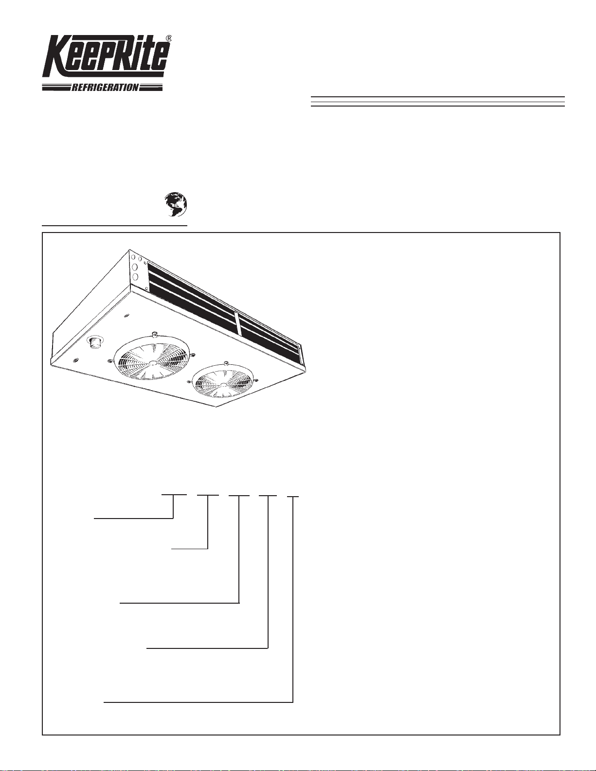
KTW Two-Way
Unit Coolers
High, Medium and Low Temperature
Applications -10°F (-23.3 °C) Room
and above
Air or Electric Defrost Models
Electrical Power:115/1/60,
208-230/1/60, 200-220/1/50
• Low height compact size maximizes useable
storage space
• Dual refrigeration coils and two-way air
distribution reduces air velocities to minimize
product dehydration.
NOMENCLATURE
KTW 009 AD - S1 A
KeepRite
Two-Way Unit Cooler
o
Nominal Capacity @ 10
9 = 900 Btuh
Air Defrost (AD) rated at 20 °F Evap. T emp.
Electric Defrost (ED) rated at -20°F Evap. T emp.
Type of Defrost
AD = Air Defrost
ED = Electric Defrost
Electrical Designation
S1 = 115/1/60
S2 = 208-230/1/60
S6 = 200-220/1/50
F TD
• Air enters through fan and discharges two ways
out of each coil side.
• NEW rugged heavy duty motor mount reduces
vibration and noise.
• Electric defrost models include factory installed
defrost termination and fan delay thermostat.
• NSF approved “flush to ceiling mount”
• Refrigerants R134a, R22 and R404A.
CONTENTS PAGE
General Specifications.......................
Wiring Diagrams..................................
Dimensional Data................................
TXV / Nozzle Selections.......................
Installation Instructions......................
Service Parts List................................
Service Log.........................................
2, 3
4 - 6
7, 8
9
10, 11
Back
Back
Unit Series
A = First Generation
Page 2
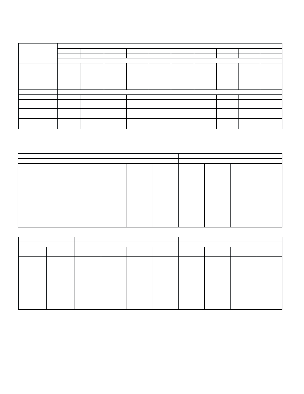
60Hz Capacity Data - BTUH
60Hz SPECIFICATIONS
pmeT.pavE
)C°(F°
)9.3-/7.6-(52+/02+
)2.21-(01+
)8.71-(0
)3.32-(01-
)9.82-(02-
)9.3-/7.6-(52+/02+503109810942540305730054057600090053105271
MFC03108173207204404482970824210061
BL.girfeR
GK*egrahC
.BLtinU
GKthgieW
078
358
728
297
047
4.0
2.0
3.5
* Coil at 30% full (liquid)
60Hz Electrical Data
zH06-1-v511
rebmuNledoMWTK)s(rotoMnaFsretaeHtsorfeD
tsorfeDriAcirtcelE
A1S-DA900
A1S-DA310
A1S-DA710
A1S-DA020
A1S-DA520
A1S-DA030
A1S-DA540
A1S-DA060
A1S-DA090
A1S-DA511
A1S-DE800
A1S-DE110
A1S-DE510
A1S-DE810
A1S-DE220
A1S-DE620
A1S-DE930
A1S-DE150
A1S-DE770
A1S-DE890
)tsorfeDcirtcelE(DE)tsorfeDriA(DArebmuNledoMWTK
DA900DA310DA710DA020DA520DA030DA540DA060DA090DA511
DE800DE110DE510DE810DE220DE620DE930DE150DE770DE890
0621
5321
7911
7411
1701
5.0
6.11
2.0
6.21
7.5
ytitnauQ
)aePH52/1(
1
1
1
1
1
1
2
2
3
4
0661
7261
7751
1151
1141
7.0
3.0
7.31
2.6
latoT
ALF
2.1
2.1
2.1
2.1
2.1
2.1
4.2
4.2
6.3
8.4
0302
9891
9291
7481
6271
8.0
4.0
7.41
7.6
ACM
)spmA(
5.1
5.1
5.1
5.1
5.1
5.1
7.2
7.2
9.3
1.5
0052
0542
5732
5722
5212
9.0
4.0
9.81
6.8
sledoMtsorfeDcirtcelEdnatsorfeDriA sledoMtsorfeDcirtcelE
POM
)spmA(
51
51
51
51
51
51
51
51
51
51
DT)C°6.5(F°01@yticapaC
0003
0492
0582
0372
0552
2.1
5.0
0.02
1.9
0054
0144
5724
5904
5283
DT)C°4.8(F°51@yticapaC
4.1
6.0
8.73
2.71
latoT
sttaW
602
035
035
035
057
057
0011
0451
0722
0172
0006
0885
0075
0645
0015
3.2
0.1
9.93
1.81
latoT
spmA
8.1
6.4
6.4
6.4
5.6
5.6
6.9
4.31
7.91
6.32
0009
0288
0558
0918
0567
4.3
5.1
9.95
2.72
ACM
)spmA(
2.2
8.5
8.5
8.5
2.8
2.8
0.21
8.61
6.42
5.92
00511
07211
52901
56401
5779
0.4
8.1
8.97
3.63
POM
)spmA(
51
51
51
51
51
51
51
02
52
03
zH06-1-v032/802
rebmuNledoMWTK)s(rotoMnaFsretaeHtsorfeD
tsorfeDriAcirtcelE
A2S-DA900
A2S-DA310
A2S-DA710
A2S-DA020
A2S-DA520
A2S-DA030
A2S-DA540
A2S-DA060
A2S-DA090
A2S-DA511
A2S-DE800
A2S-DE110
A2S-DE510
A2S-DE810
A2S-DE220
A2S-DE620
A2S-DE930
A2S-DE150
A2S-DE770
A2S-DE890
MCA = Minimum Circuit Ampacity
MOP = Maximum Overcurrent Protection
sledoMtsorfeDcirtcelEdnatsorfeDriA sledoMtsorfeDcirtcelE
ytitnauQ
)aePH52/1(
1
1
1
1
1
1
2
2
3
4
latoT
ALF
7.0
7.0
7.0
7.0
7.0
7.0
4.1
4.1
1.2
8.2
ACM
)spmA(
9.0
9.0
9.0
9.0
9.0
9.0
6.1
6.1
3.2
0.3
POM
)spmA(
51
51
51
51
51
51
51
51
51
51
latoT
sttaW
602
035
035
035
057
057
0011
0451
0722
0172
latoT
spmA
9.0
3.2
3.2
3.2
3.3
3.3
8.4
7.6
9.9
8.11
ACM
)spmA(
1.1
9.2
9.2
9.2
1.4
1.4
0.6
4.8
4.21
8.41
POM
)spmA(
51
51
51
51
51
51
51
51
51
51
- 2-
Page 3
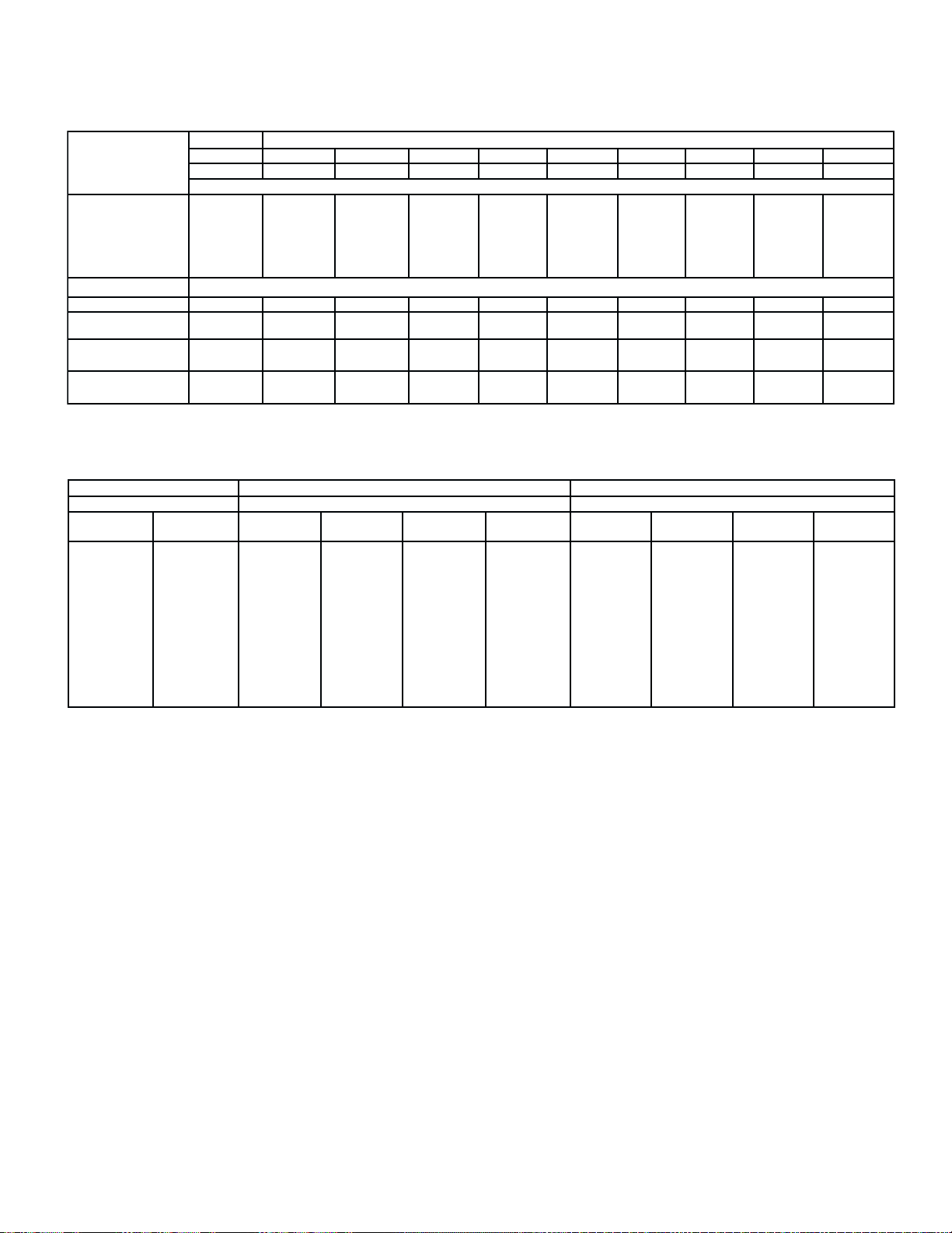
50Hz Capacity Data - BTUH
50Hz SPECIFICATIONS
pmeT.pavE
)C°(F°
)9.3-/7.6-(52+/02+
)2.21-(01+
)8.71-(0
)3.32-(01-
)9.82-(02-
)9.3-/7.6-(52+/02+102193711922108205430414012608280242107851
MFC80194179142256356307707613018231
BL.girfeR
GK*egrahC
.BLtinU
GKthgieW
DA900DA310DA710DA020DA520DA030DA540DA060DA090DA511
DE800DE110DE510DE810DE220DE620DE930DE150DE770DE890
008
487
067
827
086
4.0
2.0
6.11
3.5
50Hz Electrical Data
zH05-1-v022/002
rebmuNledoMWTK)s(rotoMnaFsretaeHtsorfeD
tsorfedriAcirtcelE
A6S-DA900
A6S-DA310
A6S-DA710
A6S-DA020
A6S-DA520
A6S-DA030
A6S-DA540
A6S-DA060
A6S-DA090
A6S-DA511
MCA = Minimum Circuit Ampacity
MOP = Maximum Overcurrent Protection
A6S-DE800
A6S-DE110
A6S-DE510
A6S-DE810
A6S-DE220
A6S-DE620
A6S-DE930
A6S-DE150
A6S-DE770
A6S-DE890
)tsorfeDcirtcelE(DE)tsorfeDriA(DArebmuNledoMWTK
DT)C°6.5(F°01@yticapaC
9511
6311
1011
5501
589
5.0
2.0
6.21
7.5
ytitnauQ
)aePH52/1(
1
1
1
1
1
1
2
2
3
4
7251
7941
1541
0931
8921
7.0
3.0
7.31
2.6
latoT
ALF
7.0
7.0
7.0
7.0
7.0
7.0
4.1
4.1
1.2
8.2
8681
0381
4771
0071
7851
8.0
4.0
7.41
7.6
ACM
)spmA(
9.0
9.0
9.0
9.0
9.0
9.0
6.1
6.1
3.2
0.3
0032
4522
5812
3902
5591
9.0
4.0
9.81
6.8
sledoMtsorfeDcirtcelEdnatsorfeDriA sledoMtsorfeDcirtcelE
POM
51
51
51
51
51
51
51
51
51
51
0672
5072
2262
2152
6432
2.1
5.0
0.02
1.9
)spmA(
0414
7504
3393
7673
9153
DT)C°4.8(F°51@yticapaC
4.1
6.0
8.73
2.71
latoT
sttaW
881
584
584
584
686
686
7001
9041
7702
0842
0255
0145
4425
3205
2964
3.2
0.1
9.93
1.81
latoT
spmA
9.0
2.2
2.2
2.2
1.3
1.3
6.4
4.6
4.9
3.11
0828
4118
6687
5357
8307
4.3
5.1
9.95
2.72
ACM
)spmA(
1.1
8.2
8.2
8.2
9.3
9.3
7.5
0.8
8.11
1.41
08501
86301
15001
8269
3998
0.4
8.1
8.97
3.63
POM
)spmA(
51
51
51
51
51
51
51
51
51
51
- 3 -
Page 4
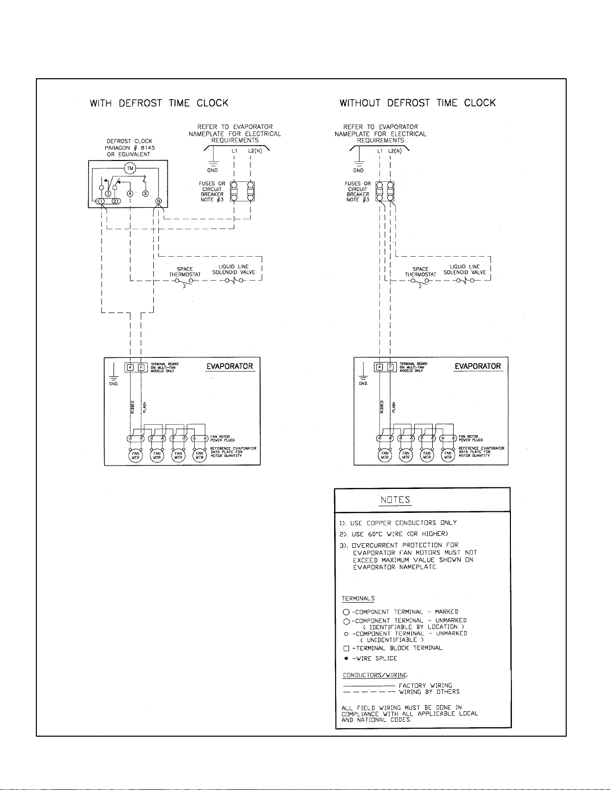
WIRING DIAGRAMS
AIR DEFROST - All Voltages
- 4 -
Page 5

WIRING DIAGRAMS
ELECTRIC DEFROST - 115V
- 5 -
Page 6

WIRING DIAGRAMS
ELECTRIC DEFROST - 230V
- 6 -
Page 7

DIMENSIONAL DATA
SINGLE FAN MODELS
3”
(76 mm)
1-3/8”
(35 mm)
B
AIR
OUT
Defrost Control
E
CONNECTION END VIEW SIDE VIEW
AIR IN
A
7/8 (22 mm) dia.
knockouts
2 connection end
AIR
OUT
1/2 (12 mm) dia. O.D.
9/16 (14 mm) dia.
knockouts
2 each side
7/8 (22 mm) dia.
knockouts
2 each side
aluminum drain
C
BOTTOM VIEW
Splice box.
Electric defrost models
NOTE: Dimensional views shown
with electric defrost heaters
splice box and defrost control
mounted.
4 Mounting holes
7/32 (6 mm) dia.
* TXV conn.
1/2” flare
Suction
3/8” O.D.
D
9/16”
(14 mm)
DE/DA:LEDOM
800/900WTK
110/310WTK
510/710WTK
810/020WTK
220/520WTK
620/030WTK
* TXV Connection on KTW 026 ED only is 1/2” O.D.S.
ABCDE
)MM(SEHCNI-ATADLANOISNEMID
)974(8/781)411(2/14)953(8/141)154(4/371)842(4/39
)974(8/781)411(2/14)953(8/141)154(4/371)842(4/39
)974(8/781)041(2/15)953(8/141)154(4/371)842(4/39
)974(8/781)041(2/15)953(8/141)154(4/371)842(4/39
)555(8/712)041(2/15)684(8/191)725(4/302)573(4/341
)555(8/712)041(2/15)684(8/191)725(4/302)573(4/341
- 7 -
Page 8

DIMENSIONAL DATA
MULTIPLE FAN MODELS
DE/DA:LEDOMsnaFfo.oN
930/540WTK
150/060WTK
770/090WTK
890/511WTK
)MM(SEHCNI-ATADLANOISNEMID
.nnoCnoitcuSCDEF
2)31(.DO"2/1)6801(4/324)302("8@seloh4)591(61/117)872(61/5101
2)61(.DO"8/5)6801(4/324)302("8@seloh4)591(61/117)872(61/5101
3)61(.DO"8/5)1151(2/195)302("8@seloh6)302(8)192(61/711
4)22(.DO"8/7)9571(4/196)302("8@seloh8)711(8/54)912(8/58
- 8 -
Page 9

TXV / NOZZLE SELECTIONS - 60Hz
All models require the use of a TXV (thermostatic expansion valve). These should be mounted within the cabinet at the flare
nut connection or distributor stub (all 026 ED and higher models ). An internally equalized TXV can be used on any of the
single fan AD models and 022 ED and smaller electric defrost models. All other models must use an externally equalized
TXV. (a 1/4 “ OD equalizing tube is provided). All models using a distributor require a nozzle. Air Defrost models have the
nozzle already FACTORY installed. Electric defrost models 026ED and larger have TWO distributor nozzles SHIPPED
LOOSE and the correct selection must be made and installed prior to mounting the TXV. Refer to the following charts for
nozzle / TXV selections.
NOZZLE SELECTIONS
Air Defrost Nozzles (already factory installed)
For all applications and refrigerants
ledoMelzzoN
DA5402/1-L
DA0604/3-L
DA0901-L
DA5112/11-L
SPORLAN TXV SELECTIONS
Air Defrost (35 °F and up Room Temperatures)
ledoM
DA900078
DA3100621
DA7100661
DA0200302
DA5200052
DA0300003
DA5400054
DA0600006
DA0900009
DA51100511
Note: Based on 100 °F Liquid Temperature
hutBa431R/21R22R205R/A404RhutBa431R/21R22R205R/A404R
DTF°01 DTF°51
C8/1-JGC5/1-VGC8/1-SG
C8/1-JGC5/1-VGC8/1-SG
C8/1-JGC5/1-VGC8/1-SG
C8/1-JGC5/1-VGC8/1-SG
C4/1-JGC5/1-VGC4/1-SG
C4/1-JGC5/1-VGC4/1-SG
C2/1-EJGEC2/1-EVGEC2/1-ESGE
C2/1-EJGEC4/3-EVGEC2/1-ESGE
C1-EJGEC1-EVGEC1-ESGE
C1-EJGEC1-EVGEC1-ESGE
R22 Electric Defrost (34 °F and below Room Temperatures) 10 °F TD
/ledoMDE800DE110DE510DE810DE220
.pmeTpavEhutB#evlaVhutB#evlaVhutB#evlaVhutB#evlaVhutB#evlaV
F°52+/02+078
F°01+358
F°0728
F°01-297
F°02-047
/ledoMDE620DE930DE150DE770DE890
.pmeTpavEhutB#evlaVhutB#evlaVhutB#evlaVhutB#evlaVhutB#evlaV
F°52+/02+0003
F°01+0492
F°00582
F°01-0372
F°02-0552
Note: Based on 95 °F Liquid Temperature for -20 °F / -10 °F Evap. Temps. and 100 °F Liquid for 0 to +25 °F Evap. Temps.
CV5/1-VG
CV5/1-VG
CV5/1-VG
ZV5/1-VG
ZV5/1-VG
CV5/1-EVGE
CV5/1-EVGE
CV3/1-EVGE
ZV3/1-EVGE
ZV3/1-EVGE
0621
5321
7911
7411
1701
0054
0144
5724
5904
5283
CV5/1-VG
CV5/1-VG
CV5/1-VG
ZV5/1-VG
ZV5/1-VG
CV3/1-EVGE
CV3/1-EVGE
CV3/1-EVGE
ZV2/1-EVGE
ZV2/1-EVGE
R404A Electric Defrost (34 °F and below Room Temperatures) 10 °F TD
/ledoMDE800DE110DE510DE810DE220
.pmeTpavEhutB#evlaVhutB#evlaVhutB#evlaVhutB#evlaVhutB#evlaV
F°52+/02+078
F°01+358
F°0728
F°01-297
F°02-047
/ledoMDE620DE930DE150DE770DE890
.pmeTpavEhutB#evlaVhutB#evlaVhutB#evlaVhutB#evlaVhutB#evlaV
F°52+/02+0003
F°01+0492
F°00582
F°01-0372
F°02-0552
Note: Based on 95 °F Liquid Temperature for -20 °F / -10 °F Evap. Temps. and 100 °F Liquid for 0 to +25 °F Evap. Temps.
CS8/1-SG
CS8/1-SG
CS8/1-SG
ZS8/1-SG
ZS8/1-SG
CS6/1-ESGE
CS6/1-ESGE
CS6/1-ESGE
ZS6/1-ESGE
ZS6/1-ESGE
0621
5321
7911
7411
1701
0054
0144
5724
5904
5283
CS8/1-SG
CS8/1-SG
CS8/1-SG
ZS8/1-SG
ZS8/1-SG
CS4/1-ESGE
CS4/1-ESGE
CS4/1-ESGE
ZS4/1-ESGE
ZS2/1-ESGE
Electric Defrost Nozzles (for field installation)
For -20°F to +25 °F Evap. Temps., 8-12°F TD
ledoM
DE620
DE930
DE150
DE770
DE890
* Use L-1/16 if lower than 9°F T.D.
5031
0981
0942
5403
0573
0054
0576
0009
00531
05271
0661
7261
7751
1151
1141
0006
0885
0075
0645
0015
0661
7261
7751
1151
1141
0006
0885
0075
0645
0015
CV5/1-VG
CV5/1-VG
CV5/1-VG
ZV5/1-VG
ZV5/1-VG
CV2/1-EVGE
CV2/1-EVGE
CV2/1-EVGE
ZV4/3-EVGE
ZV4/3-EVGE
CS8/1-SG
CS8/1-SG
CS8/1-SG
ZS8/1-SG
ZS8/1-SG
CS2/1-ESGE
CS2/1-ESGE
CS2/1-ESGE
ZS2/1-ESGE
ZS2/1-ESGE
22RA404R
*4/1-L
3/1-L
2/1-L
4/3-L
1-L
0302
9891
9291
7481
6271
0009
0288
0558
0918
0567
0302
9891
9291
7481
6271
0009
0288
0558
0918
0567
elzzoN
C8/1-JGC5/1-VGC8/1-SG
C4/1-JGC5/1-VGC8/1-SG
C4/1-JGC5/1-VGC8/1-SG
C4/1-JGC5/1-VGC4/1-SG
C4/1-JGC3/1-VGC4/1-SG
C2/1-JGC3/1-VGC4/1-SG
2/1-EJGEC4/3-EVGEC2/1-ESGE
C1-EJGEC1-EVGEC1-ESGE
C1-EJGEC2/11-EVGEC1-ESGE
C2/11-EJGEC2/11-EVGEC2/11-ESGE
CV5/1-VG
CV5/1-VG
CV5/1-VG
ZV5/1-VG
ZV5/1-VG
CV4/3-EVGE
CV4/3-EVGE
CV4/3-EVGE
ZV4/3-EVGE
ZV4/3-EVGE
CS8/1-SG
CS8/1-SG
CS8/1-SG
ZS8/1-SG
ZS8/1-SG
CS2/1-ESGE
CS2/1-ESGE
CS2/1-ESGE
ZS2/1-ESGE
ZS1-ESGE
- 9 -
3/1-L
2/1-L
4/3-L
1-L
2/11-L
0052
0542
5732
5722
5212
00511
07211
52901
56401
5779
0052
0542
5732
5722
5212
00511
07211
52901
56401
5779
CV5/1-VG
CV5/1-VG
CV5/1-VG
ZV5/1-VG
ZV5/1-VG
ZV1-EVGE
ZV1-EVGE
ZV1-EVGE
CS8/1-SG
CS8/1-SG
CS8/1-SG
ZS8/1-SG
ZS8/1-SG
CS1-ESGE
CS1-ESGE
CS1-ESGE
ZS1-ESGE
ZS1-ESGE
CV4/3-EVGE
CV4/3-EVGE
Page 10

INSTALLATION INSTRUCTIONS
INSPECTION
Careful inspection of all parts when received for loss
or damage in transit is very important - Remember,
you, the consignee, must make any claim necessary
against the transportation company. Shipping
damage or missing parts, when discovered at the
outset, will prevent later unnecessary and costly
delays.
Electrical characteristics should also be checked at
this time to ensure that they are as ordered.
APPLICATION
Two-Way Unit Coolers are designed for use in
coolers and freezers such as reach in boxes, display
cases, back bars, walk-in rooms and any other
cooler applications where a low velocity, uniform air
flow is required. The compact and low height unit
provides maximum useable product storage space.
o
At room temperatures above 34
evaporating temperatures no lower than 27
o
C) the air flowing through the coil will accomplish
F (1.1 oC) and
o
F (-2.8
the defrost (Air Defrost).
o
At room temperatures 34
F and below ( to -10 oF)
positive defrosting is required ( Electric defrost) .
These will require the use of :
1. Time Clock (to initiate and terminate the defrost
cycle ),
2. Defrost termination thermostat (to prevent
unnecessary prolonged heating and steaming of the
coil once all the frost and ice has melted). And if a
freezer,
3. Fan delay thermostat (to prevent evaporator fans
starting up right away and blowing water on to the
fan blades, guards and floor).
This evaporator coil must not be exposed to any
abnormal environments (acidic or caustic) that can
result in coil corrosion and leaks. Consult factory for
optional baked on phenolic protective coatings.
These unit coolers are for use primarily on R134a,
R22 and R404A refrigerants and their approved
alternatives / replacements.
INSTALLATION
The installation and start up of Unit Coolers should
only be performed by qualified refrigeration
mechanics. This equipment should be installed in
accordance with all applicable codes, ordinances,
and local by-laws.
LOCATION
The Unit Cooler is designed to be mounted to the
ceiling of the box or cabinet. Refrigeration piping and
electrical connections are routed to the rear sides
(through the knock-outs). The unit must be mounted
to a level ceiling to ensure complete drainage from
the condensate pan to the drain fitting. Refer to the
dimensional drawings for the drain fitting and
mounting location details.
On freezer applications it is important that warm,
humid infiltrated air is not drawn directly towards
the unit cooler. Keeping the unit cooler away from
the door, using strip curtains, and using door
switches to lock out and de-energize the liquid solenoid valve are all effective methods to minimize
any unnecessary frost build -up of the fan guard.
(Air enters the fan and discharges out each side of
the coil ).
TXV (thermostatic expansion valve)
SELECTION
For normal operating conditions refer to the TXV
selection chart on P. 9. When selecting valves
ensure they are sized to meet the capacity at the
actual evaporating temperature, liquid temperature
and operating TD of the system . All these conditions
can greatly affect the size and selection. Consult
the factory or valve manufacturer for assistance. All
models that use a distributor (larger models) must
use a nozzle. Smaller models do not have
distributors or nozzles.
Electric defrost models 026ED and higher require
a nozzle to be selected and field installed before
mounting the TXV. Refer to P.9 for details. Air defrost
models 045AD and higher already have the nozzle
factory installed.
- 10 -
Page 11

INSTALLATION INSTRUCTIONS
The TXV superheat setting should NOT be initially
adjusted . After the room has reached or is close to
the required operating temperature the TXV superheat should then be checked and only adjusted if
necessary. Refer to Section on SYSTEM CHECK.
To avoid overheating the valve or distributor
wrap a wet cloth around the valve diaphragm
and body.
MOUNTING
Mounting brackets with 7/32 - 5/16” diameter holes
are provided for flush mounting to the ceiling. For
details refer to the dimensional data on P.7 and 8.
Ensure the evaporator is located correctly with the
air flowing in the two desired directions.
Avoid discharging the air directly on to glass doors
or door openings.
After mounting the coil check the slope of the drain
pan with a level. If the ceiling is not level the drain
pan slope may not be correct which can result in
defrosting (ice-up) problems.
DRAIN LINE
The drain line should be run from the drain
connection, sloping at least 4" vertical drop
for every foot of horizontal distance . A trap outside
the room will allow proper draining throughout the
line. Connection should be made to proper drainage
facilities that comply with local codes and
regulations.
In freezers, to prevent drain line freeze up problems,
the line must be heated and insulated. A heat input
o
of 20 W per foot in a 0
o
a -20
F room is usually satisfactory. Once the line
F room and 30 W per foot in
has been completed , double check the slope in the
drain pan to ensure proper drainage (prevention of
ice build-up on pan).
PIPING
Refrigerant line sizes are important and are not
necessarily the same size as the connections at the
condensing unit or evaporator. If in doubt refer to a
recognized source. (Manufacturer’s Engineering
Manual, Ashrae Manuals, etc.)
WIRING
Wire system in accordance with local codes and
regulations. A 36" cord is provided for single fan air
defrost models (AD) .Multiple fans have a junction
terminal box for conduit connections.
See electrical data and wiring diagrams on P. 2 - 6.
When Fan delay thermostats are installed the fans
may not start up until the coil temperature
o
reaches approximately 26
F . On initial start up it
may be necessary to bypass (jumper) this control
temporarily until the coil is cold enough.
SYSTEM CHECK
Before Start Up:
1. Ensure wiring is in accordance with codes.
2. Refrigerant lines are properly sized and routed.
3. Thorough leak check, evacuation and
dehydration has been performed.
4. Drain line has been checked for free flow.
After Start Up:
1. Fan has been checked for correct air flow and no
obstructions.
2. Expansion valve superheat has been checked for
proper operation. (Superheat of the coil should
o
be around 5 to 6
MAINTENANCE
The unit should be periodically inspected for any dirt
or build up on the fin surface and cleaned if
necessary with a soft whisk or brush.
The fan motor is permanently lubricated and should
not require service.
F for a 10 oF TD.)
-11 -
Page 12

SERVICE P ARTS LIST
06/29/07
REBMUNLEDOMROTOMNAF
RIACIRTCELE06/1/51106/1/032-802)ylnosledomDE(
DA90
0WTKDE800WTK
DA310WTKDE110WTK
DA710WTKDE510WTK
DA020WTKDE810WT
DA520WTKDE220WTK
DA030WTKDE620WTK
DA540WTKDE930WTK
DA060WTKDE150WTK
DA090WTKDE770WTK
DA511WTKDE890WTK
DcirtcelE 0600701
* All heaters are rated at 115V - either wired in series (for 230V) or parallel (for 115V)
K
29596013959601100-07834013923401100-8640701100-8683401
29596013959601200-07834013923
29596013959601300-07834013923401100-1689601100-8683401
29596013959601400-07834013923401100-1689601100-8683401
29596013959601500-07834014923401200-1689
29596013959601500-07834014923401200-1689601100-9683401
2959601395
29596013959601500-07834014923401300-1689601100-0100
29596013959601600-07834014923401400-1689601100-1100701
29596013959601600-078
-draoBlanimreT)pudna540(tsorfeDriA 5288401
-draoBlanimreT)pudna930(tsorfe
9601500-07834014923401200-8640701100-0100701
-lortnoCnoitanimreTtsorfeD/yaleDnaFtsorfeDcirtcelE 5273401
SERVICE LOG
ETADSTNEMMOC
EDALBNAFDRAUGNAF
401100-1689601100-8683401
601100-9683401
34014923401500-1689601100-2100701
*SRETAEHTSORFED
NAPNIARD
701
PROJECT INFORMA TION
metsyS
rebmuNledoM pU-tratSfoetaD
rebmuNlaireS rotcartnoCecivreS
tnaregirfeRenohP
ylppuSlacirtcelExaF
NA TIONAL REFRIGERA TION &
AIR CONDITIONING CANADA CORP.
CANADA
159 ROY BL VD., BRANTFORD, ONT ARIO, CANADA N3R 7K1
PHONE: 1-800-463-9517 (519)751-0444 FAX (519)753-1140
Due to National Refrigeration’s policy of continuous product improvement, we reserve the right to make changes without notice.
USA
985 WHEELER WA Y, LANGHORNE, P A. 19047 USA
PHONE:1-888-KEEPUS1 OR 1-888-533-7871
 Loading...