

Page 1
PRODUCT DATA &
08/14/12
INSTALLATION
Bulletin K30-KTM-PDI-3
1087840
KTM Two-Way
Medium Prole
Unit Coolers
High, Medium and Low
Temperature
Applications -10°F (-23.3 °C) or
Above Box Temperature
Latest product updates and further information
at www.keepriterefrigeration.com
Air, Electric or Hot Gas
Defrost (Reverse Cycle)
CONTENTS
Nomenclature...................................................................................................................... 2
Features............................................................................................................................... 2
Page
Capacity Data (Imperial and Metric)................................................................................. 3
Electrical Data..................................................................................................................... 4 - 5
Wiring Diagrams.................................................................................................................. 6 - 9
Mechanical Data................................................................................................................. 10
Dimensional Data............................................................................................................... 11
Installation Clearances....................................................................................................... 12
TXV Selection..................................................................................................................... 13 - 15
Installation Instructions........................................................................................................ 16 - 17
Generic Service Parts List................................................................................................. 18
Warranty............................................................................................................................... 19
Project Information.............................................................................................................. 19
“As Built” Service Parts List............................................................................................... BACK
Page 2

Model Name
K30-KTM-PDI-3
- 2 -
08/14/12
K = KeepRite
NOMENCLATURE
K TM 2 9 5 M A - S1 A
Design Version
Product Name
TM = Two Way Medium Prole Unit Cooler
X 100 = Nominal Capacity
(10°F TD, 60Hz), Btu/H
Evap Temp Range
M = Medium Temp (10 - 45°F), 6 FPI.
L = Low Temp (-20 - 0°F), 6 FPI.
STANDARD FEATURES
• Heavy gauge textured aluminum cabinet
construction resists scratches/corrosion and
minimizes weight for shipment, installation and
service.
• Capacity up to 29,500 BTUH nominal.
• Dual refrigeration coils with two-way air
distribution reduces air velocities to minimize
product dehydration.
• Air enters through fan and discharges two
ways out of each coil side.
• Low height compact size useable storage
space.
Unit Electrical Designaton.
S1 = 115/1/60 (air defrost models only)
S2 = 208-230/1/60
S6 = 200-220/1/50
Defrost Type.
A = Air Defrost
E = Electric Defrost
G = Reverse Cycle w/ Electric Heater Pan
• Internally enhanced tube.
• Attractive and durable high - density
polyethylene fan guards.
• Standard PSC motors
• Hinged drain pan provides convenient access
for cleaning.
• Terminal board allows for easy electrical
connections.
• Reduced operating charge with 3/8” OD tubing
• Refrigerants R22, R404A, R507, R407C.
• Factory mounted solenoid valve, TXV and
Thermostat on air and electric defrost models.
• Fin material and special coatings.
OPTIONAL FEATURES
• Other options available - consult factory.
• ECM motors
Page 3
CAPACITY DATA
K30-KTM-PDI-3
- 3 -
08/14/12
KTM
R404A
60Hz
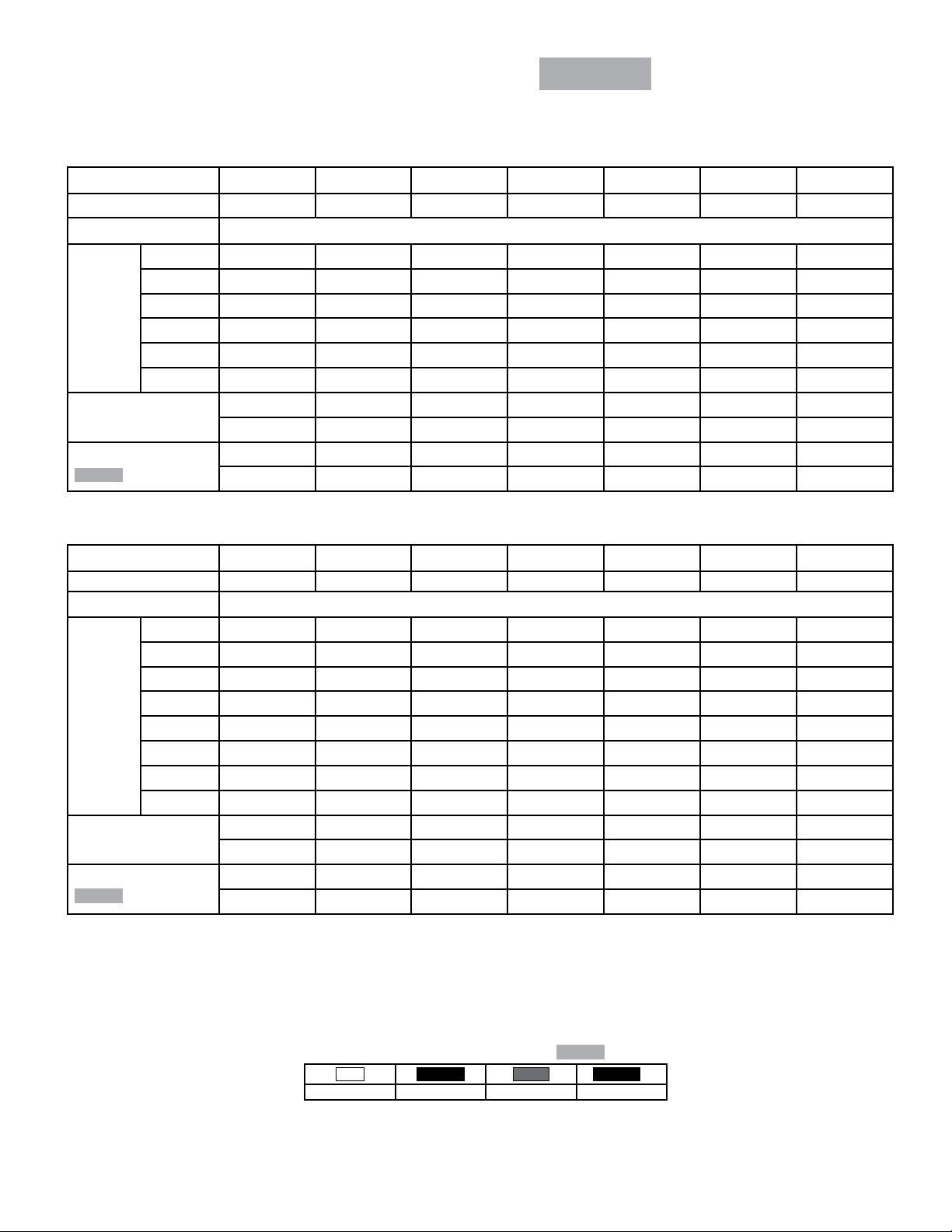
MEDIUM TEMPERATURE MODELS - CAPACITY
KTM115M KTM139M KTM172M KTM208M KTM236M KTM260M KTM295M
Number of Fans 2 2 3 3 4 4 5
Capacity BTUH (watts)
+ 20/25 11500 13900 17200 20800 23600 26000 29500
(-3.9/-6.7) (3370) (4074) (5041) (6096) (6916) (7620) (8646)
Evap
Temp
°F (°C)
Air Flow
CFM (L/s)
Refrigerant Charge*
R404A
15 11330 13690 16940 20490 23250 25610 29060
(-9.4) (3320) (4012) (4965) (6005) (6814) (7506) (8517)
10 11270 13620 16860 20380 23130 25480 28910
(-12.2) (3303) (3992) (4941) (5973) (6779) (7467) (8473)
2020 1900 3030 2850 3700 3780 4630
(953) (897) (1430) (1345) (1746) (1760) (2185)
2.1 2.8 3.1 4.2 4.2 5.2 5.2
Lbs (Kg)
(1.0) (1.3) (1.4) (1.9) (1.9) (2.4) (2.4)
LOW TEMPERATURE MODELS - CAPACITY
KTM105L KTM124L KTM153L KTM188L KTM210L KTM235L KTM265L
Number of Fans 2 2 3 3 4 4 5
Capacity BTUH (watts)
0 11240 13270 16370 20120 22470 25150 28360
(-17.8) (3294) (3889) (4798) (5897) (6585) (7371) (8311)
-10 10920 12900 15910 19550 21840 24440 27560
Evap
Temp
°F (°C)
Air Flow
CFM (L/s)
Refrigerant Charge*
R404A
*R404A @ +25 °F S.S.T. with coil 30% full of liquid
Capacities rated using R404A with 10° F (5.6°C) TD & 100°F (38°C) liquid temperature.
Capacities at other TD within a range of 8 to 15°F (4.4 to 8.3°C) are directly proportional to TD, or use formula”
CAPACITY = (RATED CAPACITY / 10) x TD
(-23.3) (3200) (3781) (4663) (5730) (6401) (7163) (8077)
-15 10710 12650 15610 19180 21420 23970 27030
(-26.1) (3139) (3707) (4575) (5621) (6278) (7025) (7922)
-20 10500 12400 15300 18800 21000 23500 26500
(-28.9) (3077) (3634) (4484) (5510) (6154) (6887) (7766)
2020 1900 3030 2850 3700 3780 4630
(953) (897) (1430) (1345) (1746) (1760) (2185)
2.1 2.8 3.1 4.2 4.2 5.2 5.2
Lbs (Kg)
(1.0) (1.3) (1.4) (1.9) (1.9) (2.4) (2.4)
‡ When using R407C, the factor above is to be used when matching to condensing units with Dew Point ratings. This factor will ensure that proper
system balancing will occur to compensate for glide to t the application. If the system is sized correctly, one may expect a slight increase in system
capacity, along with slightly higher saturated suction temperatures.
Correction Factors for Other Refrigerants Use
R22
0.95 0.90 1.00 0.90
R134a
R507
R404A
Values Multiplied By:
R407C
‡
Page 4
KTM
K30-KTM-PDI-3
- 4 -
08/14/12
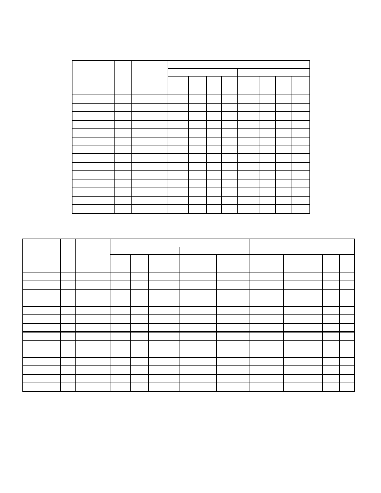
ELECTRICAL DATA
AIR DEFROST
FAN MOTOR(S)
MODEL
KTM115MA-S1 2 115/1/60 2.2 2.5 200 15 3 3.4 104 15
KTM139MA-S1 2 115/1/60 2.2 2.5 200 15 3 3.4 104 15
KTM172MA-S1 3 115/1/60 3.3 3.6 300 15 4.5 4.9 156 15
KTM208MA-S1 3 115/1/60 3.3 3.6 300 15 4.5 4.9 156 15
KTM236MA-S1 4 115/1/60 4.4 4.7 400 15 6 6.4 208 15
KTM260MA-S1 4 115/1/60 4.4 4.7 400 15 6 6.4 208 15
KTM295MA-S1 5 115/1/60 5.5 5.8 500 15 7.5 7.9 260 15
KTM115MA-S2 2 208-230/1/60 1.0 1.1 200 15 2.0 2.3 104 15
KTM139MA-S2 2 208-230/1/60 1.0 1.1 200 15 2.0 2.3 104 15
KTM172MA-S2 3 208-230/1/60 1.5 1.6 300 15 3.0 3.3 156 15
KTM208MA-S2 3 208-230/1/60 1.5 1.6 300 15 3.0 3.3 156 15
KTM236MA-S2 4 208-230/1/60 2.0 2.1 400 15 4.0 4.3 208 15
KTM260MA-S2 4 208-230/1/60 2.0 2.1 400 15 4.0 4.3 208 15
KTM295MA-S2 5 208-230/1/60 2.5 2.6 500 15 5.0 5.3 260 15
No.
of
FANS
POWER
SUPPLY
PSC-Standard ECM-Optional
TOTAL
MOTOR
FLA
M.C.A. Watts M.O.P
TOTAL
MOTOR
FLA
M.C.A. Watts M.O.P
60Hz
ELECTRIC DEFROST
FAN MOTOR(S)
MODEL
KTM115ME-S1 2 208-230/1/60 1.0 1.1 200 15 2.0 2.3 104 15 208-230/1/60 2600 11.3 14.1 15
KTM139ME-S1 2 208-230/1/60 1.0 1.1 200 15 2.0 2.3 104 15 208-230/1/60 2600 11.3 14.1 15
KTM172ME-S1 3 208-230/1/60 1.5 1.6 300 15 3.0 3.3 156 15 208-230/1/60 3720 16.2 20.3 25
KTM208ME-S1 3 208-230/1/60 1.5 1.6 300 15 3.0 3.3 156 15 208-230/1/60 3720 16.2 20.3 25
KTM236ME-S1 4 208-230/1/60 2.0 2.1 400 15 4.0 4.3 208 15 208-230/1/60 3720 16.2 20.3 25
KTM260ME-S1 4 208-230/1/60 2.0 2.1 400 15 4.0 4.3 208 15 208-230/1/60 4560 19.8 24.8 25
KTM295ME-S1 5 208-230/1/60 2.5 2.6 500 15 5.0 5.3 260 15 208-230/1/60 4560 19.8 24.8 25
KTM105LE-S2 2 208-230/1/60 1.0 1.1 200 15 2.0 2.3 104 15 208-230/1/60 2600 11.3 14.1 15
KTM124LE-S2 2 208-230/1/60 1.0 1.1 200 15 2.0 2.3 104 15 208-230/1/60 2600 11.3 14.1 15
KTM153LE-S2 3 208-230/1/60 1.5 1.6 300 15 3.0 3.3 156 15 208-230/1/60 3720 16.2 20.3 25
KTM188LE-S2 3 208-230/1/60 1.5 1.6 300 15 3.0 3.3 156 15 208-230/1/60 3720 16.2 20.3 25
KTM210LE-S2 4 208-230/1/60 2.0 2.1 400 15 4.0 4.3 208 15 208-230/1/60 3720 16.2 20.3 25
KTM235LE-S2 4 208-230/1/60 2.0 2.1 400 15 4.0 4.3 208 15 208-230/1/60 4560 19.8 24.8 25
KTM265LE-S2 5 208-230/1/60 2.5 2.6 500 15 5.0 5.3 260 15 208-230/1/60 4560 19.8 24.8 25
No.
FANS
of
POWER
SUPPLY
PSC-Standard ECM-Optional
TOTAL
MOTOR
FLA
M.C.A. Watts M.O.P
TOTAL
MOTOR
FLA
M.C.A. Watts M.O.P
POWER
SUPPLY
DEFROST HEATERS
TOTAL
WATTS
TOTAL
MOTOR
FLA
M.C.A. M.O.P
Page 5
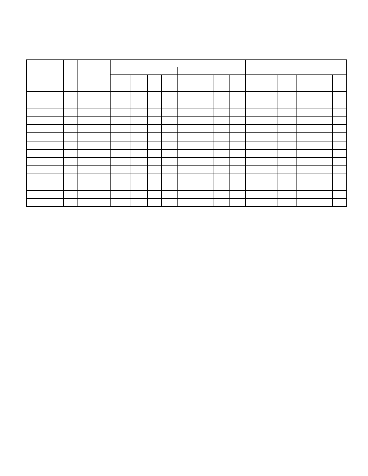
ELECTRICAL DATA
K30-KTM-PDI-3
- 5 -
08/14/12
KTM
HOT GAS DEFROST
FAN MOTOR(S)
MODEL
KTM115MG-S1 2 115/1/60 2.2 2.5 200 15 3.0 3.4 104 15 115/1/60 1300 11.3 14.1 15
KTM139MG-S1 2 115/1/60 2.2 2.5 200 15 3.0 3.4 104 15 115/1/60 1300 11.3 14.1 15
KTM172MG-S1 3 115/1/60 3.3 3.6 300 15 4.5 4.9 156 15 115/1/60 1860 16.2 20.3 25
KTM208MG-S1 3 115/1/60 3.3 3.6 300 15 4.5 4.9 156 15 115/1/60 1860 16.2 20.3 25
KTM236MG-S1 4 115/1/60 4.4 4.7 400 15 6.0 6.4 208 15 115/1/60 1860 16.2 20.3 25
KTM260MG-S1 4 115/1/60 4.4 4.7 400 15 6.0 6.4 208 15 115/1/60 2280 19.8 24.8 25
KTM295MG-S1 5 115/1/60 5.5 5.8 500 15 7.5 7.9 260 15 115/1/60 2280 19.8 24.8 25
KTM115MG-S2 2 208-230/1/60 1.0 1.1 200 15 2.0 2.3 104 15 208-230/1/60 1300 5.7 7.1 15
KTM139MG-S2 2 208-230/1/60 1.0 1.1 200 15 2.0 2.3 104 15 208-230/1/60 1300 5.7 7.1 15
KTM172MG-S2 3 208-230/1/60 1.5 1.6 300 15 3.0 3.3 156 15 208-230/1/60 1860 8.1 10.1 15
KTM208MG-S2 3 208-230/1/60 1.5 1.6 300 15 3.0 3.3 156 15 208-230/1/60 1860 8.1 10.1 15
KTM236MG-S2 4 208-230/1/60 2.0 2.1 400 15 4.0 4.3 208 15 208-230/1/60 1860 8.1 10.1 15
KTM260MG-S2 4 208-230/1/60 2.0 2.1 400 15 4.0 4.3 208 15 208-230/1/60 2280 9.9 12.4 15
KTM295MG-S2 5 208-230/1/60 2.5 2.6 500 15 5.0 5.3 260 15 208-230/1/60 2280 9.9 12.4 15
No.
FANS
of
POWER
SUPPLY
PSC-Standard ECM-Optional
TOTAL
MOTOR
FLA
M.C.A. Watts M.O.P
TOTAL
MOTOR
FLA
M.C.A. Watts M.O.P
DRAIN PAN HEATERS
POWER
SUPPLY
TOTAL
WATTS
60Hz
TOTAL
MOTOR
FLA
M.C.A. M.O.P
Page 6
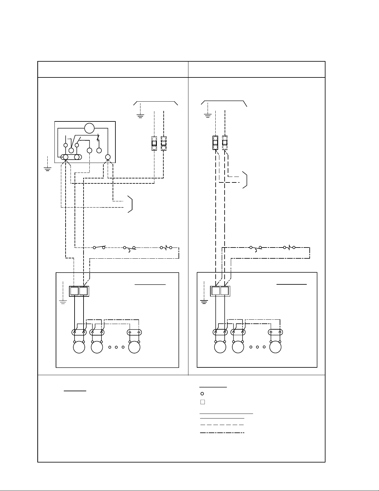
1-TM AD 03/08
TERMINAL BOARD
PUMP DOWN
WIRED ON EVAPORATOR .
2). USE 90°C WIRE (OR HIGHER)
EVAPORATOR FAN MOTORS AND DEFROST
HEATERS MUST NOT EXCEED MAXIMUM
VALUE SHOWN ON EVAPORATOR NAMEPLATE.
1). USE COPPER CONDUCTORS ONLY
3). OVERCURRENT PROTECTION FOR
4). MAY BE FACTORY INSTALLED-MOUNTED AND
NOTES
MTR
FAN
MTR
FAN
4
GND.
F
(IF USED)
SWITCH
CONDUCTORS/WIRING
FACTORY WIRING
WIRING BY OTHERS
BY OTHERS
OPTIONAL FACTORY OR
COMPLIANCE WITH ALL APPLICABLE LOCAL
ALL FIELD WIRING MUST BE DONE IN
AND NATIONAL CODES.
TERMINAL BOARD
NOTE #4
SPACE
THERMOSTAT
-COMPONENT TERMINAL
-TERMINAL BLOCK TERMINAL
FAN MOTOR
POWER
PLUGS
REFER TO
EVAPORATOR
DATA PLATE
FOR MOTOR
QUANTITY
MTR
FAN
TERMINALS
MTR
FAN
MTR
FAN
SOLENOID VALVE
EVAPORATOR
NOTE #4
SPACE
THERMOSTAT
N.C.
NOTE #4
LIQUID LINE
4
GND.
F
FAN MOTOR
POWER
PLUGS
REFER TO
EVAPORATOR
DATA PLATE
FOR MOTOR
QUANTITY
MTR
FAN
EVAPORATOR
N.C.
NOTE #4
LIQUID LINE
SOLENOID VALVE
WITH DEFROST TIME CLOCK
GND
132
4NX
TM
OR EQUIVALENT
DEFROST CLOCK
PARAGON # 8145
EVAPORATORS (IF APPLIC)
NAMEPLATE FOR ELECTRICAL
REFER TO EVAPORATOR
WITHOUT DEFROST TIME CLOCK
GND
IF(N)
TO MULTIPLE EVAPS
F
4
(IF APPLIC)
OMIT 2ND
BREAKER
NOTE #3
FUSE OR
FUSE
CIRCUIT
4
F
BREAKER
NOTE #3
CIRCUIT
FUSE OR
NAMEPLATE FOR ELECTRICAL
REFER TO EVAPORATOR
REQUIREMENTS
L2(N)
L1
REQUIREMENTS
GND
L1
L2(N)
TO MULTIPLE
IF(N)
2ND FUSE
OMIT
KTM
K30-KTM-PDI-3
- 6 -
08/14/12
WIRING DIAGRAM
AIR DEFROST - ALL VOLTAGES
60Hz
Page 7

2-TM ED 03/08
FOR ALL MODELS USING DEFROST HEATER CONTACTOR
1
GND.
2). USE 75°C WIRE (OR HIGHER)
3). OVERCURRENT PROTECTION FOR
1). USE COPPER CONDUCTORS ONLY
AND WIRED ON EVAPORATOR
EVAPORATOR FAN MOTORS AND
EVAPORATOR NAMEPLATE.
MAXIMUM VALUE SHOWN ON
4.) MAY BE FACTORY INSTALLED-MOUNTED
DEFROST HEATERS MUST NOT EXCEED
NOTES
JUMPER
ORANGE
TERMINAL BOARD
POWER PLUGS
EVAPORATOR
MOTOR QUANTITY
DATA PLATE FOR
DT-DEFROST TERM
FD-FAN DELAY
FANFAN
MTRMTR
FAN MOTOR
MTR
FAN
REFER TO
DEFROST TERMINATION
GND.
BK
4
BN
F
X
C
CONTROL
(10.0A MAX.)
& FAN DELAY
FD
RD
DT
N
3
EVAPORATOR
H1
H2 H3
FOR ALL MODELS WITHOUT DEFROST HEATER CONTACTOR
USING MAXIMUM 15A HEATER OVERCURRENT PROTECTION
N
21
LIQUID LINE
SOL VALVE
NOTE #4
N.C.
NOTE #4
PUMP DOWN
(IF USED)
SWITCH
(IF USED)
THERMOSTAT
SPACE
COMPR INTERLOCK
REFER TO EVAPORATOR
NAMEPLATE FOR ELECTRICAL
3
4X
TM
OR EQUIVALENT
DEFROST CLOCK
PARAGON # 8145
FUSE OR
GND
BREAKER
CIRCUIT
15A
REQUIREMENTS
L1
N
-TERMINAL BLOCK TERMINAL
COMPLIANCE WITH ALL APPLICABLE LOCAL
ALL FIELD WIRING MUST BE DONE IN
OR BY OTHERS
WIRING BY OTHERS
OPTIONAL FACTORY
FACTORY WIRING
AND NATIONAL CODES.
CONDUCTORS/WIRING
-COMPONENT TERMINAL
TERMINALS
MOTOR QUANTITY
DATA PLATE FOR
(10.0A MAX.)
DT-DEFROST TERM
FAN
MTR
FAN
MTR
FD-FAN DELAY
FAN MOTOR
MTR
FAN
EVAPORATOR
REFER TO
POWER PLUGS
DEFROST TERMINATION
& FAN DELAY
BK
CONTROL
FD
4
F
DT
BN
X
C
TERMINAL BOARD
RD
N
JUMPER
3
ORANGE
EVAPORATOR
H1
H3
H2
NOTE #4
N.C.
SWITCH
(IF USED)
PUMP DOWN
NOTE #4
SOL VALVE
LIQUID LINE
COMPR INTERLOCK
(IF USED)
THERMOSTAT
SPACE
DEFROST HEATER
T2
T1
C
L1
L2
CONTACTOR
NAMEPLATE FOR ELECTRICAL
GND
(IF APPLIC.)
REFER TO EVAPORATOR
FUSE OR
BREAKER
NOTE #3
CIRCUIT
3
2
X4
TM
N
DEFROST CLOCK
OR EQUIVALENT
PARAGON # 8145
REQUIREMENTS
FUSE OR
NOTE #3
BREAKER
CIRCUIT
L1
N
DEFROST HEATERS
L.H. COIL
BK
BK
BOTTOM
BOTTOM
BK
R.H. COIL
BK
BK
DEFROST HEATERS
BK
BOTTOM
L.H. COIL
BK
BOTTOM
R.H. COIL
BK
KTM
K30-KTM-PDI-3
- 7 -
08/14/12
WIRING DIAGRAM
ELECTRIC DEFROST -
230V (SINGLE EVAPORATOR)
60Hz
Page 8

* Fan delay not used on second evap / use fan contactor if total fan amps exceeds 10A
4.) MAY BE FACTORY INSTALLED-MOUNTED
FAN MOTOR
POWER PLUGS
REFER TO
EVAPORATOR
MOTOR QUANTITY
DATA PLATE FOR
3-TM ED CONTACTOR MULTI 03/08
3). OVERCURRENT PROTECTION FOR
1). USE COPPER CONDUCTORS ONLY
DEFROST HEATERS MUST NOT EXCEED
EVAPORATOR FAN MOTORS AND
AND WIRED ON EVAPORATOR
EVAPORATOR NAMEPLATE.
MAXIMUM VALUE SHOWN ON
2). USE 90°C WIRE (OR HIGHER)
NOTES
MTR
FANFAN
MTR MTR
FAN
DT-DEFROST TERM
FD-FAN DELAY
& FAN DELAY
(10.0A MAX.)
DEFROST TERMINATION
BK
GND.
4
BN
F
X
CONTROL
FD
RD
DT
C
N
COMPLIANCE WITH ALL APPLICABLE LOCAL
ALL FIELD WIRING MUST BE DONE IN
WIRING BY OTHERS
FACTORY WIRING
OPTIONAL FACTORY
AND NATIONAL CODES.
TERMINALS
CONDUCTORS/WIRING
OR BY OTHERS
-COMPONENT TERMINAL
-TERMINAL BLOCK TERMINAL
SECONDARY
EVAPORATOR
* Remove & Insulate
EVAPORATOR
FAN
MTR
PRIMARY
MTR
FANFAN
MTR
DATA PLATE FOR
MOTOR QUANTITY
REFER TO
EVAPORATOR
FD-FAN DELAY
DT-DEFROST TERM
POWER PLUGS
FAN MOTOR
H1
H2
GND.
4
F
N
BK
& FAN DELAY
CONTROL
(10.0A MAX.)
DEFROST TERMINATION
FD
RD
BN
DT
X
C
H1 H2
FUSE OR
NOTE #3
BREAKER
CIRCUIT
(IF USED)
SPACE
NOTE #4
THERMOSTAT
FOR ALL MODELS USING DEFROST HEATER CONTACTOR
COMPR INTERLOCK
REFER TO EVAPORATOR
PUMP DOWN
(IF USED)
SWITCH
DEFROST CLOCK
PARAGON # 8145
OR EQUIVALENT
3
12
X4
N
TM
DEFROST HEATER
LIQUID LINE
SOL VALVE
NOTE #4
N.C.
NOTE #3
BREAKER
CIRCUIT
FUSE OR
T1
L1
C
CONTACTOR
T2
L2
REQUIREMENTS
L1
GND
FUSE OR
CIRCUIT
NOTE #3
BREAKER
L2
NAMEPLATE FOR ELECTRICAL
DEFROST HEATERS
L.H. COIL
BK
BOTTOM
BK
R.H. COIL
BOTTOM
BK
BK
DEFROST HEATERS
BK
BOTTOM
L.H. COIL
BK
BK
BK
BOTTOM
R.H. COIL
KTM
K30-KTM-PDI-3
- 8 -
08/14/12
WIRING DIAGRAM
ELECTRIC DEFROST -
230V (MULTI EVAPORATOR)
60Hz
Page 9

CONTROL
**DEFROST TERMINATION
4.) MAY BE FACTORY INSTALLED-MOUNTED
AND WIRED ON EVAPORATOR
4-TM HG 03/08
2). USE 90°C WIRE (OR HIGHER)
EVAPORATOR NAMEPLATE.
MAXIMUM VALUE SHOWN ON
3). OVERCURRENT PROTECTION FOR
1). USE COPPER CONDUCTORS ONLY
DEFROST HEATERS MUST NOT EXCEED
EVAPORATOR FAN MOTORS AND
NOTES
MTR
FANFAN
MTR
BK
GND.
4
F
X
OR BY OTHERS
COMPLIANCE WITH ALL APPLICABLE LOCAL
ALL FIELD WIRING MUST BE DONE IN
WIRING BY OTHERS
FACTORY WIRING
OPTIONAL FACTORY
AND NATIONAL CODES.
THE CONTROL CLOSES WHEN REACHES 55` F (20 F DIFF)
OPTIONAL FACTORY WIRED OR BY OTHERS
ON REVERSE CYCLE LOCATED AT SUCTION LINE.
(ANYTIME THE TEMPERATURE OF THE INCOMING
EVAPORATOR FANS AND ENERGIZES THE
THE FAN/HEATER CONTROL DE-ENERGIZES THE
NOTE: DURING THE HOT GAS DEFROST CYCLE
EVAPORATOR
FAN MOTOR
POWER PLUGS
REFER TO
EVAPORATOR
MOTOR QUANTITY
DATA PLATE FOR
MTR
FAN
CONDUCTORS/WIRING
-COMPONENT TERMINAL
-TERMINAL BLOCK TERMINAL
TERMINALS
LOCATED ON TUBE END SHEET
**DEFROST TERMINATION
CONTROL
RD
DRAIN PAN HEATER
RD
RD
*FAN HEATER
CONTROL
C
BN
N
H1
REFRIGERANT GAS IS ABOVE 50° F).
DRAIN PAN HEATER.
CONTROL
*FAN HEATER
REFER TO SPECIFIC SYSTEM
WIRING DIAGRAM (BY OTHERS)
FOR FIELD CONTROL WIRING
USING MAXIMUM 15A HEATER OVERCURRENT PROTECTION
15A
FUSE OR
FAN MOTOR / HEATER WIRING
BREAKER
CIRCUIT
NAMEPLATE FOR ELECTRICAL
L2(N)
REFER TO EVAPORATOR
GND
L1
REQUIREMENTS
BK
BK
H2
KTM
K30-KTM-PDI-3
- 9 -
08/14/12
WIRING DIAGRAM
REVERSE CYCLE DEFROST - 230V
60Hz
Page 10

KTM
K30-KTM-PDI-3
- 10 -
08/14/12
MECHANICAL DATA
60Hz
TUBE CONNECTIONS
MODEL
KTM115M 7/8 22 1/2 13 1/2 13 110 50
KTM139M 7/8 22 1/2 13 1/2 13 116 53
KTM172M 7/8 22 1/2 13 1/2 13 150 68
KTM208M 1 1/8 29 1/2 13 1/2 13 157 71
KTM236M 1 1/8 29 1/2 13 1/2 13 164 74
KTM260M 1 1/8 29 7/8 22 5/8 16 191 87
KTM295M 1 1/8 29 7/8 22 5/8 16 198 90
KTM105L 7/8 22 1/2 13 1/2 13 110 50
KTM124L 1 1/8 29 1/2 13 1/2 13 116 53
KTM153L 1 1/8 29 1/2 13 1/2 13 150 68
KTM188L 1 1/8 29 7/8 22 5/8 16 157 71
KTM210L 1 1/8 29 7/8 22 5/8 16 164 74
KTM235L 1 3/8 35 7/8 22 5/8 16 191 87
KTM265L 1 3/8 35 7/8 22 5/8 16 198 90
SUCTION (OD) DISTRIBUTOR INLET HOT GAS SIDE (OD)
Inches mm Inches mm Inches mm Lbs. Kgs
APPROX. SHIPPING WEIGHT
Page 11

KTM
on all suction headers inside
"C"
"D"
3). 1/4" O.D. external equalizer line
Drain fitting.
7/8 (22 mm)
hole & knockout
Suction line
6-1/4
and service access fitting included
all models.
Air defrost, Electric, and
NOTES: 1). Dimensions shown are typical for
opposite to the piping end on
2). Electrical connection end is
"B"
MAX
AIR
AIR
"C"
"D"
SIDE VIEW
Unit cooler is to be supported at all mounting points
MOUNTING HOLES (3/8" DIA.) & PIPING CONNECTION
"E"
26 1/2
AIR
OUT
Coil
AIR
AIR IN
AIR
Coil
3-3/8
7/8 (22 mm)
knockouts
3 each side
Hinged
Drain pan/Fan panel
OUT
AIR
26 15/16
MOUNTING HOLES
28 3/16
END VIEW
"A"
1 13/16
L.H.
R.H.
end compartment
3/4" FPT
Hot Gas defrost
K30-KTM-PDI-3
- 11 -
08/14/12
DIMENSIONAL DATA
Inches (mm)
60Hz
DIMENSIONS
MODEL
NUMBER
NO.FANS
KTM115M 2 67 1/2 1715 8 11/16 221 27 1/2 699 - - - -
KTM139M 2 67 1/2 1715 8 11/16 221 27 1/2 699 - - - -
KTM172M 3 93 1/2 2375 8 11/16 221 40 1/2 1029 - - - -
KTM208M 3 93 1/2 2375 8 11/16 221 40 1/2 1029 - - - -
KTM236M 4 93 1/2 2375 8 11/16 221 40 1/2 1029 - - - -
KTM260M 4 113 1/2 2883 8 11/16 221 - - 40 1/2 1029 20 508
KTM295M 5 113 1/2 2883 8 11/16 221 - - 40 1/2 1029 20 508
KTM105L 2 67 1/2 1715 8 11/16 221 27 1/2 699 - - - -
KTM124L 2 67 1/2 1715 8 11/16 221 27 1/2 699 - - - -
KTM153L 3 93 1/2 2375 8 11/16 221 40 1/2 1029 - - - -
KTM188L 3 93 1/2 2375 8 11/16 221 40 1/2 1029 - - - -
KTM210L 4 93 1/2 2375 8 11/16 221 40 1/2 1029 - - - -
KTM235L 4 113 1/2 2883 8 11/16 221 - - 40 1/2 1029 20 508
KTM265L 5 113 1/2 2883 8 11/16 221 - - 40 1/2 1029 20 508
* Reducer supplied to accomodate 1/2” or 7/8” TXV outlet connection.
A B C D E
in mm in mm in mm in mm in mm
Page 12

KTM
A
B
WALL
WALL
CEILING
D
C
A
A
D
TOP VIEW
TOP VIEW
SIDE VIEW
SIDE VIEW
K30-KTM-PDI-3
- 12 -
08/14/12
RECOMENDED INSTALLATION
CLEARANCES
60Hz
DIMENSION A B C D
MINIMUM
Maximum
ft. 2 2 6 3
cm. 61 61 183 92
ft. - 7 40 20
cm. - 210 1200 600
Page 13

KTM
K30-KTM-PDI-3
- 13 -
08/14/12
NOZZLE SELECTIONS
60Hz
Nozzle Selections (Factory installed)
For all applications and refrigerants
Model Nozzle
KTM115M L-1
KTM139M L-1 1/2
KTM172M L-1 1/2
KTM208M L-2
KTM236M L-2
KTM260M G-2 1/2
KTM295M G-3
MEDIUM TEMP - EXPANSION VALVE SELECTION
SPORLAN
MODEL TD
KTM115M
KTM139M
KTM172M
KTM208M
KTM236M
KTM260M
KTM295M
CAPACITY @
25°F SST
10 11,500 EGSE-1-C EGVE-1-C
15 17,250 EGSE-1-1/2-C EGVE-1-1/2-C
10 13,900 EGSE-1-C EGVE-1-C
15 20,850 EGSE-2-C EGVE-2-C
10 17,200 EGSE-1-1/2-C EGCE-1-1/2-C
15 25,800 SSE-3-C EGVE-3-C
10 20,800 EGSE-1-1/2-C EGCE-1-1/2-C
15 31,200 SSE-3-C EGVE-3-C
10 23,600 EGSE-2-C EGVE-2-C
15 35,400 SSE-3-C EGVE-3-C
10 26,000 EGSE-2-C EGVE-2-C
15 39,000 SSE-4-C EGVE-3-C
10 29,500 SSE-3-C EGVE-3-C
15 44,250 SSE-4-C SVE-4-C
* For medium temp. R-507, refrigerant designation changes
from ‘S’ to ‘P’.
R404A
R507
*
R22
R407C
Model Nozzle
KTM105L L-1 1/2
KTM124L L-2
KTM153L L-2
KTM188L G-2 1/2
KTM210L G-3
KTM235L E-3
KTM265L E-4
DANFOSS
MODEL TD
KTM115M
KTM139M
KTM172M
KTM208M
KTM236M
KTM260M
KTM295M
CAPACITY @
25°F SST
10 11,500 TUAE-R404A-6-N TUAE-R22-6-N
15 17,250 TUAE-R404A-8 TUAE-R22-7-N
10 13,900 TUAE-R404A-7-N TUAE-R22-6-N
15 20,850 TUAE-R404A-8-N TUAE-R22-7-N
10 17,200 TUAE-R404A-7-N TUAE-R22-7-N
15 25,800 TUAE-R404A-9-N TUAE-R22-8-N
10 20,800 TUAE-R404A-8-N TUAE-R22-7-N
15 31,200 TUAE-R404A-9-N TUAE-R22-8-N
10 23,600 TUAE-R404A-8-N TUAE-R22-8-N
15 35,400 TCAE-R404A-1-N TUAE-R22-9-N
10 26,000 TUAE-R404A-9-N TUAE-R22-8-N
15 39,000 TCAE-R404A-2-N TUAE-R22-9-N
10 29,500 TUAE-R404A-9-N TUAE-R22-8-N
15 44,250 TCAE-R404A-2-N TUAE-R22-9-N
R404A
R507
R22
R407C
ALCO
MODEL TD
KTM208M
KTM236M
KTM260M
KTM295M
CAPACITY @
25°F SST
10 20,800 HFESC - 1-1/2 - SC HFESC - 2 - HC
15 31,200 HFESC- 3-1/2 - SC HFESC - 3- HC
10 23,600 HFESC - 2 - SC HFESC - 2 - HC
15 35,400 HFESC- 3-1/2 - SC HFESC - 3 - HC
10 26,000 HFESC - 2 - SC HFESC - 2-1/2 - HC
15 39,000 HFESC- 3-1/2 - SC HFESC - 3 - HC
10 29,500 HFESC - 2 - SC HFESC - 2-1/2 - HC
15 44,250 HFESC- 3-1/2 - SC HFESC - 3 - HC
ALL TXV Selections based on 90-100°F liquid.
R404A
R507
R22
R407C
Page 14

KTM
K30-KTM-PDI-3
- 14 -
08/14/12
LOW TEMP
EXPANSION VALVE SELECTION
60Hz
SPORLAN -
Model 0°F Evap -10°F Evap -20°F Evap
KTM105L EGSE-1-C EGSE-1-ZP EGSE-1-ZP
KTM124L EGSE-1-C EGSE-1-ZP EGSE-1-ZP
KTM153L EGSE-1-1/2-C EGSE-1-1/2-ZP EGSE-1-1/2-ZP
KTM188L EGSE-1-1/2-C EGSE-2-ZP EGSE-2-ZP
KTM210L EGSE-2-C EGSE-2-ZP EGSE-2-ZP
KTM235L EGSE-2-C EGSE-2-ZP SSE-3-ZP
KTM265L SSE-3-C SSE-3-ZP SSE-3-ZP
For low temp. R-507, refrigerant designation changes from ‘SE’ to ‘PE’.
*
DANFOSS -
Model 0°F Evap -10°F Evap -20°F Evap
KTM105L TUAE-R404A-7-N TUAE-R404A-8-NM TUAE-R404A-8-NM
KTM124L TUAE-R404A-7-N TUAE-R404A-8-NM TUAE-R404A-8-NM
KTM153L TUAE-R404A-8-N TUAE-R404A-8-NM TUAE-R404A-9-NM
R404A
R404A
R507
R507
KTM188L TUAE-R404A-9-N TUAE-R404A-9-NM TCAE-R404A-1-NM
KTM210L TUAE-R404A-9-N TUAE-R404A-9-NM TCAE-R404A-1-NM
KTM235L TUAE-R404A-9-N TCAE-R404A-1-NM TCAE-R404A-1-NM
KTM265L TCAE-R404A-1-N TCAE-R404A-1-NM TCAE-R404A-2-NM
ALCO -
Model 0°F Evap -10°F Evap -20°F Evap
KTM105L HFESC - 1 - SC HFESC - 1-1/4 - SW45 HFESC - 1-1/4 - SW45
KTM124L HFESC - 1 - SC HFESC - 1-1/4 - SW45 HFESC - 1-1/2 - SW45
KTM153L HFESC - 1-1/4 - SC HFESC - 1-1/2 - SW45 HFESC - 2 - SW45
KTM188L HFESC - 1-1/2 - SC HFESC - 2 - SW45 HFESC - 2 - SW45
KTM210L HFESC - 1-1/2 - SC HFESC - 2 - SW45 HFESC - 2 - SW45
KTM235L HFESC - 2 - SC HFESC - 2 - SW45 HFESC - 3-1/2 - SW45
KTM265L HFESC - 2 - SC HFESC - 3-1/2 - SW45 HFESC - 3-1/2 - SW45
* For low temp. R-507, refrigerant designation changes from ‘SC’ to ‘PC’.
R404A
R507
Page 15

REVERSE CYCLE DEFROST
ELECTRIC DRAIN PAN HEATER
EVAPORATOR COIL
G
OPT1
FACTORY PIPING
CHECK VALVE SHIPPED LOOSE
CHECK
VALVE
DISTRIBUTOR
TXV
REVERSE CYCLE DEFROST
HOT GAS
ENTERING
ELECTRIC DRAIN PAN HEATER
STD-G
FACTORY PIPING
LEAVING
HOT GAS
WITH CHECK VALVE LOOSE
EVAPORATOR COIL
DISTRIBUTOR
CHECK
VALVE
ENTERING
HOT GAS
WITH DRAIN PAN HEATERWITH DRAIN PAN HEATER
WITH TXV FACTORY INSTALLED
HOT GAS
LEAVING
KTM
K30-KTM-PDI-3
- 15 -
08/14/12
FAN/HEATER CONTROL AND DEFROST
TERMINATION CONTROL POSITION
60Hz
HOT GAS DEFROST (REVERSE CYCLE)
Page 16

KTM
K30-KTM-PDI-3
- 16 -
08/14/12
INSTALLATION INSTRUCTIONS
60Hz
INSTALLATION
The installation and start-up of Two-Way Unit Coolers should only
be performed by qualied refrigeration mechanics.
This equipment should be installed in accordance with all applica-
ble codes, ordinances and local by-laws.
INSPECTION
Inspect all equipment before unpacking for visible signs of dam-
age or loss. Check shipping list against material received to
ensure shipment is complete.
IMPORTANT: Remember, you, the consignee, must make any
claim necessary against the transportation company. Shipping
damage or missing parts, when discovered at the outset, will prevent later unnecessary and costly delays.
If damage or loss during transport is evident, make claim to
carrier, as this will be their responsibility, not the
manufacturer’s.
Should carton be damaged, but damage to equipment is not
obvious, a claim should be led for “concealed damage” with the
carrier.
IMPORTANT: The electrical characteristics of the unit should
be checked at this time to make sure they correspond to those
ordered and to electrical power available at the job site.
Save all shipping papers, tags and instruction sheets for
reference by installer and owner.
APPLICATION
Two-Way Unit Coolers are designed for use in coolers and freez-
ers such as reach in boxes, walk-in rooms and any other cooler
applications where a low velocity, uniform air ow is required. The
compact and low height unit provides maximum useable product
storage space.
At room temperatures above 34
peratures no lower than 27
coil will accomplish the defrost (Air Defrost).
At room temperatures 34
frosting is required ( Electric defrost) . These will require the use
of :
1. Time Clock (to initiate and terminate the defrost cycle ),
2. Defrost termination thermostat (to prevent unnecessary
prolonged heating and steaming of the coil once all the frost
and ice has melted). And if a freezer,
3. Fan delay thermostat (to prevent evaporator fans starting up
right away and blowing water on to the fan blades, guards
and oor).
This evaporator coil must not be exposed to any abnormal environments (acidic or caustic) that can result in coil corrosion and
leaks. Consult factory for optional baked on phenolic protective
coatings. These unit coolers are for use primarily on R134a, R22
and R404A refrigerants and their approved alternatives / replacements.
o
F (1.1 oC) and evaporating tem-
o
F (-2.8 oC) the air owing through the
o
F and below ( to -10 oF) positive de-
LOCATION
The unit location in the room should be selected to ensure
uniform air distribution throughout the entire space to be
refrigerated. Be sure that the unit does not draw air in, or
blow directly out, through an opened door and that the product
does not obstruct the free circulation of air. Allow a minimum
of 24” clearance at each end. Two-Way Unit Coolers draw air
through the fans and discharge air through both coils.
Consideration should be given to the coil location in order to
minimize the piping run length to the condensing unit and oor
drain.
EXPANSION VALVE (TXV) SELECTION
All units require the use of an externally equalized
expansion valve. (A 1/4” (6 mm) O.D. equalizer line has been
provided on the coil) TX valves should not be selected strictly
by their nominal ton rating. (This rating is based at a specic
pressure differential and entering liquid temperature). Since
applications will differ it is suggested the following selection
procedure be followed.
1. Determine actual unit cooler BTUH or KW (thermal).
The nominal rating is based at 10
(Room Temp. minus Evap. Temp.). Note that a higher /
lower operating T.D.will increase / decrease this capacity
rating by their direct ratio.
2. Determine the pressure drop across the valve by
subtracting the suction (evaporating) pressure from the
high side liquid pressure. Note: Also subtract the
distributor pressure loss (use approx. 25 psig (1.1 bar)
for R134a and 35 psig (2.4 bar) for R22, R404A, R507).
3. Estimate entering liquid temperature. Temperatures
lower than 100
ratings. Refer to valve manufacturer’s specs for details.
4. Select valve from the valve manufacturer selection charts
for the appropriate refrigerant, evaporating temp and
pressure drop.
5. After following the manufacturer’s installation instructions
and after the room has reached the desired temperature
the valve superheat should be checked. This will conrm
that the evaporator is operating properly and performing
to maximum efciency. The superheat should be
around 5 (2.7°C) to 8
(5.5 to 6.6°C) T.D. Too high or low a super heat will result
in unsatisfactory system performance and possible
compressor problems.
°
F (37.7 °C) increase valve capacity
O
F (4.4°C) for a 10 to 12 OF
O
F T.D. (5 .5°C)
NOZZLE INSTALLATION
All Two-Way unit coolers have nozzles installed at factory. For
nozzle selection refer to selection table. In case it is required to
install the nozzle at some point in the future, the nozzle retainer
clip (in distributor) must be removed before inserting nozzle.
Re-install clip ensuring nozzle is properly in place.
Page 17

KTM
K30-KTM-PDI-3
- 17 -
08/14/12
INSTALLATION INSTRUCTIONS (cont’d)
60Hz
MOUNTING
Refer to dimensional drawing for recommended mounting ar-
rangements. Formed mounting channels are provided for ush
mounting to the ceiling. Ensure adequate clearance (at least
24” (600 mm)) is provided at each end (to enable access to the
electrical and refrig. compartments).
Ensure that the ceiling is level since the drain pan has
been sloped for drainage during the defrost cycle.
DRAIN LINE
The drain line should be run from the drain connection, sloping
at least 1/4” (6 mm) per foot. A trap in a warm area outside the
room will allow proper draining through the tubing. Connection
should be made to proper drainage facilities that comply with
local regulations.
To prevent freeze-up when the temperature of the refrigerated
space is 35
along its run inside the cold room. The heated drain line should
be insulated. It is recommended that the heater be energized
at all times. A heat input of 20 watts per foot in a 28°F (-2.2°C)
room, is satisfactory. Drain line heaters are not required for
constant room temperature above 35°F (1.6°C).
Ensure that the drain line has sufcient slope for proper
drainage (prevention of ice build up/blockage in pan).
o
F (1.7 °C) or lower, the drain line should be heated
PIPING
Refrigerant line sizes are important and may not be the same
size as the coil connections. Consult “Recommended refriger-
ant line sizes” charts in any standard reference book for proper
line sizing.
Refrigerant piping and control system should be designed to
prevent possible liquid slugging (from oil or refrigerant) of the
compressors on start-up after the defrost cycle. On Hot Gas
Defrost Systems the suction accumulator should be at least 2.5
times the coils operating charge.
See Dimensional data for line locations. Reverse Cycle mod-
els include a check valve (unmounted) packaged along with
the nozzle in the refrig. connection compartment end panel.
WIRING
Wire system in accordance with governing standards and local
codes. See data and wiring diagrams on pages 7 to 12 for wir-
ing arrangement. Electrical wiring is to be sized in accordance
with minimum circuit ampacity rating (MCA).
For ease of identifying the proper wiring terminal, unit wiring is
color coded and terminal block connections are identied.
SYSTEM CHECK
Before Start-Up:
1. All wiring should be in accordance with local codes.
2. Refrigerant lines should be properly sized.
3. Off cycle defrost and electric defrost systems preferably
must include a liqud line solenoid valve and suction
accumulator.
4. Thorough evacuation and, dehydration has been
performed.
5. The suction, discharge, and receiver service valves must
be open.
6. The system preferably must include a liquid line drier
moisture indicator and suction lter.
7. Pour enough water into the drain pan to allow a good check
on drainage and seal the trap.
After Start-Up:
1. Check the oil level to be sure the oil charge is correct.
2. On initial start up the fans do not start until coil
temperature is pulled down to approximately 35 °F (1.7 °C)
on the hot gas coil. Also, it is normal for the fans to cycle a
few times until the room temperature is pulled down.
3. Fan/Heater control and defrost termination control is
factory installed for reverse cycle defrost operation.
4. In general, evaporators running with a TD of 10 °F should
have a superheat reading of 5° to 8 °F (2.7 °C to 4.4 °C).
For evaporators with a higher TD, the superheat should be
8° to 12°F (4.4 °C to 6.6 °C).
5. Heavy moisture loads are usually encountered when
starting the system for the rst time. This will cause a rapid
build-up of frost on the unit cooler. During the initial pull
down, we suggest that the frost build-up be watched and
defrosted manually as required. This may be done by
rotating the inner dial on the timer until the pin in the outer
dial is directly opposite the timer pointer. (Paragon 8145-
20 Timer by others).
6. Observe that the system goes through at least one
complete DEFROST CYCLE.
MAINTENANCE
The unit should be periodically inspected for any dirt or
build-up on the n surface and cleaned if necessary with a soft
whisk or brush. Also ensure coils inner and outer drain pans
do not have any ice build-up from improper defrost operation.
When replacing heater elements rst remove heater retainer
brackets and heater clips.
Page 18

GENERIC SERVICE PARTS LIST
K30-KTM-PDI-3
- 18 -
08/14/12
KTM
MODEL NUMBER PSC Motor EC Motor
MEDIUM
TEMP
KTM 115M KTM 105L 1073403 1073405 1087600 1091176 1091 177 1087600 1073456 1073642 1070854-003
KTM 139M KTM 124L 1073403 1073405 1087600 1091176 1091 177 1087600 1073456 1073642 1070854-003
KTM 172M KTM 153L 1073403 1073405 1087600 1091176 1091 177 1087600 1073456 1073643 1070854-002
KTM 208M KTM 188L 1073403 1073405 1087600 1091176 1091 177 1087600 1073456 1073643 1070854-002
KTM 236M KTM 210L 1073403 1073405 1087600 1091176 1091 177 1087600 1073456 1043315 1070854-002
KTM 260M KTM 235L 1073403 1073405 1087600 1091176 1091 177 1087600 1073456 1073644 1070854-001
KTM 295M KTM 265L 1073403 1073405 1087600 1091176 1091 177 1087600 1073456 1043316 1070854-001
Terminal Board - 1048825
Fan Delay / Defrost Terminaltion Control - 1071280 ( electric defrost models only)
Fan Delay / Heater Control - 1073640 (hot gas models only)
LOW
TEMP
Motor
115V
Motor
230V
Fan
Blade
Motor
115V
Motor
230V
Fan
Blade
Fan
Guard
60Hz
Wire
Harness
* Drain Pan
Heater
(if appl)
Page 19

Finished Goods Warranty
K30-KTM-PDI-3
- 19 -
08/14/12
The terms and conditions as described below in the General Warranty Policy cover all products
manufactured by National Refrigeration.
GeneraL Warranty PoLiCy
Subject to the terms and conditions hereof, the Company warrants all Products, including Service
Parts, manufactured by the Company to be free of defects in material or workmanship, under nor-
mal use and application for a period of one (1) year from the original date of installation, or eighteen
(18) months from the date of shipment from the Company, whichever occurs rst. Any replacement
part(s) so supplied will be warranted for the balance of the product’s original warranty. The part(s) to
be replaced must be made available in exchange for the replacement part(s) and reasonable proof
of the original installation date of the product must be presented in order to establish the effective
date of the warranty, failing which, the effective date will be based upon the date of manufacture plus
thirty (30) days. Any labour, material, refrigerant, transportation, freight or other charges incurred in
connection with the performance of this warranty will be the responsibility of the owner at the cur-
rent rates and prices then in effect. This warranty may be transferred to a subsequent owner of the
product.
this Warranty does not CoVer
(a) Damages caused by accident, abuse, negligence, misuse, riot, re, ood, or Acts of God (b) damages
caused by operating the product in a corrosive atmosphere (c) damages caused by any unauthorized
alteration or repair of the system affecting the product’s reliability or performance (d) damages caused
by improper matching or application of the product or the product’s components (e) damages caused by
failing to provide routine and proper maintenance or service to the product (f) expenses incurred for the
erecting, disconnecting, or dismantling the product (g) parts used in connection with normal maintenance,
such as lters or belts (h) products no longer at the site of the original installation (i) products installed
or operated other than in accordance with the printed instructions, with the local installation or building
codes and with good trade practices (j) products lost or stolen.
No one is authorized to change this WARRANTY or to create for or on behalf of the Company any
other obligation or liability in connection with the Product(s). There is no other representation, warranty
or condition in any respect, expressed or implied, made by or binding upon the Company other than
the above or as provided by provincial or state law and which cannot be limited or excluded by such
law, nor will we be liable in any way for incidental, consequential, or special damages however caused.
The provisions of this additional written warranty are in addition to and not a modication of or subtraction
from the statutory warranties and other rights and remedies provided by Federal, Provincial or State laws.
PROJECT INFORMATION
System
Model Number Date of Start-Up
Serial Number Service Contractor
Refrigerant Phone
Electrical Supply Fax
Page 20

“AS BUILT” SERVICE PARTS LIST
08/14/12
Service Parts List
Label
To Be Attached
HERE
NATIONAL REFRIGERATION &
AIR CONDITIONING CANADA CORP.
CANADA
159 ROY BLVD., BRANTFORD, ONTARIO, CANADA N3R 7K1
PHONE: 1-800-463-9517 (519)751-0444 FAX (519)753-1140
Due to National Refrigeration’s policy of continuous product improvement, we reserve the right to make changes without notice.
USA
985 WHEELER WAY, LANGHORNE, PA. 19047 USA
PHONE: 1-888-KEEPUS1 OR 1-888-533-7871
 Loading...