

Page 1
PRODUCT DATA &
06/01/12
INSTALLATION
Bulletin K30-KTL-PDI-3
1087830
Latest product updates and further information
at www.keepriterefrigeration.com
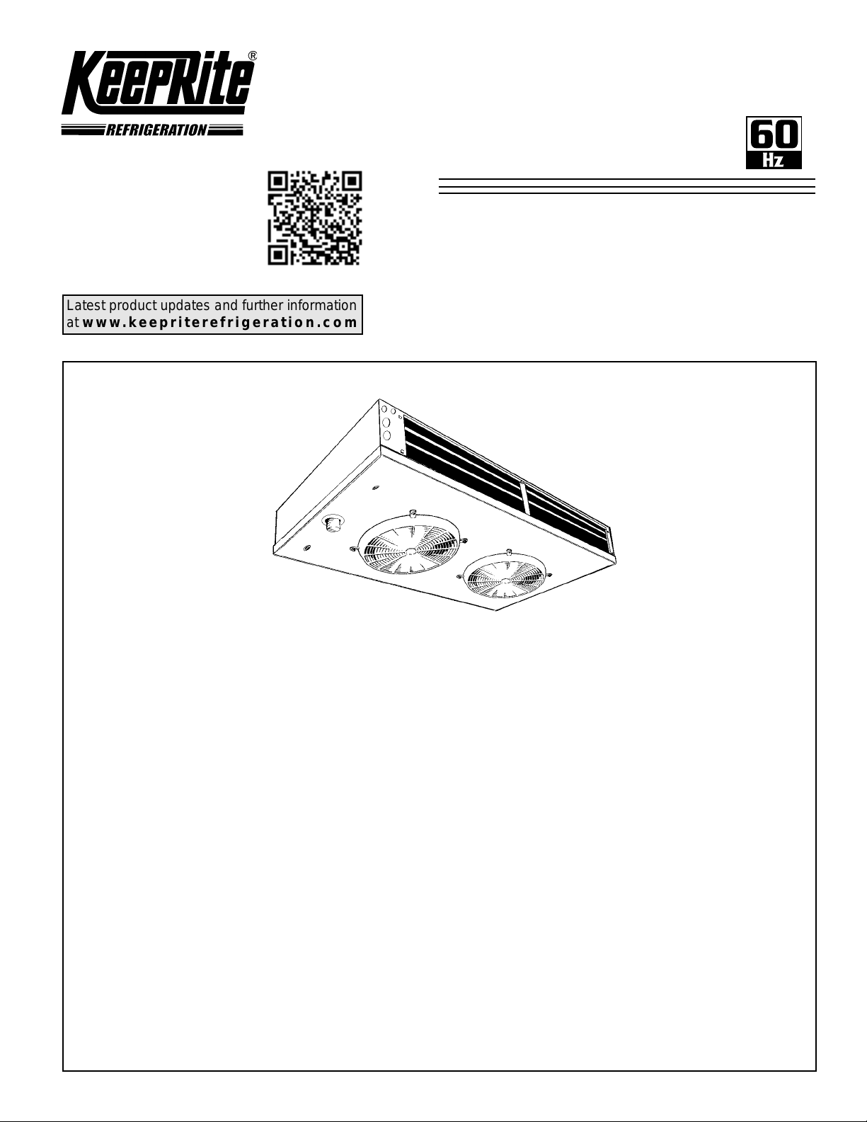
KTL Two-Way
Low Prole
Evaporators
High, Medium and Low
Temperature
-10°F (-23.3 °C) and above
Air or Electric Defrost
Electrical Power: 115/1/60, 208-230/1/60
Applications
CONTENTS
Nomenclature.................................................................................................................. 2
Features........................................................................................................................... 2
Capacity Data (Imperial and Metric)................................................................................ 3
Electrical Data................................................................................................................. 4 - 5
Wiring Diagrams.............................................................................................................. 6 - 8
Dimensional Data........................................................................................................... 9 - 10
TXV Selection................................................................................................................. 11 - 12
Installation Instructions................................................................................................... 13 - 14
Generic Service Parts List.............................................................................................. 14
Warranty......................................................................................................................... 15
Project Information......................................................................................................... 15
“As Built” Service Parts List............................................................................................ BACK
Page
Page 2
Model Name
K30-KTL-PDI-3
- 2 -
06/01/12
K = KeepRite
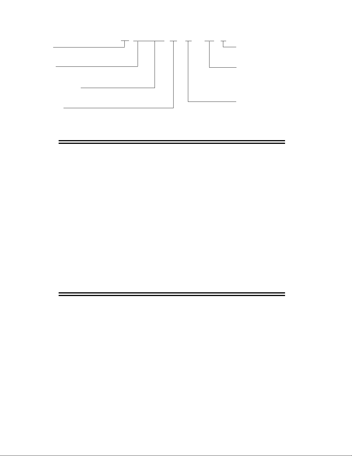
NOMENCLATURE
K TL 1 1 5 M A - S1 A
Design Version
Product Name
TL = Two Way Low Prole Evaporator
X 100 = Nominal Capacity
(10°F TD, 60Hz), Btu/H
Evap Temp Range
M = Medium Temp (10 - 45°F), 8 FPI.
L = Low Temp(-20 - 0°F), 8 FPI.
STANDARD FEATURES
• Low height compact size maximizes useable
storage space
• Dual refrigeration coils and two-way air
distribution reduces air velocities to minimize
product dehydration.
• Air enters through fan and discharges two ways
out of each coil side.
Unit Electrical Designaton.
S1 = 115/1/60
S2 = 208-230/1/60
S6 = 200-220/1/50
Defrost Type.
A = Air Defrost
E = Electric Defrost
• Rugged heavy duty motor mount reduces
vibration and noise.
• Electric defrost models include factory installed
defrost termination and fan delay thermostat.
• NSF approved “ush to ceiling mount”
• Refrigerants R404A/R507, R22 and R407C.
• Internally enhanced tube
OPTIONAL FEATURES
• PSC Motors available on all models • EC Motors available for Medium Temperature
models 038, 060, 077 & 115 and Low
Temperature models 033, 052, 066 & 099
Page 3
KTL
K30-KTL-PDI-3
- 3 -
06/01/12
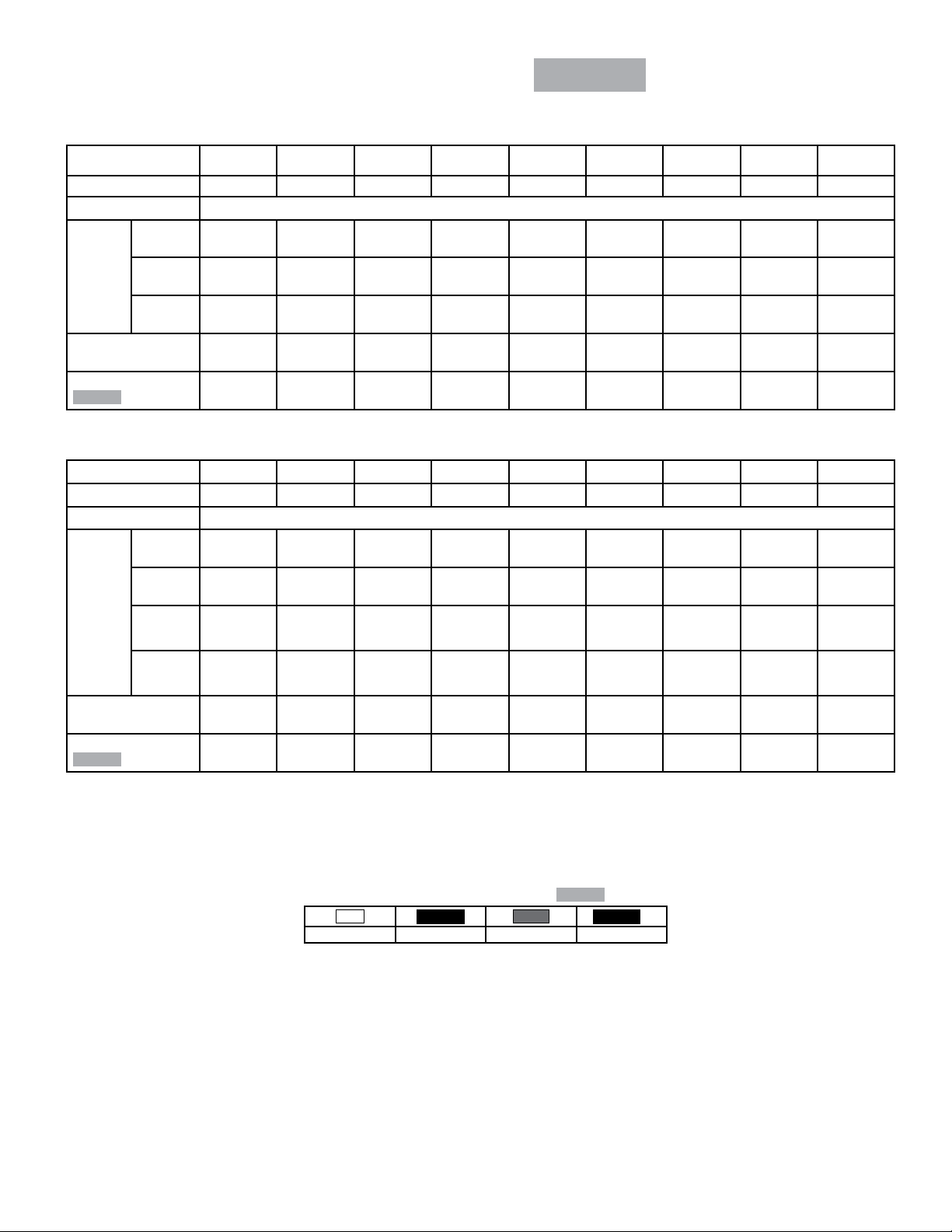
CAPACITY DATA
R404A
60Hz
MEDIUM TEMPERATURE MODELS - CAPACITY *
KTL010M KTL015M KTL020M KTL025M KTL032M KTL038M KTL060M KTL077M KTL115M
Number of Fans 1 1 1 1 1 1 2 2 3
Capacity * BTUH (watts)
+ 20/25
Evap
Temp
°F(°C)
Air Flow CFM (L/s)
Refrigerant Charge
R404A
(-3.9/-6.7)
15
(-9.4)
10
(-12.2)
Lbs (Kg)
LOW TEMPERATURE MODELS - CAPACITY *
Number of Fans 1 1 1 1 1 1 2 2 3
Capacity * BTUH (watts)
0
(-17.8)
-10
Evap
Temp
°F(°C)
(-23.3)
-15
(-26.1)
950
(278)
940
(275)
930
(273)
130
(61.4)
0.4
(0.18)
KTL009L KTL013L KTL017L KTL021L KTL028L KTL033L KTL052L KTL066L KTL099L
910
(267)
880
(258)
870
(255)
1450
(425)
1430
(419)
1420
(416)
180
(85.0)
0.5
(0.23)
1340
(393)
1300
(381)
1280
(375)
2000
(586)
1970
(577)
1960
(574)
237
(112)
0.7
(0.32)
1820
(533)
1770
(519)
1730
(507)
2500
(733)
2460
(721)
2450
(718)
270
(127)
0.8
(0.36)
2250
(659)
2180
(639)
2140
(627)
3200
(938)
3150
(923)
3140
(920)
440
(208)
0.9
(0.41)
3000
(879)
2910
(853)
2860
(838)
3800
(1114)
3740
(1096)
3720
(1090)
440
(208)
1.2
(0.55)
3530
(1035)
3430
(1005)
3370
(988)
6000
(1758)
5910
(1732)
5880
(1723)
928
(438)
1.4
(0.64)
5560
(1629)
5410
(1586)
5300
(1553)
7700
(2257)
7580
(2221)
7550
(2213)
807
(381)
2.3
(1.05)
7060
(2069)
6860
(2010)
6730
(1972)
11500
(3370)
11330
(3320)
11270
(3303)
1242
(586)
3.4
(1.55)
10590
(3104)
10300
(3019)
10100
(2960)
-20
(-28.9)
Air Flow CFM (L/s)
Refrigerant Charge
R404A
Lbs (Kg)
Capacities rated using R404A with 10° F (5.6°C) TD & 100°F (38°C) liquid temperature.
Capacities at other TD within a range of 8 to 15°F (4.4 to 8.3°C) are directly proportional to TD, or use formula:
CAPACITY = (RATED CAPACITY / 10) x TD
* Derate capacity by 5% when using EC Motors
‡ When using R407C, the factor above is to be used when matching to condensing units with Dew Point ratings. This factor will ensure that proper
system balancing will occur to compensate for glide to t the application. If the system is sized correctly, one may expect a slight increase in system
capacity, along with slightly higher saturated suction temperatures.
850
(249)
130
(61.4)
0.4
(0.18)
1250
(366)
180
(85.0)
0.5
(0.23)
1700
(498)
237
(112)
0.7
(0.32)
2100
(615)
270
(127)
0.8
(0.36)
Correction Factors for Other Refrigerants Use
R22
0.95 0.90 1.00 0.90
R134a
2800
(821)
(208)
(0.41)
R507
440
0.9
3300
(967)
440
(208)
1.2
(0.55)
R404A
Values Multiplied By:
R407C
5200
(1524)
928
(438)
1.4
(0.64)
‡
6600
(1934)
807
(381)
2.3
(1.05)
9900
(2901)
1242
(586)
3.4
(1.55)
Page 4
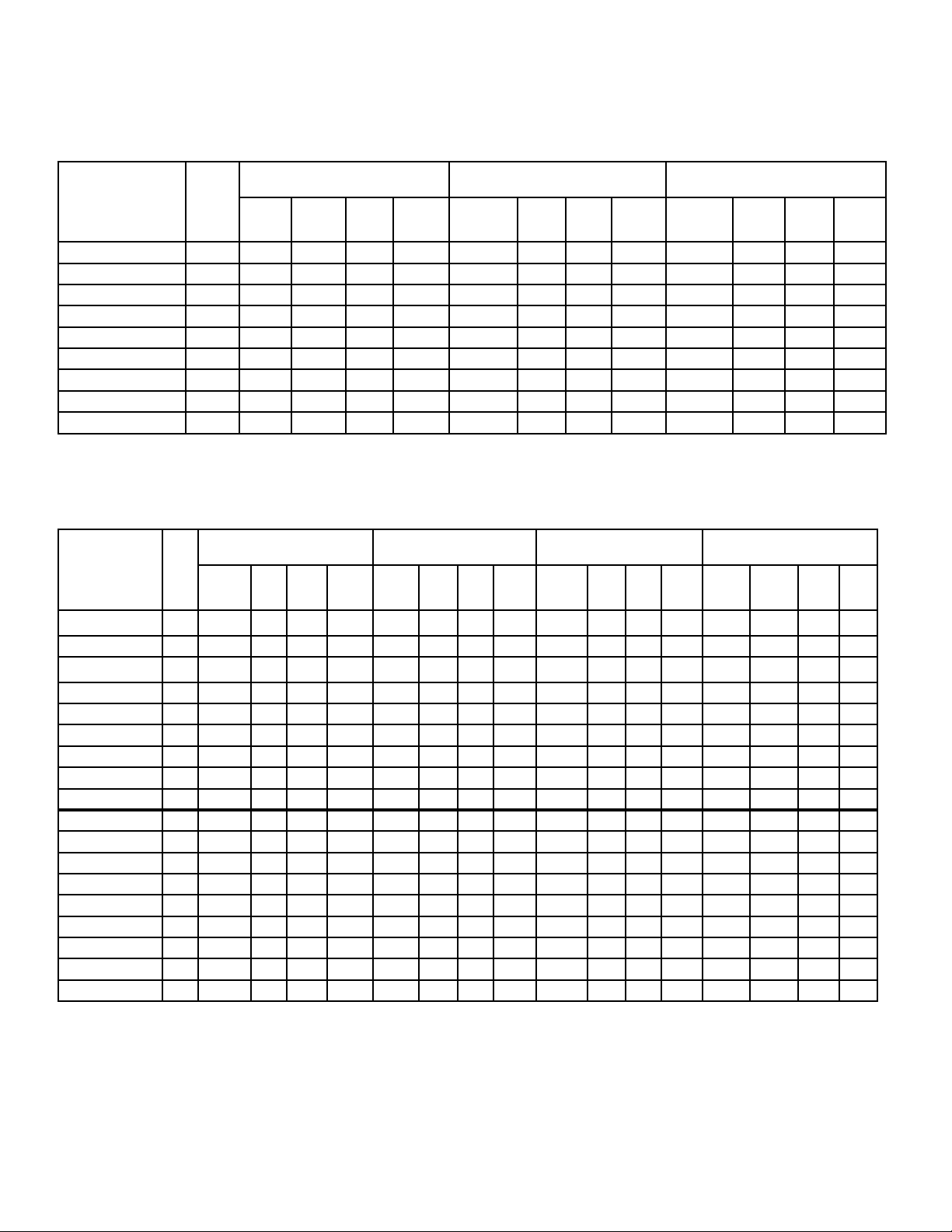
ELECTRICAL DATA
K30-KTL-PDI-3
- 4 -
06/01/12
KTL
115/1/60
AIR DEFROST
MODEL
KTL010MA-S1A 1 1.2 1.5 15 70 0.65 0.81 15 60 N/A N/A N/A N/A
KTL015MA-S1A 1 1.2 1.5 15 70 0.65 0.81 15 60 N/A N/A N/A N/A
KTL020MA-S1A 1 1.2 1.5 15 70 0.65 0.81 15 60 N/A N/A N/A N/A
KTL025MA-S1A 1 1.2 1.5 15 70 0.65 0.81 15 60 N/A N/A N/A N/A
KTL032MA-S1A 1 1.2 1.5 15 70 0.65 0.81 15 60 N/A N/A N/A N/A
KTL038MA-S1A 1 1.2 1.5 15 70 0.65 0.81 15 60 0.60 0.75 15 30
KTL060MA-S1A 2 2.4 2.7 15 140 1.30 1.46 15 120 1.20 1.35 15 60
KTL077MA-S1A 2 2.4 2.7 15 140 1.30 1.46 15 120 1.20 1.35 15 60
KTL115MA-S1A 3 3.6 3.9 15 210 1.95 2.11 15 180 1.80 1.95 15 90
No.
of
FANS
TOTAL
MOTOR
FAN MOTOR(S) -
SHADED POLE
M.C.A. M.O.P WATTS
FLA
(STANDARD)
MOTOR
TOTAL
FLA
FAN MOTOR(S) PSC (OPTIONAL)
M.C.A. M.O.P WATTS
TOTAL
MOTOR
FLA
ELECTRIC DEFROST
MODEL
KTL010ME-S1A 1 1.2 1.5 15 70 0.65 0.81 15 60 N/A N/A N/A N/A 206 1.8 2.2 15
KTL015ME-S1A 1 1.2 1.5 15 70 0.65 0.81 15 60 N/A N/A N/A N/A 530 4.6 5.8 15
KTL020ME-S1A 1 1.2 1.5 15 70 0.65 0.81 15 60 N/A N/A N/A N/A 530 4.6 5.8 15
KTL025ME-S1A 1 1.2 1.5 15 70 0.65 0.81 15 60 N/A N/A N/A N/A 530 4.6 5.8 15
KTL032ME-S1A 1 1.2 1.5 15 70 0.65 0.81 15 60 N/A N/A N/A N/A 750 6.5 8.2 15
KTL038ME-S1A 1 1.2 1.5 15 70 0.65 0.81 15 60 0.60 0.75 15 30 750 6.5 8.2 15
KTL060ME-S1A 2 2.4 2.7 15 140 1.30 1.46 15 120 1.20 1.35 15 60 1100 9.6 12.0 15
KTL077ME-S1A 2 2.4 2.7 15 140 1.30 1.46 15 120 1.20 1.35 15 60 1540 13.4 16.8 20
KTL115ME-S1A 3 3.6 3.9 15 210 1.95 2.11 15 180 1.80 1.95 15 90 2270 19.7 24.6 25
KTL009LE-S1A 1 1.2 1.5 15 70 0.65 0.81 15 60 N/A N/A N/A N/A 206 1.8 2.2 15
KTL013LE-S1A 1 1.2 1.5 15 70 0.65 0.81 15 60 N/A N/A N/A N/A 530 4.6 5.8 15
KTL017LE-S1A 1 1.2 1.5 15 70 0.65 0.81 15 60 N/A N/A N/A N/A 530 4.6 5.8 15
KTL021LE-S1A 1 1.2 1.5 15 70 0.65 0.81 15 60 N/A N/A N/A N/A 530 4.6 5.8 15
KTL028LE-S1A 1 1.2 1.5 15 70 0.65 0.81 15 60 N/A N/A N/A N/A 750 6.5 8.2 15
KTL033LE-S1A 1 1.2 1.5 15 70 0.65 0.81 15 60 0.60 0.75 15 30 750 6.5 8.2 15
KTL052LE-S1A 2 2.4 2.7 15 140 1.30 1.46 15 120 1.20 1.35 15 60 1100 9.6 12.0 15
KTL066LE-S1A 2 2.4 2.7 15 140 1.30 1.46 15 120 1.20 1.35 15 60 1540 13.4 16.8 20
KTL099LE-S1A 3 3.6 3.9 15 210 1.95 2.11 15 180 1.80 1.95 15 90 2270 19.7 24.6 25
No.
of
FANS
FAN MOTOR(S) -
SHADED POLE (STANDARD)
TOTAL
MOTOR
M.C.A. M.O.P WATTS
FLA
FAN MOTOR(S) PSC (OPTIONAL)
TOTAL
MOTOR
M.C.A. M.O.P WATTS
FLA
FAN MOTOR(S)-
EC (OPTIONAL)
TOTAL
MOTOR
M.C.A. M.O.P WATTS
FLA
TOTAL
WATTS
60Hz
FAN MOTOR(S)-
EC (OPTIONAL)
M.C.A. M.O.P WATTS
DEFROST HEATERS
TOTAL
M.C.A. M.O.P
AMPS
Page 5
ELECTRICAL DATA
K30-KTL-PDI-3
- 5 -
06/01/12
KTL
208-230/1/60
AIR DEFROST
TOTAL
MOTOR
FLA
FAN MOTOR(S) PSC (OPTIONAL)
M.C.A. M.O.P WATTS
TOTAL
MOTOR
MODEL
KTL010MA-S2A 1 0.7 0.9 15 60 0.24 0.30 15 50 N/A N/A N/A N/A
KTL015MA-S2A 1 0.7 0.9 15 60 0.24 0.30 15 50 N/A N/A N/A N/A
KTL020MA-S2A 1 0.7 0.9 15 60 0.24 0.30 15 50 N/A N/A N/A N/A
KTL025MA-S2A 1 0.7 0.9 15 60 0.24 0.30 15 50 N/A N/A N/A N/A
KTL032MA-S2A 1 0.7 0.9 15 60 0.24 0.30 15 50 N/A N/A N/A N/A
KTL038MA-S2A 1 0.7 0.9 15 60 0.24 0.30 15 50 0.30 0.40 15 30
KTL060MA-S2A 2 1.4 1.6 15 120 0.48 0.54 15 100 0.60 0.70 15 60
KTL077MA-S2A 2 1.4 1.6 15 120 0.48 0.54 15 100 0.60 0.70 15 60
KTL115MA-S2A 3 2.1 2.3 15 180 0.72 0.78 15 150 0.90 1.00 15 90
No.
of
FANS
TOTAL
MOTOR
FAN MOTOR(S) -
SHADED POLE
M.C.A. M.O.P WATTS
FLA
(STANDARD)
FAN MOTOR(S)-
EC (OPTIONAL)
FLA
ELECTRIC DEFROST
60Hz
M.C.A. M.O.P WATTS
FAN MOTOR(S) -
MODEL
KTL010ME-S2A 1 0.7 0.9 15 60 0.24 0.30 15 50 - - - - 206 0.9 1.1 15
KTL015ME-S2A 1 0.7 0.9 15 60 0.24 0.30 15 50 - - - - 530 2.3 2.9 15
KTL020ME-S2A 1 0.7 0.9 15 60 0.24 0.30 15 50 - - - - 530 2.3 2.9 15
KTL025ME-S2A 1 0.7 0.9 15 60 0.24 0.30 15 50 - - - - 530 2.3 2.9 15
KTL032ME-S2A 1 0.7 0.9 15 60 0.24 0.30 15 50 - - - - 750 3.3 4.1 15
KTL038ME-S2A 1 0.7 0.9 15 60 0.24 0.30 15 50 0.30 0.40 15 30 750 3.3 4.1 15
KTL060ME-S2A 2 1.4 1.6 15 120 0.48 0.54 15 100 0.60 0.70 15 60 1100 4.8 6.0 15
KTL077ME-S2A 2 1.4 1.6 15 120 0.48 0.54 15 100 0.60 0.70 15 60 1540 6.7 8.4 15
KTL115ME-S2A 3 2.1 2.3 15 180 0.72 0.78 15 150 0.90 1.00 15 90 2270 9.9 12.4 15
KTL009LE-S2A 1 0.7 0.9 15 60 0.24 0.30 15 50 - - - - 206 0.9 1.1 15
KTL013LE-S2A 1 0.7 0.9 15 60 0.24 0.30 15 50 - - - - 530 2.3 2.9 15
KTL017LE-S2A 1 0.7 0.9 15 60 0.24 0.30 15 50 - - - - 530 2.3 2.9 15
KTL021LE-S2A 1 0.7 0.9 15 60 0.24 0.30 15 50 - - - - 530 2.3 2.9 15
KTL028LE-S2A 1 0.7 0.9 15 60 0.24 0.30 15 50 - - - - 750 3.3 4.1 15
KTL033LE-S2A 1 0.7 0.9 15 60 0.24 0.30 15 50 0.30 0.40 15 30 750 3.3 4.1 15
KTL052LE-S2A 2 1.4 1.6 15 120 0.48 0.54 15 100 0.60 0.70 15 60 1100 4.8 6.0 15
KTL066LE-S2A 2 1.4 1.6 15 120 0.48 0.54 15 100 0.60 0.70 15 60 1540 6.7 8.4 15
KTL099LE-S2A 3 2.1 2.3 15 180 0.72 0.78 15 150 0.90 1.00 15 90 2270 9.9 12.4 15
No. of
FANS
SHADED POLE(STANDARD)
TOTAL
MOTOR
M.C.A. M.O.P WATTS
FLA
FAN MOTOR(S) PSC (OPTIONAL)
TOTAL
MOTOR
M.C.A. M.O.P WATTS
FLA
FAN MOTOR(S)-
EC (OPTIONAL)
TOTAL
MOTOR
M.C.A. M.O.P WATTS
FLA
DEFROST HEATERS
TOTAL
WATTS
TOTAL
AMPS
M.C.A. M.O.P
Page 6

KTL
K30-KTL-PDI-3
- 6 -
06/01/12
WIRING DIAGRAM
AIR DEFROST - ALL VOLTAGES
60Hz
GND
WITH DEFROST TIME CLOCK
DEFROST CLOCK
PARAGON # 8145
OR EQUIVALENT
TM
4NX
132
PUMP DOWN
SWITCH
(IF USED)
SPACE
THERMOSTAT
NOTE #4
REFER TO EVAPORATOR
NAMEPLATE FOR ELECTRICAL
REQUIREMENTS
L2(N)
L1
GND
FUSE OR
CIRCUIT
BREAKER
NOTE #3
OMIT 2ND
FUSE
IF(N)
TO MULTIPLE EVAPS
F
4
(IF APPLIC)
LIQUID LINE
SOLENOID VALVE
NOTE #4
WITHOUT DEFROST TIME CLOCK
REFER TO EVAPORATOR
NAMEPLATE FOR ELECTRICAL
REQUIREMENTS
L2(N)
L1
GND
FUSE OR
CIRCUIT
BREAKER
NOTE #3
OMIT
2ND FUSE
IF(N)
F
4
THERMOSTAT
TO MULTIPLE
EVAPORATORS (IF APPLIC)
SPACE
NOTE #4
SOLENOID VALVE
LIQUID LINE
NOTE #4
GND.
NOTES
1). USE COPPER CONDUCTORS ONLY
2). USE 75°C WIRE (OR HIGHER)
3). OVERCURRENT PROTECTION FOR
EVAPORATOR FAN MOTORS AND DEFROST
HEATERS MUST NOT EXCEED MAXIMUM
VALUE SHOWN ON EVAPORATOR NAMEPLATE.
4). MAY BE FACTORY INSTALLED-MOUNTED AND
WIRED ON EVAPORATOR .
1-TL AD 03/08
N.C.
EVAPORATOR
GND.
4
F
TERMINAL BOARD
(SUPPLIED ON MULTIPLE
FAN MODELS ONLY)
4
F
TERMINAL BOARD
(SUPPLIED ON MULTIPLE
FAN MODELS ONLY)
FAN MOTOR
POWER
PLUGS
REFER TO
FAN
MTR
FAN
MTR
EVAPORATOR
FAN
MTR
DATA PLATE
FAN
MTR
FAN
MTR
FOR MOTOR
QUANTITY
TERMINALS
-COMPONENT TERMINAL
-TERMINAL BLOCK TERMINAL
CONDUCTORS/WIRING
FACTORY WIRING
WIRING BY OTHERS
OPTIONAL FACTORY OR
BY OTHERS
ALL FIELD WIRING MUST BE DONE IN
COMPLIANCE WITH ALL APPLICABLE LOCAL
AND NATIONAL CODES.
N.C.
EVAPORATOR
FAN MOTOR
POWER
PLUGS
REFER TO
EVAPORATOR
FAN
MTR
DATA PLATE
FOR MOTOR
QUANTITY
Page 7

KTL
FAN
MTR
FAN
MTR
FAN
MTR
DATA PLATE FOR
MOTOR QUANTITY
EVAPORATOR
REFER TO
EVAPORATOR
FAN MOTOR
POWER PLUGS
RD
DEFROST TERMINATION
FD-FAN DELAY
DT-DEFROST TERM
& FAN DELAY
(10.0A MAX.)
CONTROL
FD
BK
FAN MOTOR
POWER PLUGS
REFER TO
DATA PLATE FOR
MOTOR QUANTITY
EVAPORATOR
MTRMTRMTR
FANFAN FAN
(10.0A MAX.)
DT-DEFROST TERM
FD-FAN DELAY
& FAN DELAY
CONTROL
DEFROST TERMINATION
FD
BK
EVAPORATOR
PARAGON # 8145
MUST BE MADE
EVAP FIELD MODIFICATION
WARNING
SEE NOTE:
SPACE
GND.
F
4
DT
BN
C
X
3
N
H1
H3H2
ORANGE JUMPER
THERMOSTAT
NOTE #4
SWITCH
(IF USED)
PUMP DOWN
NOTE #4
SOL VALVE
1
N.C.
LIQUID LINE
BREAKER
(IF USED)
COMPR INTERLOCK
12
N
NAMEPLATE FOR ELECTRICAL
REFER TO EVAPORATOR
GND
REQUIREMENTS
3
4
TM
X
FUSE OR
CIRCUIT
PARAGON # 8145
DEFROST CLOCK
OR EQUIVALENT
15A
N
L1
N.C.
LIQUID LINE
SOL VALVE
NOTE #4
GND.
3
N
X
4
F
DT
BN
RD
C
FROM H2 TO N
REMOVE ORANGE JUMPER
(IF USED)
SWITCH
PUMP DOWN
NOTE #4
H2
H3
H1
SPACE
THERMOSTAT
(IF USED)
COMPR INTERLOCK
OR EQUIVALENT
1
CIRCUIT
4
2
3
X
N
NOTE #3
BREAKER
TM
FUSE OR
DEFROST HEATER
L1
C
T1
CONTACTOR
CIRCUIT
BREAKER
NOTE #3
N
GND
L1
FUSE OR
USING MAXIMUM 15A HEATER OVERCURRENT PROTECTION
FOR ALL MODELS WITHOUT DEFROST HEATER CONTACTOR
FOR ALL MODELS USING DEFROST HEATER CONTACTOR
REFER TO EVAPORATOR
DEFROST CLOCK
REQUIREMENTS
NAMEPLATE FOR ELECTRICAL
FAN MODELS ONLY)
(SUPPLIED ON MULTIPLE
TERMINAL BOARD
BK
BK
DEFROST HEATERS
BOTTOM
BK
BOTTOM
L.H. COIL
BK
R.H. COIL
ORANGE
JUMPER
DEFROST HEATERS
L.H. COIL
BOTTOM
BK
R.H. COIL
BOTTOM
BK
BK
BK
ORANGE
JUMPER
T2
L2
ORANGE JUMPER
1
SEE NOTE:
TERMINAL BOARD
(SUPPLIED ON MULTIPLE
FAN MODELS ONLY)
DEFROST HEATERS MUST NOT EXCEED
4.) MAY BE FACTORY INSTALLED-MOUNTED
MAXIMUM VALUE SHOWN ON
EVAPORATOR NAMEPLATE.
EVAPORATOR FAN MOTORS AND
AND WIRED ON EVAPORATOR
1). USE COPPER CONDUCTORS ONLY
3). OVERCURRENT PROTECTION FOR
2). USE 75°C WIRE (OR HIGHER)
NOTES
FACTORY WIRING
OPTIONAL FACTORY
WIRING BY OTHERS
OR BY OTHERS
ALL FIELD WIRING MUST BE DONE IN
COMPLIANCE WITH ALL APPLICABLE LOCAL
AND NATIONAL CODES.
TERMINALS
-TERMINAL BLOCK TERMINAL
-COMPONENT TERMINAL
CONDUCTORS/WIRING
2-TL ED1 03/08
(IF APPLIC.)
K30-KTL-PDI-3
- 7 -
06/01/12
WIRING DIAGRAM
ELECTRIC DEFROST - 115V
60Hz
Page 8

KTL
4.) MAY BE FACTORY INSTALLED-MOUNTED
AND WIRED ON EVAPORATOR
3-TL ED2 03/08
MOTOR QUANTITY
1). USE COPPER CONDUCTORS ONLY
3). OVERCURRENT PROTECTION FOR
2). USE 75°C WIRE (OR HIGHER)
MAXIMUM VALUE SHOWN ON
EVAPORATOR NAMEPLATE.
DEFROST HEATERS MUST NOT EXCEED
EVAPORATOR FAN MOTORS AND
NOTES
MTR
FAN
(10.0A MAX.)
MTR
FAN
MTR
FAN
DT-DEFROST TERM
FD-FAN DELAY
GND.
DT
DEFROST TERMINATION
BK
& FAN DELAY
C
FD
CONTROL
X
4
F
BN
RD
EVAPORATOR
DATA PLATE FOR
REFER TO
EVAPORATOR
POWER PLUGS
FAN MOTOR
FAN MODELS ONLY)
JUMPER
TERMINAL BOARD
ORANGE
(SUPPLIED ON MULTIPLE
3
N
H1
H2
H3
(IF USED)
COMPR INTERLOCK
NOTE #4
THERMOSTAT
SPACE
SWITCH
(IF USED)
PUMP DOWN
ORANGE JUMPER
SOL VALVE
NOTE #4
LIQUID LINE
N.C.
OR BY OTHERS
ALL FIELD WIRING MUST BE DONE IN
COMPLIANCE WITH ALL APPLICABLE LOCAL
AND NATIONAL CODES.
FANFANFAN
EVAPORATOR
-TERMINAL BLOCK TERMINAL
-COMPONENT TERMINAL
OPTIONAL FACTORY
WIRING BY OTHERS
FACTORY WIRING
CONDUCTORS/WIRING
TERMINALS
FROM H2 TO N
REMOVE ORANGE JUMPER
SEE NOTE:
DATA PLATE FOR
MOTOR QUANTITY
WARNING
EVAP FIELD MODIFICATION
MUST BE MADE
MTRMTR
1
MTR
FAN MOTOR
TERMINAL BOARD
(SUPPLIED ON MULTIPLE
FAN MODELS ONLY)
REFER TO
POWER PLUGS
& FAN DELAY
FD-FAN DELAY
DT-DEFROST TERM
(10.0A MAX.)
CONTROL
X
DEFROST TERMINATION
GND.
BK
F
4
DT
C
FD
N
BN
RD
3
EVAPORATOR
H3
JUMPER
ORANGE
H1
H2
NOTE #4
LIQUID LINE
SOL VALVE
SEE NOTE:
ORANGE JUMPER
N.C.
NOTE #4
(IF USED)
PUMP DOWN
1
SWITCH
(IF USED)
THERMOSTAT
SPACE
COMPR INTERLOCK
CONTACTOR
DEFROST HEATER
C
T1
L1
T2
L2
FOR ALL MODELS WITHOUT DEFROST HEATER CONTACTOR
REQUIREMENTS
REFER TO EVAPORATOR
NAMEPLATE FOR ELECTRICAL
GND
USING MAXIMUM 15A HEATER OVERCURRENT PROTECTION
PARAGON # 8145
DEFROST CLOCK
OR EQUIVALENT
3
1
X4
TM
N
2
FUSE OR
CIRCUIT
15A
BREAKER
L1
L2
FOR ALL MODELS USING DEFROST HEATER CONTACTOR
PARAGON # 8145
3
1X42
N
OR EQUIVALENT
DEFROST CLOCK
TM
CIRCUIT
BREAKER
FUSE OR
NOTE #3
FUSE OR
CIRCUIT
BREAKER
NOTE #3
L1
GND
L2
DEFROST HEATERS
L.H. COIL
R.H. COIL
BOTTOM
BOTTOM
BK
BK
BK
BK
DEFROST HEATERS
L.H. COIL
R.H. COIL
BOTTOM
BOTTOM
BK
BK
BK
BK
(IF APPLIC.)
REQUIREMENTS
REFER TO EVAPORATOR
NAMEPLATE FOR ELECTRICAL
K30-KTL-PDI-3
- 8 -
06/01/12
WIRING DIAGRAM
ELECTRIC DEFROST - 230V
60Hz
Page 9

BOTTOM VIEW
Connection
CONNECTION END VIEW
TXV
Connection
AIR
OUT
AIR IN
with electric defrost heaters
splice box and defrost control
NOTE: Dimensional views shown
Suction
OUT
AIR
mounted.
7/8 (22 mm) dia.
2 each side
9/16 (14 mm) dia.
2 each side
1/2 (12 mm) dia.
aluminum drain.
2 connection end
7/8 (22 mm) dia.
knockouts
knockouts
knockouts
SIDE VIEW
PIPING CONNECTION
1-3/8"
(35 mm)
3"
(76 mm)
9/16"
(14 mm)
Splice box.
electric defrost models
Defrost control
4 Mounting holes
7/32 (6 mm) dia.
E
D
B
A
C
KTL
K30-KTL-PDI-3
- 9 -
06/01/12
DIMENSIONAL DATA - 1 FAN
Inches (mm)
60Hz
MODEL
KTL 010M* 3/8 1/2” Flare 18 7/8 479 4 1/2 114 14 1/8 359 17 3/4 451 9 3/4 248 11.6 5.3
KTL 015M* 3/8 1/2” Flare 18 7/8 479 4 1/2 114 14 1/8 359 17 3/4 451 9 3/4 248 12.6 5.7
KTL 020M* 3/8 1/2” Flare 18 7/8 479 5 1/2 140 14 1/8 359 17 3/4 451 9 3/4 248 13.7 6.2
KTL 025M* 3/8 1/2” Flare 18 7/8 479 5 1/2 140 14 1/8 359 17 3/4 451 9 3/4 248 14.7 6.7
KTL 032M* 3/8 1/2” ODS 21 7/8 556 5 1/2 140 19 1/8 486 20 3/4 527 14 3/4 375 18.9 8.6
KTL 038M* 3/8 1/2” ODS 21 7/8 556 5 1/2 140 19 1/8 486 20 3/4 527 14 3/4 375 20.0 9.1
KTL 009LE 3/8 1/2” Flare 18 7/8 479 4 1/2 114 14 1/8 359 17 3/4 451 9 3/4 248 11.6 5.3
KTL 013LE 3/8 1/2” Flare 18 7/8 479 4 1/2 114 14 1/8 359 17 3/4 451 9 3/4 248 12.6 5.7
KTL 017LE 3/8 1/2” ODS 18 7/8 479 5 1/2 140 14 1/8 359 17 3/4 451 9 3/4 248 13.7 6.2
KTL 021LE 3/8 1/2” ODS 18 7/8 479 5 1/2 140 14 1/8 359 17 3/4 451 9 3/4 248 14.7 6.7
KTL 028LE 1/2 1/2” ODS 21 7/8 556 5 1/2 140 19 1/8 486 20 3/4 527 14 3/4 375 18.9 8.6
KTL 033LE 1/2 1/2” ODS 21 7/8 556 5 1/2 140 19 1/8 486 20 3/4 527 14 3/4 375 20.0 9.1
* - A (AIR DEFROST) OR E (ELECTRIC DEFROST)
Suc. Conn. TXV A B C D E
(ID) Sweat Inlet Size Inches mm Inches mm Inches mm Inches mm Inches mm Lbs. Kgs
APPROX.
WEIGHT
Page 10

compartment
Electrical
OUT
AIR
AIR
PIPING CONNECTION
END VIEW
AIR IN
2 each side
knockouts
7/8 (22 mm) dia
knockouts
9/16 (14 mm) dia
2 each side
2). Electrical connection end is
opposite the piping end on
NOTES: 1). Electric defrost views shown.
Air defrost models have identical
BOTTOM VIEW
AIR
SIDE VIEW
AIR
OUT
1-1/8 (28 mm) dia
knockouts
1 each side
1" FPT. Aluminum
drain fitting.
dimensioning.
multiple fan models.
1 each side
knockouts
7/8 (22 mm) dia
TXV Connection 1/2"(13) ODS.
33
5/16 (9 mm)
Mounting holes.
22-1/4
(565)
ED F
23-5/8
(600)
C
7-5/8
(194)
23-3/4 (603)
K30-KTL-PDI-3
- 10 -
06/01/12
KTL
DIMENSIONAL DATA - 2 & 3 FAN
Inches (mm)
60Hz
MODEL
KTL 060M 1/2 1/2” ODS 42 3/4 1086 4 holes @ 8” 203 7 11/16 195 10 15/16 278 37.8 17.1
KTL 077M 5/8 1/2” ODS 42 3/4 1086 4 holes @ 8” 203 7 11/16 195 10 15/16 278 39.9 18.1
KTL 115M 5/8 1/2” ODS 59 1/2 1511 6 holes @ 8” 203 8 203 11 7/16 291 59.9 27.2
KTL 052LE 5/8 1/2” ODS 42 3/4 1086 4 holes @ 8” 203 7 11/16 195 10 15/16 278 37.8 17.1
KTL 066LE 5/8 1/2” ODS 42 3/4 1086 4 holes @ 8” 203 7 11/16 195 10 15/16 278 39.9 18.1
KTL 099LE 7/8 1/2” ODS 59 1/2 1511 6 holes @ 8” 203 8 203 11 7/16 291 59.9 27.2
Suc. Conn. TXV C D E F APPROX. WEIGHT
(ID) Sweat Inlet Size Inches mm Inches mm Inches mm Inches mm Lbs. Kgs
Page 11

NOZZLE SELECTIONS
K30-KTL-PDI-3
- 11 -
06/01/12
KTL
Nozzle Selections (Factory installed)
For all applications and refrigerants
Model Nozzle
KTL010MA/ME NA
KTL015MA/ME NA
KTL020MA/ME NA
KTL025MA/ME NA
KTL032MA/ME L-1/4
KTL038MA/ME L-1/3
KTL060MA/ME L-1/2
KTL077MA/ME L-3/4
KTL115MA/ME L-1
MEDIUM TEMP - EXPANSION VALVE SELECTION
SPORLAN
MODEL TD
KTL010M
KTL015M
KTL020M
KTL025M
KTL032M
KTL038M
KTL060M
KTL077M
KTL115M
For medium temp. R-507, refrigerant designation changes from ‘S’ to ‘P’.
CAPACITY @
25°F SST
10 950
15 1,425
10 1,450
15 2,175
10 2,000 GS-1/8-C
15 3,000 GS-1/6-C
10 2,500
15 3,750 GV-1/3-C
10 3,200 EGSE-1/4-C EGVE-1/3-C
15 4,800 EGSE-1/2-C EGVE-1/2-C
10 3,800 EGSE-1/4-C EGVE-1/3-C
15 5,700 EGSE-1/2-C EGVE-1/2-C
10 6,000 EGSE-1/2-C
15 9,000 EGSE-1-C
10 7,700 EGSE-1/2-C EGVE-3/4-C
15 11,550 EGSE-1-C EGVE-1-C
10 11,500 EGSE-1-C EGVE-1-C
15 17,250 EGSE-1 1/2-C EGVE-1 1/2-C
R404A
R507
GS-1/8-C GV-1/5-C
GS-1/8-C GV-1/5-C
GS-1/6-C
R22
R407C
GV-1/5-C
GV-1/5-C
EGVE-3/4-C
ALCO
MODEL TD
KTL010M
KTL015M
KTL020M
KTL025M
KTL032M
KTL038M
KTL060M
KTL077M
KTL115M
10 950
15 1,425
10 1,450
15 2,175
10 2,000 HF-1/8-SC
15 3,000 HF-1/4-SC
10 2,500
15 3,750
10 3,200 HFESC-1/4-SC HFESC-1/4-HC
15 4,800 HFESC-1/2-SC HFESC-1/2-HC
10 3,800 HFESC-1/4-SC
15 5,700 HFESC-1/2-SC
10 6,000 HFESC-1/2-SC HFESC-1/2-HC
15 9,000 HFESC-1-SC HFESC-1-HC
10 7,700 HFESC-1/2-SC
15 11,550 HFESC-1-SC
10 11,500 HFESC-1-SC HFESC-1-HC
15 17,250 HFESC-1 1/4-SC HFESC-1 1/2-HC
CAPACITY @
25°F SST
R404A
R507
HF-1/8-SC HF-1/4-HC
HF-1/8-SC HF-1/4-HC
HF-1/4-SC HF-1/4-HC
R22
R407C
HF-1/4-HC
HFESC-1/2-HC
HFESC-1-HC
DANFOSS
MODEL TD
KTL010M
KTL015M
KTL020M
KTL025M
KTL032M
KTL038M
KTL060M
KTL077M
KTL115M
Model Nozzle
KTL009LE NA
KTL013LE NA
KTL017LE L-1/4
KTL021LE L-1/3
KTL028LE L-1/2
KTL033LE L-1/2
KTL052LE L-1
KTL066LE L-1
KTL099LE L-1 1/2
CAPACITY @
25°F SST
10 950 TUA-R404A-0-N
15 1,425 TUA-R404A-1-N
10 1,450 TUA-R404A-1-N TUA-R22-0-N
15 2,175 TUA-R404A-2-N TUA-R22-1-N
10 2,000 TUA-R404A-2-N TUA-R22-1-N
15 3,000 TUAE-R404A-3-N TUAE-R22-2-N
10 2,500 TUA-R404A-2-N TUA-R22-1-N
15 3,750 TUAE-R404A-3-N TUAE-R22-2-N
10 3,200 TUAE-R404A-3-N TUAE-R22-2-N
15 4,800 TUAE-R404A-4-N TUAE-R22-3-N
10 3,800 TUAE-R404A-3-N TUAE-R22-3-N
15 5,700 TUAE-R404A-4-N TUAE-R22-4-N
10 6,000 TUAE-R404A-5-N TUAE-R22-4-N
15 9,000 TUAE-R404A-6-N TUAE-R22-5-N
10 7,700 TUAE-R404A-5-N TUAE-R22-5-N
15 11,550 TUAE-R404A-6-N TUAE-R22-6-N
10 11,500 TUAE-R404A-6-N TUAE-R22-6-N
15 17,250 TUAE-R404A-8-N TUAE-R22-7-N
R404A
R507
60Hz
R22
R407C
TUA-R22-0-N
ALL TXV Selections based on 90-100°F liquid.
Page 12

LOW TEMP
K30-KTL-PDI-3
- 12 -
06/01/12
R404A
EXPANSION VALVE SELECTIONS
R507
60HzKTL
SPORLAN
R404A
R507
0 910 GS-1/8-C 1,340 GS-1/8-C 1,820 EGSE-1/8-C 2,250 EGSE-1/6-C 3,000 EGSE-1/4-C
EVAP
TEMP.
EVAP
TEMP.
°F
For medium temp. R-507, refrigerant designation changes from ‘S’ to ‘P’.
For R404A/R507 valves operating below 0F, the pressure limiting charge ‘ZP’ may be substituted for the ‘Z’ charge.
-10 880
-15 870 1,280 1,730 2,140 2,860
°F
-20 850 1,250 1,700 2,100 2,800
0 3,530 EGSE-1/4-C 5,560 EGSE-1/2-C 7,060 EGSE-1/2-C 10,590 EGSE-1-C
-10 3,430
-20 3,300 5,200 6,600 9,900
KTL009L KTL013L KTL017L KTL021L KTL028L
BTUH VALVE # BTUH VALVE # BTUH VALVE # BTUH VALVE # BTUH VALVE #
1,300
GS-1/8-Z
KTL033L KTL052L KTL066L KTL099L
BTUH VALVE # BTUH VALVE BTUH VALVE # BTUH VALVE #
5,410
EGSE-1/4-Z
GS-1/8-Z
EGSE-1/2-Z
1,770
6,860
EGSE-1/6-Z
EGSE-1-Z
2,180
10,300
EGSE-1/6-Z
2,910
EGSE-1-Z-15 3,370 5,300 6,730 10,100
ALCO
R404A
R507
EVAP
TEMP.
°F
EVAP
TEMP.
°F
0 910 HF-1/8-SC 1,340 HF-1/8-SC 1,820 HFESC-1/8-SC 2,250 HFESC-1/8-SC 3,000 HFESC-1/4-SC
-10 880
-15 870 1,280 1,730 2,140 2,860
-20 850 1,250 1,700 2,100 2,800
0 3,530 HFESC-1/4-SC 5,560 HFESC-1/2-SC 7,060 HFESC-1/2-SC 10,590 HFESC-1-SC
-10 3,430
-20 3,300 5,200 6,600 9,900
KTL009L KTL013L KTL017L KTL021L KTL028L
BTUH VALVE # BTUH VALVE # BTUH VALVE # BTUH VALVE # BTUH VALVE #
1,300
HF-1/8-SW45
KTL033L KTL052L KTL066L KTL099L
BTUH VALVE # BTUH VALVE # BTUH VALVE # BTUH VALVE #
5,410
HFESC-1/2-SW45
HF-1/8-SW45
HFESC-1/2-SW45
1,770
6,860
HFESC-1/4-SW45
HFESC-1-SW45
2,180
10,300
HFESC-1/4-SW45
2,910
HFESC-1 1/4-SW45-15 3,370 5,300 6,730 10,100
EGSE-1/4-Z
HFESC-1/4-SW45
For medium temp. R-507, refrigerant designation changes from ‘S’ to ‘P’.
DANFOSS
EVAP
TEMP.
EVAP
TEMP.
°F
All TXV Selections based on 90-100°F liquid.
R404A
R507
0 910 TUA-R404A-0-N 1,340 TUA-R404A-1-N 1,820 TUAE-R404A-2-N 2,250 TUA-R404A-3-N 3,000 TUAE-R404A-4-N
-10 880
-15 870 1,280 1,730 2,140 2,860
°F
-20 850 1,250 1,700 2,100 2,800
0 3,530 TUAE-R404A-4-N 5,560 TUAE-R404A-5-N 7,060 TUAE-R404A-6-N 10,590 TUAE-R404A-7-N
-10 3,430
-20 3,300 5,200 6,600 9,900
KTL009L KTL013L KTL017L KTL021L KTL028L
BTUH VALVE # BTUH VALVE # BTUH VALVE # BTUH VALVE # BTUH VALVE #
1,300
TUA-R404A-0-NM
KTL033L KTL052L KTL066L KTL099L
BTUH VALVE # BTUH VALVE # BTUH VALVE # BTUH VALVE #
TUAE-R404A-5-NM
TUA-R404A-2-NM
5,410
TUAE-R404A-6-NM
1,770
6,860
TUAE-R404A-3-NM
TUAE-R404A-7-NM
2,180
TUAE-R404A-4-NM
10,300
TUAE-R404A-8-NM-15 3,370 5,300 6,730 10,100
2,910
TUAE-R404A-5-NM
Page 13

KTL
K30-KTL-PDI-3
- 13 -
06/01/12
INSTALLATION INSTRUCTIONS
60Hz
INSPECTION
Careful inspection of all parts when received for
loss or damage in transit is very important -
Remember, you, the consignee, must make any
claim necessary against the transportation company.
Shipping damage or missing parts, when discovered
at the outset, will prevent later unnecessary and
costly delays.
Electrical characteristics should also be checked at
this time to ensure that they are as ordered.
APPLICATION
Two-Way evaporators are designed for use in
coolers and freezers such as reach in boxes, dis-
play cases, back bars, walk-in rooms and any other
cooler applications where a low velocity, uniform air
ow is required. The compact and low height unit
provides maximum useable product storage space.
At room temperatures above 34 °F (1.1
evaporating temperatures no lower than 27 °F (-2.8
°C) the air owing through the coil will accomplish
the defrost (Air Defrost).
At room temperatures 34
positive defrosting is required (Electric defrost).
These will require the use of :
1. Time Clock (to initiate and terminate the defrost
cycle),
2. Defrost termination thermostat (to prevent
unnecessary prolonged heating and steaming of the
coil once all the frost and ice has melted). And if a
freezer,
3. Fan delay thermostat (to prevent evaporator fans
starting up right away and blowing water on to the
fan blades, guards and oor).
This evaporator coil must not be exposed to any
abnormal environments (acidic or caustic) that can
result in coil corrosion and leaks. Consult factory
for optional baked on phenolic protective coatings.
These evaporators are for use primarily on R22 and
R404A refrigerants and their approved alternatives /
replacements.
INSTALLATION
The installation and start up of evaporators should
only be performed by qualied refrigeration
mechanics. This equipment should be installed in
accordance with all applicable codes, ordinances,
and local by-laws.
o
F and below (to -10
o
C) and
o
F)
LOCATION
The evaporator is designed to be mounted to the
ceiling of the box or cabinet. Refrigeration piping and
electrical connections are routed to the rear sides
(through the knock-outs). The unit must be mounted
to a level ceiling to ensure complete drainage from
the condensate pan to the drain tting. Refer to the
dimensional drawings for the drain tting and
mounting location details.
On freezer applications it is important that warm,
humid inltrated air is not drawn directly towards
the evaporator. Keeping the evaporator away
from the door, using strip curtains, and using door
switches to lock out and de-energize the liquid solenoid valve are all effective methods to minimize any
unnecessary frost build -up of the fan guard. (Air
enters the fan and discharges out each side of the
coil).
TXV SELECTION (thermostatic expansion valve)
For normal operating conditions refer to the TXV
selection chart. When selecting valves ensure they
are sized to meet the capacity at the actual evaporating temperature, liquid temperature and operating
TD of the system . All these conditions can greatly
affect the size and selection. Consult the factory or
valve manufacturer for assistance. All models that
use a distributor (larger models) must use a nozzle.
Smaller models do not have distributors or nozzles.
The TXV superheat setting should NOT be initially
adjusted . After the room has reached or is close to
the required operating temperature the TXV super-
heat should then be checked and only adjusted if
necessary. Refer to Section on SYSTEM CHECK.
To avoid overheating the valve or distributor
wrap a wet cloth around the valve diaphragm
and body.
MOUNTING
Mounting brackets with 7/32 - 5/16” diameter holes
are provided for ush mounting to the ceiling.
Ensure the evaporator is located correctly with
the air owing in the two desired directions. Avoid
discharging the air directly on to glass doors or door
openings.
After mounting the coil check the slope of the
drain pan with a level. If the ceiling is not level the
drain pan slope may not be correct which can result
in defrosting (ice-up) problems.
Page 14

INSTALLATION INSTRUCTIONS (CONT’D)
K30-KTL-PDI-3
- 14 -
06/01/12
KTL
DRAIN LINE
The drain line should be run from the drain
connection, sloping at least 4” vertical drop for
every foot of horizontal distance . A trap outside
the room will allow proper draining throughout the
line. Connection should be made to proper drainage
facilities that comply with local codes and regulations.
In freezers, to prevent drain line freeze up prob-
lems, the line must be heated and insulated. A heat
input of 20 W per foot in a 0 °F room and 30 W
per foot in a -20 °F room is usually satisfactory.
Once the line has been completed , double check
the slope in the drain pan to ensure proper drainage
(prevention of ice build-up on pan).
PIPING
Refrigerant line sizes are important and are not
necessarily the same size as the connections at the
condensing unit or evaporator. If in doubt refer to
a recognized source. (Manufacturer’s Engineering
Manual, Ashrae Manuals, etc.)
WIRING
Wire system in accordance with local codes and
regulations. A 36” cord is provided for single fan air
defrost models (AD). Multiple fans have a junction
terminal box for conduit connections.
60Hz
When fan delay thermostats are installed the fans
may not start up until the coil temperature
reaches approximately 26 °F. On initial start up it may
be necessary to bypass (jumper) this control
temporarily until the coil is cold enough.
SYSTEM CHECK
Before Start Up:
1. Ensure wiring is in accordance with codes.
2. Refrigerant lines are properly sized and routed.
3. Thorough leak check, evacuation and dehydration
has been performed.
4. Drain line has been checked for free ow.
After Start Up:
1. Fan has been checked for correct air ow and no
obstructions.
2. Expansion valve superheat has been checked for
proper operation. (Superheat of the coil should be
around 5 to 6 °F for a 10 °F TD.)
MAINTENANCE
The unit should be periodically inspected for any dirt
or build up on the n surface and cleaned if
necessary with a soft whisk or brush.
The fan motor is permanently lubricated and should
not require service.
GENERIC SERVICE PARTS LIST
MODEL NUMBER
MEDIUM
TEMP
KTL010M KTL009L 1043293 1088581 1088582 1043870-001 1088583 1088584 1043870-002 N/A N/A N/A
KTL015M KTL013L 1043293 1088581 1088582 1043870-002 1088583 1088584 1043870-002 N/A N/A N/A
KTL020M KTL017L 1043293 1088581 1088582 1043870-003 1088583 1088584 1043870-003 N/A N/A N/A
KTL025M KTL021L 1043293 1088581 1088582 1043870-004 1088583 1088584 1043870-004 N/A N/A N/A
KTL032M KTL028L 1043294 1088581 1088582 1043870-005 1088583 1088584 1043870-005 N/A N/A N/A
KTL038M KTL033L 1043294 1088581 1088582 1043870-005 1088583 1088584 1043870-005 1091721 1091722 1043870-005
KTL060M KTL052L 1043294 1088581 1088582 1043870-005 1088583 1088584 1043870-005 1091721 1091722 1043870-005
KTL077M KTL066L 1043294 1088581 1088582 1043870-005 1088583 1088584 1043870-005 1091721 1091722 1043870-005
KTL115M KTL099L 1043294 1088581 1088582 1043870-006 1088583 1088584 1043870-006 1091721 1091722 1043870-006
MEDIUM TEMP LOW TEMP AIR DEFROST
KTL010M KTL009L 1070468-001 1043868-001 N/A N/A 1043725
KTL015M KTL013L 1069861-001 1043868-001 N/A N/A 1043725
KTL020M KTL017L 1069861-001 1043868-001 N/A N/A 1043725
KTL025M KTL021L 1069861-001 1043868-001 N/A N/A 1043725
KTL032M KTL028L 1069861-002 1043869-001 N/A N/A 1043725
KTL038M KTL033L 1069861-002 1043869-001 N/A N/A 1043725
KTL060M KTL052L 1070468-002 1070010-001 1048825 1070060 1043725
KTL077M KTL066L 1069861-003 1070010-001 1048825 1070060 1043725
KTL115M KTL099L 1069861-004 1070011-001 1048825 1070060 1043725
* All heaters are rated at 115V - either wired in series (for 230V) or parallel (for 115V)
LOW
TEMP
MODEL NUMBER
FAN
GUARD
SHADED POLE MOTORS PSC MOTORS EC MOTORS
FAN MOTOR
115/1/60 208-230/1/60 115/1/60 208-230/1/60 115/1/60 208-230/1/60
DEFROST HEATERS*
(ME & LE
models only)
FAN
BLADE
DRAIN PAN
ASSEMBLY
FAN MOTOR
FAN
BLADE
TERMINAL BOARD
ELECTRIC
DEFROST
FAN MOTOR
ELECTRIC DEFROST
FAN DELAY /
DEFROST TERMINATION
CONTROL
FAN
BLADE
Page 15

Finished Goods Warranty
K30-KTL-PDI-3
- 15 -
06/01/12
The terms and conditions as described below in the General Warranty Policy cover all products
manufactured by National Refrigeration.
GeneraL Warranty PoLiCy
Subject to the terms and conditions hereof, the Company warrants all Products, including Service
Parts, manufactured by the Company to be free of defects in material or workmanship, under nor-
mal use and application for a period of one (1) year from the original date of installation, or eighteen
(18) months from the date of shipment from the Company, whichever occurs rst. Any replacement
part(s) so supplied will be warranted for the balance of the product’s original warranty. The part(s) to
be replaced must be made available in exchange for the replacement part(s) and reasonable proof
of the original installation date of the product must be presented in order to establish the effective
date of the warranty, failing which, the effective date will be based upon the date of manufacture plus
thirty (30) days. Any labour, material, refrigerant, transportation, freight or other charges incurred in
connection with the performance of this warranty will be the responsibility of the owner at the cur-
rent rates and prices then in effect. This warranty may be transferred to a subsequent owner of the
product.
this Warranty does not CoVer
(a) Damages caused by accident, abuse, negligence, misuse, riot, re, ood, or Acts of God (b) damages
caused by operating the product in a corrosive atmosphere (c) damages caused by any unauthorized
alteration or repair of the system affecting the product’s reliability or performance (d) damages caused
by improper matching or application of the product or the product’s components (e) damages caused by
failing to provide routine and proper maintenance or service to the product (f) expenses incurred for the
erecting, disconnecting, or dismantling the product (g) parts used in connection with normal maintenance,
such as lters or belts (h) products no longer at the site of the original installation (i) products installed
or operated other than in accordance with the printed instructions, with the local installation or building
codes and with good trade practices (j) products lost or stolen.
No one is authorized to change this WARRANTY or to create for or on behalf of the Company any
other obligation or liability in connection with the Product(s). There is no other representation, warranty
or condition in any respect, expressed or implied, made by or binding upon the Company other than
the above or as provided by provincial or state law and which cannot be limited or excluded by such
law, nor will we be liable in any way for incidental, consequential, or special damages however caused.
The provisions of this additional written warranty are in addition to and not a modication of or subtraction
from the statutory warranties and other rights and remedies provided by Federal, Provincial or State laws.
PROJECT INFORMATION
System
Model Number Date of Start-Up
Serial Number Service Contractor
Page 16

“AS BUILT” SERVICE PARTS LIST
06/01/12
Service Parts List
Label
To Be Attached
HERE
NATIONAL REFRIGERATION &
AIR CONDITIONING CANADA CORP.
CANADA
159 ROY BLVD., BRANTFORD, ONTARIO, CANADA N3R 7K1
PHONE: 1-800-463-9517 (519)751-0444 FAX (519)753-1140
Due to National Refrigeration’s policy of continuous product improvement, we reserve the right to make changes without notice.
USA
985 WHEELER WAY, LANGHORNE, PA. 19047 USA
PHONE: 1-888-KEEPUS1 OR 1-888-533-7871
 Loading...