

Page 1
Steam Coils
Bulletin K70-KSH-PDI-11
1064628
We are on the Internet
www.keepriterefrigeration.com
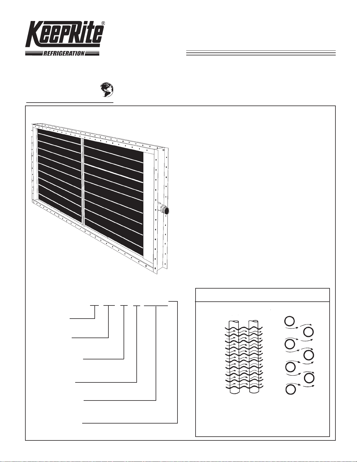
T ype KSH
Features
RIPPLED FINS produce a rippled air flow pattern for
maximum heat transfer. These ripples also assure
permanent “fin-tube bond” through greater flexibility under
expansion and contraction.
ST AGGERED TUBES create air turbulence to give
maximum air side heat transfer.
MECHANICAL EXP ANSION BOND ensures permanent
metal to metal contact. (No low conductivity materials
used as a bonding agent).
FIN COLLARS are drawn wide and smooth to provide
maximum contact area.
NOMENCLATURE
K SH 8 2 24 x 48
KEEPRITE
REFRIGERATION
COIL TYPE
STEAM HEAT
FINS PER INCH
(STD. 8 FINS/INCH)
ROWS DEEP
“W” DIMENSION
(SEE P 4)
NOMINAL TUBE
LENGTH
STEAM BAFFLE disperses entering steam thereby
preventing blow through or short circuiting and
ensuring equal steam pressure throughout the supply
header.
THE IMPORT ANT DIFFERENCE
KEEPRITE REFRIGERATION
SURFACE
RIPPLED FINS STAGGERED TUBES
Highly Efficient result
Rippled Air Flow assure intimate
and prolonger contact between air
and the cooling surface.
Page 2
COIL SELECTION
KSH Coils are a general purpose coil for reheat applications or when
outdoor air temperature is
above 35°F.
For applications where
modulating control is required and entering air is below freezing
“Type DT” coils should be used.
KSH Coils are not recommended for use with steam pressures
above 25 PSIG.
The following example outlines the procedure for determining the coil
size, fin spacing, rows deep, etc.
SPECIFIED:
(a) Air Volume (Std. Air)........................................................8,000 CFM
(b) Design Face Velocity (Max,)...............................................700 FPM
(c) Steam Pressure....................................................................10 PSIG
(d) Entering Air Temperature..........................................................40°F.
(e) Leaving Air Temperature.........................................................125°F.
(f) Heating Load............................................................741,000 BTU/Hr.
REQUIRED:
(a) Coil Size and Model (d) BTU/Hr. Capacity.
(b) Coil Nomenclature (e) Lbs. of Condensate/Hr.
(c) Leaving Air Temperature (f) Air Side Friction Loss
PROCEDURE:
A. Determine Coil Face Dimensions
1. Coil Face Area Req’d =
Design Face Vel. 700
SpecifiedCFM*
=
8000
11.4 sq. ft.
=
*(Specified CFM at Std. Air)
2. From Table 3, select a “24 x 72” coil with 12 sq. ft. face area as
having face dimensions most suitable for this job.
B. Determine Coil Model Number
1. Temperature Rise Required = 125° - 40° = 85° F .
2. From Table 2, the Conversion Factor for 10 psig steam and 40° F.
entering air is .878.
3. Then,
Conv. Factor .878
4. Actual Coil Face V el. =
Coil Face Area 12
Req’d Temp. Rise
850
=
= 96.8° F. (Req’d Base Rise)
Specified CFM = 8000
= 667 FPM
5. From Figure 1 (or Table 1 by interpolation), find “Model 82” coil has
Base Temp. Rise of 100° F. at 667 FPM. Hence, select a “Model
82” coil.
C. Determine Coil Nomenclature ‡
From Coil Designation Chart, below, determine coil nomenclature as
follows: KSH82 - 24x72.
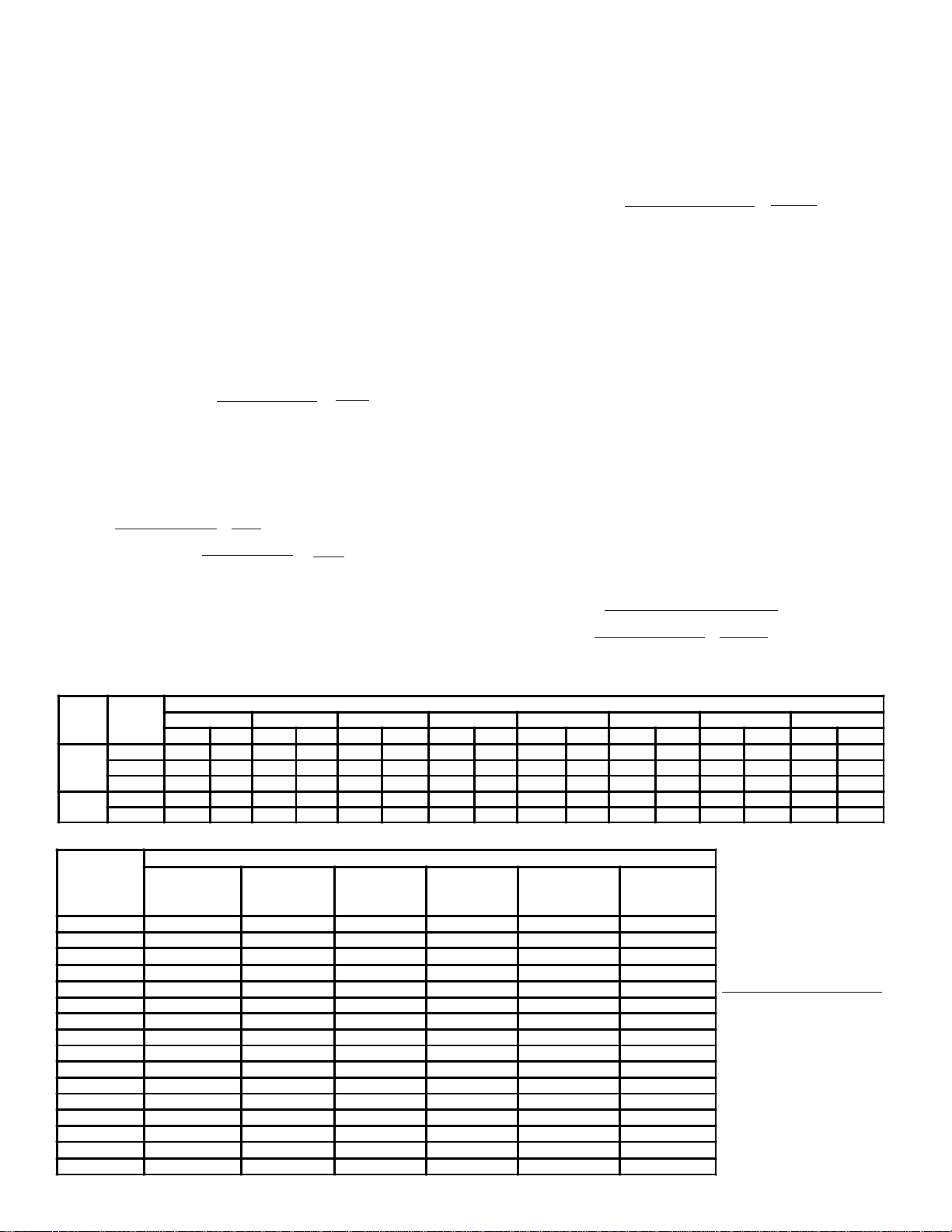
TABLE 1 BASE TEMPERATURE RISE AND STATIC PRESSURE
Temp. Rise based on 5 psig. steam and 0° F Ent. Air Temp. --- Static Pressure based on Std. Air (70°F, and 29.92” Hg.)
ROWS FACE VELOCITY - FEET PER MINUTE - STANDARD AIR
DEEP MODEL 300 400 500 600 700 800 1000 1200
141
ROW 71
272116.4 .047 106.8 .076 98.8 .112 92.0 .153 86.3 .199 81.5 .251 73. 8 .368 67.6 .503
ROW 82 130.7 .053 120 .3 .087 112.0 .128 104.4 .175 98.0 .228 93.0 .287 84.2 .421 77.4 .576
T.R. S.P. T.R . S . P. T.R. S.P. T.R. S . P. T.R . S.P. T.R . S.P. T.R . S.P. T.R . S.P.
51.5 .020 45.4 .034 41.2 .049 37.9 .067 35.3 .087 33.1 .110 30.0 . 162 27.4 .221
72.8 .027 64.4 .044 58.5 . 065 53.9 .088 50.3 .115 47.1 .145 42.6 .213 38.8 .291
81 83.8 .031 74.4 .051 67.6 .074 62.2 .101 57.9 .132 54.7 .166 49.1 .243 44.9 .333
TABLE 2 STEAM CONVERSION FACTORS
ENT. STEAM PRESSUR E PS IG - STEAM TEMPERATURE ° F - LATENT HE AT BTU PER LB.
AIR 0 2 5 10 15 25
TEMP. 212° 218° 227 ° 239° 250° 267°
°F. 970 966 961 953 946 934
-30 1.065 1.094 1.132 1. 186 1.232 1.307
-20
-10
0 .933 .9 62 1.000 1.054 1.099 1.175
10
20
30 .8 01 .830 .868 .9 22 .967 1.042
40
50
60 .669 .698 .736 .790 .835 .910
70
80 .581 .610 .648 .702 .747 .822
90 .537 .566 .604 .658 .703 .772
100
125 .383 .412 .450 .504 .549 .624
150 .273 .302 .340 .394 .439 .514
1.021 1.050 1.088 1.142 1. 188 1.263
.977 1.006 1.004 1.098 1.144 1.219
.889 .9 18 .956 1.010 1.056 1.131
.845 .8 74 .912 .966 1.011 1.087
.757 .786 .824 .878 .923 .998
.713 .742 .780 .834 .879 .954
.625 .654 .692 .746 .791 .866
.493 .522 .560 .614 .659 .734
D. Determine Leaving Air Temperature
1. Actual Temp. Rise = Base Rise x Conv. Factor
2. Actual Temp. Rise @ 10 psig and 40°F. EA = 100 x .878 = 87.8°F
3. Leaving Air Temperature = 40° + 87.8° = 127.8°F.
E. Determine BTU/Hr. Capacity
1. BTU/Hr. Capacity = 1.09 x Temp. Rise x CFM
= 1.09 x 87.8 x 8000 = 766,000
F. Determine Lbs. of Condensate/Hr.
1 .Lbs. of Cond./Hr. =
Latent heat @ 10 PSIG 953
Total BTU/Hr. Capacity = 766.000
= 804
G. Determine Air Side Friction
1. Air Friction = .210 inches of water from Fig. 1
(or from Table 1 by interpolation).
COILS IN SERIES
Occasionally, it may be necessary to use two or more coils in series in
order to heat the air to the required final temperature. Likewise, if row
control is required, it would be necessary to furnish individual coils.
Suppose, in the preceding example, that it had been desired to have
a final air temperature considerably higher than 125°F. It would then
be necessary to select an additional coil or coils to place after the
first coil. In calculating the temperature rise through these additional
coils, the leaving air temperature of the first coil is used as the
entering air temperature to the second coil, etc. The method of
computation is identical to that previously shown.
DETERMINA TION OF MIXTURE AIR TEMPERA TURE
Air entering the coil is usually a mixture of both return air and fresh air.
Determine mixture air temperature per following example:
SPECIFIED:
Return Air Temperature...............................................................70°F.
Fresh Air Temperature.............................................................-200 F.
CFM (Return Air).........................................................................2000
CFM (Fresh Air)...........................................................................1000
REQUIRED:
Mixture Air Temperature (° F.)
SOLUTION:
MixtureAirTemp.=
(2000) x (70) + (1000) x (-20)
3000
= 140,000 + (-20,000) = 120,000 = 40°F.
3000 3000
To Calculate Conversion
Factors not given in above
table, use following formula:
Conversion factor =
Steam Temp. - Ent. Air T emp.
227
Page 3

140
130
120
110
100
90
COIL SELECTION
BASE TEMPERATURE RISE ( ° F ) @ 5 PSIG STEAM & 0°F ENT. AIR
80
70
60
50
40
30
20
10
200 300 400 500 600 700 800 900 1000 1100 1200
FACE VELOCITY - FEET PER MINUTE (Std. Air)
0.7
0.6
0.5
0.4
0.3
0.2
0.1
0
AIR SIDE FRICTION LOSS (Inches water)
TABLE 3 COIL SIZES - NOMINAL FACE AREA - SQ. FT.
"W" NOMINAL TUBE LENGTH - NTL - (INCHES)
INCHES 12 15 18 21 24 30 36 42 48 54 60 66 72 78 84 90 96 102 108 114 120
6 .50 .62 .75 .87 1.00 1.25 1.50 1.75 2.0 2.2 2.5 2.7 3.0
9 .75 .94 1.12 1.31 1.50 1.87 2.25 2.62 3.0 3.4 3.7 4.1 4.5
12 1.00 1.2 5 1.50 1.75 2.00 2.50 3.0 0 3.50 4.0 4.5 5.0 5.5 6.0 6.5 7.0 7.5 8.0 8.5 9.0 9.5 10.0
15 1.56 1.87 2.19 2.50 3.12 3.75 4.37 5.0 5.6 6.2 6.9 7.5 8.1 8.7 9.4 10.0 10.6 11.2 11.9 12.5
18 2.25 2.6 2 3.00 3.75 4.50 5.25 6.0 6.7 7.5 8.2 9.0 9.7 10.5 11.2 12.0 12.7 13.5 14.2 15.0
21 3.06 3.5 0 4.37 5.25 6.12 7.0 7.9 8.7 9.6 10.5 11.4 12.2 13.1 14.0 14.9 15.7 16.6 17.5
24
27 5.62 6.75 7.87 9.0 10.1 11.2 12.4 13.5 14.6 15.7 16.9 18.0 19.1 20.2 21.4 22.5
30 6.25 7.50 8.75 10.0 11.2 12.5 13.7 15.0 16.2 17.5 18.7 20.0 21.2 22.5 23.7 25.0
33
36 9.00 10.50 12.0 13.5 15.0 16.5 18.0 19.5 21.0 22.5 24.0 25.5 27.0 28.5 30.0
4.00 5.00 6.00 7.00 8.0 9.0 10.0 11.0 12.0 13.0 14.0 15.0 16.0 17.0 18.0 19.0 20.0
8.25 9.62 11.0 12.4 13.7 15.1 16.5 17.9 19.2 20.6 22.0 23.4 24.7 26.1 27.5
Page 4
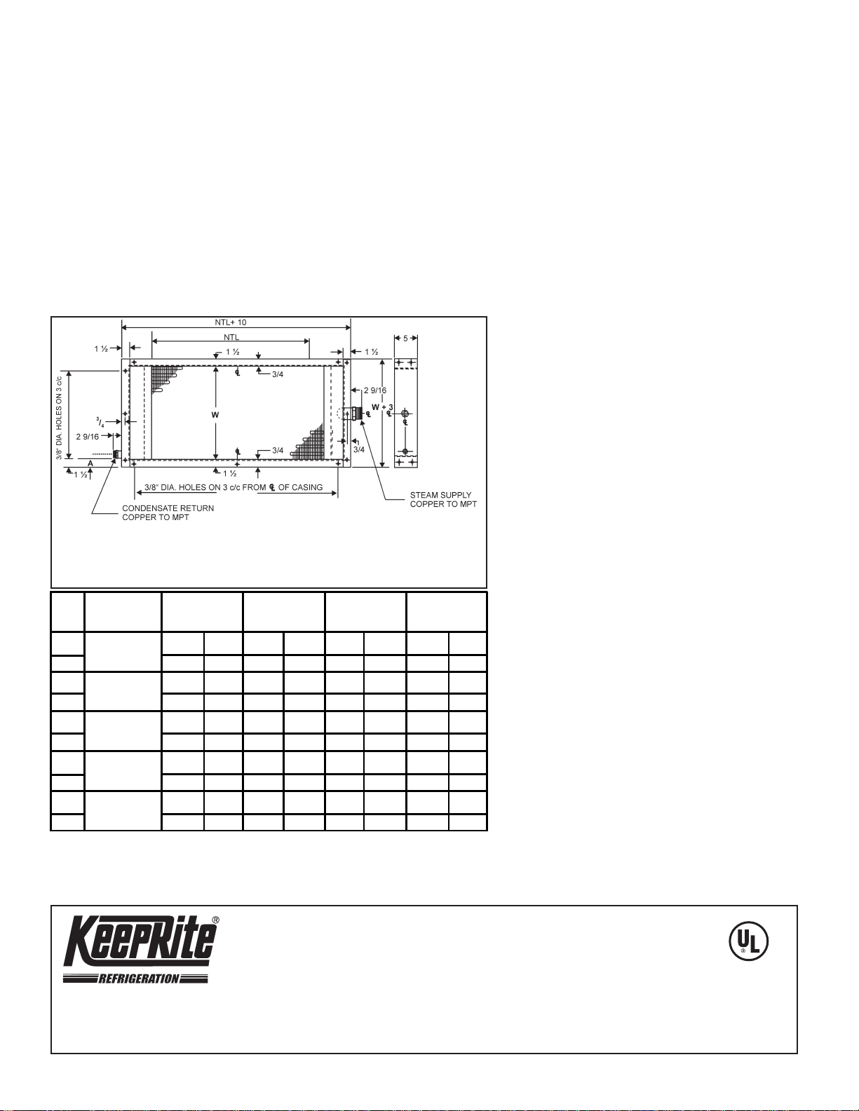
SPECIFICA TIONS
US
C
03/17/07
INST ALLATION RECOMMENDA TIONS
PRIMARY SURFACE - 5/8" O.D. round copper tube on 1-1 /2" centres.
SECONDARY SURF ACE - Rippled, full plate type, aluminum fins. (Copper fins available
on special order.)
HEADERS - Extra heavy seamless copper tubing.
HEADER END CAPS - Heavy gauge, die formed copper.
BRAZING - All core joints are made with copper brazing alloys.
CASING - Die formed, 16 gauge (or heavier), galvanized steel, with3/8" bolt holes in
mounting flanges. Casing design permits coil to “float” under expansion and
contraction.
TESTS - Completed core tested at 300 psig air under water.
CONNECTIONS - Male pipe thread.
OPERATING CONDITIONS - Standard cores are recommended to 25 psig steam
pressures and temperatures up to 240°F.
COILS - are single tube for standard application.
DIMENSIONAL DA T A
Rows
Deep
1
2
1
2
1
2
1
2
1
2
* Finned length may vary from N.T.L. depending on rows and supply connection used:
"W"
Dim.
3" to 12"
2 to 8
Rows High
13 1/2" to 18"
9 to 12
Rows High
19 1/2" to 24"
13 to 16
Rows High
31 1/2" to 39"
21 to 26
Rows High
25 1/2" to 30"
17 to 20
Rows High
24" to 48"
Fin. Lgth.
Supply Return
1 1/4" 1" 1 1/4" 1" 1 1/4" 1" 1 1/4" 1"
1 1/2" 1 1/4" 1 1/2" 1 1/4" 1 1/2" 1 1/4" 1 1/2" 1 1/4"
1 1/4" 1" 1 1/4" 1" 1 1/2" 1 1/4" 1 1/2" 1 1/4"
1 1/2" 1 1/4" 1 1/2" 1 1/4" 2" 1 1/2" 2" 1 1/2"
1 1/4" 1" 1 1/2" 1 1/4" 1 1/2" 1 1/4" 2" 1 1/2"
1 1/2" 1 1/4" 2" 1/1/2" 2" 1 1/2" 2 1/2" 1 1/2"
1 1/4" 1" 1 1/2" 1 1/4" 2" 1 1/2" 2" 1 1/2"
1 1/2" 1 1/4" 2" 1 1/2" 2 1/2" 1 1/2" 2 1/2" 1 1/2"
1 1/2" 1 1/4" 2" 1 1/2" 2" 1 1/2" 2 1/2" 1 1 /2"
2" 1 1/2" 2 1/2" 1 1/2" 2 1/2" 1 1/2" 2 1/2" 1 1/2"
1 ROW 1 1/4” MPT _ + 1/2” MPT_STANDARD 2”
2 ROW 1 1/2” MPT , 2” MPT, 2 1/2” MPT _ -2 1/4”
49" to 72"
Fin. Lgth.
Supply Return
_
73" to 96"
Fin. Lgth.
Supply Return
-1” 2 1/2”
97" to 120"
Fin. Lgth.
Supply Return
_
-1 1/4”
1. All piping shall be in accordance with accepted
industry standards.
2. Whenever possible, coils should be installed with
tubes in a vertical position. When coils are installed
with tubes in a horizontal position, pitch coil
towards return tap a minimum of 1/4" per foot - use
a spirit level.
3. Support piping independently of coils and provide
swing joints to prevent damage from expansion and
contraction.
4. Do not bush return connection-run piping full size to
trap.
5. Provide proper vents to expel air and other non
condensibles to avoid “air binding”.
6. Do not drip steam mains through coils.
7. Coils in series in the air flow (coils having unlike
condensate loads) should be individually trapped.
8. Coils side by side (having similar condensate loads)
can be controlled by a common valve and common
trap providing individual check valves are used.
However, it is always preferable to use individual
traps.
9. Each coil or group of coils that is individually
controlled must be individually trapped.
10. Exercise caution in selecting steam coils, valves
and traps. Do not OVERSIZE coils and valves - do
not UNDERSIZE traps. Always install strainers
ahead of valves and traps.
11. Provision should always be made to thoroughly mix
fresh and return air before it enters coil. Also,
temperature control elements must be properly
located to obtain true air mixture temperatures.
12. FOR ENTERING AIR TEMPERATURE BELOW 35°F.
special precaution must be taken to prevent damage
due to freeze-up of Steam Coils -
A. SPECIAL STEAM DISTRIBUTING TYPE COILS
SHOULD BE USED. Consult local KeepRite Sales
Representative for recommendations.
B. VALVE CONTROL (Atmospheric and Vacuum
Systems only).
1. TWO POSITION VALVE: Steam supply pressure
to valve must be maintained at 5 psig (minimum)
at all times. Control element should be located
in entering air stream and set to open valve
wide when entering air drops to 35°F.
2. MODULATING “V” PORT TYPE V ALVE:
Modulating valves are not recommended for use
with steam coils when entering air temperature
is below 35°F.
C. FACE AND BY P ASS DAMPER CONTROL
(Atmospheric, Vacuum and Pressure Systems): S team
supply pressure on coil must be maintained at 5 psig
(minimum) at all times.
D. FRESH AIR DAMPERS: Provision must be made to
close fresh air dampers if steam supply pressure
fails below minimum specified. Damper motor must
be spring return type and damper blades must be
overlapping and tight fitting - preferably gasketed.
Control system must delay opening of fresh air
dampers for 10 minutes at startup of system.
E. Use of a vacuum breaker piping arrangement is
recommended to prevent back flow of condensate at
high return main pressure.
NA TIONAL REFRIGERA TION &
AIR CONDITIONING CANADA CORP.
CANADA
159 ROY BL VD., BRANTFORD, ONT ARIO, CANADA N3R 7K1
PHONE: 1-800-463-9517 (519)751-0444 FAX (519)753-1140
Due to National Refrigeration’s policy of continuous product improvement, we reserve the right to make changes without notice.
USA
985 WHEELER WA Y, LANGHORNE, P A. 19047 USA
PHONE:1-888-KEEPUS1 OR 1-888-533-7871
 Loading...