

Page 1
PRODUCT DATA &
INSTALLATION
Bulletin K30-KMP-PDI-50-4
KMP
Medium Profile
Unit Cooler
Air, Electric, Hot Gas
& Warm Fluid Defrost
1082851-50
We are on the Internet
www.keepriterefrigeration.com
Electrical Power:
200-220/1/50, 200-220/3/50,
380-460/1/50, 380-400/3/50
CONTENTS
Nomenclature........................................................................................................................ 2
Page
Features & Options..............................................................................................................2
Capacity Data...................................................................................................................... 3
Electrical Data...................................................................................................................... 4 - 9
Wiring Diagrams.................................................................................................................. 10 - 18
Dimensional Data/S pecifications...................................................................................... 19 - 20
Shipping Weights................................................................................................................21
Glycol Fluid Cooler Data.................................................................................................... 21
Factory Installed Distributor Nozzles................................................................................. 22
Recommended Exp ansion Valve Selections................................................................... 23 - 25
Installation Instructions........................................................................................................ 26 - 28
Hot Gas Piping Schematics.............................................................................................. 29 - 30
Generic Service Parts List................................................................................................. 31 - 32
Warranty....................................................................................................................... ........ 35
Project Information.............................................................................................................. 35
“As Built” Service Parts...................................................................................................... BACK
Page 2
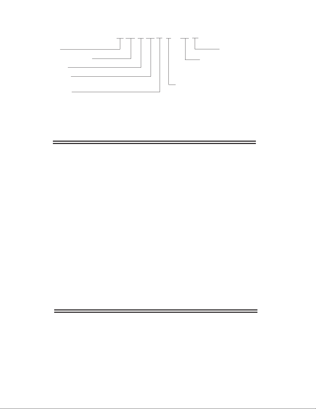
NOMENCLATURE
K MP 3 15 V E - T5 A
K = KeepRite
Medium Profile Unit Cooler
Number of Fans
Nominal Capacity:
x 1000 @ 10°F TD, Btu/H, R404A
Application Range:
M = Medium to High T emp 6 FPI (10°F to 45°F Evap Temp) *
L = Low Temp 6 FPI (-40°F to 0°F Evap Temp)
V = Low Temp 4 FPI (-40°F to 0°F Evap Temp)
W = Fluid Air Cooler (with water or glycol)
* except “488M”, which is 8 FPI
STANDARD FEATURES
• Modern look
• Totally enclosed high efficiency PSC motors
• High efficiency and high strength fan guard
Generation: A = 1
Voltage:
S6 = 200-220/1/50 T7 = 200-220/3/50
S9 = 380-400/1/50 T9 = 380-400/3/50
Defrost:
A = Air E = Electric
T = 3 Pipe Hot Gas w/ Electric Heater Pan
or Warm Fluid w/ Electric Heater Pan for Fluid Air Coolers
H = 3 Pipe Hot Gas w/ Hot Gas Loop Pan (optional)
G = Reverse Cycle w/ Electric Heater Pan
R = Reverse Cycle w/ Hot Gas Loop Pan (optional)
st
• Proven motor/fan/motor mount design
• Liquid line solenoid valve wire harness factory
installed
• Hinged doors
• Compact
• Internally enhanced tubing
• More uniform air flow
• Reverse cycle & 3 pipe hot gas available
• Ample electrical and header compartments
• Lower heater wattage
OPTIONAL FEATURES
• Hot gas loop pan with hot gas defrost models
• Wire fan guard
• Schrader valve on suction header
• Positive slope, hinged drain pan
• Central drain connections (approximate)
• Universal drain fitting
• Large 3/4" ID (3/4" MPT) drain hole
• Shipped in upright position
• Factory installed expansion valve,
solenoid valve and room thermostat
- 2 -
Page 3
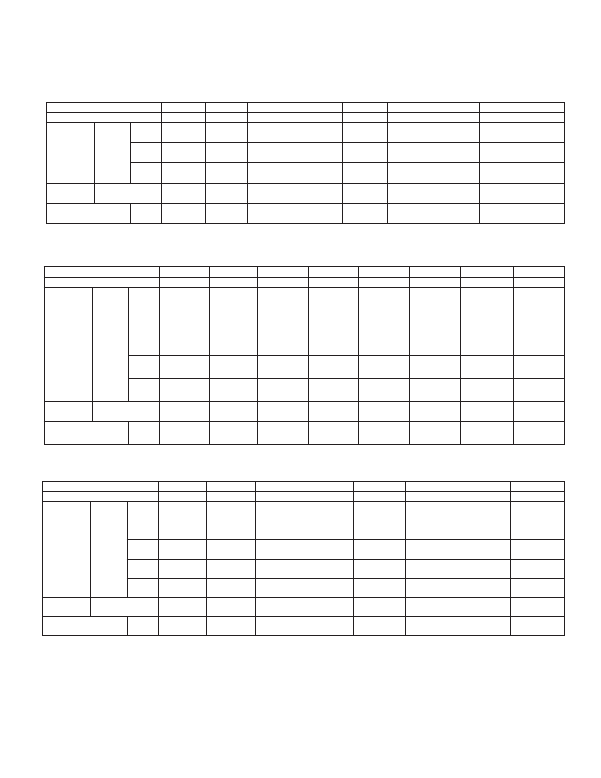
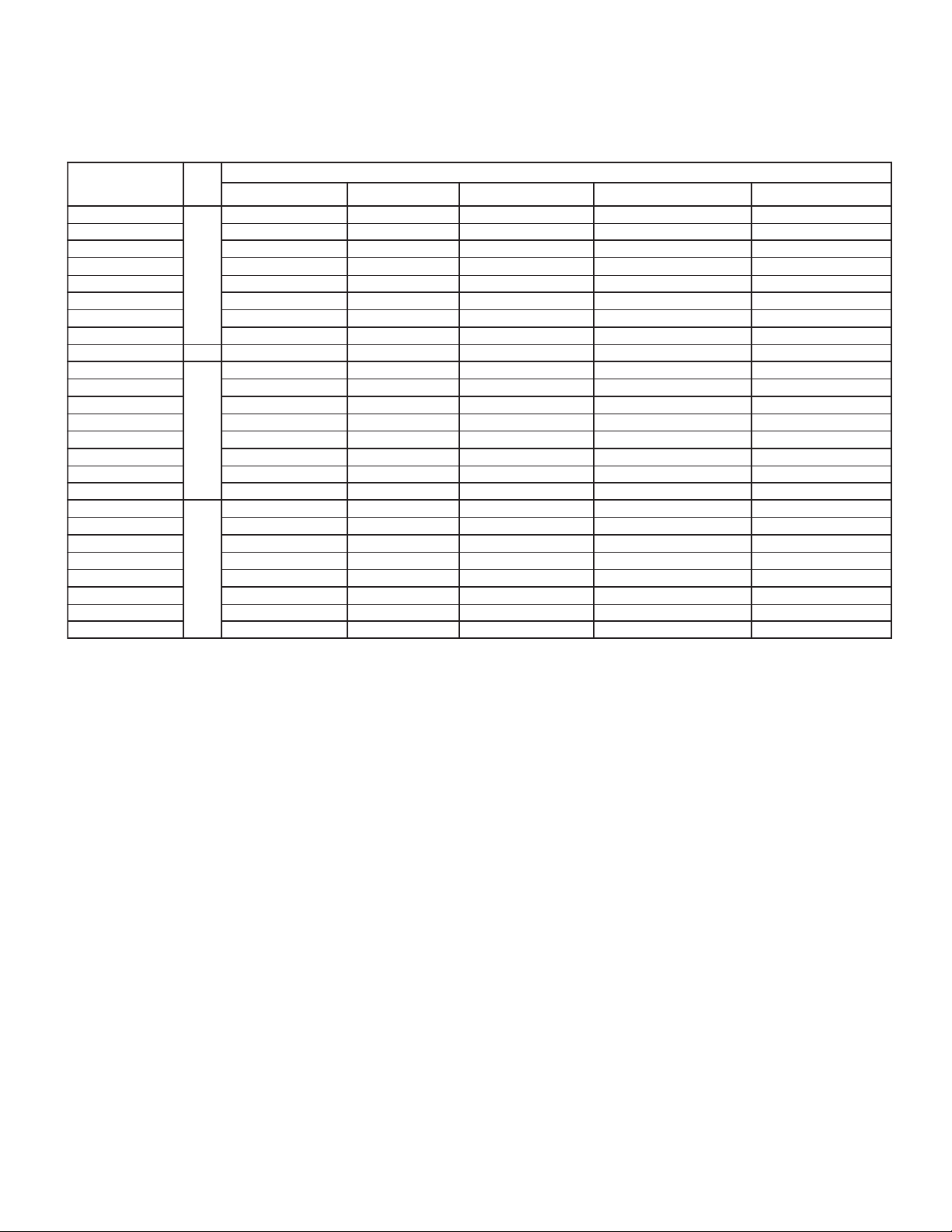
CAPACITY DATA
ALL MODELS
Medium Temperature Models - Capacity @ 6 F.P.I. *
sledoM.pmeTmuideMM811M221M822M632M542M553M863M084*M884
snaFfOrebmuN112223344
00133
)0079(
0387
)5922(
0577
)1722(
0275
)0072(
0.7
)2.3(
00313
00503
00492
00172
00642
0275
0.7
)2.3(
00314
)00121(
00001
)1392(
0099
)2092(
0045
)0552(
1.9
)1.4(
)0919(
)0598(
)0368(
)0597(
)0227(
)0072(
yticapaC
HUTB
)STTAW(
F° )C°(
olFriAMFC ( )S/L
w
)A404R(
1
52
pavE
.pmeT
egrahCtnaregirfeR
)4-(
1
5
)9-(
01
)21-(
.BL
)GK(
.I.P.F8erasledom"M884"*
0056
)0584(
0293
)9411(
0883
)7311(
0682
)0531(
6.3
)6.1(
00202
)0395(
0005
)5641(
0594
)1541(
0962
)0721(
8.4
)2.2(
00752
)0557(
0816
)1181(
0216
)4971(
0606
)0682(
2.4
)9.1(
Low Temperature Models - Capacity @ 6 F.P.I.
sledoM.pmeTwoLL611L911L522L232L042L843L653L174
snaFfOrebmuN 11222334
yticapaC
HUTB
)STTAW(
wolFriAMFC ( )S/L
)A404R(
F° )C°(
0
)81-(
01-
pavE
.pmeT
egrahCtnaregirfeR
)32-(
02-
)92-(
03-
)43-(
04-
)04-(
.BL
)GK(
00251
)0544(
00051
)0934(
00741
)0134(
00731
)0204(
00721
)0273(
0682
)0531(
6.3
)6.1(
00581
)0245(
0
0081
)0825(
00
571
)0215(
002
61
)0474(
1
0074
)0134(
0
962
)0721(
8.4
)2.2(
00342
)0217(
00632
)0396(
00032
)0476(
00212
)0326(
00491
)0965(
0606
)0682(
7.4
)1.2(
50Hz
00505
)00841(
07721
)3473(
04621
)5073(
0858
)0504(
01
)7.4(
00983
)00411(
00973
)00111(
00863
)00801(
00143
)00001(
00013
)0019(
0045
)0552(
4.9
)2.4(
00426
)00381(
04451
)5254(
09251
)1844(
0908
)0283(
41
)3.6(
00454
)00331(
00054
)00231(
00044
)00921(
00314
)00121(
00283
)00211(
0858
)0504(
01
)7.4(
00737
)00612(
02281
)0435(
03081
)4825(
00801
)0115(
61
)4.7(
00525
)00451(
00225
)00351(
00515
)00151(
00484
)00241(
00054
)00231(
0908
)0283(
41
)3.6(
00808
)00732(
09802
)3216(
08602
)1606(
00201
)0
084(
61
7(
)4.
00276
)00791(
00566
)00591(
00156
)00191(
00016
)00971(
00365
)00561(
00801
)0115(
61
)4.7(
Low Temperature Models - Capacity @ 4 F.P.I.
sledoMIPF4.pmeTwoLV311V711V222V822V432V933V053V954
snaFfOrebmuN11222334
00361
)0774(
00061
)0964(
00651
)0854(
541
00
)0624(
00431
)0493(
0682
)0531(
8.4
)2.2(
yticapaC
HUTB
)STTAW(
wolFriAMFC ( )S/L
)A404R(
F° )C°(
0
)81-(
01-
pavE
.pmeT
egrahCtnaregirfeR
)32-(
02-
)92-(
03-
)43-(
04-
)04-(
.BL
)GK(
00221
953(
)0
00121
3(
)065
00911
)0053(
00211
)0923(
00501
)0703(
0303
)0341(
3
6.
)6.1(
Capacities rated using R404A with 10°F (5.6°C) TD & 100°F (38°C) liquid temperature.
Capacities at other TD within a range of 8 to 15 °F (4.4 to 8.3°C) are directly proportional to TD, or use formula:
Capacity = Rated capacity ÷ 5.6 x TD.
For capacities at TD outside of range 8 to 15 °F (4.4 to 8.3°C), or liquid temperature lower than 75°F (24°), consult factory .
00012
)0516(
00702
)0706(
00202
)0395(
00981
)0355(
00471
)0905(
0046
)0203(
7.4
)1.2(
00962
)0097(
00462
)0477(
00752
)0557(
00932
)0107(
00022
)0446(
0606
)0682(
0.7
)2.3(
00523
)0259(
00913
)0539(
00313
)0719(
00292
)0558(
00862
)0787(
0275
)0072(
4.9
)2.4(
00204
)00811(
00283
)00211(
00853
)00501(
00823
)0269(
00292
)0558(
0909
)0924(
01
)7.4(
00505
)00841(
00884
)00341(
00064
)00531(
00324
)00421(
00973
)00111(
0858
)0504(
41
)3.6(
00655
)00361(
00945
)00161(
00245
)00951(
00215
)00051(
00474
)00931(
00411
)0935(
61
)4.7(
- 3 -
Page 4
ELECTRICAL DATA - 200-220/1/50
AIR DEFROST &
50Hz
HOT GAS DEFROST WITH HOT GAS LOOP PAN MODELS
L611†A6SL911†A6S-
-#L843
V311†A6SV711†A6S-
V822
LEDOMIPF
A6S-#M811
A6S-#M221
S-#M822
A6
A6S-#M632
A6S-#M542
A6S-#M553
A6S-#M863
A6S-#M084
6S-#M884
A
A6S-#L522
A6S-#L232
A6S-#L042
A6S
A6S-#L653
A6S-#L174
A6S-#V222
A6S-#
A6S-#V432
A6S-#V933
A6S-#V053
A6S-#V954
SROTOMNAF
YTITNAUQPHLATOTALF)A(YTICAPMA.CRIC.NIM)SPMA(ESUF.XAM
13/17.11.251
13/17.11.251
23/14.38.351
6
84 3/18.62.751
6
4
NotrefeR.RroH,A=#
23/14.38.351
23/14.38.351
33/11.55.551
33/11.55.551
43/18.62.751
13/17.11.251
13/17.11.251
23/14.38.351
23/14.38.351
23/14.38.351
33/11.55.551
33/11.55.551
43/18.62.751
13/17.11.251
13/17.11.251
23/14.38.351
23/14.38.351
23/14.38.351
33/11.55.551
33/11.55.551
43/18.62.751
sliatedroferutalcnemo
sliatedroferutalcnemoNotrefeR.RroH=†
- 4 -
Page 5
ELECTRICAL DATA - 380-400/1/50
AIR DEFROST &
50Hz
HOT GAS DEFROST WITH HOT GAS LOOP PAN MODELS
22
L611†A9SL911†A9S-
-#L843
V311†A9S
V711†A9S
LEDOMIPF
A9S-#M811
A9S-#M221
S-#M822
A9
A9S-#M632
A9S-#M542
A9S-#M553
A9S-#M863
A9S-#M084
9S-#M884
A
A9S-#L522
A9S-#L232
A9S-#L042
A9S
A9S-#L653
A9S-#L174
A9S-#V222
A9S-#V8
A9S-#V432
A9S-#V933
A9S-#V053
A9S-#V954
SROTOMNAF
YTITNAUQPHLATOTALF)A(YTICAPMA.CRIC.NIM)SPMA(ESUF.XAM
13/19.01.151
13/19.01.151
23/18.10.251
6
84 3/16.38.351
6
4
trefeR.RroH,A=#
23/18.10.251
23/18.10.251
33/17.29.251
33/17.29.251
43/16.38.351
13/19.01.151
13/19.01.151
23/18.10.251
23/18.10.251
23/18.10.251
33/17.29.251
33/17.29.251
43/16.38.351
13/19.01.151
13/19.01.151
23/18.10.251
23/18.10.251
23/18.10.251
33/17.29.251
33/17.29.251
43/16.38.351
sliatedroferutalcnemoNo
sliatedroferutalcnemoNotrefeR.RroH=†
- 5 -
Page 6
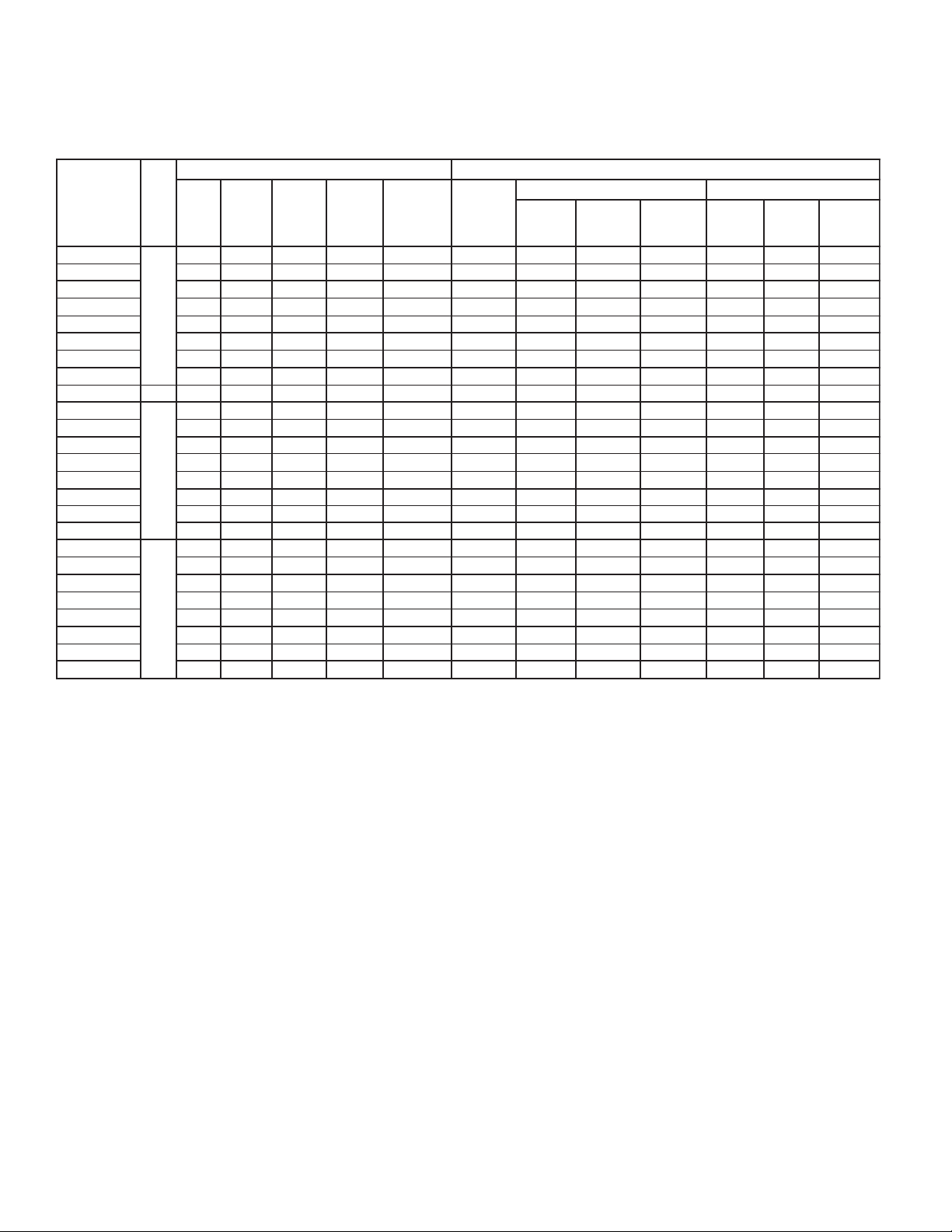
ELECTRICAL DATA -
200-220/1/50 & 200-220/3/50
ELECTRIC DEFROST MODELS
SROTOMNAF SRETAEHTSORFED
LEDOMIPF
A*-EM811
A*-EM221
A*-EM822
A*-EM632
6
A*-EM542
A*-EM553
A*-EM863
A*-EM084
A*-EM884
84 3/18.62.7510079445506037304
A*-EL611
A*-EL911
A*-EL522
A*-EL232
6
A*-EL042
A*-EL843
A*-EL653
A*-EL174
A*-EV311
A*-EV711
A*-EV222
A*-EV822
4
A*-EV432
A*-EV933
A*-EV053
A*-EV954
.YTQPH
13/17.11.25105034171025.92151
13/17.11.251050341710
23/14.38.3510665622353812252
23/14.38.3510665622353812252
23/14.38.3510665622353812252
33/11.55.551072883740
33/11.55.5510728837405622353
43/18.62.7510079445506037304
13/17.11.251050341710
13/17.11.25105034171025.92151
23/14.38.3510665622353812252
23/14.38.3510665622353812252
23/14.38.3510665622
33/11.55.5510728837405622353
33/11.55.5510728837405622353
43/18.62.7510079445506037304
13/17.11.2510503417
13/17.11.25105034171025.92151
23/14.38.3510665622353812252
23/14.38.3510665622353812252
23/14.38.35106656
33/11.55.5510728837405622353
33/11.55.5510728837405622353
43/18.62.7510079445506037304
oNotrefeR.7Tro6S=*
ALF
LATOT
ACM
)A(
sliatedroferutalcnem
.XAM
ESUF
)SPMA(
LATOT
STTAW
LATOT
SPMA
22353812252
05/1/022-00205/3/022-002
ACM
)A(
353812252
1025.92151
.XAM
ESUF
)SPMA(
25.92151
5622353
25.92151
LATOT
SPMA
50Hz
ACM
)A(
.XAM
ESUF
)SPMA(
-6 -
Page 7
LEDOMIPF
EL611
EV822
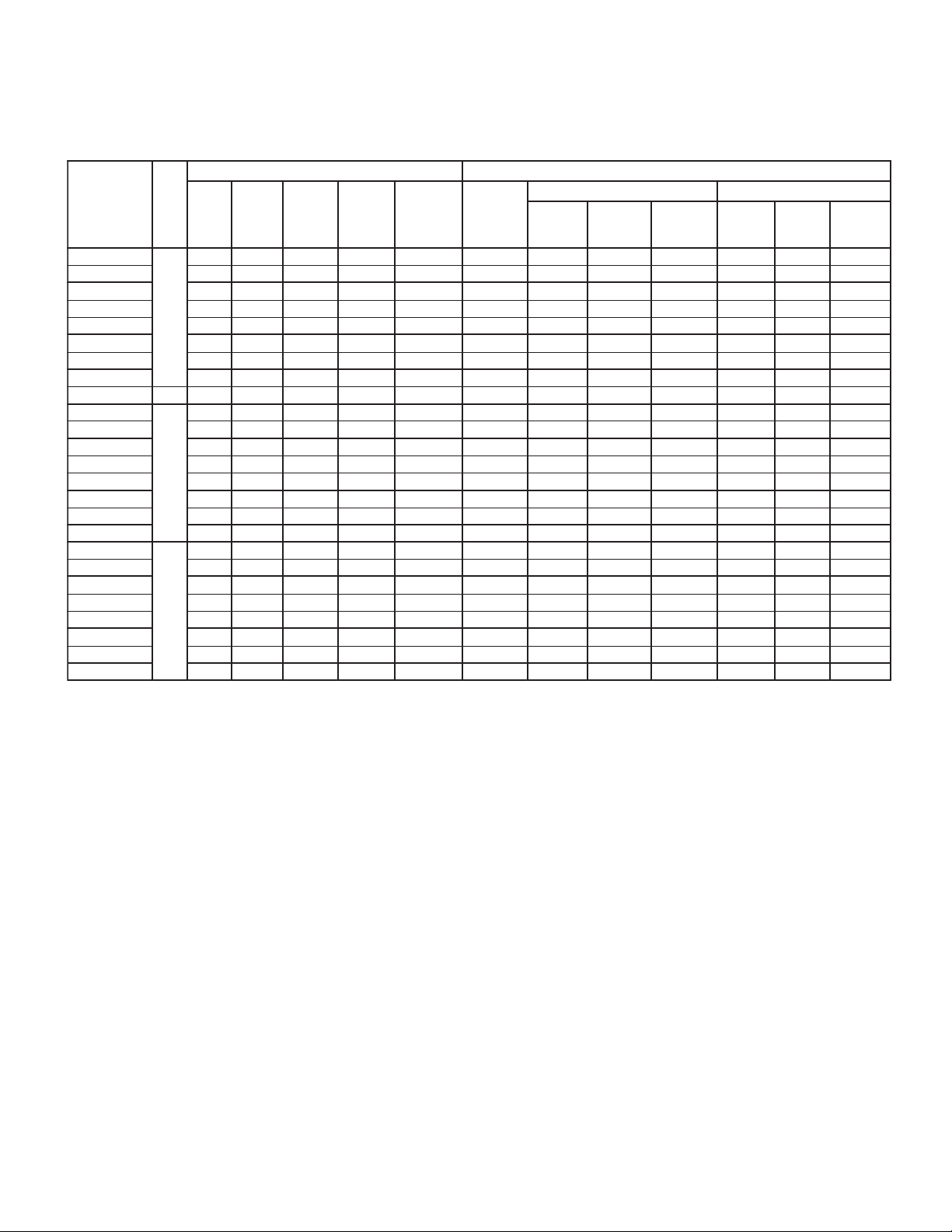
ELECTRICAL DATA -
380-400/1/50 & 380-400/3/50
ELECTRIC DEFROST MODELS
SROTOMNAF SRETAEHTSORFED
.YTQPH
A*-EM811
A*-EM221
A*-EM822
A*-EM632
A*-EM542
A*-EM553
A*-EM863
A*-EM084
A*-EM884
A*A*-EL911
A*-EL522
A*-EL232
A*-EL042
A*-EL843
A*-EL653
A*-EL174
A*-EV311
A*-EV711
A*-EV222
A*A*-EV432
A*-EV933
A*-EV053
A*-EV954
13/19.01.15105036.75.9516.4651
13/19.01.15105036.
23/18.10.25108652.4181027.81151
23/18.10.25108652.4181027.81151
6
23/18.10.25108652.4181027.81151
17.29.25101388.026203316102
33/
33/17.29.25101388.026203316102
43/16.38.35100793.420353519102
84 3/16.38.35100793.420353519102
13/19.01.15105036.75.9516.4651
13/19.01.15105036.75.9516.4651
23/18.10.25108652.4181027.81151
23/18.10.25108652.4
6
23/18.10.25108652.4181027.81151
33/17.29.25101388.026203316102
33/17.29.25101388.026203316102
43/16.
13/19.01.15105036.75.9516.4651
13/19.01.15105036.75.9516.4651
23/18.10.25108652.4181027.81151
23/18.10.25108652.4181027.81151
4
23/18.10.25108652.4181027.81151
33/17.29.25101388.026203316102
33/17.29.25101388.0
43/16.38.35100793.420353519102
ALF
LATOT
38.35100793.420353519102
ACM
)A(
sliatedroferutalcnemoNotrefeR.9Tro9S=*
.XAM
ESUF
)SPMA(
LATOT
STTAW
LATOT
SPMA
75.9516.4651
181027.81151
26203316102
05/1/004-08305/3/004-083
ACM
)A(
.XAM
ESUF
)SPMA(
LATOT
SPMA
50Hz
ACM
)A(
.XAM
ESUF
)SPMA(
- 7 -
Page 8
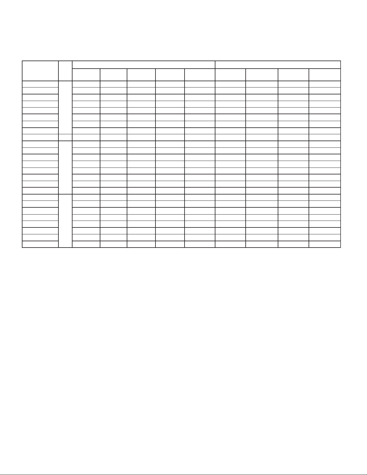
ELECTRICAL DATA - 200-220/1/50
HOT GAS DEFROST
50Hz
WITH DRAIN PAN HEATER MODELS
SROTOMNAF SRETAEHNAPNIARD
LEDOMIPF
A6S-^M811
A6S-^M221
A6S-^M822
A6S-^M632
S-^M542
^M884
32
6
A6
A6S-^M553
A6S-^M863
A6S-^M084
A6S-
84 3/18.62.75101310.64.751
A6S-^L611
A6S-^L911
A6S-^L522
A6S-^L2
6
A6S-^L042
A6S-^L843
A6S-^L653
A6S-^L174
A6S-^V311
A6S-^V711
A6S-^V222
A6S-^V822
4
A6S-^V432
A6S-^V933
A6S-^V053
A6S-^V954
.YTQPH
13/17.11.2519842.28.251
13/17.11.2519842.28.251
23/14.38.3512187.36.451
23/14.38.3512187.36.451
23/14.38.3512187.36.451
33/11.55.55103111.54.651
33/11.55.55103111.54.651
43/18.62.75101310.64.751
13/17.11.2519842.28.251
13/17.11.2519842.28.251
23/14.38.3512187.36.451
23/14.38.3512187.36.451
23/14.38.3512187.36.451
33/11.55.55103111.54.651
33/11.55.55103111.54.651
43
13/17.11.2519842.28.251
13/17.11.2519842.28.251
23/14.38.3512187.36.451
23/14.
23/14.38.3512187.36.451
33/11.55.55103111.54.651
33/11.55.55103111.54.651
43/18.62.75
/18.62.75101310.64.751
sliatedroferutalcnemoNotrefeR.GroT=^
ALF
LATOT
38.3512187.36.451
ACM
)A(
ESUF.XAM
)SPMA(
101310.64.751
LATOT
STTAW
SPMALATOT
ACM
)A(
A(
ESUF.XAM
)SPM
- 8 -
Page 9
884
LEDOMIPF
A9S-^M811
A9S-^M221
A9S-^M822
A9S-^M632
S-^M542
A9
A9S-^M553
A9S-^M863
A9S-^M084
A9S-^M
A9S-^L611
A9S-^L911
A9S-^L522
A9S-^L232
A9S-^L042
A9S-^L843
A9S-^L653
A9S-^L174
A9S-^V311
A9S-^V711
A9S-^V222
A9S-^V822
A9S-^V432
A9S-^V933
A9S-^V053
A9S-^V954
ELECTRICAL DATA - 380-400/1/50
HOT GAS DEFROST
50Hz
WITH DRAIN PAN HEATER MODELS
SROTOMNAF SRETAEHNAPNIARD
.YTQPH
13/19.01.1514040.13.151
13/19.01.1514040.13.151
23/18.10.2511767.11.251
6
84 3/16.38.35108017.24.351
6
4
23/18.10.2511767.11.251
23/18.10.2511767.11.251
33/17.29.2518393.29.251
33/17.29.2518393.29.251
43/16.38.35108017.24.351
13/19.01.1514040.13.151
13/19.01.1514040.13.151
23/18.10.2511767.11.251
23/18.10.2511767.11.251
23/18.10.2511767.11.251
33/17.29.2518393.29.251
33/17.29.2518393.29.251
43/16.38
13/19.01.1514040.13.151
13/19.01.1514040.13.151
23/18.10.2511767.11.251
23/18.10.2511
23/18.10.2511767.11.251
33/17.29.2518393.29.251
33/17.29.2518393.29.251
43/16.38.35108017.24
sliatedroferutalcnemoNotrefeR.GroT=^
ALF
LATOT
ACM
)A(
.35108017.24.351
ESUF.XAM
)SPMA(
LATOT
STTAW
767.11.251
SPMALATOT
ACM
)A(
.351
A(
ESUF.XAM
)SPM
- 9 -
Page 10
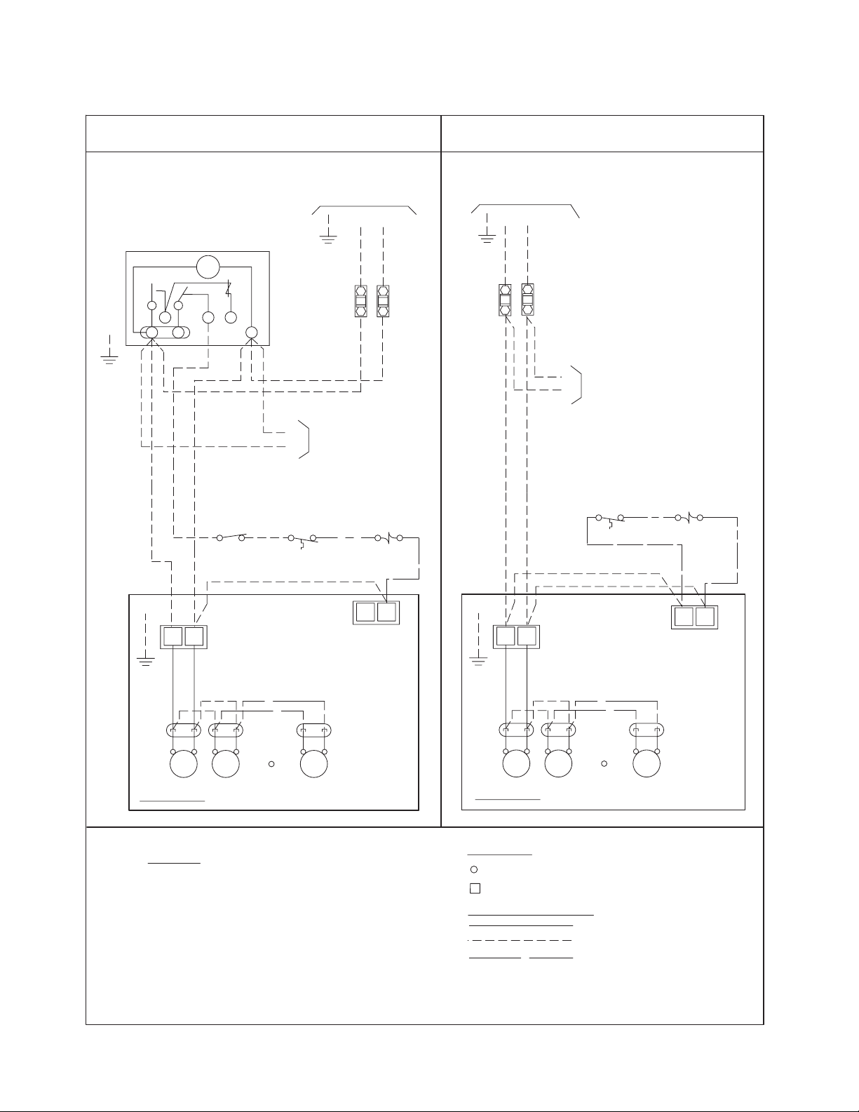
WIRING DIAGRAM - 200-220/1/50
AIR DEFROST MODELS
GND
WITH DEFROST TIME CLOCK
DEFROST CLOCK
PARAGON # 8145
OR EQUIVALENT
TM
3
1
2
PUMP DOWN
4X
SWITCH
(IF USED)
N
THERMOSTAT
NOTE #4
SPACE
REFER TO EVAPORATOR
NAMEPLATE FOR ELECTRICAL
REQUIREMENTS
L1
L2
GND
FUSE OR
CIRCUIT
BREAKER
NOTE #3
TO MULTIPLE EVAPS
M2
M1
(IF APPLIC)
LIQUID LINE
SOLENOID VALVE
NOTE #4
N.C.
WITHOUT DEFROST TIME CLOCK
REFER TO EVAPORATOR
NAMEPLATE FOR ELECTRICAL
REQUIREMENTS
L1
L2
GND
FUSE OR
CIRCUIT
BREAKER
NOTE #3
M2
M1
TO MULTIPLE
EVAPORATORS (IF APPLIC)
SPACE
THERMOSTAT
NOTE #4
LIQUID LINE
SOLENOID VALVE
NOTE #4
N.C.
M1
M2
TERMINAL BOARD
GND.
FAN
MTR
FAN
MTR
EVAPORATOR
NOTES
1). USE COPPER CONDUCTORS ONLY
2). USE 90°C WIRE (OR HIGHER)
3). OVERCURRENT PROTECTION FOR
EVAPORATOR FAN MOTORS AND DEFROST
HEATERS MUST NOT EXCEED MAXIMUM
VALUE SHOWN ON EVAPORATOR NAMEPLATE.
4). MAY BE FACTORY INSTALLED-MOUNTED AND
WIRED ON EVAPORATOR .
1-MP AIR 230V 11/05
FAN MO TO R
POWER
PLUGS
REFER TO
EVAPORATOR
FAN
MTR
DATA PLATE
FOR MOTOR
QUANTITY
N
4
M2
M1
GND.
TERMINAL BOARD
N
4
FAN MO TO R
POWER
PLUGS
REFER TO
FAN
MTR
EVAPORATOR
FAN
MTR
EVAPORATOR
FAN
MTR
DATA PLATE
FOR MOTOR
QUANTITY
TERMINALS
-COMPONENT TERMINAL
-TERMINAL BLOCK TERMINAL
CONDUCTORS/WIRING
FACTORY WIRING
WIRING BY OTHERS
OPTIONAL FACTORY OR
BY OTHERS
ALL FIELD WIRING MUST BE DONE IN
COMPLIANCE WITH ALL APPLICABLE LOCAL
AND NATIONAL CODES.
- 10 -
Page 11
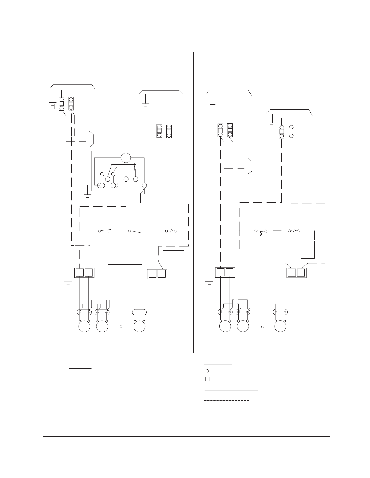
WIRING DIAGRAM - 380-400/1/50
GND
AIR DEFROST MODELS
WITH DEFROST TIME CLOCK
REFER TO EVAPORATOR
NAMEPLATE FOR ELECTRICAL
REQUIREMENTS
L2
L1
FUSE OR
CIRCUIT
GND
BREAKER
NOTE #3
TO MULTIPLE
EVAPORATORS
(IF APPLIC)
M1
M2
GND
PUMP DOWN
SWITCH
(IF USED)
3
1
2ND FUSE
OMITTED IF N
TM
4X
2
SPACE
THERMOSTAT
NOTE #4
CONTROL VOLTAGE
GND
FUSE OR
CIRCUIT
BREAKER
NOTE #3
N
SOLENOID VALVE
L1
L2(N)
LIQUID LINE
NOTE #4
N.C.
WITHOUT DEFROST TIME CLOCK
REFER TO EVAPORATOR
NAMEPLATE FOR ELECTRICAL
REQUIREMENTS
L2
L1
SPACE
NOTE #4
CONTROL VOLTAGE
L1
SOLENOID VALVE
GND
FUSE OR
CIRCUIT
BREAKER
NOTE #3
TO MULTIPLE
EVAPORATORS
(IF APPLIC)
M1
M2
THERMOSTAT
L2(N)
FUSE OR
CIRCUIT
BREAKER
NOTE #3
2ND FUSE
OMITTED IF N
LIQUID LINE
NOTE #4
N.C.
EVAPORATOR
M1
M2
TERMINAL BOARD
GND.
FAN
FAN
MTR
MTR
NOTES
1). USE COPPER CONDUCTORS ONLY
2). USE 90°C WIRE (OR HIGHER)
3). OVERCURRENT PROTECTION FOR
EVAPORATOR FAN MOTORS AND DEFROST
HEATERS MUST NOT EXCEED MAXIMUM
VALUE SHOWN ON EVAPORATOR NAMEPLATE.
4). MAY BE FACTORY INSTALLED-MOUNTED AND
WIRED ON EVAPORATOR .
2-MP AIR 460-575 10/05
4
FAN MOTOR
POWER
PLUGS
REFER TO
EVAPORATOR
FAN
MTR
DATA PLATE
FOR MOTOR
QUANTITY
EVAPORATOR
M2
N
M1
TERMINAL BOARD
GND.
N
4
FAN MOTOR
POWER
PLUGS
REFER TO
FAN
MTR
FAN
MTR
EVAPORATOR
FAN
MTR
DATA PLATE
FOR MOTOR
QUANTITY
TERMINALS
-COMPONENT TERMINAL
-TERMINAL BLOCK TERMINAL
CONDUCTORS/WIRING
FACTORY WIRING
WIRING BY OTHERS
OPTIONAL FACTORY OR
BY OTHERS
ALL FIELD WIRING MUST BE DONE IN
COMPLIANCE WITH ALL APPLICABLE LOCAL
AND NATIONAL CODES.
- 1 1 -
Page 12

WIRING DIAGRAM -
200-220/1/50, 380-400/1/50
ELECTRIC DEFROST MODELS -SINGLE EVAPORATOR
FOR ALL MODELS USING DEFROST HEATER CONTACTOR AND FAN CONTACTOR
REFER TO EVAPORATOR
DEFROST CLOCK
PARAGON # 8145
OR EQUIVALENT
TM
3
4X
21
EVAP FAN
L2
L1
T1
T2
CONTACTOR
M1
GND.
C
N
PUMP DOWN
SWITCH
(IF USED)
M2
4
X
BN
BK
KLIXON DEFROST TERMINATION
& FAN DELAY
DT-DEFROST TERM
FD-FAN DELAY
CONTROL VOLTAGE
GND
FUSE OR
CIRCUIT
BREAKER
NOTE #3
COMPR INTERLOCK
(IF USED)
SPACE
THERMOSTAT
NOTE #4
DT
FD
CONTROL
(10.0A MAX.)
C
RD
L1
L2(N)
N.C.
LIQUID LINE
SOL VALVE
NOTE #4
H1
DEFROST HEATERS
NAMEPLATE FOR ELECTRICAL
REQUIREMENTS
L2
L1
GND
FUSE OR
CIRCUIT
BREAKER
NOTE #3
DEFROST HEATER
L2
L1
C
T1
H2
T2
CONTACTOR
N
FANFAN
MTR
MTR
NOTES
1). USE COPPER CONDUCTORS ONLY
2). USE 90°C WIRE (OR HIGHER)
3). OVERCURRENT PROTECTION FOR
EVAPORATOR FAN MOTORS AND
DEFROST HEATERS MUST NOT EXCEED
MAXIMUM VALUE SHOWN ON
EVAPORATOR NAMEPLATE.
4.) MAY BE FACTORY INSTALLED-MOUNTED
AND WIRED ON EVAPORATOR
4A-MP ED 1 ph. ALL SINGLE 11/05
FAN
MTR
FAN MOTOR
POWER PLUGS
REFER TO
EVAPORATOR
DATA PLATE FOR
MOTOR QUANTITY
EVAPORATOR
TERMINALS
-COMPONENT TERMINAL
-TERMINAL BLOCK TERMINAL
CONDUCTORS/WIRING
FACTORY WIRING
WIRING BY OTHERS
OPTIONAL FACTORY
OR BY OTHERS
ALL FIELD WIRING MUST BE DONE IN
COMPLIANCE WITH ALL APPLICABLE LOCAL
AND NATIONAL CODES.
- 12 -
Page 13

WIRING DIAGRAM - 200-220/3/50
ELECTRIC DEFROST MODELS
WITHOUT FAN CONTACTOR
FOR ALL MODELS USING THREE PHASE DEFROST HEATER CONTACTOR
WITHOUT FAN CONTACTOR
REFER TO EVAPORATOR
DEFROST CLOCK
PARAGON # 8145
OR EQUIVALENT
TM
3
4X
21
N
COMPR INTERLOCK
PUMP DOWN
SWITCH
(IF USED)
FUSE OR
CIRCUIT
BREAKER
NOTE #3
(IF USED)
SPACE
THERMOSTAT
NOTE #4
N.C.
LIQUID LINE
SOL VALVE
NOTE #4
NAMEPLATE FOR ELECTRICAL
REQUIREMENTS
L3
L2
L1
GND
L1
C
T1
FUSE OR
CIRCUIT
BREAKER
NOTE #3
DEFROST HEATER
L2
L3
CONTACTOR
T2
T3
M2
M1
GND.
MTR
NOTES
1). USE COPPER CONDUCTORS ONLY
2). USE 90°C WIRE (OR HIGHER)
3). OVERCURRENT PROTECTION FOR
EVAPORATOR FAN MOTORS AND
DEFROST HEATERS MUST NOT EXCEED
MAXIMUM VALUE SHOWN ON
EVAPORATOR NAMEPLATE.
4.) MAY BE FACTORY INSTALLED-MOUNTED
AND WIRED ON EVAPORATOR
3-MP ED 230V single 10/05
4
X
BN
DT
BK
KLIXON DEFROST TERMINATION
FD
& FAN DELAY
CONTROL
(10.0A MAX.)
DT-DEFROST TERM
FD-FAN DELAY
FANFAN
MTR
C
FAN
MTR
RD
H1
DEFROST HEATERS
FAN MOTOR
POWER PLUGS
REFER TO
EVAPORATOR
DATA PLATE FOR
MOTOR QUANTITY
H2
H3
N
EVAPORATOR
TERMINALS
-COMPONENT TERMINAL
-TERMINAL BLOCK TERMINAL
CONDUCTORS/WIRING
FACTORY WIRING
WIRING BY OTHERS
OPTIONAL FACTORY
OR BY OTHERS
ALL FIELD WIRING MUST BE DONE IN
COMPLIANCE WITH ALL APPLICABLE LOCAL
AND NATIONAL CODES.
- 13 -
Page 14

WIRING DIAGRAM -
200-220/3/50, 380-400/3/50
ELECTRIC DEFROST MODELS - SINGLE EVAPORATOR
FOR ALL MODELS USING DEFROST HEATER CONTACTOR AND FAN CONTACTOR
REFER TO EVAPORATOR
DEFROST CLOCK
PARAGON # 8145
OR EQUIVALENT
TM
3
4X
21
EVAP FAN
L2
L1
T1
T2
CONTACTOR
C
N
PUMP DOWN
SWITCH
(IF USED)
CONTROL VOLTAGE
L1
GND
FUSE OR
CIRCUIT
BREAKER
NOTE #3
COMPR INTERLOCK
(IF USED)
SPACE
THERMOSTAT
NOTE #4
L2(N)
N.C.
LIQUID LINE
SO L VA LVE
NOTE #4
NAMEPLATE FOR ELECTRICAL
REQUIREMENTS
L2
L1
L3
GND
FUSE OR
CIRCUIT
BREAKER
NOTE #3
DEFROST HEATER
L2
L1
C
L3
CONTACTOR
T2
T1
T3
M1
M2
4
GND.
KLIXON DEFROST TERMINATION
MTR
NOTES
1). USE COPPER CONDUCTORS ONLY
2). USE 90°C WIRE (OR HIGHER)
3). OVERCURRENT PROTECTION FOR
EVAPORATOR FAN MOTORS AND
DEFROST HEATERS MUST NOT EXCEED
MAXIMUM VALUE SHOWN ON
EVAPORATOR NAMEPLATE.
4.) MAY BE FACTORY INSTALLED-MOUNTED
AND WIRED ON EVAPORATOR
4-MP ED ALL SINGLE 10/05
X
BN
DT
BK
FD
& FAN DELAY
CONTROL
(10.0A MAX.)
DT-DEFROST TERM
FD-FAN DELAY
FANFAN
MTR
C
FAN
MTR
RD
H1
DEFROST HEATERS
FAN MOTOR
POWER PLUGS
REFER TO
EVAPORATOR
DATA PLATE FOR
MOTOR QUANTITY
H2
EVAPORATOR
N
H3
TERMINALS
-COMPONENT TERMINAL
-TERMINAL BLOCK TERMINAL
CONDUCTORS/WIRING
FACTORY WIRING
WIRING BY OTHERS
OPTIONAL FACTORY
OR BY OTHERS
ALL FIELD WIRING MUST BE DONE IN
COMPLIANCE WITH ALL APPLICABLE LOCAL
AND NATIONAL CODES.
- 14 -
Page 15

WIRING DIAGRAM - 200-220/3/50, 380-400/3/50
ELECTRIC DEFROST MODELS -
MULTIPLE SINGLE PHASE EVAPORATORS
FOR ALL MODELS USING DEFROST HEATER CONTACTOR AND FAN CONTACTOR
REFER TO EVAPORATOR
DEFROST CLOCK
PARAGON # 8145
OR EQUIVALENT
TM
3
4
2
1
CONTROL VOLTAGE
L2(N)
L1
GND
FUSE OR
CIRCUIT
X
N
BREAKER
NOTE #3
COMPR INTERLOCK
(IF USED)
NAMEPLATE FOR ELECTRICAL
REQUIREMENTS
L2
L1
L3
GND
FUSE OR
CIRCUIT
BREAKER
NOTE #3
L2
L1
C
T1
L3
T2
T3
DEFROST HEATER
CONTACTOR
L3
L2
GND.
L1
C
T2
T1
M1
M2
MTR
EVAP FAN
CONTACTOR
T3
FUSE OR
CIRCUIT
BREAKER
NOTE #3
TO M1 & M2
2ND EVAP
4
X
BN
DT
BK
KLIXON DEFROST TERMINATION
FD
& FAN DELAY
CONTROL
(10.0A MAX.)
DT-DEFROST TERM
FD-FAN DELAY
FANFAN
MTR
C
RD
FAN
MTR
NOTES
1). USE COPPER CONDUCTORS ONLY
2). USE 90°C WIRE (OR HIGHER)
3). OVERCURRENT PROTECTION FOR
EVAPORATOR FAN MOTORS AND
DEFROST HEATERS MUST NOT EXCEED
MAXIMUM VALUE SHOWN ON
EVAPORATOR NAMEPLATE.
4.) MAY BE FACTORY INSTALLED-MOUNTED
AND WIRED ON EVAPORATOR
5A-MP ED 1ph. ALL MULTI 11/05
PUMP DOWN
SWITCH
(IF USED)
H1
DEFROST HEATERS
FAN MOTOR
POWER PLUGS
REFER TO
EVAPORATOR
DATA PLATE FOR
MOTOR QUANTITY
SPACE
THERMOSTAT
NOTE #4
H2
N.C.
LIQUID LINE
SOL VALVE
NOTE #4
N
PRIMARY
EVAPORATOR
FUSE OR
CIRCUIT
BREAKER
NOTE #3
*
H1
H2
M1
M2
KLIXON DEFROST TERMINATION
X
4
BN
DT
BK
FD
& FAN DELAY
CONTROL
N
GND.
C
RD
SECONDARY
EVAPORATOR
*FAN DELAY NOT USED ON 2ND EVAP.
TERMINALS
-COMPONENT TERMINAL
-TERMINAL BLOCK TERMINAL
CONDUCTORS/WIRING
FACTORY WIRING
WIRING BY OTHERS
OPTIONAL FACTORY
OR BY OTHERS
ALL FIELD WIRING MUST BE DONE IN
COMPLIANCE WITH ALL APPLICABLE LOCAL
AND NATIONAL CODES.
- 15 -
Page 16

WIRING DIAGRAM - 200-220/3/50, 380-400/3/50
ELECTRIC DEFROST MODELS -
MULTIPLE THREE PHASE EVAPORATORS
FOR ALL MODELS USING DEFROST HEATER CONTACTOR AND FAN CONTACTOR
REFER TO EVAPORATOR
DEFROST CLOCK
PARAGON # 8145
OR EQUIVALENT
TM
3
4X
21
EVAP FAN
L2
L1
T1
T2
CONTACTOR
FUSE OR
CIRCUIT
BREAKER
NOTE #3
TO M1 & M2
2ND EVAP
C
N
PUMP DOWN
SWITCH
(IF USED)
CONTROL VOLTAGE
L1
GND
FUSE OR
CIRCUIT
BREAKER
NOTE #3
COMPR INTERLOCK
(IF USED)
SPACE
THERMOSTAT
NOTE #4
LIQUID LINE
SOL VALVE
NOTE #4
L2(N)
N.C.
NAMEPLATE FOR ELECTRICAL
REQUIREMENTS
L2
L1
L3
GND
FUSE OR
CIRCUIT
BREAKER
NOTE #3
L2
L1
C
T1
T2
L3
T3
FUSE OR
CIRCUIT
NOTE #3
BREAKER
DEFROST HEATER
CONTACTOR
M2
M1
GND.
4
BN
KLIXON DEFROST TERMINATION
DT-DEFROST TERM
FD-FAN DELAY
FANFA N
MTR
MTR
X
DT
BK
FD
& FAN DELAY
CONTROL
(10.0A MAX.)
C
RD
FAN
MTR
NOTES
1). USE COPPER CONDUCTORS ONLY
2). USE 90°C WIRE (OR HIGHER)
3). OVERCURRENT PROTECTION FOR
EVAPORATOR FAN MOTORS AND
DEFROST HEATERS MUST NOT EXCEED
MAXIMUM VALUE SHOWN ON
EVAPORATOR NAMEPLATE.
4.) MAY BE FACTORY INSTALLED-MOUNTED
AND WIRED ON EVAPORATOR
5-MP ED ALL MULTI 10/05
H1
DEFROST HEATERS
FAN M OTOR
POWER PLUGS
REFER TO
EVAPORATOR
DATA PLATE FOR
MOTOR QUANTITY
H2
N
H3
PRIMARY
EVAPORATOR
*
M2
M1
4
KLIXON DEFROST TERMINATION
X
BN
BK
& FAN DELAY
H1
DT
FD
CONTROL
H3
H2
N
GND.
C
RD
SECONDARY
EVAPORATOR
*FAN DELAY NOT USED ON 2ND EVAP.
TERMINALS
-COMPONENT TERMINAL
-TERMINAL BLOCK TERMINAL
CONDUCTORS/WIRING
FACTORY WIRING
WIRING BY OTHERS
OPTIONAL FACTORY
OR BY OTHERS
ALL FIELD WIRING MUST BE DONE IN
COMPLIANCE WITH ALL APPLICABLE LOCAL
AND NATIONAL CODES.
- 16 -
Page 17

WIRING DIAGRAM -
200-220/1/50
HOT GAS DEFROST MODELS
USING MAXIMUM 15A HEATER OVERCURRENT PROTECTION
REFER TO EVAPORATOR
NAMEPLATE FOR ELECTRICAL
REQUIREMENTS
L2(N)
L1
GND
FUSE OR
CIRCUIT
BREAKER
REFER TO SPECIFIC SYSTEM WIRING DIAGRAM
(BY OTHERS) FOR FIELD CONTROL WIRING
230v CONTROL VOLTAGE SHOWN
15A
FAN MOTOR / HEATER WIRING
H1
BN
C
DRAIN PAN HEATER
RD
FAN MOTOR
POWER PLUGS
REFER TO
EVAPORATOR
FAN
DATA PLATE FOR
MTR
MOTOR QUANTITY
GND.
M1
M2
MTR
F
X
BK
*FAN HEATER
CONTROL
RD
**DEFROST TERMINATION
CONTROL
FANFAN
MTR
3
NOTES
1). USE COPPER CONDUCTORS ONLY
2). USE 90°C WIRE (OR HIGHER)
3). OVERCURRENT PROTECTION FOR
EVAPORATOR FAN MOTORS AND
DEFROST HEATERS MUST NOT EXCEED
MAXIMUM VALUE SHOWN ON
EVAPORATOR NAMEPLATE.
4.) MAY BE FACTORY INSTALLED-MOUNTED
AND WIRED ON EVAPORATOR
6-MP HG 230V 11/05
(IF APPLICABLE)
RD
EVAPORATOR
H2
N
*FAN HEATER
CONTROL
ON REVERSE CYCLE LOCATED AT SUCTION LINE.
ON THREE-PIPE LOCATED AT DISTRIBUTOR SIDE PORT.
NOTE: DURING THE HOT GAS DEFROST CYCLE
THE FAN/HEATER CONTROL DE-ENERGIZES THE
EVAPORATOR FANS AND ENERGIZES THE
DRAIN PAN HEATER.
(ANYTIME THE TEMPERATURE OF THE INCOMING
REFRIGERANT GAS IS ABOVE 50° F).
**DEFROST TERMINATION
CONTROL
OPTIONAL FACTORY WIRED OR BY OTHERS
LOCATED ON TUBE END SHEET
THE CONTROL CLOSES WHEN REACHES 55` F
TERMINALS
-COMPONENT TERMINAL
-TERMINAL BLOCK TERMINAL
CONDUCTORS/WIRING
FACTORY WIRING
WIRING BY OTHERS
OPTIONAL FACTORY
OR BY OTHERS
ALL FIELD WIRING MUST BE DONE IN
COMPLIANCE WITH ALL APPLICABLE LOCAL
AND NATIONAL CODES.
- 17 -
Page 18

WIRING DIAGRAM -
380-400/1/50
HOT GAS DEFROST MODELS
USING FAN CONTACTOR ( AND HEATER CONTACTOR IF APPLIC)
REFER TO EVAPORATOR
NAMEPLATE FOR ELECTRICAL
REQUIREMENTS
FUSE OR
CIRCUIT
BREAKER
GND
L2
L1
GND.
EVAP FAN
L2
L1
C
F
M2
M1
MTR
X
3
BK
*FAN HEATER
CONTROL
RD
**DEFROST TERMINATION
CONTROL
FANFAN
MTR
CONTACTOR
T2
T1
H1
BN
C
DRAIN PAN HEATER
RD
(IF APPLICABLE)
FAN MO TOR
POWER PLUGS
REFER TO
EVAPORATOR
FAN
DATA PLATE FOR
MTR
MOTOR QUANTITY
C
H2
RD
EVAPORATOR
L2
L1
T2
T1
DEFROST HEATER
CONTACTOR
(IF APPLIC)
REFER TO SPECIFIC SYSTEM WIRING DIAGRAM
(BY OTHERS) FOR FIELD CONTROL WIRING
N
*FAN HEATER
CONTROL
ON REVERSE CYCLE LOCATED AT SUCTION LINE.
ON THREE-PIPE LOCATED AT DISTRIBUTOR SIDE PORT.
NOTE: DURING THE HOT GAS DEFROST CYCLE
THE FAN/HEATER CONTROL DE-ENERGIZES THE
EVAPORATOR FANS AND ENERGIZES THE
DRAIN PAN HEATER.
(ANYTIME THE TEMPERATURE OF THE INCOMING
REFRIGERANT GAS IS ABOVE 50° F).
**DEFROST TERMINATION
CONTROL
OPTIONAL FACTORY WIRED OR BY OTHERS
LOCATED ON TUBE END SHEET
THE CONTROL CLOSES WHEN REACHES 55` F (20 F DIFF)
NOTES
1). USE COPPER CONDUCTORS ONLY
2). USE 90°C WIRE (OR HIGHER)
3). OVERCURRENT PROTECTION FOR
EVAPORATOR FAN MOTORS AND
DEFROST HEATERS MUST NOT EXCEED
MAXIMUM VALUE SHOWN ON
EVAPORATOR NAMEPLATE.
4.) MAY BE FACTORY INSTALLED-MOUNTED
AND WIRED ON EVAPORATOR
7-MP ALL HG 11/05
- 18 -
TERMINALS
-COMPONENT TERMINAL
-TERMINAL BLOCK TERMINAL
CONDUCTORS/WIRING
FACTORY WIRING
WIRING BY OTHERS
OPTIONAL FACTORY
OR BY OTHERS
ALL FIELD WIRING MUST BE DONE IN
COMPLIANCE WITH ALL APPLICABLE LOCAL
AND NATIONAL CODES.
Page 19

(425)
16 3/4
MTG SLOTS
(425)
16 3/4
MTG SLOTS
8 1/8
(206)
PIPING
8 1/8
(206)
PIPING
COMPARTMENT
COMPARTMENT
50 1/4
(1276)
36
(914)
1 FAN MODEL
TOP VIEW
34
(864)
DIMENSIONAL DATA
6 1/8
(156)
(704)
27 3/4
ELECTRICAL
COMPARTMENT
3/4 NPT ( 14 NPS )
DRAIN CONNECTION
24
(608)
MINIMUM CLEARANCE
84 1/4
(2140)
6 1/8
(156)
ELECTRICAL
COMPARTMENT
2 FAN MODEL
TOP VIEW
36
(914)
11 7 /8
(302)
(387)
ALL MODELS
AIR THROW :
APPROX. 75 FEET
(23 METERS)
IN OPEN SPACE
5 3/4
15
(144)
(425)
16 3/4
MTG SLOTS
(425)
16 3/4
MTG SLOTS
8 1/8
(206)
PIPING
COMPARTMENT
8 1/8
(206)
PIPING
COMPARTMENT
(864)
30
(762)
118 1/ 4
(3004)
34
34
(864)
36
(914)
6 1/8
(156)
3 FAN MODEL
TOP VIEW
ELECTRICAL
COMPARTMENT
136 1/4
(3461)
30
(762)
30
(762)
32
(813)
6 1/8
(156)
4 FAN MODEL
TOP VIEW
ELECTRICAL
COMPARTMENT
- 19 -
Page 20

DIMENSIONAL DATA/SPECIFICATIONS
Medium Temperature Air and Electric Defrost Models
LEDOMSNAFFO.ONTAEWS)DI(NOITCENNOCNOITCUS EZISTELNIROTUBIRTSID
#M811
#M221
#M822
#M632
#M542
#M553
#M863
#M084
#M884
Low Temperature Electric Defrost Models
LEDOMSNAFFO.ONTAEWS)DI(NOITCENNOCNOITCUS EZISTELNIROTUBIRTSID
EL611
EL911
EL522
EL232
EL042
EL843
EL653
EL174
EV311
EV711
EV222
EV822
EV432
EV933
EV053
EV954
18/78/5
18/118/5
28/118/5
28/318/5
28/318/7
38/518/7
38/518/7
48/518/7
48/518/7
sliatedroferutalcnemoNotrefeR.EroA=#
18/118/5
18/118/5
28/318/5
28/318/
28/518/7
38/518/7
38/518/11
48/128/11
18/118/5
18/118/5
28/318/5
28/318/7
28/518/
38/518/7
38/518/7
48/518/11
7
7
Hot Gas Defrost Models
LEDOM
^M811
^M221
^M822
^M632
^M542
^M553
^M863
^M084
^M884
^
L611
^L911
^L522
^L232
^L042
^L
843
^L653
^L174
^V311
^V711
^V222
^V822
^V432
^V933
^V053
^V954
.ON
FO
SNAF
18/78/52/18/52/18/7
18/118/72/18/72/18/7
28/118/72/18/72/18/7
28/318/72/18/72/18/7
28/318
38/518/118/58/118/58/11
38/518/318/78/318/78/11
48/518/318/78/518/78/31
48/518/318/78/518/78/31
18/118/72/18/72/18/7
18/118/72/18/72/18/7
28/318/72/18/118/58/7
28/318/118/58/318/78/7
28/518/318/78/318/78/7
38/518/518/118/518/118/11
38/518/518/118/518/118/11
48/128/518/118/518/118/31
18/118/72/18/72/18/7
18/118/72/
28/318/72/18/118/58/7
28/318/118/58/118/58/7
28/518/318/78/318/78/7
38/518/118/58/318/78/11
38/518/
48/518/518/118/518/118/31
NOITCUS
NOITCENNOC
TAEWS)DI(
ROTUBIRTSID
TELNI
TAEWS)DO(EZIS
/118/58/118/58/7
318/78/518/78/11
sliatedroferutalcnemoNotrefeR.Rro,G,H,T=^
TSORFEDELCYCESREVERTSORFEDEPIP3
TROPEDIS
NOITCENNOC
TAEWS)DO(
18/72/18/7
ROTUBIRTSID
TELNI
TAEWS)DO(EZIS
TROPEDIS
NO
ITCENNOC
TAEWS)DO(
- 20 -
NAPNIARDSAGTOH
NOITCENNOCPOOL
TAEWS)DO(
Page 21

SHIPPING WEIGHTS
TSORFEDRIATSORFEDCIRTCELE TSORFEDSAGTOH
LEDOM
#
AM811
AM221
AM822
AM632
AM542
AM553
AM863
AM084
A
M884
GNIPPIHS
THGIEW
.BL
451
161
422
042
452
623
943
414
334
).gk(
)07(
)37(
)201(
)901(
)511(
)841(
)851(
)881(
)691(
LEDOM
#
EM811
E
M221
EM822
EM632
EM542
EM553
EM863
3
EM084
EM884
EL611
EL911
EL522
EL232
EL042
EL843
EL653
EL174
EV311
EV711
EV222
EV822
EV432
EV933
EV
053
EV954
GNIPPIHS
THGIEW
.BL
361
171
142
752
072
943
27
144
064
461
171
342
752
372
253
773
344
061
661
832
052
362
643
263
524
).gk(
)47(
)77(
)901(
)611(
)321(
)851(
)961(
)002(
)902(
)47(
)87(
)011(
)711(
)421(
)061(
)171(
)102(
)37(
)57(
)801(
)311(
)911(
)751(
)461(
)391(
843RL843
#LEDOM
HM811RM811
HM221RM221
HM822RM822
HM632RM632
HM542RM542
HM553RM553
HM863RM863
HM084RM084
HM884RM884
HL611RL611
HL911RL911
HL522RL522
HL232RL232
HL042RL042
HL
HL653RL653
HL174RL174
HV311RV311
HV711RV711
HV222RV222
HV822RV822
HV432RV432
HV933RV933
HV053RV053
HV954RV954
POOLSAGTOHHTIWNAPRETAEHCI
THGIEWGNIPPIHS
.BL
061
861
932
552
962
353
673
354
274
161
861
142
652
272
653
283
554
751
361
632
942
262
053
763
834
).gk(
)27(
)67(
)801(
)611(
)
221(
)061(
)071(
)502(
)412(
)37(
)67(
)901(
)611(
)321(
)261(
)371(
)602(
)17(
)47(
)701(
)311(
)911(
)951(
)661(
)891(
GM811TM811
GM221TM221
GM822TM822
GM632TM632
GM542TM542
GM553TM553
GM863TM863
GM084TM084
GM884TM884
GL611TL611
GL911TL911
GL522TL522
GL232TL232
GL042TL042
GL843TL843
GL653TL653
GL174TL174
GV311TV311
GV71
1TV711
GV222TV222
GV822TV822
GV432TV432
GV933TV933
GV053TV053
GV954TV954
RTCELEHTIW
#LEDOM
.BL
651
461
822
442
852
233
553
124
044
751
461
032
542
162
533
063
324
351
061
622
832
252
923
643
604
THGIEWGNIPPIHS
).gk(
)17(
)47(
)40
1(
)111(
)711(
)051(
)161(
)191(
)002(
)1
7(
)57(
)401(
)111(
)911(
)251(
)461(
)291(
)07(
)27(
)201(
)801(
)411(
)941(
)751(
)481(
GLYCOL FLUID AIR COOLER DATA
50Hz
.ON
LEDOM
FO
SNAF
W811
10682
W221
10962
W632
20275
W542
20045
W553
30858
W863
30908
W084
400801
WOLFRIA
MFC
0283(
H/UTB
)S/L(
0538
)0531(
0569
)0721(
00341
)0072(
00861
)0552(
00291
)0504(
00422
)
00752
)0115(
The above capacities were rated based on 30% Propylene Glycol, 25°F (-4°C) glycol entering temperature and 35°F (2°C) air entering termperature
with glycol flow rate listed. For all other conditions, please use "Pi-Coil" software (contact factory).
MPGSU51-*YTICAPAC )S/L590.( GNIBUT"8/3,MPGSU04-*YTICAPAC )S/L52.( GNIBUT"2/1,
TAW(
H.TF(
2
8.4
)0542(
8.2
)0382(
1.8
)0024(
8.4
)0494(
)0365(
)0856(
)0557(
1.11
7.6
6.7
.D.P
)ST
.D.P
)0
)aPk(
)3.41(
)4.8(
)2.42(
)3.41(
)2.33(
)0.02(
)7.22(
.NNOC
EZIS
)TUO/NI(
8/310362
8/310842
8/310525
8/310894
8/310097
8/310447
8/3106
99
WOLFRIA
MFC
H/UTB
)S/L(
00201
)0421(
00911
)0711(
00102
)0842(
00112
)0532(
00792
)0373(
00392
)0153(
00843
)0074(
)STTAW(
)0003(
)0053(
)0095(
)0026(
)0078(
)0068(
)00201(
-21 -
.D.P
H.TF(
2
8.7
6.4
31
4.7
71
01
21
.D.P
)0
)aPk(
)3.32(
)7.31(
)4.73(
)1.22(
)7.15(
)1.13(
)3.53(
.NNOC
EZIS
8/51
8/51
8/51
8/51
8/51
8/51
8/51
)TUO/NI(
Page 22

FACTORY INSTALLED DISTRIBUTOR NOZZLES
Note: For Hot Gas Defrost models only . Air and Electric Defrost models use V enturi distributors and no nozzle is required.
Medium Temperature
Reverse Cycle Defrost Models
LEDOM
TM811HM811
TM221HM221
TM822HM822
TM632HM632
TM542HM542
TM553HM553
TM863HM863
TM084HM084
TM884HM884
/A404R
705R
2/11-J1-J2-J
2-G2/11-G2-G
2/12-G2/11-G2/12-G
3-G2-G3-G
4-E2/1-2-E4-E
5-E3-E5-E
6-C4-C6-C
8-C5-C01-C
01-C5-C01-C
22Ra431R
Low Temperature
Reverse Cycle Defrost Models
LEDOM705R/A404R
TL611HL611
TL911HL911
TL522HL522
TL232HL232
TL042HL042
TL843HL843
TL653HL653
TL174HL174
2/1-2-G
3-G
4-G
5-E
6-C
8-A
-A
01
21-A
Medium Temperature
3 Pipe Defrost Models
LEDOM
GM811RM811
GM221RM221
GM822RM822
GM632RM632
GM542RM542
GM553RM553
GM863RM863
GM084RM084
GM884RM884
/A404R
705R
2/11-J1-J2-J
2-G2/11-G2-G
2/12-G2/11-G2/12-G
3-G2-G3-G
4-E2/1-2-E4-E
5-E3-E5-E
6-C4-C6-C
8-A5-C01-C
01-A5-C01-C
Low Temperature
3 Pipe Defrost Models
LEDOM705R/A404R
GL611RL611
GL911RL911
GL522RL522
GL232RL232
GL042RL042
GL843RL843
GL653RL653
GL174RL174
2/1-2-G
3-G
4-E
5-C
6-C
8-A
-A
01
21-A
22Ra431R
TV311HV311
TV711HV711
TV222HV222
TV822HV822
TV432HV432
TV933HV933
TV053HV053
TV954HV954
LEDOM705R/A404R
LEDOM705R/A404R
2-G
2/1-2-G
3-G
4-E
5-C
6-E
C
8-
01-A
GV311RV311
GV711RV711
GV222RV222
GV822RV822
GV432RV432
GV933RV933
GV053RV053
GV954RV954
2-G
2/1-2-G
3-E
4-E
5-C
6-C
A
8-
01-A
- 22 -
Page 23

RECOMMENDED THERMAL EXPANSION VALVE SELECTIONS
MEDIUM TEMPERATURE MODELS
DANFOSS
LEDOM705R/A404R22Ra431R
M811
M221
M822
M632
M542
M553
M863
M084
M
884
70-EAUT60-EAUT70-EAUT
80-EAUT70-EAUT80-EAUT
90-EAUT80-EAUT90-EAUT
90-EAUT80
2-EACT90-EAUT2-EACT
3-EACT1-EACT3-EACT
8.5SBEDT2-EACT5.8NBEDT
0.8SBEDT3-EACT6.9NBEDT
0.8SBEDT3-EACT6.9NBEDT
-EAUT90-EAUT
ALCO
LEDOM705R/A404R22Ra431R
M811
M221
M822
M632
M542
M553
M863
M084
M884
Above selections based on:
1) 100°F (38°C) vapor free liquid entering expansion valve
2) 110°F (43°C) Condensing temperature
3) 8 -12°F (4.4 -6.7°C) evaporator TD
CS-4/1-1-CSEFHCH-2/1-1-CSEFHCM-2/1-1-CSEFH
CS-2/1-1-CSEFHCH-2-CSEFHCM-4/3-1-CS
CS-2-CSEFHCH-2-CSEFHCM-4/3-1-CSEFH
CS-2/1-3-CSEFHCH-2/1-2-CSEFHCM-2/1-2-CSEFH
CS-2/1-3-CSEFHC
CS-2/1-3-CSEFHCH-2/1-5-CSEFHCM-4-CSEFH
CS-5-CSEFHCH-2/1-5-CSEFHCM-6-CSEFH
CS-
7-CSEFHCH-2/1-5-CSEFHCM-6-CSEFH
CS-7-CSEFHCH-8-CSEFHCM-2/1-7-CSEFH
H-3-CSEFHCM-4-CSEFH
SPORLAN*
LEDOM705R/A404R22Ra431R
M811
M221
M822
M632
M542
M553
M863
M084
M884
EFH
SC-5-EVSC-5-EJS
fer,705RroF*
C-2/11-ESGEC-2/1-1-EVGEC-1-EJGE
C-2/11-ESGEC-2/1-1-EVGEC-2/11-EJGE
C-2-ESGEC
C-3-ESSC-3-EVGEC-2/12-EJS
C-4-ESSC-3-EVGEC-3-EJS
C-4-ESSC-4-EVSC-3-EJS
C-6-ES
C-7-ESSC-5-EVSC-6-EJS
C-7-ESSC-8-EVSC-6-EJS
ELZZON
2/1070.
4/3680.
15990.
2/1-1021.
26041.
2/1-2751.
3271.
4991.
5112.
6242.
8662.
01182.
-2-EVGEC-2/11-EJGE
""EPGE""semoceb""ESGE"":.e.i.""S""fodaetsni""P""
trahcgniwollofeht
.
oNECIFIRO
.NI
gnisudleifehtnidellirdebnacezisecifiro
EZISLLIRD
eblliwevlavnoisnapxenalropSrofedoctnaregir
reporpeht,elbaliavatonsielzzontcerrocfI
- 23 -
Page 24

RECOMMENDED THERMAL EXPANSION VALVE SELECTIONS
LOW TEMPERATURE R404A/R507* MODELS
DANFOSS
LEDOMF°0 )C°81-( .PAVEF°01- )C°32-( .PAVEF°02- )C°92-( .PAVEF°03- )C°43-( .PAVEF°04- )C°04-( .PAVE
L611
L911
L522
L232
L042
L843
L653
L174
V311
V711
V222
V822
V432
V933
V053
V954
SPORLAN*
LEDOMF°0 )C°81-( .PAVEF°01- )C°32-( .PAVEF°02- )C°92-( .PAVEF°03- )C°43-( .PAVEF°04- )C°04-( .PAVE
L611
L911
L522
L232
L042
L843
L653
L174
V311
V711
V222
V822
V432
V933
V053
V954
80-EAUT90-EAUT90
90-EAUT90-EAUT1-EACT1-EACT1-EACT
1-EACT1-EACT2-EACT2-EACT2-EACT
2-EACT2-EACT2-EACT3-EA
3-EACT3-EACT3-EACT8.5SBEDT8.5SBEDT
3-EACT8.5SBEDT8.5SBEDT0.8SBEDT0.8SBEDT
8.5SBEDT0.8SBEDT0.8S
0.8SBEDT1.9SBEDT7.11SBEDT7.11SBEDT7.11SBEDT
80-EAUT80-EAUT80-EAUT90-EAUT90-EAUT
8
0-EAUT90-EAUT90-EAUT90-EAUT1-EACT
90-EAUT1-EACT1-EACT1-EACT2-EACT
1-EACT2-EACT2-EACT2-EACT3-EACT
2-EACT23-EACT3-EACT3-EACT8.5SBEDT8.5SBEDT
5.5SEDT8.5SBEDT0.8SBEDT0.8SBEDT0.8SBEDT
8.5SB
EDT0.8SBEDT0.8SBEDT1.9SBEDT1.9SBEDT
C-1-ESGEPZ-2/11
C-2/11-ESGEPZ-2/11-ESGEPZ-2-ESGEPZ-2-ESGEPZ-2-ESGE
C-2-ESGEPZ-2C-3-ESSPZ-3-ESSPZ-4-ESSPZ-4-ESSPZ-4-ESS
C-4-ESSPZ-4-ESSPZ-4-ESSPZ-6-ESSPZ-6-E
C-4-ESSPZ-6-ESSPZ-6-ESSPZ-7-ESSPZ-7-ESS
C-6-ESSPZ-6-ESSPZ-7-ESSPZ-7-ESSPZ-9-ESO
C-7-ESSPZ-7-ESSPZ-9
C-1-ESGEPZ-1-ESGEPZ-1-ESGEPZ-2/11-ESGEPZ-2/11-ESGE
C-2/11-ESGEPZ-2/11-ESGEPZ-2/1
C-2-ESGEPZ-2-ESGEPZ-2-ESGEPZ-2-ESGEPZ-3-ESS
C-2-ESGEPZ-3-ESSPZ-3-ESSPZ-3-ESSPZ-3
C-3-ESSPZ-3-ESSPZ-4-ESSPZ-4-ESSPZ-4-ESS
C-4-ESSPZ-4-ESSPZ-4-ESSPZ-4-ESSPZ-6-ESS
C-4-ESSPZ-6-ESSPZ
C-6-ESSPZ-6-ESSPZ-7-ESSPZ-9-ESOPZ-9-ESO
EACT3-EACT3-EACT3-EACT
-ESGEPZ-2/11-ESGEPZ-2/11-ESGEPZ-2-ESGE
ESGEPZ-3-ESSPZ-3-ESSPZ-3-ESS
i""P""eblliwevlavnoisnapxenalropSrofedoctnaregirfer,705RroF*
-EAUT90-EAUT1-EACT
CT3-EACT
BEDT0.8SBEDT0.8SBEDT
-ESOPZ-21-ESOPZ-21-ESO
1-ESGEPZ-2-ESGEPZ-2-ESGE
-6-ESSPZ-7-ESSPZ-7-ESS
""EPGE""semoceb""ESGE"":.e.i.""S""fodaetsn
SS
-ESS
Above selections based on:
1) 100°F (38°C) vapor free liquid entering expansion valve
2) 110°F (43°C) Condensing temperature
3) 8 -12°F (4.4 -6.7°C) evaporator TD
- 24 -
Page 25

RECOMMENDED EXPANSION VALVE SELECTIONS
LOW TEMPERATURE R404A/7507 MODELS (CONT’D)
ALCO
LEDOMF°0 )C°81-( .PAVEF°01- )C°32-( .PAVEF°02- )C°92-( .PAVEF°03- )C°43-( .PAVEF°04- )C°04-( .PAVE
L611
L911
L522
L232
L042
L843
L653
L174
V311
V711
V222
V822
V432
V933
V053
V954
Above selections based on:
1) 100°F (38°C) vapor free liquid entering expansion valve
2) 110°F (43°C) Condensing temperature
3) 8 -12°F (4.4 -6.7°C) evaporator TD
CS-4/1-1-CSEFH5
CS-2/1-1-CSEFH53WS-2/1-1-CSEFH53WS-2-CSEFH54WS-2-CSE
CS-2-CSEFH53WS-2-CSEFH53WS-2/1-3-CSEFH54WS-2/1-3-CSEFH54WS-2/1-3-CSEFH
CS-2-CSEFH5
CS-2/1-3-CSEFH53WS-2/1-3-CSEFH53WS-5-CSEFH54
CS-2/1-3-CSEFH53WS-5-CSEFH53WS-5-CSEFH54WS-7-CSEFH54WS-7-CSEFH
CS-2/1-3-CSEFH5
CS-5-CSEFH53WS-7-CSEFH53WS-01-CSEFH54WS-01-CSEFH54WS-31CS-1-CSEFH53WS-4/1-1-CSEFH53WS-2/1-1-CSEFH54WS-2/1-1-CSEFH54WS-2-CSEFH
CS-4/1-1-CSEFH53WS-2/1-
CS-2/1-1-CSEFH53WS-2-CSEFH53WS-2-CSEFH54WS-2/1-3-CSEFH54W
CS-2-CSEFH53WS-2-CSEFH53WS-2/1-3-CSEFH54WS-2/1-3-CSEFH54WS-2/1-3-CSEFH
CS-2/1-3-CSEFH5
CS-2/1-3-CSEFH53WS-2/1-3-CSEFH53WS-5-CSEFH54WS-5
CS-2/1-3-CSEFH53WS-5-CSEFH53WS-5-CSEFH54WS-7-CSEFH54WS-7-CSEFH
CS-5-CSEFH53WS-5-CS
1-CSEFH53WS-2-CSEFH54WS-2-CSEFH54WS-2/1-3-CSEFH
EFH53WS-7-CSEFH54WS-01-CSEFH54WS-01-CSEFH
4WS-2/1-1-CSEFH53WS-2-CSEFH54WS-2-CSEFH54WS-2-CSEFH
FH54WS-2/1-3-CSEFH
3WS-2/1-3-CSEFH53WS-2/1-3-CSEFH54WS-2/1-3-CSEFH54WS-5-CSEFH
WS-5-CSEFH54WS-5-CSEFH
3WS-5-CSEFH53WS-7-CSEFH54WS-7-CSEFH54WS-01-CSEFH
CSEFH
S-2/1-3-CSEFH
3WS-2/1-3-CSEFH53WS-2/1-3-CSEFH54WS-5-CSEFH54WS-5-CSEFH
-CSEFH54WS-5-CSEFH
- 25 -
Page 26

INSTALLATION INSTRUCTIONS
INSTALLATION
The installation and start-up of Unit Coolers should only
be performed by qualified refrigeration mechanics.
This equipment should be installed in accordance with all
applicable codes, ordinances and local by-laws.
INSPECTION
Inspect all equipment before unpacking for visible signs of
damage or loss. Check shipping list against material
received to ensure shipment is complete.
IMPORTANT: Remember, you, the consignee, must make
any claim necessary against the transportation company .
Shipping damage or missing parts, when discovered at
the outset, will prevent later unnecessary and costly
delays.
If damage or loss during transport is evident, make
claim to carrier, as this will be their responsibility,
not the manufacturer’s.
Should carton be damaged, but damage to equipment is
not obvious, a claim should be filed for “concealed
damage” with the carrier.
IMPORTANT: The electrical characteristics of the unit
should be checked at this time to make sure they
correspond to those ordered and to electrical power
available at the job site.
Save all shipping papers, tags and instruction sheets for
reference by installer and owner .
APPLICATION
MP unit coolers are designed for walk-in cooler , walk-in
refrigerated warehouse and food processing plant applications used with refrigerant R22 or R404A. For room
temperatures above 35°F (2°C) AND evaporating temperatures above 26°F (-3°C), positive defrosting means (with
electric or hot gas) may not be required, otherwise,
electric defrost or hot gas defrost models should be used.
Electric defrost models come with defrost termination and
fan delay as standard to control the defrost cycle termination and fan delay , while defrost initiation means (e.g.
defrost timer) is not included.
For other types of refrigerant, contact factory .
The coil must not be exposed to any abnormal
atmospheric or acidic environments. This may result in
corrosion to the cabinet and possible coil failure (leaks).
(Consult manufacturer for optional baked on phenolic
protective coatings).
LOCATION
The unit location in the room should be selected to ensure
uniform air distribution throughout the entire space to be
refrigerated. Be sure that the product does not obstruct
the free circulation of air. Allow a minimum of 24” clearance at each end. Do not locate evaporators over doors.
Consideration should be given to the coil location in order
to minimize the piping run length to the
condensing unit and floor drain.
EXPANSION VALVE (TXV) SELECTION
All units require the use of an externally equalized
expansion valve. (A 1/4” (6 mm) O.D. equalizer line has
been provided on the coil) TX valves should not be
selected strictly by their nominal ton rating. (This rating
is based at a specific pressure differential and entering
liquid temperature). Since applications will differ it is
suggested the following selection procedure be followed.
1.Determine actual unit cooler capacity .
The nominal rating is based at 10
(Entering Air T emp. minus Evap. T emp.), R404A
refrigerant. For R22, use the rated capacity x 0.95.
For medium temperature R134a, use the rated
capacity x 0.90. Note that a higher / lower operating
T.D.will increase / decrease this capacity rating by
their direct ratio within a range of 8 to 12°F (4.4 to
6.7°C) T .D.
2.Determine the pressure drop across the valve by
subtracting the evaporating pressure and distributor
pressure drop from the high side liquid pressure.
The distributor pressure drop is typically in the range
of 20 to 35 psig (1.4 to 2.4 bar) depending on the type
of refrigerant and operating conditions.
3.Estimate entering liquid temperature. T emperatures
lower than 100°F (38 °C) increase valve capacity
ratings. Refer to valve manufacturer’s specs for
details.
4.Select valve from the valve manufacturer selection
charts or software for the appropriate refrigerant,
evaporating tempand pressure drop.
For best performance, the outlet of the expansion valve
should be installed directly to the distributor body . If this
is not possible, a straight tube up to 12 inches may be
used for the connection.
Locate the expansion valve bulb on a horizontal length
of suction line preferably 3 to 6 inches from the suction
header. Locate the bulb at 4 or 8 clock position and
insulate with a waterproof type of insulation. Clamp the
bulb to ensure 100% contact of the bulb with the
suction line.
For hot gas defrost models, ensure appropriate nozzle
has been installed in the distributor before installing
valve. After following the manufacturer’s installation
instructions and after the room has reached the desired
temperature the valve superheat should be checked.
This will confirm that the evaporator is operating
properly and performing to maximum efficiency . The
superheat should be around 60 to 80% of T .D. T oo high
or low a super heat will result in unsatisfactory system
performance and possible compressor problems.
O
F T .D. (5 .6°C)
- 26 -
Page 27

INSTALLATION INSTRUCTIONS
NOZZLE INSTALLATION
All air defrost and electric defrost models use venturi
distributors and no nozzles required. For hot gas defrost
models, a nozzle has been pre-selected and factory
installed for common applications (Medium temp. R404A,
R22, 8 to 12°F (4.4 to 6.7°C) T.D.; low temp. R404A, 8 to
12°F (4 .4 to 6.7°C) T.D.). For other applications, refer to
the nozzle manufacturer for selection method. When
replacing a nozzle, the nozzle retainer clip (in distributor)
must be removed before inserting nozzle. Re-install clip
ensuring nozzle is properly in place. A small nozzle can
be drilled larger using the drill size listed in table on page
25. Ensure the hole must be accurately centered and
smooth. A lathe is preferred for the drilling.
MOUNTING
Refer to dimensional drawing for recommended mounting
arrangements. Ensure adequate clearance is provided
behind the coil as well as each end. The evaporators may
be mounted flush with ceiling with bolts, or hanging down
with rod hangers. When using rod hangers, allow adequate space between the top of the unit and the ceiling
for cleaning to comply with NSF Standard 7.
Ensure that the ceiling is level since the drain pan
has been sloped for drainage during the defrost
cycle.
DRAIN LINE
The drain line should be run from the drain connection,
sloping at least 1” (25 mm) per foot and should have the
size at least as large as the drain connection. A trap in a
warm area outside the room must be provided to allow
proper draining through the tubing. Connection should be
made to proper drainage facilities that comply with local
regulations.
T o prevent freeze-up when the temperature of the
refrigerated space is 35oF (2 °C) or lower , the drain line
should be heated along its run inside the cold room. The
heated drain line should be insulated. It is recommended
that the heater be energized at all times. A heat input of
20 watts per foot in a 28°F (-2°C) room and 30 watts per
foot for -20°F (-29°C) rooms, is satisfactory. Drain line
heaters are not required for constant room temperature
above 35°F (2°C).
Always trap evaporator drain line individually to prevent
vapor migration.
Ensure that the drain line has sufficient slope for
proper drainage (prevention of ice build up/blockage
in pan).
PIPING
Refrigeration grade piping must be used for all field
refrigeration piping. Refrigerant line sizes are important
and may not be the same size as the coil connections.
Consult ASHRAE handbook or other similar reference
book for proper line sizing.
Refrigerant piping and control system should be designed
to prevent possible liquid slugging (from oil or refrigerant)
of the compressors on start-up after the defrost cycle.
Also, it should prevent oil logging and minimize refrigerant
pressure drop.
For hot gas models, see pages 29 to 30 for
recommended piping.
- 27 -
Page 28

INSTALLATION INSTRUCTIONS
WIRING
Wire system in accordance with governing standards and
local codes. See data and wiring diagrams on pages 4 to
21 for typical wiring arrangement. Electrical wiring is to be
sized in accordance with minimum circuit ampacity rating
(MCA). Size fuses used must not exceed the Maximum
Fuse Size ratings.
For ease of identifying the proper wiring terminal, unit
wiring is color coded and terminal block connections are
identified.
When fan delay thermostats (combination fan delay and
defrost termination) are installed, on start-up, the fans do
not operate until the coil temperature is reduced to
approximately 25oF (-4°C). It is normal for the fans to
cycle a few times until the room temperature is brought
down. At higher evaporating temperatures this control may
not close and therefore should either be by-passed
temporarily or replaced with an adjustable type. (set for a
higher temperature cut-in point).
MAINTENANCE
The unit should be periodically inspected for any dirt or ice
build-up on the fin surface and cleaned if necessary with a
soft whisk or brush. Also ensure coils inner (and outer)
drain pans do not have any ice build-up from improper
defrost operation. When replacing heater elements first
remove heater retainer brackets and heater clips.
SYSTEM CHECK
Before Start-Up:
1.All wiring should be in accordance with local codes.
2.Refrigerant lines should be properly sized.
3. All systems preferably include a liqud line solenoid
valve at immediately up stream of the expansion
valve.
4.Thorough evacuation and dehydration has been
performed.
5.The suction, discharge, and receiver service valves
must be open.
6.The system preferably include a liquid line filter drier
moisture indicator and suction filter.
7.Pour enough water into the drain pan to allow a
good check on drainage and seal the trap.
After Start-Up:
1. Check the oil level to be sure the oil charge is
correct.
2. On initial start up the fans do not start until coil
temperature is pulled down to approximately 25°F
(-4 °C) on the coil. Also, it is normal for the fan to
cycle a few times until the room temperature is
pulled down.
3. If necessary , temporarily by-pass fan delay control
(to run fans until room temp is lowered).
4. Be sure that the expansion valve is properly set to
provide the correct amount of superheat.
5. After the box temperature is close to reaching the
desired temperature, the evaporator superheat must
be checked and adjustment made if necessary.
In general, evaporators running with a TD of 10°F
(5.6 °C) should have a superheat reading of 6° to 8°F
(3.3°C to 4.4 °C). For evaporators with another T .D.,
thegeneral rule is that the superheat should be around
60 to 80% of T.D.
6. Heavy moisture loads are usually encountered
when starting the system for the first time. This may
cause a rapid build-up of frost on the unit cooler.
During the initial pull down, we suggest that the frost
build-up be watched and defrosted manually as required.
7. Observe that the system goes through at least one
complete DEFROST CYCLE.
- 28 -
Page 29

HOT GAS PIPING SCHEMATICS
STANDARD CONFIGURATIONS
Refer to Nomenclatuere for details
REVERSE CYCLE DEFROST
EVAPORATOR COIL
HOT GAS DRAIN PAN
DEFROST LOOP
REVERSE CYCLE DEFROST
EVAPORATOR COIL
ELECTRIC DRAIN PAN HEATER
WITH HOT GAS DRAIN PAN LOOP
WITH CHECK VALVE LOOSE
DISTRIBUTOR
LEAVING
HOT GAS
CHECK
VALVE
STD-R
WITH HOT GAS DRAIN PAN LOOP
WITH CHECK VALVE LOOSE
DISTRIBUTOR
LEAVING
HOT GAS
ENTERING
HOT GAS
STD-G
FACTORY PIPING
CHECK
VALVE
FACTORY PIPING
3-PIPE DEFROST
EVAPORATOR COIL
HOT GAS DRAIN PAN
DEFROST LOOP
3-PIPE DEFROST
EVAPORATOR COIL
ELECTRIC DRAIN PAN HEATER
WITH HOT GAS DRAIN PAN LOOP
WITH CHECK VALVE LOOSE
DISTRIBUTOR
ENTERING
HOT GAS
CHECK
VALVE
LEAVING
HOT GAS
WITH HOT GAS DRAIN PAN LOOP
DISTRIBUTOR
LEAVING
HOT GAS
STD-H
WITH CHECK VALVE LOOSE
ENTERING
HOT GAS
STD-T
FACTORY PIPING
CHECK
VALVE
FACTORY PIPING
Standard Offering: All Models
Check Valve is included with the coil shipped loose as it is a must have component for system operation.
Check Valve & TXV - See next page (OPT 1)
When a TXV is ordered with a HG defrost coil: Its only option will be Factory Installed. The bypass check
valve will be factory installed as well as part of the same option.
• Reverse Cycle PanHeater (G Models) when ordered with TXV & Check Valve:
o TXV, Check Valve and byp ass Tee are factory installed
• Reverse Cycle PanLoop (R Models) when ordered with TXV & Check Valve:
o TXV, Check Valve and byp ass Tee are factory installed
• 3-Pipe PanHeater (T Models) when ordered with TXV & Check Valve:
o TXV and Check Valve are factory installed
• 3-Pipe PanLoop (H Models) when ordered with TXV & Check Valve:
o TXV and Check Valve are factory installed
- 29 -
Page 30

HOT GAS PIPING SCHEMATICS
OPTIONAL CONFIGURATIONS
Refer to Nomenclatuere for details
REVERSE CYCLE DEFROST
COMPLETE ASSY PROVIDED WHEN TXV IS MTD
EVAPORATOR COIL
HOT GAS DRAIN PAN
DEFROST LOOP
REVERSE CYCLE DEFROST
EVAPORATOR COIL
ELECTRIC DRAIN PAN HEATER
DISTRIBUTOR
COMPLETE ASSY PROVIDED WHEN TXV IS MTD
DISTRIBUTOR
WITH HOT GAS DRAIN PAN LOOP
CHECK VALVE MOUNTED
TXV
LEAVING
HOT GAS
CHECK
VALVE
OPT1
FACTORY PIPING
WITH HOT GAS DRAIN PAN LOOP
CHECK VALVE MOUNTED
TXV
CHECK
VALVE
LEAVING
HOT GAS
OPT1
G
FACTORY PIPING
R
3 PIPE DEFROST
EVAPORATOR COIL
HOT GAS DRAIN PAN
DEFROST LOOP
3 PIPE DEFROST
EVAPORATOR COIL
ELECTRIC DRAIN PAN HEATER
WITH HOT GAS DRAIN PAN LOOP
WITH CHECK VALVE MTD. & CONNECTED TO LOOP
WITH TXV BY OTHERS OR FACTORY INSTALLED
DISTRIBUTOR
TXV
CHECK
VALVE
LEAVING
HOT GAS
(SUCTION LINE)
ENTERING
HOT GAS
WITH DRAIN PAN HEATER
WITH CHECK VALVE MOUNTED
WITH TXV BY OTHERS OR FACTORY INSTALLED
DISTRIBUTOR
CHECK
VALVE
LEAVING
HOT GAS
(SUCTION LINE)
OPT1
FACTORY PIPING
TXV
ENTERING
HOT GAS
OPT1
T
FACTORY PIPING
H
Drain pan Loop Kit - See below (OPT 2)
Drain pan loop kit is an assembly that is fully assembled and shipped loose for field installation outside the
cabinet. Two check valves are included, depending on the model size, one or both are factory installed.
• Reverse Cycle PanLoop (R Models) when ordered with TXV & Check Valve:
o Suction line piping shipped as a pre-piped assembly for field installation
REVERSE CYCLE DEFROST
EVAPORATOR COIL
DISTRIBUTOR
WITH HOT GAS DRAIN PAN LOOP
CHECK VALVE MOUNTED
COMPLETE ASSY PROVIDED WHEN TXV IS MTD
CHECK
VALVE
TXV
LEAVING
HOT GAS
OPT2
Solenoid Valve
Solenoid valves are available as a shipped loose item
due to limited space inside the cabinet
R
ENTERING
HOT GAS
FACTORY PIPING
FIELD PIPING
HOT GAS DRAIN PAN
DEFROST LOOP
CHECK
VALVE
ASSEMBLED OUTSIDE CABINET
& SHIPPED SEPARATELY
- 30 -
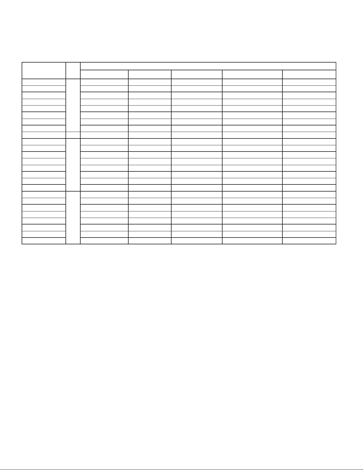
Page 31

GENERIC SERVICE PARTS LIST
Miscellaneous
NOITPIRCSED#TRAPNOITPIRCSED#TRAP
05/1/022-002,06/1/032-802ROTOMNAF0172801)V064(TSORFEDRIADRAOBLANIMRET710540
05/1/004-083,06/1/064ROTOMNAF11728017105401#draoblanimretV064rof,ROTALUSNI951171
06/1/575ROTOMNAF2172801GH
TNUOMROTOM1305401GNITTIFNIARD0135801
1000434216#/03WCL0203EDALBNAF9072801GNITTIFNIARD
)CITSALP(DRAUGNAF3072801GNITTIFNIARD-TEKSAG3011801
)ERIW(DRAUGNAF1905401NAPNIARD-TKRBNWODDLOH
C-924#YERGENOTNAP61-8/3NC#TUNNROCA1592801PMTKRBREGNAH1842801
HW/TUN
DRAUGERIW
RRETAEH9068401
LEETS
Defrost Heaters - Electric Defrost Models
SLEDOM
EM811EL611EV311
EM221EL911EV711
EM822EL522EV222
EM632EL232EV822
EM5
42EL042EV432
EM553EL843EV933
EM863EL653EV053
EM084EL174EV954
EM884A/NA/N
htiwesurof07-N#CNU-61-8/3KCOL-ZI
)PILCERIW(PM/PLLIOC-PILCRENIATE
SSELNIATS-PO"2X"2-AG61-0288#YSSAEGNIH
0905401
104061
V022-002
)DERIUQER4(
100-8203801/W046101-8203801/W925100-9203801/W984101-9203801/W404
100-8203801/W046101-8203801/W925100-9203801/W984101-9203801/W404
200-8203801/W2121201-8203801/W2001200-92038
200-8203801/W2121201-8203801/W2001200-9203801/W218201-9203801/W176
200-8203801/W2121201-8203801/W2001200-9203801/W218201-9203801/W176
300-8203801/W4871301-8203801/W4741300-9203801/W0311301-9203801/W839
300-8203801/W4871301-8203801/W4741300-920
400-8203801/W7802401-8203801/W5271400-9203801/W0131401-9203801/W08
400-8203801/W7802401-8203801/W5271400-9203801/W0131401-9203801/W0801
50Hz
&DEDRAOBLANIMRET0883801
-TUNKCOL2011801
RETAEH5003801
.gl"8/5x21#:SWERCS0011801
.gl"4/3x41#:SWERCS4773401
REBMUNTRAP
RETAEHECAFLIOC )DERIUQER1(RETAEHNAPNIARD
V004-083
)DERIUQER5(
V022-002V
01/W218201-9203801/W176
3801/W0311301-9203801/W839
01
1
004-083
- 31 -
Page 32

GENERIC SERVICE PARTS LIST
Defrost Heaters - Hot Gas Defrost with Electric Drain Pan
REBMUNTRAP
SLEDOM
V022-002V004-083
TM811GM811TL611GL611TV311GV311
TM221GM221TL911GL911TV711GV711
TM822GM822TL522GL522TV222GV222
TM632GM632TL232GL232TV822GV822
TM542GM542TL042GL042TV432GV432
TM553GM553TL843GL843TV933GV9
TM863GM863TL653GL653TV053GV053
TM084GM084TL
TM884GM884A/NA/NA/NA/N
174GL174TV954GV954
Drain Pan Assemblies
01/W218201-9203801/W176
33
100-9203801/W984101-9203801/W404
100-9203801/W984101-9
200-9203801/W218201-9203801/W176
200-92038
200-9203801/W218201-9203801/W176
300-9203801/W0311301-9203801/W839
300-9203801/W0311301-9203801/W839
400-9203801/W0131401-9203801/W0801
400-9203801/W0131401-9203801/W0801
50Hz
)DERIUQER1(RETAEHNAPNIARD
203801/W404
-TSORFEDCIRTCELE
REBMUN
SNAFFO
NAF1
SNAF2
SNAF3
SNAF4
dulcniseilbmessanapniarD
-TSORFEDRIA
SLEDOM"AM"
DA1-1113801DE1-1113801GH1-1113801
DA2-1113801DE2-1113801GH2-1113801
DA3-1113801DE3-1113801GH3-1
DA4-1113801DE4-1113801GH4-1113801
.spoolsagtohrosretaehedulcnitonodseilbmessanapniarD
SLEDOM"EV"&"EL","EM"
-NAPDEHTIWSAGTOH
SLEDOM"TV&TL,TM"
SLEDOM"GV&GL,GM"
113801
.elbacilppanehwstekcarbnwoddlohretaehdnaegnih,gnittifniarde
TSORFEDSAGTOH
NAPNIPOOLGH
SLEDOM"HV&HL,HM"
SLEDOM"RV&RL,RM"
- 32 -
Page 33

NOTES
- 33 -
Page 34

NOTES
- 34
Page 35

FINISHED GOODS WARRANTY
The terms and conditions as described below in the General Warranty Policy cover all products
manufactured by National Refrigeration.
GENERAL WARRANTY POLICY
Subject to the terms and conditions hereof, the Company warrants all Products, including Service
Parts, manufactured by the Company to be free of defects in material or workmanship, under normal
use and application for a period of one (1) year from the original date of installation, or eighteen (18)
months from the date of shipment from the Company, whichever occurs first. Any replacement
part(s) so supplied will be warranted for the balance of the product’s original warranty. The part(s) to
be replaced must be made available in exchange for the replacement part(s) and reasonable proof of
the original installation date of the product must be presented in order to establish the effective date
of the warranty , failing which, the ef fective date will be based upon the date of manufacture plus thirty
(30) days. Any labour, material, refrigerant, transportation, freight or other charges incurred in connection with the performance of this warranty will be the responsibility of the owner at the current
rates and prices then in effect. This warranty may be transferred to a subsequent owner of the
product.
THIS WARRANTY DOES NOT COVER
(a) Damages caused by accident, abuse, negligence, misuse, riot, fire, flood, or Acts of God (b) damages
caused by operating the product in a corrosive atmosphere (c) damages caused by any unauthorized
alteration or repair of the system affecting the product’s reliability or performance (d) damages caused
by improper matching or application of the product or the product’s components (e) damages caused
by failing to provide routine and proper maintenance or service to the product (f) expenses incurred for
the erecting, disconnecting, or dismantling the product (g) parts used in connection with normal
maintenance, such as filters or belts (h) products no longer at the site of the original installation (i)
products installed or operated other than in accordance with the printed instructions, with the local
installation or building codes and with good trade practices (j) products lost or stolen.
No one is authorized to change this WARRANTY or to create for or on behalf of the Company any
other obligation or liability in connection with the Product(s). There is no other representation, warranty
or condition in any respect, expressed or implied, made by or binding upon the Company other than the
above or as provided by provincial or state law and which cannot be limited or excluded by such law , nor
will we be liable in any way for incidental, consequential, or special damages however caused.
The provisions of this additional written warranty are in addition to and not a modification of or subtraction
from the statutory warranties and other rights and remedies provided by Federal, Provincial or State
laws.
PROJECT INFORMATION
metsyS
rebmuNledoM pU-tratSfoetaD
rebmuNlaireS rotcartnoCecivreS
tnaregirfeRenohP
ylppuSlacirtcelExaF
- 35 -
Page 36

“AS BUILT” SERVICE PARTS LIST
Service Parts ListService Parts List
Service Parts List
Service Parts ListService Parts List
LL
abelabel
L
abel
LL
abelabel
TT
o Be Ao Be A
T
o Be A
TT
o Be Ao Be A
HEREHERE
HERE
HEREHERE
ttachedttached
ttached
ttachedttached
NA TIONAL REFRIGERA TION &
AIR CONDITIONING CANADA CORP.
CANADA
159 ROY BLVD., BRANTFORD, ONTARIO, CANADA N3R 7K1
PHONE: 1-800-463-9517 (519)751-0444 FAX (519)753-1140
Due to National Refrigeration’s policy of continuous product improvement, we reserve the right to make changes without notice.
USA
985 WHEELER WA Y, LANGHORNE, PA. 19047 USA
PHONE:1-888-KEEPUS1 OR 1-888-533-7871
 Loading...