

Page 1
KLV Low Velocity
30/03/12
Evaporators
PRODUCT DATA &
INSTALLATION
Bulletin K30-KLV-PDI-22
1073480
Latest product updates and further information
at w w w . k e e pr it er e f r i g er at io n . c o m
KeepRite
Low Velocity Evaporators
NOMENCLATURE
KLV 150 ED - S2 B
Applications:
High Temperature
35 °F (2 °C) or Above Box Temperature and
Medium Temperature
28 °F to 34°F Box Temperature (-2 °C to 1 °C)
Defrost Types:
Air, Electric or Hot Gas Defrost
• Heavygaugetexturedaluminumcabinetconstruction
resistsscratches/corrosionandminimizesweightfor
shipment,installationandservice.
• High-efciencyPSCmotors.
• Speciallydesignedforquietoperation-idealfor
prep.rooms.
• Capacityupto37,000BTUHnominal.
• Dualrefrigerationcoilswithtwo-wayairdistribution
reducesairvelocitiestominimizeproductdehydration.
• Reducedoperatingchargewith3/8”ODtubing
• Spaciousendcompartmentallowsforeasy
componentinstallation.
• Attractiveanddurablehigh-densitypolypropylene
fanguards.
• Hingeddrainpanprovidesconvenientaccessfor
cleaning.
Terminalboardallowsforeasyelectricalconnections.
•
• RefrigerantsR22,R404A,R507,R134a,R407C.
• Options:-Factorymountedsolenoidvalve,TXVand
Thermostat.
-Finmaterialandspecialcoatings.
-EnergyEfcientECMotors
-Otheroptionsavailable-consultfactory.
Nominal Capacity @ 10
100=15000BTUH
Ratedat20oFEvap.Temp.
Type of Defrost
AD = Airdefrost
ED = ElectricDefrost
HE = 3PipeDefrost,ElectricHeatedDrainPan
RE = ReverseCycleDefrost,ElectricHeatedDrainPan
TE= ThermosaverDefrost,ElectricHeatedDrainPan
Electrical Designation
S1 = 115/1/60
S2 = 208-230/1/60
Unit Series
B=SecondGeneration
o
F TD150x
CONTENTS PAGE
Nomenclature.................................... Cover
Capacity Data ................................... 2
Electrical Data .................................. 3
Dimensional Data.............................. 4
Installation Clearances..................... 5
Wiring Diagrams............................... 6 - 10
TXV/ Distributor Nozzle Selection..... 11
Defrost Control Positions.................... 12
Installation Instructions...................... 13 - 15
Service Parts List............................... 15
Service Log....................................... 18
Warranty............................................ 19
Project Information............................ 19
“As Built” Service Parts List............... Back
Page 2
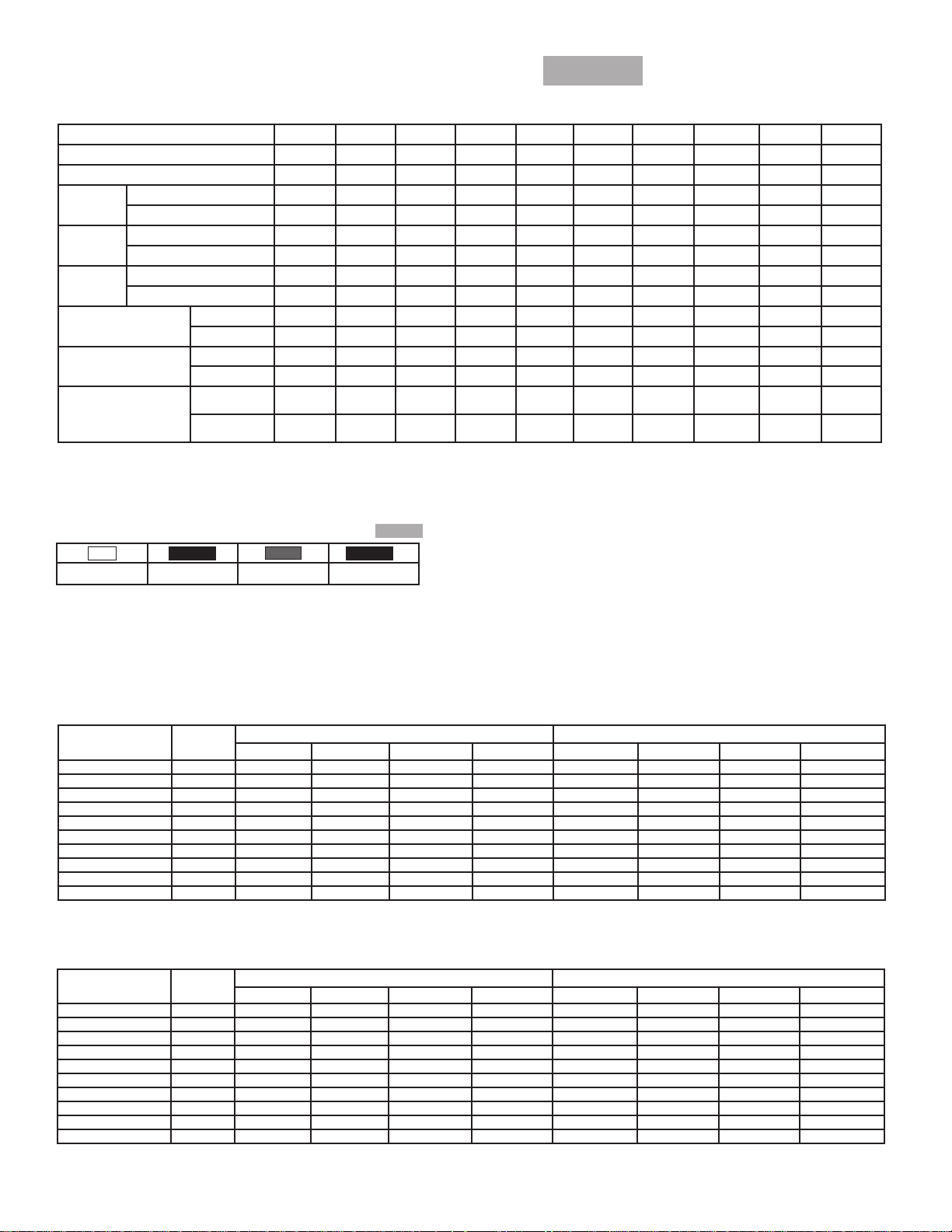
CAPACITY DATA -
K30-KLV-PDI-22
- 2 -
30/03/12
KLV
R404A
60Hz
ALL MODELS
High Temp. Model 060AD 090AD 120AD 150AD 180AD 220AD 270AD 300AD 340AD 370AD
Electric Defrost Model 060ED 090ED 120ED 150ED 180ED 220ED 270ED 300ED 340ED 370ED
Hot Gas Defrost Model
*Capacity
*Capacity
*Capacity
Air
Flow
Refrigerant
Charge **
Std. Unit Net
Weight
(w/o Refrigerant)
* Capacity rated with R404A @ +20°F(-6.6°C) S.S.T.
** R404A @ +20°F(-6.6°C) S.S.T. with coil 30 % full of liquid.
‡
Refer to Hot Gas Defrost nomenclature and insert appropriate code
NOTE: Defrost heaters can be eld converted to operate on 208-230/3/60
BTUH @ 1°F T.D. 600 900 1200 1500 1800 2200 2700 3000 3400 3700
(WATTS @ 0.55°C T.D.) (175.7) (263.5) (351.4) (439.2) (527.1) (644.2) (790.6) (878.4) (995.6) (1083.4)
BTUH @ 10°F T.D. 6000 9000 12000 15000 18000 22000 27000 30000 34000 37000
(WATTS @5.55°C T.D.) (1756.9) (2635.3) (3513.7) (4392.2) (5270.6) (6441.8) (7905.9) (8784.3) (9955.6) (10834)
BTUH @ 15°F T.D. 9000 13500 18000 22500 27000 33000 40500 45000 51000 55500
(WATTS @8.33°C T.D.) (2635.3) (3952.9) (5270.6) (6588.2) (7905.9) (9662.7) (11858.8) (13176.5) (14933.3) (16251)
CFM 850 1120 1500 2000 2530 2785 3400 4000 4370 4840
(L/S) (401) (529) (708) (944) (1194) (1314) (1605) (1888)
LB. 2.4 4.0 5.9 6.6 7.2 9.2 9.0 10.8 13.8 13.8
(KG) (1.2) (2.0) (3.0) (3.3) (3.6) (4.6) (4.5) (5.5) (7.0) (7.0)
LB. 90 105 139 158 220 235 257 270 280 290
(KG) (41) (48) (63) (72) (100) (107) (117) (123) (127) (132)
60
‡
90
‡
120
‡
150
‡
180
‡
220
‡
270
‡
300
‡
340
(2062) (2284)
‡
370
‡
R407C
R404A
Values Multiplied By:
*
Correction Factors for Other Refrigerants Use
R22
0.95 0.90 1.00 0.90
* When using R407C, the factor above is to be used when matching to condensing units with Dew Point ratings. This factor will ensure that proper
system balancing will occur to compensate for glide to t the application. If the system is sized correctly, one may expect a slight increase in system
capacity, along with slightly higher saturated suction temperatures.
R134a
R507
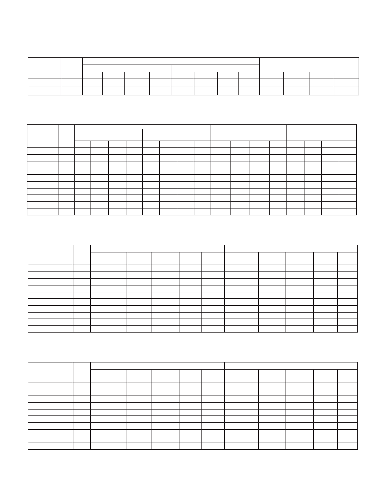
ELECTRICAL DATA
Air Defrost Models - 115/1/60
Model
KLV 060AD 1 1.1 1.4 90 15 0.8 1.0 55 15
KLV 090AD 1 1.1 1.4 130 15 1.6 2.0 95 15
KLV 120AD 2 2.2 2.5 180 15 1.6 1.8 110 15
KLV 150AD 2 2.2 2.5 260 15 3.2 3.6 190 15
KLV 180AD 3 3.3 3.6 270 15 2.4 2.6 165 15
KLV 220AD 3 3.3 3.6 390 15 4.8 5.2 285 15
KLV 270AD 3 3.3 3.6 390 15 4.8 5.2 285 15
KLV 300AD 4 4.4 4.7 520 15 6.4 6.8 380 15
KLV 340AD 4 4.4 4.7 520 15 6.4 6.8 380 15
KLV 370AD 5 5.5 5.8 650 15 8.0 8.4 475 15
FLA = Full Load Amps MCA = Minimum Circuit Ampacity MOP = Maximum Over Current Protection
* Electrical wiring is to be sized in accordance with minimum circuit ampacity
No. of
Fans
FLA MCA* Watts MOP FLA MCA* Watts MOP
Air Defrost Models - 208-230/1/60
Model
KLV 060AD 1 0.5 0.6 90 15 0.5 0.6 55 15
KLV 090AD 1 0.5 0.6 130 15 1.0 1.3 95 15
KLV 120AD 2 1.0 1.1 180 15 1.0 1.1 110 15
KLV 150AD 2 1.0 1.1 260 15 2.0 2.3 190 15
KLV 180AD 3 1.5 1.6 270 15 1.5 1.6 165 15
KLV 220AD 3 1.5 1.6 390 15 3.0 3.3 285 15
KLV 270AD 3 1.5 1.6 390 15 3.0 3.3 285 15
KLV 300AD 4 2.0 2.1 520 15 4.0 4.3 380 15
KLV 340AD 4 2.0 2.1 520 15 4.0 4.3 380 15
KLV 370AD 5 2.5 2.6 650 15 5.0 5.3 475 15
FLA = Full Load Amps MCA = Minimum Circuit Ampacity MOP = Maximum Over Current Protection
* Electrical wiring is to be sized in accordance with minimum circuit ampacity
No. of
Fans
FLA MCA* Watts MOP FLA MCA* Watts MOP
Standard PSC Motor Optional EC Motor
Standard PSC Motor Optional EC Motor
Page 3
ELECTRICAL DATA
K30-KLV-PDI-22
- 3 -
30/03/12
KLV
Electric Defrost Models - 115/1/60
Model
KLV 060ED 1 1.1 1.4 90 15 0.8 1.0 55 15 1880 16.4 20.4 25
KLV 090ED 1 1.1 1.4 130 15 1.6 2.0 95 15 1880 16.4 20.4 25
FLA = Full Load Amps MCA = Minimum Circuit Ampacity MOP = Maximum Over Current Protection
* Electrical wiring is to be sized in accordance with minimum circuit ampacity
No. of
Fans
Standard PSC Motor Optional EC Motor
FLA MCA* Watts MOP FLA MCA* Watts MOP Watts FLA MCA* MOP
Fan Motors
Electric Defrost Models - 208-230/1/60
Fan Motors - 208-230/1/60
Model
KLV 060ED 1 0.5 0.6 90 15 0.5 0.6 55 15 1880 8.2 10.2 15 1880 4.9 6.1 15
KLV 090ED 1 0.5 0.6 130 15 1.0 1.3 95 15 1880 8.2 10.2 15 1880 4.9 6.1 15
KLV 120ED 2 1.0 1.1 180 15 1.0 1.1 110 15 3180 13.8 17.3 20 3180 8.5 10.6 15
KLV 150ED 2 1.0 1.1 260 15 2.0 2.3 190 15 3180 13.8 17.3 20 3180 8.5 10.6 15
KLV 180ED 3 1.5 1.6 270 15 1.5 1.6 165 15 4540 19.7 24.7 25 4540 12.1 15.1 20
KLV 220ED 3 1.5 1.6 390 15 3.0 3.3 285 15 4540 19.7 24.7 25 4540 12.1 15.1
KLV 270ED 3 1.5 1.6 390 15 3.0 3.3 285 15 4540 19.7 24.7 25 4540 12.1 15.1 20
KLV 300ED 4 2.0 2.1 520 15 4.0 4.3 380 15 4540 19.7 24.7 25 4540 12.1 15.1 20
KLV 340ED 4 2.0 2.1 520 15 4.0 4.3 380 15 5580 24.3 30.3 35 5580 14.9 18.6 20
KLV 370ED 5 2.5 2.6 650 15 5.0 5.3 475 15 5580 24.3 30.3 35 5580 14.9 18.6 20
FLA = Full Load Amps MCA = Minimum Circuit Ampacity MOP = Maximum Over Current Protection
* Electrical wiring is to be sized in accordance with minimum circuit ampacity
No. of
Fans
Standard PSC Motor Optional EC Motor
FLA MCA* Watts MOP FLA MCA* Watts MOP Watts FLA MCA* MOP Watts FLA MCA* MOP
Defrost Heaters -
208/230/1/60
Defrost Heaters
converted to operate on 208-
60Hz
Defrost Heaters eld
230/3/60
20
Hot Gas Defrost Models - 115/1/60
Model
KLV 060 HE/RE 1 580 5.0 1.1 6.3 15 580 5.0 0.8 6.6 15
KLV 090 HE/RE 1 580 5.0 1.1 6.3 15 580 5.0 1.6 6.6 15
KLV 120 HE/RE 2 580 5.0 2.2 6.3 15 580 5.0 1.6 6.6 15
KLV 150 HE/RE 2 580 5.0 2.2 6.3 15 580 5.0 3.2 6.6 15
KLV 180 HE/RE 3 820 7.1 3.3 8.9 15 820 7.1 2.4 9.4 15
KLV 220 HE/RE 3 820 7.1 3.3 8.9 15 820 7.1 4.8 9.4 15
KLV 270 HE/RE 3 820 7.1 3.3 8.9 15 820 7.1 4.8 9.4 15
KLV 300 HE/RE 4 820 7.1 4.4 8.9 15 820 7.1 6.4 9.4 15
KLV 340 HE/RE 4 1020 8.9 4.4 11.1 15 1020 8.9 6.4 11.6 15
KLV 370 HE/RE 5 1020 8.9 5.5 11.1 15 1020 8.9 8 11.6 15
FLA = Full Load Amps MCA = Minimum Circuit Ampacity MOP = Maximum Over Current Protection
* Electrical wiring is to be sized in accordance with minimum circuit ampacity
No. of
Fans
Drain Pan
Heater Watts
Standard PSC Motor Optional EC Motor
Heater
Amps
Fan Motor
FLA
MCA* MOP
Drain Pan
Heater Watts
Heater
Amps
Fan Motor
FLA
MCA* MOP
Hot Gas Defrost Models - 208-230/1/60
Model
KLV 060 HE/RE 1 580 2.5 0.5 3.2 15 580 2.5 0.5 2.9 15
KLV 090 HE/RE 1 580 2.5 0.5 3.2 15 580 2.5 1.0 2.9 15
KLV 120 HE/RE 2 580 2.5 1.0 3.2 15 580 2.5 1.0 2.9 15
KLV 150 HE/RE 2 580 2.5 1.0 3.2 15 580 2.5 2.0 2.9 15
KLV 180 HE/RE 3 820 3.6 1.5 4.5 15 820 3.6 1.5 4.1 15
KLV 220 HE/RE 3 820 3.6 1.5 4.5 15 820 3.6 3.0 4.1 15
KLV 270 HE/RE 3 820 3.6 1.5 4.5 15 820 3.6 3.0 4.1 15
KLV 300 HE/RE 4 820 3.6 2.0 4.5 15 820 3.6 4.0 4.1 15
KLV 340 HE/RE 4 1020 4.4 2.0 5.5 15 1020 4.4 4.0 5.1 15
KLV 370 HE/RE 5 1020 4.4 2.5 5.5 15 1020 4.4 5.0 5.1 15
FLA = Full Load Amps MCA = Minimum Circuit Ampacity MOP = Maximum Over Current Protection
* Electrical wiring is to be sized in accordance with minimum circuit ampacity
No. of
Fans
Drain Pan
Heater Watts
Standard PSC Motor Optional EC Motor
Heater
Amps
Fan Motor
FLA
MCA* MOP
Drain Pan
Heater Watts
Heater
Amps
Fan Motor
FLA
MCA* MOP
Page 4
KLV
K30-KLV-PDI-22
- 4 -
30/03/12
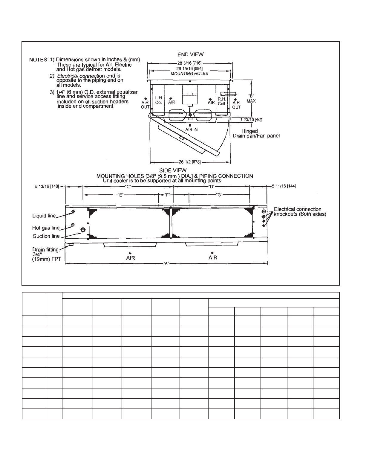
DIMENSIONAL DATA - Inches (mm)
60Hz
MODEL
* Reducer supplied to accomodate 1/2” or 7/8” TXV outlet connection.
No. of
Fans
060 1 5/8 (16) 1/2 (13) 1/2 (13)
090 1 7/8 (22) 1/2 (13) 1/2 (13)
120 2 7/8 (22) 1/2 (13) 1/2 (13)
150 2 1 1/8 (29) 1/2 (13) 1/2 (13)
180 3 1 1/8 (29) 1/2 (13) 1/2 (13)
220 3 1 1/8 (29) 1/2 (13) 1/2 (13)
270 3 1 1/8 (29) * 7/8 (22) 5/8 (16)
300 4 1 1/8 (29) * 7/8 (22) 5/8 (16)
340 4 1 3/8 (35) * 7/8 (22) 5/8 (16)
370 5 1 3/8 (35) * 7/8 (22) 5/8 (16)
Suction
Connection
(OD)
Distributor
Inlet
(OD)
Hot Gas
Side Conn.
(OD)
DIMENSIONAL DATA - INCHES (mm)
A B
66 7/8
(1699)
66 7/8
(1699)
66 7/8
(1699)
66 7/8
(1699)
92 7/8
(2359)
92 7/8
(2359)
92 7/8
(2359)
92 7/8
(2359)
112 7/8
(2867)
112 7/8
(2867)
8 11/16
(221)
9 9/16
(252)
12 7/16
(316)
14 15/16
(378)
14 15/16
(378)
14 15/16
(378)
17 7/16
(443)
17 7/16
(443)
17 7/16
(443)
17 7/16
(443)
Mounting Holes
C D E F G
27 1/2
(699)
27 1/2
(699)
27 1/2
(699)
27 1/2
(699)
40 1/2
(1029)
40 1/2
(1029)
40 1/2
(1029)
40 1/2
(1029)
- -
- -
27 1/2
(699)
27 1/2
(699)
27 1/2
(699)
27 1/2
(699)
40 1/2
(1029)
40 1/2
(1029)
40 1/2
(1029)
40 1/2
(1029)
- - -
- - -
- - -
- - -
- - -
- - -
- - -
- - -
40 1/2
(1029)
40 1/2
(1029)
20
(508)
20
(508)
40 1/2
(1029)
40 1/2
(1029)
Page 5
KLV
K30-KLV-PDI-22
- 5 -
30/03/12
RECOMMENDED
60Hz
INSTALLATION CLEARANCES
DIMENSION A B C D
Minimum
Maximum
ft. 2 2 6 3
(cm.) (61) (61) (183) (92)
ft. - 7 40 20
(cm.) - (210) (1200) (600)
Page 6
KLV
K30-KLV-PDI-22
- 6 -
30/03/12
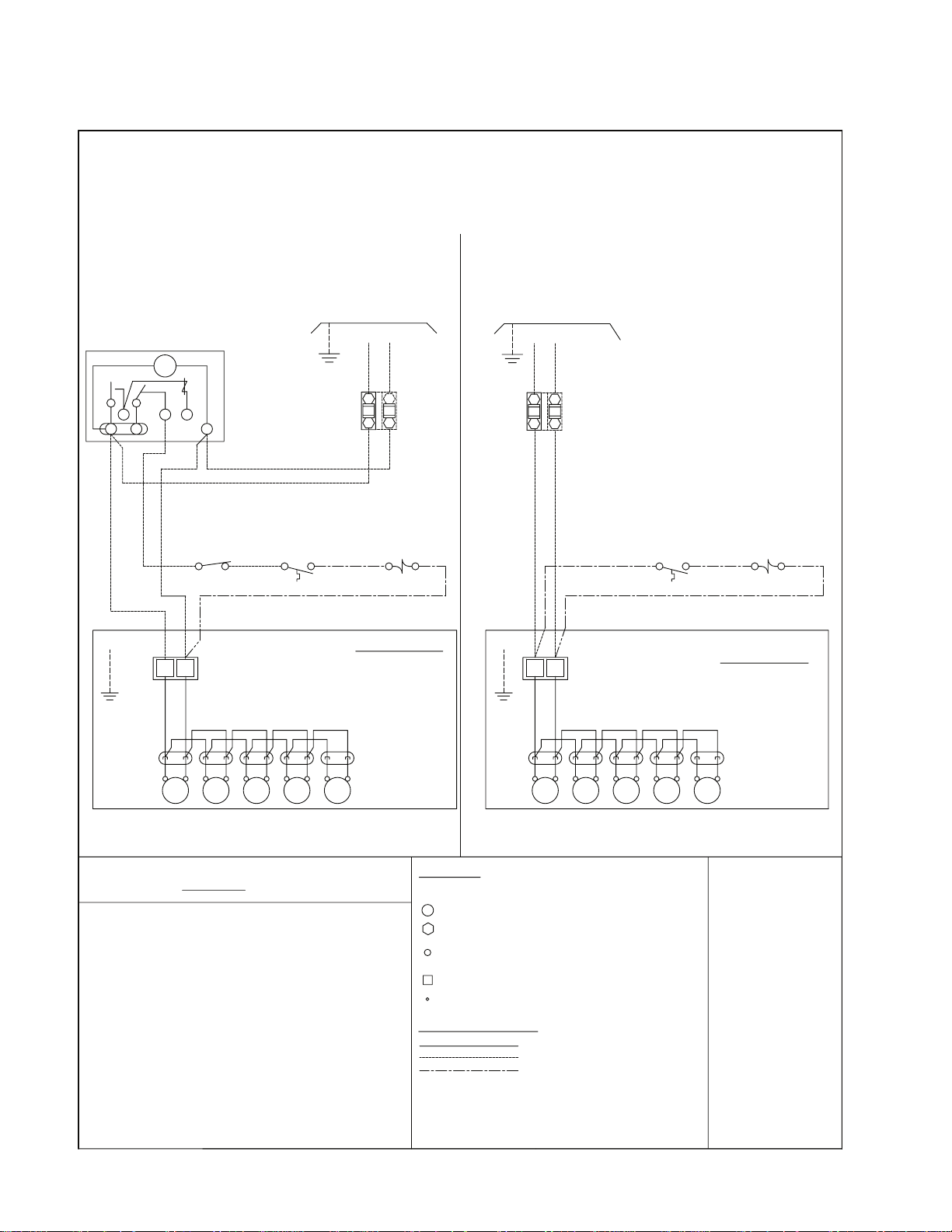
WIRING DIAGRAM
60Hz
Air Defrost - All Voltages
AIR DEFROST
TYPICAL WIRING:
WITH DEFROST TIME CLOCK
DEFROST CLOCK
PARAGON # 8145
OR EQUIVALENT
TM
3
1 2
4 X
PUMP DOWN
N
SWITCH
(IF USED)
NAMEPLATE FOR ELECTRICAL
SPACE
THERMOSTAT
NOTE #4
FOR MULTIPLE EVAPORATORS AND OTHER
ALTERNATIVE WIRING, SEE INSTALLATION MANUAL
REFER TO EVAPORATOR
REQUIREMENTS
L2(N)
L1
GND
FUSE OR
CIRCUIT
BREAKER
NOTE #3
SOLENOID VALVE
OMIT
FUSE
IF (N)
LIQUID LINE
NOTE #4
WITHOUT DEFROST TIME CLOCK
REFER TO EVAPORATOR
NAMEPLATE FOR ELECTRICAL
REQUIREMENTS
L2(N)
L1
GND
FUSE OR
CIRCUIT
BREAKER
NOTE #3
OMIT
FUSE
IF (N)
SPACE
THERMOSTAT
NOTE #4
LIQUID LINE
SOLENOID VALVE
NOTE #4
4
F
TERMINAL BOARD
GND.
RIBBED
FAN
MTR
PLAIN
FAN
MTR
FAN
MTR
FAN
MTR
NOTES
1). USE COPPER CONDUCTORS ONLY
2). USE 75°C WIRE (OR HIGHER)
3). OVERCURRENT PROTECTION FOR
EVAPORATOR FAN MOTORS AND DEFROST
HEATERS MUST NOT EXCEED MAXIMUM
VALUE SHOWN ON EVAPORATOR NAMEPLATE.
4). MAY BE FACTORY INSTALLED-MOUNTED
AND WIRED ON EVAPORATOR
(PRE-ASSEMBLED MODELS)
EVAPORATOR
FAN MOTOR
POWER PLUGS
REFER TO EVAPORATOR
FAN
DATA PLATE FOR
MTR
MOTOR QUANTITY
4
F
TERMINAL BOARD
GND.
TERMINALS
DH -DRAIN PAN HEATER
-COMP0NENT TERMINAL - MARKED
-COMPONENT TERMINAL - UNMARKED
( IDENTIFIABLE BY LOCATION )
-COMPONENT TERMINAL - UNMARKED
( UNIDENTIFIABLE )
-TERMINAL BLOCK TERMINAL
-WIRE SPLICE
CONDUCTORS/WIRING
ALL FIELD WIRING MUST BE DONE IN
COMPLIANCE WITH ALL APPLICABLE LOCAL
AND NATIONAL CODES.
PLAIN
RIBBED
FAN
FAN
MTR
FACTORY WIRING
WIRING BY OTHERS
OPTIONAL FACTORY OR
BY OTHERS
FAN FAN
MTR
MTR
FAN
MTR
EVAPORATOR
FAN MOTOR
POWER PLUGS
REFER TO EVAPORATOR
DATA PLATE FOR
MTR
MOTOR QUANTITY
REV A
11/05/01
1073979
Page 7

KLV
K30-KLV-PDI-22
- 7 -
30/03/12
DEFROST CLOCK
PARAGON # 8145
OR EQUIVALENT
3
1 2
TERMINAL
BOARD
GND.
WIRING DIAGRAM
Electric Defrost - Single Evaporator
ELECTRIC DEFROST
EVAPORATOR WITH DEFROST HEATER CONTACTOR
TYPICAL WIRING:
TM
4NX
4
RIBBED
FAN
MTR
F
PLAIN
PUMP DOWN
(IF USED)
X
RD
DEFROST TERMINATION
(CLOSES AT 55°F)
(OPENS AT 35°F)
FAN
MTR
FUSE OR
CIRCUIT
BREAKER
NOTE #3
COMPR CONTACTOR
AUXILLARY
(DEFR. HTR. LOCKOUT)
SWITCH
OR JUMPER
FAN
MTR
SPACE
THERMOSTAT
NOTE #4
ORANGE
3
JUMPER
RD
FAN
MTR
FOR MULTIPLE EVAPORATORS AND OTHER
ALTERNATIVE WIRING, SEE INSTALLATION MANUAL
REFER TO EVAPORATOR
NAMEPLATE FOR ELECTRICAL
L3
L3
T3
N
RD
NOTE #6
DEFROST
HEATER
CONTACTOR
TO H3
GND
FUSE OR
CIRCUIT
BREAKER
NOTE #3
LIQUID LINE
SOLENOID VALVE
NOTE #4
"Y"
H1
BK
R.H. COIL
BOTTOM
BK
BK
L.H. COIL
BOTTOM
BK
R.H.COIL
TOP
BK
FAN MOTOR
POWER PLUGS
REFER TO EVAPORATOR
DATA PLATE FOR
FAN
MOTOR QUANTITY
MTR
C
H2
L.H.
DRAIN PAN
YL
DRAIN PAN
BK
YL
L.H.COIL
TOP
BK
EVAPORATOR
L1
ORANGE
JUMPER
YL
R.H.
L2
L2
L1
T2
T1
H3
YL
BK
FOR THREE PHASE
NOTE #6
H1
DRAIN PAN
YL
BK
BK
H2
YL
L.H.
DRAIN PAN
YL
L.H.COIL
TOP
BK
NOTE #5
R.H.
BK
R.H. COIL
BOTTOM
BK
L.H. COIL
BOTTOM
BK
R.H.COIL
TOP
HEATER LOADS MUST NOT
EXEED CONTACT RATING.
FOR THREE PHASE HEATER
OPERATION (FIELD CONVERSION)
A. REMOVE ORANGE JUMPER
BETWEEN TERMINALS
H3
AND
H2
B. RECONNECT L.H. BOTTOM
HEATER WIRE (SHOWN AS "Y")
H1
FROM
TO
60Hz
"Y"
H3H2
BK
YL
BK
NOTES
1). USE COPPER CONDUCTORS ONLY
2). USE 75°C WIRE (OR HIGHER)
3). OVERCURRENT PROTECTION FOR
EVAPORATOR FAN MOTORS AND DEFROST
HEATERS MUST NOT EXCEED MAXIMUM
VALUE SHOWN ON EVAPORATOR NAMEPLATE.
4). MAY BE FACTORY INSTALLED-MOUNTED
AND WIRED ON EVAPORATOR
(PRE-ASSEMBLED MODELS)
ON MULTIPLE PRE-ASSEMBLED EVAPORATORS
WIRE SECOND EVAPORATOR SOLENOID IN
PARALLEL WITH FIRST ONE. ONLY USE ONE
THERMOSTAT.
5). THESE HEATERS NOT USED ON _LV060ED
AND _LV090ED MODELS
TERMINALS
-COMP0NENT TERMINAL - MARKED
-COMPONENT TERMINAL - UNMARKED
( IDENTIFIABLE BY LOCATION )
-COMPONENT TERMINAL - UNMARKED
( UNIDENTIFIABLE )
-TERMINAL BLOCK TERMINAL
-WIRE SPLICE
CONDUCTORS/WIRING
ALL FIELD WIRING MUST BE DONE IN
COMPLIANCE WITH ALL APPLICABLE LOCAL
AND NATIONAL CODES.
FACTORY WIRING
WIRING BY OTHERS
OPTIONAL FACTORY
OR BY OTHERS
REV B
11/05/01
1073978
Page 8

KLV
K30-KLV-PDI-22
- 8 -
30/03/12
WIRING DIAGRAM
Electric Defrost - Multiple Evaporators
FOR ALL MODELS USING DEFROST HEATER CONTACTOR
60Hz
Page 9

KLV
K30-KLV-PDI-22
- 9 -
30/03/12
WIRING DIAGRAM
Electric Defrost - (For optional use on models 060ED
and 090ED operating on 208-230/1/60)
ELECTRIC DEFROST
EVAPORATOR WITHOUT DEFROST HEATER CONTACTOR
USING MAX 15A HEATER OVERCURRENT PROTECTION
TYPICAL WIRING:
FOR MULTIPLE EVAPORATORS AND OTHER
ALTERNATIVE WIRING, SEE INSTALLATION MANUAL
60Hz
DEFROST CLOCK
PARAGON # 8145
OR EQUIVALENT
TM
4
231
4
F
GND.
PLAIN
RIBBED
X
N
PUMP DOWN
SWITCH
(IF USED)
X
RD
DEFROST TERMINATION
(CLOSES AT 55°F)
(OPENS AT 35°F)
RD
NAMEPLATE FOR ELECTRICAL
SPACE
THERMOSTAT
NOTE #4
ORANGE JUMPER
ORANGE
JUMPER
H1
3
REFER TO EVAPORATOR
REQUIREMENTS
L2(N)
L1
GND
FUSE OR
CIRCUIT
BREAKER
NOTE #3
LIQUID LINE
SOLENOID VALVE
NOTE #4
H2
R.H.
COIL
BK
BK
BK
L.H.
COIL
YL
BK
OR
JMPR
DRAIN
YL
L.H.
PAN
R.H.
DRAIN
PAN
MAX 15A
OR
H3
N
JMPR
YL
YL
NOTES
1). USE COPPER CONDUCTORS ONLY
2). USE 75°C WIRE (OR HIGHER)
3). OVERCURRENT PROTECTION FOR
EVAPORATOR FAN MOTORS AND DEFROST
HEATERS MUST NOT EXCEED MAXIMUM
VALUE SHOWN ON EVAPORATOR NAMEPLATE.
4). MAY BE FACTORY INSTALLED-MOUNTED
AND WIRED ON EVAPORATOR
(PRE-ASSEMBLED MODELS)
ON MULTIPLE PRE-ASSEMBLED EVAPORATORS
WIRE SECOND EVAPORATOR SOLENOID IN
PARALLEL WITH FIRST ONE. ONLY USE ONE
THERMOSTAT.
FAN
MTR
MTR MTR
FANFAN
MTR
RD
FAN MOTOR
POWER PLUGS
REFER TO EVAPORATOR
DATA PLATE FOR
FAN
FAN
MTR
MOTOR QUANTITY
EVAPORATOR
TERMINALS
-COMP0NENT TERMINAL - MARKED
-COMPONENT TERMINAL - UNMARKED
( IDENTIFIABLE BY LOCATION )
-COMPONENT TERMINAL - UNMARKED
( UNIDENTIFIABLE )
-TERMINAL BLOCK TERMINAL
-WIRE SPLICE
CONDUCTORS/WIRING
ALL FIELD WIRING MUST BE DONE IN
COMPLIANCE WITH ALL APPLICABLE LOCAL
AND NATIONAL CODES.
FACTORY WIRING
WIRING BY OTHERS
OPTIONAL FACTORY
OR BY OTHERS
1074180
REV-A
Page 10

KLV
K30-KLV-PDI-22
- 10 -
30/03/12
WIRING DIAGRAM
60Hz
Hot Gas Defrost - All Voltages
REVERSE CYCLE AND 3-PIPE HOT GAS DEFROST
Page 11

KLV
K30-KLV-PDI-22
- 11 -
30/03/12
THERMOSTATIC EXPANSION VALVE
60Hz
SELECTION - SPORLAN
MODEL NO. TD °F TD (°C)
060
090
120
180
270
340
370
SELECTIONS BASED ON 100°F(37.7°C) LIQUID
10 (5.6)
15 (8.3)
10 (5.6)
15 (8.3)
10 (5.6)
15 (8.3)
10 (5.6)
15 (8.3)
10 (5.6)
15 (8.3)
10 (5.6)
15 (8.3)
10 (5.6)
15 (8.3)
10 (5.6)
15 (8.3)
10 (5.6)
15 (8.3)
10 (5.6)
15 (8.3)
R22
EGVE-3/4-C EGSE-1/2-C
EGVE-1-C EGSE-1-C EGPE-1-C
EGVE-1 1/2-C EGSE-1 1/2-C EGPE-1 1/2-C150
EGVE-2-C
EGVE-3-C
SVE-4-C SSE-4-C SPE-4-C
R404A R507
EGPE-1/2-C
EGPE-1-C
EGSE-2-C EGPE-2-C220
SSE-3-C SPE-3-C300
DISTRIBUTOR NOZZLE SELECTION
STANDARD NOZZLES FACTORY INSTALLED FOR ALL MODELS
T.D. 8 °F TO 12 °F (4.4 °C to 6.6 °C)
EVAP. TEMP. RANGE 18 °F TO 40 °F (-7.7 °C TO 4.4 °C)
REFRIGERANT R22, R-404A, R507, R407C
060 L-3/4
090 L- 1
120, 150 L-1 1/2
180 L- 2
220 L-2 1/2
270 G- 2 1/2
300 G- 3
340, 370 G-4
SELECTIONS BASED ON 100 °F(37.7 °C) LIQUID
Page 12

KLV
K30-KLV-PDI-22
- 12 -
30/03/12
DEFROST CONTROL POSITIONS
60Hz
FAN/HEATER CONTROL
AND DEFROST TERMINATION CONTROL POSITION
HOT GAS DEFROST (REVERSE CYCLE)
HOT GAS DEFROST (3-PIPE OR BYPASS)
Page 13

KLV
K30-KLV-PDI-22
- 13 -
30/03/12
INSTALLATION INSTRUCTIONS
60Hz
INSTALLATION
The installation and start-up of LV Evaporators should only be
performed by qualied refrigeration mechanics.
This equipment should be installed in accordance with all applicable codes, ordinances and local by-laws.
INSPECTION
Inspect all equipment before unpacking for visible signs of
damage or loss. Check shipping list against material received to
ensure shipment is complete.
IMPORTANT: Remember, you, the consignee, must make any
claim necessary against the transportation company. Shipping
damage or missing parts, when discovered at the outset, will
prevent later unnecessary and costly delays.
If damage or loss during transport is evident, make claim to
carrier, as this will be their responsibility, not the
manufacturer’s.
Should carton be damaged, but damage to equipment is not
obvious, a claim should be led for “concealed damage” with the
carrier.
IMPORTANT: The electrical characteristics of the unit should
be checked at this time to make sure they correspond to those
ordered and to electrical power available at the job site.
LOCATION
The unit location in the room should be selected to ensure
uniform air distribution throughout the entire space to be
refrigerated. Be sure that the unit does not draw air in, or
blow directly out, through an opened door and that the
product does not obstruct the free circulation of air. Allow a
minimum of 24” clearance at each end. LV Evaporators draw
air through the fans and discharge air through both coils.
Consideration should be given to the coil location in order
to minimize the piping run length to the condensing unit and
oor drain.
EXPANSION VALVE (TXV) SELECTION
All units require the use of an externally equalized
expansion valve. (A 1/4” (6 mm) O.D. equalizer line has been
provided on the coil) TX valves should not be selected strictly
by their nominal ton rating. (This rating is based at a specic
pressure differential and entering liquid
temperature). Since applications will differ it is suggested the
following selection procedure be followed.
1. Determine actual unit cooler BTUH or KW (thermal).
The nominal rating is based at 10 °F T.D. (5 .5°C)
(Room Temp. minus Evap. Temp.). Note that a higher /
lower operating T.D.will increase / decrease this capacity
rating by their direct ratio.
Save all shipping papers, tags and instruction sheets for
reference by installer and owner.
APPLICATION
LV Unit Coolers are designed for use with R22, R404A, R134a,
R407C or R507 refrigerants. At room temperatures above 34°F
(1.1 C) (and evaporating temps no lower than 24 °F (-4.4°C))
positive coil defrosting (Electric or Hot Gas) is not required. (The
air owing through the coil will accomplish the defrost). At room
temperatures of 34°F (1.1°C) and below, positive defrosting is
required (either Electric (ED) or Hot Gas (HE, RE, TE) in model
nomenclature). These models require the use of (1) Time Clock
or equivalent (to initiate and terminate the defrost cycle), and (2)
Defrost Termination Control (to prevent unnecessary prolonged
heating and steaming of the coil once all the ice and frost has
melted), (3) Hot Gas models also utilize a Fan/Heater drain pan
control.
The coil must not be exposed to any abnormal atmospheric or
acidic environments. This may result in corrosion to the cabinet
and possible coil failure (leaks). (Consult manufacturer for
optional baked on phenolic protective coatings).
2. Determine the pressure drop across the valve by
subtracting the suction (evaporating) pressure from the
high side liquid pressure. Note: Also subtract the
distributor pressure loss (use approx. 25 psig (1.1 bar)
for R134a and 35 psig (2.4 bar) for R22, R404A, R507).
3. Estimate entering liquid temperature. Temperatures
lower than 100 °F (37.7 °C) increase valve capacity
ratings. Refer to valve manufacturer’s specs for details.
4. Select valve from the valve manufacturer selection charts
for the appropriate refrigerant, evaporating temp and
pressure drop.
5. After following the manufacturer’s installation instructions
and after the room has reached the desired temperature
the valve superheat should be checked. This will conrm
that the evaporator is operating properly and performing
to maximum efciency. The superheat should be around
5 (2.7°C) to 8 °F (4.4°C) for a 10 to 12 °F (5.5 to 6.6°C)
T.D. Too high or low a super heat will result in
unsatisfactory system performance and possible
compressor problems.
NOZZLE INSTALLATION
All LV Evaporators have nozzles installed at factory. For nozzle selection refer to selection table. In case it is
required to install the nozzle at some point in the future, the
nozzle retainer clip (in distributor) must be removed before
inserting nozzle. Re-install clip ensuring nozzle is properly in
place.
Page 14

KLV
K30-KLV-PDI-22
- 14 -
30/03/12
INSTALLATION INSTRUCTIONS (cont’d)
60Hz
MOUNTING
Refer to dimensional drawing for recommended mounting arrangements. Formed mounting channels are provided for ush
mounting to the ceiling. Ensure adequate clearance (at least
24” (600 mm)) is provided at each end (to enable access to the
electrical and refrig. compartments).
Ensure that the ceiling is level since the drain pan has
been sloped for drainage during the defrost cycle.
DRAIN LINE
The drain line should be run from the drain connection, sloping
at least 1/4” (6 mm) per foot. A trap in a warm area outside the
room will allow proper draining through the tubing. Connection
should be made to proper drainage facilities that comply with
local regulations.
To prevent freeze-up when the temperature of the refrigerated
space is 35
along its run inside the cold room. The heated drain line should
be insulated. It is recommended that the heater be energized
at all times. A heat input of 20 watts per foot in a 28°F (-2.2°C)
room, is satisfactory. Drain line heaters are not required for
constant room temperature above 35°F (1.6°C).
Ensure that the drain line has sufcient slope for proper
drainage (prevention of ice build up/blockage in pan).
o
F (1.7 °C) or lower, the drain line should be heated
PIPING
Refrigerant line sizes are important and may not be the same
size as the coil connections. Consult “Recommended refrigerant line sizes” charts in any standard reference book for proper
line sizing.
Refrigerant piping and control system should be designed to
prevent possible liquid slugging (from oil or refrigerant) of the
compressors on start-up after the defrost cycle. On Hot Gas
Defrost Systems the suction accumulator should be at least 2.5
times the coils operating charge.
See Dimensional data for line locations. For Reverse Cycle
and Hot Gas models and 3-Pipe - see g. 2 & 3 respectively on
page 12 for typical unit piping. These models include a check
valve (unmounted) packaged along with the nozzle in the
refrig. connection compartment end panel.
WIRING
Wire system in accordance with governing standards and local
codes. See data and wiring diagrams on pages 6 to 10 for wiring arrangement. Electrical wiring is to be sized in accordance
with minimum circuit ampacity rating (MCA).
For ease of identifying the proper wiring terminal, unit wiring is
color coded and terminal block connections are identied.
SYSTEM CHECK
Before Start-Up:
1. All wiring should be in accordance with local codes.
2. Refrigerant lines should be properly sized.
3. Off cycle defrost and electric defrost systems preferably
must include a liqud line solenoid valve and suction
accumulator.
4. Thorough evacuation and, dehydration has been
performed.
5. The suction, discharge, and receiver service valves must
be open.
6. The system preferably must include a liquid line drier
moisture indicator and suction lter.
7. Pour enough water into the drain pan to allow a good check
on drainage and seal the trap.
After Start-Up:
1. Check the oil level to be sure the oil charge is correct.
2. On initial start up the fans do not start until coil temperature
is pulled down to approximately 35 °F (1.7 °C) on the hot
gas coil. Also, it is normal for the fans to cycle a few times
until the room temperature is pulled down.
3. Fan/Heater control and defrost termination control is
factory installed for reverse cycle defrost operation. Refer
to Fig. 1 on page 12.
4. If coil is to be used for 3-pipe (bypass) Hot Gas Defrost,
Fan/Heater must be moved from suction line to hot gas
inlet line and the defrost termination control moved to the
suction line. Refer to Fig. 1 on page 12.
5. In general, evaporators running with a TD of 10 °F should
have a superheat reading of 5° to 8 °F (2.7 °C to 4.4 °C).
For evaporators with a higher TD, the superheat should be
8° to 12°F (4.4 °C to 6.6 °C).
6. Heavy moisture loads are usually encountered when
starting the system for the rst time. This will cause a rapid
build-up of frost on the unit cooler. During the initial pull
down, we suggest that the frost build-up be watched and
defrosted manually as required. This may be done by
rotating the inner dial on the timer until the pin in the outer
dial is directly opposite the timer pointer. (Paragon 8145-
20 Timer by others).
7. Observe that the system goes through at least one
complete DEFROST CYCLE.
MAINTENANCE
The unit should be periodically inspected for any dirt or
build-up on the n surface and cleaned if necessary with a soft
whisk or brush. Also ensure coils inner and outer drain pans
do not have any ice build-up from improper defrost operation.
When replacing heater elements rst remove heater retainer
brackets and heater clips.
Page 15

SERVICE PARTS LIST
K30-KLV-PDI-22
- 15 -
30/03/12
KLV
Motors Models Part Number
100V-115V PSC, 1/15HP All 1073403
200V-230V PSC,1/15HP All 1073405
100V-115V ECM 060, 120, 180 1086913
100V-115V ECM 090, 150, 220, 270, 300, 340, 370 1086912
200V-230V ECM 060, 120, 180 1086915
200V-230V ECM 090, 150, 220, 270, 300, 340, 370 1086914
Heaters
Coil Face Heater, 115V, 650W 060, 090, 120, 150 1070854-003
Coil Face Heater, 115V, 930W 180, 220, 270, 300 1070854-002
Coil Face Heater, 115V, 1140W 340, 370 1070854-001
Drain Pan Heater, 115V, 290W 060, 090, 120, 150 1070854-006
Drain Pan Heater, 115V, 410W 180, 220, 270, 300 1070854-005
Drain Pan Heater, 115V, 510W 340, 370 1070854-004
Fan Blades
14” 35° 5 Blades 090, 270, 340 1073414
14” 32° 5 Blades 150, 220, 300, 370 1073415
14” 22° 5 Blades 060, 120, 180 1073416
Fan/Heater Control Hot Gas Defrost Models (RE & HE) 1073640
Defrost Termination All 1071280
Fan Guard All 1073456
60Hz
Page 16

KLV
K30-KLV-PDI-22
- 16 -
30/03/12
NOTES
60Hz
Page 17

KLV
K30-KLV-PDI-22
- 17 -
30/03/12
NOTES
60Hz
Page 18

KLV
K30-KLV-PDI-22
- 18 -
30/03/12
DATE COMMENTS
SERVICE LOG
60Hz
Page 19

FINISHED GOODS WARRANTY
K30-KLV-PDI-22
- 19 -
30/03/12
The terms and conditions as described below in the General Warranty Policy cover all products
manufactured by National Refrigeration.
GENERAL WARRANTY POLICY
Subject to the terms and conditions hereof, the Company warrants all Products, including Service
Parts, manufactured by the Company to be free of defects in material or workmanship, under normal use and application for a period of one (1) year from the original date of installation, or eighteen
(18) months from the date of shipment from the Company, whichever occurs rst. Any replacement
part(s) so supplied will be warranted for the balance of the product’s original warranty. The part(s) to
be replaced must be made available in exchange for the replacement part(s) and reasonable proof
of the original installation date of the product must be presented in order to establish the effective
date of the warranty, failing which, the effective date will be based upon the date of manufacture plus
thirty (30) days. Any labour, material, refrigerant, transportation, freight or other charges incurred in
connection with the performance of this warranty will be the responsibility of the owner at the current rates and prices then in effect. This warranty may be transferred to a subsequent owner of the
product.
THIS WARRANTY DOES NOT COVER
(a) Damages caused by accident, abuse, negligence, misuse, riot, re, ood, or Acts of God (b) damages
caused by operating the product in a corrosive atmosphere (c) damages caused by any unauthorized
alteration or repair of the system affecting the product’s reliability or performance (d) damages caused
by improper matching or application of the product or the product’s components (e) damages caused by
failing to provide routine and proper maintenance or service to the product (f) expenses incurred for the
erecting, disconnecting, or dismantling the product (g) parts used in connection with normal maintenance,
such as lters or belts (h) products no longer at the site of the original installation (i) products installed
or operated other than in accordance with the printed instructions, with the local installation or building
codes and with good trade practices (j) products lost or stolen.
No one is authorized to change this WARRANTY or to create for or on behalf of the Company any
other obligation or liability in connection with the Product(s). There is no other representation, warranty
or condition in any respect, expressed or implied, made by or binding upon the Company other than
the above or as provided by provincial or state law and which cannot be limited or excluded by such
law, nor will we be liable in any way for incidental, consequential, or special damages however caused.
The provisions of this additional written warranty are in addition to and not a modication of or subtraction
from the statutory warranties and other rights and remedies provided by Federal, Provincial or State laws.
PROJECT INFORMATION
Sy stem
Mo del N umber Date of S tart- Up
Se rial Numbe r Servi ce Co ntrac tor
Re frige rant Pho ne
El ectri cal S upply Fa x
Page 20

“AS BUILT” SERVICE PARTS LIST
30/03/12
Service Parts List
Label
To Be Attached
HERE
NATIONAL REFRIGERATION &
AIR CONDITIONING CANADA CORP.
CANADA
159 ROY BLVD., BRANTFORD, ONTARIO, CANADA N3R 7K1
PHONE: 1-800-463-9517 (519)751-0444 FAX (519)753-1140
Due to National Refrigeration’s policy of continuous product improvement, we reserve the right to make changes without notice.
USA
985 WHEELER WAY, LANGHORNE, PA. 19047 USA
PHONE: 1-888-KEEPUS1 OR 1-888-533-7871
 Loading...