

Page 1
PRODUCT DATA &
03/22/11
INSTALLATION
Bulletin K30-KHPHG-PDI-2
1081591
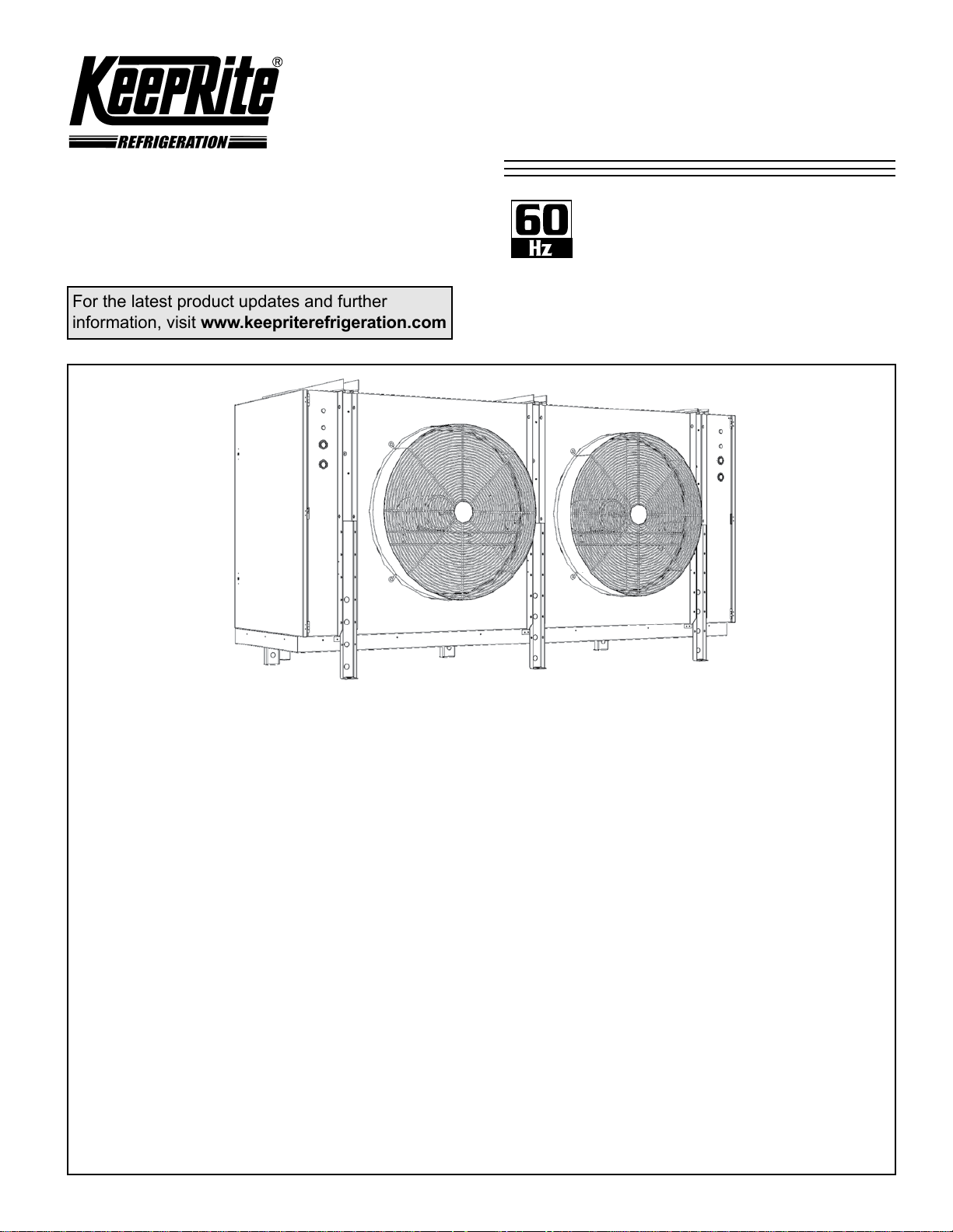
High Prole
Evaporator
Low & Medium Temp.
Hot Gas Defrost
For the latest product updates and further
information, visit www.keepriterefrigeration.com
Electrical Power:
208-230/3/60, 460/3/60, 575/3/60
CONTENTS
Nomenclature................................................................................................................. 2
Features & Options........................................................................................................ 2
Standard Velocity Units.................................................................................................. 3-6
Capacity Data........................................................................................................... 3
Electrical Data.......................................................................................................... 4-6
Wiring Diagram............................................................................................................... 7
Piping Schematic............................................................................................................ 8
Dimensional Data........................................................................................................... 9,10
Specications................................................................................................................. 11,12
Installation Instructions................................................................................................... 13,14
High Velocity Units......................................................................................................... 15 - 20
Capacity Data.......................................................................................................... 15 - 17
Electrical Data......................................................................................................... 18 - 20
Service Parts List........................................................................................................... 21
Warranty......................................................................................................................... 23
Project Information......................................................................................................... 23
“As Built” Service Parts List............................................................................................ BACK
Project Information......................................................................................................... BACK
Page
Page 2
NOMENCLATURE
K30-KHPHG-PDI-2
- 2 -
03/22/11
K HP 216 L E - T5 A - S B
K = KeepRite
High Prole Evaporator
Nominal Capacity x 1000
(standard motor/fan blade) @ 10°F TD
Application Range
H = Hi / Medium Temp 7 FPI (0°F to 35°F Evap Temp)
M = Medium Temp 6 FPI (0°F to 35°F Evap Temp)
P = Medium Temp 4 FPI (0°F to 35°F Evap Temp)
L = Low Temp 6 FPI (-5°F to -40°F Evap Temp)
V = Low Temp 4 FPI (-5°F to -40°F Evap Temp)
Defrost
A = Air
E = Electric
T = 3 Pipe Hot Gas w/ Heater
G = Reverse Cycle Hot Gas w/ Heater
H = 3 Pipe Hot gas w/ Loop
R = Reverse Cycle Hot Gas w/ Loop
STANDARD FEATURES
• Heavy gauge textured aluminum cabinet
with galvanized steel hangers, support channels
and end plates
• Hinged access panels with removable hinge
pins and captive fasteners.
• Rugged heavy-gauge galvanized steel rail
motor mount / support
• Stackable design
Throw Boosters:
N = None
B = Booster
Motor Option:
S = Standard
T = TEFC
V = High Velocity
† Not available on above
+15°F Evap. Temp. models
Generation
st
A = 1
Voltage:
T3 = 208-230/3/60
T4 = 460/3/60
T5 = 575/3/60
T7 = 200-220/3/50
T9 = 380-400/3/50
†
• Drain pan heaters
• Fixed fan delay thermostat (all low
temperature models)
• Adjustable fan delay thermostat (all medium
temperature models)
• Schrader tting and external equalizer line
• Adjustable defrost termination thermostat
• Heater safety thermostat (on models with heaters)
• Factory mounted TX valve, solenoid valve
and thermostat
• Throw boosters
• Insulated drain pan
• 3 HP 1750 RPM motor with cast aluminum
fan blade ideal for blast applications
• Factory installed solenoid valve wire harness
• Unit shipped upright for convenient handling
and quick installation.
OPTIONAL FEATURES
• Hot gas drain pan loop
• TEFC motors
• Optional n spacing
• Optional n materials
• Optional coil coating
Page 3
KHP
K30-KHPHG-PDI-2
- 3 -
03/22/11
CAPACITY DATA
R404A
-
60Hz
STANDARD MODELS
Medium Temperature Models - Capacity @ 6 F.P.I.
Medium Temp. Models 068M# 081M# 092M# 108M# 123M# 135M# 162M# 181M# 221M# 243M# 271M#
Capacity
BTUH
(WATTS)
Air Flow CFM (L/S)
Refrigerant Charge *
R404A
Evap
Temp.
°F (°C)
25 (-3.9)
10 (-12.2)
LB. (KG)
Low Temperature Models - Capacity @ 6 F.P.I.
Low Temp. Models 065L# 078L# 089L# 094L# 118L# 134L# 143L# 161L# 175L# 198L# 216L# 228L#
Capacity
BTUH
(WATTS)
Air Flow CFM (L/S)
Refrigerant Charge **
Evap
Temp.
°F (°C)
R404A
0
(-17.8)
-10
(-23.3)
-20
(-26.1)
-30
(-34.4)
-40
(-40)
LB.
(KG)
67900
(19888)
66500
(19478)
16800
(7928)
71900
(21060)
68800
(20152)
64300
(18833)
59700
(17486)
54500
(15963)
18900
(8919)
21
(10)
20
(9)
(25599)
(24516)
(22905)
(21265)
(19390)
87400
83700
78200
72600
66200
17800
(8400)
29
(13)
81300
(23813)
79700
(23344)
15600
(7362)
27
(12)
99500
(29144)
95200
(27884)
89000
(26068)
82700
(24223)
75400
(22085)
16900
(7975)
36
(16)
91500
(26800)
89700
(26273)
14700
(6937)
33
(15)
105200
(30813)
100700
(29495)
94100
(27562)
87400
(25599)
79700
(23344)
15930
(7517)
43
(19)
108000
(31633)
105800
(30989)
15900
(7503)
(18)
123000
(36027)
120500
(35294)
23400
(11042)
40
131900
(38634)
126300
(36993)
118000
(34562)
109600
(32102)
99900
(29261)
26730
(12614)
40
(18)
149800
(43876)
143400
(42002)
134000
(39249)
124500
(36466)
113500
(33244)
25310
(11944)
43
(19)54 (24)64(29)
135000
(39542)
132000
(38663)
22000
(10382)
50
(23)
159800
(46805)
153000
(44814)
143000
(41885)
132800
(38897)
121100
(35470)
23890
(11274)
162000
(47450)
158800
(46513)
23900
(11278)
60
(27)
179900
(52693)
172300
(50467)
161000
(47157)
149600
(43818)
136400
(39952)
26080
(12307)
95
(43)
181000
(53015)
177400
(51960)
26100
(12317)
88
(40)
195600
(57291)
187300
(54860)
175000
(51258)
162600
(47626)
148200
(43408)
38100
(17979)
84
(38)
221000
(64731)
216600
(63442)
36300
(17130)
98
(45)
221300
(64819)
211900
(62066)
198000
(57994)
183900
(53864)
167700
(49119)
36290
(17125)
105
(48)
243000
(71175)
238100
(69739)
34800
(16422)
118
(54)
241400
(70706)
231100
(67689)
216000
(63266)
200700
(58785)
183000
(53601)
34770
(16408)
118
(54)
271000
(79376)
265600
(77794)
32000
(15101)
157
(71)
254800
(74631)
244000
(71468)
228000
(66781)
211800
(62036)
193100
(56559)
32000
(15101)
157
(71)
Medium Temperature Models - Capacity @ 4 F.P.I.
Medium Temp. Models 059P# 072P# 083P# 091P# 109P# 122P# 137P# 150P# 164P# 200P# 222P# 256P#
Capacity
BTUH
(WATTS)
Air Flow
Refrigerant Charge *
Evap
Temp.
°F (°C)
CFM
(L/S)
R404A
25
(-3.9)
10
(-12.2)
LB.
(KG)
59000
(17281)
57800
(16930)
17500
(8258)
20
(9)
72000
(21089)
70600
(20679)
16500
(7786)
27
(12)
82600
(24194)
80900
(23696)
15600
(7362)
33
(15)
91000
(26654)
89200
(26127)
14800
(6984)
(31926)
106800
(31282)
(11703)
40
(18)40 (18)
109000
24800
122000
(35734)
119600
(35031)
23400
(11042)
50
(23)
137000
(40127)
134300
(39336)
22300
(10523)
56
(25)
150000
(43935)
147000
(43056)
28600
(13496)
74
(33)
164000
(48036)
160700
(47069)
27500
(12977)
88
(40)98 (45)
200000
(58580)
196000
(57408)
38100
(17979)
222000
(65024)
217600
(63735)
36600
(17272)
118
(54)
256000
(74982)
250900
(73489)
34400
(16233)
157
(71)
Low Temperature Models - Capacity @ 4 F.P.I.
Low Temp. Models 055V# 066V# 076V# 087V# 100V# 114V# 127V# 145V# 172V# 187V# 217V#
0
-10
-20
-30
-40
61500
(18013)
58900
(17252)
55000
(16110)
51100
(14967)
46600
(13649)
19500
(9202)
21
(10)
(-17.8)
Capacity
BTUH
(WATTS)
Air Flow
Refrigerant Charge **
Evap
Temp.
°F (°C)
CFM
(L/S)
R404A
Capacities rated using R404A with 10°F (5.6°C) TD & 100°F (38°C) liquid temperature.
Capacities at other TD within a range of 8 to 15 °F (4.4 to 8.3°C) are directly proportional to TD, or use formula: Capacity = Rated capacity ÷ 10 x TD.
For capacities at TD outside of range 8 to 15 °F (4.4 to 8.3°C), or liquid temperature lower than 75°F (24°), consult factory.
* Estimated, based on R404A at +25° S.S.T. with coil 30% full. ** Estimated, based on R404A at -20° S.S.T. with coil 30% full.
Derate capacity by 0.92 and CFM by .85 for Throw Booster Option # = T / G / H / R
(-23.3)
(-26.1)
(-34.4)
(-40)
LB.
(KG)
Correction Factors for Other Refrigerants Use
‡ When using R407C, the factor above is to be used when matching to condensing units with Dew Point ratings. This factor will ensure that proper
system balancing will occur to compensate for glide to t the application. If the system is sized correctly, one may expect a slight increase in system
capacity, along with slightly higher saturated suction temperatures.
Average Air Throw - ft (m)
STANDARD FAN AND MOTOR OPTIONAL THROW BOOSTER
110 (33) 150 (46)
73800
(21616)
70600
(20679)
66000
(19331)
61300
(17955)
55900
(16373)
18600
(8777)
29
(13)
84900
(24867)
81300
(23813)
76000
(22260)
70600
(20679)
64400
(18863)
17800
(8400)
36
(16)
97200
(28470)
93100
(27269)
87000
(25482)
80800
(23666)
73700
(21587)
17000
(8022)
43
(19)
111800
(32746)
107000
(31340)
100000
(29290)
92900
(27210)
84700
(24809)
27900
(13166)
43
(19)
127400
(37315)
122000
(35734)
114000
(33391)
105900
(31018)
96600
(28294)
26700
(12600)
54
(24)
R404A
R22
0.95 0.90 1.00 0.90
†
R134a
R507
† Measured in open space. Actual throw may be less in
real applications.
141900
(41563)
135900
(39805)
127000
(37198)
118000
(34562)
107600
(31516)
25500
(12033)
(29)
64
162100
(47479)
155200
(45458)
145000
(42471)
134700
(39454)
122800
(35968)
27400
(12930)
95
(43)
Values Multiplied By:
R407C
‡
192200
(56295)
184000
(53894)
172000
(50379)
159800
(46805)
145700
(42676)
38100
(17979)
105
(48)
209000
(61216)
200100
(58609)
187000
(54772)
173700
(50877)
158400
(46395)
36600
(17272)
126 (57)
242500
(71028)
232200
(68011)
217000
(63559)
201600
(59049)
183800
(53835)
34400
(16233)
157
(71)
Page 4

ELECTRICAL DATA
K30-KHPHG-PDI-2
- 4 -
03/22/11
KHP
MODEL FPI
KHP068M#-T3A
KHP081M#-T3A 2 1 9.6 10.8 15 7350 18.5 23.1 25
KHP092M#-T3A 2 1 9.6 10.8 15 7350 18.5 23.1 25
KHP108M#-T3A 2 1.5 11.2 15.1 20 7350 18.5 23.1 25
KHP123M#-T3A 3 1 14.4 15.6 20 10500 26.4 33.0 35
KHP135M#-T3A 3 1 14.4 15.6 20 10500 26.4 33.0 35
KHP162M#-T3A 3 1.5 16.8 20.1 25 10500 26.4 33.0 35
KHP181M#-T3A 3+ 1.5 16.8 20.1 25 10800 27.1 33.9 35
KHP221M#-T3A 4 1.5 22.4 30.1 35 14100 35.4 44.2 50
KHP243M#-T3A 4 1.5 22.4 30.1 35 14100 35.4 44.2 50
KHP271M#-T3A 4 1.5 22.4 30.1 35 14100 35.4 44.2 50
KHP065L#-T3A 2 1.5 11.2 15.1 20 7350 18.5 23.1 25
KHP078L#-T3A 2 1.5 11.2 15.1 20 7350 18.5 23.1 25
KHP089L#-T3A 2 1.5 11.2 15.1 20 7350 18.5 23.1 25
KHP094L#-T3A 2 1.5 11.2 15.1 20 7350 18.5 23.1 25
KHP118L#-T3A 3 1.5 16.8 20.1 25 10500 26.4 33.0 35
KHP134L#-T3A 3 1.5 16.8 20.1 25 10500 26.4 33.0 35
KHP143L#-T3A 3 1.5 16.8 20.1 25 10500 26.4 33.0 35
KHP161L#-T3A 3+ 1.5 16.8 20.1 25 10800 27.1 33.9 35
KHP175L#-T3A 4 1.5 22.4 30.1 35 14100 35.4 44.2 50
KHP198L#-T3A 4 1.5 22.4 30.1 35 14100 35.4 44.2 50
KHP216L#-T3A 4 1.5 22.4 30.1 35 14100 35.4 44.2 50
KHP228L#-T3A 4 1.5 22.4 30.1 35 14100 35.4 44.2 50
KHP059P#-T3A
KHP072P#-T3A 2 1 9.6 10.8 15 7350 18.5 23.1 25
KHP083P#-T3A 2 1 9.6 10.8 15 7350 18.5 23.1 25
KHP091P#-T3A 2 1 9.6 10.8 15 7350 18.5 23.1 25
KHP109P#-T3A 3 1 14.4 15.6 20 10500 26.4 33.0 35
KHP122P#-T3A 3 1 14.4 15.6 20 10500 26.4 33.0 35
KHP137P#-T3A 3 1 14.4 15.6 20 10500 26.4 33.0 35
KHP150P#-T3A 3+ 1.5 16.8 20.1 25 10800 27.1 33.9 35
KHP164P#-T3A 3+ 1.5 16.8 20.1 25 10800 27.1 33.9 35
KHP200P#-T3A 4 1.5 22.4 30.1 35 14100 35.4 44.2 50
KHP222P#-T3A 4 1.5 22.4 30.1 35 14100 35.4 44.2 50
KHP256P#-T3A 4 1.5 22.4 30.1 35 14100 35.4 44.2 50
KHP055V#-T3A 2 1.5 11.2 15.1 20 7350 18.5 23.1 25
KHP066V#-T3A 2 1.5 11.2 15.1 20 7350 18.5 23.1 25
KHP076V#-T3A 2 1.5 11.2 15.1 20 7350 18.5 23.1 25
KHP087V#-T3A 2 1.5 11.2 15.1 20
KHP100V#-T3A 3 1.5 16.8 20.1 25 10500 26.4 33.0 35
KHP114V#-T3A 3 1.5 16.8 20.1 25 10500 26.4 33.0 35
KHP127V#-T3A 3 1.5 16.8 20.1 25 10500 26.4 33.0 35
KHP145V#-T3A 3+ 1.5 16.8 20.1 25 10800 27.1 33.9 35
KHP172V#-T3A 4 1.5 22.4 30.1 35 14100 35.4 44.2 50
KHP187V#-T3A 4 1.5 22.4 30.1 35 14100 35.4 44.2 50
KHP217V#-T3A 4 1.5 22.4 30.1 35 14100 35.4 44.2 50
NOTE: 3+ indicates 3-fan “long” conguration (see dimensional data for details)
# = T / G / H / R
6
4
STANDARD MODELS - 208-230/3/60
FAN MOTORS DRAIN PAN HEATERS (IF APPLICABLE)
FAN MOTOR
QTY
2 1 9.6 10.8 15 7350 18.5 23.1 25
2 1 9.6 10.8 15 7350 18.5 23.1 25
HP
MOTOR FLA
TOTAL
MIN. CIRC.
AMPACITY (A)
MAX. FUSE
(AMPS)
WATTS AMPS
7350 18.5 23.1 25
AMPACITY (A)
60Hz
MIN. CIRC.
MAX. FUSE
(AMPS)
Page 5
ELECTRICAL DATA
K30-KHPHG-PDI-2
- 5 -
03/22/11
KHP
MODEL FPI
KHP068M#-T4A
KHP081M#-T4A 2 1 4.8 5.4 15 7350 9.2 11.5 15
KHP092M#-T4A 2 1 4.8 5.4 15 7350 9.2 11.5 15
KHP108M#-T4A 2 1.5 5.6 6.3 15 7350 9.2 11.5 15
KHP123M#-T4A 3 1 7.2 7.8 15 10500 13.2 16.5 20
KHP135M#-T4A 3 1 7.2 7.8 15 10500 13.2 16.5 20
KHP162M#-T4A 3 1.5 8.4 9.1 15 10500 13.2 16.5 20
KHP181M#-T4A 3+ 1.5 8.4 9.1 15 10800 13.6 16.9 20
KHP221M#-T4A 4 1.5 11.2 15.1 20 14100 17.7 22.1 25
KHP243M#-T4A 4 1.5 11.2 15.1 20 14100 17.7 22.1 25
KHP271M#-T4A 4 1.5 11.2 15.1 20 14100 17.7 22.1 25
KHP065L#-T4A 2 1.5 5.6 6.3 15 7350 9.2 11.5 15
KHP078L#-T4A 2 1.5 5.6 6.3 15 7350 9.2 11.5 15
KHP089L#-T4A 2 1.5 5.6 6.3 15 7350 9.2 11.5 15
KHP094L#-T4A 2 1.5 5.6 6.3 15 7350 9.2 11.5 15
KHP118L#-T4A 3 1.5 8.4 9.1 15 10500 13.2 16.5 20
KHP134L#-T4A 3 1.5 8.4 9.1 15 10500 13.2 16.5 20
KHP143L#-T4A 3 1.5 8.4 9.1 15 10500 13.2 16.5 20
KHP161L#-T4A 3+ 1.5 8.4 9.1 15 10800 13.6 16.9 20
KHP175L#-T4A 4 1.5 11.2 15.1 20 14100 17.7 22.1 25
KHP198L#-T4A 4 1.5 11.2 15.1 20 14100 17.7 22.1 25
KHP216L#-T4A 4 1.5 11.2 15.1 20 14100 17.7 22.1 25
KHP228L#-T4A 4 1.5 11.2 15.1 20 14100 17.7 22.1 25
KHP059P#-T4A
KHP072P#-T4A 2 1 4.8 5.4 15 7350 9.2 11.5 15
KHP083P#-T4A 2 1 4.8 5.4 15 7350 9.2 11.5 15
KHP091P#-T4A 2 1 4.8 5.4 15 7350 9.2 11.5 15
KHP109P#-T4A 3 1 7.2 7.8 15 10500 13.2 16.5 20
KHP122P#-T4A 3 1 7.2 7.8 15 10500 13.2 16.5 20
KHP137P#-T4A 3 1 7.2 7.8 15 10500 13.2 16.5 20
KHP150P#-T4A 3+ 1.5 8.4 9.1 15 10800 13.6 16.9 20
KHP164P#-T4A 3+ 1.5 8.4 9.1 15 10800 13.6 16.9 20
KHP200P#-T4A 4 1.5 11.2 15.1 20 14100 17.7 22.1 25
KHP222P#-T4A 4 1.5 11.2 15.1 20 14100 17.7 22.1 25
KHP256P#-T4A 4 1.5 11.2 15.1 20 14100 17.7 22.1 25
KHP055V#-T4A 2 1.5 5.6 6.3 15 7350 9.2 11.5 15
KHP066V#-T4A 2 1.5 5.6 6.3 15 7350 9.2 11.5 15
KHP076V#-T4A 2 1.5 5.6 6.3 15 7350 9.2 11.5 15
KHP087V#-T4A 2 1.5 5.6 6.3 15 7350 9.2 11.5 15
KHP100V#-T4A 3 1.5 8.4 9.1 15 10500 13.2 16.5 20
KHP114V#-T4A 3 1.5 8.4 9.1 15 10500 13.2 16.5 20
KHP127V#-T4A 3 1.5 8.4 9.1 15 10500 13.2 16.5 20
KHP145V#-T4A 3+ 1.5 8.4 9.1 15 10800 13.6 16.9 20
KHP172V#-T4A 4 1.5 11.2 15.1 20 14100 17.7 22.1 25
KHP187V#-T4A 4 1.5 11.2 15.1 20 14100 17.7 22.1 25
KHP217V#-T4A 4 1.5 11.2 15.1 20 14100 17.7 22.1 25
FAN MOTOR
6
4
STANDARD MODELS - 460/3/60
FAN MOTORS DRAIN PAN HEATERS (IF APPLICABLE)
MOTOR FLA
QTY
2 1 4.8 5.4 15 7350 9.2 11.5 15
2 1 4.8 5.4 15 7350 9.2 11.5 15
HP
TOTAL
MIN. CIRC.
AMPACITY (A)
MAX. FUSE
(AMPS)
WATTS AMPS
AMPACITY (A)
60Hz
MIN. CIRC.
MAX. FUSE
(AMPS)
NOTE: 3+ indicates 3-fan “long” conguration (see dimensional data for details)
# = T / G / H / R
Page 6
ELECTRICAL DATA
K30-KHPHG-PDI-2
- 6 -
03/22/11
KHP 60Hz
MODEL FPI
KHP068M#-T5A
KHP081M#-T5A 2 1 4.8 5.4 15 7350 7.4 9.2 15
KHP092M#-T5A 2 1 4.8 5.4 15 7350 7.4 9.2 15
KHP108M#-T5A 2 1.5 4.6 5.2 15 7350 7.4 9.2 15
KHP123M#-T5A 3 1 7.2 7.8 15 10500 10.5 13.2 15
KHP135M#-T5A 3 1 7.2 7.8 15 10500 10.5 13.2 15
KHP162M#-T5A 3 1.5 6.9 7.5 15 10500 10.5 13.2 15
KHP181M#-T5A 3+ 1.5 6.9 7.5 15 10800 10.8 13.6 15
KHP221M#-T5A 4 1.5 9.2 9.8 15 14100 14.2 17.7 20
KHP243M#-T5A 4 1.5 9.2 9.8 15 14100 14.2 17.7 20
KHP271M#-T5A 4 1.5 9.2 9.8 15 14100 14.2 17.7 20
KHP065L#-T5A 2 1.5 4.6 5.2 15 7350 7.4 9.2 15
KHP078L#-T5A 2 1.5 4.6 5.2 15 7350 7.4 9.2 15
KHP089L#-T5A 2 1.5 4.6 5.2 15 7350 7.4 9.2 15
KHP094L#-T5A 2 1.5 4.6 5.2 15 7350 7.4 9.2 15
KHP118L#-T5A 3 1.5 6.9 7.5 15 10500 10.5 13.2 15
KHP134L#-T5A 3 1.5 6.9 7.5 15 10500 10.5 13.2 15
KHP143L#-T5A 3 1.5 6.9 7.5 15 10500 10.5 13.2 15
KHP161L#-T5A 3+ 1.5 6.9 7.5 15 10800 10.8 13.6 15
KHP175L#-T5A 4 1.5 9.2 9.8 15 14100 14.2 17.7 20
KHP198L#-T5A 4 1.5 9.2 9.8 15 14100 14.2 17.7 20
KHP216L#-T5A 4 1.5 9.2 9.8 15 14100 14.2 17.7 20
KHP228L#-T5A 4 1.5 9.2 9.8 15 14100 14.2 17.7 20
KHP059P#-T5A
KHP072P#-T5A 2 1 4.8 5.4 15 7350 7.4 9.2 15
KHP083P#-T5A 2 1 4.8 5.4 15 7350 7.4 9.2 15
KHP091P#-T5A 2 1 4.8 5.4 15 7350 7.4 9.2 15
KHP109P#-T5A 3 1 7.2 7.8 15 10500 10.5 13.2 15
KHP122P#-T5A 3 1 7.2 7.8 15 10500 10.5 13.2 15
KHP137P#-T5A 3 1 7.2 7.8 15 10500 10.5 13.2 15
KHP150P#-T5A 3+ 1.5 6.9 7.5 15 10800 10.8 13.6 15
KHP164P#-T5A 3+ 1.5 6.9 7.5 15 10800 10.8 13.6 15
KHP200P#-T5A 4 1.5 9.2 9.8 15 14100 14.2 17.7 20
KHP222P#-T5A 4 1.5 9.2 9.8 15 14100 14.2 17.7 20
KHP256P#-T5A 4 1.5 9.2 9.8 15 14100 14.2 17.7 20
KHP055V#-T5A 2 1.5 4.6 5.2 15 7350 7.4 9.2 15
KHP066V#-T5A 2 1.5 4.6 5.2 15 7350 7.4 9.2 15
KHP076V#-T5A 2 1.5 4.6 5.2 15 7350 7.4 9.2 15
KHP087V#-T5A 2 1.5 4.6 5.2 15 7350 7.4 9.2 15
KHP100V#-T5A 3 1.5 6.9 7.5 15 10500 10.5 13.2 15
KHP114V#-T5A 3
KHP127V#-T5A 3 1.5 6.9 7.5 15 10500 10.5 13.2 15
KHP145V#-T5A 3+ 1.5 6.9 7.5 15 10800 10.8 13.6 15
KHP172V#-T5A 4 1.5 9.2 9.8 15 14100 14.2 17.7 20
KHP187V#-T5A 4 1.5 9.2 9.8 15 14100 14.2 17.7 20
KHP217V#-T5A 4 1.5 9.2 9.8 15 14100 14.2 17.7 20
FAN MOTOR
6
4
STANDARD MODELS - 575/3/60
FAN MOTORS DRAIN PAN HEATERS (IF APPLICABLE)
MOTOR FLA
QTY
2 1 4.8 5.4 15 7350 7.4 9.2 15
2 1 4.8 5.4 15 7350 7.4 9.2 15
HP
1.5 6.9 7.5 15 10500 10.5 13.2 15
TOTAL
MIN. CIRC.
AMPACITY (A)
MAX. FUSE
(AMPS)
WATTS AMPS
MIN. CIRC.
AMPACITY (A)
MAX. FUSE
(AMPS)
NOTE: 3+ indicates 3-fan “long” conguration (see dimensional data for details)
# = T / G / H / R
Page 7
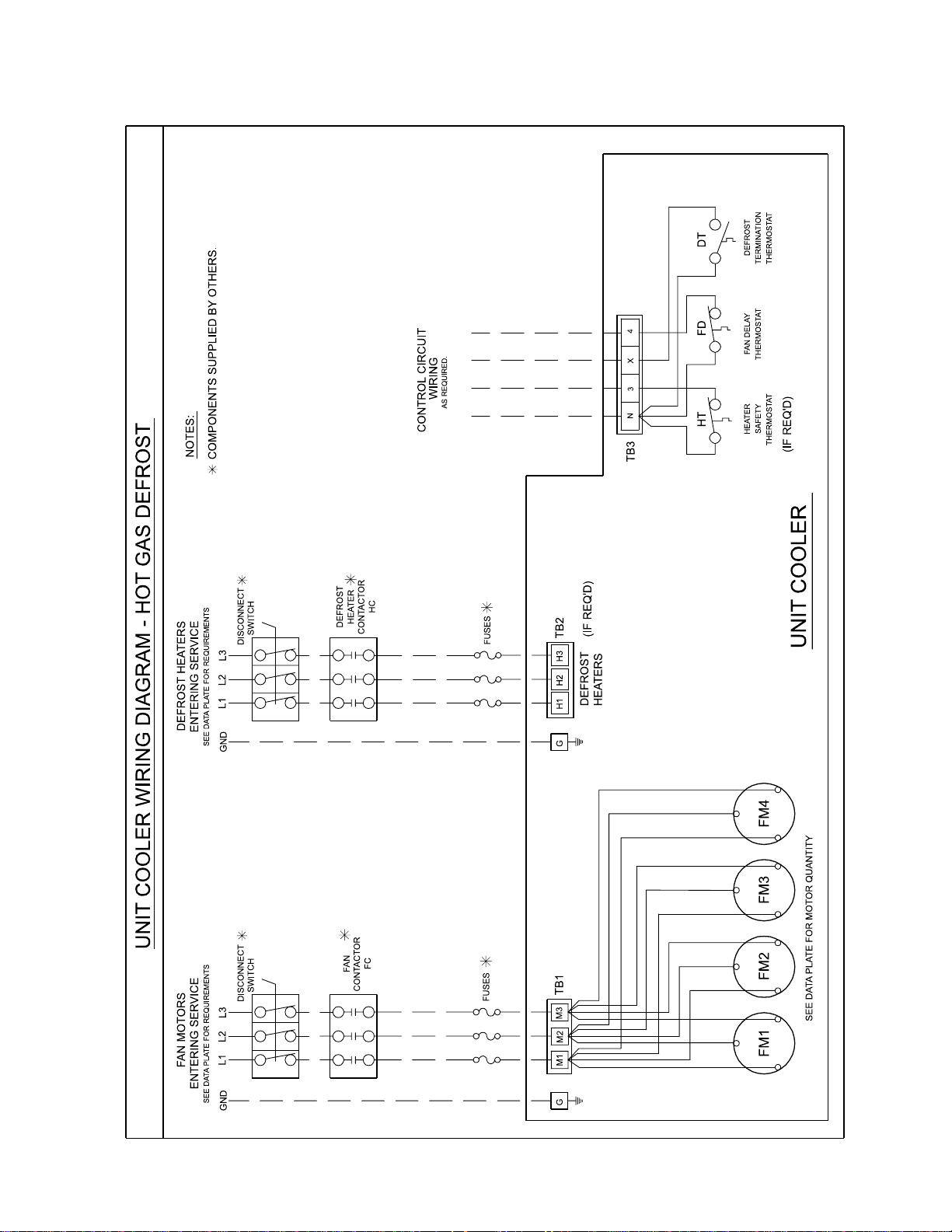
WIRING DIAGRAM
K30-KHPHG-PDI-2
- 7 -
03/22/11
KHP 60Hz
Page 8
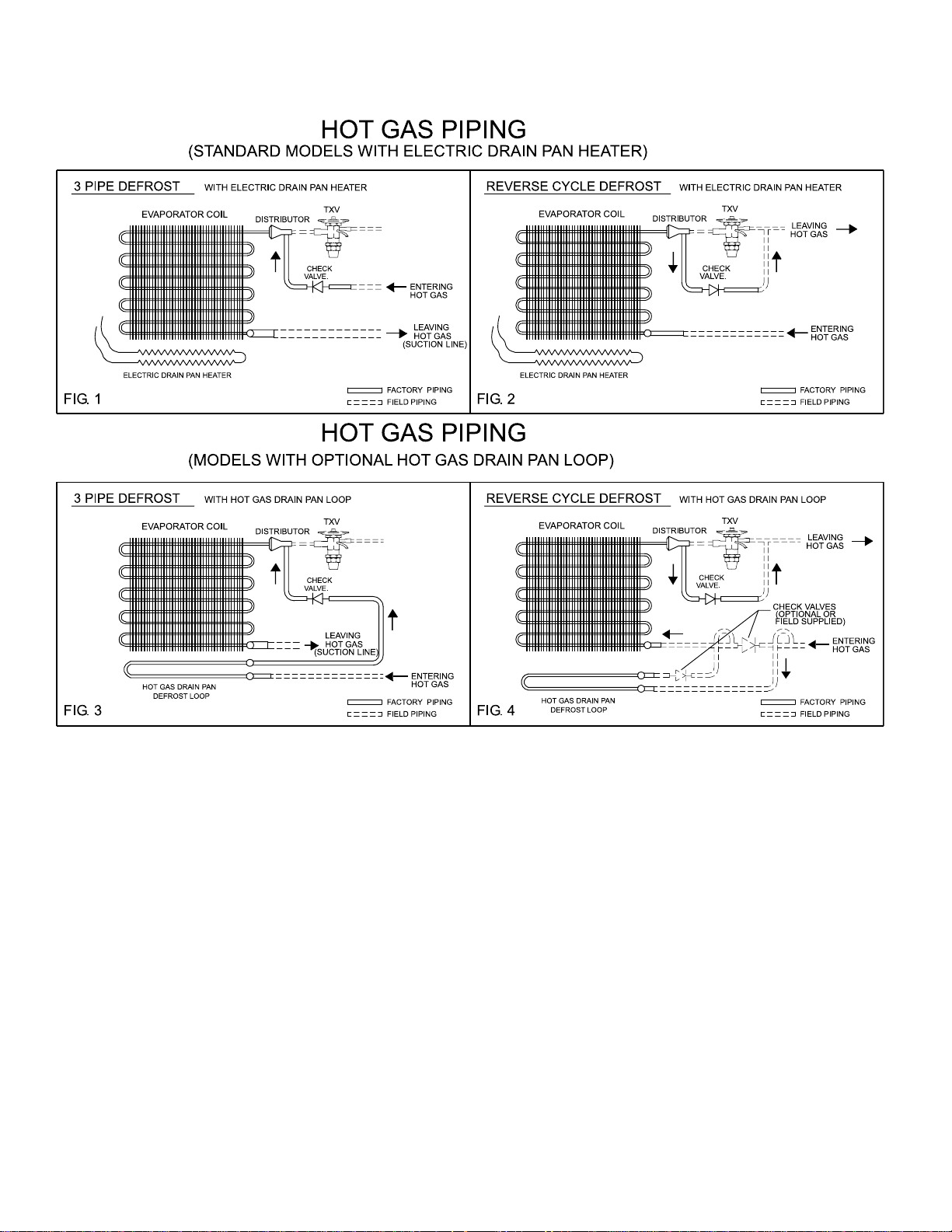
PIPING SCHEMATIC
K30-KHPHG-PDI-2
- 8 -
03/22/11
KHP 60Hz
Page 9

DIMENSIONAL DATA
K30-KHPHG-PDI-2
- 9 -
03/22/11
KHP 60Hz
2 Fan Models
Drain connections 1-1/4” FPT.
3 Fan Models
Page 10

DIMENSIONAL DATA
K30-KHPHG-PDI-2
- 10 -
03/22/11
KHP 60Hz
3 Fan (Long) Models
Drain connections 1-1/4” FPT.
4 Fan Models
Page 11

SPECIFICATIONS -
K30-KHPHG-PDI-2
- 11 -
03/22/11
KHP 60Hz
Medium Temperature Models - 6 F.P.I.
Medium Temp. 6 FPI Models 068M# 081M# 092M# 108M# 123M# 135M# 162M# 181M# 221M# 243M# 271M#
Number Of Fans 2 2 2 2 3 3 3 3 4 4 4
Distributor Conn.
(OD Sweat)
Side Port Conn. 3 Pipe
(OD Sweat)
Side Port Conn. Reverse Cycle
(OD Sweat)
Drain Pan
Loop Conn. (OD Sweat)
Suction Conn.
(OD Sweat)
Approx. Net Weight LB. (KG)
Low Temperature Models - 6 F.P.I.
Low Temp. 6 FPI Models 065L# 078L# 089L# 094L# 118L# 134L# 143L# 161L# 175L# 198L# 216L# 228L#
Number Of Fans 2 2 2 2 3 3 3 3 4 4 4 4
Distributor Conn.
(OD Sweat)
Side Port Conn. 3 Pipe
(OD Sweat)
Side Port Conn. Reverse Cycle
(OD Sweat)
Drain Pan
Loop Conn. (OD Sweat)
Suction Conn.
(OD Sweat)
Approx. Net Weight LB. (KG)
Inches
(mm)
Inches
(mm)
Inches
(mm)
Inches
(mm)
Inches
(mm)
Inches
(mm)
Inches
(mm)
Inches
(mm)
Inches
(mm)
Inches
(mm)
1-1/8
(29)
7/8
(22)
7/8
(22)
1-3/8
(35)
1-3/8
(35)
689
(313)
1-3/8
(35)
1-1/8
(29)
1-1/8
(29)
1-3/8
(35)
2-1/8
(54)
689
(313)
1-3/8
(35)
1-1/8
(29)
1-1/8
(29)
1-3/8
(35)
1-5/8
(41)
731 (332)
1-3/8
(35)
1-1/8
(29)
1-1/8
(29)
1-3/8
(35)
2-1/8
(54)
731
(332)
6 F.P.I. MODELS
1-3/8
(35)
1-1/8
(29)
1-1/8
(29)
1-3/8
(35)
1-5/8
(41)
774
(352)
1-3/8
(35)
1-1/8
(29)
1-1/8
(29)
1-3/8
(35)
2-1/8
(54)
774
(352)
1-3/8
(35)
1-1/8
(29)
1-1/8
(29)
1-3/8
(35)
2-1/8
(54)
816
(371)
1-3/8
(35)
1-1/8
(29)
1-1/8
(29)
1-3/8
(35)
2-1/8
(54)
816
(371)
1-3/8
(35)
1-1/8
(29)
1-1/8
(29)
1-5/8
(41)
2-5/8
(67)
1049
(477)
1-3/8
(35)
1-1/8
(29)
1-1/8
(29)
1-5/8
(41)
2-1/8
(54)
1049
(477)
1-5/8
(41)
1-3/8
(35)
1-3/8
(35)
1-5/8
(41)
2-5/8
(67)
1113
(507)
1-3/8
(35)
1-1/8
(29)
1-1/8
(29)
1-5/8
(41)
2-1/8
(54)
1113
(507)
1-5/8
(41)
1-3/8
(35)
1-3/8
(35)
1-5/8
(41)
2-5/8
(67)
1177
(535)
1-3/8
(35)
1-1/8
(29)
1-1/8
(29)
1-5/8
(41)
2-1/8
(54)
1177
(535)
1-3/8
(35) **
1-3/8
(35)
1-3/8
(35)
1-5/8
(41)
2-5/8
(67)
1272
(577)
1-3/8
(35)
1-3/8
(35)
1-1/8
(29)
1-5/8
(41)
2-1/8
(54)
1272
(577)
(41) *
(659)
1-5/8
(41)
1-5/8
(41)
1-3/8
(35)
1-5/8
2-5/8
(67)
1452
1-3/8
(35)
1-3/8
(35)
1-1/8
(29)
1-5/8 *
(41)
2-5/8
(67)
1558
(707)
1-5/8
(41)
1-5/8
(41)
1-3/8
(35)
1-5/8
(41) *
3-1/8
(80)
1558
(707)
1-3/8
(35)
1-3/8
(35)
1-1/8
(29)
1-5/8 *
(41)
2-5/8
(67)
1664
(755)
1-5/8
(41)
1-5/8
(41)
1-3/8
(35)
1-5/8
(41) *
3-1/8
(80)
1664
(755)
1-5/8
(41)
1-3/8
(35)
1-3/8
(35)
1-5/8 *
(41)
2-5/8
(67)
1876
(851)
1-5/8
(41)
1-5/8
(41)
1-3/8
(35)
1-5/8
(41) *
3-1/8
(80)
1876
(851)
* Drain pan loop will have connections at opposite ends of the unit.
** Reverse Cycle 1-3/8 (35), 3 -Pipe 1-5/8 (41).
Note: Distributor and / or circuiting may change with each application.
Page 12
SPECIFICATIONS -
K30-KHPHG-PDI-2
- 12 -
03/22/11
KHP 60Hz
Medium Temperature Models - 4 F.P.I.
Medium Temp. 4 FPI Models 059P# 072P# 083P# 091P# 109P# 122P# 137P# 150P# 164P# 200P# 222P# 256P#
Number Of Fans 2 2 2 2 3 3 3 3 3 4 4 4
Distributor Conn.
(OD Sweat)
Side Port Conn. 3 Pipe
(OD Sweat)
Side Port Conn. Reverse Cycle
(OD Sweat)
Drain Pan
Loop Conn. (OD Sweat)
Suction Conn.
(OD Sweat)
Approx. Net Weight LB. (KG)
Low Temperature Models - 4 F.P.I.
Low Temp. 4 FPI Models 055V# 066V# 076V# 087V# 100V# 114V# 127V# 145V# 172V# 187V# 217V#
Number Of Fans 2 2 2 2 3 3 3 3 4 4 4
Distributor Conn.
(OD Sweat)
Side Port Conn. 3 Pipe
(OD Sweat)
Side Port Conn. Reverse Cycle
(OD Sweat)
Drain Pan
Loop Conn. (OD Sweat)
Suction Conn.
(OD Sweat)
Approx. Net Weight LB. (KG) 678 (307)
Inches
(mm)
Inches
(mm)
Inches
(mm)
Inches
(mm)
Inches
(mm)
Inches
(mm)
Inches
(mm)
Inches
(mm)
Inches
(mm)
Inches
(mm)
1-1/8
(29)
7/8
(25)
7/8
(25)
1-3/8
(35)
1-3/8
(35)
689
(313)
1-3/8
(35)
1-1/8
(29)
1-1/8
(29)
1-3/8
(35)
2-1/8
(54)
1-1/8
(29)
7/8
(25)
7/8
(25)
1-3/8
(35)
1-5/8
(41)
731
(332)
1-3/8
(35)
1-1/8
(29)
1-1/8
(29)
1-3/8
(35)
2-1/8
(54)
710
(322)
4 F.P.I. MODELS
1-1/8
(29)
7/8
(25)
7/8
(25)
1-3/8
(35)
1-5/8
(41)
774
(352)
1-3/8
(35)
1-1/8
(29)
1-1/8
(29)
1-3/8
(35)
2-1/8
(54)
742
(337)
1-3/8
(35)
1-1/8
(29)
1-1/8
(29)
1-3/8
(35)
1-5/8
(41)
816
(371)
1-3/8
(35)
1-1/8
(29)
1-1/8
(29)
1-3/8
(35)
2-1/8
(54)
784
(356)
1-3/8
(35)
1-1/8
(29)
1-1/8
(29)
1-5/8
(41)
2-1/8
(54)
1049
(477)
1-3/8
(35)
1-1/8
(29)
1-1/8
(29)
1-5/8
(41)
2-1/8
(54)
1113
(507)
1-3/8
(35)
1-1/8
(29)
1-1/8
(29)
1-5/8
(41)
2-5/8
(67)
1018
(461)
1-5/8
(41)
1-3/8
(35)
1-1/8
(29)
1-5/8
(41)
2-5/8
(67)
1071
(485)
1-3/8
(35)
1-1/8
(29)
1-1/8
(29)
1-5/8
(41)
2-1/8
(54)
1177
(535)
1-5/8
(41)
1-3/8
(35)
1-1/8
(29)
1-5/8
(41)
2-5/8
(67)
1124
(510)
1-3/8
(35)
1-1/8
(29)
1-1/8
(29)
1-5/8
(41)
2-1/8
(54)
1272
(577)
1-3/8
(35) **
1-3/8
(35)
1-3/8
(35)
1-5/8
(41)
2-5/8
(67)
1219
(552)
1-3/8
(35)
1-1/8
(29)
1-1/8
(29)
1-5/8
(41)
2-1/8
(54)
1452
(659)
1-3/8
1-3/8
1-1/8
1-5/8
(41) *
2-5/8
1558
(707)
1-5/8
(41)
1-5/8
(41)
1-3/8
(35)
1-5/8
(41) *
2-5/8
(67)
1505
(683)
(35)
(35)
(29)
(67)
1-3/8
(35)
1-3/8
(35)
1-1/8
(29)
1-5/8
(41) *
2-5/8
(67)
1664
(755)
1-5/8
(41)
1-5/8
(41)
1-3/8
(35)
1-5/8
(41) *
3-1/8
(80)
1601
(726)
1-5/8
(41)
1-3/8
(35)
1-3/8
(35)
1-5/8
(41) *
2-5/8
(67)
1876
(851)
1-5/8
(41)
1-5/8
(41)
1-3/8
(35)
1-5/8
(41) *
3-1/8
(80)
1780
(808)
* Drain pan loop will have connections at opposite ends of the unit.
** Reverse Cycle 1-3/8 (35), 3 -Pipe 1-5/8 (41).
Note: Distributor and / or circuiting may change with each application.
Page 13

INSTALLATION INSTRUCTIONS
K30-KHPHG-PDI-2
- 13 -
03/22/11
KHP 60Hz
The installation and start-up of evaporators should only
be performed by qualied refrigeration mechanics.
This equipment should be installed in accordance with
all applicable codes, ordinances and local by-laws
INSPECTION
Inspect all equipment before unpacking for visible signs
of damage or loss. Check shipping list against material
received to ensure shipment is complete.
IMPORTANT: Remember, you, the consignee, must
make any claim necessary against the transportation
company. Shipping damage or missing parts, when
discovered at the outset, will prevent later unnecessary
and costly delays.
If damage or loss during transport is evident, make
claim to carrier, as this will be their responsibility,
not the manufacturer’s.
Should carton be damaged, but damage to equipment
is not obvious, a claim should be led for “concealed
damage” with the carrier.
IMPORTANT: The electrical characteristics of the
unit should be checked at this time to make sure they
correspond to those ordered and to electrical power
available at the job site.
Save all shipping papers, tags and instruction sheets for
reference by installer and owner.
LOCATION
The unit location in the room should be selected to
ensure uniform air distribution throughout the entire
space to be refrigerated. Be sure that the unit does
not draw air in, or blow directly out, through an opened
door and that the product does not obstruct the free
circulation of air.
Consideration should be given to the coil location in
order to minimize the piping run length to the condensing
unit and oor drain
CLEARANCES
This evaporator draws air through the coil and
discharges air from the fan side, and thus adequate
clearance should be made on the entering face of the
coil to ensure even unrestricted air ow through the coil.
This distance should be equal to the height of the coil or
more.
Ensure enough room is left at the ends of the coil for
servicing.
MOUNTING
This evaporator is supplied with shipping legs to allow
units to be shipped in an upright position. Units can be
lifted into place with shipping skid attached to mounting
legs.
Hanger brackets take up to 5/8” (15.9 mm) hanger
rods. After the evaporator is hung in place, remove the
bolts attaching the skid to the legs.
DRAIN LINE
If the evaporator is mounted ush to ceiling, the
staggered hanger will provide a positive pitch for
drainage.
If units are suspended below the ceiling, the installer
must provide adequate pitch to the unit by adjusting
the location of the hanger rod nuts.
Note: Check for adequate drainage by pouring water
into the drain pan.
Ensure that the drain pan has sufcient slope
for proper drainage (prevention of ice build up /
blockage in pan).
Insulated copper tube should be run from the drain
connection, sloping at least 4” (102mm) per foot. A
trap located outside of the room should be provided
to prevent warm air entering through the tubing.
Connection should be made to proper drainage
facilities that comply with local regulations.
If room temperatures are below freezing, it is
necessary to heat the drain line to prevent condensate
from
freezing in the drain line. Electric heating cable or
electric tape (by others) is used for this purpose. The
drain line heater should be connected for continuous
operation; it is also recommended that the drain line
be insulated. A heat output of 20 watts per lineal foot of
1” (25mm) drain line in a 0°F (-18 °C) room is usually
satisfactory. 115 volt cable and tape is available from
your local refrigeration wholesaler. Two 115 volts
heaters (by others) of the same wattage may be wired
in series for use on 230 volt system.
Page 14

INSTALLATION INSTRUCTIONS (cont’d)
K30-KHPHG-PDI-2
- 14 -
03/22/11
KHP 60Hz
PIPING
Refrigerant line sizes are important and may not be
the same size as the coil connections (depends on
the length of run). If in doubt, consult “Recommended
refrigerant line sizes” charts.
WIRING
Wire system in accordance with governing standards
and local codes. Enclosed typical wiring diagrams are
for reference only. Refer to unit data plate for operating
current, minimum ampacity and maximum fuse sizing
for fan motors.
NOTE: Electrical wiring is to be sized in accordance
with minimum ampacity rating.
For ease of identifying the proper wiring terminals, unit
wiring is colour coded and terminal block connections
are identied. When fan delay thermostats (combination fan delay and defrost termination) are installed, on
start-up, the fans do not operate until the coil temperature is reduced to approximately 20 °F (-6.7 °C). It is
normal for the fans to cycle a few times until the room
temperature is brought down. At higher evaporating
temperatures this control is of an adjustable type, and
proper adjustment is required.
The defrost termination control is adjustable and
may be set at a minimum of 40 °F (4.4 °C) (fully CW)
to a maximum of 75 °F (23.8 °C) (fully CCW). Normal
setting is 55 °F (12.8 °C). This can be increased if the
defrost heaters are terminated too soon (frost still left)
or if terminated too long (steaming of coil). Time clock
should be set for a fail-safe termination of approximately 45 minutes.
A hinged end panel provides quick access to the electrical compartment.
SYSTEM CHECK
Before Start-Up:
1. All wiring should be in accordance with local codes.
2. All refrigerant lines should be properly sized.
3. Electric defrost systems should include a liquid line
solenoid valve.
4. Thorough evacuation and dehydration has been
performed.
5. The suction, discharge and receiver service valves
must be open.
6. The system should include a liquid line drier moisture
indicator and suction lter.
7. Pour enough water into the drain pan to allow a good
check on drainage and seal the trap.
After Start-Up:
1. If necessary, temporarily by-pass fan delay control to
run fans until room temp is lowered. (Run jumper wire
from terminal N to F on circuit terminal block).
2. Check the compressor oil level to ensure the correct
oil charge.
3. Be sure that the expansion valve is properly set to
provide the correct amount of superheat (should be
around 70% of operating T.D.)
4. Heavy moisture loads are usually encountered when
starting the system for the rst time. If the coil
temperature is below freezing, this will cause a
rapid build-up of frost on the coil. During the initial pull
down, frost build-up should be watched and defrosted
manually as required.
5. Check for proper evaporator fan blade rotation.
MAINTENANCE
1. Periodic checking and cleaning of the coil surface
when necessary should be done, using a whisk or
brush. Drain pans are hinged to provide convenient
access to the inside coil surface (except hot gas loop
pans).
2. Ensure coil and pan does not have any excessive ice
build-up from improper defrost operation. Any build-up
of ice can cause ns and refrigerant tubes to be
crushed. When replacing heater elements, rst
remove heater slot covers and heater clips
3. Motors are permanently lubricated type and require
no further lubrication.
Page 15

KHP
K30-KHPHG-PDI-2
- 15 -
03/22/11
CAPACITY DATA
R404A
-
60Hz
HIGH VELOCITY MODELS
Medium Temperature - 6 F.P.I. with 3 HP Motor @ 0” External Static Pressure
Medium Temp. Models 068M# 081M# 092M# 108M# 123M# 135M# 162M# 181M# 221M# 243M# 271M#
Capacity
BTUH
(WATTS)
Air Flow CFM (L/S)
Refrigerant Charge *
R404A
Low Temperature - 6 F.P.I. with 3 HP Motor @ 0” External Static Pressure
Low Temp. Models 065L# 078L# 089L# 094L# 118L# 134L# 143L# 161L# 175L# 198L# 216L# 228L#
Capacity
BTUH
(WATTS)
Air Flow CFM (L/S)
Refrigerant Charge **
R404A
Evap
Temp.
°F (°C)
Evap
Temp.
°F (°C)
10
(-12.2)
LB. (KG)
0
(-17.8)
-10
(-23.3)
-20
(-26.1)
-30
(-34.4)
-40
(-40)
LB.
(KG)
79000
(23139)
23800
(11231)
76000
(22260)
72800
(21323)
68000
(19917)
63200
(18511)
57600
(16871)
23800
(11231)
21
(10)
20
(9)
97000
(28411)
22800
(10759)
96100
(28148)
92000
(26947)
86000
(25189)
79900
(23403)
72800
(21323)
22800
(10759)
29
(13)
27
(12)
112000
(32805)
(10240)
105100
(30784)
100600
(29466)
94000
(27533)
87300
(25570)
79600
(23315)
21700
(10240)
36
(16)
21700
33
(15)
117300
(34357)
112400
(32922)
105000
(30755)
97500
(28558)
88900
(26039)
20800
(9816)
43
(19)
122000
(35734)
20800
(9816)
40
(18)
139700
(40918)
133800
(39190)
125000
(36613)
116100
(34006)
105900
(31018)
34200
(16139)
43
(19)
146000
(42763)
34200
(16139)
40
(18)
164300
(48123)
157300
(46073)
147000
(43056)
136600
(40010)
124500
(36466)
32600
(15384)
(24)
54
164000
(48036)
32600
(15384)
50
(23)
183300
(53689)
175500
(51404)
164000
(48036)
152400
(44638)
138900
(40684)
31200
(14723)
64
(29)
182000
(53308)
31200
(14723)
60
(27)
201200
(58931)
192600
(56413)
180000
(52722)
167200
(48973)
152500
(44667)
32900
(15526)
95
(43)
205000
(60045)
32900
(15526)
88
(40)
204500
(59898)
195800
(57350)
183000
(53601)
170000
(49793)
155000
(45400)
47200
(22274)
84
(38)
251000
(73518)
45500
(21471)
98
(45)
239200
(70062)
229000
(67074)
214000
(62681)
198800
(58229)
181300
(53103)
45500
(21471)
105
(48)
277000
(81133)
43800
(20669)
118
(54)
268200
(78556)
256800
(75217)
240000
(70296)
223000
(65317)
203300
(59547)
43800
(20669)
118
(54)
307000
(89920)
40900
(19301)
157
(71)
282800
(82832)
270700
(79288)
253000
(74104)
235000
(68832)
214300
(62768)
40900
(19301)
157
(71)
Medium Temperature - 4 F.P.I. with 3 HP Motor @ 0” External Static Pressure
Medium Temp. Models 059P# 072P# 083P# 091P# 109P# 122P# 137P# 150P# 164P# 200P# 222P# 256P#
Capacity
BTUH
(WATTS)
Air Flow
Refrigerant Charge *
R404A
Evap
Temp.
°F (°C)
CFM
(L/S)
10
(-12.2)
LB.
(KG)
67000
(19624)
24400
(11514)
20
(9)
83000
(24311)
23600
(11137)
27
(12)
94000
(27533)
22800
(10759)
33
(15)
107000
(31340)
21900
(10335)
40
(18)
125000
(36613)
35400
(16705)
40
(18)
147000
(43056)
34100
(16092)
50
(23)
161000
(47157)
32900
(15526)
56
(25)
165000
(48329)
35400
(16705)
74
(33)
187000
(54772)
34300
(16186)
88
(40)
218000
(63852)
47200
(22274)
98
(45)
246000
(72053)
45800
(21613)
118
(54)
288000
(84355)
43200
(20386)
157
(71)
Low Temperature - 4 F.P.I. with 3 HP Motor @ 0” External Static Pressure
Low Temp. Models 055V# 066V# 076V# 087V# 100V# 114V# 127V# 145V# 172V# 187V# 217V#
Capacity
BTUH
(WATTS)
Air Flow
Refrigerant Charge **
Evap
Temp.
°F (°C)
CFM
(L/S)
R404A
Capacities rated using R404A with 10°F (5.6°C) TD & 100°F (38°C) liquid temperature.
Capacities at other TD within a range of 8 to 15 °F (4.4 to 8.3°C) are directly proportional to TD, or use formula: Capacity = Rated capacity ÷ 10 x TD.
For capacities at TD outside of range 8 to 15 °F (4.4 to 8.3°C), or liquid temperature lower than 75°F (24°), consult factory.
* Estimated, based on R404A at +25° S.S.T. with coil 30% full. ** Estimated, based on R404A at -20° S.S.T. with coil 30% full.
Derate capacity by 0.92 and CFM by .85 for Throw Booster Option # = T / G / H / R
‡ When using R407C, the factor above is to be used when matching to condensing units with Dew Point ratings. This factor will ensure that proper
system balancing will occur to compensate for glide to t the application. If the system is sized correctly, one may expect a slight increase in system
capacity, along with slightly higher saturated suction temperatures.
Average Air Throw - ft (m)
STANDARD FAN AND MOTOR OPTIONAL THROW BOOSTER
110 (33) 150 (46)
0
(-17.8)
-10
(-23.3)
-20
(-26.1)
-30
(-34.4)
-40
(-40)
LB.
(KG)
65900
(19302)
63100
(18482)
59000
(17281)
54800
(16051)
50000
(14645)
24400
(11514)
21
(10)
79300
(23227)
76000
(22260)
71000
(20796)
66000
(19331)
60100
(17603)
23600
(11137)
29
(13)
95000
(27826)
91000
(26654)
85000
(24897)
79000
(23139)
72000
(21089)
22800
(10759)
36
(16)
107300
(31428)
102700
(30081)
96000
(28118)
89200
(26127)
81300
(23813)
21900
(10335)
43
(19)
Correction Factors for Other Refrigerants Use
R22
0.95 0.90 1.00 0.90
†
R134a
124100
(36349)
118800
(34797)
111000
(32512)
103100
(30198)
94000
(27533)
35400
(16705)
(19)
43
R507
146400
(42881)
140200
(41065)
131000
(38370)
121700
(35646)
111000
(32512)
34100
(16092)
54
(24)
R404A
153100
(44843)
146600
(42939)
137000
(40127)
127300
(37286)
116000
(33976)
32900
(15526)
(29)
64
181100
(53044)
173300
(50760)
162000
(47450)
150500
(44081)
137200
(40186)
34300
(16186)
95
(43)
Values Multiplied By:
R407C
‡
215700
(63179)
206500
(60484)
193000
(56530)
179300
(52517)
163500
(47889)
47200
(22274)
105
(48)
241400
(70706)
231100
(67689)
216000
(63266)
200700
(58785)
183000
(53601)
45800
(21613)
126
(57)
270500
(79229)
258900
(75832)
242000
(70882)
224800
(65844)
205000
(60045)
43200
(20386)
† Measured in open space. Actual throw may be less in
real applications.
157
(71)
Page 16

KHP
K30-KHPHG-PDI-2
- 16 -
03/22/11
CAPACITY DATA
R404A
-
60Hz
HIGH VELOCITY MODELS
Medium Temperature - 6 F.P.I. with 3 HP Motor @ .25” External Static Pressure
Medium Temp. Models 068M# 081M# 092M# 108M# 123M# 135M# 162M# 181M# 221M# 243M# 271M#
Capacity
BTUH
(WATTS)
Air Flow CFM (L/S)
Refrigerant Charge *
R404A
Low Temperature - 6 F.P.I. with 3 HP Motor @ .25” External Static Pressure
Low Temp. Models 065L# 078L# 089L# 094L# 118L# 134L# 143L# 161L# 175L# 198L# 216L# 228L#
Capacity
BTUH
(WATTS)
Air Flow CFM (L/S)
Refrigerant Charge **
R404A
Evap
Temp.
°F (°C)
Evap
Temp.
°F (°C)
10
(-12.2)
LB. (KG)
0
(-17.8)
-10
(-23.3)
-20
(-26.1)
-30
(-34.4)
-40
(-40)
LB.
(KG)
76000
(22260)
22300
(10523)
(9)
73800
(21616)
70600
(20679)
66000
(19331)
61300
(17955)
55900
(16373)
22300
(10523)
21
(10)
20
93000
(27240)
21200
(10004)
92800
(27181)
88800
(26010)
83000
(24311)
77100
(22583)
70300
(20591)
21200
(10004)
29
(13)
27
(12)
107000
(31340)
20100
(9485)
101700
(29788)
97400
(28528)
91000
(26654)
84500
(24750)
77100
(22583)
20100
(9485)
36
(16)
33
(15)
117000
(34269)
114000
(33391)
109100
(31955)
102000
(29876)
94800
(27767)
86400
(25307)
19200
(9060)
43
(19)
19200
(9060)
40
(18)
135200
(39600)
129500
(37931)
121000
(35441)
112400
(32922)
102500
(30022)
31700
(14959)
141000
(41299)
31700
(14959)
40
(18)
157600
(46161)
150900
(44199)
141000
(41299)
131000
(38370)
119400
(34972)
30100
(14204)
43
(19)54(24)
158000
(46278)
30100
(14205)
50
(23)
175500
(51404)
168000
(49207)
157000
(45985)
145900
(42734)
133000
(38956)
28700
(13544)
(29)
64
174000
(50965)
28700
(13544)
60
(27)
192200
(56295)
184000
(53894)
172000
(50379)
159800
(46805)
145700
(42676)
30200
(14251)
95
(43)84(38)
196000
(57408)
30200
(14251)
88
(40)
197800
(57936)
189400
(55475)
177000
(51843)
164400
(48153)
149900
(43906)
43600
(20575)
240000
(70296)
41900
(19773)
98
(45)
230200
(67426)
220400
(64555)
206000
(60337)
191400
(56061)
174500
(51111)
41900
(19773)
105
(48)
264000
(77326)
40300
(19018)
118
(54)
257000
(75275)
246100
(72083)
230000
(67367)
213700
(62593)
194800
(57057)
40300
(19018)
118
(54)
291000
(85234)
37500
(17696)
157
(71)
271600
(79552)
260000
(76154)
243000
(71175)
225700
(66108)
205800
(60279)
37500
(17696)
157
(71)
Medium Temperature - 4 F.P.I. with 3 HP Motor @ .25” External Static Pressure
Medium Temp. Models 059P# 072P# 083P# 091P# 109P# 122P# 137P# 150P# 164P# 200P# 222P# 256P#
Capacity
BTUH
(WATTS)
Air Flow
Refrigerant Charge *
R404A
Evap
Temp.
°F (°C)
CFM
(L/S)
10
(-12.2)
LB.
(KG)
65000
(19039)
23000
(10854)
20
(9)
81000
(23725)
22100
(10429)
27
(12)
91000
(26654)
21200
(10004)
33
(15)
102000
(29876)
20300
(9580)
40
(18)
121000
(35441)
33100
(15620)
40
(18)
141000
(41299)
31700
(14959)
50
(23)
154000
(45107)
30400
(14346)
56
(25)
159000
(46571)
32700
(15431)
74
(33)
177000
(51843)
31600
(14912)
88
(40)98(45)
210000
(61509)
43600
(20575)
235000
(68832)
42200
(19914)
118
(54)
274000
(80255)
39700
(18734)
157
(71)
Low Temperature - 4 F.P.I. with 3 HP Motor @ .25” External Static Pressure
Low Temp. Models 055V# 066V# 076V# 087V# 100V# 114V# 127V# 145V# 172V# 187V# 217V#
0
(-17.8)
-10
Capacity
BTUH
(WATTS)
Air Flow
Refrigerant Charge **
Evap
Temp.
°F (°C)
CFM
(L/S)
R404A
Capacities rated using R404A with 10°F (5.6°C) TD & 100°F (38°C) liquid temperature.
Capacities at other TD within a range of 8 to 15 °F (4.4 to 8.3°C) are directly proportional to TD, or use formula: Capacity = Rated capacity ÷ 10 x TD.
For capacities at TD outside of range 8 to 15 °F (4.4 to 8.3°C), or liquid temperature lower than 75°F (24°), consult factory.
* Estimated, based on R404A at +25° S.S.T. with coil 30% full. ** Estimated, based on R404A at -20° S.S.T. with coil 30% full.
Derate capacity by 0.92 and CFM by .85 for Throw Booster Option # = T / G / H / R
(-23.3)
-20
(-26.1)
-30
(-34.4)
-40
(-40)
LB.
(KG)
64800
(18980)
62100
(18189)
58000
(16988)
53900
(15787)
49100
(14381)
23000
(10854)
21
(10)
Correction Factors for Other Refrigerants Use
‡ When using R407C, the factor above is to be used when matching to condensing units with Dew Point ratings. This factor will ensure that proper
system balancing will occur to compensate for glide to t the application. If the system is sized correctly, one may expect a slight increase in system
capacity, along with slightly higher saturated suction temperatures.
Average Air Throw - ft (m)
STANDARD FAN AND MOTOR OPTIONAL THROW BOOSTER
110 (33) 150 (46)
78200
(22905)
74900
(21938)
70000
(20503)
65000
(19039)
59300
(17369)
22100
(10429)
29
(13)
91600
(26830)
87700
(25687)
82000
(24018)
76200
(22319)
69500
(20357)
21200
(10004)
36
(16)
103900
(30432)
99500
(29144)
93000
(27240)
86400
(25307)
78800
(23081)
20300
(9580)
43
(19)
120700
(35353)
115600
(33859)
108000
(31633)
100300
(29378)
91500
(26800)
33100
(15620)
43
(19)
140800
(41240)
134800
(39483)
126000
(36905)
117100
(34299)
106700
(31252)
31700
(14959)
54
(24)
R404A
R22
0.95 0.90 1.00 0.90
†
R134a
R507
† Measured in open space. Actual throw may be less in
real applications.
149800
(43876)
143400
(42002)
134000
(39249)
124500
(36466)
113500
(33244)
30400
(14346)
(29)
64
173200
(50730)
165900
(48592)
155000
(45400)
144000
(42178)
131300
(38458)
31600
(14912)
95
(43)
Values Multiplied By:
R407C
‡
206800
(60572)
198000
(57994)
185000
(54187)
171900
(50350)
156700
(45897)
43600
(20575)
105
(48)
231300
(67748)
221500
(64877)
207000
(60630)
192300
(56325)
175300
(51345)
42200
(19914)
126
(57)
258200
(75627)
247200
(72405)
231000
(67660)
214600
(62856)
195700
(57321)
39700
(18734)
157
(71)
Page 17

KHP
K30-KHPHG-PDI-2
- 17 -
03/22/11
CAPACITY DATA
R404A
-
60Hz
HIGH VELOCITY MODELS
Medium Temperature - 6 F.P.I. with 3 HP Motor @ .50” External Static Pressure
Medium Temp. Models 068M# 081M# 092M# 108M# 123M# 135M# 162M# 181M# 221M# 243M# 271M#
Capacity
BTUH
(WATTS)
Air Flow CFM (L/S)
Refrigerant Charge *
R404A
Low Temperature - 6 F.P.I. with 3 HP Motor @ .50” External Static Pressure
Low Temp. Models 065L# 078L# 089L# 094L# 118L# 134L# 143L# 161L# 175L# 198L# 216L# 228L#
Capacity
BTUH
(WATTS)
Air Flow CFM (L/S)
Refrigerant Charge **
R404A
Evap
Temp.
°F (°C)
Evap
Temp.
°F (°C)
10
(-12.2)
LB.
(KG)
0
(-17.8)
-10
(-23.3)
-20
(-26.1)
-30
(-34.4)
-40
(-40)
LB.
(KG)
73000
(21382)
20400
(9627)
20
(9)
72600
(21265)
69600
(20386)
65000
(19039)
60400
(17691)
55100
(16139)
20400
(9627)
21
(10)
89000
(26068)
19200
(9060)
27
(12)
88300
(25863)
84500
(24750)
79000
(23139)
73400
(21499)
66900
(19595)
19200
(9060)
29
(13)36(16)
101000
(29583)
18300
(8636)
(15)
97200
(28470)
93100
(27269)
87000
(25482)
80800
(23666)
73700
(21587)
18300
(8636)
33
111000
(32512)
17500
(8258)
(18)
108400
(31750)
103800
(30403)
97000
(28411)
90100
(26390)
82200
(24076)
17500
(8258)
43
(19)
40
134000
(39249)
28900
(13638)
130800
(38311)
125200
(36671)
117000
(34269)
108700
(31838)
99100
(29026)
28900
(13638)
43
(19)
40
(18)
150000
(43935)
(12977)
150900
(44199)
144500
(42324)
135000
(39542)
125400
(36730)
114300
(33478)
27500
(12977)
54
(24)
27500
50 (23)
167600
(49090)
160500
(47010)
150000
(43935)
139400
(40830)
127100
(37228)
26300
(12411)
64
(29)
166000
(48621)
26300
(12411)
60
(27)
181100
(53044)
173300
(50760)
162000
(47450)
150500
(44081)
137200
(40186)
27300
(12883)
(43)
95
184000
(53894)
27300
(12883)
88
(40)
190000
(55651)
181900
(53279)
170000
(49793)
157900
(46249)
144000
(42178)
39500
(18640)
(38)
84
227000
(66488)
37800
(17838)
98
(45)
219000
(64145)
209700
(61421)
196000
(57408)
182100
(53337)
166000
(48621)
37800
(17838)
105
(48)
248000
(72639)
36300
(17130)
118
(54)
242500
(71028)
232200
(68011)
217000
(63559)
201600
(59049)
183800
(53835)
36300
(17130)
118
(54)
272000
(79669)
33700
(15903)
157
(71)
257000
(75275)
246100
(72083)
230000
(67367)
213700
(62593)
194800
(57057)
33700
(15903)
157
(71)
Medium Temperature - 4 F.P.I. with 3 HP Motor @ .50” External Static Pressure
Medium Temp. Models 059P# 072P# 083P# 091P# 109P# 122P# 137P# 150P# 164P# 200P# 222P# 256P#
Capacity
BTUH
(WATTS)
Air Flow
Refrigerant Charge *
R404A
Evap
Temp.
°F (°C)
CFM
(L/S)
10
(-12.2)
LB.
(KG)
62000
(18160)
21200
(10004)
20
(9)
77000
(22553)
20100
(9485)
27
(12)
87000
(25482)
19200
(9060)
33
(15)
97000
(28411)
18500
(8730)
40
(18)
116000
(33976)
30200
(14251)
40
(18)
134000
(39249)
28900
(13638)
50
(23)
147000
(43056)
27700
(13072)
56
(25)
150000
(43935)
29600
(13968)
74
(33)
167000
(48914)
28600
(13496)
88
(40)
199000
(58287)
39500
(18640)
98
(45)
222000
(65024)
38100
(17979)
118
(54)
256000
(74982)
35700
(16847)
157
(71)
Low Temperature - 4 F.P.I. with 3 HP Motor @ .50” External Static Pressure
Low Temp. Models 055V# 066V# 076V# 087V# 100V# 114V# 127V# 145V# 172V# 187V# 217V#
0
-10
-20
-30
-40
61500
(18013)
58900
(17252)
55000
(16110)
51100
(14967)
46600
(13649)
21200
(10004)
21
(10)
(-17.8)
Capacity
BTUH
(WATTS)
Air Flow
Refrigerant Charge **
Evap
Temp.
°F (°C)
CFM
(L/S)
R404A
Capacities rated using R404A with 10°F (5.6°C) TD & 100°F (38°C) liquid temperature.
Capacities at other TD within a range of 8 to 15 °F (4.4 to 8.3°C) are directly proportional to TD, or use formula: Capacity = Rated capacity ÷ 10 x TD.
For capacities at TD outside of range 8 to 15 °F (4.4 to 8.3°C), or liquid temperature lower than 75°F (24°), consult factory.
* Estimated, based on R404A at +25° S.S.T. with coil 30% full. ** Estimated, based on R404A at -20° S.S.T. with coil 30% full.
Derate capacity by 0.92 and CFM by .85 for Throw Booster Option # = T / G / H / R
(-23.3)
(-26.1)
(-34.4)
(-40)
LB.
(KG)
Correction Factors for Other Refrigerants Use
‡ When using R407C, the factor above is to be used when matching to condensing units with Dew Point ratings. This factor will ensure that proper
system balancing will occur to compensate for glide to t the application. If the system is sized correctly, one may expect a slight increase in system
capacity, along with slightly higher saturated suction temperatures.
Average Air Throw - ft (m)
STANDARD FAN AND MOTOR OPTIONAL THROW BOOSTER
110 (33) 150 (46)
74900
(21938)
71700
(21001)
67000
(19624)
62200
(18218)
56700
(16607)
20100
(9485)
29
(13)
88300
(25863)
84500
(24750)
79000
(23139)
73400
(21499)
66900
(19595)
19200
(9060)
36
(16)
98300
(28792)
94200
(27591)
88000
(25775)
81800
(23959)
74500
(21821)
18500
(8730)
43
(19)
115100
(33713)
110200
(32278)
103000
(30169)
95700
(28031)
87200
(25541)
30200
(14251)
43
(19)
133000
(38956)
127300
(37286)
119000
(34855)
110600
(32395)
100800
(29524)
28900
(13638)
54
(24)
R404A
R22
0.95 0.90 1.00 0.90
†
R134a
R507
† Measured in open space. Actual throw may be less in
real applications.
143100
(41914)
137000
(40127)
128000
(37491)
118900
(34826)
108400
(31750)
27700
(13072)
(29)
64
164300
(48123)
157300
(46073)
147000
(43056)
136600
(40010)
124500
(36466)
28600
(13496)
95
(43)
Values Multiplied By:
R407C
‡
195600
(57291)
187300
(54860)
175000
(51258)
162600
(47626)
148200
(43408)
39500
(18640)
105
(48)
219000
(64145)
209700
(61421)
196000
(57408)
182100
(53337)
166000
(48621)
38100
(17979)
126
(57)
243600
(71350)
233300
(68334)
218000
(63852)
202500
(59312)
184600
(54069)
35700
(16847)
157
(71)
Page 18

ELECTRICAL DATA -
K30-KHPHG-PDI-2
- 18 -
03/22/11
KHP
MODEL FPI
KHP068M#-T3A
KHP081M#-T3A 2 3 18.4 25.1 30 7350 18.5 23.1 25
KHP092M#-T3A 2 3 18.4 25.1 30 7350 18.5 23.1 25
KHP108M#-T3A 2 3 18.4 25.1 30 7350 18.5 23.1 25
KHP123M#-T3A 3 3 27.6 35.1 40 10500 26.4 33.0 35
KHP135M#-T3A 3 3 27.6 35.1 40 10500 26.4 33.0 35
KHP162M#-T3A 3 3 27.6 35.1 40 10500 26.4 33.0 35
KHP181M#-T3A 3+ 3 27.6 35.1 40 10800 27.1 33.9 35
KHP221M#-T3A 4 3 36.8 45.1 50 14100 35.4 44.2 50
KHP243M#-T3A 4 3 36.8 45.1 50 14100 35.4 44.2 50
KHP271M#-T3A 4 3 36.8 45.1 50 14100 35.4 44.2 50
KHP065L#-T3A 2 3 18.4 25.1 30 7350 18.5 23.1 25
KHP078L#-T3A 2 3 18.4 25.1 30 7350 18.5 23.1 25
KHP089L#-T3A 2 3 18.4 25.1 30 7350 18.5 23.1 25
KHP094L#-T3A 2 3 18.4 25.1 30 7350 18.5 23.1 25
KHP118L#-T3A 3 3 27.6 35.1 40 10500 26.4 33.0 35
KHP134L#-T3A 3 3 27.6 35.1 40 10500 26.4 33.0 35
KHP143L#-T3A 3 3 27.6 35.1 40 10500 26.4 33.0 35
KHP161L#-T3A 3+ 3 27.6 35.1 40 10800 27.1 33.9 35
KHP175L#-T3A 4 3 36.8 45.1 50 14100 35.4 44.2 50
KHP198L#-T3A 4 3 36.8 45.1 50 14100 35.4 44.2 50
KHP216L#-T3A 4 3 36.8 45.1 50 14100 35.4 44.2 50
KHP228L#-T3A 4 3 36.8 45.1 50 14100 35.4 44.2 50
KHP059P#-T3A
KHP072P#-T3A 2 3 18.4 25.1 30 7350 18.5 23.1 25
KHP083P#-T3A 2 3 18.4 25.1 30 7350 18.5 23.1 25
KHP091P#-T3A 2 3 18.4 25.1 30 7350 18.5 23.1 25
KHP109P#-T3A 3 3 27.6 35.1 40 10500 26.4 33.0 35
KHP122P#-T3A 3 3 27.6 35.1 40 10500 26.4 33.0 35
KHP137P#-T3A 3 3 27.6 35.1 40 10500 26.4 33.0 35
KHP150P#-T3A 3+ 3 27.6 35.1 40 10800 27.1 33.9 35
KHP164P#-T3A 3+ 3 27.6 35.1 40 10800 27.1 33.9 35
KHP200P#-T3A 4 3 36.8 45.1 50 14100 35.4 44.2 50
KHP222P#-T3A 4 3 36.8 45.1 50 14100 35.4 44.2 50
KHP256P#-T3A 4 3 36.8 45.1 50 14100 35.4 44.2 50
KHP055V#-T3A 2 3 18.4 25.1 30 7350 18.5 23.1 25
KHP066V#-T3A 2 3 18.4 25.1 30 7350 18.5 23.1 25
KHP076V#-T3A 2 3 18.4 25.1 30 7350 18.5 23.1 25
KHP087V#-T3A 2 3 18.4 25.1 30 7350 18.5 23.1 25
KHP100V#-T3A 3 3 27.6 35.1 40 10500 26.4 33.0 35
KHP114V#-T3A 3 3 27.6 35.1 40 10500 26.4 33.0 35
KHP127V#-T3A 3 3 27.6 35.1 40 10500 26.4 33.0 35
KHP145V#-T3A 3+ 3 27.6 35.1 40 10800 27.1 33.9 35
KHP172V#-T3A 4 3 36.8 45.1 50 14100 35.4 44.2 50
KHP187V#-T3A 4 3 36.8 45.1 50 14100 35.4 44.2 50
KHP217V#-T3A 4 3 36.8 45.1 50 14100 35.4 44.2 50
HIGH VELOCITY MODELS - 208-230/3/60
FAN MOTORS DRAIN PAN HEATERS (IF APPLICABLE)
FAN MOTOR
QTY
2 3 18.4 25.1 30 7350 18.5 23.1 25
6
2 3 18.4 25.1 30 7350 18.5 23.1 25
4
HP
MOTOR FLA
TOTAL
MIN. CIRC.
AMPACITY (A)
MAX. FUSE
(AMPS)
WATTS AMPS
AMPACITY (A)
60Hz
MIN. CIRC.
MAX. FUSE
(AMPS)
NOTE: 3+ indicates 3-fan “long” conguration (see dimensional data for details)
# = T / G / H / R
Page 19

ELECTRICAL DATA -
K30-KHPHG-PDI-2
- 19 -
03/22/11
KHP
MODEL FPI
KHP068M#-T4A
KHP081M#-T4A 2 3 8.8 9.9 15 7350 9.2 11.5 15
KHP092M#-T4A 2 3 8.8 9.9 15 7350 9.2 11.5 15
KHP108M#-T4A 2 3 8.8 9.9 15 7350 9.2 11.5 15
KHP123M#-T4A 3 3 13.2 15.1 20 10500 13.2 16.5 20
KHP135M#-T4A 3 3 13.2 15.1 20 10500 13.2 16.5 20
KHP162M#-T4A 3 3 13.2 15.1 20 10500 13.2 16.5 20
KHP181M#-T4A 3+ 3 13.2 15.1 20 10800 13.6 16.9 20
KHP221M#-T4A 4 3 17.6 20.1 25 14100 17.7 22.1 25
KHP243M#-T4A 4 3 17.6 20.1 25 14100 17.7 22.1 25
KHP271M#-T4A 4 3 17.6 20.1 25 14100 17.7 22.1 25
KHP065L#-T4A 2 3 8.8 9.9 15 7350 9.2 11.5 15
KHP078L#-T4A 2 3 8.8 9.9 15 7350 9.2 11.5 15
KHP089L#-T4A 2 3 8.8 9.9 15 7350 9.2 11.5 15
KHP094L#-T4A 2 3 8.8 9.9 15 7350 9.2 11.5 15
KHP118L#-T4A 3 3 13.2 15.1 20 10500 13.2 16.5 20
KHP134L#-T4A 3 3 13.2 15.1 20 10500 13.2 16.5 20
KHP143L#-T4A 3 3 13.2 15.1 20 10500 13.2 16.5 20
KHP161L#-T4A 3+ 3 13.2 15.1 20 10800 13.6 16.9 20
KHP175L#-T4A 4 3 17.6 20.1 25 14100 17.7 22.1 25
KHP198L#-T4A 4 3 17.6 20.1 25 14100 17.7 22.1 25
KHP216L#-T4A 4 3 17.6 20.1 25 14100 17.7 22.1 25
KHP228L#-T4A 4 3 17.6 20.1 25 14100 17.7 22.1 25
KHP059P#-T4A
KHP072P#-T4A 2 3 8.8 9.9 15 7350 9.2 11.5 15
KHP083P#-T4A 2 3 8.8 9.9 15 7350 9.2 11.5 15
KHP091P#-T4A 2 3 8.8 9.9 15 7350 9.2 11.5 15
KHP109P#-T4A 3 3 13.2 15.1 20 10500 13.2 16.5 20
KHP122P#-T4A 3 3 13.2 15.1 20 10500 13.2 16.5 20
KHP137P#-T4A 3 3 13.2 15.1 20 10500 13.2 16.5 20
KHP150P#-T4A 3+ 3 13.2 15.1 20 10800 13.6 16.9 20
KHP164P#-T4A 3+ 3 13.2 15.1 20 10800 13.6 16.9 20
KHP200P#-T4A 4 3 17.6 20.1 25 14100 17.7 22.1 25
KHP222P#-T4A 4 3 17.6 20.1 25 14100 17.7 22.1 25
KHP256P#-T4A 4 3 17.6 20.1 25 14100 17.7 22.1 25
KHP055V#-T4A 2 3 8.8 9.9 15 7350 9.2 11.5 15
KHP066V#-T4A 2 3 8.8 9.9 15 7350 9.2 11.5 15
KHP076V#-T4A 2 3 8.8 9.9 15 7350 9.2 11.5 15
KHP087V#-T4A 2 3 8.8 9.9 15 7350 9.2 11.5 15
KHP100V#-T4A 3 3 13.2 15.1 20 10500 13.2 16.5 20
KHP114V#-T4A 3 3 13.2 15.1 20 10500 13.2 16.5 20
KHP127V#-T4A 3 3 13.2 15.1 20 10500 13.2 16.5 20
KHP145V#-T4A 3+ 3 13.2 15.1 20 10800 13.6 16.9 20
KHP172V#-T4A 4 3 17.6 20.1 25 14100 17.7 22.1 25
KHP187V#-T4A 4 3 17.6 20.1 25 14100 17.7 22.1 25
KHP217V#-T4A 4 3 17.6 20.1 25 14100 17.7 22.1 25
6
4
HIGH VELOCITY MODELS - 460/3/60
FAN MOTORS DRAIN PAN HEATERS (IF APPLICABLE)
FAN MOTOR
QTY
2 3 8.8 9.9 15 7350 9.2 11.5 15
2 3 8.8 9.9 15 7350 9.2 11.5 15
HP
MOTOR FLA
TOTAL
MIN. CIRC.
AMPACITY (A)
MAX. FUSE
(AMPS)
WATTS AMPS
AMPACITY (A)
60Hz
MIN. CIRC.
MAX. FUSE
(AMPS)
NOTE: 3+ indicates 3-fan “long” conguration (see dimensional data for details)
# = T / G / H / R
Page 20

ELECTRICAL DATA -
K30-KHPHG-PDI-2
- 20 -
03/22/11
KHP
MODEL FPI
KHP068M#-T5A
KHP081M#-T5A 2 3 7.2 8.1 15 7350 7.4 9.2 15
KHP092M#-T5A 2 3 7.2 8.1 15 7350 7.4 9.2 15
KHP108M#-T5A 2 3 7.2 8.1 15 7350 7.4 9.2 15
KHP123M#-T5A 3 3 10.8 11.7 15 10500 10.5 13.2 15
KHP135M#-T5A 3 3 10.8 11.7 15 10500 10.5 13.2 15
KHP162M#-T5A 3 3 10.8 11.7 15 10500 10.5 13.2 15
KHP181M#-T5A 3+ 3 10.8 11.7 15 10800 10.8 13.6 15
KHP221M#-T5A 4 3 14.4 15.3 20 14100 14.2 17.7 20
KHP243M#-T5A 4 3 14.4 15.3 20 14100 14.2 17.7 20
KHP271M#-T5A 4 3 14.4 15.3 20 14100 14.2 17.7 20
KHP065L#-T5A 2 3 7.2 8.1 15 7350 7.4 9.2 15
KHP078L#-T5A 2 3 7.2 8.1 15 7350 7.4 9.2 15
KHP089L#-T5A 2 3 7.2 8.1 15 7350 7.4 9.2 15
KHP094L#-T5A 2 3 7.2 8.1 15 7350 7.4 9.2 15
KHP118L#-T5A 3 3 10.8 11.7 15 10500 10.5 13.2 15
KHP134L#-T5A 3 3 10.8 11.7 15 10500 10.5 13.2 15
KHP143L#-T5A 3 3 10.8 11.7 15 10500 10.5 13.2 15
KHP161L#-T5A 3+ 3 10.8 11.7 15 10800 10.8 13.6 15
KHP175L#-T5A 4 3 14.4 15.3 20 14100 14.2 17.7 20
KHP198L#-T5A 4 3 14.4 15.3 20 14100 14.2 17.7 20
KHP216L#-T5A 4 3 14.4 15.3 20 14100 14.2 17.7 20
KHP228L#-T5A 4 3 14.4 15.3 20 14100 14.2 17.7 20
KHP059P#-T5A
KHP072P#-T5A 2 3 7.2 8.1 15 7350 7.4 9.2 15
KHP083P#-T5A 2 3 7.2 8.1 15 7350 7.4 9.2 15
KHP091P#-T5A 2 3 7.2 8.1 15 7350 7.4 9.2 15
KHP109P#-T5A 3 3 10.8 11.7 15 10500 10.5 13.2 15
KHP122P#-T5A 3 3 10.8 11.7 15 10500 10.5 13.2 15
KHP137P#-T5A 3 3 10.8 11.7 15 10500 10.5 13.2 15
KHP150P#-T5A 3+ 3 10.8 11.7 15 10800 10.8 13.6 15
KHP164P#-T5A 3+ 3 10.8 11.7 15 10800 10.8 13.6 15
KHP200P#-T5A 4 3 14.4 15.3 20 14100 14.2 17.7 20
KHP222P#-T5A 4 3 14.4 15.3 20 14100 14.2 17.7 20
KHP256P#-T5A 4 3 14.4 15.3 20 14100 14.2 17.7 20
KHP055V#-T5A 2 3 7.2 8.1 15 7350 7.4 9.2 15
KHP066V#-T5A 2 3 7.2 8.1 15 7350 7.4 9.2 15
KHP076V#-T5A 2 3 7.2 8.1 15 7350 7.4 9.2 15
KHP087V#-T5A 2 3 7.2 8.1 15 7350 7.4 9.2 15
KHP100V#-T5A 3 3 10.8 11.7 15 10500 10.5 13.2 15
KHP114V#-T5A 3 3 10.8 11.7 15 10500 10.5 13.2 15
KHP127V#-T5A 3 3 10.8 11.7 15 10500 10.5 13.2 15
KHP145V#-T5A 3+ 3 10.8 11.7 15 10800 10.8 13.6 15
KHP172V#-T5A 4 3 14.4 15.3 20 14100 14.2 17.7 20
KHP187V#-T5A 4 3 14.4 15.3 20 14100 14.2 17.7 20
KHP217V#-T5A 4 3 14.4 15.3 20 14100 14.2 17.7 20
6
4
HIGH VELOCITY MODELS - 575/3/60
FAN MOTORS DRAIN PAN HEATERS (IF APPLICABLE)
FAN MOTOR
QTY
2 3 7.2 8.1 15 7350 7.4 9.2 15
2 3 7.2 8.1 15 7350 7.4 9.2 15
HP
MOTOR FLA
TOTAL
MIN. CIRC.
AMPACITY (A)
MAX. FUSE
(AMPS)
WATTS AMPS
AMPACITY (A)
60Hz
MIN. CIRC.
MAX. FUSE
(AMPS)
NOTE: 3+ indicates 3-fan “long” conguration (see dimensional data for details)
# = T / G / H / R
Page 21

KHP
K30-KHPHG-PDI-2
- 21 -
03/22/11
STD. MOTORS - 60/50 Hz MODELS ODP PART# TEFC PART#
1 HP 850 RPM 208-230/3/60
(200-220/3/50)
1.5 HP 1140 RPM 208-230/3/60
(200-220/3/50)
1 HP 850 RPM 460/3/60
(380-400/3/50)
1.5 HP 1140 RPM 460/3/60
(380-400/3/50)
1 HP 850 RPM 575/3/60 068, 081, 092, 123, 059, 072, 083, 091, 109, 122, 135, 137 1080738 1080742
1.5 HP 1140 RPM 575/3/60
OPTIONAL 3 HP TEFC MOTORS -
60/50 Hz
3 HP 1750 RPM 208-230/3/60
(200-220/3/50)
3 HP 1750 RPM 460/3/60
(380-400/3/50)
3 HP 1750 RPM 575/3/60 ALL 1080748
FAN BLADES MODELS PART#
SERVICE PARTS
068, 081, 092, 123, 059, 072, 083, 091, 109, 122, 135, 137 1080737 1080741
108, 162, 181, 221, 243, 271, 150, 164, 200, 222, 256
PLUS ALL ‘L’ & ‘V’ MODELS
068, 081, 092, 123, 059, 072, 083, 091, 109, 122, 135, 137 1080737 1080741
108, 162, 181, 221, 243, 271, 150, 164, 200, 222, 256
PLUS ALL ‘L’ & ‘V’ MODELS
108, 162, 181, 221, 243, 271, 150, 164, 200, 222, 256
PLUS ALL ‘L’ & ‘V’ MODELS
MODELS PART#
ALL 1080747
ALL 1080747
1080739 1080743
1080739 1080743
1080740 1080744
FOR 1 HP MOTORS 068, 081, 092, 123, 059, 072, 083, 091, 109, 122, 135, 137 1080749
FOR 1.5 HP MOTORS
FOR 3 HP MOTORS ALL 1080751
MISC. MODELS PART#
FAN GUARD ALL 1078534
OPTIONAL THROW BOOSTER ALL 1078526
TERMINAL BLOCK - MOTORS ALL 1045017
TERMINAL BLOCK - HEATERS ALL 1077747
TERMINAL BLOCK - CONTROL CIRCUIT ALL 1070060
FIXED FAN DELAY ALL ‘L’ and ‘V’ MODELS 1040240
ADJUSTABLE FAN DELAY ALL ‘M’ and ‘P’ MODELS 1073641
ADJUSTABLE DEFROST TERMINATION ALL 1048610
HEATER SAFETY ALL MODELS WITH DRAIN PAN HEATERS 1040164
HEATER CLAMP: DRAIN PAN ALL MODELS WITH DRAIN PAN HEATERS 1068168
MODELS
068, 081, 092, 108, 059, 072, 083, 091, 065, 078, 089, 094, 055, 066, 076, 087 1080894-001 1080894-001 1080894-002
123, 135, 162, 109, 122, 137, 118, 134, 143, 100, 114, 127 1080894-003 1080894-003 1080894-004
108, 162, 181, 221, 243, 271, 150, 164, 200, 222, 256
PLUS ALL ‘L’ & ‘V’ MODELS
DRAIN PAN HEATERS
230V/200-220V
(230V HEATER)
460V/380-400V
(2-230V HEATERS
IN SERIES)
1080750
575V
(2-288V HEATERS
IN SERIES)
181, 150, 164, 161, 145 1080894-005 1080894-005 1080894-006
221, 243, 271, 200, 222, 256, 175, 198, 216, 228, 172, 187, 217 1080894-007 1080894-007 1080894-008
Page 22

NOTES
K30-KHPHG-PDI-2
- 22 -
03/22/11
Page 23

Finished Goods Warranty
K30-KHPHG-PDI-2
- 23 -
03/22/11
The terms and conditions as described below in the General Warranty Policy cover all products
manufactured by National Refrigeration.
GeneraL Warranty PoLiCy
Subject to the terms and conditions hereof, the Company warrants all Products, including Service
Parts, manufactured by the Company to be free of defects in material or workmanship, under normal
use and application for a period of one (1) year from the original date of installation, or eighteen
(18) months from the date of shipment from the Company, whichever occurs rst. Any replacement
part(s) so supplied will be warranted for the balance of the product’s original warranty. The part(s) to
be replaced must be made available in exchange for the replacement part(s) and reasonable proof
of the original installation date of the product must be presented in order to establish the effective
date of the warranty, failing which, the effective date will be based upon the date of manufacture plus
thirty (30) days. Any labour, material, refrigerant, transportation, freight or other charges incurred in
connection with the performance of this warranty will be the responsibility of the owner at the current
rates and prices then in effect. This warranty may be transferred to a subsequent owner of the
product.
this Warranty does not CoVer
(a) Damages caused by accident, abuse, negligence, misuse, riot, re, ood, or Acts of God (b) damages
caused by operating the product in a corrosive atmosphere (c) damages caused by any unauthorized
alteration or repair of the system affecting the product’s reliability or performance (d) damages caused
by improper matching or application of the product or the product’s components (e) damages caused by
failing to provide routine and proper maintenance or service to the product (f) expenses incurred for the
erecting, disconnecting, or dismantling the product (g) parts used in connection with normal maintenance,
such as lters or belts (h) products no longer at the site of the original installation (i) products installed
or operated other than in accordance with the printed instructions, with the local installation or building
codes and with good trade practices (j) products lost or stolen.
No one is authorized to change this WARRANTY or to create for or on behalf of the Company any
other obligation or liability in connection with the Product(s). There is no other representation, warranty
or condition in any respect, expressed or implied, made by or binding upon the Company other than
the above or as provided by provincial or state law and which cannot be limited or excluded by such
law, nor will we be liable in any way for incidental, consequential, or special damages however caused.
The provisions of this additional written warranty are in addition to and not a modication of or subtraction
from the statutory warranties and other rights and remedies provided by Federal, Provincial or State laws.
PROJECT INFORMATION
Sy stem
Mo del Numb er Da te o f St art-U p
Se rial Num ber Se rvic e Co ntrac tor
Re frig eran t Ph one
El ectr ical Supp ly Fa x
Page 24

“AS BUILT” SERVICE PARTS LIST
03/22/11
Service Parts List
Label
To Be Attached
HERE
NATIONAL REFRIGERATION &
AIR CONDITIONING CANADA CORP.
CANADA
159 ROY BLVD., BRANTFORD, ONTARIO, CANADA N3R 7K1
PHONE: 1-800-463-9517 (519)751-0444 FAX (519)753-1140
Due to National Refrigeration’s policy of continuous product improvement, we reserve the right to make changes without notice.
USA
985 WHEELER WAY, LANGHORNE, PA. 19047 USA
PHONE:1-888-KEEPUS1 OR 1-888-533-7871
 Loading...