

Page 1
KHF, KHD, KLS
Central Station
Air Handlers
PRODUCT DATA &
INSTALLATION
Bulletin K80-KLS-PDI-10
1064488
We are on the Internet
www.keepriterefrigeration.com
Single Zone - Low Pressure
Air Conditioning and Heating /
Ventilating Units
CONTENTS PAGE
Nomenclature.........................................
Blower Components..............................
Coil Information......................................
Unit Selection Data................................
Fan Performance....................................
Component Air Friction.........................
Sound Level data...................................
Physical Data...........................................
Accessories.............................................
Engineering Specifications...................
Installations Instructions.......................
Application Recomendations.................
Maintenance............................................
Cover
5-11
12
13
14-21
22-23
24-25
26-32
33
34-36
2
3
4
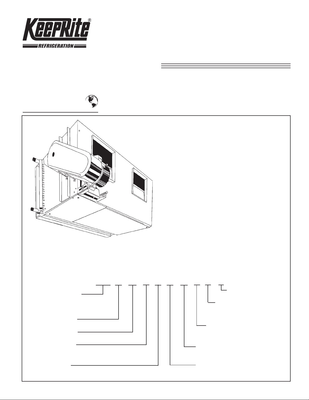
NOMENCLATURE
KHF 2 17 H A C H L P -
MODEL
KHF = FAN SELECTION ONL Y
KHD = FAN & HEAT COIL SECTION
KLS = FAN & COOLING COIL SECTION
NUMBER OF FANS (1 OR 2)
NOMINAL COIL FACE AREA
AIR FLOW ARRANGEMENT
H = HORIZONTAL AIR INT AKE/AIR FLOW
V = HORIZONTAL AIR INT AKE/VER TICAL AIRFLOW
FAN SECTION OPTIONS
A OR B
MANUFACTURING OPTIONS
MIX BOX AND ACCESS SECTION
OPTIONS
M, N, P OR Q
FACE AND BYP ASS SECTION OPTIONS
J, K OR L
FILTER SECTION OPTIONS
F , G OR H
COIL SECTION OPTIONS
C, D, OR E
Page 2
BLOWER COMPONENTS
FEATURES A NEW ADVANCED DYNAMIC DESIGN
BLOWER SECTION
• HIGH EFFICIENCY FAN PERFORMANCE
• FANS TESTED PER AMCA CODE No. 210
• MINIMUM FAN TIP SPEEDS
• SOLID STEEL SHAFTS
• MAXIMUM BEARING LIFE
The KeepPite air handler blower section is a matched
assembly combining advanced engineering techniques
with the finest materials available.
Large diameter forward-curved centrifugal fans were
designed specifically to operate at low tip-speeds with
minimum power consumption. Fan ratings are based on
tests conducted in accordance with AMCA test code
210. To meet the low noise level requirements of comfort
air conditioning, fan outlet velocities have been reduced
without sacrificing good fan performance. Both wheels
and housings are fabricated of continuous galvanized steel
to insure long troublefree service. Each fan wheel is
individually balanced electronically, and the entire fan
section is rechecked for dynamic balance after unit
assembly.
The fan section is complete with a rugged drive assembly.
The heavy duty motor base is designed for quick and
simple belt adjustment. Each drive combination is
selected for 210% overload based on motor horsepower.
All drives are furnished with matched V-belts. All variable
drive combinations are selected with a total adjustment
range of approximately 20%. The fan shaft is cone-drilled
for tachometer reading through an opening in the belt
guard.
For maximum durability, the entire cabinet assembly is
fabricated of continuous galvanized steel. This heavy
protective finish is maintained intact, completely
undisturbed and is complimented with the use of
corrosion resistant permanent fasteners. The positive
fastening principle of a permanent fastener provides the
rigidity and stability necessary for lifetime performance.
These exclusive KeepRite construction features offer
you the ultimate in air handling design.
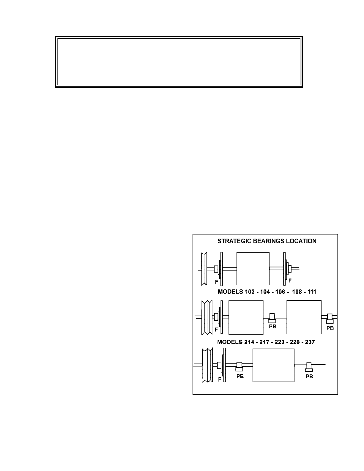
SOLID STEEL SHAFT WITH LIFETIME BEARINGS
All shafts are of uniform diameter, ground and polished
solid steel. Shaft sizes are selected to perform well
below first critical speed. Trouble free service with
minimum noise level is the quality specification for the
bearings on the KeepRite air handlers. Flanged and
pillow block type, are located for proper balance and
vibration free operation. Bearings are self aligning ball
type. Extended lubrication lines are standard.
EXCLUSIVE STEEL FRAME CONSTRUCTION
Sectionalized construction provides complete flexibflity of
unit arrangements with each individual section structurally
designed to provide the absolute maximum in unit
strength and rigidity.
All air handling units feature the extremely rugged Steel
Frame assembly. All static and dynamic forces are
directly transmitted to the unit framework. The bearings
are supported entirely by rigid frame members, eliminating
all dynamic forces from the casing panel. This design
removes all possibility of increased unit vibration caused
by panel mounted bearings.
FACE AND BY-PASS DAMPERS,
( MODELS 214 THRU 164)
The damper section and blades are fabricated of
continuous galvanized steel with the damper rods rotating
MODELS 141 - 150 - 164
in frictionless nylon bushings. Damper shaft extensions
are supplied on both ends to facilitate damper motor
location.
- 2 -
Page 3
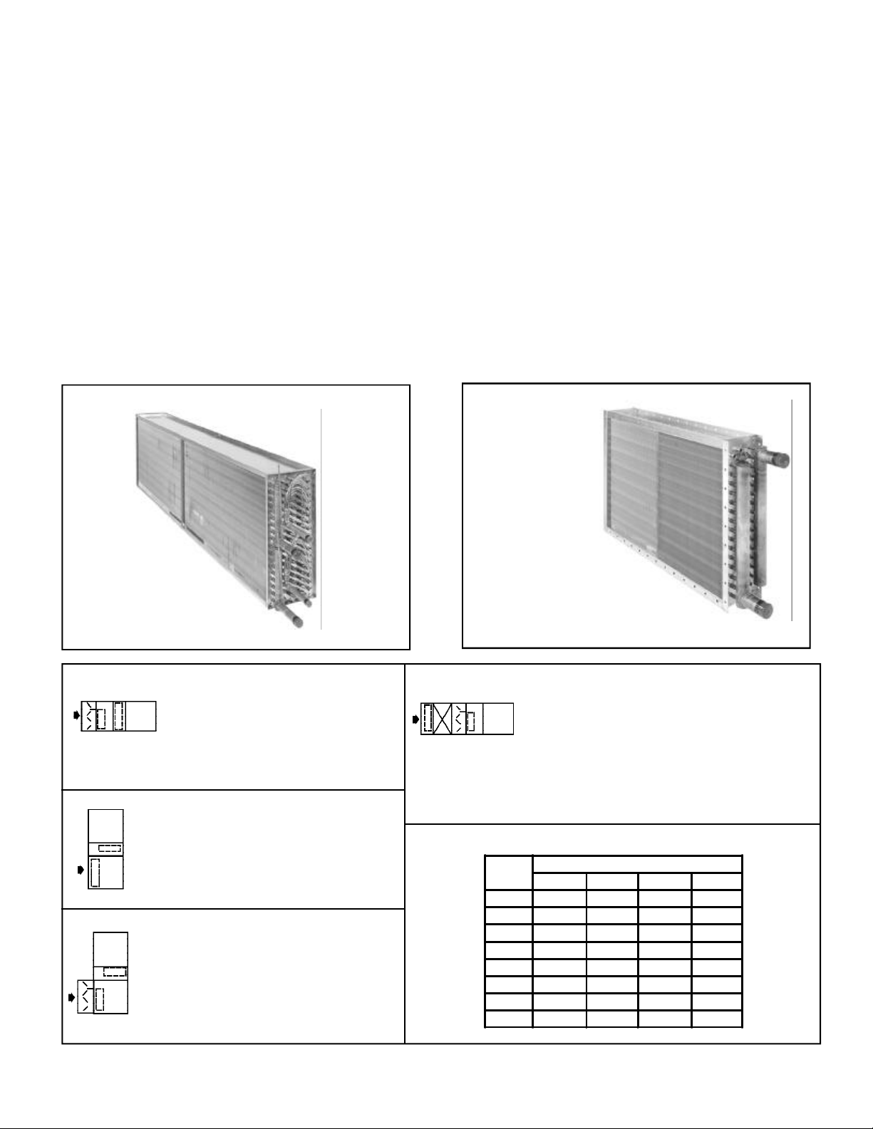
COIL INFORMATION
With the variety of coil sizes and types available for
mounting in factory fabricated units it is important to
follow a few general guidelines. Besides coil section
space and unit arrangement configuration limitations,
outlined below, care should be taken that all coils
mounted in the same section have identical face
dimensions. All coils by-passed with internal face and
by-pass damper sections must be of small face area.
The maximum coil space available in standard coil
sections is as follows:
Draw Thru-Horizontal or
Vertical Cooling Coil Section..........................= 17 7/8"
Blow Thru Cooling Coil Section.......................= 12 3/8"
Blow Thru Heating Coil Section.......................= 6 3/4"
Heating Coil Section - 1 Through 4 Row...........= 6 3/4"
The table below lists the depth dimension of the various
types and rows of coils. All dimensions are overall casing
depth. In order for the coils selected on a specific unit to
fit in a standard coil section, the sum of depth dimensions
of the coils in series must not exceed the maximum
space available.
Draw-Thru unit sizes 237 with medium or small face area
cooling coils and 141 with small face area cooling coils
are not equipped with the intermediate drain trough. For
this reason, the maximum space available with these
units may be increased by 2-3/4".
Selection of cooling & heating coils may be made from
current KeepRite Refrigeration catalogued data.
DIRECT EXPANSION
COIL (KDX)
Heating coil in reheat position with
internal by-pass of cooling coil only.
Cooling coil space consumed may not
exceed 9 5/8”. Heating coils need not
be same face area as cooling coil.
(Face and By-Pass Dampers not
available on models 103 thru 111).
Heating coil in reheat position.
Heating coil must be small face area
and cooling coil space consumed may
not exceed 9 5/8”.
Heating coil in reheat position with
internal face and by-pass of cooling coil
only. All coils must be small face area.
(Not available on Models 103 thru 111).
WATER HEATING &
COOLING COILS
(KWS, KWD, KWH)
Heating coil in preheat position with
internal by-pass of cooling coil.
Cooling coil must be small face area.
Heating coil may be large, medium or small
face area. For proper air distribution space is
required between the heating coil and the internal face
and by-pass damper section. An access section may be
used for this purpose. (Face and by-pass Dampers not
available on Models 103 thru 111).
COIL CASING DEPTH DIMENSIONS (INCHES)
ROWS
10 15-1/8 15-1/8 - 15-1/8
KWS KWH KWD KDX
1 4-1/8 4-1/8 - -
2 4-1/8 4-1/8 4-1/8 -
3 5-1/2 5-1/2 - 5-1/2
4 6-3/4 6-3/4 6-3/4 6-3/4
5 8-1/4 8-1/4 - 8-1/4
9-5/8 9-5/8 9-5/8 9-5/8
6
8 12-3/8 12-3/8 12-3/8 12-3/8
COIL TYPE
- 3 -
Page 4

UNIT SELECTION DATA
GENERAL - Certain basic factors must be predetermined
prior to the selection of a central station air handler. The
factors which will control the unit selection are applicable
codes, ventilation requirements. heating and cooling
space loads, acceptable temperature differentials, thermal
media and installation limitations. The selection of the
unit can then be resolved to five steps: (1) Unit type and
size, (2) Cooling coil, (3) Heating coil, (4) Accessories
and, (5) Motor size.
SELECTION OF UNIT TYPE AND SIZE - With the overall
system designed to minimize the number of units and the
heating, cooling and ventilation requirements for the
various zones established, selection of the optimum unit
size can be made based on the required air volume. The
heating load, cooling load and ventilation requirement will
establish a cfm need, any one of which may be the
maximum.
The unit air volume for cooling is dependent upon the
sensible space cooling load and the design dry bulb
temperature differential. Normal temperature differentials
for air conditioning are from 12 to 25 degrees °F. The
minimum air volume is calculated using the following
formula:
Normal temperaturedifferentials for heating are from 20 to
50 degrees °F. The required minimum air volume for
heating calculated using the same formula.
The required air volume for ventilation is generally less
than that for cooling or heating. However, where toxic
fumes or unusual contaminants are encountered, the
ventilation requirements may establish a minimum air
volume in excess of that determined for cooling or heating.
The unit size can then be selected based on maximum air
volume required. Usually more than one unit size can be
selected to deliver the required air. Therefore, fan outlet
velocity, coil face velocity, fan rpm and bhp should also be
given consideration in the final selection. The fan
performance tables are conveniently arranged with cfm,
fan outlet velocity, coil face velocity, fan rpm and bhp in
tabular form for simple selection of the optimum unit size.
(For Fan Performance Curves see Product Data sheet
AC4.7-PDS2).
SELECTION OF COILS - Having determined the unit size,
the selection of the coil is resolved to three steps:
(1) Choice of the face area coil for optimum face
(2) Choice of the type of coil suited to the application,
(3) Determination of number of rows and fin series.
Cfm =
velocity,
and
Sensible Space Load (Btuh)
1.09 x Temp. Differential
COOLING COIL - The coil size should be selected for
maximum face velocity to obtain peak heat transfer
efficiency and minimum cost. Generally 500 to 600 fpm
is considered the optimum coil face velocity range for
dehumidification application.
Determination of the number of rows and fin spacing is
made using the current KeepRite cooling coil
catalogues.
HEATING COIL - Selection of the heating coil is a
choice of coil type, size and determination of the
required number of rows and fin spacing.
Determination of the number of rows and fin spacing is
made from the current KeepRite Heating Coil
Catalogues.
SELECTION OF ACCESSORIES - Accessories should
be selected to provide a complete air conditioner with
proper cleaning, mixing and control of the air. KeepRite
offers a complete line of accessories to simplify the
selection and installation of accessories.
AIR CLEANING - A filter section should be selected to
provide filter area such that the filter velocity will be
compatible with the choice of filter media. KeepRite
offers two filter sections; flat, and angular, for units 214
thru 164. Units 103 thru 111 use flat only.
AIR MIXING - Mixing dampers are included as a simple
means of introducing outside air with thorough mixing
and proportional control of the recirculated and fresh air.
A mixing box is available for each unit size and is also
offered in combination with the angular filter section.
TEMPERATURE CONTROL - Dampers are often
selected as an effective means of temperature control
because they offer close control without time lag. Face
and by-pass dampers are available for units 214 thru
164. The face and by-pass dampers are available with
an internal by-pass duct (used with small face area coils
only) or with an external by-pass duct.
SELECTION OF FAN MOTOR - The determination of
the actual fan performance requires an accurate
calculation of the resistance to air flow thru the entire
system. This total resistance consists of two parts. the
external static pressure of the distribution system, and
the internal unit resistance.
The internal unit resistance is found by summing the
resistances of the coils, various unit components and
accessories. Components resistances are tabulated in
Table 2.
- 4 -
Page 5
FAN PERFORMANCE
DETERMINATION OF FAN SPEED AND MOTOR HP
REQUIREMENTS
Final determination of the actual fan performance
requires an accurate calculation of the total resistance
to air flow through the entire system. This total static
pressure (TSP) will consist of two parts: (1 ) the external
resistance due to air flow through the ducts, discharge
grilles, diffusers, etc. of the distribution system, and (2)
the internal resistance of the unit which results from air
flow through the coils, filters, unit cabinet and other
accessories. The method of calculating the resistance
for the various components of the distribution system
are well established. The internal resistances are easily
determined from Table 2 which tabulates the resistance
values for the various unit components in increments of
air volume. To the internal resistances as shown in
Table 2, the resistances of the cooling and heating coils
must be added. These may be obtained from the
KeepRite cooling and heating coil catalogues.
After calculating the total static pressure, the fan speed
and motor horsepower requirements can be accurately
determined. With the unit model, cfm and TSP known,
the fan rpm and bhp is easily determined from the Fan
Performance Tables.
FAN PERFORMANCE INFORMATION
This catalogue contains all of the fan performance tables
for the KeepRite central station air handlers. (For Fan
Performance Curves See Product Data Sheet AC4.7PDS2).
Low pressure Air Conditioners and low pressure Heating
and Ventilating units are equipped with forwardly curved
fan wheels as standard.
Further pressure loss correction is required for vertical
draw-thru KeepRite central station air conditioners, by
adding the casing air pressure drop found in Table 2,
”Component Air Friction”.
SELECTION RULES - The fan performance calculation
procedure is predicated on the fact that a fan is a
constant volume machine, provided the rpm and static
pressure do not change. This means the delivered air
volume (CFM) will not change, even though the
temperature may. The bhp required is inversely
proportional to final air temperature and altitude;
consequently bhp decreases with an increase in final air
temperature or higher altitude and increases with a
decrease in final air temperature or lower altitude. This
requires that the static pressure be adjusted for any air
conditions other than standard. After the calculation of
rpm and bhp, only the bhp need be corrected to the
specified conditions.
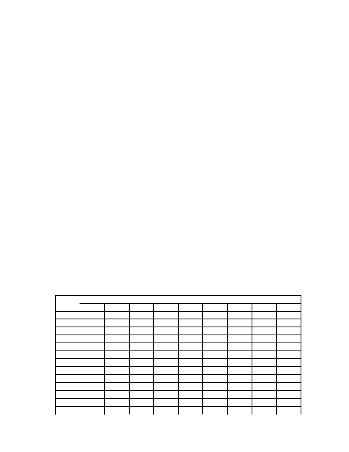
SELECTION PROCEDURE - The following data is required
to determine the fan performance. The unit type, unit
size, CFM, total static pressure, operating temperature
and altitude.
1. From Table 1, obtain the temperature and altitude
conversion factor.
2. Divide the specified total static pressure by the
conversion factor to obtain a corrected total static
pressure.
3. At the specified CFM and corrected total static
pressure, determine the rpm and bhp.
4. Multiply the bhp by the conversion factor to obtain
the bhp required at the specified attitude and
temperature.
TABLE NO. 1
AIR
TEMP. °F
-20 1.20 1.16 1.12 1.08 1.04 1.00 .97 .93 .89
0 1.15 1.10 1.08 1.02 .99 .95 .92 .88 .85
20 1.11 1.06 1.02 .98 .95 .92 .88 .85 .82
40 1.06 1.02 .98 .94 .91 .88 .84 .81 .78
60 1.02 .98 .94 .91 .88 .85 .81 .79 .76
70
80 .98 .94 .91 .88 .84 .81 .78 .75 .72
100 .94 .91 .88 .84 .81 .78 .75 .72 .70
120 .92 .88 .85 .81 .78 .76 .72 .70 .67
140 .89 .85 .82 .79 .76 .73 .70 .68 .65
160 .85 .82 .79 .76 .74 .70 .68 .65 .63
200 .80 .77 .75 .72 .69 .67 .64 .62 .60
250
TEMPERATURE AND ALTITUDE CONVERSION FACTORS
ALTITUDE (FEET)
0 1000 2000 3000 4000 5000 6000 7000 8000
1.00 .96 .93 .89 .86 .83 .80 .77 .74
.75 .72 .69 .67 .65 .62 .60 .58 .56
- 5 -
Page 6

TABLE 2
LOW PRESSURE DRAW THRU FC FAN WHEEL
UNIT
SIZE
103
OUTLET AREA
.84 SQ. FT.
COIL FACE AREA
LFA 2.3 SQ. FT.
104
OUTLET AREA
1.14 SQ. FT.
COIL FACE AREA
LFA 3.5 SQ. FT.
106
OUTLET AREA
1.88 SQ. FT.
COIL FACE AREA
LFA 5.5 SQ. FT.
108
OUTLET AREA
2.82 SQ. FT.
COIL FACE AREA
LFA 7.4 SQ. FT.
CFM
STD
AIR
700
800
900
1000
1100
1200
1300
1400
1600
1800
2000
1000
1200
1400
1600
1800
2000
2200
2400
2600
2800
3000
1750
2000
2250
2500
2750
3000
3250
3500
4000
4500
5000
2200
2600
3000
3400
3800
4200
4600
5000
5400
6200
7000
FAN
OUTLET
VEL
FPM
875
1000
1125
1250
1375
1500
1625
1750
2000
2250
2500
909
1090
1272
1454
1636
1818
2000
2181
2263
2545
2727
921
1052
1184
1315
1447
1578
1710
1842
2105
2368
2631
785
928
1071
1214
1357
1500
1642
1785
1928
2214
2500
COIL FACE VEL
FPM
LFA MFA SFA RPM BHP RPM BHP RPM BHP RPM BHP RPM BHP
318
363
409
454
500
545
590
636
727
818
909
294
352
411
470
529
588
647
705
764
823
882
318
363
409
454
500
545
590
636
727
818
909
297
351
405
459
513
567
621
675
729
837
945
N.A. N.A.
N.A. N.A.
N.A. N.A.
N.A. N.A.
580
595
614
636
660
685
713
741
803
870
940
411
424
443
467
494
524
555
588
621
655
690
438
466
498
533
569
607
646
686
766
849
932
341
359
382
408
438
469
502
535
570
640
712
TOTAL STATIC PRESSURE - INCHES OF WATER
0.25 0.50 0.75 1.00 1.25
0.05
0.07
0.08
0.10
0.12
0.15
0.18
0.22
0.31
0.42
0.57
0.07
0.09
0.13
0.18
0.24
0.31
0.40
0.50
0.62
0.76
0.92
0.15
0.20
0.26
0.33
0.42
0.52
0.64
0.78
1.12
1.55
2.08
0.17
0.23
0.30
0.39
0.51
0.65
0.82
1.02
1.25
1.82
2.55
809
808
812
822
836
854
874
896
944
997
1055
572
573
581
593
609
629
653
679
707
737
768
576
585
601
623
650
680
713
748
822
899
978
463
469
479
494
514
537
563
591
621
685
751
0.10
0.11
0.13
0.15
0.18
0.21
0.24
0.28
0.37
0.49
0.63
0.12
0.15
0.19
0.24
0.30
0.37
0.46
0.57
0.70
0.85
1.02
0.25
0.30
0.36
0.44
0.53
0.64
0.77
0.91
1.27
1.72
2.27
0.30
0.37
0.46
0.56
0.68
0.83
1.01
1.22
1.46
2.05
2.80
998
992
989
989
995
1004
1017
1033
1072
1117
1167
710
701
700
706
716
729
746
765
788
813
840
698
702
709
719
735
756
782
812
877
948
1022
566
567
571
579
591
607
627
649
675
730
791
0.15
0.17
0.19
0.21
0.24
0.27
0.31
0.35
0.45
0.57
0.72
0.19
0.22
0.27
0.32
0.38
0.45
0.55
0.66
0.78
0.94
1.11
0.35
0.41
0.48
0.56
0.66
0.77
0.90
1.05
1.42
1.89
2.46
0.44
0.53
0.63
0.75
0.88
1.04
1.23
1.45
1.70
2.30
3.08
1161
1154
1148
1143
1142
1144
1151
1161
1190
1228
1272
832
816
809
809
814
822
834
849
867
887
910
801
805
809
815
824
837
855
877
932
996
1066
654
653
654
658
665
676
690
708
728
777
832
0.21
0.23
0.25
0.28
0.31
0.34
0.38
0.43
0.53
0.66
0.81
0.28
0.31
0.35
0.40
0.47
0.55
0.64
0.75
0.88
1.03
1.21
0.46
0.53
0.61
0.71
0.81
0.92
1.05
1.21
1.59
2.06
2.65
0.59
0.70
0.81
0.95
1.10
1.27
1.47
1.69
1.95
2.58
3.37
1308
1297
1289
1283
1279
1277
1278
1283
1302
1332
1371
942
923
910
904
904
909
917
929
943
959
978
894
896
900
905
910
918
930
946
989
1045
1110
732
731
731
732
736
743
753
766
783
823
873
0.27
0.30
0.32
0.35
0.39
0.42
0.46
0.51
0.62
0.75
0.91
0.36
0.40
0.44
0.50
0.57
0.65
0.75
0.86
0.99
1.14
1.31
0.56
0.65
0.75
0.85
0.96
1.09
1.22
1.38
1.76
2.25
2.84
0.74
0.87
1.01
1.16
1.32
1.51
1.72
1.96
2.23
2.87
3.68
N.A. = Not Available LFA = Large Face Area MFA = Medium face Area SFA = Small face Area
- 6 -
Page 7
TABLE 2
LOW PRESSURE DRAW THRU FC FAN WHEEL
TOTAL STATIC PRESSURE - INCHES OF WATER
1.50 1.75 2.00 2.25 2.50 2.75 3.00
RPM BHP RPM BHP RPM BHP RPM BHP RPM BHP RPM BHP RPM BHP
****
1428
1419
1411
1405
1402
1399
1399
1410
1433
1465
1040
1022
1005
993
990
991
996
1005
1016
1029
1045
979
980
983
987
991
997
1004
1016
1049
1096
1154
804
802
800
800
802
807
814
824
837
871
914
*****
0.36
0.40
0.43
0.47
0.51
0.55
0.60
0.71
0.85
1.01
0.46
0.50
0.55
0.60
0.67
0.76
0.86
0.98
1.11
1.26
1.43
0.67
0.77
0.88
1.00
1.13
1.26
1.41
1.57
1.95
2.44
3.04
0.89
1.04
1.20
1.37
1.56
1.76
1.98
2.23
2.52
3.18
4.01
****
1551
1539
1530
1523
1518
1514
1511
1515
1529
1555
****
1112
1093
1079
1071
1069
1071
1077
1085
1096
1110
1059
1058
1060
1062
1066
1072
1077
1085
1110
1148
1199
870
867
865
864
865
868
872
880
890
918
956
*****
0.43
0.47
0.51
0.55
0.59
0.64
0.69
0.81
0.95
1.12
*****
0.61
0.66
0.71
0.79
0.88
0.98
1.10
1.23
1.39
1.56
0.79
0.90
1.02
1.15
1.29
1.44
1.59
1.76
2.16
2.65
3.26
1.05
1.22
1.40
1.59
1.80
2.02
2.26
2.52
2.81
3.50
4.35
****
****
1653
1641
1633
1626
1622
1618
1616
1625
1644
****
1197
1178
1161
1149
1144
1143
1146
1152
1162
1173
1134
1131
1131
1134
1137
1141
1146
1153
1171
1202
1246
932
929
925
924
925
925
929
934
942
965
998
*****
*****
0.55
0.59
0.64
0.68
0.73
0.79
0.91
1.05
1.23
*****
0.72
0.77
0.83
0.91
1.00
1.10
1.23
1.37
1.53
1.70
0.91
1.03
1.16
1.30
1.45
1.62
1.79
1.97
2.37
2.87
3.48
1.22
1.41
1.60
1.81
2.04
2.28
2.54
2.82
3.12
3.84
4.70
****
****
1760
1747
1737
1731
1723
1719
1713
1717
1731
****
****
****
****
****
1216
1213
1213
****
****
****
1204
1200
1200
1201
1203
1208
1211
1217
1231
1255
1294
991
986
983
981
980
980
982
987
992
1011
1040
*****
*****
0.63
0.68
0.73
0.78
0.83
0.89
1.01
1.16
1.34
*****
*****
*****
*****
*****
1.13
1.24
1.36
*****
*****
*****
1.03
1.16
1.30
1.45
1.62
1.80
1.98
2.17
2.60
3.10
3.72
1.39
1.59
1.81
2.04
2.28
2.54
2.82
3.12
3.44
4.18
5.07
****
****
****
****
****
****
****
****
****
****
****
****
****
****
****
****
****
****
****
****
****
****
1272
1266
1264
1264
1267
1271
1275
1279
1291
1310
1341
1046
1041
1037
1034
1034
1033
1035
1037
1042
1057
1081
*****
*****
*****
*****
*****
*****
*****
*****
*****
*****
*****
*****
*****
*****
*****
*****
*****
*****
*****
*****
*****
*****
1.15
1.29
1.44
1.61
1.78
1.98
2.18
2.38
2.83
3.35
3.97
1.56
1.78
2.02
2.27
2.54
2.81
3.11
3.43
3.77
4.53
5.44
****
****
****
****
****
****
****
****
****
****
****
****
****
****
****
****
****
****
****
****
****
****
1336
1330
1327
1326
1327
1330
1334
1339
1349
1364
1390
1099
1093
1089
1086
1084
1083
1084
1086
1089
1101
1122
*****
*****
*****
*****
*****
*****
*****
*****
*****
*****
*****
*****
*****
*****
*****
*****
*****
*****
*****
*****
*****
*****
1.28
1.43
1.59
1.76
1.95
2.16
2.37
2.59
3.07
3.60
4.23
1.74
1.98
2.23
2.50
2.79
3.08
3.40
3.73
4.09
4.89
5.83
****
****
****
****
****
****
****
****
****
****
****
****
****
****
****
****
****
****
****
****
****
****
1398
1391
1386
1385
1386
1388
1391
1396
1405
1418
1439
1149
1143
1139
1135
1133
1132
1132
1133
1136
1145
1163
*****
*****
*****
*****
*****
*****
*****
*****
*****
*****
*****
*****
*****
*****
*****
*****
*****
*****
*****
*****
*****
*****
1.42
1.57
1.74
1.92
2.12
2.34
2.56
2.80
3.31
3.86
4.50
1.92
2.17
2.45
2.74
3.04
3.36
3.70
4.05
4.43
5.25
6.22
CFM
STD
AIR
700
800
900
1000
1100
1200
1300
1400
1600
1800
2000
1000
1200
1400
1600
1800
2000
2200
2400
2600
2800
3000
1750
2000
2250
2500
2750
3000
3250
3500
4000
4500
5000
2200
2600
3000
3400
3800
4200
4600
5000
5400
6200
7000
OUTLET AREA
COIL FACE AREA
LFA 2.3 SQ. FT.
OUTLET AREA
1.14 SQ. FT.
COIL FACE AREA
LFA 3.5 SQ. FT.
OUTLET AREA
1.88 SQ. FT.
COIL FACE AREA
LFA 5.5 SQ. FT.
OUTLET AREA
2.82 SQ. FT.
COIL FACE AREA
LFA 7.4 SQ. FT.
UNIT
SIZE
103
.84 SQ. FT.
104
106
108
N.A. = Not Available LFA = Large Face Area MFA = Medium face Area SFA = Small face Area
- 7 -
Page 8
TABLE 3
LOW PRESSURE DRAW THRU FC FAN WHEEL
UNIT
SIZE
111
OUTLET AREA
3.45 SQ. FT.
COIL FACE AREA
LFA 10.6 SQ. FT.
214
OUTLET AREA
4.65 SQ. FT.
COIL FACE AREA
LFA 13.7 SQ. FT.
MFA 12.3 SQ. FT.
SFA 10.9 SQ. FT.
217
OUTLET AREA
5.63 SQ. FT.
COIL FACE AREA
LFA 16.8 SQ. FT.
MFA 15.1 SQ. FT.
SFA 13.4 SQ. FT.
222
OUTLET AREA
6.90 SQ. FT.
COIL FACE AREA
LFA 21.2 SQ. FT.
MFA 19.4 SQ. FT.
SFA 15.9 SQ. FT.
228
OUTLET AREA
10.26 SQ. FT.
COIL FACE AREA
LFA 26.9 SQ. FT.
MFA 24.7 SQ. FT.
SFA 20.2 SQ. FT.
CFM
STD
AIR
3000
3500
4000
4500
5000
5500
6000
7000
8000
9000
10000
4000
4500
5000
6000
7000
8000
9000
10000
11000
12000
13000
5000
6000
7000
8000
9000
10000
11000
12000
13000
14000
15000
6000
7000
8000
9000
10000
11000
12000
13000
15000
17000
19000
8000
9000
10000
11000
13000
15000
17000
19000
21000
23000
25000
FAN
OUTLET
VEL
FPM
857
1000
1142
1285
1428
1571
1714
2000
2285
2571
2857
851
957
1063
1276
1489
1702
1914
2127
2340
2553
2765
892
1071
1250
1428
1607
1785
1964
2142
2321
2500
2678
869
1014
1159
1304
1449
1594
1739
1884
2173
2463
2753
776
873
970
1067
1262
1456
1650
1844
2038
2233
2427
COIL FACE VEL
FPM
LFA MFA SFA RPM BHP RPM BHP RPM BHP RPM BHP RPM BHP
285
333
380
428
476
523
NA NA
571
666
761
857
952
294
325
366
406
488
569
650
732
813
894
976
1057
331
397
464
530
596
662
728
795
861
927
993
314
366
419
471
523
576
628
681
785
890
995
324
364
405
445
526
607
688
769
850
931
1012
366
412
458
550
642
733
825
917
***
***
***
373
447
522
597
671
746
820
895
970
***
***
379
443
506
569
632
696
759
822
949
***
***
398
447
497
547
646
746
845
945
***
***
***
330
367
441
514
588
661
735
808
882
955
297
357
416
476
535
595
654
714
773
833
892
283
330
377
424
471
518
566
613
707
801
896
297
334
371
408
483
557
631
706
780
855
929
0.25 0.50 0.75 1.00 1.25
320
339
363
391
422
454
487
554
624
695
766
410
428
450
497
550
605
662
720
779
839
900
369
397
432
469
509
550
591
634
677
721
765
334
355
380
407
436
466
496
528
592
657
724
269
280
293
308
339
373
407
443
480
517
555
TOTAL STATIC PRESSURE - INCHES OF WATER
0.25
0.34
0.45
0.59
0.77
0.99
1.24
1.90
2.76
3.86
5.22
0.35
0.44
0.55
0.84
1.22
1.71
2.33
3.09
4.01
5.10
6.38
0.43
0.63
0.90
1.24
1.66
2.18
2.81
3.54
4.41
5.40
6.54
0.52
0.70
0.94
1.24
1.61
2.05
2.57
3.17
4.67
6.60
9.01
0.69
0.86
1.07
1.31
1.93
2.73
3.75
5.00
6.51
8.32
10.45
430
437
447
462
482
506
533
592
656
723
791
538
547
560
592
633
679
730
783
838
894
951
485
499
520
547
579
614
652
691
731
772
813
440
450
464
483
504
529
555
583
642
703
766
356
361
368
377
400
427
458
490
524
558
593
0.43
0.54
0.65
0.80
0.98
1.19
1.46
2.12
3.01
4.13
5.52
0.56
0.66
0.78
1.10
1.52
2.06
2.73
3.54
4.51
5.65
6.98
0.70
0.92
1.21
1.57
2.03
2.59
3.26
4.05
4.96
6.01
7.20
0.84
1.05
1.31
1.64
2.03
2.50
3.05
3.70
5.27
7.29
9.80
1.14
1.35
1.58
1.86
2.54
3.43
4.55
5.91
7.54
9.47
11.72
520
525
530
539
550
565
585
634
691
752
817
647
653
660
682
713
751
794
842
893
946
1000
584
592
605
623
648
676
709
744
780
819
858
530
536
544
556
572
591
612
636
689
746
805
431
434
437
442
457
478
504
533
563
596
629
0.61
0.74
0.89
1.06
1.24
1.46
1.72
2.39
3.28
4.42
5.83
0.80
0.92
1.06
1.39
1.84
2.41
3.12
3.98
4.99
6.18
7.57
1.00
1.25
1.56
1.95
2.44
3.02
3.72
4.54
5.50
6.59
7.83
1.19
1.44
1.74
2.09
2.51
3.00
3.58
4.25
5.89
7.98
10.56
1.63
1.88
2.16
2.47
3.21
4.15
5.34
6.79
8.52
10.56
12.92
596
601
605
611
618
628
641
678
727
783
844
744
747
751
766
789
820
857
900
946
995
1047
671
676
685
697
715
738
765
795
828
864
901
610
613
618
626
637
651
669
688
734
786
843
496
498
500
503
513
528
549
573
601
631
663
0.79
0.95
1.13
1.32
1.54
1.77
2.04
2.70
3.60
4.74
6.16
1.06
1.20
1.35
1.71
2.18
2.77
3.51
4.40
5.46
6.70
8.13
1.31
1.60
1.95
2.37
2.87
3.48
4.20
5.05
6.04
7.17
8.45
1.56
1.86
2.19
2.57
3.02
3.54
4.14
4.83
6.53
8.67
11.33
2.13
2.43
2.76
3.12
3.93
4.93
6.17
7.68
9.49
11.61
14.08
664
668
672
678
683
690
699
726
767
816
872
831
832
834
845
863
887
919
956
998
1044
1092
749
752
759
768
781
798
820
846
876
908
943
682
683
686
692
700
711
724
740
780
827
879
555
555
556
558
565
577
593
613
638
665
695
0.98
1.16
1.37
1.59
1.83
2.10
2.38
3.06
3.95
5.10
6.53
1.33
1.49
1.67
2.06
2.55
3.16
3.92
4.84
5.94
7.22
8.69
1.64
1.97
2.36
2.81
3.34
3.97
4.71
5.59
6.60
7.76
9.07
1.95
2.29
2.66
3.09
3.56
4.11
4.74
5.46
7.20
9.40
12.11
2.63
2.99
3.37
3.78
4.69
5.76
7.06
8.61
10.49
12.68
15.23
N.A. = Not Available LFA = Large Face Area MFA = Medium face Area SFA = Small face Area
- 8 -
Page 9
TABLE 3
LOW PRESSURE DRAW THRU FC FAN WHEEL
TOTAL STATIC PRESSURE - INCHES OF WATER
1.50 1.75 2.00 2.25 2.50 2.75 3.00
RPM BHP RPM BHP RPM BHP RPM BHP RPM BHP RPM BHP RPM BHP
727
729
733
738
743
749
755
776
808
851
902
911
910
912
919
932
953
979
1012
1049
1091
1136
820
822
826
833
844
857
875
897
923
952
984
747
747
749
753
759
767
778
791
825
867
915
609
608
608
609
614
623
636
653
674
699
726
1.16
1.37
1.61
1.86
2.13
2.42
2.74
3.46
4.35
5.49
6.92
1.61
1.80
1.99
2.43
2.94
3.58
4.35
5.30
6.42
7.73
9.25
1.98
2.35
2.78
3.27
3.84
4.49
5.26
6.15
7.18
8.36
9.70
2.35
2.73
3.15
3.61
4.13
4.71
5.37
6.11
7.91
10.15
12.92
3.15
3.56
3.99
4.45
5.46
6.63
7.98
9.60
11.53
13.78
16.40
785
786
789
793
798
804
809
825
850
887
932
985
984
983
988
998
1015
1038
1066
1100
1138
1180
886
886
889
895
903
914
929
948
970
996
1025
808
806
807
810
815
821
829
840
869
906
951
659
657
657
658
661
667
677
691
710
732
757
1.36
1.59
1.85
2.13
2.43
2.76
3.10
3.86
4.78
5.92
7.35
1.89
2.10
2.33
2.81
3.35
4.01
4.81
5.77
6.92
8.26
9.81
2.34
2.75
3.22
3.75
4.35
5.03
5.83
6.74
7.79
8.99
10.36
2.75
3.18
3.65
4.16
4.72
5.33
6.02
6.80
8.64
10.93
13.75
3.69
4.14
4.63
5.14
6.25
7.50
8.95
10.62
12.60
14.91
17.58
840
840
842
845
850
855
860
874
894
924
964
1056
1053
1051
1053
1062
1076
1095
1120
1150
1185
1224
948
947
949
954
960
970
982
998
1017
1040
1066
865
863
863
864
867
872
880
889
913
946
987
706
704
702
702
704
709
718
729
745
765
787
1.56
1.81
2.09
2.39
2.73
3.08
3.45
4.28
5.23
6.39
7.81
2.17
2.41
2.66
3.19
3.78
4.47
5.29
6.27
7.44
8.81
10.38
2.70
3.15
3.66
4.23
4.87
5.60
6.42
7.36
8.43
9.65
11.04
3.16
3.65
4.16
4.72
5.31
5.97
6.70
7.50
9.40
11.75
14.61
4.24
4.73
5.26
5.82
7.05
8.40
9.93
11.68
13.71
16.08
18.81
892
890
891
894
898
903
908
920
937
962
997
1122
1118
1116
1116
1122
1134
1150
1171
1199
1230
1267
1008
1005
1006
1009
1015
1022
1033
1046
1063
1083
1107
919
915
915
915
918
922
928
935
956
985
1023
750
747
746
745
746
750
757
766
780
797
818
1.76
2.04
2.34
2.66
3.02
3.40
3.81
4.70
5.70
6.88
8.30
2.46
2.73
3.01
3.59
4.22
4.94
5.78
6.78
7.98
9.36
10.96
3.08
3.57
4.12
4.73
5.41
6.17
7.03
7.99
9.09
10.33
11.74
3.59
4.11
4.68
5.28
5.93
6.62
7.39
8.23
10.19
12.58
15.50
4.80
5.33
5.92
6.52
7.85
9.31
10.94
12.77
14.87
17.28
20.08
942
939
939
941
945
950
955
965
980
1001
1031
1185
1180
1178
1176
1180
1189
1203
1223
1247
1276
1309
1063
1060
1059
1062
1067
1073
1082
1094
1109
1127
1147
969
966
964
965
966
969
974
980
998
1025
1058
792
789
787
786
786
788
794
802
814
829
848
1.97
2.27
2.59
2.94
3.32
3.73
4.17
5.12
6.17
7.38
8.82
2.77
3.05
3.36
3.99
4.66
5.43
6.29
7.33
8.53
9.93
11.56
3.47
4.00
4.59
5.24
5.97
6.76
7.65
8.64
9.77
11.04
12.47
4.01
4.59
5.20
5.85
6.54
7.29
8.09
8.97
10.99
13.45
16.40
5.38
5.96
6.58
7.24
8.67
10.23
11.96
13.87
16.04
18.53
21.37
989
986
985
986
989
993
998
1008
1022
1039
1066
1244
1239
1236
1233
1235
1243
1255
1272
1294
1320
1352
1116
1112
1110
1112
1117
1123
1130
1140
1153
1168
1188
1017
1014
1012
1011
1012
1015
1018
1025
1039
1062
1093
832
829
826
824
823
825
830
837
847
861
877
2.19
2.50
2.85
3.22
3.62
4.06
4.53
5.53
6.66
7.90
9.37
3.07
3.38
3.71
4.40
5.12
5.92
6.82
7.87
9.10
10.52
12.17
3.87
4.44
5.06
5.76
6.52
7.36
8.28
9.31
10.48
11.76
13.22
4.44
5.08
5.74
6.43
7.17
7.96
8.80
9.73
11.81
14.33
17.34
5.97
6.59
7.24
7.94
9.47
11.15
12.99
15.00
17.24
19.80
22.70
1035
1030
1028
1029
1031
1035
1040
1050
1061
1078
1100
1300
1296
1292
1288
1289
1295
1306
1321
1340
1365
1393
1168
1162
1160
1161
1164
1169
1176
1185
1197
1211
1228
1064
1061
1058
1057
1057
1059
1061
1067
1080
1100
1128
870
867
864
862
860
861
865
871
880
891
907
2.41
2.74
3.11
3.50
3.93
4.39
4.88
5.95
7.13
8.44
9.93
3.37
3.71
4.07
4.80
5.58
6.42
7.36
8.44
9.68
11.13
12.79
4.28
4.89
5.55
6.28
7.08
7.96
8.93
10.00
11.19
12.51
13.98
4.89
5.57
6.28
7.03
7.82
8.65
9.53
10.50
12.66
15.22
18.29
6.56
7.22
7.93
8.69
10.29
12.07
14.01
16.12
18.46
21.07
24.04
CFM
STD
AIR
3000
3500
4000
4500
5000
5500
6000
7000
8000
9000
10000
4000
4500
5000
6000
7000
8000
9000
10000
11000
12000
13000
5000
6000
7000
8000
9000
10000
11000
12000
13000
14000
15000
6000
7000
8000
9000
10000
11000
12000
13000
15000
17000
19000
8000
9000
10000
11000
13000
15000
17000
19000
21000
23000
25000
OUTLET AREA
COIL FACE AREA
LFA 10.6 SQ. FT.
OUTLET AREA
COIL FACE AREA
LFA 13.7 SQ. FT.
MFA 12.3 SQ. FT.
SFA 10.9 SQ. FT.
OUTLET AREA
COIL FACE AREA
LFA 16.8 SQ. FT.
MFA 15.1 SQ. FT.
SFA 13.4 SQ. FT.
OUTLET AREA
COIL FACE AREA
LFA 21.2 SQ. FT.
MFA 19.4 SQ. FT.
SFA 15.9 SQ. FT.
OUTLET AREA
COIL FACE AREA
LFA 26.9 SQ. FT.
MFA 24.7 SQ. FT.
SFA 20.2 SQ. FT.
UNIT
SIZE
111
3.45 SQ. FT.
214
4.65 SQ. FT.
217
5.63 SQ. FT.
222
6.90 SQ. FT.
228
10.26 SQ. FT.
N.A. = Not Available LFA = Large Face Area MFA = Medium face Area SFA = Small face Area
- 9 -
Page 10
TABLE 4
LOW PRESSURE DRAW THRU FC FAN WHEEL
UNIT
SIZE
237
OUTLET AREA
12.42 SQ. FT.
COIL FACE AREA
LFA 35.9 SQ. FT.
MFA 31.4 SQ. FT.
SFA 29.2 SQ. FT.
141
OUTLET AREA
13.79 SQ. FT.
COIL FACE AREA
LFA 40.4 SQ. FT.
MFA 38.0 SQ. FT.
SFA 31.4 SQ. FT.
150
OUTLET AREA
16.77 SQ. FT.
COIL FACE AREA
LFA 49.3 SQ. FT.
MFA 44.8 SQ. FT.
SFA 38.0 SQ. FT.
164
OUTLET AREA
20.48 SQ. FT.
COIL FACE AREA
LFA 62.8 SQ. FT.
MFA 53.8 SQ. FT.
SFA 49.3 SQ. FT.
CFM
STD
AIR
10000
12000
14000
16000
18000
20000
22000
24000
26000
28000
32000
12000
14000
16000
18000
20000
22000
24000
26000
28000
32000
15000
18000
21000
24000
27000
30000
33000
36000
18000
20000
24000
28000
32000
36000
40000
44000
48000
FAN
OUTLET
VEL
FPM
806
967
1129
1290
1451
1612
1774
1935
2096
2258
2580
869
1014
1159
1304
1449
1594
1739
1884
2028
2318
892
1071
1250
1428
1607
1785
1964
2142
878
975
1170
1365
1560
1756
1951
2146
2341
COIL FACE VEL
FPM
LFA MFA SFA RPM BHP RPM BHP RPM BHP RPM BHP RPM BHP
279
318
343
242
335
382
412
260
391
446
481
281
446
509
549
304
502
573
618
328
558
637
687
353
614
701
756
378
670
764
824
405
726
828
893
431
782
892
962
459
893
1019
297
347
397
446
496
545
595
645
694
794
304
365
425
486
547
608
669
730
287
318
382
446
510
574
637
701
765
334
390
446
501
557
612
668
724
780
891
335
402
469
536
603
670
737
804
335
372
446
520
595
669
743
818
892
***
382
445
509
573
636
700
764
828
891
***
393
472
551
629
708
787
866
944
365
405
486
567
649
730
811
892
973
514
172
183
195
208
221
235
249
264
279
310
155
167
180
194
210
226
243
260
141
147
160
174
189
204
220
237
253
TOTAL STATIC PRESSURE - INCHES OF WATER
0.25 0.50 0.75 1.00 1.25
0.86
1.22
1.70
2.31
3.09
4.03
5.17
6.52
8.10
9.93
14.40
1.11
1.52
2.03
2.65
3.39
4.27
5.30
6.50
7.88
11.23
1.35
1.97
2.77
3.80
5.08
6.64
8.53
10.77
1.65
2.04
3.01
4.26
5.88
7.90
10.38
13.38
16.95
320
329
342
358
378
399
422
446
470
496
547
222
229
238
249
260
272
285
298
311
339
201
209
219
230
242
256
270
285
182
185
195
207
220
233
247
262
277
1.39
1.83
2.38
3.06
3.90
4.91
6.12
7.55
9.21
11.11
15.75
1.70
2.18
2.79
3.52
4.38
5.39
6.54
7.86
9.36
12.95
2.10
2.83
3.75
4.91
6.32
8.02
10.04
12.40
2.54
3.01
4.18
5.65
7.48
9.69
12.35
15.51
19.25
386
391
399
410
425
443
462
484
506
530
578
265
270
276
284
294
305
316
328
340
366
240
246
253
262
273
284
296
310
217
219
226
235
247
259
272
285
299
1.98
2.49
3.11
3.87
4.78
5.86
7.13
8.63
10.35
12.33
17.12
2.38
2.91
3.57
4.38
5.33
6.44
7.70
9.15
10.77
14.61
2.93
3.75
4.78
6.04
7.58
9.41
11.56
14.06
3.52
4.05
5.35
7.01
9.04
11.48
14.35
17.72
21.63
443
447
452
460
471
485
501
520
540
562
608
304
307
311
317
325
334
355
344
367
391
275
279
284
292
301
311
322
334
249
250
254
262
271
282
294
307
320
2.59
3.18
3.88
4.71
5.69
6.84
8.19
9.75
11.54
13.58
18.52
3.12
3.71
4.41
5.27
6.29
7.48
8.85
10.39
12.12
16.21
3.84
4.74
5.86
7.23
8.87
10.82
13.10
15.73
4.61
5.18
6.58
8.38
10.59
13.23
16.33
19.92
24.05
495
497
501
507
515
526
539
555
573
593
636
339
341
344
348
354
362
371
381
391
414
307
309
313
319
327
336
346
356
278
278
281
286
294
304
315
327
339
3.23
3.91
4.68
5.60
6.65
7.88
9.29
10.92
12.77
14.90
19.95
3.91
4.56
5.33
6.23
7.30
8.55
9.98
11.62
13.46
17.76
4.82
5.79
7.00
8.47
10.20
12.26
14.66
17.41
5.78
6.40
7.90
9.80
12.16
14.97
18.28
22.08
26.43
N.A. = Not Available LFA = Large Face Area MFA = Medium face Area SFA = Small face Area
- 10 -
Page 11

TABLE 4
LOW PRESSURE DRAW THRU FC FAN WHEEL
TOTAL STATIC PRESSURE - INCHES OF WATER
1.50 1.75 2.00 2.25 2.50 2.75 3.00
RPM BHP RPM BHP RPM BHP RPM BHP RPM BHP RPM BHP RPM BHP
542
543
546
551
557
566
577
590
606
624
663
372
372
374
377
382
388
396
405
415
436
336
337
340
345
351
359
368
378
304
304
306
310
316
324
334
345
357
3.89
4.65
5.52
6.50
7.64
8.94
10.42
12.13
14.05
16.23
21.43
4.74
5.46
6.28
7.24
8.35
9.65
11.16
12.87
14.79
19.29
5.86
6.91
8.20
9.75
11.58
13.74
16.24
19.11
7.01
7.69
9.26
11.29
13.75
16.73
20.19
24.22
28.78
586
586
588
592
597
604
613
625
638
654
690
401
401
403
405
408
414
420
428
437
457
363
363
365
369
375
382
390
399
329
329
329
332
337
344
353
363
374
4.57
5.42
6.37
7.44
8.65
10.02
11.58
13.37
15.37
17.61
22.93
5.58
6.39
7.28
8.30
9.45
10.80
12.37
14.13
16.11
20.80
6.95
8.09
9.46
11.08
13.01
15.26
17.86
20.84
8.31
9.05
10.76
12.86
15.42
18.51
22.14
26.35
31.09
627
626
627
630
635
641
648
658
670
684
717
429
429
430
431
434
438
444
451
458
477
389
388
389
392
397
403
410
419
352
351
352
354
357
364
371
380
391
5.28
6.21
7.23
8.39
9.69
11.14
12.78
14.61
16.69
19.02
24.49
6.47
7.36
8.32
9.39
10.61
12.01
13.62
15.43
17.48
22.31
8.10
9.32
10.75
12.48
14.47
16.82
19.52
22.61
9.65
10.46
12.28
14.48
17.14
20.35
24.10
28.45
33.42
666
664
664
667
671
676
682
691
701
713
743
456
455
455
456
459
462
466
473
480
497
413
412
412
414
418
424
430
438
374
373
373
374
377
382
389
397
407
6.01
7.01
8.13
9.37
10.74
12.27
13.99
15.91
18.06
20.45
26.05
7.38
8.34
9.38
10.52
11.80
13.26
14.89
16.78
18.88
23.84
9.32
10.58
12.09
13.91
16.01
18.43
21.21
24.41
11.06
11.92
13.87
16.16
18.92
22.21
26.09
30.62
35.74
704
700
700
702
705
710
715
722
731
743
770
481
480
480
481
482
485
489
494
500
516
435
434
434
435
439
443
449
457
395
393
393
394
396
400
406
413
422
6.76
7.84
9.04
10.37
11.81
13.43
15.21
17.22
19.43
21.92
27.66
8.31
9.35
10.48
11.69
13.04
14.53
16.25
18.15
20.32
25.41
10.58
11.90
13.50
15.38
17.56
20.06
22.94
26.23
12.53
13.43
15.50
17.92
20.77
24.15
28.17
32.78
38.06
740
735
734
735
738
742
747
753
761
771
796
505
504
503
504
505
507
510
514
520
534
457
456
455
456
458
462
468
474
414
413
412
412
414
417
422
429
438
7.52
8.68
9.96
11.38
12.90
14.61
16.47
18.55
20.86
23.39
29.28
9.30
10.39
11.59
12.89
14.30
15.86
17.62
19.57
21.77
26.97
11.90
13.28
14.95
16.89
19.16
21.75
24.74
28.07
14.02
15.00
17.18
19.71
22.67
26.15
30.22
34.97
40.44
775
769
766
767
769
773
778
783
790
799
821
528
527
526
526
527
528
531
535
540
553
478
477
476
476
478
481
486
492
434
432
430
431
432
434
439
445
453
8.33
9.53
10.90
12.39
14.02
15.80
17.75
19.91
22.28
24.89
30.92
10.29
11.46
12.72
14.10
15.58
17.22
19.02
21.04
23.29
28.59
13.29
14.71
16.44
18.45
20.78
23.48
26.52
29.97
15.60
16.61
18.90
21.58
24.62
28.19
32.40
37.26
42.80
CFM
STD
AIR
10000
12000
14000
16000
18000
20000
22000
24000
26000
28000
32000
12000
14000
16000
18000
20000
22000
24000
26000
28000
32000
15000
18000
21000
24000
27000
30000
33000
36000
18000
20000
24000
28000
32000
36000
40000
44000
48000
UNIT
SIZE
237
OUTLET AREA
12.42 SQ. FT.
COIL FACE AREA
LFA 35.9 SQ. FT.
MFA 31.4 SQ. FT.
SFA 29.2 SQ. FT.
141
OUTLET AREA
13.79 SQ. FT.
COIL FACE AREA
LFA 40.4 SQ. FT.
MFA 38.0 SQ. FT.
SFA 31.4 SQ. FT.
150
OUTLET AREA
16.77 SQ. FT.
COIL FACE AREA
LFA 49.3 SQ. FT.
MFA 44.8 SQ. FT.
SFA 38.0 SQ. FT.
164
OUTLET AREA
20.48 SQ. FT.
COIL FACE AREA
LFA 62.8 SQ. FT.
MFA 53.8 SQ. FT.
SFA 49.3 SQ. FT.
N.A. = Not Available LFA = Large Face Area MFA = Medium face Area SFA = Small face Area
- 11 -
Page 12

TABLE 5
COMPONENT AIR FRICTION
(INCHES OF WATER)
UNIT
SIZE
103
104
106
108
111
214
217
FILTERS DAMPERS
CFM
800
1000
1200
1400
1600
1800
2000
1000
1200
1400
1800
2200
2600
3000
2000
2500
3000
3500
4000
4500
5000
2200
2600
3400
3800
4600
5400
7000
3000
3500
4000
5000
6000
8000
10000
4000
4500
5000
7000
9000
11000
13000
5000
6000
7000
9000
11000
13000
15000
FLAT ANGULAR
TA Clean Hi-Vel TA Clean Hi-Vel
0.04
0.04
0.04
0.06
0.06
0.05
0.09
0.08
0.06
0.12
0.11
0.07
0.15
0.13
0.08
0.19
0.16
0.11
-
0.21
0.13
0.04
0.04
0.04
0.05
0.05
0.05
0.07
0.07
0.06
0.12
0.11
0.08
0.18
0.15
0.09
-
0.19
0.13
-
-
0.19
0.07
0.07
0.05
0.11
0.10
0.06
0.15
0.13
0.08
0.21
0.17
0.11
-
0.21
0.15
-
-
0.19
-
-
0.23
0.06
0.06
0.04
0.08
0.08
0.05
0.14
0.12
0.08
0.17
0.14
0.10
-
0.18
0.12
-
-
0.19
-
-
-
0.06
0.06
0.05
0.08
0.08
0.05
0.11
0.10
0.06
0.16
0.14
0.09
-
0.19
0.13
-
-
0.19
-
-
-
0.07
0.07
0.05
0.09
0.08
0.06
0.11
0.10
0.06
0.21
0.17
0.11
-
-
0.19
-
-
-
-
-
-
0.07
0.07
0.06
0.11
0.10
0.06
0.14
0.12
0.08
-
0.19
0.13
-
-
0.19
-
-
-
-
-
-
N.A. N.A. N.A.
N.A. N.A. N.A.
N.A. N.A. N.A.
N.A. N.A. N.A.
N.A. N.A. N.A.
0.03
0.03
0.03
0.04
0.04
0.04
0.05
0.05
0.04
0.09
0.09
0.06
0.15
0.13
0.09
-
0.18
0.12
-
-
0.17
0.04
0.04
0.04
0.06
0.06
0.04
0.07
0.07
0.06
0.10
0.09
0.07
0.19
0.16
0.10
-
0.20
0.15
-
-
0.19
Mixing
Box
0.02
0.02
0.03
0.04
0.05
0.06
0.08
0.02
0.02
0.02
0.04
0.06
0.09
0.12
0.03
0.04
0.07
0.09
0.12
0.15
0.17
0.02
0.02
0.04
0.05
0.08
0.11
0.19
0.02
0.02
0.03
0.05
0.07
0.12
0.18
0.02
0.02
0.03
0.06
0.10
0.15
0.19
0.02
0.03
0.04
0.07
0.10
0.14
0.17
Face
& By
Pass
N.A.
N.A.
N.A.
N.A.
N.A.
0.02
0.03
0.04
0.07
0.11
0.16
0.22
0.03
0.04
0.05
0.08
0.11
0.15
0.20
Vert.
Unit
Casing
0.05
0.10
0.17
0.25
0.31
-
-
0.06
0.10
0.16
0.28
0.35
0.41
-
0.35
0.43
0.63
0.85
1.11
-
-
0.05
0.08
0.16
0.22
0.31
0.36
-
0.05
0.08
0.11
0.21
0.30
0.40
-
0.06
0.08
0.11
0.26
0.36
-
-
0.07
0.11
0.18
0.30
0.37
0.42
-
UNIT
SIZE
222
228
237
141
150
164
FILTERS DAMPERS
CFM
6000
7000
8000
10000
12000
15000
19000
8000
9000
10000
13000
17000
21000
25000
10000
12000
14000
18000
22000
26000
32000
12000
14000
16000
20000
24000
28000
36000
15000
18000
21000
27000
33000
39000
45000
18000
20000
24000
32000
40000
48000
56000
FLAT ANGULAR
TA Clean Hi-Vel TA Clean Hi-Vel
0.06
0.06
0.04
0.04
0.08
0.08
0.05
0.11
0.16
-
-
-
0.07
0.09
0.11
0.18
-
-
-
0.07
0.10
0.14
0.22
-
-
-
0.07
0.09
0.12
0.19
-
-
-
0.08
0.11
0.15
-
-
-
-
0.07
0.09
0.14
-
-
-
-
0.10
0.14
0.19
-
-
0.07
0.08
0.10
0.15
-
-
-
0.07
0.09
0.12
0.17
-
-
-
0.07
0.08
0.11
0.15
0.21
-
-
0.08
0.10
0.13
0.19
-
-
-
0.07
0.09
0.12
0.19
-
-
-
0.06
0.09
0.13
0.20
-
0.05
0.06
0.06
0.09
0.16
-
-
0.05
0.06
0.08
0.12
0.18
-
-
0.05
0.06
0.07
0.10
0.15
0.20
-
0.05
0.07
0.08
0.13
0.20
-
-
0.06
0.06
0.08
0.13
0.21
-
-
0.05
0.07
0.11
0.15
0.04
0.06
0.07
0.11
0.19
0.04
0.06
0.07
0.12
0.19
0.04
0.05
0.07
0.11
0.15
0.21
0.04
0.06
0.07
0.12
0.19
0.03
0.04
0.06
0.11
0.18
Mixing
Box
0.04
0.04
0.02
0.05
0.05
0.05
0.06
0.08
0.13
0.21
0.04
0.04
0.05
0.07
0.11
0.16
0.23
0.04
0.04
0.06
0.07
0.10
0.15
0.22
0.04
0.05
0.05
0.06
0.08
0.11
0.19
0.04
0.04
0.06
0.07
0.10
0.14
0.19
0.04
0.04
0.05
0.07
0.09
0.13
0.19
0.02
0.03
0.04
0.06
0.09
0.15
0.02
0.02
0.03
0.04
0.08
0.12
0.16
0.02
0.02
0.03
0.05
0.07
0.10
0.15
0.02
0.02
0.03
0.04
0.05
0.08
0.12
0.02
0.04
0.04
0.07
0.10
0.15
0.19
0.02
0.03
0.04
0.07
0.11
0.15
0.20
0.07
0.10
0.13
-
0.19
-
-
0.05
0.06
0.07
0.10
0.16
-
0.22
-
-
0.04
0.06
0.07
0.11
0.16
-
0.20
-
-
0.04
0.05
0.07
0.10
0.13
0.17
-
-
0.04
0.06
0.07
0.11
0.15
-
0.20
-
-
0.03
0.05
0.06
0.10
0.15
-
0.19
-
-
Face
& By
Pass
0.02
0.03
0.04
0.06
0.08
0.13
0.20
0.03
0.03
0.04
0.06
0.10
0.16
0.22
0.02
0.03
0.04
0.07
0.10
0.13
0.20
0.03
0.04
0.04
0.06
0.09
0.12
0.20
0.03
0.04
0.05
0.08
0.12
0.17
0.22
0.03
0.03
0.03
0.07
0.11
0.15
0.21
Vert.
Unit
Casing
0.04
0.05
0.08
0.14
0.24
0.33
N. A. - Not Available
Note: When using cooling and heating coils refer to current
catalogued data on these products for air friction
-
-
-
-
-
-
-
-
-
-
-
-
-
-
-
-
-
-
-
-
-
-
-
-
-
-
-
-
-
-
-
-
-
-
-
-
- 12 -
Page 13

SOUND LEVEL DATA
In addition to vibration transmission, sound generated
by the fan itself must be considered in properly
engineered systems. After the final selection of the
central station unit is made the engineer should analyze
the expected sound power spectrum and proceed
SOUND POWER LEVEL ESTIMATING
SOUND
with the necessary attenuation analysis, which may
include considerations of unit placement (away from
occupied areas), acoustical insulation in the equipment
room, duct silencers, or acoustical duct lining.
The following method of estimating centrifugal fan sound
power level spectrums is taken from the latest
ASHRAE, sources. The method does not take into
consideration such factors as cabinet attenuation or
inefficient unit selection, but does provide conservative
dB = (Base dB) + (System dB) + (Blade Passage Frequency dB) + (Multi-Fan dB)
The base dB is found in the table at the
right by entering the octave band and
reading the dB in the appropriate row.
TABLE adopted with permission
from the 1980 ASHRAE Handbook
and Product Directory (Systems)
approximate values upon which to base an acoustical
attenuation analysis.
Sound power levels in decibels re 10
-12
watts in each of
the eight octave bands may be estimated with the
following formula:
BASE dB
BASE DECIBEL TABLE
OCTAVE BAND NUMBER
1 2 3 4 5 6 7
OCTAVE BAND CENTER FREQUENCY Hz
63 125 250 500 1000 2000 4000
OCTAVE BAND FREQUENCY RANGE Hz
45-90 90-180 180-355 355-710 710-1400 1400-2800 2800-5600
BASE dB (FORWARD CURVED WHEEL), Hz
47 43 39 33 28 25 23
SYSTEM dB
The system dB is found in the chart at
the right by entering the chart at the
flow rate, rise vertically to the
pressure of the system and read the decibels.
CHART reprinted with permission
from the 1975 ASHRAE Handbook
and Product Directory (Equipment)
BLADE PASSAGE FREQUENCY dB
The Blade Passage Frequently dB is found:
1. For forward curved fan wheel units - add 2 dB to the
one octave band which contains the frequency equal
to the RPM of the fan.
CFM - PRESSURE CHART
20.
O
2
10.
5.0
3.0
2.0
1.0
PRESSURE INCHES H
0.5
100 500 1000 5000 10000 100000
50000 200000
MULTI-FAN dB
Multi-Fan dB:
1. For two fan wheel units - add three dB to each band.
- 13 -
Page 14

TABLE 6
PHYSICAL DATA
CFM RANGE
BY UNIT TYPE
KLS
KHF
FAN DATA
STANDARDF
KHD
LARGE
MEDIUM
COIL DATA
SMALL
FLAT
FILTER
SECTION
ANGULAR
FILTER
SECTION
FILTER DATA
COMBINATION
ANGULAR
FILTER SECTION
BLOWER
SECTION
DRAW THRU
COOLING
COIL SECT
METAL GAUGES
DESCRIPTION
KHF Vent, Unit Low Press. Draw Thru 700-2000 1000-3000 1750-5000 2200-7000
KHD Heat and Vent Unit 700-2000 1000-3000 1750-5000 2200-7000
KLS Low Press. Draw Thru 700-2000 1000-3000 1750-5000 2200-7000
Outlet Area - Square Feet
Number - Diameter (in) - Type
Shaft and Bearing Size (in)
Outlet Area - Square Feet
Number - Diameter (in) - Type
Shaft and Bearing Size (in)
Number - Size (in)
Face Area - Square Feet
Number - Size (in)
Face Area - Square Feet
Number - Size (in)
Face Area - Square Feet
Number - Size (in)
Filter Area - Square Feet
Number - Size (in)
Filter Area - Square Feet
Number - Size (in)
Filter Area - Square Feet
Structural Frame
Discharge Panel
Removable Panel
Structural Frame - All
Bottom Panel - All
Drain Pan - Horizontal
Drain Pan - Vertical
Removable Panels - All
103 104 106 108
0.84
1 -9 FC
1
0.84
1 -9 FC
1
1 - 15x21.5
2.3
N.A. N.A. N.A. N.A.
N.A. N.A. N.A. N.A.
2 - 16x20x2
4.4
N.A. N.A. N.A. N.A.
2 - 16x25x2
5.6
14 & 16
18
20
14 & 16
16
18
18
20
1 - 18x27.5
2 - 20x20x2
4 - 16x20x2
UNIT SIZE
1.14
1 - 12 FC
1
1.14
1 - 12 FC
1
3.5
5.6
8.9
14 & 16
18
20
14 & 16
16
18
18
20
1.88
1 - 12-1/4 FC
1-7/16
1.88
1 - 12-1/4 FC
17/16
1 - 21x37.5
5.5
3 - 16x25x2
8.4
6 - 16x20x2
13.3
14 & 16
18
20
14 & 16
16
18
18
20
2.82
1 - 15 FC
1-7/16
2.82
1 - 15 FC
17/16
1 - 30x35.5
7.4
2 - 16x20x2
2 - 16x25x2
10.0
6 - 16x25x2
16.7
14
16
20
14 & 16
16
18
16
20
N.A. = Not Available
FORWARD CURVED FAN WHEELS
TABLE 7
UNIT
SIZE
103 1 9 2 1
104 1 12 2 1
106 1 12 1/4 2 1 7/16
108 1 15 2 1 7/16
111 1 16 1/2 2 1 11/16
214 2 13 1/2 3 1 7/16
217 2 15 3 1 11/16
222 2 16 1/2 3 1 11/16
228 2 20 3 2 3/16
237 2 22 1/4 3 2 3/16
141 1 33 3 2 3/16
150 1 36 1/2 3 2 7/16
164 1 40 1/4 3 2 11/16
LOW PRESSURE UNITS
FAN WHEEL FAN BEARING
QTY. DIAMETER (IN) QTY. SIZE (IN)
- 14 -
Page 15

PHYSICAL DATA
TABLE 6
UNIT SIZE
111 214 217 222 228 237 141 150 164
3000-10000 4000-13000 5000-15000 6000-19000 8000-25000 10000-32000 12000-32000 15000-36000 18000-48000
3000-10000 4000-13000 5000-15000 6000-19000 8000-25000 10000-32000 12000-32000 15000-36000 18000-48000
3000-10000 4000-13000 5000-15000 6000-19000 8000-25000 10000-32000 12000-32000 15000-36000 18000-48000
3.45
1 - 16-1/2 FC
1-11/16
3.45
1 - 16-1/2 FC
1-11/16
1 - 30x50.5
10.6
N.A. 1 - 24x65.5
N.A. 1 - 24x65.5
6 - 16x20x2
13.3
N.A.
6 - 20x25x2
20.9
14
16
18
14 & 16
16
18
16
18
4.65
2 - 13-1/2 FC
1-7/16
4.65
2 - 13-1/2 FC
1-7/16
1 - 30x65.5
13.7
12.3
10.9
6 - 16x25x2
16.7
4 - 16x25x2
4 - 20x25x2
24.9
4 - 16x25x2
4 - 20x25x2
24.9
14
16
18
14 & 16
16
18
16
18
5.63
2 - 15 FC
1-11/16
5.63
2 - 15 FC
1-11/16
1 - 30x80.5
16.8
1 - 27x80.5
15.1
1 - 24x80.5
13.4
4 - 16x20x2
4 - 16x25x2
20.0
8 - 20x25x2
27.8
8 - 20x25x2
27.8
14
16
18
14 & 16
16
18
16
18
6.90
2 - 16-1/2 FC
1-11/16
6.90
2 - 16-1/2 FC
1-11/16
1 - 36x84.5
21.2
1 - 33x84.5
19.4
1 - 27x84.5
15.9
12 - 16x20x2
26.7
16 - 16x25x2
33.4
16 - 16x25x2
33.4
12 & 14
14
18
12 & 14
14
16
14
18
10.26
2 - 20 FC
2-3/16
10.26
2 - 20 FC
2-3/16
1 - 36x107.5
26.9
1 - 33x107.5
24.7
1 - 27x107.5
20.2
12 - 20x20x2
33.4
12 - 20x25x2
41.8
12 - 20x25x2
41.8
12 & 14
14
18
12 & 14
14
16
14
18
12.42
2 - 22-1/2 FC
2-3/16
12.42
2 - 22-1/2 FC
2-3/16
2 - 24x107.5
35.9
1 - 42x107.5
31.4
1 - 39x107.5
29.2
12 - 20x25x2
41.6
16 - 20x25x2
55.5
16 - 20x25x2
55.5
10
16
16
10
18
14
NA
16
13.79
1 - 33 FC
2-3/16
13.79
1 - 33 FC
2-3/16
2 - 27x107.5
40.4
1 - 27x107.5
1 - 24x107.5
38.0
1 - 42x107.5
31.4
18 - 20x20x2
50.2
24 - 20x20x2
66.7
24 - 20x20x2
66.7
10
16
16
10
18
14
NA
16
16.77
1 - 36-1/2 FC
2-7/16
16.77
1 - 36-1/2 FC
2-7/16
2 - 33x107.5
49.3
2 - 30x107.5
44.8
1 - 27x107.5
1 - 24x107.5
38.0
12 - 20x25x2
6 - 20x20x2
58.4
24- 20x25x2
83.2
24- 20x25x2
83.2
10
16
16
10
18
14
NA
16
20.48
1 - 40-1/4 FC
2-11/16
20.48
1 - 40-1/4 FC
2-11/16
2 - 42x107.5
62.8
2 - 36x107.5
53.8
2 - 33x107.5
49.3
6 - 20x25x2
18 - 20x20x2
70.6
30 - 20x25x2
104.0
30 - 20x25x2
104.0
10
16
16
10
18
14
NA
16
TABLE 8
MOTOR
POSITION
TOP 145T 182T 213T 215T 254T 256T 284T 284T 286T 324T 324T 326T 326T
SIDE &
BOTTOM
EXTENDED
BASE
N.A. = Not Available
MAXIMUM MOTOR FRAME SIZE
UNIT SIZE
103 104 106 108 111 214 217 222 228 237 141 150 164
145T 182T 213T 215T 254T 256T 284T 284T 286T 286T 286T 286T 324T
NA NA NA NA NA NA NA NA NA 324T 326T 364T 365T
MOTORS MOUNTED ON EXTENDED BASE
NOTE:
Motors mounted on extended
bases are optionally available
in positions as shown on units
237 thru 164 only.
- 15 -
Page 16

PHYSICAL DATA
FAN DISCHARGE ARRANGEMENT
It is imperative that the fan discharge arrangement coil
connection location, etc., be determined from the
same view of the unit. Therefore, fan rotation and air
discharge arrangements are determined by looking at
the drive end of the unit. Figure 1 gives a complete
listing of the fan rotation and fan discharge
arrangements available and the proper designation.
Having established the proper view of the unit for
reference purposes it is possible to designate the coil
connection location as drive end or opposite drive end.
TABLE 9
DESIGNATION FAN ROTATION FAN DISCHARGE
1 Clockwise Top-Horizontal
2 Counter-Clockwise Top-Horizontal
3 Clockwise Bottom-Horizontal
4 Counter-Clockwise Bottom-Horizontal
5 Clockwise Up Blast
6 Counter-Clockwise Up Blast
7 Clockwise Down Blast
8 Counter-Clockwise Down Blast
NOTES: 1, 2, 3 & 4 indicate available motor locations,
motor and external face & bypass cannot be located
on same panel.
AIR INTAKE AND MOTOR LOCATIONS
FIGURE 1
HORIZONTAL AIR INTAKE
VERTICAL AIR INTAKE
INVERTED AIR INTAKE
HORIZONTAL DRAW-THRU AIR CONDITIONER
Available air intake and fan discharge are shown in
Figure 1 under Horizontal Air Intake. (Arrgt. 7 and 8
not available on Models 237 thru 164)
HORIZONTAL HEATING & VENTILATING UNIT
Available air intake and fan discharge are shown in Figure 1.
Horizontal and inverted air intake arrgts. apply to Models 103
thru 164. Vertical air intake arrgts. apply to Models 103 thru 228
only.
VERTICAL DRAW-THRU AIR CONDITIONERS
Available air intake and fan discharge are shown in
Figure 1 under Vertical Air Intake.
- 16 -
Page 17

TYPE KHFTYPE KHF
FIGURE 2 LOW PRESSURE HORIZONTAL VENTILATING UNITS
TABLE 10
UNIT
SIZE
103 34 22 3/4 21 3/4 2 5/8 2 7/8 11 3/4 10 1/4 6 1/2 11 1/8 16 1/8 28 1/2 - 2 3/4 - 15 17 1/2 29 7/8 1
104 40 25 3/4 24 1/4 2 5/8 2 7/8 12 1/4 13 1/2 6 1/2 13 7/8 19 1/8 34 1/2 - 2 3/4 - 15 20 1/2 35 7/8 1
106 50 29 28 2 5/8 2 7/8 17 1/4 15 7/8 6 1/2 16 3/8 22 3/8 44 1/2 - 2 3/4 - 16 22 3/4 45 7/8 1
108 48 37 3/4 36 3/4 2 5/8 2 7/8 21 1/8 19 3/8 8 13 3/8 31 1/8 42 1/2 - 2 3/4 - 18 32 1/2 43 7/8 1
111 63 37 3/4 36 3/4 2 5/8 2 7/8 23 1/4 21 5/8 8 19 7/8 31 1/8 57 1/2 - 2 3/4 - 18 32 1/2 58 7/8 1
214 78 37 3/4 36 3/4 2 5/8 2 7/8 19 17 7/8 8 10 31 1/8 72 1/2 - 2 3/8 20 21 32 1/2 73 7/8 1
217 93 37 3/4 36 3/4 2 5/8 2 7/8 21 1/8 19 3/8 8 12 3/4 31 1/8 87 1/2 - 2 3/4 25 3/8 21 32 1/2 88 7/8 1
222 97 44 3/4 43 3/4 2 5/8 2 7/8 23 1/4 21 5/8 9 12 5/8 38 1/8 91 1/2 - 2 3/4 25 1/4 21 29 1/2 92 7/8 1
228 120 44 3/4 43 3/4 2 5/8 2 7/8 28 1/4 26 1/2 9 15 7/8 38 1/8 114 1/2 - 2 3/4 31 3/4 23 39 1/2 115 7/8 1
237 122 1/8 61 3/8 45 5/8 3 3/8 3 3/8 31 1/2 28 3/4 11 1/2 15 1/8 39 1/2 117 7/8 11 3/4 2 1/8 29 25 51 1/4 115 1/2 1
141 122 1/8 69 5/8 59 1/8 3 3/8 3 3/8 46 3/8 48 1/4 11 1/2 37 7/8 53 117 7/8 6 1/2 2 1/8 - 25 59 1/2 115 1/2 1 1/2
150 122 1/8 79 3/8 66 5/8 3 3/8 3 5/8 51 1/2 47 1/4 11 1/2 35 3/8 60 1/2 117 7/8 8 3/4 2 1/8 - 25 69 1/4 115 1/2 1 1/2
164 122 1/8 97 3/8 72 5/8 3 3/8 3 3/8 56 3/4 52 3/8 11 1/2 32 5/8 66 1/2 117 7/8 20 3/4 2 1/8 - 25 87 1/4 115 1/2 1 1/2
All dimensions shown are in inches and are approximate. Certified drawings are available on request.
* See Note 3 Above
A B D E F G H J K M P Q* R S T U V W
- 17 -
Page 18

TYPE KHDTYPE KHD
FIGURE 3 LOW PRESSURE HORIZONTAL VENTILATING UNITS
TABLE 11
UNIT
SIZE
103 34 22 3/4 10 21 3/4 2 5/8 2 7/8 11 3/4 10 1/4 6 1/2 11 1/8 31 7/8 16 1/8 28 1/2 - 2 3/4 - 15 17 1/2 29 7/8 1
104 40 25 3/4 10 24 1/4 2 5/8 2 7/8 12 1/4 13 1/2 6 1/2 13 7/8 34 7/8 19 1/8 34 1/2 - 2 3/4 - 15 20 1/2 35 7/8 1
106 50 29 10 28 2 5/8 2 7/8 17 1/4 15 7/8 6 1/2 16 3/8 38 1/8 22 3/8 44 1/2 - 2 3/4 - 16 22 3/4 45 7/8 1
108 48 37 3/4 10 36 3/4 2 5/8 2 7/8 21 1/8 19 3/8 8 13 3/8 46 7/8 31 1/8 42 1/2 - 2 3/4 - 18 32 1/2 43 7/8 1
111 63 37 3/4 10 36 3/4 2 5/8 2 7/8 23 1/4 21 5/8 8 19 7/8 46 7/8 31 1/8 57 1/2 - 2 3/4 - 18 32 1/2 58 7/8 1
214 78 37 3/4 10 36 3/4 2 5/8 2 7/8 19 17 7/8 8 10 46 7/8 31 1/8 72 1/2 - 2 3/8 20 21 32 1/2 73 7/8 1
217 93 37 3/4 10 36 3/4 2 5/8 2 7/8 21 1/8 19 3/8 8 12 3/4 46 7/8 31 1/8 87 1/2 - 2 3/4 25 3/8 21 32 1/2 88 7/8 1
222 97 44 3/4 10 1/2 43 3/4 2 5/8 2 7/8 23 1/4 21 5/8 9 12 5/8 54 3/8 38 1/8 91 1/2 - 2 3/4 25 1/4 21 29 1/2 92 7/8 1
228 120 44 3/4 10 1/2 43 3/4 2 5/8 2 7/8 28 1/4 26 1/2 9 15 7/8 54 3/8 38 1/8 114 1/2 - 2 3/4 31 3/4 23 39 1/2 115 7/8 1
237 122 1/8 61 3/8 10 1/2 45 5/8 3 3/8 3 3/8 31 1/2 28 3/4 11 1/2 15 1/8 56 1/4 39 1/2 117 7/8 11 3/4 2 1/8 29 25 51 1/4 115 1/2 1
141 122 1/8 69 5/8 10 1/2 59 1/8 3 3/8 3 3/8 46 3/8 48 1/4 11 1/2 37 7/8 69 3/4 53 117 7/8 6 1/2 2 1/8 - 25 59 1/2 115 1/2 1 1/2
150 122 1/8 79 3/8 10 1/2 66 5/8 3 3/8 3 5/8 51 1/2 47 1/4 11 1/2 35 3/8 77 1/4 60 1/2 117 7/8 8 3/4 2 1/8 - 25 69 1/4 115 1/2 1 1/2
164 122 1/8 97 3/8 10 1/2 72 5/8 3 3/8 3 3/8 56 3/4 52 3/8 11 1/2 32 5/8 83 1/2 66 1/2 117 7/8 20 3/4 2 1/8 - 25 87 1/4 115 1/2 1 1/2
All dimensions shown are in inches and are approximate. Certified drawings are available on request.
† See Note 3 Above
* Dimensions based on standard 4 row coil section used for 1 through 4 rows.
A B C* D E F G H J K L* M P Q† R S T U V W
- 18 -
Page 19

TYPE KLSTYPE KLS
HORIZONTAL DRAW THRU UNITS
FIGURE 4 UNIT SIZES 103 THRU 228
TABLE 12
UNIT
SIZE
103 34 35 1/8 22 3/4 21 3/4 11 3/4 10 1/4 6 1/2 11 1/8 44 3/8 16 1/8 28 1/2 - 15 18 1/4 29 7/8
104 40 41 1/8 25 3/4 24 3/4 12 1/4 13 1/2 6 1/2 13 7/8 47 3/8 19 1/8 34 1/2 - 15 21 1/4 35 7/8
106 50 51 1/8 29 28 17 1/4 15 7/8 6 1/2 16 3/8 50 5/8 22 3/8 44 1/2 - 16 24 1/2 45 7/8
108 48 49 1/8 37 3/4 36 3/4 21 1/8 19 3/8 8 13 7/16 59 3/8 31 1/8 42 1/2 - 18 33 1/4 43 7/8
111 63 64 1/8 37 3/4 36 3/4 23 1/4 21 5/8 8 19 7/8 59 3/8 31 1/8 57 1/2 - 18 33 1/4 58 7/8
214 78 79 1/8 37 3/4 36 3/4 19 17 7/8 8 10 59 3/8 31 1/8 72 1/2 20 21 33 1/4 73 7/8
217 93 94 1/8 37 3/4 36 3/4 21 1/8 19 3/8 8 12 11/16 59 3/8 31 1/8 87 1/2 25 3/8 21 33 1/4 88 7/8
222 97 98 1/8 44 3/4 43 3/4 23 1/4 21 5/8 9 12 5/8 66 3/8 38 1/8 91 1/2 25 1/4 21 40 1/4 92 7/8
228 120 121 1/8 44 3/4 43 3/4 28 1/4 26 1/2 9 15 7/8 66 3/8 38 1/8 114 1/2 31 3/4 23 40 1/4 115 7/8
All dimensions shown are in inches and are approximate. Certified drawings are available on request.
A
A
1
B D G H J K L M P S T U V
2
- 19 -
Page 20

TYPE KLSTYPE KLS
FIGURE 5 HORIZONTAL DRAW THRU UNITS
UNIT SIZES 237 THRU 164
SPLIT PANEL
FOR ACCESS
TABLE 13
UNIT
SIZE
237 122 1/8 61 1/2 45 5/8 31 1/2 28 3/4 10 15 1/8 71 1/4 32 5/8 38 1/2 32 5/8 38 1/2 117 7/8 11 3/4 29 52 1/2 116 3/4 1
141 122 1/8 69 3/4 59 1/8 46 3/8 48 1/4 11 37 7/8 84 3/4 39 3/8 42 5/8 39 3/8 42 5/8 117 7/8 6 1/2 - 60 3/4 116 3/4 1 1/2
150 122 1/8 79 1/2 66 5/8 51 1/2 47 1/4 11 35 1/4 92 1/4 43 1/8 47 1/2 43 1/8 47 1/2 117 7/8 8 3/4 - 70 1/2 116 3/4 1 1/2
164 122 1/8 97 1/2 72 5/8 56 3/4 52 3/8 11 32 5/8 98 1/4 46 1/8 56 1/2 46 1/8 56 1/2 117 7/8 20 3/4 - 88 1/2 116 3/4 1 1/2
All dimensions shown are in inches and are approximate. Certified drawings are available on request.
* See Note 2 Above
A B D G H J K L M
1
M2* N
N2* P Q* S U V W
1
- 20 -
Page 21

TYPE KLSTYPE KLS
VERTICAL DRAW THRU UNITS
FIGURE 6 UNIT SIZES 103 THRU 228
TABLE 14
UNIT
A1A2 * B1B2 * C D E F G H J K L N P R S T U V W Y
SIZE
103 34 35 1/8 22 3/4 29 5/8 23 21 3/4 2 1/4 4 7/8 11 3/4 10 1/4 6 1/2 11 1/8 44 7/8 20 1/2 35 3/4 5/8 - 15 18 1/4 29 7/8 1 15 1/8
104 40 41 1/8 25 3/4 29 5/8 26 24 3/4 2 1/4 4 7/8 12 1/4 13 1/2 6 1/2 13 7/8 50 7/8 20 1/2 41 3/4 5/8 - 15 21 1/4 35 7/8 1 15 1/8
106 50 51 1/8 29 28 1/2 29 1/4 28 2 1/4 4 7/8 17 1/4 15 7/8 6 1/2 16 3/8 57 3/8 19 3/8 51 3/4 5/8 - 16 24 1/2 45 7/8 1 14 1/2
108 48 49 1/8 37 3/4 37 1/4 38 36 3/4 2 1/4 4 7/8 21 1/8 19 3/8 8 13 7/16 74 7/8 28 1/8 49 3/4 5/8 - 18 33 1/4 43 7/8 1 18 7/8
111 63 64 1/8 37 3/4 37 1/4 38 36 3/4 2 1/4 4 7/8 23 1/4 21 5/8 8 19 7/8 74 7/8 28 1/8 64 3/4 5/8 - 18 33 1/4 58 7/8 1 18 7/8
214 78 79 1/8 37 3/4 37 1/4 38 36 3/4 2 1/4 4 7/8 19 17 7/8 8 10 74 7/8 28 1/8 79 3/4 5/8 20 21 33 1/4 73 7/8 1 18 7/8
217 93 94 1/8 37 3/4 37 1/4 38 36 3/4 2 1/4 4 7/8 21 1/8 19 3/8 8 12 11/16 74 7/8 28 1/8 94 3/4 5/8 25 3/8 21 33 1/4 88 7/8 1 18 7/8
222 97 98 1/8 44 3/4 44 1/4 45 43 3/4 2 1/4 4 7/8 23 1/4 21 5/8 9 12 5/8 88 7/8 35 1/8 98 3/4 5/8 25 1/4 21 40 1/4 92 7/8 1 22 3/8
228 120 121 1/8 44 3/4 44 1/4 45 43 3/4 2 1/4 4 7/8 28 1/4 26 1/2 9 15 7/8 88 7/8 35 1/8 121 3/4 5/8 31 3/4 23 40 1/4 115 7/8 1 22 3/8
All dimensions shown are in inches and are approximate. Certified drawings are available on request.
* See Note 1 Above
- 21 -
Page 22

ACCESSORIES
FIGURE 7
TABLE 15
UNIT
SIZE
103 34 21 5/8 28 1/2 35 3/4 16 1/2 30 5/8 17 5/8
104 40 24 5/8 34 1/2 41 3/4 20 1/2 36 5/8 20 10 35 7/8 20 1/2
106 50 27 7/8 44 1/2 51 3/4 16 1/2 46 5/8 23 1/8 10 45 7/8 23 3/4
108 48 36 5/8 42 1/2 49 3/4 25 1/2 44 5/8 32 1/2 10 43 7/8 32 1/2
111 63 36 5/8 57 1/2 64 3/4 20 1/2 59 5/8 32 1/2 10 58 7/8 32 1/2
214 78 36 5/8 72 1/2 79 3/4 25 1/2 74 5/8 32 1/2 26 74 5/8 33 1/4 26 10 73 7/8 32 1/2
217 93 36 5/8 87 1/2 94 3/4 25 1/2 89 5/8 32 1/2 26 89 5/8 33 1/4 26 10 88 7/8 32 1/2
222 97 43 5/8 91 1/2 98 3/4 16 1/2 93 5/8 40 1/8 23 93 5/8 40 1/4 23 10 1/2 92 7/8 39 1/2
228 120 43 5/8 114 1/2 121 1/4 20 1/2 116 5/8 40 1/8 23 116 5/8 40 1/4 23 10 1/2 115 7/8 39 1/2
237 119 3/8 55 1/8 117 7/8 - 20 1/2 116 5/8 50 1/8 25 1/2 115 1/8 51 3/4 22 1/4 10 1/2 115 1/2 51 1/4
141 119 3/8 63 3/8 117 7/8 - 20 1/2 116 5/8 60 1/8 21 1/8 115 1/8 60 21 1/8 10 1/2 115 1/2 59 1/2
150 119 3/8 73 1/8 117 7/8 - 20 1/2 116 5/8 70 1/8 25 1/2 115 1/8 69 3/4 25 1/2 10 1/2 115 1/2 69 1/4
164 119 3/8 91 1/8 117 7/8 - 20 1/2 116 5/8 85 1/4 27 1/8 115 1/8 87 3/4 27 1/8 10 1/2 115 1/2 87 1/4
A B
**
P
1
**
P
2
FLAT ANGULAR
T U V T U V Y C U V
All dimensions shown are in inches and are approximate. Certified drawings are available on request.
** P1 is used with horizontal units, P2 is used with vertical units N.A. - Not Available
FIGURE 8
FILTER SECTIONS
NA NA NA NA
HEATING COIL
SECTIONS
10 29 7/8 17 1/2
TABLE 16
UNIT SIZE A B G H J K P1 * P2 * T Y
103 34 21 5/8 12 3/8 25 3/8 6 1/4 4 5/8 28 1/2 35 3/4 25 1/2 22 1/2
104 40 24 5/8 12 3/8 31 3/8 6 1/4 4 5/8 34 1/2 41 3/4 20 1/2 23
106 50 27 7/8 12 3/8 41 3/8 6 1/4 4 5/8 44 1/2 51 3/4 22 1/4 27 1/4
108 48 36 5/8 18 3/8 39 3/8 6 1/4 4 5/8 42 1/2 49 3/4 26 33 1/2
111 63 36 5/8 18 3/8 54 3/8 6 1/4 4 5/8 57 1/2 64 3/4 26 33 1/2
214 78 36 5/8 18 3/8 69 3/8 6 1/4 4 5/8 72 1/2 79 3/4 26 33 1/2
217 93 36 5/8 18 3/8 84 3/8 6 1/4 4 5/8 87 1/2 94 3/4 26 33 1/2
222 97 43 5/8 24 1/8 88 3/8 7 1/4 5 5/8 91 1/2 98 3/4 23 32 1/2
228 120 43 5/8 24 1/8 111 3/8 7 1/4 5 5/8 114 1/2 121 3/4 23 32 1/2
237 119 3/8 55 1/8 31 7/8 112 3/8 7 1/4 5 5/8 117 7/8 - 25 1/2 39 5/8
141 119 3/8 63 3/8 39 5/8 112 3/8 7 1/4 5 5/8 117 7/8 - 21 1/8 47 1/2
150 119 3/8 73 1/8 39 5/8 112 3/8 7 1/4 5 5/8 117 7/8 - 25 1/2 47 1/2
164 119 3/8 91 1/8 47 5/8 112 3/8 7 1/4 5 5/8 117 7/8 - 27 1/8 55 1/2
All dimensions shown are in inches and are approximate. Certified drawings are available on request.
* P1 is used with horizontal units, P2 is used with vertical units
- 22 -
Page 23

FIGURE 9
TABLE 17
ACCESS SECTION
(Models 214 trhu 154 only)
For Access Section - Use Angular Filter Section less
Filter Racks, See P foe Dimensions.
UNIT
SIZE
214 78 36 5/8 9 73 7/8 33 1/4 11 9 5/8 27 3/4 43 5/8 77 5/8 73 7/8 30 7/8
217 93 36 5/8 9 88 7/8 33 1/4 11 9 5/8 27 3/4 43 5/8 92 5/8 88 7/8 30 7/8
222 97 43 5/8 8 1/4 92 7/8 40 1/4 13 3/8 11 1/4 32 1/4 47 5/8 96 5/8 92 7/8 37 3/4
228 120 43 5/8 8 1/4 115 7/8 40 1/4 13 3/8 11 1/4 32 1/4 47 5/8 119 5/8 115 7/8 37 3/4
237 119 3/8 55 1/8 10 116 3/4 52 1/2 18 15 1/8 40 58 1/2 110 3/8 116 3/4 50 1/8
141 119 3/8 63 3/8 9 5/8 116 3/4 60 3/4 19 3/8 16 3/4 43 61 3/8 110 3/8 116 3/4 57
150 119 3/8 73 1/8 10 116 3/4 70 1/2 21 1/2 20 48 3/8 66 3/4 110 3/8 116 3/4 67 5/8
164 119 3/8 91 1/8 10 116 3/4 88 1/2 27 5/8 24 3/8 59 77 3/8 110 3/8 116 3/4 86 3/4
All dimensions shown are in inches and are approximate. Certified drawings are available on request.
* R1 - Heat & Vent. Units †R2 - Air Conditioning Units
A B
INTERNAL BYPASS EXTERNAL BYPASS
E U V E F R1 * R2 † S U V
BY-PASS SECTION APPLICATION DATA
1. See Page 16 for fan discharge arrangements.
2. Internal by-pass available on unit sizes 214 - 164 with small face area coil only.
3. Bottom by-pass duct available on unit sizes 214-228 only.
4. Motor and by-pass duct may not be located on the same panel.
5. Application limitations for unit sizes 214-228 as shown below.
Arrangement available
with all fan discharge
except No’s 5 & 6 with top
duct and No’s 7 & 8 with
bottom duct. the mounting
holes on the blower
section cannot be used
to support the unit.
Arrangement available
with No’s 5 & 6 fan
discharges, No 1 fan discharge
with left hand air intake, and
No 2 fan discharge with right
hand air intake.
NOTE: Where additional components are required over that shown, by-pass will be supplied by others.
- 23 -
Page 24

ENGINEERING SPECIFICATIONS
General - Furnish and install where shown on
plans, KeepRite Type (KHF, KHD, KLS) Central
Station Air Conditioning Units. Sizes and
performance shall be as indicated in the Unit
Schedule. Each unit shall be complete with factory
furnished components as shown on the plans.
Cabinet’s shall be of sectionalized construction, and
all sheet metal parts including accessories shall be
fabricated of continuous galvanized steel. The
casing panels shall be removable for easy access
to the interior of the unit. All cabinet panels shall be
internally insulated with 1" thick vinyl-coated glass
fiber insulation on KLS units. (Optional for KHF and
KHD units.)
The drain pan shall be designed with an inner and
outer pan. The inner pan on KLS models shall be
thermally isolated from the unit casing with 1"
insulation. The interior drain pan shall be coated
with mastic coating for added corrosion resistance.
Condensate drain connections shall be provided at
either end of the drain pan.
All cooling coils shall be arranged within the coil
section in a vertical position with the air passing
horizontally through the coil to insure quick removal
of the condensate from the coil surface. Where
multiple cooling coils are used in a single unit,
intermediate drain pans shall be provided to prevent
the condensate collected on the upper coil from
passing over the finned surface of the bottom coil,
and to eliminate unbalanced air flow. Coil headers
and refrigerant distributors shall be completely
enclosed within the insulated casing with only
connections extended through the cabinet.
Fan Assembly - Fans shall be forward curved and
designed for Class 1 operation. Fan ratings shall
be based on fan tests conducted in accordance
with AMCA Code No. 210. Fan housings and
wheels shall be continuous galvanized steel. Fan
wheels over 12" in diameter shall be keyed to the
fan shaft.
Bearings and Fan Shaft - The fan shaft shall be
solid high carbon steel, fully sized throughout. The
maximum rated fan rpm shall be well below the
first critical fan shaft speed.
Bearing shall be self-aligning, grease lubricated,
ball type. All bearings shall be sized with a
minimum service factor of 4. Lubrication fittings
shall be provided, and permanently lubricated
bearings will be unacceptable.
Coils - General - Coils shall be constructed with
5/8" O.D. copper tubes and (aluminum) (copper)
rippled-corrugated fins spaced (8) (10) (12) per
inch. Tubes shall be arranged in a staggered tube
pattern with respect to air flow. Fins shall have full
drawn collars to provide a continuous secondary
surface cover over the entire tube length without
sharp edges which may accumulate lint.
Tubes shall be expanded into fins to provide a
continuous primary to secondary compression
contact over the entire finned length without the
use of low conductivity solder bonding agents. Coil
casing shall be of continuous galvanized steel.
Coil face velocity shall be as indicated on the unit
schedule. The rows of coil shall be as required to
produce the capacities as indicated in the
performance schedule. All water coils shall be
circulated to obtain optimum tube water velocity.
No devices shall be used inside the coil tubes
which interfere with the drainability or increase
water pressure drop. Coils shall be tested with
300 psig air under warm water and guaranteed for
250 psig working pressure.
Direct Expansion Coils - Cooling coils shall be
designed for use with R-. Sweat type copper
suction connections shall be located at the bottom
of the suction headers for gravity oil drainage.
[Coils shall be circuited for (face control) (row
control) capacity reduction.] Pressure type liquid
distributors shall be used.
- 24 -
Page 25

Chilled Water Coils - Cooling coils shall be
designed for use with chilled water. with a vent
connection at the highest point, and a drain
connection at the lowest point. Headers shall be
fabricated of copper tubes, and the connections
shall be male pipe threaded with protective caps.
sections shall be complete with large, quick
opening, hinged access doors on both ends to
facilitate changing filters.)
Filters - Filters shall be (throwaway) (permanent)
(permanent high velocity) type.
Steam Coils - Coils are constructed with 5/8"
O.D. copper tubes and aluminum (copper)
rippled-corrugated fins spaced (8) (10) (12) per
inch. Casing design permits coil to float under
expansion and contraction. Steam supply and
condensate return connections are male pipe
thread and are located at opposite ends of the coil.
Coils are suitable for 25 psig steam pressure and
240°F temperature.
Water Heating Coils - KeepRite water heating
coils shall be furnished as indicated on the Unit
Schedule.
Condenser / Heat Reclaim Coils -Coils shall be
constructed with 1/2"O.D. copper tubes and
aluminum (copper) rippled-corrugated fins spaced
(8) (10) (12) per inch. Any number of coil circuits
shall be available provided the total does not
exceed the number of tubes in the coil face. Coils
shall be provided with sweat-type connections and
shall be circuited for proper refrigerant drainage.
Mixing Box - Mixing dampers shall be furnished
where shown on plans. Dampers shall be
arranged so that the fresh and return air streams
merge when entering the mixing box. Blades shall
be parallel acting and interconnected. Mixing box
openings shall be provided with duct flanges.
Damper rods shall rotate in nylon bushings.
Combination Filter Section/Mixing Box -
Furnish factory built angular filter section complete
with filters as specified herein. The filter area shall
be as specified on the Unit Schedule. Angular
filter section shall be complete with large, quick
opening, hinged access doors on both ends to
facilitate changing filters. Mixing dampers shall be
furnished where shown on plans. Dampers shall
be arranged so that the fresh and return air
streams merge when entering the mixing box.
Blades shall be parallel acting and interconnected.
Mixing box openings shall be provided with duct
flanges. Damper rods shall rotate in nylon
bushings.
Filter Section - Furnish factory built (flat)
(angular) (heavy duty) filter section complete with
filters as specified herein. The filter area shall be
as specified on the Unit Schedule. (Flat filter
sections shall have quick opening access doors
on both ends.) (Angular or heavy duty filter
AIR CONDITIONING UNIT SCHEDULE
Location
or
Unit No.
Coil
Type
Mfg'r
Model
No.
Heating
CFM
Total
CFM
FAN DATA COOLING DATA
External
S.P.
Ent Air
DB
Minimum
Motor hp
HEATING DATA FILTER DATA
Lvg Air
DB
Type
Steam PSIG Temp GPM
Coil
Cooling
CFM
HEATING MEDIUM
- 25 -
Face and By-Pass Dampers - Face and by-pass
dampers shall be furnished where shown on
plans. By-pass dampers shall be sized to allow for
100% air by-pass. Air shall be by-passed
(externally) (internally). Face dampers shall be
opposed acting. By-pass duct shall be factory
insulated internally. Damper rods shall rotate in
nylon bushings.
Ent Air Lvg Air Cooling Medium
DB WB DB WB Temp GPM P.D.
Area
sq. ft.
P.D.
Type
Page 26

INSTALLATION INSTRUCTIONS
A. The items should be carefully checked against
the bills of lading to be sure all crates and
cartons have been received. All units should be
carefully inspected for damage when received.
Visible or concealed damage should be reported
immediately to the carrier and a claim filed for
damage.
B. Central Station units are constructed of heavy
gauge galvanized steel and are thoroughly
inspected before leaving the plant.
Care must be taken during installation to prevent
damage to units.
C. In order to insure long and trouble-free life, the
units should have proper care and maintenance.
Enough space should be left around the unit for
filter removal, lubrication, belt adjastment, and
removal of coils if this should becomes
necessary.
ASSEMBLY OF SECTIONS
GENERAL
D. Flexible connections should be used on the outlet
connections and oil inlet duct connections of’ the
unit.
E. Special care shoud be taken when handling the
blower section. All fans are dynamically balanced
before leaving the plant. Rough handling, however,
can cause misalignment or a sprung shaft. Fans
and shaft should be carefully inspected before unit
installation to make sure this has not happened.
F. Screws, bolts, etc., for assembly of sections are
supplied in a cloth bag attached to each section.
Gasketing to be used between sections, when
assembling, is supplied in rolls in the unit.
G. Drain line from drain pan connection must be
adequately pitched and must have a “water seal.”
Some units are shipped in sections and must be
assembled on the job.
A. HANDLING OF SECTIONS:
1. Top hanger nuts are always provided
regardless of’ unit mounting arrangement.
2. Hanger nuts have 5/8 N.C. threads.
3. If units are to be moved using just one hoist,
a spreader bar should be used to prevent
damage to the unit.
IMPORTANT
Models KLS237H through 164H must be handled
from the bottom only. Do not attempt to hoist
these models from the top hanger nuts.
B. GASKETING:
The gasketing is supplied with each section that
has to be assembled on the job.
1. Gasket the perimeter of the section.
Overlap the gasketing approximately 1/8 of
an inch when splicing to prevent air leakage
between sections. See Figure 10.
FIGURE 10
2. With gasketing in place, cut out mounting
hole in gasketing so the bolts will clear.
C. FASTENING OF SECTIONS:
1. Illustrations show how the flanges of the
various sections are bolted together. Figures
15 thru 22 show how to fasten accessories to
the coil section, the same procedure should
be followed when bolting accessories to the
blower section.
2. Figure 11 shows the typical attaching method
used and the difference in the mounting
flanges for air conditioning and heating and
ventilating coil sections.
a. Slip 1/4 nut clips on the coil section
flange before gasketing. See Figure 11.
b. Gasket the perimeter of the coil section
flange as outlined in “Gasketing”.
c. Align the section that is to be bolted to
the coil section so the mounting holes
match.
d. Bolt through the accessory or blower
section (as shown in Figures 12 through
22), into the nut clips in the coil section
with 1/4 N.C. bolts.
- 26 -
Page 27

ASSEMBLY OF SECTIONS
FIGURE 11 TYPICAL ATTACHING METHOD
FIGURE 12
HORIZONTAL BLOWER SECTION
KLS 103H THRU 228H
FIGURE 13
VERTICAL BLOWER SECTION
KLS 103V THRU 228V
- 27 -
Page 28

ASSEMBLY OF SECTIONS
FIGURE 14
HORIZONTAL BLOWER SECTION
KLS 237H THRU 164H
FIGURE 15
INTERNAL FACE AND BY-PASS
MODELS 214 THRU 164
Models KLS237H through 164H are suitable for
bottom mounting only. In order to suspend
equipment from the ceilling a field installed
supporting structure must be provided.
FIGURE 16
FLAT FILTER HEATING COIL SECTION
(ALL MODELS)
IMPORTANT
FIGURE 17
ANGULAR FILTER, (MODELS 214
THRU 164) COMB. ANGULAR FILTER
AND MIXING BOX (ALL MODELS)
- 28 -
Page 29

ASSEMBLY OF SECTIONS
FIGURE 18
EXTERNAL FACE AND BY-PASS
(MODELS 214 THRU 164)
FIGURE 20
VERTICAL BY-PASS DUCT
KLS 237V THRU 150V
FIGURE 19
VERTICAL BY-PASS DUCT
KLS 214V THRU 228V
FIGURE 21
HORIZONTAL BY-PASS DUCT KHD-KLS
214H THRU 228H VERTICAL BY-PASS
DUCT KHD 214V THRU 228V
FIGURE 22
HORIZONTAL BY-PASS DUCT
KHD-KLS 237H THRU 164H
- 29 -
Page 30

FIELD INSTALLATION OF DUCT CONNECTIONS
FIGURE 23
DISCHARGE DUCT CONNECTIONS
FIGURE 24
INLET DUCT CONNECTIONS
- 30 -
Page 31

DRIVE INSTALLATION
INSTALLATION
A. Motors of CEMA frame 254T and larger will be
shipped unmounted. In some cases smaller
motors may be shipped separately.
B. Bolt motor to motor base on unit.
C. Install fan and motor sheaves. Align sheaves so
they are close to the bearing to prevent undue
bearing wear. The fan and motor sheaves should
be aligned with a straight edge to insure true
running belts.
D. If motor sheave is a variable pitch sheave, the
sheave should be set for minimum pitch diameter
for start up. Groove spacing on variable sheaves
should be checked to be sure it is equal.
E. Adjust motor mount with adjusting screws for
proper belt tension.
FIELD INSTALLATIONOR REMOVAL OF COILS
In all cases, the end panel of the coil section is
removable. You should have access to both ends of the
unit for ease of installation and proper positioning of
baffles. The procedure outlined is for installation of coils.
To remove coils, reverse the procedure.
A. Cooling Coils
1. Models KLS 103-164 H & V, Figure 25
F. Attach belt guard to end panel of blower section with
screws provided.
UNIT INSTALLATION
A. Unit is equipped with either 3/4 diameter anchor
holes or 5/8 N.C. tapped hanger holes for mounting
the unit.
B. If the unit has 5/8 N.C. tapped hanger nuts they are
accessible through knockouts or ‘ ‘Dot-Plugs” in unit
panels.
IMPORTANT
Models KLS237H through 164H are suitable for
bottom mounting only. In order to suspend
equipment from the ceiling a field installed
supporting structure must be provided.
1. Models KLS 103-164 H & V, Figure 26.
a. Bolt parts “C” and “D” to bottom coil rest in unit.
Holes in the coil rest that are used should be
selected so the coil will be as close as possible
to baffles or existing coil in unit.
b. Slide coil into unit with part “D” hooked into
flanges of bottom side plate of coil.
a. Slide coil through opening in coil section
onto bottom coil rests. Coil should be
placed against baffles or existing coil in
unit to prevent air bypass.
b. Attach coil mounting angle to top coil
rest and bolt header plates to bottom coil
rest and coil mounting angle.
c. Locate coil supply, return. vent and drain
connections dimensionally and drill holes
in end panels of unit. Holes should be
located very carefully.
d. Attach end panel to unit and slip
grommets over connections to prevent air
leakage.
B. Heating Coils-Water
1. Models KLS 103-164 H & V, Figure 25.
Follow procedure as outlined in A. (Cooling
Coils).
C. Heating Coils-Steam
Since coils are pitched in units, it is
necessary to keep unit level to allow proper
condensate drainage.
c. Lift up coil so it rides over part “C” and slide coil
in until the return connection end drops down.
Part “C” provides adequate pitch and should be
on end of coil opposite the return connection.
d. Bolt parts “A” and “B” to top coil rests in unit
with 5/16 inch bolts and nut clips.
e. Locate dimensionally the supply and return
connections and drill holes in end panels for
connections.
f. Attach end panels to unit and slip grommets
over connections to prevent air leakage.
D. Heating Coils - Steam & Water Ventilating Units
1. The 1 & 2 row coils are uncased coils.
2. Loosen screws holding vertical baffles and
spread the baffles apart. (237 and larger)
3. Slide coil slab into coil section. There are fin
channels to guide the coil through the section.
4. Slide vertical baffles in place against the fins
- 31 -
Page 32

FIELD INSTALLATION OR REMOVAL OF COILS
and tighten the screws holding the baffles in place.
(237 and larger)
5. Locate dimensionally the supply and return
connections and drill holes in end panels of unit.
FIGURE 25
Holes should be located very carefully.
6. Attach end panels to unit and slip grommets over
connections to prevent air leakage.
FIGURE 26
KLS HEATING COIL
- 32 -
Page 33

APPLICATION RECOMMENDATIONS FOR COILS
OBSERVE ALL LOCAL CODES AND INDUSTRY
STANDARDS
A. Water Cooling Coils
1. Water supply, water return, drain and vent
connections extend through the end panel of
the coil section. All connections are labeled on
the end panel.
2. Water supply and water return connections are
male iron pipe.
3. When installing couplings, do not apply undue
strain to the connection extending through unit
panel. Undue force may break weld of
connection to coil header.
4. Follow recommendations of the control
manufacturer regarding types, sizing and
installation of controls.
B. Direct Expansion Coils
1. The coil distributor and suction connection
extend through the end panel of the coil
section.
2. Check nozzle in distributor for proper tonnage.
3. When a thermostatic expansion valve is
supplied with the unit, it will be located outside
the unit and connected directly to the distributor.
4. The thermostatic expansion valve must be of
the external equalizer tube type. Connect the
1/4 inch diameter external equalizer tube,
provided on the coil to connection on expansion
valve.
are male iron pipe and are labeled on the end panel
of coil selection. Connections extend through coil
section end panel.
3. When installing couplings, do not apply undue
strain to the connection extending through unit
panel. Undue force could break weld of connection
to coil header.
4. Support piping independently of coils and provide
adequate piping flexibility. Stresses resulting from
expansion of closely coupled piping can cause
serious damage.
5. Do not reduce pipe size at the coil return
connection. Carry return connection size through
the dirt pocket, making the reduction at the branch
leading to the trap.
6. Vacuum breakers should always be installed when
modulating or two position control valves are used
to prevent the possibility of retaining condensate in
the coil when valve closes. The vacuum breaker is
properly connected between the coil inlet and the
return main as shown.
7. Size traps in accordance with manufacturers’
recommendations. Be certain that the required
pressure differential will always be available.
DO NOT UNDERSIZE.
8. FIoat and thermostatic or bucket traps are
recommended for low pressure steam. On high
pressure steam, bucket traps are normally
recommended. Thermostatic traps should be used
only for air venting.
9. Bucket traps are recommended for use with on-off
control only.
5. Care should be exercised when piping up the
system to be sure all joints are tight and all
lines are dry and free of foreign material.
6. To be tight, the system should hold a vacuum
of 27 inches hg. overnight. A charge of nitrogen
or dry air should then be put in the system as a
final check. System is then ready for
evacuating and then charging.
C. Steam Coils
1. All steam coils in units are pitched toward
return connection.
2. Steam supply and steam return connections
10. Locate traps at least 12 inches below the coil
return connection.
11. Multiple coil installation.
a. Each coil or group of coils that is individually
controlled must be individually trapped.
b. Coils in series - separate traps are required for
each coil, or bank of coils, in series.
c. Coils in parallel - a single trap may generally
be used but an individual trap for each coil is
preferred.
d. Do not attempt to lift condensate when using
modulating or on-off control.
- 33 -
Page 34

APPLICATION RECOMMENDATIONS FOR COILS
12. With coils arranged for series airflow a seperate
control is required on each bank, or coil in the
direction of air flow.
13. Modulating steam valves are not recommended on
high pressure systems.
g. On start up, admit steam to coil ten minutes
before admitting outdoor air.
h. Provision must be made to close fresh air
dampers if steam supply pressure falls below
minimum specified.
14. Modulating valves must be sized properly.
DO NOT UNDERSIZE.
15. Freezing conditions (entering air temperatures
below 35°F.).
a. KeepRite Type DT coils are recommended.
b. 5 psi steam must he supplied to coils at all
times.
c. Modulating valves are not recommended.
Control should be by means of face and bypass
dampers.
d. Consideration should be given to the use of two
or three coils in series with two position steam
control valves on that coil or coils which will be
handling 35°F, or colder, air. The desired degree
of control can be attained with a modulating
valve on the downstream coil.
e. Provision should always be made to thoroughly
mix fresh air and return air before it enters coil.
Also, temperature control elements must be
properly located to obtain true air mixture
temperatures.
f. As additional protection against freeze-up, the
trap should be installed sufficiently far below
coil to provide an adequate hydrostatic head to
ensure removal of condensate during an
interruption in the steam pressure. Estimate 3
feet for each 1 psi of trap differential required.
D. Water Heating Coils
1. Water supply and water return connections
extend through the end panel of the coil
section. All connections are labeled on the end
panel.
2. The drain and vent connections on the one and
two row coils must be added to jobsite piping.
3. Water supply and water return connections are
male iron pipe.
4. When installing couplings, do not apply undue
strain to the connection extending through unit
panel. Undue force could break the weld
connection to coil headers.
5. Follow recommendations of the control
manufacturer regarding types, sizes and
installation of control.
6. Hot water coils are not recommended for use
with entering air below 40°F.
7. If fresh air and return air are to be heated by a
hot water coil, care should be used in thedesign
of the system to assure thorough mixing before
air enters the coil.
MAINTENANCE
BEFORE START UP CHECKS
A. Check tightness on all bearing, sheave, and fan
wheel set screws.
B. If fan wheel set screws are loose, cheek to be sure
wheel is not rubbing on housing.
C. Leak test entire system to make sure all joints are
tight.
D. Ball bearings are prelubricated and do not need
grease for start up.
E. Rotate shaft by hand to be sure it is free.
F. Check fan and motor for proper rotation.
G. Check alignment of fan and motor sheave and belt
tension.
AFTER FIRST 48 HRS. OF OPERATION
A. Check all points under BEFORE START UP
CHECKS.
B. Belts have acquired their permanent stretch.
readjust motor mount to take up slack in belts.
PERIODIC SERVICE & MAINTENANCE
A. Check all moving parts for wear every six months.
B. Check bearing collar set screws for tightness every
six months.
- 34 -
Page 35

BALL & SLEEVE BEARINGS
A. Ball Bearings
MAINTENANCE
1. Motor bearings - All ball bearings are
prelubricated and do not require addition of
grease at time of installation. However,
periodic cleaning out and renewal of grease is
necessary. Please note that extreme care
must be exercised to prevent foreign matter
from entering the bearing. It is also important
to avoid over-greasing. Only a high grade,
clean mineral grease having the following
characteristics should be used.
a. Consistenly a little stiffer than that of
vaseline, maintained over the operating
temperature range; melting point
preferably over 150°C. (302°F), freedom
from separation of oil and soap under
operating and storage conditions; and
freedom from abrasive matter, acid,
alkali and moisture.
b. Specific greasing instructions are to be
found on a tag attached to the motor
and should generally be adhered to.
2. Fan Shaft Bearings - All ball bearings are
prelubricated and do not require addition of
grease at time of installation. However, periodic
cleaning out and renewal of grease is
necessary.
Internal bearings are accessible through
access panel in cabinet. Units that are
equipped with extended lube lines will have
grease fittings for internal bearings on drive end
panel of blower section. Apply grease while
bearings are running, adding slowly until a
slight bleeding of grease from the seals is
noted. For greasing units with extended
lube lines, remove access door so bearing can
be viewed when greasing.
DO NOT OVER LUBRICATE.
The lubrication interval varies with the period of
operation and temperature of the ambient air.
Follow instructions listed below:
Temperature Continuous 12 Hr. Day
Range Operation Operation
60 - 80 F 2 years 4 years
81 - 100 1 1/2 years 3 years
101 - 120F 1 year 2 years
121 - 140F 3/4 year 1 1/4 years
B. Sleeve Bearings
Sleeve bearings must be oiled after installation but
before initial start up.
1. Motor Bearings - Drain plugs should he checked
to see that they are tight and the oil well filled to
the proper level while the motor is at rest.
The oil level should be checked periodically with
the motor stopped. If the oil is dirty it should be
drained and the bearing flushed with clean oil
until the outcoming oil is clear. Then the oil well
should be refilled. Use only a high grade
mineral oil of SAE 20 for normal operation.
Follow in general the oiling instructions on the
tag attached to the motor.
REPLACEMENT PARTS
When replacement parts are required, on KeepRite units,
furnish factory with unit model number and serial
number as shown on serial plate on drive end of blower
section.
THE FOLLOWING LUBRICANTS ARE RECOMMENDED
FOR FAN SHAFT BALL BEARINGS
AMBIENT TEMP. RANGE LUBRICANTS
SINCLAIR OIL CO.
TO 225 °F
226 °F - 300 °F*
301 °F - 450 °F*
* Special order (Hi. Temp) bearings required in these temperature ranges.
HUMBLE OIL CO.
KEYSTONE LUBRICATION CO.
SHELL OIL CO.
SOCONY - MOBIL OIL CO.
MASTER LUBRICANTS, INC.
DOW - CORNING
DOW - CORNING
GENERAL ELECTRIC CO.
KEYSTONE LUBRICATION CO.
- 35 -
- LITHOLENE
- LIDOK #2
- 84 - MED
- ALVANIA No. 2
- ARMVAC - 781
- M - 24 - M
- DC - 41
- DC - 44
- VERSILUBE #300
- #89 MED. GRADE
- #2 CONSISTENCY
Page 36

WINTERIZING WATER COILS
03/15/2007
Due to air stratification, failure of outdoor air dampers
and / or preheat controls, coil freeze up can occur.
Routine draining of water cooling coils for winter shutdown
cannot be depended on as insurance against freeze-up
resulting in severe coil damage. It is recommended that
all coils be drained as thoroughly as possible and then
treated in the following manner:
thoroughly drain. Check freezing point of anti-freeze
before proceeding to next coil. Due to a small amount
of water always remaining in each coil there will be a
diluting affect. The small amount of antifreeze solution
remaining in coil must always be potent enough to
prevent freeze up. Warning: Carefully read instructions
for mixing anti~freeze solution used. Some products will
have a higher freezing point in its natural state than
Fill each coil independently with an anti-freeze
when mixed with water.
solution using a small circulating pump and again
APPROXIMA TE SHIPPING WEIGHT
UNIT SIZE
DESCRIPTION
BLOWER SECTION
Lo Press. 144 175 260 396 459 529 602 740 982 1354 1667 2440 3300
DRAW THRU COIL SECTION - VERTICAL
Lo Press. 135 145 171 230 278 307 342 486 555 - - - -
DRAW THRU COIL SECTION - HORIZONTAL
Lo Press. 108 120 142 144 176 203 228 283 324 855 954 1017 1096
HEATING COIL SECTION
1 thru 4 Row 61 76 90 131 185 209 243 286 342 385 432 459 576
COOLING COILS ALUMINUM FINS
3 Rows 55 78 113 148 202 243 305 375 471 658 727 862 1195
4 Rows 69 97 138 186 250 307 390 478 595 876 922 1096 1526
5 Rows 81 116 169 227 305 374 478 585 727 1040 1126 1344 1843
6 Rows 91 136 198 266 361 439 563 691 857 1211 1331 1587 2160
8 Rows 125 174 258 349 471 576 736 896 1117 1561 1792 2063 2810
10 Rows 141 215 324 426 582 708 903 1111 1436 1920 2150 2546 3430
COMBINATION ANGLE
FILTER MIXING BOX
FLAT FILTER SECT. 39 49 62 86 118 140 161 189 232 278 303 342 416
ANGULAR
FILTER SECTION
MIXING BOX 112 133 162 203 274 318 368 461 565 754 898 923 1027
INTERNAL FACE &
BYPASS SECTION
EXTERNAL FACE &
BYPASS SECTION
ACCESS SECTION NA NA NA NA NA 211 238 268 318 436 476 631 660
N.A. - NOT AV AILABLE
103 104 106 108 111 214 217 222 228 237 141 150 164
155 214 281 330 426 554 635 768 932 1238 1392 1512 1793
NA NA NA NA NA 305 348 377 449 625 656 776 903
NA NA NA NA NA 119 136 167 210 216 238 267 315
NA NA NA NA NA 264 306 367 419 614 697 822 996
CANADA
159 ROY BL VD., BRANTFORD, ONT ARIO, CANADA N3R 7K1
PHONE: 1-800-463-9517 (519)751-0444 FAX (519)753-1140
Due to National Refrigeration’s policy of continuous product improvement, we reserve the right to make changes without notice.
NA TIONAL REFRIGERA TION &
AIR CONDITIONING CANADA CORP.
USA
985 WHEELER WA Y, LANGHORNE, P A. 19047 USA
PHONE:1-888-KEEPUS1 OR 1-888-533-7871
 Loading...