

Page 1
Multi Compressor
07/26/10
Condensing Units
PRODUCT DATA &
SPECIFICATIONS
Bulletin K40-KF-PDS-12
1089340
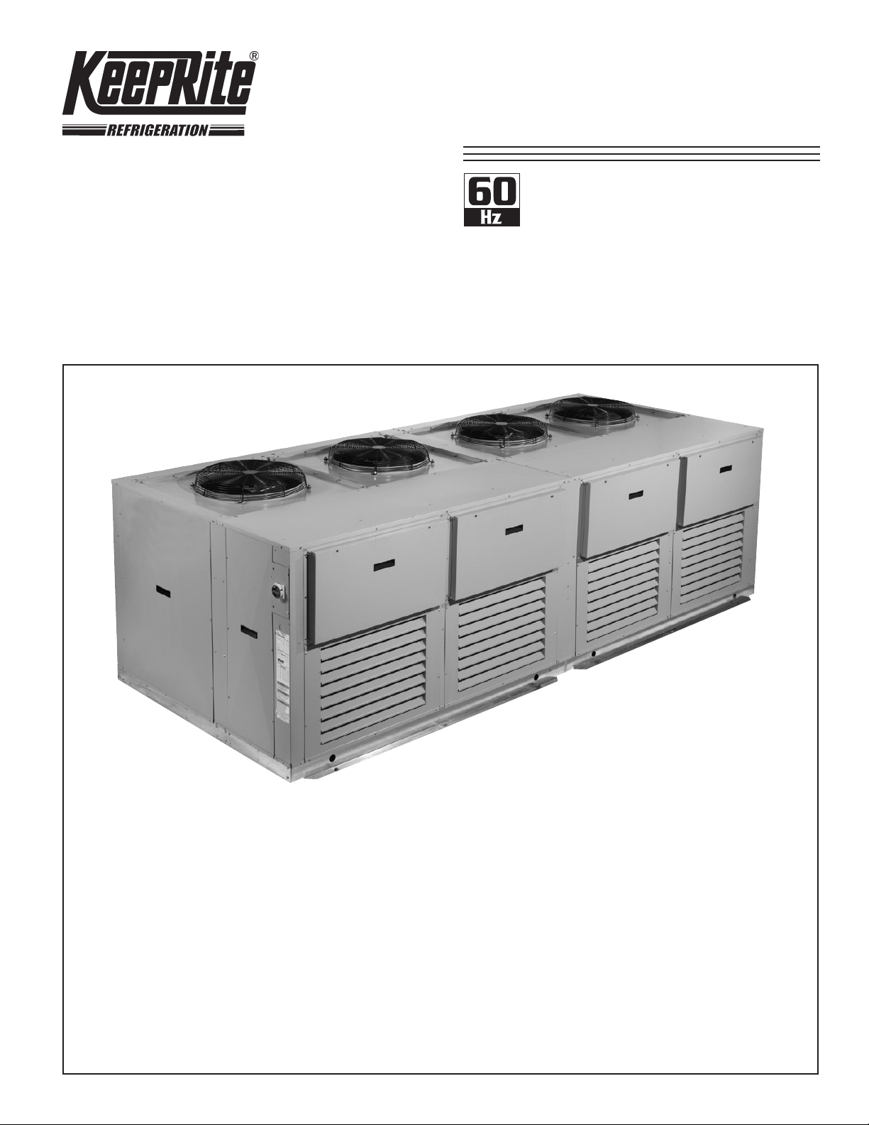
Outdoor
Multiple Compressor
Air Cooled
Condensing Units
1/2 to 10 HP Compressors
Hermetic, Scroll & Semi-Hermetic
Compressor (max. 40HP total)
CONTENTS
Page
Nomenclature ............................................................................................................... 2
Selection Process .......................................................................................................... 2
Features and Options .................................................................................................... 3
Compressor Selections ................................................................................................. 4 - 7
Electrical Data ............................................................................................................... 8 - 11
Dimensional Data (Unit and Pitch Pocket) .................................................................... 12 - 14
Wiring Diagrams............................................................................................................ 15 - 16
Specication and Submittal Drawing Worksheet .......................................................... 17
Warranty ....................................................................................................................... 19
Project Information ........................................................................................................ 19
“As Built” Service Parts List ........................................................................................... Back
Page 2
NOMENCLATURE
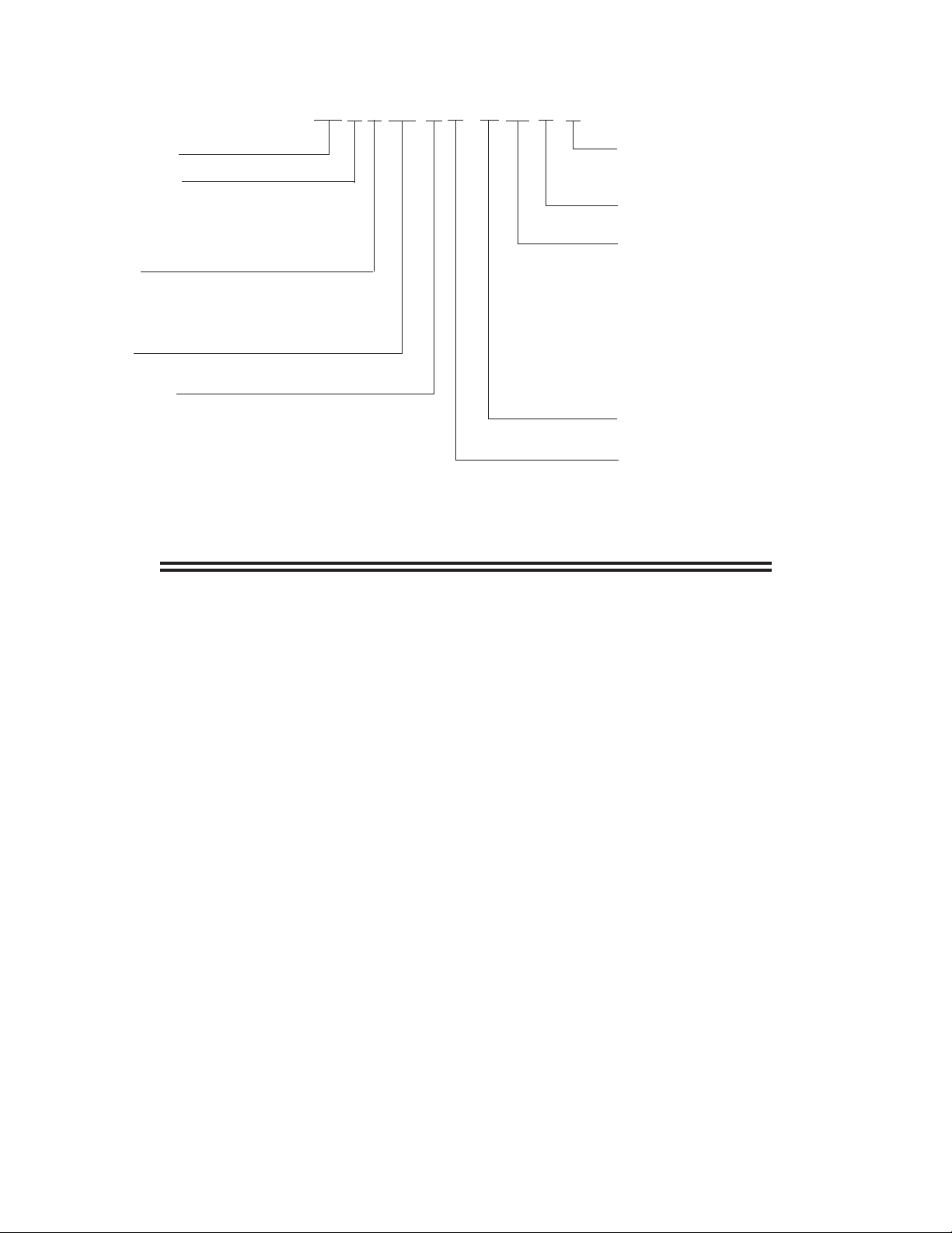
K40-KF-PDS-12
- 2 -
07/26/10
KF H T 240 H 6 - H T3 B - S
KF = Model Series
Compressor Type
H = Hermetic compressor
Z = Scroll Compressor
S = Semi-hermetic Compressor
M = Mixture of above
Cabinet Size
S = Single fan Section - maximum 6 HP
D = Double fan Section - maximum 12 HP
T = Triple fan section - maximum 18 HP
Q = Quadruple fan section - maximum 24 HP
Nominal HP
240 = 24 HP
Application Range
H = High and Med Temp (0 to 45°F evap temp)
M = Med Temp (0 to 30 °F evap temp)
L = Low Temp (-40 to 0 °F evap temp)
E = Extended Medium Temp (-20 to 30 °F evap temp)
* Subject to compressor availability
** Depends on application and compressor type
Cabinet Size
S = Small (6 HP Max per Section)
M = Medium (8-10 HP Max per Section) **
Series / Generation
B = Generation Designation
Voltage *
S2 = 208/230/1/60 *
S3 = 230/1/60 *
S6 = 200-220/1/50 *
S7 = 200/1/50*
T3 = 208-230/3/60
T4 = 460/3/60
T5 = 575/3/60
T7 = 200-220/3/50
T9 = 380-400/3/50
Enclosure
H = Outdoor
Refrigerant
2 = R22 , 6 = R404A / R507 , 7 = R407C
9 = Mixed appl. R22 and R404A / R507
SELECTION PROCESS
1) Select Compressor Models:
Select your compressor models (Capacity and HP) using the compressor specications on pages
4 thru 7. This can be a combination of:
• any refrigerant (R22 or R404A)
• any application (High, Medium or Low Temperature)
• any type of compressor (Hermetic, Scroll or Semi-Hermetic)
Make note of the points indicated in the table for each compressor.
2) Select the Cabinet:
Select the cabinet using the following guidelines:
• Maximum 6 points per fan section for small size.
Maximum 9 points per fan section for medium size.
• Maximum 3 compressors per fan section. Based on 95º F (35º C) design ambient.
• Maximum 4 fan sections.
3) Select the Unit Model Number:
Refer to the nomenclature chart above.
See page 17 for a Specication and Submittal Drawing Worksheet
Consult factory for any special requirements.
Page 3

STANDARD FEATURES
K40-KF-PDS-12
- 3 -
07/26/10
• Total system exibility using multiple compressor
models and applications on a common chassis.
• Up to four fan section cabinet choices of either
Hermetic, Scroll or Semi-Hermetic multiple
compressors, with maximum three compressors
per fan section.
• Small Cabinet: Compressor sizes available
ranging from 1/2 through 6 HP to a maximum
total of 6 HP per Fan section and 24 HP per unit.
(Based on 95°F design Ambient)
• Medium Cabinet: Compressor sizes available
ranging from 1/2 through 8-10* HP to a maximum
total of 8 HP per fan section and 40* HP per unit.
(Based on 95°F design Ambient)
• Semi-hermetic use suction and discharge vibration
eliminators and spring mounts.
* Depends on application and compressor type
• High efciency enhanced tube and n on both
indoor or outdoor condenser design using high
efciency PSC fan motors
• Outdoor unit uses weather-resistant housing with
hinged hood, weatherproof electrical panel and
xed head pressure ooding valve
• Each compressor includes main power fuse block,
contactor, xed high and low pressure control oil
pressure control (where applicable) and fused
control circuit
• Compressor circuit breaker (per compressor)
• Single Point Main electrical panel with non-
fused disconnect. (Single point dependant on
evaporator voltage)
• Includes liquid line drier and sightglass
OPTIONAL COMPONENTS (Factory mounted)
• Sealed Suction Filter
• Suction accumulator **
• Discharge line check valve
• Receiver Inlet ball valve
• Heated and insulated receiver
• Field piping connections at left or right side
• Flex hoses for pressure controls
• Voltage /Phase monitor
• Main disconnect fusing
** for semi-hermetic compressors- maximum one suction accumulator per fan section
• Compressor anti short cycle time delay relay
• Current sensing relay -for use with Oil control
(where applicable)
• Sentronic oil pressure control (where applicable)
• OMB oil level Control (where applicable)
• Air or Electric Defrost Kits
• Pumpdown toggle switch
• Liquid Line solenoid valve-with standard 230V
coil (shipped loose)
• Spare condenser circuit for remote ice machine
OTHER OPTIONS AVAILABLE UPON REQUEST.
CONSULT FACTORY FOR DETAILS
Page 4
H
K40-KF-PDS-12
- 4 -
07/26/10
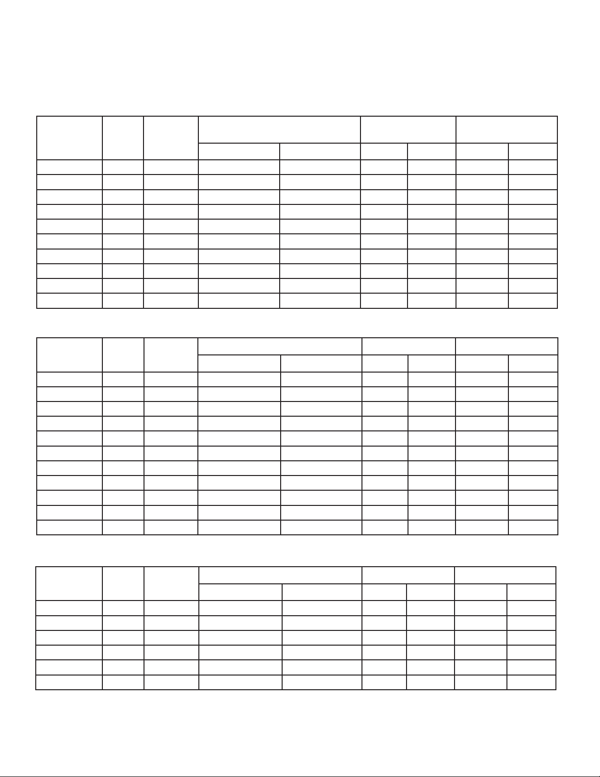
HERMETIC
COMPRESSOR SELECTIONS
HERMETIC
H2 - High/Medium Temperature - R22
60Hz
NOMINAL
COMPRESSOR HPPOINTS
1/2 1 ART82-C1 5970 (1749) 8300 (2431) 1/2 3/8 6 12.5
3/4 1 RS64C2 8090 (2370) 10800 (3163) 5/8 3/8 6 12.5
1 1 RS70C1 8870 (2598) 12200 (3573) 5/8 3/8 6 12.5
1 1/2 2 CR18KQ 13000 (3808) 18600 (5448) 5/8 3/8 12.5 16
2 2 CR24KQ 16100 (4716) 22300 (6532) 5/8 3/8 12.5 16
2 1/2 2.5 CR32KQ 21800 (6385) 29400 (8611) 7/8 3/8 16 34.5
3 3.5 CR37KQ 26600 (7791) 36400 (10662) 7/8 1/2 24.7 34.5
3 1/2 3.5 CR41KQ 29300 (8582) 40100 (11745) 7/8 1/2 24.7 34.5
4 4 CR53KQ 36200 (10603) 49000 (14352) 1 1/8 1/2 24.7 34.5
5 5 CRN5-0500 43900 (12858) 59000 (17281) 1 1/8 1/2 24.7 34.5
COPELAND
MODEL
NOMINAL CAPACITY - BTU/H (WATTS)* FIELD CONNECTIONS RECEIVER (90% Lbs)
25 °F (-3.9 °C) 40 °F (7.2 °C) SUCTION LIQUID STANDARD OVERSIZE
E6 - Extended Medium Temperature - R404A
NOMINAL
COMPRESSOR HPPOINTS
1/2 1 RST45C1E 2740 (803) 6310 (1848) 5/8 3/8 5.4 11.3
3/4 1 RST55C1E 3330 (975) 7340 (2150) 5/8 3/8 5.4 11.3
3/4 + 1 RST64C1E 4030 (1180) 8610 (2522) 5/8 3/8 5.4 11.3
1 1 RS70C1E 4010 (1175) 9490 (2780) 5/8 3/8 5.4 11.3
1 1/2 2 CS10K6E 5350 (1567) 15200 (4452) 5/8 3/8 11.3 14.4
2 2 CS12K6E 6310 (1848) 17400 (5096) 5/8 3/8 11.3 14.4
2 1/2 2.5 CS14K6E 8070 (2364) 20300 (5946) 7/8 1/2 14.4 21.5
3 3.5 CS18K6E 10160 (2976) 27700 (8113) 7/8 1/2 21.5 31
3 1/2 3.5 CS20K6E 11680 (3421) 30800 (9021) 7/8 1/2 21.5 31
4 4.5 CS27K6E 14900 (4364) 37900 (11101) 7/8 1/2 21.5 31
5 5 CS33K6E 18100 (5301) 43700 (12800) 7/8 1/2 21.5 31
COPELAND
MODEL
NOMINAL CAPACITY - BTU/H (WATTS) * FIELD CONNECTIONS RECEIVER (90% Lbs)
-10 °F (-23.3 °C) 25 °F (-3.9 °C) SUCTION LIQUID STANDARD OVERSIZE
L6 - Low Temperature - R404A
COMPRESSOR HPPOINTS
* At 95 °F (35 °C) Ambient
Refer to Bulletin K40-KEH-PDS-60 for further capacity data.
NOMINAL
1/2 1 AFT22C1E 2090 (612) 2730 (800) 1/2 3/8 5.4 11.3
3/4 1 AFT26C1E 2550 (747) 3380 (990) 1/2 3/8 5.4 11.3
1 1 CF04K6E 3710 (1087) 5150 (1508) 5/8 3/8 5.4 11.3
2 2 CF06K6E 5910 (1731) 8100 (2372) 7/8 3/8 11.3 14.4
2 1/2 2.5 CF09K6E 9100 (2665) 12500 (3661) 7/8 3/8 11.3 14.4
3 3 CF12K6E 11600 (3398) 15200 (4452) 7/8 1/2 14.4 21.5
COPELAND
MODEL
NOMINAL CAPACITY - BTU/H (WATTS) * FIELD CONNECTIONS RECEIVER (90% Lbs)
-20 °F (-28.9 °C) -10 °F (-23.3 °C) SUCTION LIQUID STANDARD OVERSIZE
Page 5
Z
K40-KF-PDS-12
- 5 -
07/26/10
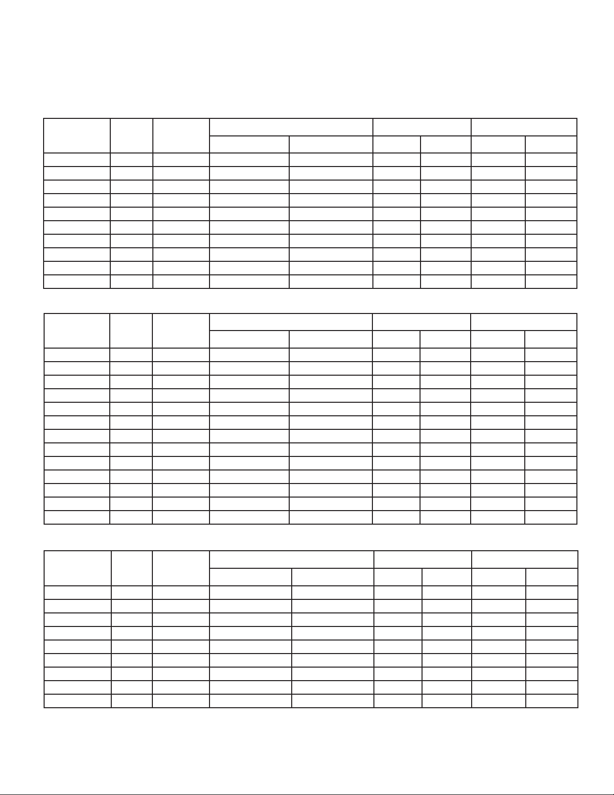
SCROLL
COMPRESSOR SELECTIONS
SCROLL
H2 - High/Medium Temperature - R22
60Hz
NOMINAL
COMPRESSOR HPPOINTS
2 2 ZB15KCE 18200(5331) 23800(6971) 7/8 3/8 13 16
2 1/2 2.5 ZB19KCE 20700(6063) 27200(7967) 7/8 3/8 16 24.7
3 3.5 ZB21KCE 27400(8025) 36200(10603) 1 1/8 1/2 24.7 34.5
3 1/2 3.5 ZB26KCE 31300(9168) 41000(12009) 1 1/8 1/2 24.7 34.5
4 4 ZB30KCE 36000(10544) 47100(13796) 1 1/8 1/2 24.7 34.5
5 5 ZB38KCE 44400(13005) 58200(17047) 1 1/8 34.5 62 34.5
6 6 ZB45KCE 53900(15787) 71000(20796) 1 1/8 5/8 34.5 50
6.5 7 ZB50KCE 58400(17105) 77800 (22788) 1 1/8 5/8 34.5 62
7 8 ZB58KCE 65100(19068) 86100 (25219) 1 3/8 5/8 62 87
7.5 + 9 ZB66KCE 77100(22583) 101800 (29817) 1 3/8 5/8 62 87
COPELAND
MODEL
NOMINAL CAPACITY - BTU/H (WATTS) * FIELD CONNECTIONS RECEIVER (90% Lbs)
25 °F (-3.9 °C) 40 °F (7.2 °C) SUCTION LIQUID STANDARD OVERSIZE
M6 - Medium Temperature - R404A
NOMINAL
COMPRESSOR HPPOINTS
1 1.5 ZB10KCE 8340 (2443) 12200 (3573) 5/8 3/8 11.3 14.4
1.1 2 ZB11KCE 9150 (2680) 13400 (3925) 7/8 3/8 11.3 14.4
1.5 2 ZB13KCE 10900 (3193) 16300 (4774) 7/8 3/8 11.3 14.4
2 2 ZB15KCE 12600 (3691) 18200 (5331) 7/8 3/8 11.3 14.4
2 1/2 2.5 ZB19KCE 15700 (4599) 24600 (7205) 7/8 1/2 14.4 21.5
3 3.5 ZB21KCE 19500 (5712) 28400 (8318) 1 1/8 1/2 21.5 31
3 1/2 3.5 ZB26KCE 22400 (6561) 35300 (10339) 1 1/8 1/2 21.5 31
4 4 ZB30KCE 24800 (7264) 39500 (11570) 1 1/8 1/2 21.5 31
5 5 ZB38KCE 31500 (9226) 49300 (14440) 1 1/8 1/2 31 54
6 6 ZB45KCE 38100 (11159) 60100 (17603) 1 3/8 5/8 31 54
6.5 7 ZB50KCE 40700 (11921)
7 8 ZB58KCE 43700 (12800) 63900 (18716) 1 3/8 5/8 54 76
7.5 + 9 ZB66KCE 54900 (16080) 79400 (23256) 1 3/8 5/8 54 76
COPELAND
MODEL
NOMINAL CAPACITY - BTU/H (WATTS) * FIELD CONNECTIONS RECEIVER (90% Lbs)
5 °F (-15 °C) 25 °F (-3.9 °C) SUCTION LIQUID STANDARD OVERSIZE
59800 (17515) 1 3/8 5/8 31 54
L6 - Low Temperature - R404A
COMPRESSOR HPPOINTS
* At 95 °F (35 °C) Ambient
Refer to Bulletin K40-KEZ-PDS-60 for further capacity data.
NOMINAL
2 2 ZF06K4E 7800 (2285) 9600 (2812) 7/8 3/8 11.3 14.4
2 1/2 2.5 ZF08K4E 9900 (2900) 12200 (3573) 7/8 3/8 14.4 21.5
3 3 ZF09K4E 11000 (3222) 13500 (3954) 7/8 3/8 14.4 21.5
3 1/2 3 ZF11K4E 13300 (3896) 16300 (4774) 1 1/8 1/2 14.4 21.5
4 1/2 4 ZF13K4E 15400 (4511) 19200 (5624) 1 1/8 1/2 21.5 31
5 1/2 4 ZF15K4E 18800 (5507) 23100 (6766) 1 1/8 1/2 21.5 31
6 5 ZF18K4E 22800 (6678) 28000 (8201) 1 3/8 1/2 31 54
7 1/2 6 ZF24K4E 27900 (8172) 31100 (9109) 1 3/8 5/8 54 76
10 8 ZF33K4E 38100 (11159) 42400 (12419) 1 3/8 5/8 54 76
COPELAND
MODEL
NOMINAL CAPACITY - BTU/H (WATTS) * FIELD CONNECTIONS RECEIVER (90% Lbs)
-20 °F (-28.9 °C) -10 °F (-23.3 °C) SUCTION LIQUID STANDARD OVERSIZE
Page 6
S
K40-KF-PDS-12
- 6 -
07/26/10
SEMI-HERMETIC
COMPRESSOR SELECTIONS
SEMI-HERMETIC
H2 - High/Medium Temperature - R22
60Hz
NOMINAL
COMPRESSOR HPPOINTS
3/4 1 KAN-0075 6920 (2027) 9420 (2759) 1/2 3/8 6 12.5
1 1.5 KAR-0100 9530 (2791) 12800 (3749) 5/8 3/8 6 12.5
1 1/2 2 KAG-0150 12000 (3515) 16500 (4833) 7/8 3/8 16 24.7
2 2 KAK-0200 16600 (4862) 22400 (6561) 7/8 1/2 16 24.7
3 3.5 ERF-0310 27110 (7941) 36650 (10735) 1 1/8 1/2 24.7 34.5
5 5.5 2DC3-0500 44280 (12970) 60330 (17671) 1 3/8 5/8 34.5 50
5+ 6 2DD3-0500 50650 (14835) 68350 (20020) 1 3/8 5/8 34.5 50
7 1/2 8 2DL3R78KE 62010 (18163) 82390 (24132) 1 3/8 5/8 62 87
7 3/4 9 2DA3R89KE 68890 (20178) 90580 (26531) 1 3/8 5/8 62 87
8+ 9 3DA3R10ME 86500 (25336) 114200 (33449) 1 3/8 5/8 62 87
COPELAND
MODEL
NOMINAL CAPACITY - BTU/H (WATTS) * FIELD CONNECTIONS RECEIVER (90% Lbs)
25 °F (-3.9 °C) 40 °F (7.2 °C) SUCTION LIQUID STANDARD OVERSIZE
M2 - Medium Temperature - R22
NOMINAL
COMPRESSOR HPPOINTS
3/4 1 KAE-0075 6050 (1772) 7560 (2214) 5/8 3/8 6 12.5
1 1.5 KAM-0100 8450 (2475) 10600 (3105) 5/8 3/8 6 12.5
2 2 ERC-0200 14300 (4188) 18300 (5360) 7/8 1/2 16 24.7
COPELAND
MODEL
NOMINAL CAPACITY - BTU/H (WATTS) * FIELD CONNECTIONS RECEIVER (90% Lbs)
15 °F (-9.4 °C) 25 °F (-3.9 °C) SUCTION LIQUID STANDARD OVERSIZE
M6 - Medium Temperature - R404A
NOMINAL
COMPRESSOR HPPOINTS
3/4 1 KAN-007E 4100 (1201) 6550 (1918) 1/2 3/8 5.2 11.3
1 1.5 KAR-010E 6300 (1845) 9360 (2742) 5/8 3/8 5.2 11.3
1 1/2 2 KAG-010E 7800 (2285) 11200 (3280) 5/8 3/8 11.3 14.4
2 2 KAK-020E 10200 (2988) 15400 (4511) 7/8 1/2 14.4 21.5
2 + 2.5 ERC-021E 12700 (3720) 19400 (5682) 7/8 1/2 14.4 21.5
3 3.5 ERF-031E 18700 (5477) 28360 (8307) 7/8 1/2 21.5 31
5 5.5 2DC3R53KE 29110 (8526) 45240 (13251) 1 1/8 5/8 31 54
5 6 2DD3R63KE 34540 (10117) 52880 (15489) 1 1/8 5/8 31 54
7 1/2 8 2DL3R78KE 41720 (12220) 62190 (18215) 1 3/8 5/8 54 76
7 1/2 9 2DA3R89KE 48040 (14071) 69480 (20351) 1 3/8 5/8 54 76
7 1/2 9 3DA3R10ME 57900 (16959) 85500 (25043) 1 3/8 5/8 54 76
* At 95 °F (35 °C) Ambient
Refer to Bulletin K40-KES-PDS-60 for further capacity data.
COPELAND
MODEL
NOMINAL CAPACITY - BTU/H (WATTS) * FIELD CONNECTION RECEIVER (90% Lbs)
5 °F (-15 °C) 25 °F (-3.9 °C) SUCTION LIQUID STANDARD OVERSIZE
Page 7

S
K40-KF-PDS-12
- 7 -
07/26/10
SEMI-HERMETIC
COMPRESSOR SELECTIONS (cont’d)
SEMI-HERMETIC
L6 - Low Temperature - R404A
60Hz
NOMINAL
COMPRESSOR HPPOINTS
1/2 1 KAN-005E 1960 (574) 2750 (805) 1/2 3/8 5.2 11.3
3/4 1 KAM-007E 3440 (1008) 4580 (1341) 5/8 3/8 5.2 11.3
1 1 KAJ-010E 4460 (1306) 5760 (1687) 7/8 3/8 5.2 11.3
1 1/2 1.5 KAL-015E 6910 (2024) 8960 (2624) 7/8 3/8 14.4 21.5
2 2 EAD-020E 7590 (2223) 10100 (2958) 7/8 3/8 14.4 21.5
2 2 EAV-020E 8770 (2569) 11400 (3339) 7/8 1/2 14.4 21.5
3 3 LAH-031E 13920 (4077) 18630 (5457) 1 1/8 1/2 21.5 31
3.1 3.5 LAC-032E 17140 (5020) - - 1 1/8 1/2 21.5 31
3 1/2 4 2DF3F16KE 18780 (5501) 24080 (7053) 1 1/8 1/2 21.5 31
4+ 5 2DL3F20KE 23110 (6769) 29510 (8643) 1 1/8 1/2 21.5 31
6 6 2DB3F25KE 28840 (8447)
6 6.5 3DA3F28KE 31980 (9367) 40480 (11857) 1 3/8 5/8 31 54
7 1/2 8 3DB3F33KE 37120 (10872) 46550 (13634) 1 3/8 5/8 54 76
9 9 3DF3-090E 46200 (13532) 58500 (17135) 1 3/8 5/8 54 76
* At 95 °F (35 °C) Ambient
Refer to Bulletin K40-KES-PDS-60 for further capacity data.
COPELAND
MODEL
NOMINAL CAPACITY - BTU/H (WATTS) * FIELD CONNECTIONS RECEIVER (90% Lbs)
-20 °F (-28.9 °C) -10 °F (-23.3 °C) SUCTION LIQUID STANDARD OVERSIZE
36760 (10767) 1 3/8 5/8 31 44
Page 8

H
K40-KF-PDS-12
- 8 -
07/26/10
ELECTRICAL DATA
HERMETIC
H2 - High/Medium Temperature - R22
NOMINAL
COMPRESSOR HP
1/2 ART82-C1 5.3 30 - - - - - -
3/4 RS64C2 6.9 37 - - - - - -
1 RS70C1 6.3 34.2 4.2 31 2.6 15 - -
1 1/2 CR18KQ 8.1 41 5.4 49 3.1 23 - -
2 CR24KQ 12.2 70.5 6.7 51 3.3 25 - -
2 1/2 CR32KQ 15.3 83 8.8 63 4.6 32 - -
3 CR37KQ 16.7 100 9.9 85 5 39 - -
3 1/2 CR41KQ 17.4 109.6 11.8 80 5.3 42 - -
4 CR53KQ 26 140 16.3 107 8.1 55 - -
5 CRN5-0500 30.8 142 19.2 130 8.7 65 7.1 52
E6 - Extended Medium Temperature - R404A
NOMINAL
COMPRESSOR HP
1/2 RST45C1E 4.6 26.5 - - - - - -
3/4 RST55C1E 6.1 33.7 - - - - - -
3/4 + RST64C1E 8 43 - - - - - -
1 RS70C1E 6.3 34.2 4.2 31 2.6 15 - -
1 1/2 CS10K6E 9.8 56 6.7 51 3.2 25 - -
2 CS12K6E 9.8 56 6.7 51 - - - -
2 1/2 CS14K6E 11.2 61 8.2 55 4.2 28 - -
3 CS18K6E 14.4 82 7.9 65.5 4.2 33 - -
3 1/2 CS20K6E 16.7 96 10.2 75 4.6 40 - -
4 CS27K6E 21.5 95.4 14 82 7.6 41 - -
5 CS33K6E 27.6 125 16.8 102 8.8 48 - -
HERMETIC - COMPRESSOR (RLA/LRA)
COMPRESSOR
MODEL
COMPRESSOR
MODEL
208/230-1-60 208/230-3-60 460-3-60 575-3-60
RLA LRA RLA LRA RLA LRA RLA LRA
208/230-1-60 208/230-3-60 460-3-60 575-3-60
RLA LRA RLA LRA RLA LRA RLA LRA
60Hz
L6 - Low Temperature - R404A
COMPRESSOR HP
NOMINAL
1/2 AFT22C1E 3.3 32.5 - - - - - -
3/4 AFT26C1E 4.1 32.2 - - - - - -
1 CF04K6E 9.9 59.2 6.1 52 3.3 26 - -
2 CF06K6E 10.3 59.2 6.3 52 3.7 25.4 - -
2 1/2 CF09K6E 15 87 9.2 72.2 4.9 35.8 - -
3 CF12K6E 18.4 105 11 85 5.9 42 - -
COMPRESSOR
MODEL
208/230-1-60 208/230-3-60 460-3-60 575-3-60
RLA LRA RLA LRA RLA LRA RLA LRA
Page 9

Z
K40-KF-PDS-12
- 9 -
07/26/10
SCROLL
SCROLL COMPRESSOR (RLA/LRA)
ELECTRICAL DATA -
60Hz
H2 - High/Medium Temperature - R22 / M6 - Medium Temperature - R404A
NOMINAL
COMPRESSOR
HP
1 ZB10KCE 10 41 - - - - - -
1.1 ZB11KCE 10 45 - - - - - -
1.5 ZB13KCE 12.9 54 - - - - - -
2 ZB15KCE 15.7 61 8.9 55 5 27 - -
2 1/2 ZB19KCE 17.9 73 10 63 5 31 - -
3 ZB21KCE 20.7 100 12.1 77 6.1 39 5 31
3 1/2 ZB26KCE 20.7 127 13.9 88 7.1 44 5 34
4 ZB30KCE 26.8 132 15.7 115 7.5 47.5 6 38
5 ZB38KCE 31.1 175 22.1 115 9.6 63 7.7 50
6 ZB45KCE - - 22.5 156 11.5 70 9.2 56
6.5 ZB50KCE - - 28.6 196 15 100 11.1 90
7 ZB58KCE - - 32.1 195 16.4
7 1/2 ZB66KCE - - 33.6 225 17.5 114 13.5 80
COMPRESSOR
MODEL
208/230-1-60 208/230-3-60 460-3-60 575-3-60
RLA LRA RLA LRA RLA LRA RLA LRA
95 12.9 80
L6 - Low Temperature - R404A
NOMINAL
COMPRESSOR HP
2 ZF06K4E 13.6 61 9.3 55 4.3 27 - -
2 1/2 ZF08K4E 16.4 73 9.7 63 5 39 4 24
3 ZF09K4E 16.4 88 11.1 77 5.7 39 4.3 31
3 1/2 ZF11K4E 20.7 109 13.6 88 7.1 44 5 34
4 1/2 ZF13K4E 26.8 129 15 99 8.2 49.5 8.2 40
5 1/2 ZF15K4E 31.8 169 21.4 123 9.6 62 7.9 50
6 ZF18K4E - - 23.9 156 9.3 70 7.9 54
7 1/2 ZF24K4E - - 30 189 15.7 94 8.9 74
10 ZF33K4E - - 43.6 278 21.1 127 16.1 100
COMPRESSOR
MODEL
208/230-1-60 208/230-3-60 460-3-60 575-3-60
RLA LRA RLA LRA RLA LRA RLA LRA
Page 10

S
K40-KF-PDS-12
- 10 -
07/26/10
SEMI-HERMETIC
SEMI-HERMETIC COMPRESSOR
ELECTRICAL DATA -
(RLA/LRA)
H2 - High/Medium Temperature - R22
60Hz
NOMINAL
COMPRESSOR HP
3/4 KAN-0075 6.1 36 3.5 19.9 - - - -
1 KAR-0100 7.4 40 4.3 27 2.2 13.5 - -
1 1/2 KAG-0150 9.6 55 5.5 35.5 2.5 18.2 - -
2 KAK-0200 10.6 55 6.8 50 3 25 - -
3 ERF-0310 17 86 11.7 82 6.4 41 - -
5 2DC3R53KE 29.9 125 22.3 120 10.4 60 7.7 49
5 2DD3R63KE - - 22.3 120 10.5 60 7.9 49
7 1/2 2DL3R78KE - - 31.6 169 13.8 85 13.2 67
7 3/4 2DA3R89KE - - 32 169 14.1 85 13.3 67
8 3DA3R10ME - - 41 215 20 106 16.5 84
COMPRESSOR
MODEL
208/230-1-60 208/230-3-60 460-3-60 575-3-60
RLA LRA RLA LRA RLA LRA RLA LRA
M2 - Medium Temperature - R22
NOMINAL
COMPRESSOR
HP
3/4 KAE-0075 5.4 36 3.4 19.9 - - - -
1 KAM-0100 7.5 40 4.5 27 2.2 13.5 - -
2 ERC-0200 10.9 58 6.8 46 3.6 23 3.2 20
COMPRESSOR
MODEL
208/230-1-60 208/230-3-60 460-3-60 575-3-60
RLA LRA RLA LRA RLA LRA RLA LRA
M6 - Medium Temperature - R404A
NOMINAL
COMPRESSOR HP
3/4 KAN-007E 5.4 36 3 19.9 - - - -
1 KAR-010E 7.4 40 4.3 27 2 15 - -
1 1/2 KAG-010E 7.5 40 4.3 27 2.2 15 - -
2 KAK-020E 10.6 55 6.8 50 3 25 - -
2.1 ERC-021E - - 8.8 46 3.5 23 3.1 20
3 ERF-031E 17 86 12.4 82 5.8 41 - -
5 2DC3R53KE - - 22.3 120 10.4 60 7.7 49
5 2DD3R63KE - - 22.3 120 10.5 60 7.9 49
7 1/2 2DL3R78KE - - 31.6 169 13.8 85 13.2 67
7 3/4 2DA3R89KE - - 32 169 14.1 85 13.3 67
8 3DA3R10ME - - 41 215 20 106 16.5 84
COMPRESSOR
MODEL
208/230-1-60 208/230-3-60 460-3-60 575-3-60
RLA LRA RLA LRA RLA LRA RLA LRA
Page 11

S
K40-KF-PDS-12
- 11 -
07/26/10
SEMI-HERMETIC
SEMI-HERMETIC COMPRESSOR
ELECTRICAL DATA -
L6 - Low Temperature - R404A
NOMINAL
COMPRESSOR HP
1/2 KAN-005E 3.6 24 2.2 13.2 - - - -
3/4 KAM-007E 5.6 36 3.2 19.9 - - - -
1 KAJ-010E 6.9 40 4.6 27 2.1 15 - -
1 1/2 KAL-015E 9.9 55 6.6 50 3.4 25 - -
2 EAD-020E 10 58 6.8 46 - - - -
2 EAV-020E 14.7 102 7.4 50 3.9 26.6 3.1 20
3 LAH-031E 16.7 105 12.8 112 6 56 4.1 30
3.1 LAC-032E 15.5 105 12.8 112 6 56 - -
3 1/2 2DF3F16KE 25.8 125 16.8 102 8.1 52 6.7 41
4 2DL3F20KE - - 26.3 161 10.2 60 7.7 49
6 2DB3F25KE - - 28.2 161 13.3 80 9.6 63
6 3DA3F28KE - - 30.3 150 13.7 77
7 1/2 3DB3F33KE - - 31.5 161 16.1 83 11 67
9 3DF3-090E - - 37 215 16.7 106 15.7 84
COMPRESSOR
MODEL
208/230-1-60 208/230-3-60 460-3-60 575-3-60
RLA LRA RLA LRA RLA LRA RLA LRA
60Hz
(RLA/LRA) (cont’d)
10.5 62
STANDARD PSC MOTOR (FLA) DATA
UNIT
VOLTAGE
208/230-1-60 2.1 4.2 6.3 8.4 3.6 7.2 10.8 14.4
208/230-3-60 2.1 4.2 6.3 8.4 3.6 7.2 10.8 14.4
460-3-60 1.1 2.2 3.3 4.4 1.7 3.4 5.1 6.8
575-3-60 0.9 1.8 2.7 3.6 1.4 2.8 4.2 5.6
1 FAN 2 FAN 3 FAN 4 FAN 1 FAN 2 FAN 3 FAN 4 FAN
TOTAL FAN FLA (Small Cabinet) TOTAL FAN FLA (Medium Cabinet)
Page 12

DIMENSIONAL DATA - Small Chassis
K40-KF-PDS-12
- 12 -
07/26/10
Page 13

DIMENSIONAL DATA - Medium Chassis
K40-KF-PDS-12
- 13 -
07/26/10
60 5/16
7 29/32
7 29/32
30
MTG CTR
45 27/32
70
MTG CTR
85 27/32
84
MTG CTR
7 29/32
7 29/32 70
55
MTG CTR
MTG CTR
125 27/32
55
MTG CTR
171 21/32
70
MTG CTR
Page 14
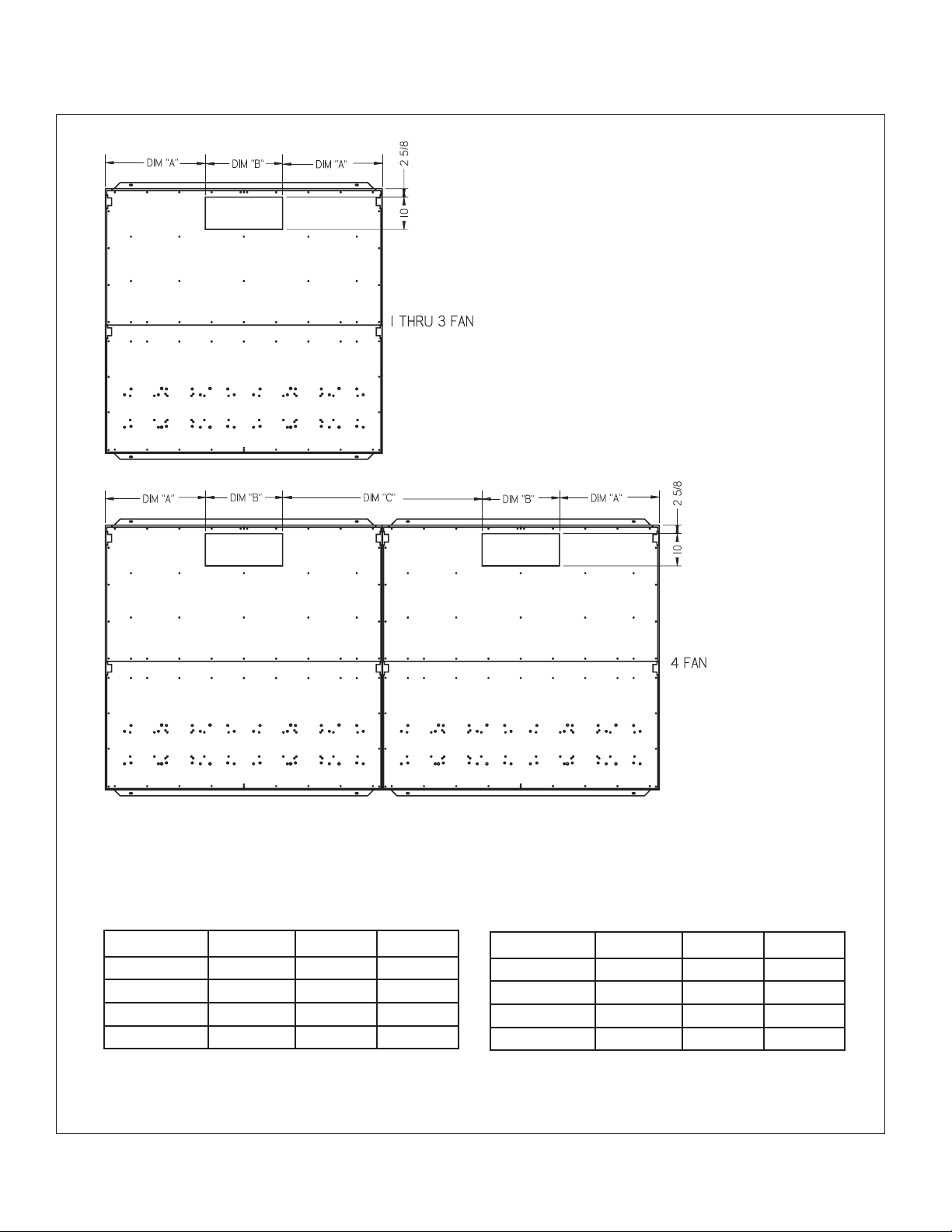
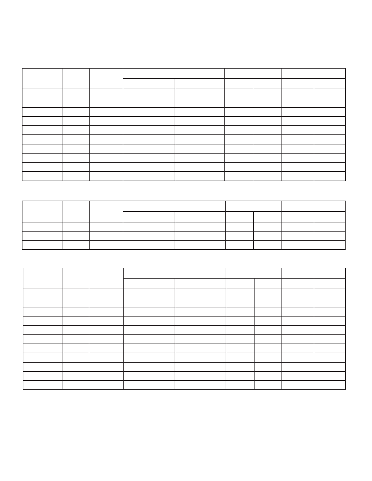
DIMENSIONS - PITCH POCKET
K40-KF-PDS-12
- 14 -
07/26/10
SMALL CHASSIS MEDIUM CHASSIS
DIM “A” DIM “B” DIM “C”
1 FAN WIDE 15 13/32″ 12″ N/A
2 FANS WIDE 28 9/32″ 24″ N/A
3 FANS WIDE 44 5/32″ 30″ N/A
4 FANS WIDE 29 9/32″ 24″ 56 19/32″
1 FAN WIDE 16 29/32″ 12″ N/A
2 FANS WIDE 30 29/32″ 24″ N/A
3 FANS WIDE 47 29/32″ 30″ N/A
4 FANS WIDE 30 29/32″ 24″ 61 27/32″
DIM “A” DIM “B” DIM “C”
Page 15

WIRING DIAGRAM
K40-KF-PDS-12
- 15 -
07/26/10
Page 16
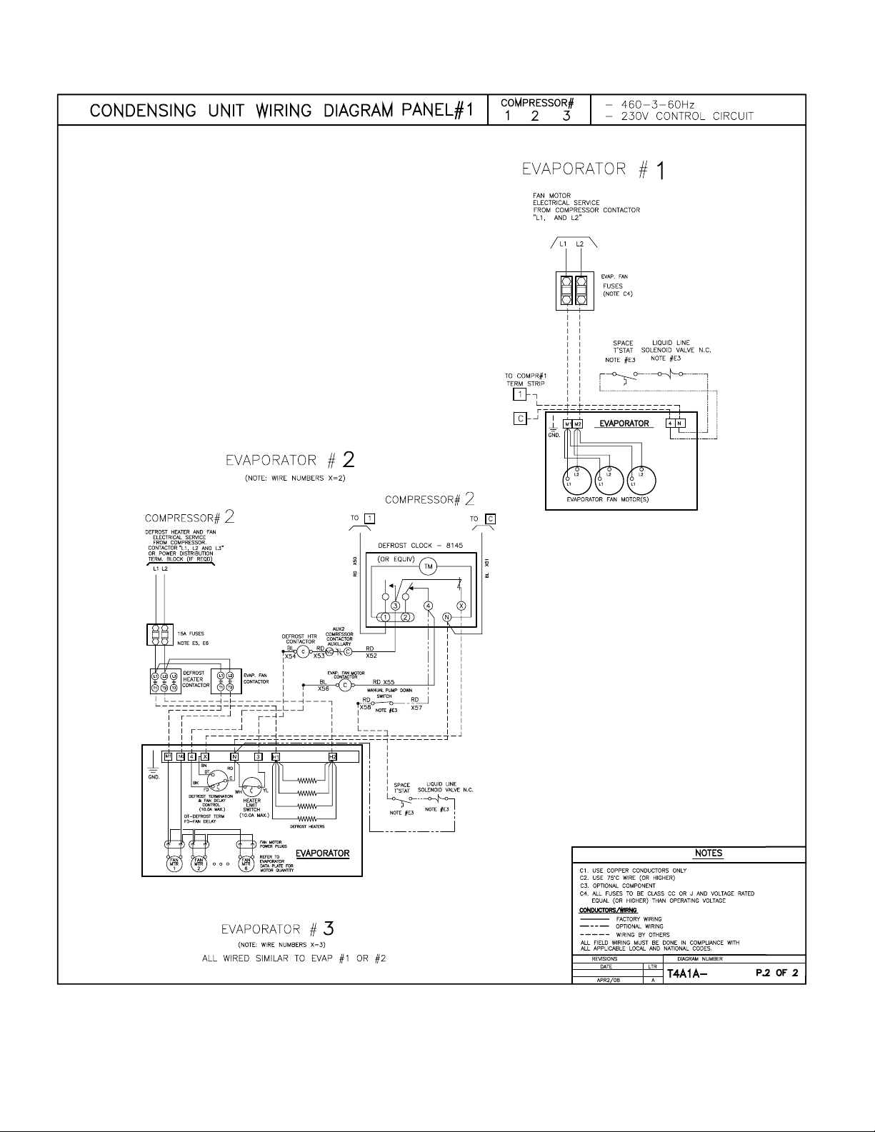
WIRING DIAGRAM
K40-KF-PDS-12
- 16 -
07/26/10
Page 17

12
K40-KF-PDS-12
- 17 -
07/26/10
10
11
9
6
7
8
3
4
5
ITEM DESCRIPTION LBS @ 90% SUCTION LIQUID
1
2
12
10
11
9
6
7
8
3
4
5
ITEM DESCRIPTION ROOM VOLTAGE FLA VOLTAGE AMPS
1
2
Revision
Level:
Date:
RECEIVER CAPACITY FIELD CONNECTIONS
MANUFACTURER
COMPRESSOR
SPECIFICATION AND SUBMITTAL DRAWING WORKSHEET
MULTI-COMPRESSOR AIR COOLED CONDENSING UNIT
QTY. MODEL HP
* Unit Model
TYPE
REF.
COMPRESSOR DATA EVAPORATOR COILS
Number:
Project:
Height: _____
Depth: _____
FAN QTY. HP (each) VOLTAGE TOTAL FLA BLADE DIA.
UNIT DIMENSIONS AND WEIGHT
CONDENSER MOTOR AND BLADE DATA
1/3 22”
MCA = Minimum Circuit Ampacity
MOP = Maximum Overcurrent Protection
* Unit Model Number subject to change
Est. Weight (lbs.):
Width:
SST BTUH VOLTAGE RLA DEFROST QTY.
MODEL
COIL
FAN MOTORS
DEFROST HEATERS
MOP:
MCA:
Unit Voltage:
Page 18

NOTES
K40-KF-PDS-12
- 18 -
07/26/10
Page 19

FINISHED GOODS WARRANTY
K40-KF-PDS-12
- 19 -
07/26/10
The terms and conditions as described below in the General Warranty Policy cover all products
manufactured by National Refrigeration.
GENERAL WARRANTY POLICY
Subject to the terms and conditions hereof, the Company warrants all Products, including Service
Parts, manufactured by the Company to be free of defects in material or workmanship, under normal use and application for a period of one (1) year from the original date of installation, or eighteen
(18) months from the date of shipment from the Company, whichever occurs rst. Any replacement
part(s) so supplied will be warranted for the balance of the product’s original warranty. The part(s) to
be replaced must be made available in exchange for the replacement part(s) and reasonable proof
of the original installation date of the product must be presented in order to establish the effective
date of the warranty, failing which, the effective date will be based upon the date of manufacture plus
thirty (30) days. Any labour, material, refrigerant, transportation, freight or other charges incurred in
connection with the performance of this warranty will be the responsibility of the owner at the current rates and prices then in effect. This warranty may be transferred to a subsequent owner of the
product.
THIS WARRANTY DOES NOT COVER
(a) Damages caused by accident, abuse, negligence, misuse, riot, re, ood, or Acts of God (b) damages
caused by operating the product in a corrosive atmosphere (c) damages caused by any unauthorized
alteration or repair of the system affecting the product’s reliability or performance (d) damages caused
by improper matching or application of the product or the product’s components (e) damages caused by
failing to provide routine and proper maintenance or service to the product (f) expenses incurred for the
erecting, disconnecting, or dismantling the product (g) parts used in connection with normal maintenance,
such as lters or belts (h) products no longer at the site of the original installation (i) products installed
or operated other than in accordance with the printed instructions, with the local installation or building
codes and with good trade practices (j) products lost or stolen.
No one is authorized to change this WARRANTY or to create for or on behalf of the Company any
other obligation or liability in connection with the Product(s). There is no other representation, warranty
or condition in any respect, expressed or implied, made by or binding upon the Company other than
the above or as provided by provincial or state law and which cannot be limited or excluded by such
law, nor will we be liable in any way for incidental, consequential, or special damages however caused.
The provisions of this additional written warranty are in addition to and not a modication of or subtraction
from the statutory warranties and other rights and remedies provided by Federal, Provincial or State laws.
PROJECT INFORMATION
Sy st em
Mo de l Number Da te of Start-U p
Se ri al Number Se rv ice Contrac to r
Re fr igerant Ph on e
El ec trical Supp ly Fa x
Page 20

“AS BUILT” SERVICE PARTS LIST
07/26/10
Service Parts List
Label
To Be Attached
HERE
NATIONAL REFRIGERATION &
AIR CONDITIONING CANADA CORP.
CANADA
159 ROY BLVD., BRANTFORD, ONTARIO, CANADA N3R 7K1
PHONE: 1-800-463-9517 (519)751-0444 FAX (519)753-1140
Due to National Refrigeration’s policy of continuous product improvement, we reserve the right to make changes without notice.
USA
985 WHEELER WAY, LANGHORNE, PA. 19047 USA
PHONE:1-888-KEEPUS1 OR 1-888-533-7871
 Loading...