

Page 1
PRODUCT DATA &
INSTALLATION
Bulletin K60-KDF-PDI-10
1064436
We are on the Internet
www.keepriterefrigeration.com
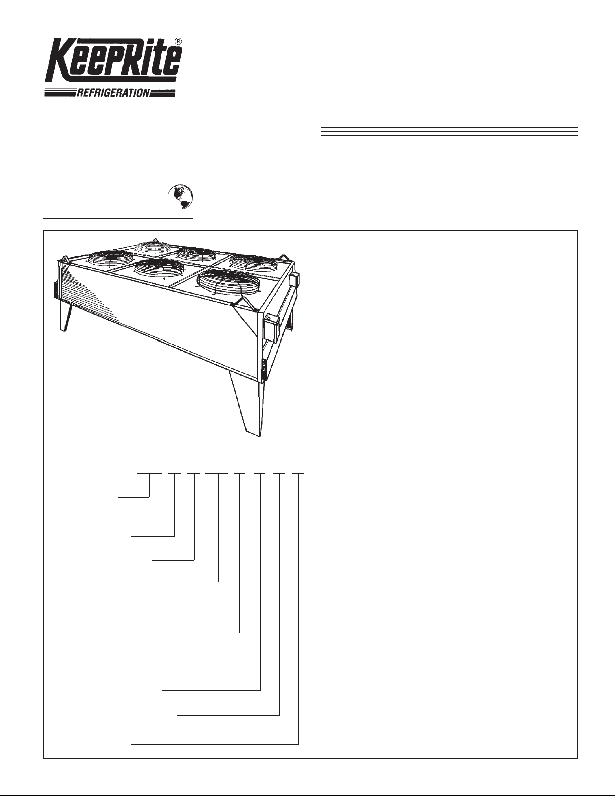
KDF Direct Drive
Dry Type
Fluid Coolers
Air Cooled Models from 200 MBH
to 2,000 MBH
One to Six fan Units Glycol Selection Data
• Heavy gauge galvanized steel casing with zinc
plated nuts and bolts
• Die-formed legs
• High efficiency coils with rippled aluminum fins
hydraulically bonded to copper tubing.
NOMENCLATURE
KDF A 1 075 D 2 A T
KEEPRITE
DIRECT DRIVE
FLUID COOLER
GENERA TION
NUMBER OF FANS
PRODUCT OF ROW DEPTH
AND SQ. FT . OF F ACE AREA
EG. 5 ROW DEEP x 15.0
SQ. FT. = MODEL No. 075
ELECTRICAL DESIGNA TION
D = 208-230/1/60
F = 208-230/3/60
K = 460/3/60
L = 575/3/60
CONTROL OPTIONS
0 TO 6
CONNECTION OPTIONS
A TO D (BLANK SIGNIFIES NO FLANGES)
• Four-bladed heavy gauge rust resistant aluminum
fans with steel spider and hub.
• Direct drive fan motors with inherent overload
protection.
• Motors are weather protected by top end rain
shields and shaft moisture slingers.
CONTENTS PAGE
Nomenclature.........................................
Capacity Data.........................................
Selection Data Notes............................
Sample Selection..................................
Dimensional Data..................................
Installation Instructions........................
Design Specifications...........................
Service Log............................................
Project Information...............................
Cover
2
2
3, 4, 5
6
7, 8
Back
Back
Back
TEAC MOTOR
Page 2
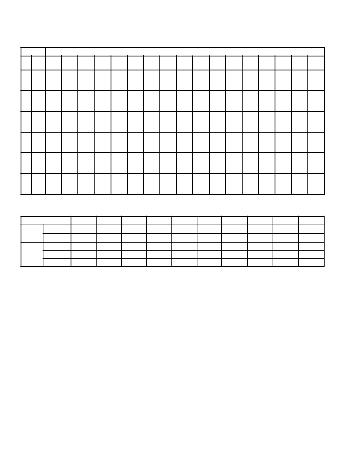
CAPACITY DATA
M.B.H. / SQ. FT. COIL FACE AREA
Table 1
Approach INITIAL TEMPERATURE DIFFERENCE (I.T.D.)
20°F
25°F
30°F
35°F
40°F
45°F
50°F
55°F
60°F
65°F
11.6
14.1
15.7
17.2
18.4
19.4
20.3
21.2
21.9
23.2
70°F
(39°C)
12.3
15.0
16.6
18.3
19.4
20.5
21.5
22.4
23.2
23.9
24.5
25.0
(42°C)
°F °C
5
10
15
20
11
25
14
30
17
35
19
40
22
45
25
50
28
55
30
60
33
65
36
70
39
75
42
80
44
85
47
90
50
(11°C)
(14°C)
(17°C)
(19°C)
(22°C)
(25°C)
(28°C)
(30°C)
(33°C)
(36°C)
3
4.9
5.7
6.6
7.5
8.1
8.8
9.5
10.2
10.9
6
6.1
7.0
8.0
8.9
9.9
10.8
11.7
12.5
13.3
8
8.0
9.1
10.0
9.9 11.0
11.7
11.2
12.1
13.0
13.7
12.1
13.1
13.1
14.1
14.0
15.0
14.8
16.0
15.5 16.7
17.5
14.0
15.1
16.2
17.2
17.9
18.7
19.3
14.9
16.2
17.4
18.4
19.2
20.0
20.6
21.2 22.5
75°F
80°F
(44°C)
13.1
13.9
15.7
16.4
17.5
18.5
19.1
20.0
20.4
21.4
21.5
22.7
22.6
23.7
23.5
24.6
24.3
25.4
25.0
26.2
25.7
27.0
26.2
27.5
27.0 28.1
28.7
85°F
(47°C)
14.5
17.2
19.3
20.8
22.9
23.5
24.7
25.6
26.5
27.3
28.1
28.7
29.4
30.0
30.7
90°F
95°F
(50°C)
(53°C)
15.2
18.1
20.2
21.8
23.3
24.5
25.6
26.6
27.6
28.5
29.3
30.0
30.7
31.4
32.0
32.6 33.9
15.9
18.8
20.9
22.6
24.1
25.4
26.6
27.7
28.6
29.5
30.4
31.1
31.8
32.5
33.2
34.6
100°F
(55°C)
16.7
19.6
21.7
23.5
25.0
26.4
27.5
28.5
29.5
30.5
31.4
32.3
33.0
33.7
34.4
35.1
35.8
36.5
COIL FACE AREA
Table 1A
Model KDF 1052 1060 2100 2120 3152 3180 4200 4240 6300 6360
Coil
Face
Area
Fan
Data
Data shown covers 10 models. 10 additional models available. Consult your local KeepRite Refrigeration Sales Office.
1. Temperature Limitations
2. Elevation Adjustment
3. Ratings
Sq. Ft. 12.5 15.0 25.0 30.0 37.5 45.0 50.0 60.0 75.0 90.0
2
m
1.16 1.39 2.32 2.79 3.48 4.18 4.65 5.57 6.97 9.36
No. 1 1 2 2 3 3 4 4 6 6
Total CFM 7050 7380 14100 14760 21150 22140 28200 29520 42300 44280
Total m3/s 3.33 3.48 6.65 6.97 9.98 10.45 13.31 13.93 19.96 20.9
KeepRite fluid coolers are suitable for leaving air
temperatures up to a maximum of 130°F (54°C).
Fluid temperature up to an average of 150°F (66°C)
selection programme is available. Interpolation of
capacities shown in Table 1 is permitted. Do not
extrapolate.
may be used at ambient temperatures up to 90°F
(32°C). Entering fluid conditions should however not
exceed 200°F (93°C).
4. Fluid Velocities
Fluid velocities are adjusted in accordance with the
average temperature and the glycol mixtures used.
Where a selected unit has a coil face area larger or
Capacities are suitable for elevations up to 2000 ft.
Above 2000 ft. and up to 3000 ft. elevation, unit
capacities shown in Table 1 must be corrected by
.90 before selecting unit.
smaller than the actual size required, the basic
fluid velocity must be adjusted (see example).
5. Low Flow Rates
Where flow rate is low (approx. 1 0 USGPM or
lower), standard circuiting may not provide the
necessary tube velocity. Contact Head Office for
Ratings are based on a standard heat transfer rate
special circuiting.
and fluid velocity is varied to suit. Ratings and
selections will be conservative. For additional fluid
cooler models and more detailed analysis and
selections, the KeepRite fluid cooler computer
6. KeepRite selection sheets are available for
assisting in the selection and recording of data.
Contact your local KeepRite Sales Office for
copies.
- 2 -
Page 3
SAMPLE SELECTION
Example
Required:
A computer room application requires a KDF fluid cooler
to handle a load of 50 USGPM of 50% Ethylene Glycol.
(By wt.) from 115°F (46°C) to 105°F (40°C) at 95°F
(35°C) Ambient. Unit located at sea level.
Selection Method
(1) Find the Total BTU/hr. Requirements (Q)
BTU/hr. = USGPM x fluid T.D. x Factor “N” (Table 2)
= 50 x 10 x 434
= 217,000 BTU/hr. (63 kw)
(2) Find minimum CFM required
CFM =
=
1.09 x 35
1.09 x (130°F - Amb. Temp. °F.)
217,000
(3) Find initial temperature difference and approach
I.T.D.: = Ent, fluid temperature minus entering
ambient air temperature
= 115° - 95°F
= 20°F(11°C)
Approach: = Leaving fluid temperature minus
entering ambient temperature
= 105° - 95°F
= 10°F (6°C)
(4) Find MBH Capacity per sq. foot of fluid cooler
surface
For an ITD of 20°F (11°C) and an approach of 10°F
(6°C) read from Table 1 a unit capacity of 6.1MBH/
sq. ft. of coil surface area. As this application is at
sea level no correction is necessary.
(5) Determine total area of coil surface required
Coil surface, sq. ft.
= Total BTU/hr. (Q) (Step 1)
MBH/sq. ft. (Step 4) x 1000
217,000
=
6100
= 35.6 sq. ft.
(6) Select Unit
From Table 1A select a unit size having a coil
face area equal to or larger than 35.6 sq. ft. A
Model 3152 has a face area of 37.5 sq. ft. This
selection would be suitable.
(Q) BTU/hr
= 5688 CFM
(NOTE. When unit selected has a face area larger or
smaller than that required in step (5), basic fluid
velocity should be adjusted using velocity correction
factor from Table 4.
For this example, the required coil face area is
35.6 sq. ft. (5 above). Actual coil face area is 37.5 sq. ft.
Ratio oversize =
35.6
37.5
= 1.05
From Table 4 the velocity correction factor is .95.
This is applied to the basic velocity to obtain th required
minimum velocity:
.95 x 3.1 = 2.9 ft./sec.
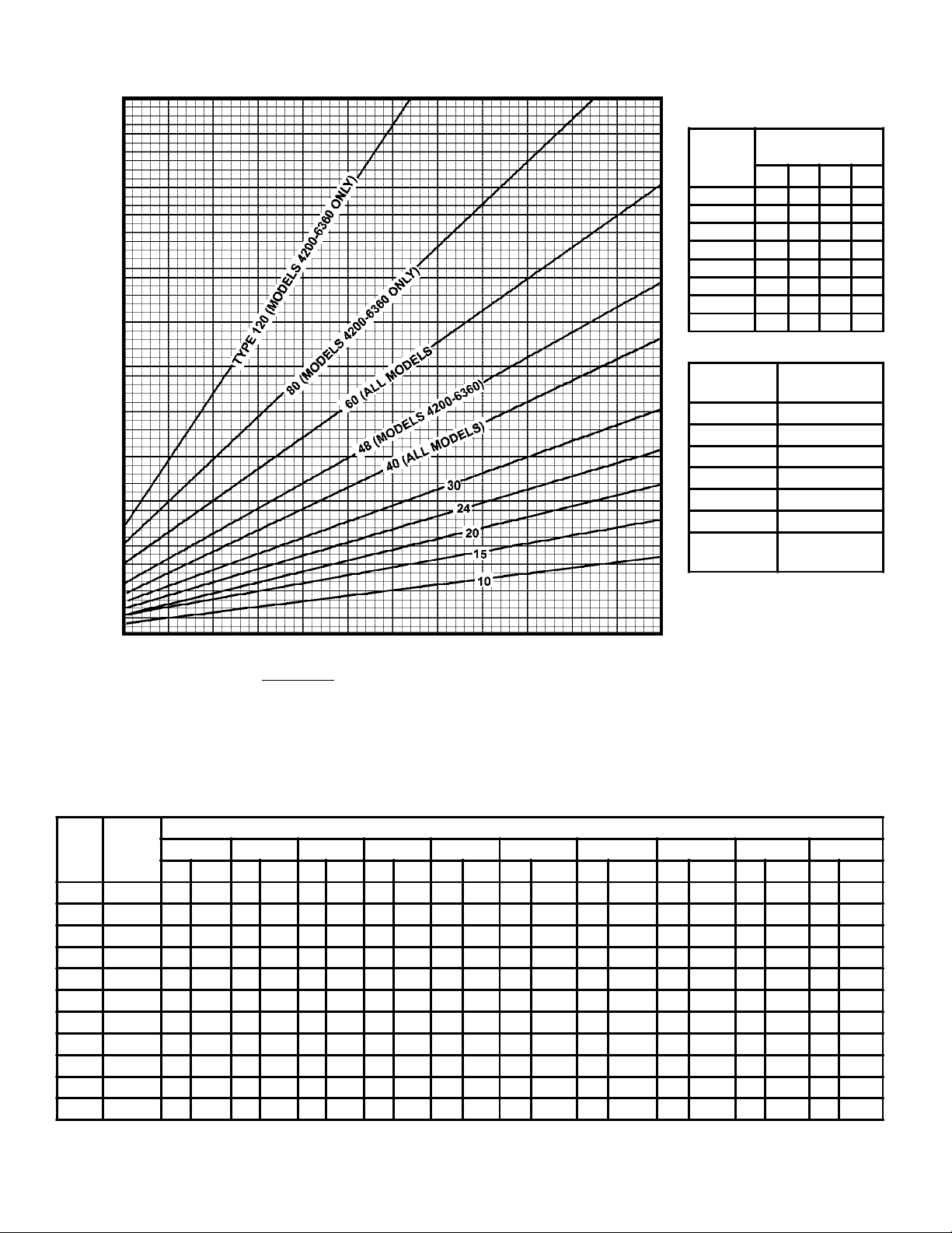
(9) Circulting requirements
Refer to Chart 1 at 50 G.P.M., Type.30 circuiting will
provide a velocity of 2.83 ft./sec. This is close to the
required minimum velocity of 2.9 ft./sec. and may be
used. (See note 2 Chart 1 for minimum velocity range).
(10) Determining Fluid Pressure Drop
Knowing the circuiting to be used, the fluid pressure
drop can be determined as follows:
(a) Find the Total Equivalent Length of tube circuit
from Table 5. For a model KDF 3152, using type
30 circuiting, the T.E.L. is 51 feet.
(b) From Table 6, note the pressure drop under 50%
solution at 2.9 ft./sec. as 060 P.S. 1. per foot of
equivalent length.
(c) Total pressure drop, P.S.I. = Pressure drop per
foot (b) multiplied by 51 feet T.E.L. (a) plus
standard allowance of 2 P.S. I. for headers:
.060 x 51 = 3.06 P. S. I.
Headers = 2.00 P. S. I.
5.06 P. S. 1.
Apply temperature correction factor from Table 7
= .9 7 x 5.06 = 4.90 P. S. I.
(11) Final Selection
1 - KeepRite KDF fluid cooler model 3152 using type 30
circuiting, having a fluid pressure drop of 4.90 P.S.I.
connections will be same end (Table 5).
Headers and connection sizes will be 2 1/8" O.D.
(Table 8).
(7) Check air quantity
A Model 3152 is rated at 21150 CFM. This
exceeds the minimum of 5688 CFM (step 2) and
is satisfactory. (See Table 1A for CFM
capacities).
(8) Determine minimum fluid velocity required
From Table 3 for a 50% glycol solution at an
average temperature of 110°F (43°C), the
required basic velocity is 3.1 ft./second.
- 3 -
“N” FACTORS
Table 2
AVE. FACTOR "N"
FLUID % GLYCOL SOLUTION
TEMP. 30% 40% 50% 60%
50 466 437 420 394
70 467 442 426 400
100 469 446 432 408
120 470 448 436 411
130 470 450 438 414
140 470 452 439 416
150 470 452 440 418
Page 4
250
200
Chart 1
TUBE CIRCUITING
BASIC
FLUID VELOCITY
Table 3
AV.
FLUID
TEMP°
50 2.9 3.7 4.6 5.8
70 2.5 3.1 3.9 5.0
100 2.0 2.6 3.2 4.2
110 2.0 2.5 3.1 4.0
120 2.0 2.4 3.0 3.8
130 2.0 2.3 2.8 3.6
140 2.0 2.2 2.7 3.4
150 2.0 2.0 2.6 3.3
GLYCOL
SOLUTION %
30 40 50 60
150
100
U.S. GALLONS / MINUTE
50
1 2 3 4 5 6
NOTES: 1. For more accurate readings use the following formula
Fluid VEL Ft./sec. =
2. When selecting circuiting, the velocity obtained can be lower than the desired velocity by not
more than 5%. A greater difference will require an alternate circuit type to be selected.
Velocities higher than the desired velocity are acceptable.
GPM x 1.70
Circuit Type
COIL AREA
RATIO
.85 1.30
.90 1.20
.95 1.10
1.00 1.00
1.10 .90
1.20 .80
1.30 and
over
* When VEL correction factor is
applied to basic fluid velocity
maximum velocity should not
exceed 6 ft./sec. Minimum should
not exceed 2 ft./sec.
VEL.* CORR.
FACTOR
.70
LENGTH OF TUBE CIRCUIT
Table 5
Table 4
Circuit
† 1052-3180 - Opposite End 4200-6360 - Same End
Header
Location
120 SE NA NA NA NA NA NA NA NA NA NA NA NA 20 6.10 23 7.02 27 8.24 31 9.46
80 OE NA NA NA NA NA NA NA NA NA NA NA NA 29 8.85 33 10.07 39 11.90 44 13.42
60 SE 14 4.27 15 4.58 20 6.10 23 7.02 27 8.24 31 9.46 38 11.59 42 12.81 51 15.56 58 17.69
48 OE NA NA NA NA NA NA NA NA NA NA NA NA 46 14.03 52 15.86 63 19.22 72 21.96
40 † 19 5.80 21 6.41 29 8.85 33 10.07 39 11.90 44 13.42 55 16.78 62 18.91 75 22.88 86 26.23
30 SE 24 7.32 27 8.24 38 11.59 42 12.81 51 15.56 58 17.69 72 21.96 82 25.01 99 30.20 113 34.47
24 † 30 9.15 33 10.07 46 14.03 52 15.86 63 19.22 72 21.96 90 27.45 101 30.81 123 37.52 141 43.01
20 SE 37 11.29 39 11.90 55 16.78 62 18.91 75 22.88 86 26.23 107 32.64 121 36.91 147 44.84 168 51.24
15 SE 46 14.03 50 15.25 72 21.96 82 25.01 99 30.20 113 34.47 142 43.31 160 48.80 195 59.48 223 68.02
10 SE 67 20.44 74 22.57 107 32.64 121 36.91 147 44.84 168 51.24 211 64.36 239 72.90 291 88.76 333 101.57
5 SE 131 39.95 145 44.23 211 64.36 239 72.90 291 88.76 333 101.57 419 127.80 475 144.88 579 176.60 663 202.22
1052 1060 2100 2120 3152 3180 4200 4240 6300 6360
FT. M FT. M FT. M FT. M FT. M FT. M FT. M FT. M FT. M FT. M
EQUIVILANT LENGTH OF TUBE CIRCUIT
- 4 -
Page 5

TUBE PRESSURE LOSS**
Table 6
FLUID PRESS. LOSS PSI/FT. T.E.L.
VEL. F/S 30% 40% 50% 60%
2.0 .028 .029 .032 .034
2.2 .036 .050 .041 .044
2.5 .042 .044 .048 .051
2.7 .048 .050 .055 .059
3.0 .055 .058 .063 .067
3.2 .064 .069 .074 .079
3.5 .072 .077 .083 .089
3.7 .080 .085 .092 .098
4.0 .090 .097 .104 .111
4.2 .100 .107 .115 .123
4.5 .110 .117 .126 .135
4.7 .122 .130 .140 .150
5.0
5.2 .164 .175 .189 .202
5.5 .183 .195 .210 .225
5.7
6.0 .231 .247 .266 .285
.140 .149 .161 .172
.207 .221 .238 .255
Where to Use Direct Drive Fluid Coolers
COMPUTER COOLING SECONDARY
HEAT EXCHANGERS
The KeepRite direct drive cooler is suitable for use with
computer room process cooling units. (See Fig. 1).
PRESSURE DROP TEMPERATURE
CORRECTION FACTORS
Table 7
GLYCOL AVG. FLUID TEMP. °F.
SOLUTION 50 70 100 110 120 130 140 150
30% 1.25 1.00 .87 .84 .82 .79 .77 .74
40% 1.27 1.10 .93 .90 .87 .84 .82 .79
50% 1.30 1.20 1.00 .97 .94 .90 .88 .85
60% 1.40 1.25 1.09 1.05 1.01 .97 .94 .90
** Based on Ave. Fluid Temp of 100°FD. Apply correction factor from
table 7.
Particularly suitable for applications where long runs of
refrigerant piping to an air cooled condenser are not practical.
Eliminates the maintenance required with cooling towers and
problems of winter operation. Piping can be easily installed
and low ambient control can be obtained by using water
regulating valves. Can be easily connected to city water for
emergency use.
REMOTE RADIATORS FOR DIESEL AND GAS ENGINES
A remote radiator is usually required with the larger style of
diesel or gas engine. The KeepRite K.D.F. direct drive cooler is
suitable for this type of application. Designed to give the
customer trouble free operation, the multiple fan arrangement
reduces the possibility of down time. Units are completely
pre-assembled and require only piping and electrical
connections. Flexible circuiting permits low fluid pressure
drop characteristics. (See Figure 2.)
INDUSTRIAL WATER COOLING*
The problem of water conservation and pollution has become
critical in recent years. The “Once-only” use of water for
industrial cooling purposes has been wasteful and often
unnecessary. By using a KeepRite dry type cooler, water for
industrial cooling applications can be cooled to within 10°F
(6°C) of the ambient dry bulb temperature. The water is
continuously recirculated and remains in a closed system so
reducing the corrosion problem normally encountered in non
recirculated systems. (See Fig. 3)
Considerable savings can be affected by using a KeepRite dry
type cooler. Many industries have reduced water
consumption by millions of gallons and reduced
maintenance costs to a fraction of that experienced prior to
using a closed recircuiation system.
*For water cooling consult your local KeepRite sales office.
- 5 -
Page 6

DIMENSIONS DATA
NOTE: Headers can be located at either end of unit.
Whether both supply and return headers are located same end or opposite end depends on coil rows and circuiting used.
KDF
MODEL
No.
1039
1052
1060
1075
2075
2100
2120
2150
3114
3152
3180
3225
4150
4200
4240
4300
6225
6300
6360
6450
A B C D
Inches mm Inches mm Inches mm Inches mm Pounds kg
43
1092
43
50
50
83 1/8
83 1/8
97 1/8
97 1/8
123 1/4
123 1/4
144 1/4
144 1/4
83 1/8
83 1/8
97 1/8
97 1/8
123 1/4
123 1/4
144 1/4
144 1/4
1092
1270
1270
2111
2111
2467
2467
3131
3131
3664
3664
2111
2111
2467
2467
3131
3131
3664
3664
48 1/8
48 1/8
48 1/8
48 1/8
48 1/8
48 1/8
48 1/8
48 1/8
48 1/8
48 1/8
48 1/8
48 1/8
93 1/8
93 1/8
93 1/8
93 1/8
93 1/8
93 1/8
93 1/8
93 1/8
1222
1222
1222
1222
1222
1222
1222
1222
1222
1222
1222
1222
2365
2365
2365
2365
2365
2365
2365
2365
36
36
43
43
76 1/8
76 1/8
90 1/8
90 1/8
116 1/4
116 1/4
137 1/4
137 1/4
76 1/8
76 1/8
90 1/8
90 1/8
116 1/4
116 1/4
137 1/4
137 1/4
914
914
1092
1092
1934
1934
2289
2289
2953
2953
3483
3483
1934
1934
2289
2289
2953
2953
3483
3483
41 1/8
41 1/8
41 1/8
41 1/8
41 1/8
41 1/8
41 1/8
41 1/8
41 1/8
41 1/8
41 1/8
41 1/8
86 1/8
86 1/8
86 1/8
86 1/8
86 1/8
86 1/8
86 1/8
86 1/8
INTERNAL VOLUME
U.S. *
GALLONS
WATER
1045
1045
1045
1045
1045
1045
1045
1045
1045
1045
1045
1045
2188
2188
2188
2188
2188
2188
2188
2188
3 1/2
4 1/2
5 1/2
6 1/2
6
8
10
12
9
12
14 1/2
18
12 1/2
16 1/2
19 1/2
24
18
24
29
36
LITRES* No.
109.8
136.3
13.3
17.0
20.8
24.6
22.7
30.3
37.9
45.4
34.0
45.4
54.9
68.1
47.3
62.3
73.8
91.0
68.1
91.0
NUMBER
OF FACE
TUBE
ROWS
30
30
30
30
30
30
30
30
30
30
30
30
60
60
60
60
60
60
60
60
FAN DATA
1
1
1
1
2
2
2
2
3
3
3
3
4
4
4
4
6
6
6
6
TOTAL
CFM
7370
7050
7380
7150
14740
14100
14760
14300
22110
21150
22140
21450
29480
28200
29520
28600
44220
42300
44280
42900
TOTAL
M3/S
3.48
3.33
3.48
3.37
6.96
6.65
6.97
6.75
10.43
9.98
10.45
10.12
13.91
13.31
13.93
13.5
20.87
19.96
20.9
20.25
SHIPPING
WEIGHT
320
355
390
430
580
645
725
800
870
965
1080
1200
1075
1200
1340
1500
1600
1850
2000
2200
145
161
177
195
263
293
329
363
395
438
490
544
488
544
608
680
726
839
907
998
* Headers not included. Motors are available for 208-230/1/60 - 1 HP, 208-230/3/60 - 1 1/3 HP, 575/3/60 - 1 1/4 HP.
Contact KeepRite Refrigeration for special requirements NOTE: Metric figures are approximate to avoid excessive decimals.
OPTIONAL FACTORY SUPPLIED FLANGES
SIZE
(mm)
3"
(76.2)
4"
(101.6)
5"
(127.0)
6"
(152.4)
FITTING
Flanged
Flanged
Flanged
Flanged
FLANGE
DIA. (mm)
7 1/2"
(190.5)6"(152.4)
9"
(228.6)
10"
(254.0)
11"
(279.4)
BOLT
CIRCLE
(mm)
7 1/2"
(190.5)
8 1/2"
(215.9)
9 1/2"
(241.3)
HOLES
(mm)
4-3/4"
(19.05)
8-3/4"
(19.05)
8-7/8"
(22.2)
8-7/8"
(22.2)
OPTIONAL FLANGED CONNECTIONS
BOLT HOLE LOCATION
(150 lbs. working shock pressure)
- 6 -
Page 7

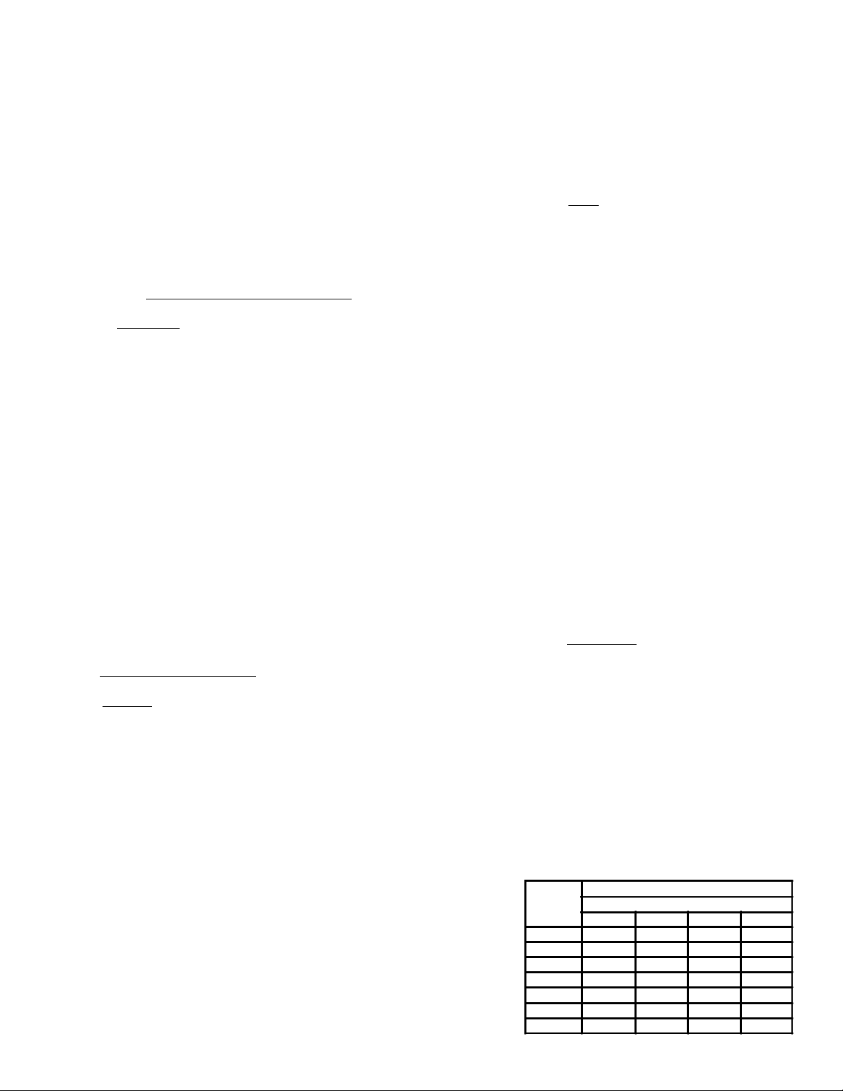
FIG 1
INSPECTION
INSTALLATION INSTRUCTIONS
LOCATION
In selecting a location for the cooler, consideration
should be given to the following:
(a) Loading capacity of the floor or roof.
(b) Distance to suitable electrical supply.
(c) Adequate air circulation.
(d) Accessibility for maintenance.
(e) Local building codes.
(f) Adjacent buildings relative to noise levels.
(g) Wishes of the purchaser.
When all of the above points have been considered
and a specific location chosen, it is advisable to
obtain written approval of this location from the
building and/or cooling unit owner. This may be the
means of avoiding disagreement and expense at a
later date.
GENERAL CHECK-UP BEFORE STARTING
(1) Check the electrical characteristics of all
components to be sure they agree with the power
supply.
(2) Check fans for correct rotation on 3 phase units.
Air is drawn through the cooler core. To change
direction of rotation reverse any two (2) connecting
leads.
A thorough inspection of the cooler and all component
parts should be made immediately on delivery and any
camage in transit or any missing parts must be reported
at once to the carrier, As consignee, you must make any
claim for damage or losses. Damaged or missing parts
discovered at the outset can prevent later costly delays
and unnecessary expense. Electrical characteristics of
all motors should also be checked to ensure that they are
as ordered.
WARNING
ADEQUATE PRECAUTIONS MUST BE TAKEN, AFTER
FIELD LEAK TESTING, TO INSURE REMOVAL OF
WATER IN TUBES. KEEPRITE RECOMMEND THAT
A GLYCOL SOLUTION BE USED TO FLUSH THE
COMPLETE COIL. FAILURE TO TAKE PRECAUTIONS
CAN RESULT IN FROZEN TUBES SHOULD UNIT BE
SUBJECTED TO LOW AMBIENT CONDITIONS
BEFORE BEING PLACED IN OPERATION.
HANDLING AND PLACING
Air Cooled Fluid Coolers are by necessity large and heavy
pieces of mechanical equipment and must be handled as
such. A fully qualified and properly equipped crew with
necessary tackle and rigging should be engaged to locate
the unit in position.
Lifting brackets have been provided at the corners for
attaching lifting slings. Spreader bars or a similar device
must be used when lifting so that the lifting force will be
applied vertically on the lifting brackets. (See Fig. 1).
Important:
Units with solid state speed control option are for
use with 208-230/1/60 service only.
SERVICE INSTRUCTION
Casing
Since the Fluid Cooler is normally installed outdoors, in
the elements, the casing is fabricated from heavy gauge
continuous process galvanized sheet steel for maximum
rust and corrosion protection.
Motors
Motors are split capacitor type and are permanently
lubricated.
Coil
The coil should be checked periodically for cleanliness
and for leaks. It is important that the coil be kept clean
and free from any type of air blockage. The coil may be
washed down with a hose when dirty. Power must be
disconnected for this operation.
HEADER SIZING
Table 8
G.P.M.
0 - 10
11 - 20
21 - 30
31 - 50
51 - 80
81 - 150
151 - 250
251 - 400
400 - 700
Header Size
O.D.
1 1/8 (29mm)
1 3/8 (35mm)
1 5/8 (41mm)
2 1/8 (54mm)
2 5/8 (67mm)
3 1/8 (79mm)
4 1/8 (105mm)
5 1/8 (130mm)
6 1/8 (156mm)
Connections
Available
PLAIN
or
MPT
PLAIN
or
FLANGED
- 7 -
Page 8

PIPING INSTALLATION
1. All piping must comply with local codes. Care
should be taken to correctly size the piping to
ensure minimum pumping costs.
2. Sufficient valves and unions should be provided to
permit easy removal of equipment for repair or
replacement.
3. All piping should be leak tested after installation.
4. Where city water is required for make-up, local
plumbing codes should be observed. A pressure
reducing valve should not be used in glycol
systems. Installation of same would dilute the
mixture in the case of a leak.
5. Piping system must be complete with an
expansion tank, purge valve, relief valve and fill
point for glycol. Vent valves should be provided at
system high points for air removal. See fig. 2 for
typical glycol system piping.
CIRCULATING PUMP
Mechanical seal type circulating pumps are generally
used for glycol systems. Pump must be selected for
friction loss through the cooler, piping and heat source.
In a closed system no allowance is required for vertical
lift.
Parallel pumps are recommended for standby operation
where pump failure may interfere with a critical process.
One pump on a parallel system may also carry the load
under certain conditions thus contributing to power
economy.
GLYCOL DESIGN
Usually a glycol solution is used in fluid cooler
applications. The common range of mixtures will be 30%
to 50% in water. Glycol mixtures have a higher density
than water , but a lower specific heat. This will result in an
increased flow rate over water by approx. 15% - 20%.
Where a fluid cooler is used with an existing water cooled
condenser, a decrease in condenser capacity will result.
Condenser manufacturers should be consulted to obtain
recommended flow rates.
MAINTAINING THE SYSTEM
As the system is the closed type with a compression
tank, little or no corrosion will take place as the initial
oxygen is absorbed. No fresh oxygen is introduced unless
the system requires re-filling due to leaks or repairs.
Maintenance of the system will therefore be confined to
the pumps and valves. Manufacturers data should be
consulted for the maintenance of these items.
Figure 2
TYPICAL FLUID COOLER PIPING SYSTEM
- 8 -
Page 9

- 9 -
Page 10

- 10 -
Page 11

- 11 -
Page 12

DESIGN SPECIFICA TIONS
03/15/2007
CASING
Heavy gauge galvanized steel with zinc plated nuts and
bolts. All KeepRite Fluid Coolers are mounted on heavy
die-formed legs.
COILS
The KeepRite Direct Drive Fluid Cooler is equipped with
high-efficiency heat transfer surface. Surface consists of
rippled aluminum fins hydraulically bonded to copper
tubing. Coils are leak tested to 300 p.s.i. under water.
Flanged connections available if required.
SERVICE LOG
ETADSTNEMMOC
FANS
Four-bladed, constructed from heavy gauge, rustresistant aluminum with steel spider and hub. Zinc
plated for added weather protection.
MOTORS
Direct drive fan motors with permanently lubricated ball
bearings. Motors are complete with inherent overload
protection. Motors are weather protected by top end rain
shields and shaft moisture slingers. Contactors available if required. Motors are all wired to an electrical box
on end of unit.
PROJECT INFORMA TION
metsyS
rebmuNledoM pU-tratSfoetaD
rebmuNlaireS rotcartnoCecivreS
tnaregirfeRenohP
ylppuSlacirtcelExaF
NA TIONAL REFRIGERA TION &
AIR CONDITIONING CANADA CORP.
CANADA
159 ROY BL VD., BRANTFORD, ONT ARIO, CANADA N3R 7K1
PHONE: 1-800-463-9517 (519)751-0444 FAX (519)753-1140
USA
985 WHEELER WA Y, LANGHORNE, P A. 19047 USA
PHONE:1-888-KEEPUS1 OR 1-888-533-7871
Due to National Refrigeration’s policy of continuous product improvement, we reserve the right to make changes without notice.
 Loading...