

Page 1
PRODUCT DATA &
INSTALLATION
Bulletin K50-KCC-PDI-10
1064435
We are on the Internet
www.keepriterefrigeration.com
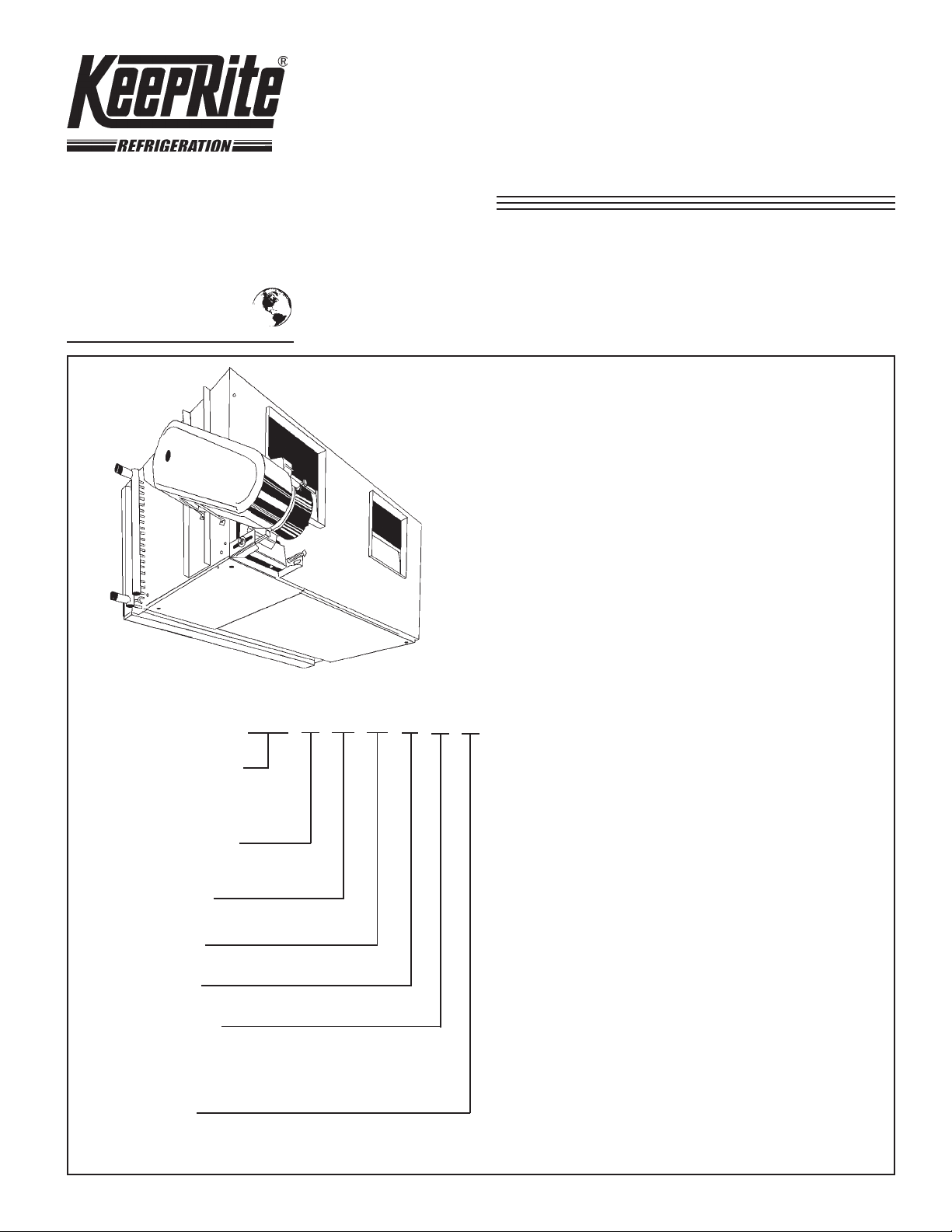
KCC Centrifugal
Fan Air Cooled
Condensers
Air Cooled Models from 103 Thru 164
Four to ninety Ton
• Galvanized steel, angular steel frame cabinet
construction
• Removable access panels
• Galvanized steel fan housings and wheels.
• 12” (305mm) diameter fan wheels keyed to fan
NOMENCLATURE
KCC 1 12 19 4 A D
CENTRIFUGAL F AN
AIR COOLED
CONDENSER
NUMBER OF FANS
1 OR 2
NOMINAL COIL
FACE AREA
FIN SPACING
ROW DEPTH
shaft
• Direct drive fan motors with inherent overload
protection.
• Weather protected motors with top end rain
shields and shaft moisture slingers.
• High efficiency rippled aluminum fin coils
• Adjustable motor bases and drives
CONTENTS
Nomenclature.........................................
Capacity Data.........................................
Fan Data..................................................
Selection Data........................................
Dimensional Data...................................
Installation Instructions.........................
PAGE
Cover
5,6
7,8
2
2
3
FIN THICKNESS
A = .0055
C = .0075
C = .009
FAN MOTOR
AND DRIVE
Design Specifications............................
Service Log.............................................
Project Information................................
9
Back
Back
Page 2
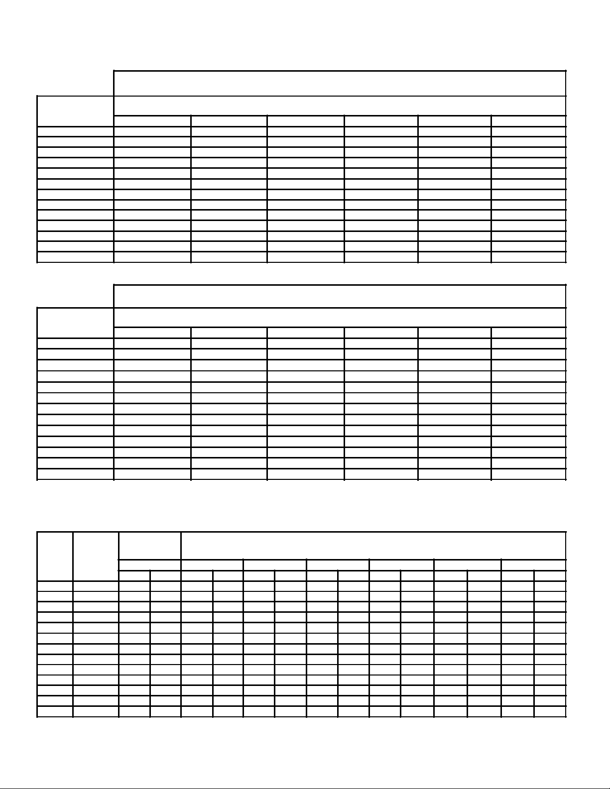
CAPACITY DATA
TABLE 2
KCC
MODEL NO.
103 1800 18000 27000 36000 45000 54000
104 2730 27300 41000 54600 68300 82000
106 3900 39000 58500 78000 97500 117000
108 5200 52000 78000 104000 130000 156000
111 6930 69300 104000 138600 173300 208000
214 8860 88600 133000 177300 221600 266000
217 10500 105000 157500 210000 262500 315000
222 13030 130300 195500 260600 325800 391000
228 16360 163600 245500 327300 409100 491000
237 21460 214600 321900 429200 536600 643800
141 25200 252000 378000 504000 630000 756000
150 28980 289800 434700 579600 724500 869400
164 36580 365800 548700 731600 914500 1097400
TABLE 2
KCC
MODEL NO.
103 1750 17500 26250 35000 43750 52500
104
106
108
111 6720 67900 100800 134400 168000 201600
214 8590 85900 128850 171800 214750 257700
217
222
228
237 20820 208200 312300 416400 520500 624600
141 24440 244400 366600 488800 611000 733200
150
164
R-22 TOTAL HEAT REJECTION (BTU/HR)
°F. (°C) TEMPERATURE DIFFERENCE = CONDENSING TEMPERATURE MINUS AMBIENT TEMPERATURE
1 (.6) 10 (6) 15 (8) 20 (11) 25 (14) 30 (17)
R-404A TOTAL HEAT REJECTION (BTU/HR)
°F. (°C) TEMPERATURE DIFFERENCE = CONDENSING TEMPERATURE MINUS AMBIENT TEMPERATURE
1 (.6) 10 (6) 15 (8) 20 (11) 25 (14) 30 (17)
2650 26500 39750 53000 66250 79500
3780 37800 56700 75600 94500 113400
5040 50400 75600 100800 126000 151200
10190 101900 152850 203800 254750 305700
12640 126400 189600 252800 316000 379200
15870 158700 238050 317400 396750 476100
28110 281100 421650 562200 702750 843300
35480 354800 532200 709600 887000 1064400
FAN DATA
TABLE 3
STANDARD
MODEL
NOMINAL
NO.
103 2000
104 3150 810 1.16 870 1.25 930 1.37 1007 1.49 1075 1.57 1136 1.66 1195 1.98
106 4500 910 1.76 948 1.89 996 2.06 1045 2.25 1096 2.44 1148 2.65 1202 2.87
108 6000 680 2.00 716 2.15 765 2.42 813 2.71 863 3.02 911 3.33 960 3.66
111 8000
214 10000
217 12000
222 15000
228 19000 505 6.15 533 6.79 573 7.68 613 8.61 653 9.60 691 10.62 729 11.68
237 23000 447 7.22 473 7.88 511 8.97 547 10.10 584 11.27 619 12.47 653 13.70
141 29000 338 10.55 355 11.73 370 13.14 397 14.53 420 15.92 442 17.28 463 18.68
150 34000 285 11.17 301 12.39 326 1.398 350 15.57 372 17.20 393 18.85 413 20.55
164 42000
C.F.M.
6 ROW COIL
ONLY
.55 .75 1.00 1.25 1.50 1.75 2.00
R.P.M. B.H.P. R.P.M. B.H.P. R.P.M. B.H.P. R.P.M. B.H.P. R.P.M. B.H.P. R.P.M. B.H.P. R.P.M. B.H.P.
1077 0.65 1167 0.72 1272 0.81 1371 0.91 1465 1.01 1555 1.12 1644 1.23
658 3.05 691 3.28 727 3.60 767 3.95 808 4.35 850 4.78 894 5.23
800 3.63 842 3.98 900 4.40 956 4.84 1012 5.30 1066 5.77 1120 6.27
706 4.15 744 4.54 795 5.05 846 5.59 897 6.15 948 6.74 998 7.36
655 5.42 689 5.89 734 6.53 780 7.20 825 7.91 869 8.64 913 9.40
263 14.58 279 16.03 300 18.12 321 20.18 340 22.20 363 24.24 376 26.27
TOTAL STATIC PRESSURE (Includes Coil, Ductwork etc.)
- 2 -
Page 3
SELECTION DATA
The selection of an air cooled condenser is based on the
heat rejection capacity at the condenser rather than net
refrigeration effect at the evaporator because the refrigerant gas absorbs additional energy in the
compressor. This additional energy, the heat of
compression, varies appreciably with the operating
conditions of the system and with compressor design,
whether open or suction cooled hermetic type.
Some compressor manufacturers publish heat rejection
figures as part of their compressor ratings. Since heat
rejection varies with compressor design, it is
recommended that the compressor manufacturer’s data
be used whenever available in selecting an air cooled
condenser.
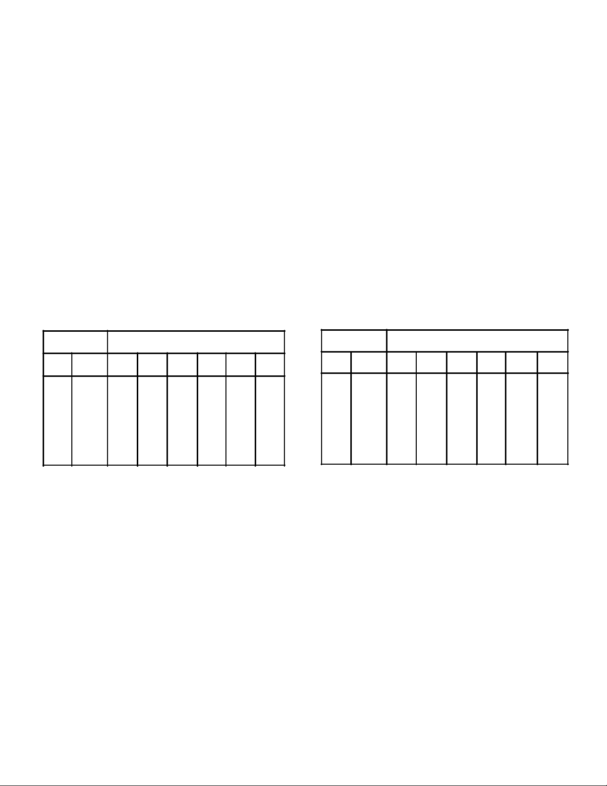
HEAT REJECTION FACTORS
CONDENSER LOAD = COMPRESSOR CAPACITY X FACTOR
OPEN COMPRESSORS
TABLE NO. 4
EVAPORATOR
TEMP
°F. °C.
-30
-20
-10
10
20
30
40
50
-34
-29
-23
0
-18
-12
-7
-1
4
10
* Outside of normal limits for single stage compressor application.
For two stage application use formulas above.
CONDENSING TEMPERATURE °F. (°C.)
90
(32)
1.37
1.33
1.28
1.24
1.21
1.17
1.14
1.12
1.09
100
(38)
1.42
1.37
1.32
1.28
1.24
1.20
1.17
1.15
1.12
110
(43)
1.47
1.42
1.37
1.32
1.28
1.24
1.20
1.17
1.14
120
(49)
*
1.47
1.42
1.37
1.32
1.28
1.24
1.20
1.17
130
(54)
*
*
1.47
1.41
1.36
1.32
1.27
1.23
1.20
140
(60)
1.47
1.42
1.37
1.32
1.28
1.24
*
*
*
If thecompressor manufacturer does not publish heat
rejection ratings, factors from Table Nos. 4 and 5 may be
used to estimate total heat rejection-THR.
For systems outside the normal limits of single stage
compressor application, (such as compound or cascade
refrigeration systems) the following formulas may be
used to arrive at the heat rejection requirements for
selection of the condenser:
Open Compressors
THR = Compressor Capacity (Btuh) + 2545 x Bhp
Suction Cooled Hermetic Compressors
THR = Compressor Capacity (Btuh) + 3413 x KW
SUCTION COOLED HERMETIC COMPRESSORS
TABLE NO. 5
EVAPORATOR
TEMP
°F. °C. 90 (32)
-30
-20
-10
10
20
30
40
50
-34
-29
-23
0
-18
-12
-7
-1
4
10
* Outside of normal limits for single stage compressor application.
For two stage application use formulas above.
CONDENSING TEMPERATURE °F. (°C.)
1.57
1.49
1.42
1.36
1.31
1.26
1.22
1.18
1.14
100
(38)
1.62
1.53
1.46
1.40
1.34
1.29
1.25
1.21
1.17
110
(43)
1.68
1.58
1.50
1.44
1.38
1.33
1.28
1.24
1.20
120
(49)
*
1.65
1.57
1.50
1.43
1.37
1.32
1.27
1.23
130
(54)
1.64
1.56
1.49
1.43
1.37
1.31
1.26
140
(60)
*
*
*
*
*
1.62
1.55
1.49
1.42
1.35
1.29
SELECTION EXAMPLE
GIVEN:
Compressor Capacity 350,000 Btuh
Evaporator Temperature 40°F.
Refrigerant R-22
Ambient Air 95°F.
Maximum Condensing Temperature 120°F.
Suction Cooled Hermetic Compressor
PROCEDURE:
(1) Assuming the compressor manufacturer’s heat
rerejection data is not available, determine the
heat rejection factors for the specified conditions
from Table No. 5 above (1.27).
(2) Multiply the compressor capacity by the heat
rejection factor to estimate the required
condenser capacity.
(3) Since R-22 is specified, select the proper
condenser from Table No. 1 based on the
specified difference between condensing
refrigerant and the ambient air (T.D.).
SELECTION:
Using the heat rejection factor from Table No. 5 above,
the required condenser capacity is:
1.27 x 350.000 = 444,000 Btuh
From Table No. 1 for the specified T.D. of 25°F the proper
selection is the Model KCC 237 with a capacity of
536,600 Btuh. In this instance the condenser is slightly
oversized and the condenser will balance the
compressor heat rejection at less than the maximum
condensing temperature of 120°F.
- 3 -
Page 4
MULTIPLE COMPRESSOR APPLICATIONS
Multi-section units are available for applications where
more than one compressor is used either on the same
system or separate systems. Usually, this
arrangement will result in lower installation costs as
opposed to using separate units.
Coils for multi-section condensers are factory circuited
and divided into the proper number of sections, each sized
to meet the specified capacity. Each circuit is supplied
with a hot gas inlet and liquid outlet connection and
tagged for identification. The fan on a multi-section unit
should remain operative as long as a condensing requirement exists in any section of the coil.
TABLE 6 HEAT REJECTION CAPACITY PER FACE TUBE (BTU / HR) - R12
KCC
MODEL NO.
103 12 150 1502 2252 3003 3754 4505
104 14 194 1943 2914 3885 4856 5828
106 16 245 2447 3670 4893 6116 7340
108
111
214 22 402 4022 6032 8043 10054 12065
217 22 477 4767 7151 9534 11918 14301
222
228
237
141 40 630 6300 9450 12600 15750 18900
150 46 630 6300 94.50 12600 15750 18900
164
For R-404A ratings, multiply above capacities by 0.97.
FACE
TUBES
22 236 2363 3544 4725 5906 7088
22 315 3150 4725 6300 7875 9450
26 500 4998 7479 9996 12495 14994
26 630 6300 9450 12600 15750 18900
34 630 6300 9450 12600 15750 18900
58 626 6258 9387 12516 15646 18774
SELECTION EXAMPLE
°F. (°C) TEMPERATURE DIFFERENCE = CONDENSING TEMPERATURE MINUS AMBIENT TEMPERATURE
1 (.6) 10 (6) 15 (8) 20 (11) 25 (14) 30 (17)
GIVEN:
Six hermetic compressors with capacities and
evaporator temperatures (tabulated below).
Refrigerant R-22
Ambient Air Temperature 100°F.
Maximum Condensing Temperature 120°F.
PROCEDURE:
1. Tabulate the compressor capacities, evaporator
temperatures and heat rejection factors for each
compressor. (See Sample Tabulation, below.)
2. Determine the required heat rejection capacity for
each compressor.
3. Total the sectional heat rejection capacities for the
six compressors.
SELECTION:
Based on the total heat rejection capacity for the six
compressors of 186,160 Btuh, it can be seen from
Table No. 1 that the smallest unit which will meet this
requirement is the Model KCC217 with 210,000 Btuh
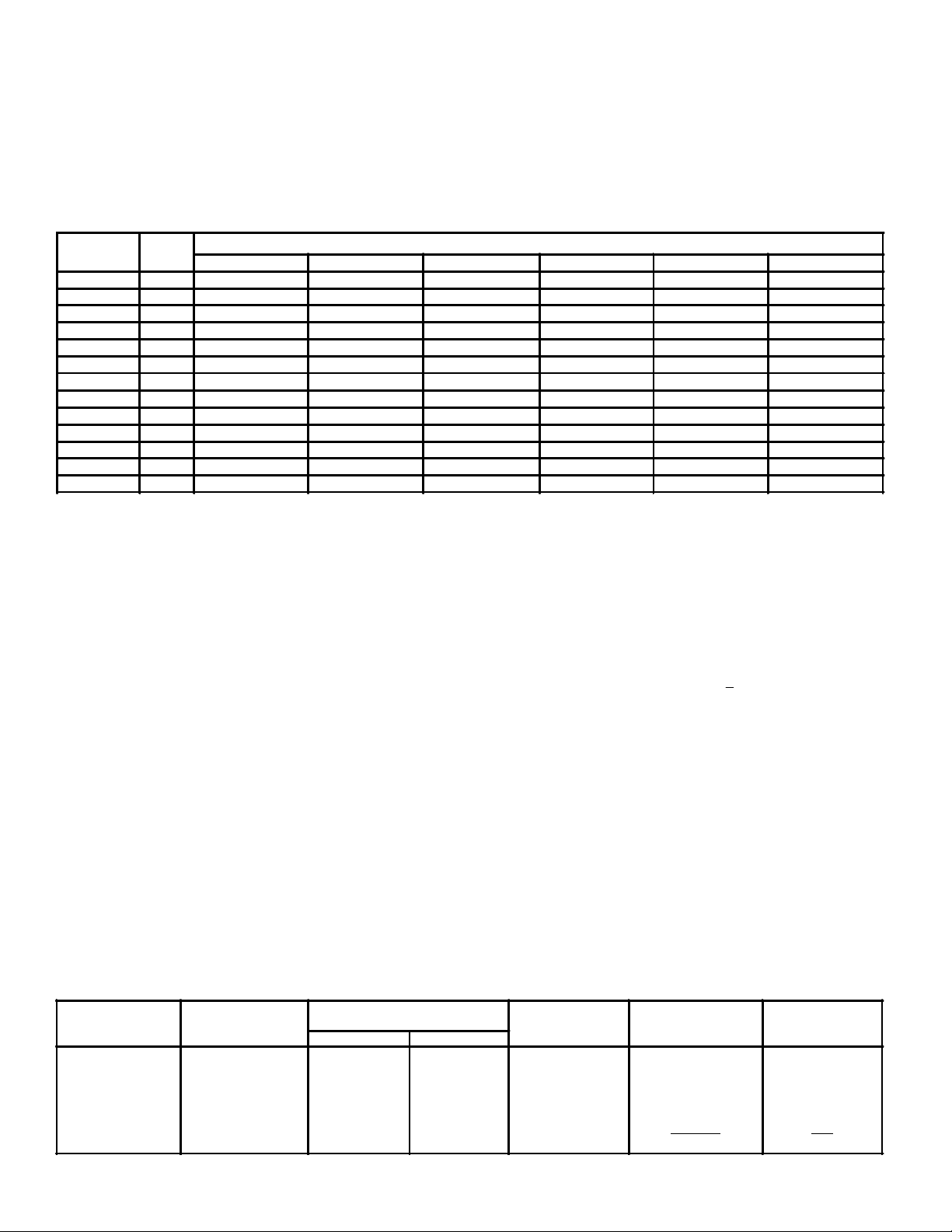
SAMPLE TABULATION
COMPRESSOR
NO.
1
2
3
4
5
6
COMPRESSOR
CAPACITY (BTUH)
13500
10000
36000
11000
31000
25000
EVAPORATOR
TEMPERATURE
°F. °C.
+20
-15
+15
+20
-10
+20
at 20 °F. T.D. Table No. 6 lists the heat rejection
capacity per “face tube” at various T.D.’s.
At 20 °F. T.D., the KCC 217 has a capacity of 9534 Btuh
per “face tube”. To determine the required number of face
tubes for each section, divide the required sectional
capacity by the capacity per “face tube”. For example,
compressor No. 1 requires 18,000 : 9534 = 2 “face tubes”.
Section No. 1 should be eircuited with 2 “face tubes” for
Compressor No. 1. Following this same procedure will
determine the size of each section for the remaining
compressors.
The sample tabulation shows the results of this selection
and indicates that 22 “face tubes” are required when
using the Model KCC 217. Since the Model KCC 217
has 22 “face tubes” available, the selection has been
satisfied. If the total required number of “face tubes”
exceeds the number of “face tubes” available as listed in
Table No. 6 it will be necessary to permit a slightly higher
condensing temperature than planned for one or two of
the sections. A second alternative would be to select the
next larger size condenser.
REQUIRED
CONDENSER
CAPACITY (BTUH)
18000
17440
51400
15070
50000
_34250_
186160
NUMBER OF
FACE TUBES
-7
-23
-9
-7
-23
-7
HEAT REJECTION
FACTOR
1.37
1.57
1.40
1.37
1.57
1.37
REQUIRED
2
2
6
2
6
_4_
22
- 4 -
Page 5

MODELS KCC103 THRU KCC223
MODELS KCC237 THRU KCC164
DIMENSIONAL DATA
DIMENSIONS - GENERAL DATA
MODEL
No.
KCC
103
104
106
108
111
214
217
222
228
237
141
150
164
A B D G H J K M N P R S T U V
ins. 34 22 3/4 21 3/4 11 3/4 10 1/4 6 1/2 11 1/8 16 1/8 - 28 1/2 1 1/2 - 15 18 30
mm
864 578 553 299 260 165 283 410 - 724 38 - 381 457 762
ins.
40 25 3/4 24 3/4 12 1/4 13 1/2 6 1/2 13 7/8 19 1/8 - 34 1/2 1 1/2 - 15 21 36
mm
1016 654 629 311 343 165 352 486 - 876 38 - 381 533 914
ins. 50 29 28 17 1/4 15 7/8 6 1/2 16 3/8 22 3/8 - 44 1/2 1 1/2 - 16 24 45
mm 1270 737 711 438 403 165 416 568 - 1130 38 - 406 610 1143
ins. 48 37 3/4 36 3/4 21 1/8 19 3/8 8 13 3/8 31 1/8 - 42 1/2 1 1/2 - 18 33 44
mm 1219 959 934 537 492 203 340 791 - 1080 38 - 457 838 1118
ins. 63 37 3/4 36 3/4 23 1/4 21 5/8 8 19 7/8 31 1/8 - 57 1/2 1 1/2 - 18 33 58
mm 1600 959 934 591 549 203 505 791 - 1461 38 - 457 838 1473
ins. 78 37 3/4 36 3/4 19 17 7/8 8 10 31 1/8 - 72 1/2 1 1/2 20 21 33 74
mm 1981 959 934 483 454 203 254 791 - 1842 38 508 533 838 1880
ins. 93 37 3/4 36 3/4 21 1/8 19 3/8 8 12 3/4 31 1/8 - 87 1/2 1 1/2 25 3/8 21 33 88
mm 2362 959 934 537 492 203 324 791 - 2223 38 645 533 838 2235
ins. 97 44 3/4 43 3/4 23 1/4 21 5/8 9 12 5/8 38 1/8 - 91 1/2 2 25 1/4 21 39 92
mm 2464 1137 1111 591 549 229 321 968 - 2324 51 641 533 991 2337
ins. 120 44 3/4 43 3/4 28 1/4 26 1/2 9 15 7/8 38 1/8 - 114 1/2 2 31 3/4 23 39 116
mm
3048 1137 1111 718 673 229 403 968 - 2908 51 807 584 991 2946
ins.
122 1/8 57 3/8 45 5/8 31 1/2 28 3/4 11 1/2 15 1/8 39 1/2 11 3/4 117 7/8 2 29 25 51 116
mm 3102 1457 1159 800 730 292 384 1003 299 2994 51 737 635 1295 2946
ins. 122 1/8 65 5/8 59 1/8 46 3/8 43 1/4 11 1/2 37 7/8 53 6 1/2 117 7/8 1 3/4 - 25 60 116
mm 3102 1667 1502 1178 1099 292 962 1346 165 2994 45 - 635 1524 2946
ins. 122 1/8 75 3/8 66 5/8 51 1/2 47 1/4 11 1/2 35 3/8 60 1/2 8 3/4 117 7/8 2 - 25 69 116
mm 3102 1915 1692 1308 1200 292 899 1537 222 2994 51 - 635 1753 2946
ins. 122 1/8 93 3/8 72 5/8 56 3/4 52 3/8 11 1/2 32 5/8 66 1/2 20 3/4 117 7/8 2 - 25 87 116
mm
3102 2372 1845 1442 1330 292 829 1689 527 2994 51 - 635 2210 2946
* For R502 multiply charge in lbs. by 0.93 and for R500 by 0.88. For winter charge, multiply by 6.65.
** For filter section dimensions refer to page 7.
- 5 -
REFRIGERANT*
No. of
FACE
TUBES
12 3.31 1.50 2.98 1.35 343 156
14 4.50 2.04 4.05 1.84 431 196
16 5.85 2.66 5.27 2.39 600 272
22 7.88 3.58 7.09 3.22 806 366
22 10.28 4.67 9.25 4.20 996 452
22 13.02 5.91 11.72 5.32 1171 531
22 14.20 6.45 12.90 5.86 1393 632
26 17.46 7.93 15.86 7.20 1714 778
26 21.55 9.78 19.59 8.89 2163 981
34 28.72 13.04 26.10 11.85 3420 1551
40 34.29 15.57 31.15 14.14 3500 1588
46 41.28 18.74 38.05 17.27 4500 2041
58 53.31 24.20 47.98 21.78 5900 2676
CHARGE
6 ROW COIL
R-12 R-22
Lbs. kg. Lbs. kg
SHIPPING
WEIGHT
Lbs. kg
Page 6

MULTIPLE CIRCUIT CONNECTION SIZES
NET TONS 0 - 7 1/2 † 8-10 11-13 14-18 19-28 29-35 36-43 44-57 58-64 65-72 73 & up
HOT GAS
INLET
LIQUID
OUTLET
ins. 1 1/8 1 3/8 1 3/8 1 5/8 2 1/8 2 1/8 2 5/8 2 5/8 3 1/8 3 1/8 3 5/8
mm 29 35 35 41 54 54 67 67 79 79 92
ins. 7/8 7/8 1 1/8 1 1/8 1 3/8 1 5/8 1 5/8 2 1/8 2 1/8 2 5/8 2 5/8
mm 22 22 29 29 35 41 41 54 54 67 67
FAN DISCHARGE ARRANGEMENTS MOTOR & ACCESS PANEL LOCATIONS
(Viewed from Drive End)
NOTE: Models 237 thru 164 only available with CU and CCU discharge arrangement when furnished with a special “square” fan cabinet.
Not available with motor location or access location on bottom.
FILTER SECTIONS
FILTER SECTIONS
UNIT
SIZE
103 34 864 21 5/8 549 28 1/2 724 16 1/2 419 30 5/8 778 17 5/8 448
104
106
108
111 63 1600 36 5/8 930 57 1/2 1461 20 1/2 521 59 5/8 1514 32 1/2 826 118 54
214 78 1981 36 5/8 930 72 1/2 1842 25 1/2 648 74 5/8 1895 32 1/2 826 26 660 74 5/8 1895 33 1/4 845 26 660 140 64 305 138
217 93 2362 36 5/8 930 87 1/2 2223 25 1/2 648 89 5/8 2276 32 1/2 826 26 660 89 5/8 2276 33 1/4 845 26 660 161 73 348 158
222 97 2464 43 5/8 1108 91 1/2 2324 16 1/2 419 93 5/8 2378 40 1/8 1019 23 584 93 5/8 2378 40 1/4 1022 23 584 189 86 377 171
228
237
141
150 119 3/8 3032 73 1/8 1857 117 7/8 2994 20 1/2 521 116 5/8 2962 70 1/8 1781 25 1/2 648 115 1/8 2934 69 3/4 1772 25 1/2 648 342 155 776 352
164 119 3/8 3032 91 1/8 2314 117 7/8 2994 20 1/2 521 116 5/8 2962 85 1/4 2165 27 1/8 689 115 1/8 2934 87 3/4 2229 27 1/8 689 416 189 903 410
A B P
T U V T U V Y Flat Angular
ins mm ins mm ins mm ins mm ins mm ins mm ins mm ins mm ins mm ins mm lb kg lb kg
40 1016 24 5/8 626 34 1/2 876 20 1/2 521 36 5/8 930 20 508 49 22
50 1270 27 7/8 708 44 1/2 1130 16 1/2 419 45 5/8 1184 23 1/8 587 62 28
48 1219 36 5/8 930 42 1/2 1080 25 1/2 648 44 5/8 1133 32 1/2 826 86 39
120 3048 43 5/8 1108 114 1/2 2908 20 1/2 521 116 5/8 2962 40 1/8 1019 23 584 116 5/8 2962 40 1/4 1022 23 584 232 105 449 204
119 3/8 3032 55 1/8 1400 117 7/8 2994 20 1/2 521 116 5/8 2962 50 1/8 1273 25 1/2 648 115 1/8 2934 51 3/4 1314 22 1/4 565 278 126 675 283
119 3/8 3032 63 3/8 1610 117 7/8 2994 20 1/2 521 116 5/8 2962 60 1/8 1527 21 1/8 536 115 1/8 2934 60 1524 21 1/8 536 303 137 656 298
FLAT ANGULAR
NA NA NA NA NA NA NA NA
SHIPPING
WEIGHTS
39 18
NA NA
- 6 -
Page 7

IMPORTAN THE FOLLOWING KEEPRITE REFRIGERATION CENTRIFUGAL FAN UNITS MUST BE
GENERAL
INSTALLATION INSTRUCTIONS
PLATFORM OR FLOOR MOUNTED
CONDENSERS KCC237, KCC141, KCC150, KCC164
Unit should be carefully checked for damage when
received. Visible or concealed damage should be
reported immediately to the carrier and a claim
filed.
All KCC Centrifugal condensers are inspected
thoroughly before shipment. However, fans and
shaft should be inspected before installation to
insure that misalignment has not happened in
shipment or handling. For long and trouble free
life, the units should have proper care and
maintenance.
Units should be located so that enough space is left
around the unit for lubrication, belt adjustment and
coil removal if necessary.
For units with free air intake and discharge, care
should be taken to insure that there are no
obstructions that will interfere with the air flow.
DRIVE INSTALLATION
Smaller motors are usually shipped mounted on the
unit. Larger motors will be shipped separately.
When motors are shipped separately the mounting
procedure should be as follows:
(a) Bolt motor to the motor base on the unit.
(b) If not already mounted, install fan motor
sheaves.
(c) Align sheaves with straight edge to insure true
running belts.
(d) Adjust motor mount for proper belt tension.
(e) Attach belt guard to end panel of blower
section.
MOUNTING UNITS
Smaller models may be floor mounted or ceiling
hung. Larger models may be floor mounted only.
When hoisting units, a spreader bar should be
used to prevent damage to the casing. Units are
equipped with 518 “ (16 mm) N.C. tapped hanger
nuts or 3/4 “ (19 mm) anchor holes for floor
mounting.
DUCTWORK
Where ductwork is to be used with units,
connection to unit should be
made with flexible canvas sleeves.
MAINTENANCE BEFORE START UP
(a) Check tightness of all bearing, sheave and
fan wheel set screws.
(b) If fan wheel set screws are loose, check to
insure that Wheel is not rubbing in housing.
(c) Leak-lest system to make sure that all joints
are tight.
(d) Ball bearings are pre-lubricated and require
no further lubrication at start-up.
(e) Rotate shaft by hand to make sure it runs
freely.
(f) Check fan and motor for correct rotation. If
running the wrong direction, reverse phases
at motor. Re-check rotation.
(g) Check drive alignment and belt tension.
- 7 -
Page 8

AFTER FIRST 48 HOURS
1. Check all previous points under ”Before
Start-Up”.
2. Belts will have stretched. Re-check tension
and adjust motor where necessary.
PERIODIC SERVICE & MAINTENANCE
(a) Check all moving parts for wear every 6
months.
(b) Check bearing collar set screws for
tightness every 6 months.
(c) Check belt tension and adjust if necessary.
MOTOR BEARINGS
All ball bearings are pre-lubricated and do not
require any additional grease at time of
installation. However, periodic cleaning out and
renewal of grease is necessary. Please note
extreme care must be taken to insure that foreign
matter does not enter the bearing. It is also
important to avoid over greasing. Only a high
grade clean mineral grease should be used.
Specific greasing instructions should be in
accordance with the motor manufacturer’s
recommendations. Melting point of grease should
not be under 150°C (302°F).
FAN BEARINGS
panel in cabinet. Units are equipped with extended
lube lines and will have grease fittings for internal
bearings on drive end panel of blower section.
Apply grease when bearings are running, adding
slowly until a slight bleeding of grease from the
seals is noted. Access door should be removed so
that internal bearing may be viewed when greasing.
DO NOT OVER LUBRICATE
The lubrication interval varies with the period of
operation and temperature of the ambient air. The
following interval is recommended:
Temperature Range Time Interval
60 - 80°F (1 6 - 26°C) 2 years
81 - 100°F (27 - 37°C) 1 1/2 years
101 -120°F (38 - 49°C) 1 year
For units which have been in operation for several
years or where some bearing wear has occurred
through adverse operating conditions, lubrication
may be required as frequently as every 2 months.
ARMVAC 781 available from Standard Oil
Company or Imperial Oil Company is the
recommended lubricant for fan shaft bearings.
Lubricant will be satisfactory down to -40°F (-40°C)
ambient temperature.
All ball bearings are pre-lubricated and do not
require any additional lubrication at time of
installation. However, periodic cleaning out and
renewal of grease is necessary.
Internal bearings are accessible through access
REPLACEMENT PARTS
When replacement parts are required, furnish
factory with Unit Model No. and Serial No. as
shown on drive end of unit.
- 8 -
Page 9

DESIGN SPECIFICATIONS
TYPE KCC CENTRIFUGAL FAN AIR COOLED CONDENSERS
CASING
Furnish and install where shown on the drawings,
Centrifugal Fan Air Cooled Condenser(s) by
KeepRite or approved equal. Sizes and
performance shall be as indicated in the unit
schedule. Cabinets shall be of sectionalized
construction, and all sheet metal parts, including
accessories, shall be of continuous galvanized
sheet steel. Cabinet shall be angular steel frame
construction with casing panels easily removable
for access to the interior of the unit.
FANS
Fans shall be designed for class 1 operation. Fan
ratings shall be based on fan tests conducted in
accordance with AMCA Code No. 210. Fan
housings and wheels shall be continuous
galvanized steel. Fan wheels over 12 “ (305mm)
diameter shall be keyed to the fan shaft. The fan
shaft shall be solid high carbon steel, fully sized
throughout.
The maximum rate of fan RPM shall be well below
the first critical fan shaft speed.
BEARINGS
Bearings shall be self-aligning, grease lubricated,
ball type. All bearings shall be sized with a
minimum service factor of four. Extended
lubrication lines with zerk type fittings shall be
provided and permanently lubricated bearings will
not be allowed.
COILS
Coils shall be constructed of rippled aluminum fins
hydraulically bonded to copper tubing for
permanent metal-to-metal contact and maximum
heat transfer efficiency. Fins shall be die-formed
with wide smooth collars to completely cover the
tubing for optimum corrosion resistance. Coils
shall be factory leak tested at 300 psi,
dehydrated, sealed and braced to seamless
copper headers. Any number of coil circuits shall
be available provided the total does not exceed
the number of tubes in the coil face. Coils shall
be provided with sweat-type connections and
shall be circuited for proper refrigerant drainage.
DRIVE
Units shall be provided with adjustable motor
bases and adjustable drives so as to permit 10%
adjustment in fan speed in either direction.
Factory supplied and mounted motor electrical
characteristics: 208, 230 or 575/3/60.
- 9 -
Page 10

- 10 -
Page 11

- 11 -
Page 12

SERVICE LOG
07/04/2007
ETADSTNEMMOC
PROJECT INFORMA TION
metsyS
rebmuNledoM pU-tratSfoetaD
rebmuNlaireS rotcartnoCecivreS
tnaregirfeRenohP
ylppuSlacirtcelExaF
NA TIONAL REFRIGERA TION &
AIR CONDITIONING CANADA CORP.
CANADA
159 ROY BL VD., BRANTFORD, ONT ARIO, CANADA N3R 7K1
PHONE: 1-800-463-9517 (519)751-0444 FAX (519)753-1140
Due to National Refrigeration’s policy of continuous product improvement, we reserve the right to make changes without notice.
USA
985 WHEELER WA Y, LANGHORNE, P A. 19047 USA
PHONE:1-888-KEEPUS1 OR 1-888-533-7871
 Loading...